WO2023157751A1 - 電動アクチュエータ - Google Patents
電動アクチュエータ Download PDFInfo
- Publication number
- WO2023157751A1 WO2023157751A1 PCT/JP2023/004345 JP2023004345W WO2023157751A1 WO 2023157751 A1 WO2023157751 A1 WO 2023157751A1 JP 2023004345 W JP2023004345 W JP 2023004345W WO 2023157751 A1 WO2023157751 A1 WO 2023157751A1
- Authority
- WO
- WIPO (PCT)
- Prior art keywords
- motor
- substrate
- case
- cover
- rotational position
- Prior art date
- Legal status (The legal status is an assumption and is not a legal conclusion. Google has not performed a legal analysis and makes no representation as to the accuracy of the status listed.)
- Ceased
Links
Images



Classifications
-
- F—MECHANICAL ENGINEERING; LIGHTING; HEATING; WEAPONS; BLASTING
- F16—ENGINEERING ELEMENTS AND UNITS; GENERAL MEASURES FOR PRODUCING AND MAINTAINING EFFECTIVE FUNCTIONING OF MACHINES OR INSTALLATIONS; THERMAL INSULATION IN GENERAL
- F16H—GEARING
- F16H61/00—Control functions within control units of change-speed- or reversing-gearings for conveying rotary motion ; Control of exclusively fluid gearing, friction gearing, gearings with endless flexible members or other particular types of gearing
- F16H61/26—Generation or transmission of movements for final actuating mechanisms
- F16H61/28—Generation or transmission of movements for final actuating mechanisms with at least one movement of the final actuating mechanism being caused by a non-mechanical force, e.g. power-assisted
- F16H61/32—Electric motors , actuators or related electrical control means therefor
-
- F—MECHANICAL ENGINEERING; LIGHTING; HEATING; WEAPONS; BLASTING
- F16—ENGINEERING ELEMENTS AND UNITS; GENERAL MEASURES FOR PRODUCING AND MAINTAINING EFFECTIVE FUNCTIONING OF MACHINES OR INSTALLATIONS; THERMAL INSULATION IN GENERAL
- F16H—GEARING
- F16H63/00—Control outputs from the control unit to change-speed- or reversing-gearings for conveying rotary motion or to other devices than the final output mechanism
- F16H63/02—Final output mechanisms therefor; Actuating means for the final output mechanisms
- F16H63/30—Constructional features of the final output mechanisms
- F16H63/34—Locking or disabling mechanisms
Definitions
- the present disclosure relates to electric actuators.
- Patent Document 1 a permanent magnet is provided in a turbine driven by a worm screw, and rotation of the turbine is detected by a linear Hall element mounted on a substrate.
- An object of the present disclosure is to provide an electric actuator capable of suppressing entry of foreign matter into the substrate side.
- An electric actuator of the present disclosure includes a motor, a speed reduction mechanism, a substrate, a housing, a substrate cover, a rotational position sensor, and a motor connection line.
- the deceleration mechanism decelerates the rotation of the motor and transmits it to the output shaft.
- the substrate is mounted with electronic components related to motor drive control.
- the housing has a case and a cover, and accommodates the motor, speed reduction mechanism and substrate inside.
- the board cover engages the case inside the housing to separate the motor and speed reduction mechanism from the board.
- a rotational position sensor is provided inside the housing and outside the substrate cover to detect the rotational position of the speed reduction mechanism.
- a motor connection line connects the motor and the board inside the housing.
- a sensor connection wire connects the rotational position sensor and the substrate inside the housing. This makes it possible to suppress entry of foreign matter into the substrate side.
- FIG. 1 is a schematic configuration diagram showing a parking lock system according to one embodiment
- FIG. 2 is a perspective view showing a state in which the cover of the electric actuator according to one embodiment is removed
- FIG. 3 is a perspective view showing a state in which a board is assembled to a case according to one embodiment
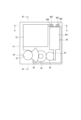
- FIG. 4 is a schematic plan view showing a state in which the cover of the electric actuator according to one embodiment is removed
- FIG. 5 is a cross-sectional view taken along line VV in FIG.
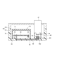
- FIG. 6 is a sectional view taken along line VI-VI of FIG.
- FIGS. 1-6 An electric actuator according to the present disclosure will be described below with reference to the drawings.
- FIGS. 1-6 An electric actuator according to the present disclosure will be described below with reference to the drawings.
- FIGS. 1-6 An electric actuator according to the present disclosure will be described below with reference to the drawings.
- FIGS. 1-6 An electric actuator according to the present disclosure will be described below with reference to the drawings.
- FIGS. 1-6 An electric actuator according to the present disclosure will be described below with reference to the drawings.
- FIGS. 1-6 An electric actuator according to the present disclosure will be described below with reference to the drawings.
- FIGS. 1-6 An electric actuator according to the present disclosure will be described below with reference to the drawings.
- FIGS. 1-6 An electric actuator according to the present disclosure will be described below with reference to the drawings.
- FIGS. 1-6 An electric actuator according to the present disclosure will be described below with reference to the drawings.
- FIGS. 1-6 An electric actuator according
- the electric actuator 10 is of a rotary type and is composed of, for example, a brushed DC motor and a reduction gear mechanism.
- the electric actuator 10 functions as a drive source for the detent mechanism 20 by rotating the output shaft 15 . Details of the electric actuator 10 will be described later.
- the detent mechanism 20 has a detent plate 21 , a detent spring 25 and the like, and transmits rotational driving force output from the electric actuator 10 to the parking lock mechanism 30 .
- the detent plate 21 is fixed to the output shaft 15 and driven by the electric actuator 10 .
- the detent spring 25 is an elastically deformable plate-like member, and a detent roller 26 is provided at its tip.
- the detent spring 25 urges the detent roller 26 toward the rotation center of the detent plate 21 .
- the detent spring 25 When a rotational force greater than or equal to a predetermined amount is applied to the detent plate 21 , the detent spring 25 is elastically deformed, and the detent roller 26 moves between the troughs 211 and 212 . By fitting the detent roller 26 into one of the troughs 211 and 212, the swinging of the detent plate 21 is restricted, and the state of the parking lock mechanism 30 is fixed.
- the parking lock mechanism 30 has a parking rod 31 , a cone 32 , a parking lever 33 , a shaft portion 34 and a parking gear 35 .
- the parking rod 31 is formed in a substantially L shape, and one end 311 side is fixed to the detent plate 21 .
- a cone 32 is provided on the other end 312 side of the parking rod 31 .
- the conical body 32 is formed so as to decrease in diameter toward the other end 312 side.
- the parking lever 33 abuts on the conical surface of the conical body 32 and is provided so as to be able to swing about the shaft portion 34 .
- a convex portion 331 that can mesh with the parking gear 35 is provided on the parking gear 35 side of the parking lever 33 .
- the parking gear 35 is connected to a drive shaft (not shown) and provided so as to be able to mesh with the projection 331 of the parking lever 33 .
- the rotation of the drive shaft is restricted.
- the shift range is the not P range, which is a range other than P
- the parking gear 35 is not locked by the parking lever 33 and the rotation of the drive shaft is not hindered by the parking lock mechanism 30 .
- the shift range is in the P range
- the parking gear 35 is locked by the parking lever 33 and the rotation of the drive shaft is restricted.
- the electric actuator 10 has a motor 40, a speed reduction mechanism 42, a housing 50, a board 60, a board cover 70, and the like.
- the motor 40 is placed horizontally on the board cover 70 so that the motor shaft is substantially parallel to the bottom surface of the case 51 .
- the speed reduction mechanism 42 has a worm gear 43 , a helical gear 44 , an intermediate gear 45 , a driven plate 46 and a driven shaft 47 .
- the gears forming the reduction mechanism 42 are made of metal, but at least a part of them may be made of resin.
- the worm gear 43 rotates together with the motor shaft of the motor 40 .
- the helical gear 44 meshes with the large diameter portions of the worm gear 43 and the intermediate gear 45 .
- the intermediate gear 45 has a large diameter portion and a small diameter portion, the large diameter portion meshing with the helical gear 44 and the small diameter portion meshing with the driven plate 46 .
- Helical gear 44 and intermediate gear 45 are rotatably supported by cover 58 .
- the driven plate 46 and the driven shaft 47 are integrally formed. Driven shaft 47 is rotatably supported by cover 58 and connected to output shaft 15 . Thereby, the rotation of the motor 40 is transmitted to the output shaft 15 via the worm gear 43 , helical gear 44 , intermediate gear 45 , driven plate 46 and driven shaft 47 .
- the housing 50 has a case 51 and a cover 58.
- the case 51 and the cover 58 are fixed and sealed with bolts or the like.
- Motor 40 , speed reduction mechanism 42 , board 60 and board cover 70 are housed inside housing 50 .
- the case 51 is made of, for example, resin.
- the case 51 has a case bottom portion 52 and a case peripheral wall 53 erected along the outer edge of the case bottom portion 52, and is generally rectangular in plan view.
- a terminal 61 is molded on the case bottom portion 52 .
- the terminal 61 includes lead wires 66, 406, etc., which will be described later.
- a tubular portion 54 is formed in the case 51 at a location corresponding to the driven shaft 47 .
- the cylindrical portion 54 is formed in a cylindrical shape that opens toward the driven shaft 47 , and is provided so that the end surface thereof can abut against the driven shaft 47 . Due to the contact between the driven shaft 47 and the tubular portion 54 , the axial load of the driven shaft 47 is applied to the tubular portion 54 .
- the substrate 60 is fixed to a substrate fixing portion 56 erected on the case bottom portion 52 with a bolt or the like (not shown).
- the substrate 60 is mounted with electronic components such as a microcomputer related to drive control of the motor 40 and switching elements constituting a driver circuit.
- the substrate 60 is connected with terminals 61 .
- the substrate cover 70 has a bottom portion 71 and a cover peripheral wall 75, which are integrally formed of, for example, resin.
- the substrate cover 70 is arranged inside the case peripheral wall 53 and accommodates the substrate 60 therein.
- the open end of the substrate cover 70 is inserted into the cover insertion groove 55 formed in the case bottom portion 52 .
- a motor 40 is placed on the board cover 70 .
- the motor 40 is held in the housing 50 so that the substrate cover 70 and the cover 58 sandwich the motor case 401 from the radial side.
- the board cover 70 supports one end side of the rotation shaft of the helical gear 44 and the intermediate gear 45 and is configured to receive the axial load of the helical gear 44 and the intermediate gear 45 .
- a step is provided at the location where the motor 40 and the deceleration mechanism 42 are provided so that the substrate cover 70 is lowered. As a result, the size in the height direction can be reduced.
- the motor terminal 405 is formed so as to protrude from one end of the motor case 401 .
- the lead wire 406 has one end connected to the motor terminal 405 and the other end connected to the substrate 60 .
- An intermediate portion 407 of lead wire 406 is molded into case 51 .
- the lead wires 406 are configured to straddle the board cover 70 inside the case 51 and electrically connect the motor terminals 405 and the board 60 . Note that the cover 58 is omitted in FIG. 4 for the sake of explanation.
- a sensor magnet 48 is provided at the end of the driven shaft 47 facing the case 51 .
- a rotational position sensor 65 is provided at a portion of the case 51 facing the sensor magnet 48 . That is, in this embodiment, the rotational position sensor 65 is separated from the substrate 60 and mounted on the case 51 .
- the rotational position sensor 65 has a body portion 651 and a sensor terminal 652 , the body portion 651 is exposed to the driven shaft 47 side, and the sensor terminal 652 is molded on the case 51 .
- the lead wire 66 has one end connected to the sensor terminal 652 of the rotational position sensor 65 and the other end connected to the substrate 60 .
- the sensor terminal 652 and the lead wire 66 are connected while being embedded in the case 51 .
- the connecting portion between the sensor terminal 652 and the lead wire 66 is molded in the case 51 .
- a middle portion 667 of the lead wire 66 is molded to the case 51 .
- the lead wire 66 is configured to straddle the board cover 70 inside the case 51 and electrically connect the rotational position sensor 65 and the board 60 .
- a substrate cover 70 is provided, and the substrate 60 is separated from the motor 40 and the reduction mechanism 42 by the substrate cover 70 .
- foreign matter such as abrasion powder generated by the motor 40 and the speed reduction mechanism 42 can be prevented from entering the substrate 60 side.
- the electric actuator 10 includes the motor 40, the speed reduction mechanism 42, the substrate 60, the housing 50, the substrate cover 70, the rotational position sensor 65, and the lead wires 406,66.
- the deceleration mechanism 42 decelerates the rotation of the motor and transmits it to the output shaft 15 .
- the substrate 60 is mounted with electronic components related to drive control of the motor 40 .
- the housing 50 has a case 51 and a cover 58 and accommodates the motor 40, the speed reduction mechanism 42 and the board 60 inside.
- the board cover 70 engages with the case 51 inside the housing 50 to separate the motor 40 and speed reduction mechanism 42 from the board 60 .
- the rotational position sensor 65 is provided inside the housing 50 and outside the substrate cover 70 to detect the rotational position of the speed reduction mechanism 42 .
- the object to be detected is the driven shaft 47
- the rotational position sensor 65 detects the rotational position of the driven shaft 47 .
- Lead wires 406 connect motor 40 and substrate 60 inside housing 50 .
- a lead wire 66 connects the rotational position sensor 65 and the substrate 60 inside the housing 50 .
- a substrate cover 70 covering the substrate 60 is provided, and a rotation position sensor 65 that needs to be provided facing the object to be detected is arranged outside the substrate cover 70 . It is possible to prevent foreign matter such as abrasion powder from reaching the substrate 60 and causing an abnormality such as a short circuit.
- the lead wire 406 has one end connected to the motor 40 outside the board cover 70 , the other end connected to the board 60 inside the board cover 70 , and an intermediate portion 407 molded to the case 51 .
- the motor 40 and the substrate 60 can be electrically connected without opening through-holes for inserting terminals or the like in the substrate cover 70, and foreign matter can be prevented from entering the substrate cover 70. can.
- the lead wire 66 has one end connected to the rotational position sensor 65 outside the board cover 70 , the other end connected to the board 60 inside the board cover 70 , and an intermediate portion 667 molded to the case 51 .
- the rotation position sensor 65 and the substrate 60 can be electrically connected without opening a through-hole for inserting a terminal or the like in the substrate cover 70, and foreign matter is prevented from entering the substrate cover 70. be able to.
- the rotational position sensor 65 has a body portion 651 and a sensor terminal 652.
- the body portion 651 is exposed from the case 51 on the side facing the sensor magnet 48 provided in the deceleration mechanism 42, and the sensor terminal 652 is molded on the case 51. It is As a result, it is possible to prevent foreign matter such as abrasion powder generated from the motor 40 and the speed reduction mechanism 42 from adhering to the sensor terminal 652 .
- the case 51 is provided outside the rotational position sensor 65 and integrally formed with a cylindrical portion 54 capable of coming into contact with the driven shaft 47 to be detected by the rotational position sensor 65 .
- the number of parts can be reduced as compared with the case where the member that receives the axial load of the driven shaft 47 is configured as a separate member.
- the motor 40 drives the parking lock mechanism 30.
- the configuration of the electric actuator 10 for driving the parking lock mechanism 30 can be simplified.
- the driven shaft 47 is the “shaft”
- the sensor magnet 48 is the “detected part”
- the lead wire 406 is the “motor connection wire”
- the intermediate part 407 is the “motor connection wire intermediate part”
- the lead wire 66 is the “sensor connection line”
- the intermediate portion 667 corresponds to the “sensor connection line intermediate portion”.
- the magnet which is the part to be detected, is provided on the driven shaft, and the rotational position sensor detects the rotational position of the driven shaft as a detection target.
- gears other than the driven shaft that constitutes the speed reduction mechanism may be the detection target, and the detected part and the rotational position sensor may be provided at locations corresponding to the detection targets.
- the sensor magnet is provided on the driven shaft.
- the rotational position sensor side may have a magnetic material, and the shaft side may have a conductor (a material that responds to magnetism). In this case, the conductor provided on the shaft side corresponds to the "detected portion".
- the reduction mechanism is composed of worm gears, helical gears, intermediate gears, and the like.
- the configuration of the speed reduction mechanism and the number of speed reduction stages may differ from those of the above embodiments.
- the helical gear and intermediate gear are rotatably supported by the cover.
- the gear that constitutes the reduction gear may be configured to be rotatably supported by the case or board cover.
- the driven plate and the driven shaft are integrally formed in the above embodiment, they may be separate bodies in other embodiments.
- the board is fixed to the case with bolts or the like.
- fixing members and fixing methods other than bolts may be used to fix the substrate to the case, such as heat caulking.
- the motor is a brushed DC motor. In other embodiments, the motor may be other than a brushed DC motor.
- the detent plate is provided with two valleys. In other embodiments, the number of valleys is not limited to two, and may be three or more. Also, the detent mechanism, the parking lock mechanism, and the like may be different from those in the above embodiment.
- the electric actuator is applied to the parking lock system.
- the electric actuator may be applied to in-vehicle systems other than parking lock systems or drive systems other than in-vehicle systems.
- the present disclosure is by no means limited to the above embodiments, and can be implemented in various forms without departing from the scope of the present disclosure.
Landscapes
- Engineering & Computer Science (AREA)
- General Engineering & Computer Science (AREA)
- Mechanical Engineering (AREA)
- Connection Of Motors, Electrical Generators, Mechanical Devices, And The Like (AREA)
- Gear-Shifting Mechanisms (AREA)
Abstract
電動アクチュエータ(10)は、モータ(40)と、減速機構(42)と、基板(60)と、ハウジング(50)と、基板カバー(70)と、回転位置センサ(65)と、モータ接続線(406)と、センサ接続線(66)と、を備える。ハウジング(50)は、ケース(51)およびカバー(58)を有し、モータ(40)、減速機構(42)および基板(60)を内部に収容する。基板カバー(70)は、ハウジング(50)の内部にてケース(51)と係合し、モータ(40)および減速機構(42)と基板(60)とを離隔する。回転位置センサ(65)は、ハウジング(50)の内部かつ基板カバー(70)の外部に設けられる。モータ接続線(406)は、ハウジング(50)の内部にて、モータ(40)と基板(60)とを接続する。センサ接続線(66)は、ハウジング(50)の内部にて、回転位置センサ(65)と基板(60)とを接続する。
Description
本出願は、2022年2月18日に出願された特許出願番号2022-023754号に基づくものであり、ここにその記載内容を援用する。
本開示は、電動アクチュエータに関する。
従来、モータの駆動力が伝達されるギアの回転を検出可能な構成が知られている。例えば特許文献1では、ウォームスクリューにより駆動されるタービンに永久磁石が設けられており、基板に実装されたリニアホール素子にてタービンの回転を検出している。
しかしながら、特許文献1のように、モータおよびギアと基板との間を隔離する部材がなく、ブラシ付きDCモータや金属ギアなどの場合、導電性部材の摩耗粉等が基板側へ到達し、電子部品のショート等の異常が発生する虞がある。本開示の目的は、基板側への異物の侵入を抑制可能な電動アクチュエータを提供することにある。
本開示の電動アクチュエータは、モータと、減速機構と、基板と、ハウジングと、基板カバーと、回転位置センサと、モータ接続線と、を備える。
減速機構は、モータの回転を減速して出力軸に伝達する。基板は、モータの駆動制御に係る電子部品が実装される。ハウジングは、ケースおよびカバーを有し、モータ、減速機構および基板を内部に収容する。基板カバーは、ハウジングの内部にてケースと係合し、モータおよび減速機構と基板とを離隔する。回転位置センサは、ハウジングの内部かつ基板カバーの外部に設けられ、減速機構の回転位置を検出する。モータ接続線は、ハウジング内部にて、モータと基板とを接続する。センサ接続線は、ハウジングの内部にて、回転位置センサと基板とを接続する。これにより、基板側への異物の侵入を抑制可能である。
本開示についての上記目的及びその他の目的、特徴や利点は、添付の図面を参照しながら下記の詳細な記述により、より明確になる。その図面は、
図1は、一実施形態によるパークロックシステムを示す概略構成図であり、
図2は、一実施形態による電動アクチュエータのカバーを外した状態を示す斜視図であり、
図3は、一実施形態によるケースに基板を組み付けた状態を示す斜視図であり、
図4は、一実施形態による電動アクチュエータのカバーを外した状態を示す模式的な平面図であり、
図5は、図4のV-V線断面図であり、
図6は、図4のVI-VI線断面図である。
(一実施形態)
以下、本開示による電動アクチュエータを図面に基づいて説明する。一実施形態を図1~図6に示す。図1に示すように、電動アクチュエータ10は、パークロックシステム1に適用される。パークロックシステム1は、電動アクチュエータ10、ディテント機構20、および、パーキングロック機構30を備える。
以下、本開示による電動アクチュエータを図面に基づいて説明する。一実施形態を図1~図6に示す。図1に示すように、電動アクチュエータ10は、パークロックシステム1に適用される。パークロックシステム1は、電動アクチュエータ10、ディテント機構20、および、パーキングロック機構30を備える。
電動アクチュエータ10は、回転式であって、例えばブラシ付きDCモータおよび減速ギア機構等から構成される。電動アクチュエータ10は、出力軸15を回転させることで、ディテント機構20の駆動源として機能する。電動アクチュエータ10の詳細は後述する。
ディテント機構20は、ディテントプレート21、および、ディテントスプリング25等を有し、電動アクチュエータ10から出力された回転駆動力を、パーキングロック機構30へ伝達する。
ディテントプレート21は、出力軸15に固定され、電動アクチュエータ10により駆動される。ディテントプレート21のディテントスプリング25側には、2つの谷部211、212、および、谷部211、212を隔てる山部215が設けられる。
ディテントスプリング25は、弾性変形可能な板状部材であり、先端にディテントローラ26が設けられる。ディテントスプリング25は、ディテントローラ26をディテントプレート21の回動中心側に付勢する。
ディテントプレート21に所定以上の回転力が加わると、ディテントスプリング25が弾性変形し、ディテントローラ26が谷部211、212間を移動する。ディテントローラ26が谷部211、212のいずれかに嵌まり込むことで、ディテントプレート21の揺動が規制され、パーキングロック機構30の状態が固定される。
パーキングロック機構30は、パーキングロッド31、円錐体32、パーキングレバー33、軸部34、および、パーキングギア35を有する。パーキングロッド31は、略L字形状に形成され、一端311側がディテントプレート21に固定される。パーキングロッド31の他端312側には、円錐体32が設けられる。円錐体32は、他端312側にいくほど縮径するように形成される。ディテントローラ26がPレンジに対応する谷部211に嵌まり込む方向にディテントプレート21が回転すると、円錐体32が矢印Pの方向に移動する。
パーキングレバー33は、円錐体32の円錐面と当接し、軸部34を中心に揺動可能に設けられる。パーキングレバー33のパーキングギア35側には、パーキングギア35と噛み合い可能な凸部331が設けられる。ディテントプレート21の回転により、円錐体32が矢印P方向に移動すると、パーキングレバー33が押し上げられ、凸部331とパーキングギア35とが噛み合う。一方、円錐体32が矢印notP方向に移動すると、凸部331とパーキングギア35との噛み合いが解除される。
パーキングギア35は、図示しないドライブシャフトと接続しており、パーキングレバー33の凸部331と噛み合い可能に設けられる。パーキングギア35と凸部331とが噛み合うと、ドライブシャフトの回転が規制される。シフトレンジがP以外のレンジであるnotPレンジのとき、パーキングギア35はパーキングレバー33によりロックされず、ドライブシャフトの回転は、パーキングロック機構30により妨げられない。また、シフトレンジがPレンジのとき、パーキングギア35はパーキングレバー33によってロックされ、ドライブシャフトの回転が規制される。
図2および図3に示すように、電動アクチュエータ10は、モータ40、減速機構42、ハウジング50、基板60、および、基板カバー70等を有する。モータ40は、モータ軸がケース51の底面と略平行になるように基板カバー70上に横置きされている。
減速機構42は、ウォームギア43、ヘリカルギア44、中間ギア45、ドリブンプレート46およびドリブンシャフト47を有する。本実施形態では、減速機構42を構成するギアは金属で形成されているが、少なくとも一部を樹脂で形成してもよい。
ウォームギア43は、モータ40のモータ軸と一体に回転する。ヘリカルギア44は、ウォームギア43および中間ギア45の大径部と噛み合う。中間ギア45は大径部および小径部を有し、大径部はヘリカルギア44と噛み合い、小径部はドリブンプレート46と噛み合う。ヘリカルギア44および中間ギア45は、カバー58にて回転可能に支持されている。
ドリブンプレート46とドリブンシャフト47とは、一体に形成される。ドリブンシャフト47は、カバー58に回転可能に支持され、出力軸15と接続される。これにより、モータ40の回転は、ウォームギア43、ヘリカルギア44、中間ギア45、ドリブンプレート46およびドリブンシャフト47を経由し、出力軸15に伝達される。
図3~図6に示すように、ハウジング50は、ケース51、および、カバー58を有する。ケース51とカバー58とは、ボルト等にて固定され、封止される。モータ40、減速機構42、基板60および基板カバー70は、ハウジング50の内部に収容される。
ケース51は、例えば樹脂等で形成される。ケース51は、ケース底部52およびケース底部52の外縁に沿って立設されるケース周壁53を有し、平面視略矩形に形成される。ケース底部52には、端子61がモールドされている。端子61には、後述するリード線66、406等が含まれる。
ケース51には、ドリブンシャフト47と対応する箇所に筒部54が形成されている。筒部54は、ドリブンシャフト47側に開口する筒状に形成されており、端面にてドリブンシャフト47と当接可能に設けられている。ドリブンシャフト47と筒部54とが当接することで、筒部54はドリブンシャフト47の軸方向の荷重を受ける。
基板60は、図示しないボルト等にてケース底部52に立設される基板固定部56に固定される。基板60には、モータ40の駆動制御に係るマイコンやドライバ回路を構成するスイッチング素子等の電子部品が実装されている。基板60は、端子61と接続される。
基板カバー70は、底部71およびカバー周壁75を有し、例えば樹脂等で一体に形成されている。基板カバー70は、ケース周壁53の内側に配置され、内部に基板60を収容する。基板カバー70の開口側の先端は、ケース底部52に形成されるカバー挿入溝55に挿入される。
基板カバー70には、モータ40が載せ置かれる。モータ40は、基板カバー70とカバー58とでモータケース401を径方向側から挟み込むようにしてハウジング50内に保持されている。また、基板カバー70は、ヘリカルギア44および中間ギア45の回転軸の一端側を支持し、ヘリカルギア44および中間ギア45の軸方向の荷重を受けるように構成されている。本実施形態では、モータ40および減速機構42が設けられる箇所は、基板カバー70が低くなるように段差が設けられている。これにより、高さ方向の体格を小型化可能である。
図4および図5に示すように、モータ端子405は、モータケース401の一端から突出して形成されている。リード線406は、一端がモータ端子405と接続され、他端が基板60と接続されている。リード線406の中間部407は、ケース51にモールドされている。リード線406は、ケース51の内部にて基板カバー70を跨ぐように構成されており、モータ端子405と基板60とを電気的に接続する。なお図4では、説明のためカバー58を省略した。
図6に示すように、ドリブンシャフト47のケース51と対向する側の端部には、センサマグネット48が設けられている。ケース51のセンサマグネット48と対向する箇所には、回転位置センサ65が設けられている。すなわち本実施形態では、回転位置センサ65は、基板60から分離してケース51に搭載されている。回転位置センサ65は、本体部651およびセンサ端子652を有し、本体部651がドリブンシャフト47側に露出し、センサ端子652がケース51にモールドされている。
リード線66は、一端が回転位置センサ65のセンサ端子652と接続され、他端が基板60と接続されている。センサ端子652とリード線66とは、ケース51に埋め込まれた状態にて接続されている。換言すると、センサ端子652とリード線66との接続部はケース51にモールドされている。リード線66の中間部667はケース51にモールドされている。リード線66は、ケース51の内部にて基板カバー70を跨ぐように構成されており、回転位置センサ65と基板60とを電気的に接続する。
本実施形態では、基板カバー70が設けられており、基板カバー70により、基板60と、モータ40および減速機構42とが離隔されている。これにより、モータ40および減速機構42により発生する摩耗粉等の異物が基板60側へ侵入するのを防ぐことができる。
また、リード線406、66は、中間部407、667がケース51にモールドされており、一端側が基板カバー70の外側にてモータ端子405、回転位置センサ65と接続され、他端側が基板カバー70の内側にて露出して基板60と接続されている。これにより、リード線406、66を外部に取り出すための貫通孔を基板カバー70に設ける必要がなく、貫通孔からの異物侵入を防ぐことができる。
以上説明したように、電動アクチュエータ10は、モータ40と、減速機構42と、基板60と、ハウジング50と、基板カバー70と、回転位置センサ65と、リード線406、66と、を備える。減速機構42は、モータの回転を減速して出力軸15に伝達する。基板60は、モータ40の駆動制御に係る電子部品が実装される。ハウジング50は、ケース51およびカバー58を有し、モータ40、減速機構42および基板60を内部に収容する。
基板カバー70は、ハウジング50の内部にてケース51と係合し、モータ40および減速機構42と基板60とを離隔する。回転位置センサ65は、ハウジング50の内部かつ基板カバー70の外部に設けられ、減速機構42の回転位置を検出する。本実施形態では、検出対象はドリブンシャフト47であって、回転位置センサ65はドリブンシャフト47の回転位置を検出する。リード線406は、ハウジング50の内部にて、モータ40と基板60とを接続する。リード線66は、ハウジング50の内部にて、回転位置センサ65と基板60とを接続する。
本実施形態では、基板60を覆う基板カバー70を設け、検出対象と対向させて設ける必要のある回転位置センサ65を基板カバー70の外側に配置することで、モータ40および減速機構42から発生する摩耗粉等の異物が基板60に到達し、ショート故障等の異常が発生するのを防ぐことができる。
リード線406は、一端が基板カバー70の外側にてモータ40と接続され、他端が基板カバー70の内側にて基板60と接続され、中間部407がケース51にモールドされている。これにより、基板カバー70に端子等を挿通するための貫通孔を開けることなく、モータ40と基板60とを電気的に接続することができ、基板カバー70内部への異物の侵入を防ぐことができる。
リード線66は、一端が基板カバー70の外側にて回転位置センサ65と接続され、他端が基板カバー70の内側にて基板60と接続され、中間部667がケース51にモールドされている。これにより、基板カバー70に端子等を挿通するための貫通孔を開けることなく、回転位置センサ65と基板60とを電気的に接続することができ、基板カバー70内部への異物の侵入を防ぐことができる。
回転位置センサ65は、本体部651およびセンサ端子652を有し、減速機構42に設けられるセンサマグネット48と対向する側にて本体部651がケース51から露出し、センサ端子652がケース51にモールドされている。これにより、モータ40および減速機構42から発生する摩耗粉等の異物がセンサ端子652に付着するのを防ぐことができる。
ケース51は、回転位置センサ65の外側に設けられ、回転位置センサ65の検出対象であるドリブンシャフト47と当接可能な筒部54が一体に形成されている。これにより、ドリブンシャフト47の軸方向荷重を受ける部材を別部材で構成する場合と比較し、部品点数を低減することができる。
モータ40は、パーキングロック機構30を駆動する。これにより、パーキングロック機構30の駆動に係る電動アクチュエータ10の構成を簡素化することができる。
実施形態では、ドリブンシャフト47が「シャフト」、センサマグネット48が「被検出部」、リード線406が「モータ接続線」、中間部407が「モータ接続線中間部」、リード線66が「センサ接続線」、中間部667が「センサ接続線中間部」に対応する。
(他の実施形態)
上記実施形態では、被検出部であるマグネットはドリブンシャフトに設けられ、回転位置センサは検出対象としてドリブンシャフトの回転位置を検出する。他の実施形態では、減速機構を構成するドリブンシャフト以外のギアを検出対象としてもよく、被検出部および回転位置センサは検出対象に応じた箇所に設ければよい。また上記実施形態では、ドリブンシャフトにセンサマグネットが設けられている。他の実施形態では、回転位置センサ側に磁性体を持ち、シャフト側に導体(磁気に反応する材料)を設けるようにしてもよい。この場合、シャフト側に設けられる導体が「被検出部」に対応する。
上記実施形態では、被検出部であるマグネットはドリブンシャフトに設けられ、回転位置センサは検出対象としてドリブンシャフトの回転位置を検出する。他の実施形態では、減速機構を構成するドリブンシャフト以外のギアを検出対象としてもよく、被検出部および回転位置センサは検出対象に応じた箇所に設ければよい。また上記実施形態では、ドリブンシャフトにセンサマグネットが設けられている。他の実施形態では、回転位置センサ側に磁性体を持ち、シャフト側に導体(磁気に反応する材料)を設けるようにしてもよい。この場合、シャフト側に設けられる導体が「被検出部」に対応する。
上記実施形態では、減速機構は、ウォームギア、ヘリカルギアおよび中間ギア等によって構成されている。他の実施形態では、減速機構の構成や減速段数は、上記実施形態と異なっていてもよい。例えば、上記実施形態では、ヘリカルギアおよび中間ギアは、カバーに回転可能に支持されている。他の実施形態では、減速ギアを構成するギアは、ケースや基板カバーに回転可能に支持されるように構成してもよい。また、上記実施形態では、ドリブンプレートとドリブンシャフトとが一体に形成されているが、他の実施形態では別体としてもよい。上記実施形態では、基板はボルト等にてケースに固定されている。他の実施形態では、基板のケースへの固定にはボルト以外の固定部材や固定方法を用いてもよく、例えば熱かしめ等であってもよい。
上記実施形態では、モータは、ブラシ付きDCモータである。他の実施形態では、モータは、ブラシ付きDCモータ以外のものであってもよい。上記実施形態では、ディテントプレートには2つの谷部が設けられる。他の実施形態では、谷部の数は2つに限らず、3以上であってもよい。また、ディテント機構やパーキングロック機構等は、上記実施形態と異なっていてもよい。
上記実施形態では、電動アクチュエータはパークロックシステムに適用される。他の実施形態では、電動アクチュエータをパークロックシステム以外の車載システム、または、車載以外の駆動システムに適用してもよい。以上、本開示は、上記実施形態になんら限定されるものではなく、その趣旨を逸脱しない範囲において種々の形態で実施可能である。
本開示は実施形態に準拠して記述された。しかしながら、本開示は当該実施形態および構造に限定されるものではない。本開示は、様々な変形例および均等の範囲内の変形をも包含する。また、様々な組み合わせおよび形態、さらには、それらに一要素のみ、それ以上、あるいはそれ以下、を含む他の組み合わせおよび形態も、本開示の範疇および思想範囲に入るものである。
Claims (6)
- モータ(40)と、
前記モータの回転を減速して出力軸(15)に伝達する減速機構(42)と、
前記モータの駆動制御に係る電子部品が実装される基板(60)と、
ケース(51)およびカバー(58)を有し、前記モータ、前記減速機構および前記基板を内部に収容するハウジング(50)と、
前記ハウジングの内部にて前記ケースと係合し、前記モータおよび前記減速機構と前記基板とを離隔する基板カバー(70)と、
前記ハウジングの内部かつ前記基板カバーの外部に設けられ、前記減速機構の回転位置を検出する回転位置センサ(65)と、
前記ハウジングの内部にて、前記モータと前記基板とを接続するモータ接続線(406)と、
前記ハウジングの内部にて、前記回転位置センサと前記基板とを接続するセンサ接続線(66)と、
を備える電動アクチュエータ。 - 前記モータ接続線は、一端が前記基板カバーの外側にて前記モータと接続され、他端が前記基板カバーの内側にて前記基板と接続され、モータ接続線中間部(407)が前記ケースにモールドされている請求項1に記載の電動アクチュエータ。
- 前記センサ接続線は、一端が前記基板カバーの外側にて前記回転位置センサと接続され、他端が前記基板カバーの内側にて前記基板と接続され、センサ接続線中間部(667)が前記ケースにモールドされている請求項1または2に記載の電動アクチュエータ。
- 前記回転位置センサは、本体部(651)およびセンサ端子(652)を有し、前記減速機構に設けられる被検出部(48)と対向する側にて前記本体部が前記ケースから露出し、前記センサ端子が前記ケースにモールドされている請求項1~3のいずれか一項に記載の電動アクチュエータ。
- 前記ケースは、前記回転位置センサの外側に設けられ、前記回転位置センサの検出対象であるシャフト(47)と当接可能な筒部(54)が一体に形成されている請求項1~4のいずれか一項に記載の電動アクチュエータ。
- 前記モータは、パーキングロック機構(30)を駆動する請求項1~5のいずれか一項に記載の電動アクチュエータ。
Applications Claiming Priority (2)
| Application Number | Priority Date | Filing Date | Title |
|---|---|---|---|
| JP2022023754A JP2023120739A (ja) | 2022-02-18 | 2022-02-18 | 電動アクチュエータ |
| JP2022-023754 | 2022-02-18 |
Publications (1)
| Publication Number | Publication Date |
|---|---|
| WO2023157751A1 true WO2023157751A1 (ja) | 2023-08-24 |
Family
ID=87578139
Family Applications (1)
| Application Number | Title | Priority Date | Filing Date |
|---|---|---|---|
| PCT/JP2023/004345 Ceased WO2023157751A1 (ja) | 2022-02-18 | 2023-02-09 | 電動アクチュエータ |
Country Status (2)
| Country | Link |
|---|---|
| JP (1) | JP2023120739A (ja) |
| WO (1) | WO2023157751A1 (ja) |
Citations (2)
| Publication number | Priority date | Publication date | Assignee | Title |
|---|---|---|---|---|
| JP2012061949A (ja) * | 2010-09-16 | 2012-03-29 | Hitachi Automotive Systems Ltd | モータユニット |
| JP2014159234A (ja) * | 2013-02-20 | 2014-09-04 | Nsk Ltd | 電動パワーステアリング装置 |
-
2022
- 2022-02-18 JP JP2022023754A patent/JP2023120739A/ja active Pending
-
2023
- 2023-02-09 WO PCT/JP2023/004345 patent/WO2023157751A1/ja not_active Ceased
Patent Citations (2)
| Publication number | Priority date | Publication date | Assignee | Title |
|---|---|---|---|---|
| JP2012061949A (ja) * | 2010-09-16 | 2012-03-29 | Hitachi Automotive Systems Ltd | モータユニット |
| JP2014159234A (ja) * | 2013-02-20 | 2014-09-04 | Nsk Ltd | 電動パワーステアリング装置 |
Also Published As
| Publication number | Publication date |
|---|---|
| JP2023120739A (ja) | 2023-08-30 |
Similar Documents
| Publication | Publication Date | Title |
|---|---|---|
| US20180062479A1 (en) | Modular Vehicle Engine Component Actuator | |
| JP3848275B2 (ja) | 内燃機関の絞り弁制御装置 | |
| CN101678781B (zh) | 车辆用位置检测装置以及座椅位置检测装置 | |
| CA2811939C (en) | Linear actuator | |
| US20120137800A1 (en) | Parking release actuator | |
| US8193668B2 (en) | Motor with speed reduction mechanism capable of absorbing axial deviation between armature shaft and worm shaft | |
| EP3480925A1 (en) | Wiper motor | |
| US20040061391A1 (en) | Motor having connector housing | |
| CN108316802B (zh) | 一种可手动操作的旋转门电动启闭促动器及其工作方法 | |
| JP5559864B2 (ja) | 電動補助駆動装置、特にワイパ駆動装置 | |
| US6204582B1 (en) | Servo motor assembly and method of making same | |
| CN112703337B (zh) | 旋转式致动器 | |
| CN210273735U (zh) | 电动致动器 | |
| KR102811960B1 (ko) | 구동 트레인의 작동을 위한 구동부의 설계 개념 | |
| US12467520B2 (en) | Electric actuator | |
| WO2023157751A1 (ja) | 電動アクチュエータ | |
| US11079012B2 (en) | Rotary actuator | |
| KR102367482B1 (ko) | 차량용 전자식 변속기 제어용 액츄에이터 | |
| WO2018181119A1 (ja) | 電動アクチュエータおよび電動アクチュエータの製造方法 | |
| JP6081810B2 (ja) | モータアクチュエータ | |
| US20210083550A1 (en) | Electric actuator | |
| JP2010057296A (ja) | 電動モータ及びサンルーフモータ | |
| US20260016062A1 (en) | Electric braking device | |
| JP4137296B2 (ja) | モータ | |
| KR102673276B1 (ko) | Sbw 액추에이터 |
Legal Events
| Date | Code | Title | Description |
|---|---|---|---|
| 121 | Ep: the epo has been informed by wipo that ep was designated in this application |
Ref document number: 23756277 Country of ref document: EP Kind code of ref document: A1 |
|
| NENP | Non-entry into the national phase |
Ref country code: DE |
|
| 122 | Ep: pct application non-entry in european phase |
Ref document number: 23756277 Country of ref document: EP Kind code of ref document: A1 |