WO2023157133A1 - Wireless communication method, wireless communication system, and transmission device - Google Patents
Wireless communication method, wireless communication system, and transmission device Download PDFInfo
- Publication number
- WO2023157133A1 WO2023157133A1 PCT/JP2022/006202 JP2022006202W WO2023157133A1 WO 2023157133 A1 WO2023157133 A1 WO 2023157133A1 JP 2022006202 W JP2022006202 W JP 2022006202W WO 2023157133 A1 WO2023157133 A1 WO 2023157133A1
- Authority
- WO
- WIPO (PCT)
- Prior art keywords
- phase shift
- shift amount
- transmission data
- wireless communication
- stream
- Prior art date
Links
- 230000005540 biological transmission Effects 0.000 title claims abstract description 136
- 238000000034 method Methods 0.000 title claims abstract description 53
- 238000004891 communication Methods 0.000 title claims abstract description 40
- 230000010363 phase shift Effects 0.000 claims abstract description 179
- 238000012545 processing Methods 0.000 claims description 50
- 238000010586 diagram Methods 0.000 description 26
- 230000003321 amplification Effects 0.000 description 11
- 238000003199 nucleic acid amplification method Methods 0.000 description 11
- 230000006870 function Effects 0.000 description 7
- 238000004364 calculation method Methods 0.000 description 6
- 238000004590 computer program Methods 0.000 description 2
- 230000000694 effects Effects 0.000 description 2
- 238000005562 fading Methods 0.000 description 2
- 238000000926 separation method Methods 0.000 description 2
- 238000013459 approach Methods 0.000 description 1
- 238000006243 chemical reaction Methods 0.000 description 1
- 238000005516 engineering process Methods 0.000 description 1
- 238000012986 modification Methods 0.000 description 1
- 230000004048 modification Effects 0.000 description 1
- 239000007787 solid Substances 0.000 description 1
Images


Classifications
-
- H—ELECTRICITY
- H04—ELECTRIC COMMUNICATION TECHNIQUE
- H04B—TRANSMISSION
- H04B7/00—Radio transmission systems, i.e. using radiation field
- H04B7/02—Diversity systems; Multi-antenna system, i.e. transmission or reception using multiple antennas
- H04B7/04—Diversity systems; Multi-antenna system, i.e. transmission or reception using multiple antennas using two or more spaced independent antennas
- H04B7/0413—MIMO systems
- H04B7/0456—Selection of precoding matrices or codebooks, e.g. using matrices antenna weighting
-
- Y—GENERAL TAGGING OF NEW TECHNOLOGICAL DEVELOPMENTS; GENERAL TAGGING OF CROSS-SECTIONAL TECHNOLOGIES SPANNING OVER SEVERAL SECTIONS OF THE IPC; TECHNICAL SUBJECTS COVERED BY FORMER USPC CROSS-REFERENCE ART COLLECTIONS [XRACs] AND DIGESTS
- Y02—TECHNOLOGIES OR APPLICATIONS FOR MITIGATION OR ADAPTATION AGAINST CLIMATE CHANGE
- Y02D—CLIMATE CHANGE MITIGATION TECHNOLOGIES IN INFORMATION AND COMMUNICATION TECHNOLOGIES [ICT], I.E. INFORMATION AND COMMUNICATION TECHNOLOGIES AIMING AT THE REDUCTION OF THEIR OWN ENERGY USE
- Y02D30/00—Reducing energy consumption in communication networks
- Y02D30/70—Reducing energy consumption in communication networks in wireless communication networks
Definitions
- the present invention relates to wireless communication technology.
- the present invention relates to a radio communication technique in which transmission data is precoded on the transmitting side.
- the transmitting side may precode the transmitted data. For example, when performing wideband transmission under a frequency selective fading environment, channel equalization is performed by precoding. As another example, multiple-input multiple-output (MIMO) systems perform stream separation by precoding.
- MIMO multiple-input multiple-output
- PAPR Peak to Average Power Ratio
- a transmission signal is amplified by a power amplifier before being transmitted from an antenna, and if a signal with a high PAPR is input to the power amplifier, it may be affected by the nonlinear characteristics of the power amplifier and cause nonlinear distortion. The occurrence of nonlinear distortion in the transmitted signal may result in erroneous communication.
- Non-Patent Document 1 discloses a technique for reducing PAPR in a wideband single-carrier MIMO system.
- the PAPR increases.
- One object of the present invention is to provide a technique capable of reducing PAPR when the transmission side precodes transmission data in wireless communication.
- a first aspect relates to a wireless communication method for performing wireless communication between a transmitting device and a receiving device.
- the wireless communication method is A phase shift amount determination process for determining a random phase shift amount for each stream of transmission data; A modulation process that modulates transmission data and further shifts the phase according to a random phase shift amount for each stream; precoding processing for precoding transmission data after modulation processing; and transmission processing for transmitting transmission data after precoding processing from a transmission device to a reception device.
- a second aspect relates to wireless communication systems.
- a wireless communication system includes a transmitter and a receiver.
- the transmitting device A phase shift amount determination process for determining a random phase shift amount for each stream of transmission data; A modulation process that modulates transmission data and further shifts the phase according to a random phase shift amount for each stream; precoding processing for precoding transmission data after modulation processing; and a transmission process of transmitting the transmission data after the precoding process from the transmission device to the reception device.
- a third aspect relates to a transmitting device that wirelessly communicates with a receiving device.
- the transmitting device a phase shift amount determination unit that determines a random phase shift amount for each stream of transmission data; a modulation unit that modulates the transmission data and further shifts the phase according to the random phase shift amount for each stream; a precoding unit that precodes the transmission data after the modulation process; and a transmitting unit configured to transmit the transmission data after the precoding process to the receiving device.
- the present invention it is possible to reduce the PAPR when the transmission side performs precoding on transmission data in wireless communication.
- FIG. 1 is a conceptual diagram schematically showing the configuration of a radio communication system according to an embodiment
- FIG. FIG. 2 is a block diagram showing a basic configuration example of a transmission device that performs precoding
- FIG. 4 is a conceptual diagram for explaining amplification characteristics of an amplifier
- FIG. 4 is a conceptual diagram for explaining distortion of constellation
- FIG. 4 is a conceptual diagram for explaining the basics of phase shift according to the embodiment
- FIG. 4 is a conceptual diagram for explaining an overview of phase shift according to the embodiment
- FIG. 4 is a conceptual diagram for explaining an example of random phase shift according to the embodiment
- FIG. 4 is a conceptual diagram for explaining signal addition processing according to the embodiment
- FIG. 4 is a conceptual diagram for explaining the effect of phase shift according to the embodiment; 4 is a flow chart summarizing processing by a transmitting device according to an embodiment; 1 is a block diagram showing a first configuration example of a transmission device according to an embodiment; FIG. FIG. 10 is a block diagram showing a second configuration example of a transmission device according to an embodiment; FIG. 11 is a block diagram showing a third configuration example of a transmission device according to an embodiment; 1 is a block diagram showing a configuration example of a receiving device according to an embodiment; FIG.
- FIG. 1 is a conceptual diagram schematically showing the configuration of a radio communication system 1 according to this embodiment.
- a wireless communication system 1 includes a transmitter 100 and a receiver 200 .
- the transmitting device 100 and the receiving device 200 perform wireless communication.
- the radio communication system 1 may be a MIMO (Multiple-Input Multiple-Output) system, a SISO (Single-Input Single-Output) system, or others.
- the radio communication system 1 may perform single-carrier transmission, or may perform multi-carrier transmission based on OFDM (Orthogonal Frequency Division Multiplexing) or the like.
- OFDM Orthogonal Frequency Division Multiplexing
- the transmission device 100 precodes the transmission data. Precoding is a well known technique. For example, when performing wideband transmission under a frequency selective fading environment, channel equalization is performed by precoding. As another example, in MIMO systems, stream separation is performed by precoding.
- FIG. 2 is a block diagram showing a basic configuration example of the transmission device 100 that performs precoding.
- Transmitting apparatus 100 includes modulating section 110 , precoding section 120 , D/A converting section 130 and amplifying section 140 .
- the modulation section 110 receives transmission data (transmission signal) TD0 transmitted from the transmission device 100 to the reception device 200 .
- Modulation section 110 performs “modulation processing” for modulating transmission data TD0 using a predetermined modulation scheme. Examples of the predetermined modulation scheme include QAM (Quadrature Amplitude Modulation), QPSK (Quadrature Phase Shift Keying), and the like.
- Modulation section 110 outputs transmission data TD1 after modulation processing.
- the precoding section 120 receives transmission data TD1 after modulation processing.
- the precoding unit 120 performs a “precoding process” for precoding transmission data TD1.
- Various examples are known as precoding weights (precoding matrices) used in precoding processing. In this embodiment, precoding weights are not particularly limited.
- Precoding section 120 outputs transmission data TD2 after precoding processing.
- the D/A converter 130 receives transmission data TD2 after precoding processing.
- D/A converter 130 D/A converts transmission data TD2 and outputs transmission data TD3.
- the amplification unit 140 receives transmission data TD3 after D/A conversion.
- Amplification section 140 includes a power amplifier, and performs “amplification processing” for amplifying transmission data TD3.
- the amplification section 140 performs a "transmission process" for transmitting the amplified transmission data (transmission signal) TD4 to the receiving device 200 via the antenna.
- the amplification unit 140 also functions as a “transmission unit” that performs transmission processing.
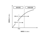
- FIG. 3 is a conceptual diagram for explaining the amplification characteristics of the amplification section 140.
- the horizontal axis represents input signal power, and the vertical axis represents output signal power.
- the amplification characteristic includes not only a linear region but also a nonlinear region, and the higher the input signal power, the stronger the influence of the nonlinear characteristic. Even if the average power is in the linear region, an input signal with a high PAPR (Peak to Average Power Ratio) is affected by nonlinear characteristics. As a result, distortion of the constellation of transmitted data may occur.
- PAPR Peak to Average Power Ratio
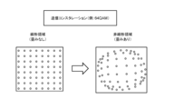
- FIG. 4 is a conceptual diagram for explaining constellation distortion of transmission data.
- a constellation of transmission data in the case of 64QAM is shown.
- the constellation is distorted in the nonlinear region.
- transmitting apparatus 100 precodes transmission data. Precoding with signal superposition tends to increase PAPR. Therefore, transmission data (transmission signal) with a high PAPR is input to amplification section 140, and may be affected by nonlinear characteristics and generate nonlinear distortion. When nonlinear distortion of transmitted data occurs, there is a risk of error-prone communication.
- the present embodiment provides a technique capable of reducing PAPR when transmitting apparatus 100 precodes transmission data.
- the present embodiment introduces a "phase shift" described below to reduce PAPR.
- FIG. 5 is a conceptual diagram for explaining the basics of the phase shift according to this embodiment.
- the modulation scheme is 64QAM.
- the modulation scheme is not limited to 64QAM.
- the transmission device 100 (modulation section 110) performs modulation processing for modulating transmission data using a predetermined modulation scheme.
- the transmitting apparatus 100 not only modulates the transmission data with a predetermined modulation scheme, but also adds a phase shift to the transmission data.
- the phase shift amount is ⁇ s. That is, in the modulation process, the transmitting apparatus 100 modulates the transmission data using a predetermined modulation method, and further shifts the phase of the transmission data according to the phase shift amount ⁇ s.
- FIG. 6 is a conceptual diagram for explaining the outline of the phase shift according to this embodiment.
- transmitting apparatus 100 transmits transmission data using multiple streams.
- the transmitting apparatus 100 determines the phase shift amount ⁇ s for each stream of transmission data, and performs the phase shift. That is, the phase shift amount ⁇ s is determined separately in the stream direction, and the phase shift is performed according to the phase shift amount ⁇ s for each stream.
- the phase shift amount ⁇ s for each stream is random. That is, transmitting apparatus 100 randomly determines phase shift amount ⁇ s for each stream of transmission data.
- FIG. 7 is a conceptual diagram for explaining an example of random phase shift according to this embodiment.
- a phase shift is performed in a predetermined data unit (eg, frame, slot).
- the phase shift amount ⁇ s is randomly determined for each stream.
- the phase shift amount ⁇ s for the first stream S1 is the first phase shift amount ⁇ 1
- the phase shift amount ⁇ s for the second stream S2 is the second phase shift amount ⁇ 2.
- the first phase shift amount ⁇ 1 and the second phase shift amount ⁇ 2 are different. The same applies when the number of streams is 3 or more.
- phase shift pattern PAT Information indicating the random phase shift amount ⁇ s for each stream is hereinafter referred to as "phase shift pattern PAT".
- Transmitter 100 acquires phase shift pattern PAT. Then, transmitting apparatus 100 determines a random phase shift amount ⁇ s for each stream based on phase shift pattern PAT. Thereafter, transmitting apparatus 100 performs modulation processing according to the determined random phase shift amount ⁇ s, and further performs subsequent processing.
- phase shift patterns PAT may be used.
- a plurality of types of phase shift patterns PAT indicate different random phase shift amounts ⁇ s.
- transmitting apparatus 100 selects one of a plurality of types of phase shift patterns PAT.
- transmitting apparatus 100 performs modulation processing using each of a plurality of types of phase shift patterns PAT, and further performs subsequent processing.
- Transmitting apparatus 100 then calculates the PAPR of the transmission data after precoding processing by precoding section 120, and selects one of the phase shift patterns PAT with the smallest PAPR from among the plurality of types of phase shift patterns PAT.
- transmitting apparatus 100 obtains information on reception quality (eg, BER (Bit Error Rate)) from receiving apparatus 200, and selects one of the phase shift patterns PAT with the highest reception quality. You can choose from Then, transmitting apparatus 100 determines a random phase shift amount ⁇ s for each stream based on one selected phase shift pattern PAT. Thereafter, transmitting apparatus 100 performs modulation processing according to the determined random phase shift amount ⁇ s, and further performs subsequent processing.
- reception quality eg, BER (Bit Error Rate)
- the range that the random phase shift amount ⁇ s can take can be freely set. After the random phase shift amount ⁇ s is generated, rounding to integers may be performed.
- FIG. 8 is a conceptual diagram for explaining "signal addition processing" according to the present embodiment.
- Receiving apparatus 200 needs to estimate the random phase shift amount ⁇ s applied to transmission data in transmitting apparatus 100 (that is, phase shift pattern PAT). Therefore, transmitting apparatus 100 adds a known signal for use in estimation by receiving apparatus 200 to each stream of transmission data. More specifically, transmitting apparatus 100 adds a known signal to the beginning or end of a predetermined data unit (eg, frame, slot).
- a known signal includes one or more symbols.
- the reception device 200 receives the transmission data transmitted from the transmission device 100 as reception data.
- Receiving apparatus 200 estimates a random phase shift amount ⁇ s (that is, phase shift pattern PAT) applied in transmitting apparatus 100 based on a known signal added to received data. Specifically, receiving apparatus 200 estimates the random phase shift amount ⁇ s by comparing the known signal added to the received data with the known signal held by itself. Then, receiving apparatus 200 demodulates the received data in consideration of the estimated phase shift amount ⁇ s. That is, when the receiving apparatus 200 demodulates the received data, the phase is returned by the phase shift amount ⁇ s for each stream included in the received data.
- ⁇ s that is, phase shift pattern PAT
- FIG. 9 is a conceptual diagram for explaining the effect of the phase shift according to this embodiment.
- the distribution of symbol sequences in the constellation approaches a circular shape due to the phase shift. Since the symbol phase that becomes the peak power is shifted, the peak power is reduced when the signal is superimposed by precoding. Furthermore, since zeros are not crossed when transitioning to symbols at point-symmetrical positions, the average power increases compared to the case where no phase shift is performed. In this way, PAPR can be reduced by performing a phase shift during modulation processing of transmission data.
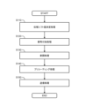
- FIG. 10 is a flow chart that summarizes the processing by transmitting device 100 according to the present embodiment.
- step S110 the transmission device 100 performs "phase shift amount determination processing". That is, transmitting apparatus 100 randomly determines phase shift amount ⁇ s for each stream of transmission data. More specifically, transmitting apparatus 100 obtains a phase shift pattern PAT indicating a random phase shift amount ⁇ s for each stream, and determines a random phase shift amount ⁇ s for each stream based on the phase shift pattern PAT.
- step S120 the transmission device 100 performs "signal addition processing" on the transmission data. More specifically, transmitting apparatus 100 adds a known signal used for estimating random phase shift amount ⁇ s in receiving apparatus 200 to each stream.
- step S130 the transmission device 100 performs "modulation processing" on the transmission data. More specifically, transmitting apparatus 100 modulates transmission data using a predetermined modulation scheme, and further shifts the phase of each stream according to the random phase shift amount ⁇ s. At this time, the known signal added to the transmission data is also phase-shifted.
- step S140 the transmission device 100 performs "precoding processing" on the transmission data. More specifically, transmitting apparatus 100 performs precoding on transmission data after modulation processing.
- step S150 the transmission device 100 performs "transmission processing" for transmitting transmission data after precoding processing from the transmission device to the reception device.
- the transmitting apparatus 100 may appropriately update the phase shift pattern PAT during communication. At the time of updating, the transmitting device 100 may reconsider all kinds of phase shift patterns PAT and select one out of all kinds of phase shift patterns PAT. Alternatively, transmitting apparatus 100 may reconsider only a certain number of phase shift patterns PAT that were relatively good last time, and select one of the certain number of phase shift patterns PAT.
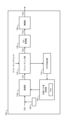
- FIG. 11 is a block diagram showing a first configuration example of the transmitting apparatus 100.
- the transmitting apparatus 100 includes a modulating section 110A, a precoding section 120, a D/A converting section 130, an amplifying section 140, a phase shift amount determining section 150, and a signal adding section 160.
- Modulation section 110A has a phase shift function in addition to the function of modulation section 110 shown in FIG.
- the precoding unit 120, the D/A converting unit 130, and the amplifying unit 140 are similar to those shown in FIG.
- phase shift amount determination unit 150 performs "phase shift amount determination processing". That is, phase shift amount determination section 150 determines a random phase shift amount ⁇ s for each stream of transmission data TD0.
- phase shift amount determination unit 150 acquires a phase shift pattern PAT indicating a random phase shift amount ⁇ s for each stream. Then, the phase shift amount determination section 150 determines a random phase shift amount ⁇ s for each stream based on the phase shift pattern PAT. Further, phase shift amount determination section 150 notifies modulation section 110A of random phase shift amount ⁇ s for each stream.
- the signal addition unit 160 performs "signal addition processing". More specifically, signal adding section 160 adds a known signal used for estimating random phase shift amount ⁇ s in receiving apparatus 200 to each stream (see FIG. 8). For example, the signal adding section 160 adds a known signal to the beginning or end of a predetermined data unit (eg, frame, slot).
- a predetermined data unit eg, frame, slot
- the modulation unit 110A receives information on the random phase shift amount ⁇ s for each stream from the phase shift amount determination unit 150. In the modulation process, the modulation section 110A modulates the transmission data TD0 with a predetermined modulation method, and further shifts the phase according to a random phase shift amount ⁇ s for each stream (see FIG. 7). At this time, the modulation section 110A also phase-shifts the added known signal. Modulation section 110A then outputs transmission data TD1 after modulation processing.
- FIG. 12 is a block diagram showing a second configuration example of the transmitting apparatus 100. As shown in FIG. Descriptions that overlap with the first configuration example shown in FIG. 11 are omitted as appropriate. Transmitting apparatus 100 further includes PAPR calculating section 170 in addition to the first configuration example shown in FIG.
- the phase shift amount determination unit 150 acquires multiple types of phase shift patterns PAT.
- a plurality of types of phase shift patterns PAT indicate different random phase shift amounts ⁇ s.
- the phase shift amount determination unit 150 provisionally selects a plurality of types of phase shift patterns PAT one by one.
- the phase shift amount determination unit 150 determines a random phase shift amount ⁇ s for each stream based on the temporarily selected phase shift pattern PAT. Then, phase shift amount determination section 150 notifies modulation section 110A of random phase shift amount ⁇ s for each stream.
- the modulation section 110A performs modulation processing in the same manner as in the case of the first configuration example.
- Precoding section 120 receives transmission data TD1 after modulation processing.
- Precoding section 120 precodes transmission data TD1 and outputs transmission data TD2.
- the PAPR calculation unit 170 receives transmission data TD2 after precoding processing.
- PAPR calculation section 170 calculates PAPR of transmission data TD2 in a predetermined data unit according to a predetermined calculation formula.
- PAPR calculation section 170 outputs calculated PAPR information to phase shift amount determination section 150 .
- the phase shift amount determination unit 150 acquires PAPR information for each of a plurality of types of phase shift patterns PAT. Then, the phase shift amount determining section 150 selects one of the phase shift patterns PAT with the minimum PAPR from the plurality of types of phase shift patterns PAT. The phase shift amount determination section 150 determines a random phase shift amount ⁇ s for each stream according to one selected phase shift pattern PAT. Phase shift amount determination section 150 then notifies modulation section 110A of the determined random phase shift amount ⁇ s for each stream. Thereafter, the modulation section 110A performs modulation processing using the random phase shift amount ⁇ s notified from the phase shift amount determination section 150. FIG.
- FIG. 13 is a block diagram showing a third configuration example of the transmission device 100. As shown in FIG. The description overlapping with the second configuration example shown in FIG. 12 will be omitted as appropriate.
- transmission device 100 includes reception quality information acquisition section 180 instead of PAPR calculation section 170 .
- Reception quality information acquisition section 180 acquires information on reception quality (eg, BER) of transmission data from receiving apparatus 200 .
- Reception quality information acquisition section 180 outputs reception quality information to phase shift amount determination section 150 .
- the phase shift amount determining section 150 acquires reception quality information for each of a plurality of types of phase shift patterns PAT. Then, phase shift amount determining section 150 selects one of the phase shift patterns PAT that provides the highest reception quality. The phase shift amount determination section 150 determines a random phase shift amount ⁇ s for each stream according to one selected phase shift pattern PAT. Phase shift amount determination section 150 then notifies modulation section 110A of the determined random phase shift amount ⁇ s for each stream. Thereafter, the modulation section 110A performs modulation processing using the random phase shift amount ⁇ s notified from the phase shift amount determination section 150. FIG.
- the transmission device 100 includes one or more processors (hereinafter simply referred to as “processors”) and one or more storage devices (hereinafter simply referred to as “storage devices”).
- processors hereinafter simply referred to as "processors”
- storage devices hereinafter simply referred to as “storage devices”.
- the processor includes a CPU (Central Processing Unit).
- the storage device stores various information necessary for processing by the processor. Examples of storage devices include volatile memory, nonvolatile memory, HDD (Hard Disk Drive), SSD (Solid State Drive), and the like.
- the processor may execute a control program, which is a computer program.
- the control program is stored in the storage device.
- the control program may be recorded on a computer-readable recording medium.
- the functions of the processor are realized by the processor executing the control program.
- phase shift patterns PAT prepared in advance Information on a plurality of types of phase shift patterns PAT prepared in advance is stored in the storage device.
- Functions such as modulation section 110A, precoding section 120, phase shift amount determination section 150, signal addition section 160, PAPR calculation section 170, reception quality information acquisition section 180, etc. are realized through cooperation between the processor and the storage device. .
- FIG. 14 is a block diagram showing a configuration example of the receiving device 200 .
- Receiver 200 includes amplifier 210 , A/D converter 220 , and demodulator 230 .
- the reception device 200 receives the transmission data transmitted from the transmission device 100 as reception data (reception signal) RD0.
- Amplifying section 210 amplifies received data RD0 and outputs received data RD1.
- A/D converter 220 A/D-converts received data RD1 and outputs received data RD2.
- the demodulator 230 performs "demodulation processing" for demodulating the received data RD2. At this time, the demodulator 230 demodulates the received data RD2 in consideration of the phase shift amount ⁇ s.
- demodulator 230 includes phase shift amount estimator 240 .
- Phase shift amount estimating section 240 estimates a random phase shift amount ⁇ s (that is, phase shift pattern PAT) applied in transmitting apparatus 100 based on the known signal added to received data RD2.
- the phase shift amount estimator 240 estimates the random phase shift amount ⁇ s by comparing the known signal added to the received data RD2 and the known signal held by itself.
- Demodulator 230 demodulates received data RD2 in consideration of the estimated phase shift amount ⁇ s. That is, the demodulator 230 demodulates the received data RD2 by a predetermined demodulation method, and returns the phase by the phase shift amount ⁇ s for each stream.
- the receiving device 200 includes one or more processors (hereinafter simply referred to as “processors”) and one or more storage devices (hereinafter simply referred to as “storage devices”).
- the processor may execute a control program, which is a computer program.
- the control program is stored in the storage device.
- the control program may be recorded on a computer-readable recording medium.
- the functions of the processor are realized by the processor executing the control program. Functions such as the demodulator 230 and the phase shift amount estimator 240 are realized by cooperation between the processor and the storage device.
- Radio Communication System 100 Transmitter 110, 110A Modulator 120 Precoder 130 D/A Converter 140 Amplifier 150 Phase Shift Amount Determiner 160 Signal Adder 170 PAPR Calculator 180 Reception Quality Information Acquirer 200 Receiver 210 Amplification Part 220 A/D converter 230 Demodulator 240 Phase shift amount estimator PAT Phase shift pattern
Landscapes
- Engineering & Computer Science (AREA)
- Computer Networks & Wireless Communication (AREA)
- Signal Processing (AREA)
- Digital Transmission Methods That Use Modulated Carrier Waves (AREA)
Abstract
Description
無線通信方法は、
送信データのストリーム毎にランダムな位相シフト量を決定する位相シフト量決定処理と、
送信データを変調すると共に、ストリーム毎にランダムな位相シフト量に従って位相を更にシフトする変調処理と、
変調処理後の送信データに対してプリコーディングを行うプリコーディング処理と、
プリコーディング処理後の送信データを送信装置から受信装置に送信する送信処理と
を含む。 A first aspect relates to a wireless communication method for performing wireless communication between a transmitting device and a receiving device.
The wireless communication method is
A phase shift amount determination process for determining a random phase shift amount for each stream of transmission data;
A modulation process that modulates transmission data and further shifts the phase according to a random phase shift amount for each stream;
precoding processing for precoding transmission data after modulation processing;
and transmission processing for transmitting transmission data after precoding processing from a transmission device to a reception device.
無線通信システムは、送信装置と受信装置とを備える。
送信装置は、
送信データのストリーム毎にランダムな位相シフト量を決定する位相シフト量決定処理と、
送信データを変調すると共に、ストリーム毎にランダムな位相シフト量に従って位相を更にシフトする変調処理と、
変調処理後の送信データに対してプリコーディングを行うプリコーディング処理と、
プリコーディング処理後の送信データを送信装置から受信装置に送信する送信処理と
を実行する。 A second aspect relates to wireless communication systems.
A wireless communication system includes a transmitter and a receiver.
The transmitting device
A phase shift amount determination process for determining a random phase shift amount for each stream of transmission data;
A modulation process that modulates transmission data and further shifts the phase according to a random phase shift amount for each stream;
precoding processing for precoding transmission data after modulation processing;
and a transmission process of transmitting the transmission data after the precoding process from the transmission device to the reception device.
送信装置は、
送信データのストリーム毎にランダムな位相シフト量を決定する位相シフト量決定部と、
前記送信データを変調すると共に、前記ストリーム毎に前記ランダムな位相シフト量に従って位相を更にシフトする変調部と、
前記変調処理後の前記送信データに対してプリコーディングを行うプリコーディング部と、
前記プリコーディング処理後の前記送信データを前記受信装置に送信する送信部と
を備える。 A third aspect relates to a transmitting device that wirelessly communicates with a receiving device.
The transmitting device
a phase shift amount determination unit that determines a random phase shift amount for each stream of transmission data;
a modulation unit that modulates the transmission data and further shifts the phase according to the random phase shift amount for each stream;
a precoding unit that precodes the transmission data after the modulation process;
and a transmitting unit configured to transmit the transmission data after the precoding process to the receiving device.
図1は、本実施の形態に係る無線通信システム1の構成を概略的に示す概念図である。無線通信システム1は、送信装置100と受信装置200を含んでいる。送信装置100と受信装置200は、無線通信を行う。無線通信システム1は、MIMO(Multiple-Input Multiple-Output)システムであってもよいし、SISO(Single-Input Single-Output)システムであってもよいし、その他であってもよい。無線通信システム1は、シングルキャリア伝送を行ってもよいし、OFDM(Orthogonal Frequency Division Multiplexing)等に基づくマルチキャリア伝送を行ってもよい。 1. Overview of Radio Communication System FIG. 1 is a conceptual diagram schematically showing the configuration of a radio communication system 1 according to this embodiment. A wireless communication system 1 includes a
図5は、本実施の形態に係る位相シフトの基本を説明するための概念図である。ここでは、一例として、変調方式が64QAMの場合が示されている。但し、変調方式は64QAMに限定されない。 2. PAPR Reduction Using Phase Shift FIG. 5 is a conceptual diagram for explaining the basics of the phase shift according to this embodiment. Here, as an example, a case where the modulation scheme is 64QAM is shown. However, the modulation scheme is not limited to 64QAM.
以下、送信装置100及び受信装置200の構成例について説明する。 3. Configuration Example Configuration examples of the
3-1-1.第1の構成例
図11は、送信装置100の第1の構成例を示すブロック図である。送信装置100は、変調部110A、プリコーディング部120、D/A変換部130、増幅部140、位相シフト量決定部150、及び信号付加部160を含んでいる。変調部110Aは、図2で示された変調部110の機能に加えて、位相シフト機能を備えている。プリコーディング部120、D/A変換部130、及び増幅部140は、図2で示されたものと同様である。 3-1. Configuration example of transmitter 3-1-1. First Configuration Example FIG. 11 is a block diagram showing a first configuration example of the transmitting
図12は、送信装置100の第2の構成例を示すブロック図である。図11で示された第1の構成例と重複する説明は適宜省略される。送信装置100は、図11で示された第1の構成例に加えて、PAPR算出部170を更に含んでいる。 3-1-2. Second Configuration Example FIG. 12 is a block diagram showing a second configuration example of the transmitting
図13は、送信装置100の第3の構成例を示すブロック図である。図12で示された第2の構成例と重複する説明は適宜省略される。 3-1-3. Third Configuration Example FIG. 13 is a block diagram showing a third configuration example of the
送信装置100は、1又は複数のプロセッサ(以下、単に「プロセッサ」と呼ぶ)と1又は複数の記憶装置(以下、単に「記憶装置」と呼ぶ)を含んでいる。例えば、プロセッサは、CPU(Central Processing Unit)を含んでいる。記憶装置は、プロセッサによる処理に必要な各種情報を格納する。記憶装置としては、揮発性メモリ、不揮発性メモリ、HDD(Hard Disk Drive)、SSD(Solid State Drive)、等が例示される。 3-1-4. Hardware Configuration Example The
図14は、受信装置200の構成例を示すブロック図である。受信装置200は、増幅部210、A/D変換部220、復調部230を含んでいる。 3-2. Configuration Example of Receiving Device FIG. 14 is a block diagram showing a configuration example of the receiving
100 送信装置
110,110A 変調部
120 プリコーディング部
130 D/A変換部
140 増幅部
150 位相シフト量決定部
160 信号付加部
170 PAPR算出部
180 受信品質情報取得部
200 受信装置
210 増幅部
220 A/D変換部
230 復調部
240 位相シフト量推定部
PAT 位相シフトパターン 1
Claims (8)
- 送信装置と受信装置との間で無線通信を行う無線通信方法であって、
送信データのストリーム毎にランダムな位相シフト量を決定する位相シフト量決定処理と、
前記送信データを変調すると共に、前記ストリーム毎に前記ランダムな位相シフト量に従って位相を更にシフトする変調処理と、
前記変調処理後の前記送信データに対してプリコーディングを行うプリコーディング処理と、
前記プリコーディング処理後の前記送信データを前記送信装置から前記受信装置に送信する送信処理と
を含む
無線通信方法。 A wireless communication method for performing wireless communication between a transmitting device and a receiving device,
A phase shift amount determination process for determining a random phase shift amount for each stream of transmission data;
a modulation process that modulates the transmission data and further shifts the phase according to the random phase shift amount for each stream;
precoding processing for precoding the transmission data after the modulation processing;
a transmission process of transmitting the transmission data after the precoding process from the transmission device to the reception device. - 請求項1に記載の無線通信方法であって、
前記位相シフト決定処理は、
前記ストリーム毎の前記ランダムな位相シフト量を示す位相シフトパターンを取得することと、
前記位相シフトパターンに基づいて、前記ストリーム毎の前記ランダムな位相シフト量を決定することを含む
無線通信方法。 The wireless communication method according to claim 1,
The phase shift determination process includes:
obtaining a phase shift pattern indicating the random phase shift amount for each stream;
A wireless communication method, comprising determining the random phase shift amount for each of the streams based on the phase shift pattern. - 請求項2に記載の無線通信方法であって、
前記位相シフト量決定処理は、
複数種類の位相シフトパターンを取得することと、
前記複数種類の位相シフトパターンの中から、前記プリコーディング処理後の前記送信データのPAPR(Peak to Average Power Ratio)が最小となる1つ、あるいは、前記受信装置における前記送信データの受信品質が最高となる1つを選択することと、
前記選択された位相シフトパターンに基づいて、前記ストリーム毎の前記ランダムな位相シフト量を決定することと
を含む
無線通信方法。 The wireless communication method according to claim 2,
The phase shift amount determination process includes:
obtaining a plurality of types of phase shift patterns;
One of the plurality of types of phase shift patterns that has the lowest PAPR (Peak to Average Power Ratio) of the transmission data after the precoding process, or the reception quality of the transmission data at the receiving device is the highest. selecting one that is
determining the random amount of phase shift for each stream based on the selected phase shift pattern. - 請求項1乃至3のいずれか一項に記載の無線通信方法であって、
前記受信装置において前記ランダムな位相シフト量を推定するために用いられる既知信号を前記送信データの前記ストリームに付加する信号付加処理を更に含む
無線通信方法。 The wireless communication method according to any one of claims 1 to 3,
A wireless communication method, further comprising a signal adding process of adding a known signal used for estimating the random phase shift amount in the receiving device to the stream of the transmission data. - 請求項4に記載の無線通信方法であって、
前記送信装置から送信された前記送信データを前記受信装置において受信データとして受信する処理と、
前記受信装置において前記既知信号に基づいて前記ランダムな位相シフト量を推定する処理と、
前記推定された位相シフト量に基づいて前記受信データの復調を行う復調処理と
を更に含む
無線通信方法。 The wireless communication method according to claim 4,
a process of receiving the transmission data transmitted from the transmission device as reception data in the reception device;
A process of estimating the random phase shift amount based on the known signal in the receiving device;
A radio communication method, further comprising demodulation processing for demodulating the received data based on the estimated phase shift amount. - 送信装置と、
受信装置と
を備え、
前記送信装置は、
送信データのストリーム毎にランダムな位相シフト量を決定する位相シフト量決定処理と、
前記送信データを変調すると共に、前記ストリーム毎に前記ランダムな位相シフト量に従って位相を更にシフトする変調処理と、
前記変調処理後の前記送信データに対してプリコーディングを行うプリコーディング処理と、
前記プリコーディング処理後の前記送信データを前記送信装置から前記受信装置に送信する送信処理と
を実行する
無線通信システム。 a transmitting device;
a receiving device and
The transmitting device
A phase shift amount determination process for determining a random phase shift amount for each stream of transmission data;
a modulation process that modulates the transmission data and further shifts the phase according to the random phase shift amount for each stream;
precoding processing for precoding the transmission data after the modulation processing;
and a transmission process of transmitting the transmission data after the precoding process from the transmission device to the reception device. - 請求項6に記載の無線通信システムであって、
前記送信装置は、更に、前記受信装置において前記ランダムな位相シフト量を推定するために用いられる既知信号を前記送信データの前記ストリームに付加する信号付加処理を実行し、
前記受信装置は、
前記送信装置から送信された前記送信データを受信データとして受信し、
前記既知信号に基づいて前記ランダムな位相シフト量を推定し、
前記推定された位相シフト量に基づいて前記受信データの復調を行う
無線通信システム。 A wireless communication system according to claim 6,
The transmitting device further performs a signal addition process of adding a known signal used for estimating the random phase shift amount in the receiving device to the stream of the transmission data,
The receiving device
receiving the transmission data transmitted from the transmission device as reception data;
estimating the random phase shift amount based on the known signal;
A wireless communication system that demodulates the received data based on the estimated phase shift amount. - 受信装置と無線通信を行う送信装置であって、
送信データのストリーム毎にランダムな位相シフト量を決定する位相シフト量決定部と、
前記送信データを変調すると共に、前記ストリーム毎に前記ランダムな位相シフト量に従って位相を更にシフトする変調部と、
前記変調処理後の前記送信データに対してプリコーディングを行うプリコーディング部と、
前記プリコーディング処理後の前記送信データを前記受信装置に送信する送信部と
を備える
送信装置。 A transmitting device that performs wireless communication with a receiving device,
a phase shift amount determination unit that determines a random phase shift amount for each stream of transmission data;
a modulation unit that modulates the transmission data and further shifts the phase according to the random phase shift amount for each stream;
a precoding unit that precodes the transmission data after the modulation process;
A transmitter that transmits the transmission data after the precoding process to the receiver.
Priority Applications (2)
| Application Number | Priority Date | Filing Date | Title |
|---|---|---|---|
| PCT/JP2022/006202 WO2023157133A1 (en) | 2022-02-16 | 2022-02-16 | Wireless communication method, wireless communication system, and transmission device |
| JP2024500775A JPWO2023157133A1 (en) | 2022-02-16 | 2022-02-16 |
Applications Claiming Priority (1)
| Application Number | Priority Date | Filing Date | Title |
|---|---|---|---|
| PCT/JP2022/006202 WO2023157133A1 (en) | 2022-02-16 | 2022-02-16 | Wireless communication method, wireless communication system, and transmission device |
Publications (1)
| Publication Number | Publication Date |
|---|---|
| WO2023157133A1 true WO2023157133A1 (en) | 2023-08-24 |
Family
ID=87577848
Family Applications (1)
| Application Number | Title | Priority Date | Filing Date |
|---|---|---|---|
| PCT/JP2022/006202 WO2023157133A1 (en) | 2022-02-16 | 2022-02-16 | Wireless communication method, wireless communication system, and transmission device |
Country Status (2)
| Country | Link |
|---|---|
| JP (1) | JPWO2023157133A1 (en) |
| WO (1) | WO2023157133A1 (en) |
Citations (2)
| Publication number | Priority date | Publication date | Assignee | Title |
|---|---|---|---|---|
| JP2009194732A (en) * | 2008-02-15 | 2009-08-27 | Ntt Docomo Inc | Wireless communication device and wireless communication method |
| JP2021048637A (en) * | 2010-12-10 | 2021-03-25 | サン パテント トラスト | Signal generation method and signal generation device |
-
2022
- 2022-02-16 WO PCT/JP2022/006202 patent/WO2023157133A1/en active Application Filing
- 2022-02-16 JP JP2024500775A patent/JPWO2023157133A1/ja active Pending
Patent Citations (2)
| Publication number | Priority date | Publication date | Assignee | Title |
|---|---|---|---|---|
| JP2009194732A (en) * | 2008-02-15 | 2009-08-27 | Ntt Docomo Inc | Wireless communication device and wireless communication method |
| JP2021048637A (en) * | 2010-12-10 | 2021-03-25 | サン パテント トラスト | Signal generation method and signal generation device |
Non-Patent Citations (2)
| Title |
|---|
| ISHIDA, YUSUKE ET AL.: "B-5-77 PAPR Reduction by Subcarrier-Phase Hopping for MIMO-OFDM with Large Number of Subcarriers", PROCEEDINGS OF THE 2007 IEICE SOCIETY CONFERENCE (1); 2007.09.10-14, IEICE, JP, 29 August 2007 (2007-08-29) - 14 September 2007 (2007-09-14), JP, pages 399, XP009548330 * |
| KURIYAMA ET AL.: "PAPR Reduction on Wideband Single-Carrier MIMO Systems with Variable Tap-Length FIR Beamforming", SOCIETY CONFERENCE OF THE INSTITUTE OF ELECTRONICS, INFORMATION AND COMMUNICATION ENGINEERS, September 2021 (2021-09-01), pages B-5 - 70 |
Also Published As
| Publication number | Publication date |
|---|---|
| JPWO2023157133A1 (en) | 2023-08-24 |
Similar Documents
| Publication | Publication Date | Title |
|---|---|---|
| JP6799110B2 (en) | Preamble for nonlinearity estimation | |
| JP5377639B2 (en) | Mobile station apparatus, base station apparatus, communication system, communication method, and control program | |
| JP4911780B2 (en) | Wireless communication system, receiving apparatus and receiving method | |
| JP6577800B2 (en) | Single carrier transmission device and reception device | |
| US20090161784A1 (en) | Transmit power allocation for adaptive multi-carrier multiplexing mimo systems | |
| US20100208676A1 (en) | Signal Transmission Method and Apparatus for OFDMA Wireless Communication System | |
| JP4331221B2 (en) | Wireless communication method, wireless transmission device, and wireless reception device | |
| US20150010104A1 (en) | Transmitter and signal transmitting method thereof | |
| CN104272691A (en) | Signaling to support advanced wireless receivers and related devices and methods | |
| WO2010104006A1 (en) | Mobile station device, communications system, communications method, and program | |
| US20080240273A1 (en) | Radio transmitting apparatus and radio receiving apparatus using ofdm | |
| JP2008206045A (en) | Radio communication system and dadio device | |
| US11522584B2 (en) | Transmission method and transmission device | |
| JP4279646B2 (en) | Communication device | |
| WO2023157133A1 (en) | Wireless communication method, wireless communication system, and transmission device | |
| WO2023157132A1 (en) | Wireless communication method, wireless communication system, and transmission device | |
| US20210359727A1 (en) | Wireless communication system, wireless communication method, transmitting station device and receiving station device | |
| WO2023144879A1 (en) | Wireless communication method, wireless communication system, and transmission device | |
| WO2023157143A1 (en) | Wireless communication method, wireless communication system, and transmission device | |
| WO2023144882A1 (en) | Wireless communication method, wireless communication system, and transmission device | |
| WO2023144887A1 (en) | Wireless communication method, wireless communication system, and transmission device | |
| JP5333608B2 (en) | Compound condition judging unit, transmission device, compound condition judging method | |
| WO2023032160A1 (en) | Wireless communication system, wireless communication method, and wireless communication transmission device | |
| JP4177879B1 (en) | Reception device, transmission device, and wireless communication system | |
| WO2023026492A1 (en) | Wireless communication method, wireless communication system, and transmission device |
Legal Events
| Date | Code | Title | Description |
|---|---|---|---|
| 121 | Ep: the epo has been informed by wipo that ep was designated in this application |
Ref document number: 22927036 Country of ref document: EP Kind code of ref document: A1 |
|
| ENP | Entry into the national phase |
Ref document number: 2024500775 Country of ref document: JP Kind code of ref document: A |
|
| WWE | Wipo information: entry into national phase |
Ref document number: 2022927036 Country of ref document: EP |
|
| ENP | Entry into the national phase |
Ref document number: 2022927036 Country of ref document: EP Effective date: 20240916 |