WO2023144887A1 - Wireless communication method, wireless communication system, and transmission device - Google Patents
Wireless communication method, wireless communication system, and transmission device Download PDFInfo
- Publication number
- WO2023144887A1 WO2023144887A1 PCT/JP2022/002671 JP2022002671W WO2023144887A1 WO 2023144887 A1 WO2023144887 A1 WO 2023144887A1 JP 2022002671 W JP2022002671 W JP 2022002671W WO 2023144887 A1 WO2023144887 A1 WO 2023144887A1
- Authority
- WO
- WIPO (PCT)
- Prior art keywords
- phase shift
- transmission data
- shift amount
- precoding
- transmission
- Prior art date
Links
Images


Classifications
-
- H—ELECTRICITY
- H04—ELECTRIC COMMUNICATION TECHNIQUE
- H04L—TRANSMISSION OF DIGITAL INFORMATION, e.g. TELEGRAPHIC COMMUNICATION
- H04L27/00—Modulated-carrier systems
- H04L27/26—Systems using multi-frequency codes
Definitions
- the present invention relates to wireless communication technology.
- the present invention relates to a radio communication technique in which transmission data is precoded on the transmitting side.
- the transmitting side may precode the transmitted data. For example, when performing wideband transmission under a frequency selective fading environment, channel equalization is performed by precoding. As another example, multiple-input multiple-output (MIMO) systems perform stream separation by precoding.
- MIMO multiple-input multiple-output
- PAPR Peak to Average Power Ratio
- a transmission signal is amplified by a power amplifier before being transmitted from an antenna, and if a signal with a high PAPR is input to the power amplifier, it may be affected by the nonlinear characteristics of the power amplifier and cause nonlinear distortion. The occurrence of nonlinear distortion in the transmitted signal may result in erroneous communication.
- Non-Patent Document 1 discloses a technique for reducing PAPR in a wideband single-carrier MIMO system.
- the PAPR increases.
- One object of the present invention is to provide a technique capable of reducing PAPR when the transmission side precodes transmission data in wireless communication.
- a first aspect relates to a wireless communication method for performing wireless communication between a transmitting device and a receiving device.
- the wireless communication method is A phase shift amount determination process for determining a phase shift amount for each subcarrier of transmission data; A modulation process for modulating transmission data and further shifting the phase according to the phase shift amount for each subcarrier; precoding processing for precoding transmission data after modulation processing; and transmission processing for transmitting transmission data after precoding processing from a transmission device to a reception device.
- a plurality of types of phase shift patterns prepared in advance define different phase shift amounts.
- the phase shift amount determination process is Selecting, from among a plurality of types of phase shift patterns, one that minimizes the PAPR of transmission data after precoding processing or one that maximizes the reception quality of transmission data in a receiving device; determining the amount of phase shift for each subcarrier according to the selected phase shift pattern.
- a second aspect relates to wireless communication systems.
- a wireless communication system includes a transmitter and a receiver.
- the transmitting device A phase shift amount determination process for determining a phase shift amount for each subcarrier of transmission data; A modulation process for modulating transmission data and further shifting the phase according to the phase shift amount for each subcarrier; precoding processing for precoding transmission data after modulation processing; and transmission processing for transmitting transmission data after precoding processing to a receiving device.
- a plurality of types of phase shift patterns prepared in advance define different phase shift amounts.
- the phase shift amount determination process is Selecting, from among a plurality of types of phase shift patterns, one that minimizes the PAPR of transmission data after precoding processing or one that maximizes the reception quality of transmission data in a receiving device; determining the amount of phase shift for each subcarrier according to the selected phase shift pattern.
- a third aspect relates to a transmitting device that wirelessly communicates with a receiving device.
- the transmitting device a phase shift amount determining unit that determines a phase shift amount for each subcarrier of transmission data; a modulation unit that modulates transmission data and further shifts the phase according to the phase shift amount for each subcarrier; a precoding unit that precodes transmission data after modulation processing; a transmitting unit configured to transmit transmission data after precoding processing to a receiving device.
- a plurality of types of phase shift patterns prepared in advance define different phase shift amounts.
- the phase shift amount determining unit selects, from among a plurality of types of phase shift patterns, one that minimizes the PAPR of transmission data after precoding processing, or one that maximizes the reception quality of transmission data in a receiving device. select. Then, the phase shift amount determining section determines the phase shift amount for each subcarrier according to the selected phase shift pattern.
- the present invention it is possible to reduce the PAPR when the transmission side performs precoding on transmission data in wireless communication.
- FIG. 1 is a conceptual diagram schematically showing the configuration of a radio communication system according to an embodiment
- FIG. FIG. 2 is a block diagram showing a basic configuration example of a transmission device that performs precoding
- FIG. 4 is a conceptual diagram for explaining amplification characteristics of an amplifier
- FIG. 4 is a conceptual diagram for explaining distortion of constellation
- FIG. 4 is a conceptual diagram for explaining the basics of phase shift according to the embodiment
- FIG. 4 is a conceptual diagram for explaining an overview of phase shift according to the embodiment
- FIG. 4 is a conceptual diagram for explaining an example of a phase shift pattern according to the embodiment
- FIG. 4 is a conceptual diagram for explaining signal addition processing according to the embodiment
- FIG. 4 is a conceptual diagram for explaining the effect of phase shift according to the embodiment; 4 is a flow chart summarizing processing by a transmitting device according to an embodiment; 1 is a block diagram showing a first configuration example of a transmission device according to an embodiment; FIG. FIG. 10 is a block diagram showing a second configuration example of a transmission device according to an embodiment; 1 is a block diagram showing a configuration example of a receiving device according to an embodiment; FIG.
- FIG. 1 is a conceptual diagram schematically showing the configuration of a radio communication system 1 according to this embodiment.
- a wireless communication system 1 includes a transmitter 100 and a receiver 200 .
- the transmitting device 100 and the receiving device 200 perform wireless communication.
- the radio communication system 1 may be a MIMO (Multiple-Input Multiple-Output) system, a SISO (Single-Input Single-Output) system, or others.
- the radio communication system 1 may perform single-carrier transmission, or may perform multi-carrier transmission based on OFDM (Orthogonal Frequency Division Multiplexing) or the like.
- OFDM Orthogonal Frequency Division Multiplexing
- the transmission device 100 precodes the transmission data. Precoding is a well known technique. For example, when performing wideband transmission under a frequency selective fading environment, channel equalization is performed by precoding. As another example, in MIMO systems, stream separation is performed by precoding.
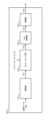
- FIG. 2 is a block diagram showing a basic configuration example of the transmission device 100 that performs precoding.
- Transmitting apparatus 100 includes modulating section 110 , precoding section 120 , D/A converting section 130 and amplifying section 140 .
- the modulation section 110 receives transmission data (transmission signal) TD0 transmitted from the transmission device 100 to the reception device 200 .
- Modulation section 110 performs “modulation processing” for modulating transmission data TD0 using a predetermined modulation scheme. Examples of the predetermined modulation scheme include QAM (Quadrature Amplitude Modulation), QPSK (Quadrature Phase Shift Keying), and the like.
- Modulation section 110 outputs transmission data TD1 after modulation processing.
- the precoding section 120 receives transmission data TD1 after modulation processing.
- the precoding unit 120 performs a “precoding process” for precoding transmission data TD1.
- Various examples are known as precoding weights (precoding matrices) used in precoding processing. In this embodiment, precoding weights are not particularly limited.
- Precoding section 120 outputs transmission data TD2 after precoding processing.
- the D/A converter 130 receives transmission data TD2 after precoding processing.
- D/A converter 130 D/A converts transmission data TD2 and outputs transmission data TD3.
- the amplification unit 140 receives transmission data TD3 after D/A conversion.
- Amplification section 140 includes a power amplifier, and performs “amplification processing” for amplifying transmission data TD3.
- the amplification section 140 performs a "transmission process" for transmitting the amplified transmission data (transmission signal) TD4 to the receiving device 200 via the antenna.
- the amplification unit 140 also functions as a “transmission unit” that performs transmission processing.
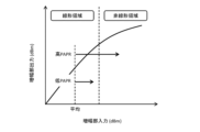
- FIG. 3 is a conceptual diagram for explaining the amplification characteristics of the amplification section 140.
- the horizontal axis represents input signal power, and the vertical axis represents output signal power.
- the amplification characteristic includes not only a linear region but also a nonlinear region, and the higher the input signal power, the stronger the influence of the nonlinear characteristic. Even if the average power is in the linear region, an input signal with a high PAPR (Peak to Average Power Ratio) is affected by nonlinear characteristics. As a result, distortion of the constellation of transmitted data may occur.
- PAPR Peak to Average Power Ratio
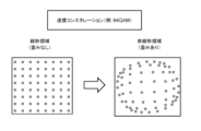
- FIG. 4 is a conceptual diagram for explaining constellation distortion of transmission data.
- a constellation of transmission data in the case of 64QAM is shown.
- the constellation is distorted in the nonlinear region.
- transmitting apparatus 100 precodes transmission data. Precoding with signal superposition tends to increase PAPR. Therefore, transmission data (transmission signal) with a high PAPR is input to amplification section 140, and may be affected by nonlinear characteristics and generate nonlinear distortion. When nonlinear distortion of transmitted data occurs, there is a risk of error-prone communication.
- the present embodiment provides a technique capable of reducing PAPR when transmitting apparatus 100 precodes transmission data.
- the present embodiment introduces a "phase shift" described below to reduce PAPR.
- FIG. 5 is a conceptual diagram for explaining the basics of the phase shift according to this embodiment.
- the modulation scheme is 64QAM.
- the modulation scheme is not limited to 64QAM.
- the transmission device 100 (modulation section 110) performs modulation processing for modulating transmission data using a predetermined modulation scheme.
- the transmitting apparatus 100 not only modulates the transmission data with a predetermined modulation scheme, but also adds a phase shift to the transmission data.
- the phase shift amount is ⁇ s. That is, in the modulation process, the transmitting apparatus 100 modulates the transmission data using a predetermined modulation method, and further shifts the phase of the transmission data according to the phase shift amount ⁇ s.
- FIG. 6 is a conceptual diagram for explaining the outline of the phase shift according to this embodiment.
- the transmitting apparatus 100 performs multicarrier transmission based on OFDM or the like.
- the phase shift amount ⁇ s is determined for each subcarrier of transmission data, and phase shift is performed. That is, the phase shift amount ⁇ s is determined separately for each subcarrier in the frequency direction, and the phase shift is performed according to the phase shift amount ⁇ s for each subcarrier.
- phase shift pattern PAT that defines the phase shift amount ⁇ s for each subcarrier is prepared in advance.
- the phase shift pattern PAT defines the phase shift amount ⁇ s for each subcarrier such that the phase shift amount ⁇ s differs between two or more subcarriers.
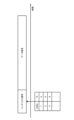
- FIG. 7 is a conceptual diagram for explaining an example of the phase shift pattern PAT according to this embodiment.
- Phase shift processing is performed in predetermined data units (eg, frames, slots).
- FFT Fast Fourier Transform
- the phase shift amount ⁇ s is determined separately for each subcarrier.
- the parameter N is an integer other than 0.
- the phase shift amount ⁇ s sequentially differs by a constant amount ( ⁇ /N) between the subcarriers Si.
- a plurality of types of phase shift patterns PAT are prepared in advance.
- a plurality of types of phase shift patterns PAT define different phase shift amounts ⁇ s.
- N e.g. 4, 6, 8, . . .
- a different index is given to each of the plurality of types of phase shift patterns PAT.
- Transmitting device 100 selects one from a plurality of types of phase shift patterns PAT. For example, transmitting apparatus 100 performs modulation processing using each of a plurality of types of phase shift patterns PAT, and further performs subsequent processing. Transmitting apparatus 100 then calculates the PAPR of the transmission data after precoding processing by precoding section 120, and selects one of the phase shift patterns PAT with the smallest PAPR from among the plurality of types of phase shift patterns PAT. As another example, transmitting apparatus 100 obtains information on reception quality (eg, BER (Bit Error Rate)) from receiving apparatus 200, and selects one of the phase shift patterns PAT with the highest reception quality. You can choose from reception quality (eg, BER (Bit Error Rate)) from receiving apparatus 200, and selects one of the phase shift patterns PAT with the highest reception quality. You can choose from reception quality (eg, BER (Bit Error Rate)) from receiving apparatus 200, and selects one of the phase shift patterns PAT with the highest reception quality. You can choose from
- transmitting apparatus 100 determines phase shift amount ⁇ s for each subcarrier of transmission data according to one selected phase shift pattern PAT. Thereafter, transmitting apparatus 100 performs modulation processing according to the determined phase shift amount ⁇ s, and further performs subsequent processing.
- FIG. 8 is a conceptual diagram for explaining "signal addition processing" according to the present embodiment.
- Transmitter 100 adds an index signal (control signal) indicating one selected phase shift pattern PAT to transmission data. More specifically, transmitting apparatus 100 adds an index signal to the beginning or end of a predetermined data unit (eg, frame, slot).
- a predetermined data unit eg, frame, slot
- the reception device 200 receives the transmission data transmitted from the transmission device 100 as reception data.
- Receiving apparatus 200 can recognize the phase shift pattern PAT applied to a predetermined data unit based on the index signal added to the received data.
- Receiving apparatus 200 demodulates the received data in consideration of the phase shift pattern PAT applied to the data unit. That is, when receiving apparatus 200 demodulates the received data, the phase is returned by the phase shift amount ⁇ s for each subcarrier of the received data.
- FIG. 9 is a conceptual diagram for explaining the effect of the phase shift according to this embodiment.
- the distribution of symbol sequences in the constellation approaches a circular shape due to the phase shift. Since the symbol phase that becomes the peak power is shifted, the peak power is reduced when the signal is superimposed by precoding. Furthermore, since zeros are not crossed when transitioning to symbols at point-symmetrical positions, the average power increases compared to the case where no phase shift is performed. In this way, PAPR can be reduced by performing a phase shift during modulation processing of transmission data.
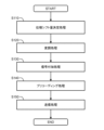
- FIG. 10 is a flow chart that summarizes the processing by transmitting device 100 according to the present embodiment.
- step S110 the transmission device 100 performs "phase shift amount determination processing". That is, transmitting apparatus 100 determines phase shift amount ⁇ s for each subcarrier of transmission data. More specifically, transmitting apparatus 100 selects one of a plurality of types of phase shift patterns PAT prepared in advance. For example, transmitting apparatus 100 selects one of a plurality of types of phase shift patterns PAT that minimizes the PAPR of transmission data after precoding processing. As another example, transmitting apparatus 100 may select one of a plurality of types of phase shift patterns PAT that maximizes the reception quality of transmission data in receiving apparatus 200 . Then, transmitting apparatus 100 determines phase shift amount ⁇ s for each subcarrier according to the selected phase shift pattern PAT.
- step S120 the transmission device 100 performs "modulation processing" on the transmission data. More specifically, transmitting apparatus 100 modulates transmission data using a predetermined modulation scheme, and further shifts the phase according to the phase shift amount ⁇ s for each subcarrier.
- step S130 the transmission device 100 performs "signal addition processing" on the transmission data. More specifically, transmitting apparatus 100 adds an index signal (control signal) indicating one selected phase shift pattern PAT to transmission data.
- step S140 the transmission device 100 performs "precoding processing" on the transmission data. More specifically, transmitting apparatus 100 performs precoding on transmission data after modulation processing.
- step S150 the transmission device 100 performs "transmission processing" for transmitting transmission data after precoding processing from the transmission device to the reception device.
- the transmitting apparatus 100 may appropriately update the phase shift pattern PAT during communication. At the time of updating, the transmitting device 100 may reconsider all kinds of phase shift patterns PAT and select one out of all kinds of phase shift patterns PAT. Alternatively, transmitting apparatus 100 may reconsider only a certain number of phase shift patterns PAT that were relatively good last time, and select one of the certain number of phase shift patterns PAT.
- FIG. 11 is a block diagram showing a first configuration example of the transmitting apparatus 100.
- the transmitting apparatus 100 includes a modulating section 110A, a precoding section 120, a D/A converting section 130, an amplifying section 140, a phase shift amount determining section 150, a signal adding section 160, and a PAPR calculating section 170.
- Modulation section 110A has a phase shift function in addition to the function of modulation section 110 shown in FIG.
- the precoding unit 120, the D/A converting unit 130, and the amplifying unit 140 are similar to those shown in FIG.
- the phase shift amount determination unit 150 performs "phase shift amount determination processing". That is, the phase shift amount determining section 150 determines the phase shift amount ⁇ s for each subcarrier of the transmission data TD0.
- the phase shift amount determination unit 150 holds information on a plurality of types of phase shift patterns PAT prepared in advance.
- a plurality of types of phase shift patterns PAT define different phase shift amounts ⁇ s.
- the phase shift amount determination unit 150 provisionally selects a plurality of types of phase shift patterns PAT one by one.
- Phase shift amount determination section 150 notifies modulation section 110A of phase shift amount ⁇ s for each subcarrier defined by the temporarily selected phase shift pattern PAT.
- the modulating section 110A receives information on the phase shift amount ⁇ s for each subcarrier from the phase shift amount determining section 150 .
- the modulation section 110A modulates the transmission data TD0 with a predetermined modulation method, and further shifts the phase according to the phase shift amount ⁇ s for each subcarrier (see FIG. 7).
- Modulation section 110A outputs transmission data TD1 after modulation processing.
- the precoding section 120 receives transmission data TD1 after modulation processing. Precoding section 120 precodes transmission data TD1 and outputs transmission data TD2.
- the PAPR calculation unit 170 receives transmission data TD2 after precoding processing.
- PAPR calculation section 170 calculates PAPR of transmission data TD2 in a predetermined data unit according to a predetermined calculation formula.
- PAPR calculation section 170 outputs calculated PAPR information to phase shift amount determination section 150 .
- the phase shift amount determination unit 150 acquires PAPR information for each of a plurality of types of phase shift patterns PAT. Then, the phase shift amount determining section 150 selects one of the phase shift patterns PAT with the minimum PAPR from the plurality of types of phase shift patterns PAT. Phase shift amount determination section 150 determines the phase shift amount ⁇ s for each subcarrier according to one selected phase shift pattern PAT. Then, phase shift amount determination section 150 notifies modulation section 110A of the determined phase shift amount ⁇ s for each subcarrier. Thereafter, the modulation section 110A performs modulation processing using the phase shift amount ⁇ s notified from the phase shift amount determination section 150. FIG.
- the signal addition section 160 receives information on one phase shift pattern PAT selected by the phase shift amount determination section 150 . Further, the signal adding section 160 generates an index signal (control signal) indicating one selected phase shift pattern PAT. Then, the signal adding section 160 performs a “signal adding process” for adding the index signal to the transmission data TD1 (see FIG. 8). More specifically, signal adding section 160 adds an index signal to the beginning or end of a predetermined data unit (eg, frame, slot). Note that the index signal is not phase-shifted.
- a predetermined data unit eg, frame, slot
- FIG. 12 is a block diagram showing a second configuration example of the transmitting apparatus 100. As shown in FIG. Descriptions that overlap with the first configuration example shown in FIG. 11 are omitted as appropriate.
- transmission device 100 includes reception quality information acquisition section 180 instead of PAPR calculation section 170 .
- Reception quality information acquisition section 180 acquires information on reception quality (eg, BER) of transmission data from receiving apparatus 200 .
- Reception quality information acquisition section 180 outputs reception quality information to phase shift amount determination section 150 .
- the phase shift amount determining section 150 acquires reception quality information for each of a plurality of types of phase shift patterns PAT. Then, phase shift amount determining section 150 selects one of the phase shift patterns PAT that provides the highest reception quality. Phase shift amount determination section 150 determines the phase shift amount ⁇ s for each subcarrier according to one selected phase shift pattern PAT. Then, phase shift amount determination section 150 notifies modulation section 110A of the determined phase shift amount ⁇ s for each subcarrier. Thereafter, the modulation section 110A performs modulation processing using the phase shift amount ⁇ s notified from the phase shift amount determination section 150. FIG.
- the transmission device 100 includes one or more processors (hereinafter simply referred to as "processors”) and one or more storage devices (hereinafter simply referred to as “storage devices”).
- processors include a CPU (Central Processing Unit).
- storage devices stores various information necessary for processing by the processor. Examples of storage devices include volatile memory, nonvolatile memory, HDD (Hard Disk Drive), SSD (Solid State Drive), and the like.
- the processor may execute a control program, which is a computer program.
- the control program is stored in the storage device.
- the control program may be recorded on a computer-readable recording medium.
- the functions of the processor are realized by the processor executing the control program.
- phase shift patterns PAT prepared in advance Information on a plurality of types of phase shift patterns PAT prepared in advance is stored in the storage device.
- Functions such as modulation section 110A, precoding section 120, phase shift amount determination section 150, signal addition section 160, PAPR calculation section 170, reception quality information acquisition section 180, etc. are realized through cooperation between the processor and the storage device. .
- FIG. 13 is a block diagram showing a configuration example of the receiving device 200 .
- Receiver 200 includes amplifier 210 , A/D converter 220 , and demodulator 230 .
- the reception device 200 receives the transmission data transmitted from the transmission device 100 as reception data (reception signal) RD0.
- Amplifying section 210 amplifies received data RD0 and outputs received data RD1.
- A/D converter 220 A/D-converts received data RD1 and outputs received data RD2.
- the demodulator 230 performs "demodulation processing" for demodulating the received data RD2. At this time, the demodulator 230 demodulates the received data RD2 in consideration of the phase shift amount ⁇ s.
- demodulation section 230 includes phase shift pattern acquisition section 240 .
- the phase shift pattern acquisition unit 240 holds information on a plurality of types of phase shift patterns PAT prepared in advance.
- An index signal indicating one phase shift pattern PAT applied to transmission data of a predetermined data unit (eg, frame, slot) is added to the reception data RD2.
- phase shift pattern acquisition section 240 recognizes phase shift pattern PAT applied to transmission data of a predetermined data unit. Then, the phase shift pattern acquisition section 240 acquires the phase shift amount ⁇ s for each subcarrier defined by the recognized phase shift pattern PAT.
- the demodulator 230 demodulates the received data RD2 by a predetermined demodulation method, and returns the phase by the phase shift amount ⁇ s for each subcarrier.
- the receiving device 200 includes one or more processors (hereinafter simply referred to as "processors”) and one or more storage devices (hereinafter simply referred to as “storage devices”).
- the processor may execute a control program, which is a computer program.
- the control program is stored in the storage device.
- the control program may be recorded on a computer-readable recording medium.
- the functions of the processor are realized by the processor executing the control program.
- Information on a plurality of types of phase shift patterns PAT prepared in advance is stored in the storage device. Functions such as the demodulation unit 230 and the phase shift pattern acquisition unit 240 are realized through cooperation between the processor and the storage device.
- Radio Communication System 100 Transmitter 110, 110A Modulator 120 Precoder 130 D/A Converter 140 Amplifier 150 Phase Shift Amount Determiner 160 Signal Adder 170 PAPR Calculator 180 Reception Quality Information Acquirer 200 Receiver 210 Amplification Unit 220 A/D converter 230 Demodulator 240 Phase shift pattern acquisition unit PAT Phase shift pattern
Abstract
This wireless communication method includes: a phase shift amount determination process for determining a phase shift amount for each sub-carrier of transmission data; a modulation process for modulating the transmission data and also further shifting the phase in accordance with the phase shift amount for each sub-carrier; and a precoding process for precoding the transmission data obtained after the modulation process. The transmission data obtained after the precoding process is transmitted from a transmission device to a reception device. A plurality of types of phase shift patterns prepared in advance define respective phase shifts which are different from each other. The phase shift amount determination process selects, from the plurality of types of phase shift patterns, one pattern that minimizes the PAPR of the transmission data obtained after the precoding process, or one pattern that maximizes the data reception quality at the reception device, and determines the phase shift amount for each sub-carrier according to the selected phase shift pattern.
Description
本発明は、無線通信技術に関する。特に、本発明は、送信側において送信データに対してプリコーディングを行う無線通信技術に関する。
The present invention relates to wireless communication technology. In particular, the present invention relates to a radio communication technique in which transmission data is precoded on the transmitting side.
無線通信において送信側が送信データに対してプリコーディングを行う場合がある。例えば、周波数選択性フェージング環境下で広帯域伝送を行う場合に、プリコーディングによりチャネル等化が行われる。他の例として、MIMO(Multiple-Input Multiple-Output)システムでは、プリコーディングによりストリーム分離が行われる。
In wireless communication, the transmitting side may precode the transmitted data. For example, when performing wideband transmission under a frequency selective fading environment, channel equalization is performed by precoding. As another example, multiple-input multiple-output (MIMO) systems perform stream separation by precoding.
送信側においてプリコーディングが行われる場合、信号重畳によりPAPR(Peak to Average Power Ratio:ピーク電力対平均電力比)が増大する。送信信号はアンテナから送信される前に電力増幅器によって増幅されるが、PAPRの高い信号が電力増幅器に入力されると、電力増幅器の非線形特性の影響を受け、非線形歪みが発生するおそれがある。送信信号の非線形歪みが発生すると、誤りの多い通信となるおそれがある。
When precoding is performed on the transmitting side, PAPR (Peak to Average Power Ratio) increases due to signal superimposition. A transmission signal is amplified by a power amplifier before being transmitted from an antenna, and if a signal with a high PAPR is input to the power amplifier, it may be affected by the nonlinear characteristics of the power amplifier and cause nonlinear distortion. The occurrence of nonlinear distortion in the transmitted signal may result in erroneous communication.
非特許文献1は、広帯域シングルキャリアMIMOシステムにおいてPAPRを削減する技術を開示している。
Non-Patent Document 1 discloses a technique for reducing PAPR in a wideband single-carrier MIMO system.
上述の通り、無線通信において送信側が送信データに対してプリコーディングを行う場合、PAPRが増大する。
As described above, when the transmitting side performs precoding on transmission data in wireless communication, the PAPR increases.
本発明の1つの目的は、無線通信において送信側が送信データに対してプリコーディングを行う場合のPAPRを低減することができる技術を提供することにある。
One object of the present invention is to provide a technique capable of reducing PAPR when the transmission side precodes transmission data in wireless communication.
第1の観点は、送信装置と受信装置との間で無線通信を行う無線通信方法に関連する。
無線通信方法は、
送信データのサブキャリア毎の位相シフト量を決定する位相シフト量決定処理と、
送信データを変調すると共に、サブキャリア毎に位相シフト量に従って位相を更にシフトする変調処理と、
変調処理後の送信データに対してプリコーディングを行うプリコーディング処理と、
プリコーディング処理後の送信データを送信装置から受信装置に送信する送信処理と
を含む。
予め用意された複数種類の位相シフトパターンは、それぞれ異なる位相シフト量を定義する。
位相シフト量決定処理は、
複数種類の位相シフトパターンの中から、プリコーディング処理後の送信データのPAPRが最小となる1つ、あるいは、受信装置における送信データの受信品質が最高となる1つを選択することと、
選択された位相シフトパターンに従って、サブキャリア毎の位相シフト量を決定することと
を含む。 A first aspect relates to a wireless communication method for performing wireless communication between a transmitting device and a receiving device.
The wireless communication method is
A phase shift amount determination process for determining a phase shift amount for each subcarrier of transmission data;
A modulation process for modulating transmission data and further shifting the phase according to the phase shift amount for each subcarrier;
precoding processing for precoding transmission data after modulation processing;
and transmission processing for transmitting transmission data after precoding processing from a transmission device to a reception device.
A plurality of types of phase shift patterns prepared in advance define different phase shift amounts.
The phase shift amount determination process is
Selecting, from among a plurality of types of phase shift patterns, one that minimizes the PAPR of transmission data after precoding processing or one that maximizes the reception quality of transmission data in a receiving device;
determining the amount of phase shift for each subcarrier according to the selected phase shift pattern.
第2の観点は、無線通信システムに関連する。
無線通信システムは、送信装置と受信装置とを備える。
送信装置は、
送信データのサブキャリア毎の位相シフト量を決定する位相シフト量決定処理と、
送信データを変調すると共に、サブキャリア毎に位相シフト量に従って位相を更にシフトする変調処理と、
変調処理後の送信データに対してプリコーディングを行うプリコーディング処理と、
プリコーディング処理後の送信データを受信装置に送信する送信処理と
を実行するように構成される。
予め用意された複数種類の位相シフトパターンは、それぞれ異なる位相シフト量を定義する。
位相シフト量決定処理は、
複数種類の位相シフトパターンの中から、プリコーディング処理後の送信データのPAPRが最小となる1つ、あるいは、受信装置における送信データの受信品質が最高となる1つを選択することと、
選択された位相シフトパターンに従って、サブキャリア毎の位相シフト量を決定することと
を含む。 A second aspect relates to wireless communication systems.
A wireless communication system includes a transmitter and a receiver.
The transmitting device
A phase shift amount determination process for determining a phase shift amount for each subcarrier of transmission data;
A modulation process for modulating transmission data and further shifting the phase according to the phase shift amount for each subcarrier;
precoding processing for precoding transmission data after modulation processing;
and transmission processing for transmitting transmission data after precoding processing to a receiving device.
A plurality of types of phase shift patterns prepared in advance define different phase shift amounts.
The phase shift amount determination process is
Selecting, from among a plurality of types of phase shift patterns, one that minimizes the PAPR of transmission data after precoding processing or one that maximizes the reception quality of transmission data in a receiving device;
determining the amount of phase shift for each subcarrier according to the selected phase shift pattern.
第3の観点は、受信装置と無線通信を行う送信装置に関連する。
送信装置は、
送信データのサブキャリア毎の位相シフト量を決定する位相シフト量決定部と、
送信データを変調すると共に、サブキャリア毎に位相シフト量に従って位相を更にシフトする変調部と、
変調処理後の送信データに対してプリコーディングを行うプリコーディング部と、
プリコーディング処理後の送信データを受信装置に送信する送信部と
を備える。
予め用意された複数種類の位相シフトパターンは、それぞれ異なる位相シフト量を定義する。
位相シフト量決定部は、複数種類の位相シフトパターンの中から、プリコーディング処理後の送信データのPAPRが最小となる1つ、あるいは、受信装置における送信データの受信品質が最高となる1つを選択する。
そして、位相シフト量決定部は、選択された位相シフトパターンに従って、サブキャリア毎の位相シフト量を決定する。 A third aspect relates to a transmitting device that wirelessly communicates with a receiving device.
The transmitting device
a phase shift amount determining unit that determines a phase shift amount for each subcarrier of transmission data;
a modulation unit that modulates transmission data and further shifts the phase according to the phase shift amount for each subcarrier;
a precoding unit that precodes transmission data after modulation processing;
a transmitting unit configured to transmit transmission data after precoding processing to a receiving device.
A plurality of types of phase shift patterns prepared in advance define different phase shift amounts.
The phase shift amount determining unit selects, from among a plurality of types of phase shift patterns, one that minimizes the PAPR of transmission data after precoding processing, or one that maximizes the reception quality of transmission data in a receiving device. select.
Then, the phase shift amount determining section determines the phase shift amount for each subcarrier according to the selected phase shift pattern.
本発明によれば、無線通信において送信側が送信データに対してプリコーディングを行う場合のPAPRを低減することが可能となる。
According to the present invention, it is possible to reduce the PAPR when the transmission side performs precoding on transmission data in wireless communication.
添付図面を参照して、本発明の実施の形態を説明する。
Embodiments of the present invention will be described with reference to the accompanying drawings.
1.無線通信システムの概要
図1は、本実施の形態に係る無線通信システム1の構成を概略的に示す概念図である。無線通信システム1は、送信装置100と受信装置200を含んでいる。送信装置100と受信装置200は、無線通信を行う。無線通信システム1は、MIMO(Multiple-Input Multiple-Output)システムであってもよいし、SISO(Single-Input Single-Output)システムであってもよいし、その他であってもよい。無線通信システム1は、シングルキャリア伝送を行ってもよいし、OFDM(Orthogonal Frequency Division Multiplexing)等に基づくマルチキャリア伝送を行ってもよい。 1. Overview of Radio Communication System FIG. 1 is a conceptual diagram schematically showing the configuration of aradio communication system 1 according to this embodiment. A wireless communication system 1 includes a transmitter 100 and a receiver 200 . The transmitting device 100 and the receiving device 200 perform wireless communication. The radio communication system 1 may be a MIMO (Multiple-Input Multiple-Output) system, a SISO (Single-Input Single-Output) system, or others. The radio communication system 1 may perform single-carrier transmission, or may perform multi-carrier transmission based on OFDM (Orthogonal Frequency Division Multiplexing) or the like.
図1は、本実施の形態に係る無線通信システム1の構成を概略的に示す概念図である。無線通信システム1は、送信装置100と受信装置200を含んでいる。送信装置100と受信装置200は、無線通信を行う。無線通信システム1は、MIMO(Multiple-Input Multiple-Output)システムであってもよいし、SISO(Single-Input Single-Output)システムであってもよいし、その他であってもよい。無線通信システム1は、シングルキャリア伝送を行ってもよいし、OFDM(Orthogonal Frequency Division Multiplexing)等に基づくマルチキャリア伝送を行ってもよい。 1. Overview of Radio Communication System FIG. 1 is a conceptual diagram schematically showing the configuration of a
送信装置100は、送信データを受信装置200に送信する前に、送信データに対してプリコーディングを行う。プリコーディングは周知技術である。例えば、周波数選択性フェージング環境下で広帯域伝送を行う場合に、プリコーディングによりチャネル等化が行われる。他の例として、MIMOシステムでは、プリコーディングによりストリーム分離が行われる。
Before transmitting the transmission data to the reception device 200, the transmission device 100 precodes the transmission data. Precoding is a well known technique. For example, when performing wideband transmission under a frequency selective fading environment, channel equalization is performed by precoding. As another example, in MIMO systems, stream separation is performed by precoding.
図2は、プリコーディングを行う送信装置100の基本的な構成例を示すブロック図である。送信装置100は、変調部110、プリコーディング部120、D/A変換部130、及び増幅部140を含んでいる。
FIG. 2 is a block diagram showing a basic configuration example of the transmission device 100 that performs precoding. Transmitting apparatus 100 includes modulating section 110 , precoding section 120 , D/A converting section 130 and amplifying section 140 .
変調部110は、送信装置100から受信装置200に送信される送信データ(送信信号)TD0を受け取る。変調部110は、送信データTD0を所定の変調方式で変調する「変調処理」を行う。所定の変調方式としては、QAM(Quadrature Amplitude Modulation)、QPSK(Quadrature Phase Shift Keying)、等が例示される。変調部110は、変調処理後の送信データTD1を出力する。
The modulation section 110 receives transmission data (transmission signal) TD0 transmitted from the transmission device 100 to the reception device 200 . Modulation section 110 performs “modulation processing” for modulating transmission data TD0 using a predetermined modulation scheme. Examples of the predetermined modulation scheme include QAM (Quadrature Amplitude Modulation), QPSK (Quadrature Phase Shift Keying), and the like. Modulation section 110 outputs transmission data TD1 after modulation processing.
プリコーディング部120は、変調処理後の送信データTD1を受け取る。プリコーディング部120は、送信データTD1に対してプリコーディングを行う「プリコーディング処理」を行う。プリコーディング処理に用いられるプリコーディングウェイト(プリコーディング行列)としては、様々な例が知られている。本実施の形態では、プリコーディングウェイトは特に限定されない。プリコーディング部120は、プリコーディング処理後の送信データTD2を出力する。
The precoding section 120 receives transmission data TD1 after modulation processing. The precoding unit 120 performs a “precoding process” for precoding transmission data TD1. Various examples are known as precoding weights (precoding matrices) used in precoding processing. In this embodiment, precoding weights are not particularly limited. Precoding section 120 outputs transmission data TD2 after precoding processing.
D/A変換部130は、プリコーディング処理後の送信データTD2を受け取る。D/A変換部130は、送信データTD2をD/A変換し、送信データTD3を出力する。
The D/A converter 130 receives transmission data TD2 after precoding processing. D/A converter 130 D/A converts transmission data TD2 and outputs transmission data TD3.
増幅部140は、D/A変換後の送信データTD3を受け取る。増幅部140は、電力増幅器を含んでおり、送信データTD3を増幅する「増幅処理」を行う。
The amplification unit 140 receives transmission data TD3 after D/A conversion. Amplification section 140 includes a power amplifier, and performs “amplification processing” for amplifying transmission data TD3.
更に、増幅部140は、増幅処理後の送信データ(送信信号)TD4をアンテナを介して受信装置200に送信する「送信処理」を行う。増幅部140は、送信処理を行う「送信部」としても機能する。
Furthermore, the amplification section 140 performs a "transmission process" for transmitting the amplified transmission data (transmission signal) TD4 to the receiving device 200 via the antenna. The amplification unit 140 also functions as a “transmission unit” that performs transmission processing.
図3は、増幅部140の増幅特性を説明するための概念図である。横軸は入力信号電力を表し、縦軸は出力信号電力を表している。図3に示されるように、増幅特性は線形領域だけでなく非線形領域も含んでおり、入力信号電力が高くなると非線形特性の影響が強くなる。平均電力が線形領域に含まれるとしても、PAPR(Peak to Average Power Ratio:ピーク電力対平均電力比)の高い入力信号は、非線形特性の影響を受ける。その結果、送信データのコンスタレーションの歪みが発生するおそれがある。
FIG. 3 is a conceptual diagram for explaining the amplification characteristics of the amplification section 140. FIG. The horizontal axis represents input signal power, and the vertical axis represents output signal power. As shown in FIG. 3, the amplification characteristic includes not only a linear region but also a nonlinear region, and the higher the input signal power, the stronger the influence of the nonlinear characteristic. Even if the average power is in the linear region, an input signal with a high PAPR (Peak to Average Power Ratio) is affected by nonlinear characteristics. As a result, distortion of the constellation of transmitted data may occur.
図4は、送信データのコンスタレーションの歪みを説明するための概念図である。ここでは、一例として、64QAMの場合の送信データのコンスタレーションが示されている。線形領域ではコンスタレーションには歪みが生じていない。しかしながら、非線形領域ではコンスタレーションには歪みが生じる。
FIG. 4 is a conceptual diagram for explaining constellation distortion of transmission data. Here, as an example, a constellation of transmission data in the case of 64QAM is shown. There is no distortion in the constellation in the linear region. However, the constellation is distorted in the nonlinear region.
上述の通り、本実施の形態では、送信装置100(プリコーディング部120)が、送信データに対してプリコーディングを行う。信号重畳を伴うプリコーディングは、PAPRを増大させる傾向にある。そのため、PAPRの高い送信データ(送信信号)が増幅部140に入力され、非線形特性の影響を受け、非線形歪みが発生するおそれがある。送信データの非線形歪みが発生すると、誤りの多い通信となるおそれがある。
As described above, in the present embodiment, transmitting apparatus 100 (precoding section 120) precodes transmission data. Precoding with signal superposition tends to increase PAPR. Therefore, transmission data (transmission signal) with a high PAPR is input to amplification section 140, and may be affected by nonlinear characteristics and generate nonlinear distortion. When nonlinear distortion of transmitted data occurs, there is a risk of error-prone communication.
そこで、本実施の形態は、送信装置100が送信データに対してプリコーディングを行う場合のPAPRを低減することができる技術を提供する。本実施の形態は、PAPRを低減するために、以下に説明される「位相シフト」を導入する。
Therefore, the present embodiment provides a technique capable of reducing PAPR when transmitting apparatus 100 precodes transmission data. The present embodiment introduces a "phase shift" described below to reduce PAPR.
2.位相シフトを利用したPAPR低減
図5は、本実施の形態に係る位相シフトの基本を説明するための概念図である。ここでは、一例として、変調方式が64QAMの場合が示されている。但し、変調方式は64QAMに限定されない。 2. PAPR Reduction Using Phase Shift FIG. 5 is a conceptual diagram for explaining the basics of the phase shift according to this embodiment. Here, as an example, a case where the modulation scheme is 64QAM is shown. However, the modulation scheme is not limited to 64QAM.
図5は、本実施の形態に係る位相シフトの基本を説明するための概念図である。ここでは、一例として、変調方式が64QAMの場合が示されている。但し、変調方式は64QAMに限定されない。 2. PAPR Reduction Using Phase Shift FIG. 5 is a conceptual diagram for explaining the basics of the phase shift according to this embodiment. Here, as an example, a case where the modulation scheme is 64QAM is shown. However, the modulation scheme is not limited to 64QAM.
送信装置100(変調部110)は、送信データを所定の変調方式で変調する変調処理を行う。この変調処理において、送信装置100は、所定の変調方式で送信データを変調するだけでなく、更に送信データに位相シフトを加える。位相シフト量はθsである。つまり、変調処理において、送信装置100は、所定の変調方式で送信データを変調すると共に、位相シフト量θsに従って送信データの位相を更にシフトする。
The transmission device 100 (modulation section 110) performs modulation processing for modulating transmission data using a predetermined modulation scheme. In this modulation process, the transmitting apparatus 100 not only modulates the transmission data with a predetermined modulation scheme, but also adds a phase shift to the transmission data. The phase shift amount is θs. That is, in the modulation process, the transmitting apparatus 100 modulates the transmission data using a predetermined modulation method, and further shifts the phase of the transmission data according to the phase shift amount θs.
図6は、本実施の形態に係る位相シフトの概要を説明するための概念図である。送信装置100は、OFDM等に基づくマルチキャリア伝送を行う。本実施の形態によれば、送信データのサブキャリア毎に、位相シフト量θsが決定され、位相シフトが行われる。つまり、周波数方向のサブキャリア単位で位相シフト量θsが別々に決定され、サブキャリア毎に位相シフト量θsに従って位相シフトが行われる。
FIG. 6 is a conceptual diagram for explaining the outline of the phase shift according to this embodiment. The transmitting apparatus 100 performs multicarrier transmission based on OFDM or the like. According to the present embodiment, the phase shift amount θs is determined for each subcarrier of transmission data, and phase shift is performed. That is, the phase shift amount θs is determined separately for each subcarrier in the frequency direction, and the phase shift is performed according to the phase shift amount θs for each subcarrier.
また、本実施の形態によれば、サブキャリア毎の位相シフト量θsを定義する「位相シフトパターンPAT」が予め用意される。位相シフトパターンPATは、2以上のサブキャリア間で位相シフト量θsが異なるように、サブキャリア毎の位相シフト量θsを定義する。
Also, according to the present embodiment, a "phase shift pattern PAT" that defines the phase shift amount θs for each subcarrier is prepared in advance. The phase shift pattern PAT defines the phase shift amount θs for each subcarrier such that the phase shift amount θs differs between two or more subcarriers.
図7は、本実施の形態に係る位相シフトパターンPATの一例を説明するための概念図である。位相シフト処理は、所定のデータ単位(例:フレーム、スロット)で行われる。FFT(Fast Fourier Transform)により、周波数領域における送信データが得られる。位相シフト量θsは、サブキャリア毎に別々に決定される。具体的には、各サブキャリアSi(i=1,2,3・・・)の位相シフト量θsは、次の式(1)で表される。
FIG. 7 is a conceptual diagram for explaining an example of the phase shift pattern PAT according to this embodiment. Phase shift processing is performed in predetermined data units (eg, frames, slots). FFT (Fast Fourier Transform) provides transmission data in the frequency domain. The phase shift amount θs is determined separately for each subcarrier. Specifically, the phase shift amount θs of each subcarrier Si (i=1, 2, 3 . . . ) is represented by the following equation (1).
式(1):θs=(i-1)π/N
Formula (1): θs = (i-1) π/N
ここで、パラメータNは、0以外の整数である。このように、図7に示される例では、位相シフト量θsは、サブキャリアSi間で順番に一定量(π/N)ずつ異なっている。
Here, the parameter N is an integer other than 0. Thus, in the example shown in FIG. 7, the phase shift amount θs sequentially differs by a constant amount (π/N) between the subcarriers Si.
更に、本実施の形態によれば、複数種類の位相シフトパターンPATが予め用意される。複数種類の位相シフトパターンPATは、それぞれ異なる位相シフト量θsを定義する。例えば、図7に示される例では、複数種類の位相シフトパターンPATは、それぞれ異なるパラメータN(例:N=4,6,8・・・)に基づいて位相シフト量θsを定義する。尚、複数種類の位相シフトパターンPATには、それぞれ異なるインデックスが与えられる。
Furthermore, according to the present embodiment, a plurality of types of phase shift patterns PAT are prepared in advance. A plurality of types of phase shift patterns PAT define different phase shift amounts θs. For example, in the example shown in FIG. 7, the multiple types of phase shift patterns PAT define the phase shift amount θs based on different parameters N (eg, N=4, 6, 8, . . . ). A different index is given to each of the plurality of types of phase shift patterns PAT.
送信装置100は、複数種類の位相シフトパターンPATの中から1つを選択する。例えば、送信装置100は、複数種類の位相シフトパターンPATのそれぞれを用いて変調処理を行い、更に後段の処理を行う。そして、送信装置100は、プリコーディング部120によるプリコーディング処理後の送信データのPAPRを算出し、PAPRが最小となる1つを複数種類の位相シフトパターンPATの中から選択する。他の例として、送信装置100は、受信装置200から受信品質(例:BER(Bit Error Rate))の情報を取得し、受信品質が最高となる1つを複数種類の位相シフトパターンPATの中から選択してもよい。
Transmitting device 100 selects one from a plurality of types of phase shift patterns PAT. For example, transmitting apparatus 100 performs modulation processing using each of a plurality of types of phase shift patterns PAT, and further performs subsequent processing. Transmitting apparatus 100 then calculates the PAPR of the transmission data after precoding processing by precoding section 120, and selects one of the phase shift patterns PAT with the smallest PAPR from among the plurality of types of phase shift patterns PAT. As another example, transmitting apparatus 100 obtains information on reception quality (eg, BER (Bit Error Rate)) from receiving apparatus 200, and selects one of the phase shift patterns PAT with the highest reception quality. You can choose from
そして、送信装置100は、選択した1つの位相シフトパターンPATに従って、送信データのサブキャリア毎の位相シフト量θsを決定する。その後、送信装置100は、決定した位相シフト量θsに従って変調処理を行い、更に後段の処理を行う。
Then, transmitting apparatus 100 determines phase shift amount θs for each subcarrier of transmission data according to one selected phase shift pattern PAT. Thereafter, transmitting apparatus 100 performs modulation processing according to the determined phase shift amount θs, and further performs subsequent processing.
図8は、本実施の形態に係る「信号付加処理」を説明するための概念図である。送信装置100は、選択した1つの位相シフトパターンPATを示すインデックス信号(制御信号)を送信データに付加する。より詳細には、送信装置100は、所定のデータ単位(例:フレーム、スロット)の先頭または末尾にインデックス信号を付加する。
FIG. 8 is a conceptual diagram for explaining "signal addition processing" according to the present embodiment. Transmitter 100 adds an index signal (control signal) indicating one selected phase shift pattern PAT to transmission data. More specifically, transmitting apparatus 100 adds an index signal to the beginning or end of a predetermined data unit (eg, frame, slot).
受信装置200は、送信装置100から送信された送信データを受信データとして受信する。受信装置200は、受信データに付加されているインデックス信号に基づいて、所定のデータ単位に適用されている位相シフトパターンPATを認識することができる。そして、受信装置200は、当該データ単位に適用されている位相シフトパターンPATを考慮して、受信データの復調を行う。すなわち、受信装置200は、受信データを復調する際、受信データのサブキャリア毎に位相シフト量θsだけ位相を戻す。
The reception device 200 receives the transmission data transmitted from the transmission device 100 as reception data. Receiving apparatus 200 can recognize the phase shift pattern PAT applied to a predetermined data unit based on the index signal added to the received data. Receiving apparatus 200 demodulates the received data in consideration of the phase shift pattern PAT applied to the data unit. That is, when receiving apparatus 200 demodulates the received data, the phase is returned by the phase shift amount θs for each subcarrier of the received data.
図9は、本実施の形態に係る位相シフトによる効果を説明するための概念図である。図9に示されるように、位相シフトにより、コンスタレーションにおけるシンボル系列の分布(シンボル分布)が円形に近づく。ピーク電力となるシンボル位相がずれるため、プリコーディングによる信号重畳時にピーク電力が減少する。更に、点対称位置のシンボルへ推移する際に零点を通過しないため、位相シフトが行われない場合と比較して平均電力が増加する。このように、送信データの変調処理時に位相シフトを行うことにより、PAPRを低減することが可能となる。
FIG. 9 is a conceptual diagram for explaining the effect of the phase shift according to this embodiment. As shown in FIG. 9, the distribution of symbol sequences in the constellation (symbol distribution) approaches a circular shape due to the phase shift. Since the symbol phase that becomes the peak power is shifted, the peak power is reduced when the signal is superimposed by precoding. Furthermore, since zeros are not crossed when transitioning to symbols at point-symmetrical positions, the average power increases compared to the case where no phase shift is performed. In this way, PAPR can be reduced by performing a phase shift during modulation processing of transmission data.
図10は、本実施の形態に係る送信装置100による処理を要約的に示すフローチャートである。
FIG. 10 is a flow chart that summarizes the processing by transmitting device 100 according to the present embodiment.
ステップS110において、送信装置100は、「位相シフト量決定処理」を行う。つまり、送信装置100は、送信データのサブキャリア毎の位相シフト量θsを決定する。より詳細には、送信装置100は、予め用意された複数種類の位相シフトパターンPATの中から1つを選択する。例えば、送信装置100は、プリコーディング処理後の送信データのPAPRが最小となる1つを複数種類の位相シフトパターンPATの中から選択する。他の例として、送信装置100は、受信装置200における送信データの受信品質が最高となる1つを複数種類の位相シフトパターンPATの中から選択してもよい。そして、送信装置100は、選択した位相シフトパターンPATに従って、サブキャリア毎の位相シフト量θsを決定する。
In step S110, the transmission device 100 performs "phase shift amount determination processing". That is, transmitting apparatus 100 determines phase shift amount θs for each subcarrier of transmission data. More specifically, transmitting apparatus 100 selects one of a plurality of types of phase shift patterns PAT prepared in advance. For example, transmitting apparatus 100 selects one of a plurality of types of phase shift patterns PAT that minimizes the PAPR of transmission data after precoding processing. As another example, transmitting apparatus 100 may select one of a plurality of types of phase shift patterns PAT that maximizes the reception quality of transmission data in receiving apparatus 200 . Then, transmitting apparatus 100 determines phase shift amount θs for each subcarrier according to the selected phase shift pattern PAT.
ステップS120において、送信装置100は、送信データに対して「変調処理」を行う。より詳細には、送信装置100は、所定の変調方式で送信データを変調すると共に、サブキャリア毎に上記の位相シフト量θsに従って位相を更にシフトする。
In step S120, the transmission device 100 performs "modulation processing" on the transmission data. More specifically, transmitting apparatus 100 modulates transmission data using a predetermined modulation scheme, and further shifts the phase according to the phase shift amount θs for each subcarrier.
ステップS130において、送信装置100は、送信データに対して「信号付加処理」を行う。より詳細には、送信装置100は、選択した1つの位相シフトパターンPATを示すインデックス信号(制御信号)を送信データに付加する。
In step S130, the transmission device 100 performs "signal addition processing" on the transmission data. More specifically, transmitting apparatus 100 adds an index signal (control signal) indicating one selected phase shift pattern PAT to transmission data.
ステップS140において、送信装置100は、送信データに対して「プリコーディング処理」を行う。より詳細には、送信装置100は、変調処理後の送信データに対してプリコーディングを行う。
In step S140, the transmission device 100 performs "precoding processing" on the transmission data. More specifically, transmitting apparatus 100 performs precoding on transmission data after modulation processing.
ステップS150において、送信装置100は、プリコーディング処理後の送信データを送信装置から受信装置に送信する「送信処理」を行う。
In step S150, the transmission device 100 performs "transmission processing" for transmitting transmission data after precoding processing from the transmission device to the reception device.
尚、通信中に、送信装置100は、位相シフトパターンPATの更新を適宜実施してもよい。更新時、送信装置100は、全種類の位相シフトパターンPATを再度検討し、全種類の位相シフトパターンPATの中から1つを選択してもよい。あるいは、送信装置100は、前回比較的優れていた一定数の位相シフトパターンPATだけを再度検討し、それら一定数の位相シフトパターンPATの中から1つを選択してもよい。
It should be noted that the transmitting apparatus 100 may appropriately update the phase shift pattern PAT during communication. At the time of updating, the transmitting device 100 may reconsider all kinds of phase shift patterns PAT and select one out of all kinds of phase shift patterns PAT. Alternatively, transmitting apparatus 100 may reconsider only a certain number of phase shift patterns PAT that were relatively good last time, and select one of the certain number of phase shift patterns PAT.
以上に説明されたように、本実施の形態によれば、送信データに対して位相シフトを適用することにより、プリコーディングが行われる場合のPAPRを低減することが可能となる。
As described above, according to the present embodiment, it is possible to reduce PAPR when precoding is performed by applying a phase shift to transmission data.
3.構成例
以下、送信装置100及び受信装置200の構成例について説明する。 3. Configuration Example Configuration examples of thetransmission device 100 and the reception device 200 will be described below.
以下、送信装置100及び受信装置200の構成例について説明する。 3. Configuration Example Configuration examples of the
3-1.送信装置の構成例
3-1-1.第1の構成例
図11は、送信装置100の第1の構成例を示すブロック図である。送信装置100は、変調部110A、プリコーディング部120、D/A変換部130、増幅部140、位相シフト量決定部150、信号付加部160、及びPAPR算出部170を含んでいる。変調部110Aは、図2で示された変調部110の機能に加えて、位相シフト機能を備えている。プリコーディング部120、D/A変換部130、及び増幅部140は、図2で示されたものと同様である。 3-1. Configuration example of transmission device 3-1-1. First Configuration Example FIG. 11 is a block diagram showing a first configuration example of the transmittingapparatus 100. As shown in FIG. The transmitting apparatus 100 includes a modulating section 110A, a precoding section 120, a D/A converting section 130, an amplifying section 140, a phase shift amount determining section 150, a signal adding section 160, and a PAPR calculating section 170. Modulation section 110A has a phase shift function in addition to the function of modulation section 110 shown in FIG. The precoding unit 120, the D/A converting unit 130, and the amplifying unit 140 are similar to those shown in FIG.
3-1-1.第1の構成例
図11は、送信装置100の第1の構成例を示すブロック図である。送信装置100は、変調部110A、プリコーディング部120、D/A変換部130、増幅部140、位相シフト量決定部150、信号付加部160、及びPAPR算出部170を含んでいる。変調部110Aは、図2で示された変調部110の機能に加えて、位相シフト機能を備えている。プリコーディング部120、D/A変換部130、及び増幅部140は、図2で示されたものと同様である。 3-1. Configuration example of transmission device 3-1-1. First Configuration Example FIG. 11 is a block diagram showing a first configuration example of the transmitting
位相シフト量決定部150は、「位相シフト量決定処理」を行う。つまり、位相シフト量決定部150は、送信データTD0のサブキャリア毎の位相シフト量θsを決定する。
The phase shift amount determination unit 150 performs "phase shift amount determination processing". That is, the phase shift amount determining section 150 determines the phase shift amount θs for each subcarrier of the transmission data TD0.
より詳細には、位相シフト量決定部150は、予め用意された複数種類の位相シフトパターンPATの情報を保持している。複数種類の位相シフトパターンPATは、それぞれ異なる位相シフト量θsを定義している。位相シフト量決定部150は、複数種類の位相シフトパターンPATを一つずつ順番に仮選択する。位相シフト量決定部150は、仮選択した位相シフトパターンPATで定義されるサブキャリア毎の位相シフト量θsを変調部110Aに通知する。
More specifically, the phase shift amount determination unit 150 holds information on a plurality of types of phase shift patterns PAT prepared in advance. A plurality of types of phase shift patterns PAT define different phase shift amounts θs. The phase shift amount determination unit 150 provisionally selects a plurality of types of phase shift patterns PAT one by one. Phase shift amount determination section 150 notifies modulation section 110A of phase shift amount θs for each subcarrier defined by the temporarily selected phase shift pattern PAT.
変調部110Aは、サブキャリア毎の位相シフト量θsの情報を位相シフト量決定部150から受け取る。変調処理において、変調部110Aは、所定の変調方式で送信データTD0を変調すると共に、サブキャリア毎に位相シフト量θsに従って位相を更にシフトする(図7参照)。変調部110Aは、変調処理後の送信データTD1を出力する。
The modulating section 110A receives information on the phase shift amount θs for each subcarrier from the phase shift amount determining section 150 . In modulation processing, the modulation section 110A modulates the transmission data TD0 with a predetermined modulation method, and further shifts the phase according to the phase shift amount θs for each subcarrier (see FIG. 7). Modulation section 110A outputs transmission data TD1 after modulation processing.
プリコーディング部120は、変調処理後の送信データTD1を受け取る。プリコーディング部120は、送信データTD1に対してプリコーディングを行い、送信データTD2を出力する。
The precoding section 120 receives transmission data TD1 after modulation processing. Precoding section 120 precodes transmission data TD1 and outputs transmission data TD2.
PAPR算出部170は、プリコーディング処理後の送信データTD2を受け取る。PAPR算出部170は、所定の計算式に従って、所定のデータ単位の送信データTD2のPAPRを算出する。PAPR算出部170は、算出したPAPRの情報を位相シフト量決定部150に出力する。
The PAPR calculation unit 170 receives transmission data TD2 after precoding processing. PAPR calculation section 170 calculates PAPR of transmission data TD2 in a predetermined data unit according to a predetermined calculation formula. PAPR calculation section 170 outputs calculated PAPR information to phase shift amount determination section 150 .
位相シフト量決定部150は、複数種類の位相シフトパターンPATのそれぞれの場合のPAPRの情報を取得する。そして、位相シフト量決定部150は、PAPRが最小となる1つを複数種類の位相シフトパターンPATの中から選択する。位相シフト量決定部150は、選択した1つの位相シフトパターンPATに従って、サブキャリア毎の位相シフト量θsを決定する。そして、位相シフト量決定部150は、決定したサブキャリア毎の位相シフト量θsを変調部110Aに通知する。その後、変調部110Aは、位相シフト量決定部150から通知された位相シフト量θsを用いて変調処理を行う。
The phase shift amount determination unit 150 acquires PAPR information for each of a plurality of types of phase shift patterns PAT. Then, the phase shift amount determining section 150 selects one of the phase shift patterns PAT with the minimum PAPR from the plurality of types of phase shift patterns PAT. Phase shift amount determination section 150 determines the phase shift amount θs for each subcarrier according to one selected phase shift pattern PAT. Then, phase shift amount determination section 150 notifies modulation section 110A of the determined phase shift amount θs for each subcarrier. Thereafter, the modulation section 110A performs modulation processing using the phase shift amount θs notified from the phase shift amount determination section 150. FIG.
信号付加部160は、位相シフト量決定部150によって選択された1つの位相シフトパターンPATの情報を受け取る。更に、信号付加部160は、選択された1つの位相シフトパターンPATを示すインデックス信号(制御信号)を生成する。そして、信号付加部160は、インデックス信号を送信データTD1に付加する「信号付加処理」を行う(図8参照)。より詳細には、信号付加部160は、所定のデータ単位(例:フレーム、スロット)の先頭または末尾にインデックス信号を付加する。尚、インデックス信号に関しては、位相シフトは行われない。
The signal addition section 160 receives information on one phase shift pattern PAT selected by the phase shift amount determination section 150 . Further, the signal adding section 160 generates an index signal (control signal) indicating one selected phase shift pattern PAT. Then, the signal adding section 160 performs a “signal adding process” for adding the index signal to the transmission data TD1 (see FIG. 8). More specifically, signal adding section 160 adds an index signal to the beginning or end of a predetermined data unit (eg, frame, slot). Note that the index signal is not phase-shifted.
3-1-2.第2の構成例
図12は、送信装置100の第2の構成例を示すブロック図である。図11で示された第1の構成例と重複する説明は適宜省略される。 3-1-2. Second Configuration Example FIG. 12 is a block diagram showing a second configuration example of the transmittingapparatus 100. As shown in FIG. Descriptions that overlap with the first configuration example shown in FIG. 11 are omitted as appropriate.
図12は、送信装置100の第2の構成例を示すブロック図である。図11で示された第1の構成例と重複する説明は適宜省略される。 3-1-2. Second Configuration Example FIG. 12 is a block diagram showing a second configuration example of the transmitting
第2の構成例では、送信装置100は、PAPR算出部170の代わりに受信品質情報取得部180を含んでいる。受信品質情報取得部180は、受信装置200から送信データの受信品質(例:BER)の情報を取得する。受信品質情報取得部180は、受信品質の情報を位相シフト量決定部150に出力する。
In the second configuration example, transmission device 100 includes reception quality information acquisition section 180 instead of PAPR calculation section 170 . Reception quality information acquisition section 180 acquires information on reception quality (eg, BER) of transmission data from receiving apparatus 200 . Reception quality information acquisition section 180 outputs reception quality information to phase shift amount determination section 150 .
位相シフト量決定部150は、複数種類の位相シフトパターンPATのそれぞれの場合の受信品質の情報を取得する。そして、位相シフト量決定部150は、受信品質が最高となる1つを複数種類の位相シフトパターンPATの中から選択する。位相シフト量決定部150は、選択した1つの位相シフトパターンPATに従って、サブキャリア毎の位相シフト量θsを決定する。そして、位相シフト量決定部150は、決定したサブキャリア毎の位相シフト量θsを変調部110Aに通知する。その後、変調部110Aは、位相シフト量決定部150から通知された位相シフト量θsを用いて変調処理を行う。
The phase shift amount determining section 150 acquires reception quality information for each of a plurality of types of phase shift patterns PAT. Then, phase shift amount determining section 150 selects one of the phase shift patterns PAT that provides the highest reception quality. Phase shift amount determination section 150 determines the phase shift amount θs for each subcarrier according to one selected phase shift pattern PAT. Then, phase shift amount determination section 150 notifies modulation section 110A of the determined phase shift amount θs for each subcarrier. Thereafter, the modulation section 110A performs modulation processing using the phase shift amount θs notified from the phase shift amount determination section 150. FIG.
3-1-3.ハードウェア構成例
送信装置100は、1又は複数のプロセッサ(以下、単に「プロセッサ」と呼ぶ)と1又は複数の記憶装置(以下、単に「記憶装置」と呼ぶ)を含んでいる。例えば、プロセッサは、CPU(Central Processing Unit)を含んでいる。記憶装置は、プロセッサによる処理に必要な各種情報を格納する。記憶装置としては、揮発性メモリ、不揮発性メモリ、HDD(Hard Disk Drive)、SSD(Solid State Drive)、等が例示される。 3-1-3. Hardware Configuration Example Thetransmission device 100 includes one or more processors (hereinafter simply referred to as "processors") and one or more storage devices (hereinafter simply referred to as "storage devices"). For example, the processor includes a CPU (Central Processing Unit). The storage device stores various information necessary for processing by the processor. Examples of storage devices include volatile memory, nonvolatile memory, HDD (Hard Disk Drive), SSD (Solid State Drive), and the like.
送信装置100は、1又は複数のプロセッサ(以下、単に「プロセッサ」と呼ぶ)と1又は複数の記憶装置(以下、単に「記憶装置」と呼ぶ)を含んでいる。例えば、プロセッサは、CPU(Central Processing Unit)を含んでいる。記憶装置は、プロセッサによる処理に必要な各種情報を格納する。記憶装置としては、揮発性メモリ、不揮発性メモリ、HDD(Hard Disk Drive)、SSD(Solid State Drive)、等が例示される。 3-1-3. Hardware Configuration Example The
プロセッサは、コンピュータプログラムである制御プログラムを実行してもよい。制御プログラムは、記憶装置に格納される。制御プログラムは、コンピュータ読み取り可能な記録媒体に記録されてもよい。プロセッサが制御プログラムを実行することにより、プロセッサの機能が実現される。
The processor may execute a control program, which is a computer program. The control program is stored in the storage device. The control program may be recorded on a computer-readable recording medium. The functions of the processor are realized by the processor executing the control program.
記憶装置には、予め用意された複数種類の位相シフトパターンPATの情報が格納される。プロセッサと記憶装置との協働により、変調部110A、プリコーディング部120、位相シフト量決定部150、信号付加部160、PAPR算出部170、受信品質情報取得部180、等の機能が実現される。
Information on a plurality of types of phase shift patterns PAT prepared in advance is stored in the storage device. Functions such as modulation section 110A, precoding section 120, phase shift amount determination section 150, signal addition section 160, PAPR calculation section 170, reception quality information acquisition section 180, etc. are realized through cooperation between the processor and the storage device. .
3-2.受信装置の構成例
図13は、受信装置200の構成例を示すブロック図である。受信装置200は、増幅部210、A/D変換部220、復調部230を含んでいる。 3-2. Configuration Example of Receiving Device FIG. 13 is a block diagram showing a configuration example of the receivingdevice 200 . Receiver 200 includes amplifier 210 , A/D converter 220 , and demodulator 230 .
図13は、受信装置200の構成例を示すブロック図である。受信装置200は、増幅部210、A/D変換部220、復調部230を含んでいる。 3-2. Configuration Example of Receiving Device FIG. 13 is a block diagram showing a configuration example of the receiving
受信装置200は、送信装置100から送信された送信データを受信データ(受信信号)RD0として受信する。増幅部210は、受信データRD0を増幅し、受信データRD1を出力する。A/D変換部220は、受信データRD1をA/D変換し、受信データRD2を出力する。
The reception device 200 receives the transmission data transmitted from the transmission device 100 as reception data (reception signal) RD0. Amplifying section 210 amplifies received data RD0 and outputs received data RD1. A/D converter 220 A/D-converts received data RD1 and outputs received data RD2.
復調部230は、受信データRD2を復調する「復調処理」を行う。このとき、復調部230は、位相シフト量θsを考慮して受信データRD2の復調を行う。
The demodulator 230 performs "demodulation processing" for demodulating the received data RD2. At this time, the demodulator 230 demodulates the received data RD2 in consideration of the phase shift amount θs.
より詳細には、復調部230は、位相シフトパターン取得部240を含んでいる。位相シフトパターン取得部240は、予め用意された複数種類の位相シフトパターンPATの情報を保持している。また、受信データRD2には、所定のデータ単位(例:フレーム、スロット)の送信データに適用された1つの位相シフトパターンPATを示すインデックス信号が付加されている。位相シフトパターン取得部240は、そのインデックス信号に基づいて、所定のデータ単位の送信データに適用されている位相シフトパターンPATを認識する。そして、位相シフトパターン取得部240は、認識した位相シフトパターンPATで定義されるサブキャリア毎の位相シフト量θsを取得する。復調部230は、所定の復調方式で受信データRD2を復調すると共に、サブキャリア毎に位相シフト量θsだけ位相を戻す。
More specifically, demodulation section 230 includes phase shift pattern acquisition section 240 . The phase shift pattern acquisition unit 240 holds information on a plurality of types of phase shift patterns PAT prepared in advance. An index signal indicating one phase shift pattern PAT applied to transmission data of a predetermined data unit (eg, frame, slot) is added to the reception data RD2. Based on the index signal, phase shift pattern acquisition section 240 recognizes phase shift pattern PAT applied to transmission data of a predetermined data unit. Then, the phase shift pattern acquisition section 240 acquires the phase shift amount θs for each subcarrier defined by the recognized phase shift pattern PAT. The demodulator 230 demodulates the received data RD2 by a predetermined demodulation method, and returns the phase by the phase shift amount θs for each subcarrier.
受信装置200は、1又は複数のプロセッサ(以下、単に「プロセッサ」と呼ぶ)と1又は複数の記憶装置(以下、単に「記憶装置」と呼ぶ)を含んでいる。プロセッサは、コンピュータプログラムである制御プログラムを実行してもよい。制御プログラムは、記憶装置に格納される。制御プログラムは、コンピュータ読み取り可能な記録媒体に記録されてもよい。プロセッサが制御プログラムを実行することにより、プロセッサの機能が実現される。記憶装置には、予め用意された複数種類の位相シフトパターンPATの情報が格納される。プロセッサと記憶装置との協働により、復調部230、位相シフトパターン取得部240、等の機能が実現される。
The receiving device 200 includes one or more processors (hereinafter simply referred to as "processors") and one or more storage devices (hereinafter simply referred to as "storage devices"). The processor may execute a control program, which is a computer program. The control program is stored in the storage device. The control program may be recorded on a computer-readable recording medium. The functions of the processor are realized by the processor executing the control program. Information on a plurality of types of phase shift patterns PAT prepared in advance is stored in the storage device. Functions such as the demodulation unit 230 and the phase shift pattern acquisition unit 240 are realized through cooperation between the processor and the storage device.
1 無線通信システム
100 送信装置
110,110A 変調部
120 プリコーディング部
130 D/A変換部
140 増幅部
150 位相シフト量決定部
160 信号付加部
170 PAPR算出部
180 受信品質情報取得部
200 受信装置
210 増幅部
220 A/D変換部
230 復調部
240 位相シフトパターン取得部
PAT 位相シフトパターン 1Radio Communication System 100 Transmitter 110, 110A Modulator 120 Precoder 130 D/A Converter 140 Amplifier 150 Phase Shift Amount Determiner 160 Signal Adder 170 PAPR Calculator 180 Reception Quality Information Acquirer 200 Receiver 210 Amplification Unit 220 A/D converter 230 Demodulator 240 Phase shift pattern acquisition unit PAT Phase shift pattern
100 送信装置
110,110A 変調部
120 プリコーディング部
130 D/A変換部
140 増幅部
150 位相シフト量決定部
160 信号付加部
170 PAPR算出部
180 受信品質情報取得部
200 受信装置
210 増幅部
220 A/D変換部
230 復調部
240 位相シフトパターン取得部
PAT 位相シフトパターン 1
Claims (8)
- 送信装置と受信装置との間で無線通信を行う無線通信方法であって、
送信データのサブキャリア毎の位相シフト量を決定する位相シフト量決定処理と、
前記送信データを変調すると共に、前記サブキャリア毎に前記位相シフト量に従って位相を更にシフトする変調処理と、
前記変調処理後の前記送信データに対してプリコーディングを行うプリコーディング処理と、
前記プリコーディング処理後の前記送信データを前記送信装置から前記受信装置に送信する送信処理と
を含み、
予め用意された複数種類の位相シフトパターンは、それぞれ異なる前記位相シフト量を定義し、
前記位相シフト量決定処理は、
前記複数種類の位相シフトパターンの中から、前記プリコーディング処理後の前記送信データのPAPR(Peak to Average Power Ratio)が最小となる1つ、あるいは、前記受信装置における前記送信データの受信品質が最高となる1つを選択することと、
前記選択された位相シフトパターンに従って、前記サブキャリア毎の前記位相シフト量を決定することと
を含む
無線通信方法。 A wireless communication method for performing wireless communication between a transmitting device and a receiving device,
A phase shift amount determination process for determining a phase shift amount for each subcarrier of transmission data;
a modulation process for modulating the transmission data and further shifting the phase according to the phase shift amount for each subcarrier;
precoding processing for precoding the transmission data after the modulation processing;
a transmission process of transmitting the transmission data after the precoding process from the transmission device to the reception device,
A plurality of types of phase shift patterns prepared in advance define different phase shift amounts,
The phase shift amount determination process includes:
One of the plurality of types of phase shift patterns that has the lowest PAPR (Peak to Average Power Ratio) of the transmission data after the precoding process, or the reception quality of the transmission data at the receiving device is the highest. selecting one that is
determining the amount of phase shift for each subcarrier according to the selected phase shift pattern. - 請求項1に記載の無線通信方法であって、
前記位相シフト量は、前記送信データの2以上のサブキャリア間で異なっている
無線通信方法。 The wireless communication method according to claim 1,
The wireless communication method, wherein the phase shift amounts are different between two or more subcarriers of the transmission data. - 請求項2に記載の無線通信方法であって、
前記位相シフト量は、前記送信データの前記2以上のサブキャリア間で一定量ずつ異なっている
無線通信方法。 The wireless communication method according to claim 2,
The radio communication method, wherein the phase shift amount differs by a constant amount between the two or more subcarriers of the transmission data. - 請求項1乃至3のいずれか一項に記載の無線通信方法であって、
前記選択された位相シフトパターンを示すインデックス信号を前記送信データに付加する信号付加処理を更に含む
無線通信方法。 The wireless communication method according to any one of claims 1 to 3,
A wireless communication method, further comprising a signal adding process of adding an index signal indicating the selected phase shift pattern to the transmission data. - 請求項4に記載の無線通信方法であって、
前記送信装置から送信された前記送信データを前記受信装置において受信データとして受信する処理と、
前記インデックス信号で示される前記選択された位相シフトパターンに基づいて前記受信データの復調を行う復調処理と
を更に含む
無線通信方法。 The wireless communication method according to claim 4,
a process of receiving the transmission data transmitted from the transmission device as reception data in the reception device;
a demodulation process for demodulating the received data based on the selected phase shift pattern indicated by the index signal. - 送信装置と、
受信装置と
を備え、
前記送信装置は、
送信データのサブキャリア毎の位相シフト量を決定する位相シフト量決定処理と、
前記送信データを変調すると共に、前記サブキャリア毎に前記位相シフト量に従って位相を更にシフトする変調処理と、
前記変調処理後の前記送信データに対してプリコーディングを行うプリコーディング処理と、
前記プリコーディング処理後の前記送信データを前記受信装置に送信する送信処理と
を実行し、
予め用意された複数種類の位相シフトパターンは、それぞれ異なる前記位相シフト量を定義し、
前記位相シフト量決定処理は、
前記複数種類の位相シフトパターンの中から、前記プリコーディング処理後の前記送信データのPAPR(Peak to Average Power Ratio)が最小となる1つ、あるいは、前記受信装置における前記送信データの受信品質が最高となる1つを選択することと、
前記選択された位相シフトパターンに従って、前記サブキャリア毎の前記位相シフト量を決定することと
を含む
無線通信システム。 a transmitting device;
a receiving device and
The transmitting device
A phase shift amount determination process for determining a phase shift amount for each subcarrier of transmission data;
a modulation process for modulating the transmission data and further shifting the phase according to the phase shift amount for each subcarrier;
precoding processing for precoding the transmission data after the modulation processing;
and performing a transmission process of transmitting the transmission data after the precoding process to the receiving device,
A plurality of types of phase shift patterns prepared in advance define different phase shift amounts,
The phase shift amount determination process includes:
One of the plurality of types of phase shift patterns that has the lowest PAPR (Peak to Average Power Ratio) of the transmission data after the precoding process, or the reception quality of the transmission data at the receiving device is the highest. selecting one that is
determining the amount of phase shift for each subcarrier according to the selected phase shift pattern. - 請求項6に記載の無線通信システムであって、
前記送信装置は、更に、前記選択された位相シフトパターンを示すインデックス信号を前記送信データに付加する信号付加処理を実行し、
前記受信装置は、
前記送信装置から送信された前記送信データを受信データとして受信し、
前記インデックス信号で示される前記選択された位相シフトパターンに基づいて前記受信データの復調を行う
無線通信システム。 A wireless communication system according to claim 6,
The transmitting device further performs a signal adding process of adding an index signal indicating the selected phase shift pattern to the transmission data,
The receiving device
receiving the transmission data transmitted from the transmission device as reception data;
A wireless communication system that demodulates the received data based on the selected phase shift pattern indicated by the index signal. - 受信装置と無線通信を行う送信装置であって、
送信データのサブキャリア毎の位相シフト量を決定する位相シフト量決定部と、
前記送信データを変調すると共に、前記サブキャリア毎に前記位相シフト量に従って位相を更にシフトする変調部と、
前記変調処理後の前記送信データに対してプリコーディングを行うプリコーディング部と、
前記プリコーディング処理後の前記送信データを前記受信装置に送信する送信部と
を備え、
予め用意された複数種類の位相シフトパターンは、それぞれ異なる前記位相シフト量を定義し、
前記位相シフト量決定部は、
前記複数種類の位相シフトパターンの中から、前記プリコーディング処理後の前記送信データのPAPR(Peak to Average Power Ratio)が最小となる1つ、あるいは、前記受信装置における前記送信データの受信品質が最高となる1つを選択し、
前記選択された位相シフトパターンに従って、前記サブキャリア毎の前記位相シフト量を決定する
送信装置。 A transmitting device that performs wireless communication with a receiving device,
a phase shift amount determining unit that determines a phase shift amount for each subcarrier of transmission data;
a modulation unit that modulates the transmission data and further shifts the phase according to the phase shift amount for each subcarrier;
a precoding unit that precodes the transmission data after the modulation process;
a transmission unit that transmits the transmission data after the precoding process to the reception device,
A plurality of types of phase shift patterns prepared in advance define different phase shift amounts,
The phase shift amount determination unit,
One of the plurality of types of phase shift patterns that has the lowest PAPR (Peak to Average Power Ratio) of the transmission data after the precoding process, or the reception quality of the transmission data at the receiving device is the highest. choose one that is
A transmission device that determines the phase shift amount for each subcarrier according to the selected phase shift pattern.
Priority Applications (1)
| Application Number | Priority Date | Filing Date | Title |
|---|---|---|---|
| PCT/JP2022/002671 WO2023144887A1 (en) | 2022-01-25 | 2022-01-25 | Wireless communication method, wireless communication system, and transmission device |
Applications Claiming Priority (1)
| Application Number | Priority Date | Filing Date | Title |
|---|---|---|---|
| PCT/JP2022/002671 WO2023144887A1 (en) | 2022-01-25 | 2022-01-25 | Wireless communication method, wireless communication system, and transmission device |
Publications (1)
| Publication Number | Publication Date |
|---|---|
| WO2023144887A1 true WO2023144887A1 (en) | 2023-08-03 |
Family
ID=87471171
Family Applications (1)
| Application Number | Title | Priority Date | Filing Date |
|---|---|---|---|
| PCT/JP2022/002671 WO2023144887A1 (en) | 2022-01-25 | 2022-01-25 | Wireless communication method, wireless communication system, and transmission device |
Country Status (1)
| Country | Link |
|---|---|
| WO (1) | WO2023144887A1 (en) |
Citations (3)
| Publication number | Priority date | Publication date | Assignee | Title |
|---|---|---|---|---|
| JP2005341054A (en) * | 2004-05-25 | 2005-12-08 | Ntt Docomo Inc | Transmitter and transmission control method |
| JP2009194732A (en) * | 2008-02-15 | 2009-08-27 | Ntt Docomo Inc | Wireless communication device and wireless communication method |
| JP2011524146A (en) * | 2008-06-13 | 2011-08-25 | クゥアルコム・インコーポレイテッド | Reduction of HARQ retransmissions using peak power management techniques |
-
2022
- 2022-01-25 WO PCT/JP2022/002671 patent/WO2023144887A1/en unknown
Patent Citations (3)
| Publication number | Priority date | Publication date | Assignee | Title |
|---|---|---|---|---|
| JP2005341054A (en) * | 2004-05-25 | 2005-12-08 | Ntt Docomo Inc | Transmitter and transmission control method |
| JP2009194732A (en) * | 2008-02-15 | 2009-08-27 | Ntt Docomo Inc | Wireless communication device and wireless communication method |
| JP2011524146A (en) * | 2008-06-13 | 2011-08-25 | クゥアルコム・インコーポレイテッド | Reduction of HARQ retransmissions using peak power management techniques |
Non-Patent Citations (3)
| Title |
|---|
| ALHARBI F.S.; CHAMBERS J.A.: "A combined SLM and closed-loop QO-STBC for PAPR mitigation in MIMO-OFDM transmission", 2010 18TH EUROPEAN SIGNAL PROCESSING CONFERENCE, IEEE, 25 August 2008 (2008-08-25), pages 1 - 4, XP032760815, ISSN: 2219-5491 * |
| SEUNG HEE HAN, JAE HONG LEE: "AN OVERVIEW OF PEAK-TO-AVERAGE POWER RATIO REDUCTION TECHNIQUES FOR MULTICARRIER TRANSMISSION", IEEE WIRELESS COMMUNICATIONS, COORDINATED SCIENCE LABORATORY; DEPT. ELECTRICAL AND COMPUTER ENGINEERING; UNIVERSITY OF ILLINOIS AT URBANA-CHAMPAIGN, US, 1 April 2005 (2005-04-01), US , pages 56 - 66, XP002389021, ISSN: 1536-1284 * |
| YANHUI DUAN ; YINGSHAN LI ; ZHAO LI ; SHUWEI LIU ; CHAO WU: "A New SLM Method with Feedback Searching for Uplink SC-FDMA System", 2012 8TH INTERNATIONAL CONFERENCE ON WIRELESS COMMUNICATIONS, NETWORKING AND MOBILE COMPUTING (WICOM 2012) : SHANGHAI, CHINA, 21 - 23 SEPTEMBER 2012, IEEE, PISCATAWAY, NJ, 21 September 2012 (2012-09-21), Piscataway, NJ , pages 1 - 4, XP032342540, ISBN: 978-1-61284-684-2, DOI: 10.1109/WiCOM.2012.6478319 * |
Similar Documents
| Publication | Publication Date | Title |
|---|---|---|
| KR101356508B1 (en) | A method of data transmission in wireless communication system | |
| US8699609B2 (en) | Methods and arrangements for peak to average power ratio reduction | |
| EP2523362B1 (en) | Improved transmit power allocation for adaptive multi-carrier multiplexing MIMO systems | |
| CA2646622C (en) | Variable ofdm subchannel coding and modulation | |
| JP5377639B2 (en) | Mobile station apparatus, base station apparatus, communication system, communication method, and control program | |
| WO2009081820A1 (en) | Radio communication system, reception device, and reception method | |
| US20110116566A1 (en) | Wireless communication system, transmitter and receiver | |
| JP2010508791A (en) | Combined use of multi-carrier and single-carrier multiplexing in wireless communication | |
| WO2010104006A1 (en) | Mobile station device, communications system, communications method, and program | |
| CN104272691A (en) | Signaling to support advanced wireless receivers and related devices and methods | |
| US20080240273A1 (en) | Radio transmitting apparatus and radio receiving apparatus using ofdm | |
| JP4279646B2 (en) | Communication device | |
| KR20080111920A (en) | Method and apparatus for transmitting uplink control channel in mobile communication system | |
| US20060126764A1 (en) | Processing of an OFDM signal | |
| WO2023144887A1 (en) | Wireless communication method, wireless communication system, and transmission device | |
| WO2023144879A1 (en) | Wireless communication method, wireless communication system, and transmission device | |
| WO2023144882A1 (en) | Wireless communication method, wireless communication system, and transmission device | |
| WO2023157143A1 (en) | Wireless communication method, wireless communication system, and transmission device | |
| WO2023157133A1 (en) | Wireless communication method, wireless communication system, and transmission device | |
| WO2023157132A1 (en) | Wireless communication method, wireless communication system, and transmission device | |
| US8983005B2 (en) | Receiving apparatus and method for providing input bits of fast fourier transformer according to modulation | |
| WO2023148984A1 (en) | Wireless communication method, wireless communication system, and wireless transmission device | |
| US20130129021A1 (en) | Automatic gain controlling device, orthogonal frequency division multiplexing (ofdm) receiver employing high-order quadrature amplitude modulation (qam) and using automatic gain controlling device, and manufacturing method of automatic gain controlling device | |
| CN113055067B (en) | Downlink signal processing method, device and base station | |
| WO2023032160A1 (en) | Wireless communication system, wireless communication method, and wireless communication transmission device |
Legal Events
| Date | Code | Title | Description |
|---|---|---|---|
| 121 | Ep: the epo has been informed by wipo that ep was designated in this application |
Ref document number: 22923756 Country of ref document: EP Kind code of ref document: A1 |