WO2023153319A1 - 血管可視化装置、血管穿刺システム及び血管可視化システム - Google Patents
血管可視化装置、血管穿刺システム及び血管可視化システム Download PDFInfo
- Publication number
- WO2023153319A1 WO2023153319A1 PCT/JP2023/003490 JP2023003490W WO2023153319A1 WO 2023153319 A1 WO2023153319 A1 WO 2023153319A1 JP 2023003490 W JP2023003490 W JP 2023003490W WO 2023153319 A1 WO2023153319 A1 WO 2023153319A1
- Authority
- WO
- WIPO (PCT)
- Prior art keywords
- blood vessel
- visualization device
- wavelength conversion
- unit
- vessel visualization
- Prior art date
- Legal status (The legal status is an assumption and is not a legal conclusion. Google has not performed a legal analysis and makes no representation as to the accuracy of the status listed.)
- Ceased
Links
Images


Classifications
-
- A—HUMAN NECESSITIES
- A61—MEDICAL OR VETERINARY SCIENCE; HYGIENE
- A61M—DEVICES FOR INTRODUCING MEDIA INTO, OR ONTO, THE BODY; DEVICES FOR TRANSDUCING BODY MEDIA OR FOR TAKING MEDIA FROM THE BODY; DEVICES FOR PRODUCING OR ENDING SLEEP OR STUPOR
- A61M5/00—Devices for bringing media into the body in a subcutaneous, intra-vascular or intramuscular way; Accessories therefor, e.g. filling or cleaning devices, arm-rests
- A61M5/42—Devices for bringing media into the body in a subcutaneous, intra-vascular or intramuscular way; Accessories therefor, e.g. filling or cleaning devices, arm-rests having means for desensitising skin, for protruding skin to facilitate piercing, or for locating point where body is to be pierced
- A61M5/427—Locating point where body is to be pierced, e.g. vein location means using ultrasonic waves, injection site templates
-
- A—HUMAN NECESSITIES
- A61—MEDICAL OR VETERINARY SCIENCE; HYGIENE
- A61B—DIAGNOSIS; SURGERY; IDENTIFICATION
- A61B5/00—Measuring for diagnostic purposes; Identification of persons
- A61B5/103—Measuring devices for testing the shape, pattern, colour, size or movement of the body or parts thereof, for diagnostic purposes
- A61B5/107—Measuring physical dimensions, e.g. size of the entire body or parts thereof
-
- A—HUMAN NECESSITIES
- A61—MEDICAL OR VETERINARY SCIENCE; HYGIENE
- A61B—DIAGNOSIS; SURGERY; IDENTIFICATION
- A61B5/00—Measuring for diagnostic purposes; Identification of persons
- A61B5/15—Devices for taking samples of blood
- A61B5/153—Devices specially adapted for taking samples of venous or arterial blood, e.g. with syringes
-
- G—PHYSICS
- G01—MEASURING; TESTING
- G01N—INVESTIGATING OR ANALYSING MATERIALS BY DETERMINING THEIR CHEMICAL OR PHYSICAL PROPERTIES
- G01N21/00—Investigating or analysing materials by the use of optical means, i.e. using sub-millimetre waves, infrared, visible or ultraviolet light
- G01N21/17—Systems in which incident light is modified in accordance with the properties of the material investigated
-
- A—HUMAN NECESSITIES
- A61—MEDICAL OR VETERINARY SCIENCE; HYGIENE
- A61M—DEVICES FOR INTRODUCING MEDIA INTO, OR ONTO, THE BODY; DEVICES FOR TRANSDUCING BODY MEDIA OR FOR TAKING MEDIA FROM THE BODY; DEVICES FOR PRODUCING OR ENDING SLEEP OR STUPOR
- A61M2205/00—General characteristics of the apparatus
- A61M2205/02—General characteristics of the apparatus characterised by a particular materials
-
- A—HUMAN NECESSITIES
- A61—MEDICAL OR VETERINARY SCIENCE; HYGIENE
- A61M—DEVICES FOR INTRODUCING MEDIA INTO, OR ONTO, THE BODY; DEVICES FOR TRANSDUCING BODY MEDIA OR FOR TAKING MEDIA FROM THE BODY; DEVICES FOR PRODUCING OR ENDING SLEEP OR STUPOR
- A61M2205/00—General characteristics of the apparatus
- A61M2205/33—Controlling, regulating or measuring
- A61M2205/3306—Optical measuring means
-
- A—HUMAN NECESSITIES
- A61—MEDICAL OR VETERINARY SCIENCE; HYGIENE
- A61M—DEVICES FOR INTRODUCING MEDIA INTO, OR ONTO, THE BODY; DEVICES FOR TRANSDUCING BODY MEDIA OR FOR TAKING MEDIA FROM THE BODY; DEVICES FOR PRODUCING OR ENDING SLEEP OR STUPOR
- A61M2205/00—General characteristics of the apparatus
- A61M2205/50—General characteristics of the apparatus with microprocessors or computers
- A61M2205/502—User interfaces, e.g. screens or keyboards
-
- A—HUMAN NECESSITIES
- A61—MEDICAL OR VETERINARY SCIENCE; HYGIENE
- A61M—DEVICES FOR INTRODUCING MEDIA INTO, OR ONTO, THE BODY; DEVICES FOR TRANSDUCING BODY MEDIA OR FOR TAKING MEDIA FROM THE BODY; DEVICES FOR PRODUCING OR ENDING SLEEP OR STUPOR
- A61M2205/00—General characteristics of the apparatus
- A61M2205/82—Internal energy supply devices
- A61M2205/8206—Internal energy supply devices battery-operated
-
- A—HUMAN NECESSITIES
- A61—MEDICAL OR VETERINARY SCIENCE; HYGIENE
- A61M—DEVICES FOR INTRODUCING MEDIA INTO, OR ONTO, THE BODY; DEVICES FOR TRANSDUCING BODY MEDIA OR FOR TAKING MEDIA FROM THE BODY; DEVICES FOR PRODUCING OR ENDING SLEEP OR STUPOR
- A61M2209/00—Ancillary equipment
- A61M2209/08—Supports for equipment
- A61M2209/088—Supports for equipment on the body
-
- A—HUMAN NECESSITIES
- A61—MEDICAL OR VETERINARY SCIENCE; HYGIENE
- A61M—DEVICES FOR INTRODUCING MEDIA INTO, OR ONTO, THE BODY; DEVICES FOR TRANSDUCING BODY MEDIA OR FOR TAKING MEDIA FROM THE BODY; DEVICES FOR PRODUCING OR ENDING SLEEP OR STUPOR
- A61M2210/00—Anatomical parts of the body
- A61M2210/08—Limbs
-
- A—HUMAN NECESSITIES
- A61—MEDICAL OR VETERINARY SCIENCE; HYGIENE
- A61M—DEVICES FOR INTRODUCING MEDIA INTO, OR ONTO, THE BODY; DEVICES FOR TRANSDUCING BODY MEDIA OR FOR TAKING MEDIA FROM THE BODY; DEVICES FOR PRODUCING OR ENDING SLEEP OR STUPOR
- A61M2210/00—Anatomical parts of the body
- A61M2210/12—Blood circulatory system
Definitions
- the present invention relates to a blood vessel visualization device, a blood vessel puncture system, and a blood vessel visualization system.
- Japanese Unexamined Patent Application Publication No. 2017-64094 discloses a vein visualization device.
- a vein visualization device includes an irradiation unit, an imaging unit, an image processing unit, and a display unit.
- the irradiation unit irradiates near-infrared light to a puncture target site of a patient.
- the imaging unit acquires a captured image of the puncture target site by receiving reflected light from the puncture target site, out of the near-infrared light emitted to the puncture target site.
- the image processing means extracts veins from the captured image.
- the display unit displays the image processed by the image processing means.
- the vein visualization device described above requires a member that converts near-infrared light into an image, so there is the problem of a large size and complicated configuration.
- An object of the present invention is to solve the above-mentioned problems.
- a first aspect of the present invention is a blood vessel visualization device for visualizing blood vessels in a living body, comprising a mounting section that is attachable to and detachable from a visualization target region, and a near-infrared an irradiation unit including a light source unit that irradiates external light, the mounting unit has a wavelength conversion unit that includes a wavelength conversion material that converts the near-infrared light into visible light, and the visualization target site Of these, the second surface opposite to the first surface can be fixed to the visualization target site while the wavelength conversion section is in contact with the second surface.
- the mounting section may have a mounting base section that contacts the first surface while the mounting section is mounted on the visualization target region. preferable.
- the wavelength converting section is detachably attached to the mounting base section.
- the light source section is attached to the mounting base section.
- the light source section is attached to the inner surface of the mounting base section.
- the irradiation unit has a power supply unit that supplies power to the light source unit, and the power supply unit is attached to the mounting unit. It is preferable that
- the irradiation section is provided separately from the mounting section.
- the wavelength converting section is molded into a predetermined shape from a material containing the wavelength converting material. .
- the wavelength conversion unit includes a base made of a material that does not contain the wavelength conversion material; and a coating portion configured by coating the wavelength conversion material on the surface of the portion.
- the wavelength conversion material converts the near-infrared light having a wavelength greater than 700 nm and 2500 nm or less to 400 nm or more and 700 nm. It is preferable to convert to said visible light of the following wavelengths.
- the wavelength conversion section has a puncture hole for puncturing the blood vessel with a medical device.
- the attachment section has a glove shape.
- a second aspect of the present invention is a blood vessel puncture system, comprising: the blood vessel visualization device according to any one of items (1) to (12); and a medical device for puncturing the blood vessel. Prepare.
- a third aspect of the present invention is a blood vessel visualization system, comprising: a blood vessel visualization device according to any one of items (1) to (12); and a blood vessel image displayed on the wavelength conversion unit. and an image processing unit that analyzes the image captured by the camera.
- the visualization target region is irradiated with near-infrared light from the light source while the mounting unit is attached to the visualization target region. Then, the near-infrared light is transmitted through portions other than blood vessels in the visualization target region. In other words, the near-infrared light is absorbed by the hemoglobin in the blood within the blood vessel of the visualization target site. Of the near-infrared light, the transmitted light that has passed through the visualization target site is converted into visible light by the wavelength conversion material of the wavelength conversion section. Therefore, a visible blood vessel image is displayed on the wavelength conversion unit.
- the blood vessel visualization device can display a blood vessel image on the wavelength conversion unit positioned above the visualization target region without using a member that converts near-infrared light into an image. Therefore, blood vessels can be visualized with a small and simple configuration.
- the wavelength conversion section can be fixed to the visualization target site while being in contact with the second surface of the visualization target site, the wavelength conversion section can efficiently receive the near-infrared light transmitted through the visualization target site. can. Therefore, the blood vessel image can be displayed more clearly on the wavelength conversion unit.
- FIG. 1 is a schematic configuration explanatory diagram of a blood vessel visualization system according to one embodiment of the present invention.
- 2A is a bottom view of the vessel visualization device of FIG. 1;
- FIG. 2B is a plan view of the vessel visualization device of FIG. 1;
- FIG. FIG. 3 is a cross-sectional explanatory view along line III-III in FIG. 2B.
- FIG. 4 is a schematic configuration explanatory diagram of a blood vessel visualization device according to a modification.
- 5A is a schematic bottom view of the blood vessel visualization device of FIG. 4.
- FIG. 5B is a plan view of the vessel visualization device of FIG. 4.
- FIG. FIG. 6 is a cross-sectional explanatory view along line VI-VI of FIG. 5B.
- FIG. 7 is a schematic configuration explanatory diagram of a blood vessel puncture system according to one embodiment of the present invention.
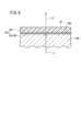
- FIG. 8 is a partially omitted cross-sectional explanatory diagram of a wavelength conversion unit according to a
- a blood vessel visualization system 12 includes a blood vessel visualization device 10A, a camera 14 and an information processing device 16.
- the blood vessel visualization device 10A visualizes the blood vessels 302 (see FIG. 3) of the visualization target region 300 of the living body.
- the visualization target part 300 is a human hand.
- the visualization target part 300 may be a part such as a forearm, an upper arm, a leg, a lower leg, and a thigh of a human body.
- the blood vessel visualization device 10A includes a mounting section 18 and an irradiation section 20.
- the mounting unit 18 is attachable to and detachable from the visualization target region 300 .
- the mounting portion 18 has a shape corresponding to the visualization target region 300 .
- the wearing part 18 has a glove shape surrounding each finger, palm, back and wrist.
- the wearing part 18 is divided into five fingers.
- the tip of the attachment portion 18 in the direction of each fingertip is closed.
- a proximal end portion of the mounting portion 18 opposite to the fingertips is open for inserting and removing the hand in and out of the mounting portion 18 .
- the size and shape of the mounting portion 18 can be set as appropriate.
- the attachment part according to the present invention is formed in a shape surrounding each toe, sole, heel, instep and ankle.
- the attachment portion has a shape divided into five fingers.
- the visualization target region 300 is a forearm, an upper arm, a lower leg, a thigh, or the like
- the mounting portion according to the present invention is formed in a ring shape or a C shape.
- the mounting portion 18 has a mounting base portion 22 and a wavelength converting portion 24.
- the inner surface of the mounting base portion 22 covers the first surface 304 of the visualization target region 300 in the mounted state in which the mounting section 18 is mounted on the visualization target region 300 .
- the inner surface of the wavelength conversion section 24 covers the second surface 306 of the visualization target region 300 opposite to the first surface 304 .
- the inner surface of the wavelength conversion section 24 is in contact (close contact) with the second surface 306 of the visualization target site 300 while the mounting section 18 is mounted.
- the first surface 304 is the palmar side of the hand and the second surface 306 is the dorsal side of the hand.
- the wearing base portion 22 includes a wrist base portion 26, a palm base portion 28, and five finger base portions 30.
- the wrist base portion 26 covers the inner surface of the wrist
- the palm base portion 28 covers the palm
- each finger base portion 30 covers the inner surface of each finger.
- Each finger base part 30 is in contact with (adheres to) the inner surface of each finger in the attached state of the attachment part 18 .
- the wrist base portion 26 is integrally connected to the palm base portion 28 .
- Each finger base portion 30 is integrally connected to the palm base portion 28 so as to protrude from the palm base portion 28 .
- the mounting base portion 22 has flexibility. In this case, the mounting base portion 22 can be easily deformed according to the shape of the visualization target region 300 .
- a soft resin material can be used as a constituent material of the mounting base portion 22 .
- the mounting base portion 22 may be made of a hard resin material. The mounting base portion 22 cannot convert the near-infrared light L1 into the visible light L2.
- the wavelength conversion section 24 includes a wrist covering section 32, a back covering section 34, and five finger covering sections 36.
- the inner surface of the wrist covering portion 32 is in contact (close contact) with the outer surface of the wrist
- the back covering portion 34 is in contact (adhering) with the back of the hand
- each finger covering portion 36 is in contact with the outer surface of each finger.
- the wrist covering portion 32 is integrally connected to the back covering portion 34 .
- Each finger covering part 36 is integrally connected to the back covering part 34 so as to protrude from the back covering part 34 .
- the wavelength conversion section 24 has flexibility. In this case, the wavelength conversion section 24 can be easily deformed according to the shape of the visualization target region 300 .
- the wavelength conversion section 24 includes a wavelength conversion material 38 (optical up-conversion material) that converts the near-infrared light L1 into the visible light L2.
- the wavelength conversion material 38 converts the near-infrared light L1 with a wavelength greater than 700 nm and 2500 nm or less into visible light L2 with a wavelength of 400 nm or more and 700 nm or less.
- Wavelength converting material 38 includes, for example, an inorganic-based optical upconversion emitter or an organic-based optical upconversion emitter.
- Inorganic-based optical upconversion phosphors have, for example, rare earth elements.
- Organic-based optical upconversion emitters include, for example, organometallic complexes or polycyclic aromatic compounds.
- the wavelength converting portion 24 is molded into a predetermined shape from a material including the wavelength converting material 38 .
- the “material containing the wavelength conversion material 38” includes materials consisting only of the wavelength conversion material 38 and mixed materials in which the wavelength conversion material 38 is mixed with other materials.
- the wavelength converting portion 24 is formed into a predetermined shape by using only the wavelength converting material 38, for example.
- the wavelength converting portion 24 may be molded into a predetermined shape from a mixed material.
- the wavelength conversion section 24 is detachably attached to the mounting base section 22 .
- the wavelength converting portion 24 is detachably fixed to the mounting base portion 22 by a retaining portion 40 .
- the fastening part 40 is, for example, a fastener, a button, a hook, or the like.
- the retaining portion 40 detachably locks the outer edge portion of the wavelength converting portion 24 to the outer edge portion of the mounting base portion 22 .
- the clasp 40 locks the outer edge of the wrist cover 32 to the outer edge of the wrist base 26 .
- the fastening portion 40 detachably locks the outer edge portion of the dorsum covering portion 34 to the outer edge portion of the palm base portion 28 .
- the clasp 40 detachably locks the outer edge of each finger cover 36 to the outer edge of each finger base 30 .
- the wavelength conversion section 24 can be replaced with respect to the mounting base section 22 .
- the mounting portion 18 may omit the plurality of finger base portions 30 and the plurality of finger covering portions 36 . In this case, each finger is exposed to the outside from the mounting portion 18 when the mounting portion 18 is mounted.
- the irradiation section 20 has a film section 42, a plurality of light source sections 44, a power supply line 46 and a power supply section 48.
- the film portion 42 is fixed to the inner surface of the palm base portion 28 .
- the film part 42 is a polymer film and has flexibility.
- the thickness of the film portion 42 is, for example, 1 ⁇ m or more and 10 ⁇ m or less. However, the thickness of the film portion 42 can be set appropriately.
- Each light source unit 44 emits near-infrared light L1 having a wavelength greater than 700 nm and 2500 nm or less.
- the light source unit 44 is, for example, an organic light-emitting diode (OLED).
- OLED organic light-emitting diode
- the organic light emitting diode is deposited on the film portion 42 . In this case, since the film portion 42 and the plurality of light source portions 44 can be easily bent, the plurality of light source portions 44 can be efficiently brought into close contact with the first surface 304 of the visualization target region 300 .
- Each light source unit 44 is not limited to an organic light emitting diode, and may be a so-called lamp-type or chip-type light emitting diode.
- the film portion 42 may be adhered to the outer surface of the palm base portion 28 .
- the mounting base portion 22 is made of a material that transmits the near-infrared light L1.
- the number, arrangement, size and shape of the light source units 44 can be changed as appropriate.
- the power supply line 46 supplies power from the power supply section 48 to each light source section 44 .
- a power supply line 46 connects the power supply section 48 and the film section 42 to each other.
- a conductive pattern (not shown) is formed on the film portion 42 to guide the power supplied from the power supply line 46 to each light source portion 44 .
- the power supply line 46 is, for example, a cable embedded inside the mounting base portion 22 . However, the power supply line 46 may be fixed to the inner surface of the mounting base portion 22 .
- the power supply unit 48 is, for example, a primary battery or a secondary battery (battery).
- the power supply section 48 is fixed to the mounting base section 22 . Specifically, the power supply section 48 is fixed to the wrist base section 26 .
- the irradiation unit 20 may be configured to wirelessly supply power from the power supply unit 48 to each light source unit 44 . In this case, the power supply line 46 becomes unnecessary.
- the camera 14 captures a later-described blood vessel image 400 displayed on the wavelength conversion unit 24 .
- the camera 14 transmits the captured image to the information processing device 16 .
- the camera 14 is wired to the information processing device 16 .
- the camera 14 may be wirelessly connected to the information processing device 16 .
- the camera 14 may transmit the captured image to the information processing device 16 via the Internet line.
- the information processing device 16 includes an arithmetic unit 50, a storage unit 52, a display unit 54, and a speaker 56.
- the calculation unit 50 is configured by a processor (processing circuit) such as a CPU (Central Processing Unit), a GPU (Graphics Processing Unit), or the like.
- the calculation unit 50 includes a control unit 58 and an image processing unit 60.
- the calculation unit 50 implements a control unit 58 and an image processing unit 60 by executing programs stored in the storage unit 52 .
- the calculation unit 50 may realize at least part of the control unit 58 and the image processing unit 60 by an integrated circuit. Examples of integrated circuits include ASICs (Application Specific Integrated Circuits) and FPGAs (Field-Programmable Gate Arrays).
- the storage unit 52 includes a volatile memory and a nonvolatile memory.
- Volatile memory includes, for example, RAM (Random Access Memory). This volatile memory is used as a working memory of the processor and temporarily stores data required for processing or calculation. Examples of nonvolatile memory include ROM (Read Only Memory) and flash memory. This non-volatile memory is used as storage memory. Programs, tables, maps, and the like are stored in the nonvolatile memory. At least a portion of memory 52 may be incorporated into a processor or integrated circuit such as those described above.
- the control unit 58 controls the entire information processing device 16 .
- the control unit 58 causes the storage unit 52 to store the image received from the camera 14 .
- the image processing unit 60 analyzes the images stored in the storage unit 52 . Specifically, the image processing unit 60 extracts, for example, changes in images captured before and after a predetermined medical practice.
- the display unit 54 displays images received from the camera 14, images analyzed by the image processing unit 60, and the like.
- a speaker 56 generates an alarm sound or the like.
- the blood vessel visualization system 12 is used, for example, to capture continuous or temporal changes in the same blood vessel 302 in the visualization target region 300 .
- the blood vessel visualization system 12 compares the blood vessel images 400 of the target blood vessel 302 before and after the medical treatment, for example, and compares the effectiveness of the medical treatment (the efficacy of peripheral vasodilators, etc., the effect of exercise therapy, etc.). ) is used when evaluating the blood vessel visualization system 12 .
- the wavelength conversion unit 24 having a color suitable for the visualization target region 300 (the wavelength conversion unit 24 having a color close to the color of the visualization target region 300) is attached to the mounting base unit 22.
- a blood vessel visualization device 10A attached to the is prepared.
- the attachment unit 18 of the blood vessel visualization device 10A is attached to the visualization target region 300 (the left hand in FIG. 1 and the like).
- the mounting base portion 22 and the wavelength conversion portion 24 have flexibility, they are deformed so as to follow the shape of the visualization target region 300 .
- the plurality of light source parts 44 are in close contact with the palm (the first surface 304 of the visualization target part 300).
- the back covering portion 34 is in close contact with the back of the hand (the second surface 306 of the visualization target region 300).
- the wrist covering portion 32 is in close contact with the outer surface of the wrist, each finger base portion 30 is in close contact with the inner surface of each finger, and each finger covering portion 36 is in close contact with the outer surface of each finger. Therefore, the mounting part 18 is fixed to the visualization target part 300 by the frictional resistance between the visualization target part 300 and the mounting part 18 .
- the power supply unit 48 is turned on. Then, as shown in FIG. 3 , near-infrared light L1 is emitted from the plurality of light source units 44 toward the second surface 306 of the visualization target region 300 .
- the near-infrared light L1 passes through portions of the visualization target region 300 other than the blood vessel 302 . In other words, the near-infrared light L1 is absorbed by hemoglobin in the blood inside the blood vessel 302 of the visualization target region 300 .
- the transmitted light that has passed through the visualization target site 300 is converted into visible light L2 by the wavelength conversion material 38 of the wavelength conversion section 24 . Therefore, a visible blood vessel image 400 is displayed on the wavelength conversion unit 24 (see FIG. 2B).
- the blood vessel image 400 displayed on the wavelength conversion unit 24 is captured by the camera 14 .
- Images (still images or moving images) captured by the camera 14 are transmitted to the information processing device 16 and stored in the storage unit 52 .
- the image captured before the medical practice is performed may be referred to as the "first image".
- the first image may not be stored in the storage section 52 of the information processing device 16, but may be stored in a storage section of another computer via the Internet.
- the control unit 58 determines whether the blood vessel image 400 is normal based on the first image, and if it is abnormal (for example, if there is a possibility that blood flow is obstructed by stenosis) An alarm sound is generated from the speaker 56. - ⁇
- the blood vessel image 400 displayed on the wavelength conversion unit 24 is captured by the camera 14 by the same method as described above.
- the image of the blood vessel image 400 after the medical treatment taken by the camera 14 is transmitted to the information processing device 16 and stored in the storage unit 52 .
- an image captured after a medical procedure is performed may be referred to as a "second image".
- the second image may not be stored in the storage unit 52 of the information processing device 16, but may be stored in a storage unit of another computer via the Internet.
- control unit 58 determines whether the blood vessel image 400 is normal based on the second image, and if it is abnormal (for example, if there is a possibility that blood flow is obstructed by stenosis) An alarm sound is generated from the speaker 56. - ⁇
- the image processing unit 60 analyzes the first image and the second image, thereby extracting portions that change between the first image and the second image.
- the control unit 58 causes the display unit 54 to display the analysis result of the image processing unit 60 . This allows users (including patients) to easily and accurately know the effects of medical practice.
- the present embodiment has the following effects.
- the blood vessel visualization device 10A can display a visible blood vessel image 400 on the wavelength conversion unit 24 located above the visualization target region 300 without using a device that converts the near-infrared light L1 into a blood vessel image. Therefore, the blood vessel visualization device 10A can be configured simply and compactly.
- the wavelength conversion unit 24 can be fixed to the visualization target region 300 while being in contact with the second surface 306 of the visualization target region 300, the wavelength of the near-infrared light L1 transmitted through the visualization target region 300 can be efficiently converted. The light can be received by the portion 24 . Therefore, the blood vessel image 400 can be displayed more clearly on the wavelength conversion unit 24 .
- the mounting section 18 has a mounting base section 22 that contacts the first surface 304 when the mounting section 18 is mounted on the visualization target region 300 .
- the wavelength conversion section 24 is detachably attached to the mounting base section 22 .
- the wavelength conversion section 24 when the wavelength conversion section 24 is damaged, only the wavelength conversion section 24 can be replaced. As a result, the cost can be reduced compared to replacing the entire blood vessel visualization device 10A.
- the wavelength conversion unit 24 by preparing a plurality of wavelength conversion units 24 with different colors, it is possible to easily replace the wavelength conversion units 24 with a color suitable for the visualization target site 300 when desired. Specifically, by using the wavelength conversion unit 24 having a color close to the color of the visualization target region 300, the wavelength conversion unit 24 can be made inconspicuous with respect to the visualization target region 300 when worn.
- the light source section 44 is attached to the mounting base section 22 .
- the light source unit 44 is arranged near the visualization target region 300, so that the visualization target region 300 can be efficiently irradiated with the near-infrared light L1 from the light source unit 44.
- the light source section 44 is attached to the inner surface of the mounting base section 22 .
- the light source unit 44 can be brought into contact (close contact) with the first surface 304 of the visualization target region 300, so that the near-infrared light L1 from the light source unit 44 to the visualization target region 300 can be more efficiently applied. can be well illuminated.
- the irradiation unit 20 has a power supply unit 48 that supplies power to the light source unit 44 , and the power supply unit 48 is attached to the mounting unit 18 .
- the blood vessel visualization device 10A becomes more compact and easier to carry than when the irradiation section 20 is provided separately from the mounting section 18.
- the wearing part 18 has a glove shape.
- the mounting portion 18 can be easily mounted manually.
- the blood vessel visualization system 12 includes a camera 14 that captures the blood vessel image 400 displayed on the wavelength conversion unit 24 and an image processing unit 60 that analyzes the image captured by the camera 14 .
- the camera 14 and the image processing unit 60 can acquire changes in the blood vessel image 400 displayed on the wavelength conversion unit 24 after a predetermined period of time has elapsed.
- the blood vessel visualization device 10B includes a mounting section 18 and an irradiation section 61.
- the irradiation unit 61 is provided separately (separated) from the mounting unit 18 .
- the irradiation section 61 has a substrate 62 , a plurality of light source sections 44 , an irradiation support section 64 , a power supply line 46 and a power supply section 48 .
- the substrate 62 has flexibility.
- the multiple light source units 44 are attached to the substrate 62 .
- the light source unit 44 is, for example, a so-called chip-type light emitting diode. However, the light source unit 44 may be a so-called lamp-type light-emitting diode, or may be the above-described organic light-emitting diode.
- the irradiation support section 64 supports the substrate 62 so as to be deformable.
- a power supply line 46 supplies power from a power supply unit 48 to each light source unit 44 .
- the irradiation section 61 is provided separately from the mounting section 18 .
- the blood vessel visualization device 10B can be manufactured easily.
- the blood vessel puncture system 100 includes a blood vessel visualization device 10C and a medical device 200. As shown in FIG. 7, the blood vessel puncture system 100 includes a blood vessel visualization device 10C and a medical device 200. As shown in FIG. 7, the blood vessel puncture system 100 includes a blood vessel visualization device 10C and a medical device 200. As shown in FIG. 7, the blood vessel puncture system 100 includes a blood vessel visualization device 10C and a medical device 200. As shown in FIG.
- the blood vessel visualization device 10C differs from the blood vessel visualization device 10A described above in that a puncture hole 70 for puncturing the blood vessel 302 with the medical device 200 is formed in the wavelength conversion unit 24 . That is, the blood vessel visualization device 10C has the same configuration as the blood vessel visualization device 10A described above except for the puncture hole 70 . Therefore, in the blood vessel visualization device 10C, the same configurations as those of the blood vessel visualization device 10A described above are denoted by the same reference numerals, and descriptions thereof are omitted.
- the puncture hole 70 is positioned so as to include a portion where the blood vessel 302 to be punctured (radial artery, for example) is assumed to be located when the attachment section 18 is attached to the visualization target region 300 .
- the puncture hole 70 is located, for example, in the central portion of the dorsum covering portion 34 .
- the puncture hole 70 is a circular hole.
- the diameter of the puncture hole 70 is set to, for example, 1 mm or more and 10 mm or less.
- the shape, position and size of the puncture hole 70 can be set as appropriate.
- the medical device 200 is, for example, a catheter assembly 201.
- Catheter assembly 201 has needle body 202 , needle hub 204 , catheter shaft 206 and catheter hub 208 .
- Needle body 202 is configured to be able to puncture blood vessel 302 .
- Needle hub 204 is provided at the proximal end of needle body 202 .
- Catheter shaft 206 extends tubularly. In the initial state, the needle body 202 is inserted through the lumen of the catheter shaft 206 .
- a catheter hub 208 is provided at the proximal end of the catheter shaft 206 .
- the medical device 200 is not limited to the catheter assembly 201, and may be a puncture needle or the like for collecting blood.
- the blood vessel visualization device 10C may have a plurality of puncture holes 70.
- the number and positions of puncture holes 70 can be set as appropriate.
- the blood vessel puncture system 100 has the following effects.
- the medical device 200 (catheter assembly 201) can be punctured into the blood vessel 302 while viewing the blood vessel image 400 displayed on the wavelength conversion unit 24. Therefore, the blood vessel puncture by the medical device 200 can be performed. It can be done smoothly.
- the wavelength conversion section 24 has a puncture hole 70 for puncturing the blood vessel 302 with the medical device 200 .
- the blood vessel 302 can be punctured with the medical device 200 through the puncture hole 70 .
- the puncture resistance can be reduced compared to the case where the medical device 200 penetrates the wavelength conversion section 24 .
- part 300 as a foreign material can be reduced.
- the blood vessel puncture system 100 may include the blood vessel visualization device 10A or blood vessel visualization device 10B described above instead of the blood vessel visualization device 10C. Further, the blood vessel puncture system 100 may include the camera 14 and the information processing device 16 described above.
- the blood vessel visualization devices 10A to 10C may include a wavelength conversion section 24a according to the modification shown in FIG. 8 instead of the wavelength conversion section 24 described above.
- the wavelength converting portion 24 a includes a base portion 80 and a coating portion 82 .
- the base portion 80 is made of a material that does not contain the wavelength conversion material 38 .
- the coating portion 82 is formed by coating the inner surface of the base portion 80 (the surface facing the second surface 306 of the visualization target portion 300) with the wavelength conversion material 38 .
- the coating portion 82 may be formed by coating the wavelength conversion material 38 on the outer surface of the base portion 80 (the surface facing in the direction opposite to the visualization target portion 300).
- the coating portion 82 may be provided on both the inner surface and the outer surface of the base portion 80 .
- the wavelength converting portions 24, 24a and the mounting base portion 22 may be integrally molded. That is, the wavelength converters 24 and 24a may be provided integrally with the mounting base section 22 so as not to be detached from the mounting base section 22 . In this case, manufacturing of the blood vessel visualization devices 10A to 10C is facilitated.
Landscapes
- Health & Medical Sciences (AREA)
- Life Sciences & Earth Sciences (AREA)
- General Health & Medical Sciences (AREA)
- Vascular Medicine (AREA)
- Veterinary Medicine (AREA)
- Public Health (AREA)
- Heart & Thoracic Surgery (AREA)
- Biomedical Technology (AREA)
- Animal Behavior & Ethology (AREA)
- Engineering & Computer Science (AREA)
- Hematology (AREA)
- Pathology (AREA)
- Physics & Mathematics (AREA)
- Anesthesiology (AREA)
- Dermatology (AREA)
- Surgery (AREA)
- Medical Informatics (AREA)
- Molecular Biology (AREA)
- Biophysics (AREA)
- Dentistry (AREA)
- Oral & Maxillofacial Surgery (AREA)
- Chemical & Material Sciences (AREA)
- Analytical Chemistry (AREA)
- Biochemistry (AREA)
- General Physics & Mathematics (AREA)
- Immunology (AREA)
- Measurement Of The Respiration, Hearing Ability, Form, And Blood Characteristics Of Living Organisms (AREA)
Priority Applications (2)
| Application Number | Priority Date | Filing Date | Title |
|---|---|---|---|
| JP2023580214A JPWO2023153319A1 (https=) | 2022-02-09 | 2023-02-03 | |
| US18/787,637 US20240382697A1 (en) | 2022-02-09 | 2024-07-29 | Blood vessel visualization device, blood vessel puncture system, and blood vessel visualization system |
Applications Claiming Priority (2)
| Application Number | Priority Date | Filing Date | Title |
|---|---|---|---|
| JP2022018463 | 2022-02-09 | ||
| JP2022-018463 | 2022-02-09 |
Related Child Applications (1)
| Application Number | Title | Priority Date | Filing Date |
|---|---|---|---|
| US18/787,637 Continuation US20240382697A1 (en) | 2022-02-09 | 2024-07-29 | Blood vessel visualization device, blood vessel puncture system, and blood vessel visualization system |
Publications (1)
| Publication Number | Publication Date |
|---|---|
| WO2023153319A1 true WO2023153319A1 (ja) | 2023-08-17 |
Family
ID=87564233
Family Applications (1)
| Application Number | Title | Priority Date | Filing Date |
|---|---|---|---|
| PCT/JP2023/003490 Ceased WO2023153319A1 (ja) | 2022-02-09 | 2023-02-03 | 血管可視化装置、血管穿刺システム及び血管可視化システム |
Country Status (3)
| Country | Link |
|---|---|
| US (1) | US20240382697A1 (https=) |
| JP (1) | JPWO2023153319A1 (https=) |
| WO (1) | WO2023153319A1 (https=) |
Citations (4)
| Publication number | Priority date | Publication date | Assignee | Title |
|---|---|---|---|---|
| JP2004237051A (ja) * | 2003-02-06 | 2004-08-26 | Ogawa Hiroteru | 血管可視化方法ならびに装置 |
| JP2008167792A (ja) * | 2007-01-09 | 2008-07-24 | Hitachi Maxell Ltd | 生体情報取得デバイス |
| JP2015033585A (ja) * | 2012-05-29 | 2015-02-19 | 国立大学法人高知大学 | 動脈可視化方法、動脈可視化装置、および動脈撮像装置 |
| WO2016182075A1 (ja) * | 2015-05-13 | 2016-11-17 | 株式会社プラス・メッド | 動脈可視化装置 |
-
2023
- 2023-02-03 JP JP2023580214A patent/JPWO2023153319A1/ja active Pending
- 2023-02-03 WO PCT/JP2023/003490 patent/WO2023153319A1/ja not_active Ceased
-
2024
- 2024-07-29 US US18/787,637 patent/US20240382697A1/en active Pending
Patent Citations (4)
| Publication number | Priority date | Publication date | Assignee | Title |
|---|---|---|---|---|
| JP2004237051A (ja) * | 2003-02-06 | 2004-08-26 | Ogawa Hiroteru | 血管可視化方法ならびに装置 |
| JP2008167792A (ja) * | 2007-01-09 | 2008-07-24 | Hitachi Maxell Ltd | 生体情報取得デバイス |
| JP2015033585A (ja) * | 2012-05-29 | 2015-02-19 | 国立大学法人高知大学 | 動脈可視化方法、動脈可視化装置、および動脈撮像装置 |
| WO2016182075A1 (ja) * | 2015-05-13 | 2016-11-17 | 株式会社プラス・メッド | 動脈可視化装置 |
Also Published As
| Publication number | Publication date |
|---|---|
| JPWO2023153319A1 (https=) | 2023-08-17 |
| US20240382697A1 (en) | 2024-11-21 |
Similar Documents
| Publication | Publication Date | Title |
|---|---|---|
| JP7795910B2 (ja) | 複数配列を使用する医用撮像方法 | |
| JP6606067B2 (ja) | モジュール型生理学的モニタリング・システム、キット、および方法 | |
| KR101564066B1 (ko) | 상대물에 따라 동작을 달리하는 생체 신호 측정 장치 | |
| CN109791295A (zh) | 使用增强和虚拟现实眼镜的成像修改、显示和可视化 | |
| US9675518B2 (en) | Non-invasive methods for prevention, detection, treatment, and healing of neoplastic processes in humans | |
| US20180360373A1 (en) | Wearable device and method for determining electro-dermal activity of a subject | |
| US20080119700A1 (en) | Hand and Digit Immobilizer for Pulse Oximeter | |
| WO2016003268A2 (en) | Method and device for measuring a health status and physiological parameters of an user at rest and under movement | |
| US20050085736A1 (en) | Portable ECG detector | |
| US20160136045A1 (en) | Guiding means for administering acupuncture and other healing procedures | |
| McAdams et al. | Wearable sensor systems: The challenges | |
| WO2023153319A1 (ja) | 血管可視化装置、血管穿刺システム及び血管可視化システム | |
| TW202000122A (zh) | 靜脈感測裝置 | |
| US11934583B2 (en) | Wearable data communication apparatus, kits, methods, and systems | |
| EP3955845A1 (en) | Light-powered light-emitting tissue marker | |
| JP7426731B2 (ja) | 指先用医療用具 | |
| JP7728200B2 (ja) | 血管可視化部材、血管可視化装置、血管穿刺システム及び血管可視化システム | |
| US12465699B2 (en) | Blood vessel visualization member, blood vessel visualization device, blood vessel puncture system, and blood vessel visualization system | |
| JP6906252B2 (ja) | 医療用具 | |
| KR101967362B1 (ko) | 광전송 카테터 | |
| Sharma | Artificial Intelligence-Machine Learning and Wearable Technology: Transforming Vascular Health Care | |
| US9155591B2 (en) | Treatment limiter | |
| US10413380B2 (en) | Illuminated catheterization device | |
| CN212488627U (zh) | 一种便于操作的上肢介入手术病患用手术服 | |
| US20250166787A1 (en) | Visualization of an internal process of an automated operation |
Legal Events
| Date | Code | Title | Description |
|---|---|---|---|
| 121 | Ep: the epo has been informed by wipo that ep was designated in this application |
Ref document number: 23752784 Country of ref document: EP Kind code of ref document: A1 |
|
| WWE | Wipo information: entry into national phase |
Ref document number: 2023580214 Country of ref document: JP |
|
| NENP | Non-entry into the national phase |
Ref country code: DE |
|
| 122 | Ep: pct application non-entry in european phase |
Ref document number: 23752784 Country of ref document: EP Kind code of ref document: A1 |