WO2023153299A1 - 情報処理システム、及び、情報処理方法 - Google Patents
情報処理システム、及び、情報処理方法 Download PDFInfo
- Publication number
- WO2023153299A1 WO2023153299A1 PCT/JP2023/003340 JP2023003340W WO2023153299A1 WO 2023153299 A1 WO2023153299 A1 WO 2023153299A1 JP 2023003340 W JP2023003340 W JP 2023003340W WO 2023153299 A1 WO2023153299 A1 WO 2023153299A1
- Authority
- WO
- WIPO (PCT)
- Prior art keywords
- tws
- acceleration
- state
- attachment
- information processing
- Prior art date
- Legal status (The legal status is an assumption and is not a legal conclusion. Google has not performed a legal analysis and makes no representation as to the accuracy of the status listed.)
- Ceased
Links
Images




Classifications
-
- H—ELECTRICITY
- H04—ELECTRIC COMMUNICATION TECHNIQUE
- H04W—WIRELESS COMMUNICATION NETWORKS
- H04W4/00—Services specially adapted for wireless communication networks; Facilities therefor
- H04W4/02—Services making use of location information
- H04W4/025—Services making use of location information using location based information parameters
- H04W4/027—Services making use of location information using location based information parameters using movement velocity, acceleration information
-
- H—ELECTRICITY
- H04—ELECTRIC COMMUNICATION TECHNIQUE
- H04R—LOUDSPEAKERS, MICROPHONES, GRAMOPHONE PICK-UPS OR LIKE ACOUSTIC ELECTROMECHANICAL TRANSDUCERS; ELECTRIC HEARING AIDS; PUBLIC ADDRESS SYSTEMS
- H04R1/00—Details of transducers, loudspeakers or microphones
- H04R1/10—Earpieces; Attachments therefor ; Earphones; Monophonic headphones
-
- H—ELECTRICITY
- H04—ELECTRIC COMMUNICATION TECHNIQUE
- H04R—LOUDSPEAKERS, MICROPHONES, GRAMOPHONE PICK-UPS OR LIKE ACOUSTIC ELECTROMECHANICAL TRANSDUCERS; ELECTRIC HEARING AIDS; PUBLIC ADDRESS SYSTEMS
- H04R3/00—Circuits for transducers
Definitions
- the present technology relates to an information processing system and an information processing method, and more particularly to an information processing system and an information processing method that enable determination that cannot be determined using a single data by sharing acceleration data among a plurality of devices. .
- Patent Document 1 discloses that a sensor for detecting attachment/detachment of the wearable device to the user is attached to the attachment portion of the wearable device.
- Acceleration sensors are installed in various devices, and the acceleration data detected by the acceleration sensors is used for various purposes. If acceleration data can be shared among a plurality of devices, it will be possible to make judgments that cannot be made with single data, and the acceleration sensor can be used more effectively in conjunction with other uses.
- This technology has been developed in view of this situation, and it makes it possible to make decisions that cannot be made with a single data by sharing acceleration data between multiple devices.
- An information processing system based on a first acceleration and a second acceleration, which are respective accelerations of a first device and a second device detachably attached to a predetermined portion facing each other,
- the information processing system includes a processing unit that determines whether or not the first device and the second device are in a facing position relationship, and detects attachment/detachment states of the first device and the second device.
- An information processing method is an information processing system having a processing unit.
- a first acceleration and a second Based on the acceleration, it is determined whether or not the first device and the second device are in a facing position relationship, and the attachment/detachment state of the first device and the second device is detected.
- An information processing system is an information processing system including a communication unit that transmits acceleration of a first device via wireless communication to a second device that is connected to the first device via wireless communication. is.
- the acceleration of the first device is transmitted by the wireless communication to the second device that is connected to the first device by wireless communication.
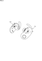
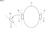
- FIG. 4 is a diagram illustrating appearances of TWS(L) and TWS(R); It is a figure explaining an outline of this art. It is a figure explaining an outline of this art.
- FIG. 10 is a diagram showing an example of processing associated with transitions between attaching/detaching states of TWS(L) and TWS(R) to a user's ear.
- FIG. 4 is a block diagram illustrating attachment/detachment state detection according to the first embodiment; 4 is a flowchart illustrating an example of a procedure for detecting an attachment/detachment state according to the first embodiment; It is a figure explaining the determination processing in a state determination part.
- FIG. 4 is a diagram illustrating appearances of TWS(L) and TWS(R); It is a figure explaining an outline of this art. It is a figure explaining an outline of this art.
- FIG. 10 is a diagram showing an example of processing associated with transitions between attaching/detaching states of TWS(L) and TWS(R
- FIG. 11 is a block diagram illustrating attachment/detachment state detection according to the second embodiment;
- FIG. 11 is a flow chart exemplifying a processing procedure for attachment/detachment state detection according to the second embodiment;
- FIG. 11 is a flow chart exemplifying a processing procedure for attachment/detachment state detection according to the second embodiment;
- FIG. 10 is a flow chart illustrating a procedure for detecting attachment/detachment states of TWS(L) and TWS(R) by always using an auxiliary sensor;
- FIG. 1 is a block diagram showing a configuration example of an information processing system according to an embodiment of the present technology.
- an information processing system 1 which is an embodiment of an information processing system to which the present technology is applied, includes a smartphone 11, TWS (L) (True Wireless Stereo (Left): complete wireless stereo (left side)) 12L, and , TWS(R) (True Wireless Stereo (Right)) 12R.
- any two devices among the smartphone 11, TWS(L) 12L, and TWS(R) 12R can be connected by wireless communication conforming to a predetermined communication standard.
- Bluetooth registered It is assumed that connection is possible by wireless communication conforming to the Bluetooth (registered trademark) Low Energy standard (hereafter referred to as BLE), which is one of the Bluetooth (registered trademark) standards.
- BLE Low Energy standard
- the connection between devices by BLE wireless communication is simply referred to as connection, connection by BLE, or the like.
- the state in which connection by wireless communication is being performed is the state in which the wireless communication of the communication unit is enabled, and the state in which connection by wireless communication is not being performed. is in a state in which the wireless communication of the communication unit is disabled.
- the wireless communication standard that connects devices may be any standard other than BLE, and the wireless communication that connects devices may not all be of the same standard.
- the smartphone 11 is a well-known information processing device. Among the components included in the smartphone 11, there are a processing unit 31 and a communication unit 32 as components related to wireless communication with the TWS(L) 12L and the TWS(R) 12R.
- the processing unit 31 executes a program stored in a storage unit (not shown) and executes processing according to the program.
- the processing unit 31 supplies the communication unit 32 with data (data body) such as audio data to be transmitted to the TWS(L) 12L and the TWS(R) 12R connected to the smartphone 11 .
- the processing unit 31 acquires data transmitted by the TWS(L) 12L and the TWS(R) 12R connected to the smartphone 11 via the communication unit 32 .
- the communication unit 32 performs processes such as encapsulation and modulation on the data supplied from the processing unit 31. As a result, the communication unit 32 generates BLE-compliant transmission data (a packet of a predetermined bit length) and transmits it as radio waves to the TWS(L) 12L and TWS(R) 12R. The communication unit 32 receives transmission data transmitted as radio waves from the TWS(L) 12L and TWS(R) 12R connected to the smartphone 11 . The communication unit 32 performs processing such as demodulation and decapsulation on the received transmission data, and supplies the data to the processing unit 31 .
- BLE-compliant transmission data a packet of a predetermined bit length
- the communication unit 32 receives transmission data transmitted as radio waves from the TWS(L) 12L and TWS(R) 12R connected to the smartphone 11 .
- the communication unit 32 performs processing such as demodulation and decapsulation on the received transmission data, and supplies the data to the processing unit 31 .
- the smartphone 11 is an example, and may be any device such as a personal computer, a music player, or a mobile terminal.
- TWS(L)12L and TWS(R)12R represent audio output devices such as earphones that support complete wireless stereo.
- FIG. 2 exemplifies the appearance of TWS(L) 12L and TWS(R) 12R, which are earphones. It is used in combination with an earphone for left side) and an earphone for right (for right side) worn on the right ear.
- the TWS(L) 12L and TWS(R) 12R are denoted by TWS(L) and TWS(R) without any reference numerals.
- TWS(L) 12L and TWS(R) 12R are examples, and the present technology is applied to two devices that are detachably attached to a predetermined portion such as the head (especially ears) facing each other. obtain.
- TWS(L) has an acceleration sensor 51L, an auxiliary sensor 52L, a processing section 53L, and a communication section 54L.
- the acceleration sensor 51L detects acceleration in orthogonal three-axis directions.
- a detection signal (acceleration data) of the acceleration sensor 51L is supplied to the processing section 53L.
- the auxiliary sensor 52L detects contact with the ear.
- the auxiliary sensor 52L is not limited to a specific type as long as it is a proximity sensor, contact sensor, pulse wave sensor, or other sensor that detects the proximity or contact of an object.
- a detection signal of the auxiliary sensor 52L is supplied to the processing section 53L.
- the processing unit 53L executes a program stored in a storage unit (not shown) and executes processing according to the program.
- the processing unit 53L supplies data (data body) to be transmitted to the smart phone 11 and TWS(R) connected to the TWS(L) 12 to the communication unit 54L.
- the processing unit 53L acquires data transmitted by the smartphone 11 or TWS(R) connected to the TWS(L) via the communication unit 54L.
- the processing unit 53L also detects the attachment/detachment state of TWS(L) and TWS(R).
- the processing unit 53L exemplifies a functional configuration related to detection of the attachment/detachment state.
- the processing unit 53L has a sensor value acquisition unit 71L, a state determination unit 72L, and a state storage unit 73R.
- the sensor value acquisition unit 71L acquires sensor values (acceleration data) detected by the acceleration sensor 51L. Further, the sensor value acquisition unit 71L acquires the sensor value (acceleration data) detected by the TWS(R) acceleration sensor 51R through the communication unit 54L.
- the state determination unit 72L determines the attachment/detachment state of TWS(L) and TWS(R) based on the sensor value acquired by the sensor value acquisition unit 71 or the information stored in the state storage unit 73L.
- the state storage unit 73L stores the current attachment/detachment state of TWS(L) determined by the state determination unit 72L.
- the state storage unit 73L may store attachment/detachment states of TWS(L) and TWS(R).
- the communication unit 54L performs processes such as encapsulation and modulation on the data supplied from the processing unit 53L. As a result, the communication unit 54L generates BLE-compliant transmission data (a packet of a predetermined bit length), and transmits the data as radio waves to the smartphone 11 and TWS(R) connected to TWS(L). The communication unit 54L receives transmission data (packets) transmitted as radio waves from the smartphone 11 and TWS(R) connected to TWS(L). The communication unit 54L performs processing such as demodulation and decapsulation on the received transmission data, and supplies the processed data to the processing unit 53L.
- BLE-compliant transmission data a packet of a predetermined bit length
- the communication unit 54L receives transmission data (packets) transmitted as radio waves from the smartphone 11 and TWS(R) connected to TWS(L).
- the communication unit 54L performs processing such as demodulation and decapsulation on the received transmission data, and supplies the processed data to the processing unit 53L.
- the TWS(R) has an acceleration sensor 51R, an auxiliary sensor 52R, a processing section 53R, and a communication section 54R.
- the acceleration sensor 51R, the auxiliary sensor 52R, the processing unit 53R, and the communication unit 54R correspond to the acceleration sensor 51L, the auxiliary sensor 52L, the processing unit 53L, and the communication unit 54L of TWS(L), respectively. , so that the description is omitted.
- a system means a set of multiple components (devices, modules (parts), etc.), and it does not matter whether all the components are in the same housing. Therefore, a plurality of devices housed in separate housings and connected via a network, and a single device housing a plurality of modules in one housing, are both systems. .
- TWS(L) and TWS(R) are connected to the smartphone 11 by BLE and perform data communication according to GATT (Generic Attribute Profile) specifications, for example, there are the following connection modes.
- the smartphone 11 is the master (parent device), and one of TWS(L) and TWS(R) (for example, TWS(L)) is the slave (child device) of the smartphone. 11.
- the TWS(L) connected to the smartphone 11 as a slave simultaneously becomes a master for the other TWS(R), and the TWS(L) and TWS(R) are connected as the TWS(R) becomes a slave. .
- TWS(L) when stereo audio data is transmitted from the smartphone 11 to TWS(L), for example, TWS(L) separates the stereo audio data into left audio data and right audio data. TWS(L) reproduces left audio data. TWS(L) transmits the separated right audio data to TWS(R), and TWS(R) reproduces the right audio data.
- the smartphone 11 is used as a master, and TWS(L) and TWS(R) are individually connected to the smartphone 11 as slaves.
- the smartphone 11 has a function to transmit the left audio data and the right audio data separately, the left audio data is transmitted from the smartphone 11 to TWS(L). ) reproduces the audio data for the left.
- Right audio data is transmitted from the smartphone 11 to TWS(R), and TWS(R) reproduces the right audio data. Only one of TWS(L) and TWS(R) may be connected to the smartphone 11 to reproduce audio data.
- TWS(L) and TWS(R) connect to the smartphone 11 by BLE and perform broadcast communication
- the smartphone 11 is set as a slave (broadcaster), and TWS(L) and TWS(R) are set as masters ( It is individually connected to the smartphone 11 as an observer).
- the same audio data is transmitted from the smartphone 11 to TWS(L) and TWS(R), and each of TWS(L) and TWS(R) reproduces the audio data.
- TWS(L) and TWS(R) are wireless and have built-in rechargeable batteries. Therefore, low power consumption is important.
- TWS (L) and TWS (R) there are two states of wearing TWS (L) and TWS (R), both of which are attached to the ears, and one of which is attached to the ears.
- the TWS(L) or TWS(R) that are not worn on the ear are not used for listening to audio data.
- both TWS(L) and TWS(R) are not used for listening to audio data.
- BLE connection pairing
- TWS that is not worn on the ear among TWS(L) and TWS(R). Therefore, by not supplying audio data, wasteful power consumption can be reduced.
- TWS that are not attached to the ear it is possible not only not to connect by BLE (disable wireless communication) but also to turn off the power.
- BLE disable wireless communication
- every time the attachment/detachment state of TWS(L) and TWS(R) changes it is not possible to change the connection state of TWS(L) and TWS(R) by BLE or change the playback state of audio data. It takes time and effort for the user to operate.
- Patent Document 1 Japanese Patent Application Laid-Open No. 2020-31444 proposes that a sensor for detecting attachment/detachment of a wearable device to a user is attached to the attachment portion, but does not disclose a specific method. It is also conceivable to detect contact with TWS(L) and TWS(R) with a sensor to detect the attachment/detachment state. However, TWS(L) and TWS(R) may be in contact with parts other than the ears, and malfunctions are likely to occur.
- an acceleration sensor is used to detect the attachment/detachment state of TWS(L) and TWS(R).
- the acceleration sensor can also be used for other purposes (detection of user operations, etc.) besides detecting the attachment/detachment state. It is effective to be able to detect the attachment/detachment state of the . That is, in the present technology, by using both acceleration data detected by the respective acceleration sensors of TWS(L) and TWS(R), TWS(L) and TWS(R), which cannot be determined based on only one data, can be detected. To make it possible to determine the attaching/detaching state of an acceleration sensor and to effectively use an acceleration sensor together with other uses.
- the acceleration sensors 51L and 51R of TWS(L) and TWS(R) in FIG. 1 are triaxial acceleration sensors, and detect acceleration in the three directions of the X, Y, and Z axes set to themselves.
- the acceleration sensors 51L and 51R assume a standard posture (relative posture) when both TWS(L) and TWS(R) are attached to both ears of the user. and 51R are fixed inside TWS(L) and TWS(R) so that their respective X-axes, Y-axes, and Z-axes are parallel to each other.
- FIG. 2 illustrates the directions of the X, Y, and Z axes of acceleration sensors 51L and 51R of TWS(L) and TWS(R), respectively.
- the TWS(L) and TWS(R) are positioned opposite each other (and the posture ).
- the magnitudes of gravity (gravitational acceleration) with respect to each of the three directions of the X, Y, and Z axes detected by the acceleration sensors 51L and 51R are substantially the same.
- a vector indicating the magnitude and direction of gravitational acceleration is called a gravitational vector
- the magnitude and direction of the gravitational vector ( X, Y, Z component values of the gravity vector) almost match.
- FIG. 3 shows how TWS(L) and TWS(R) are worn on both ears and worn on one ear.
- TWS(L) and TWS(R) are positioned opposite each other. Assume that they are arranged in a relationship of Gravity is downward against the user's 101 head.
- the acceleration sensors 51L and 51R are TWS(L) and TWS(R) so that the magnitudes and directions of the gravitational vectors (X, Y, Z components of the gravitational vectors) detected by the acceleration sensors 51L and 51R match. ). Therefore, the magnitude and direction of the gravitational vectors detected by the acceleration sensors 51L and 51R are substantially the same.
- TWS(R) when TWS(R) is removed from the state of wearing both ears, the direction of gravity is downward, but the direction of the gravity vector detected by TWS(R) changes, and the direction of the gravity vector detected by TWS(L) changes. differ from If the user 101 tilts his or her head while wearing both ears as shown in FIG. maintained as is.
- the acceleration sensors 51L and 51R for TWS(L) and TWS(R) use gravity to detect whether or not TWS(L) and TWS(R) are opposed to each other. It is detected whether or not the ear is worn. However, if TWS(L) and TWS(R) are not in a relationship of opposing positions, it is not possible to distinguish between the non-wearing state and the one-ear wearing state.
- the change in the acceleration of TWS(L) and TWS(R) generated in the wearing/wearing state and the output values of the auxiliary sensors 52L and 52R are appropriately used to determine whether the earbud is in the non-wearing state or the one-ear wearing state.
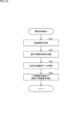
- FIG. 5 is a diagram showing an example of processing associated with transitions between attachment/detachment states of TWS(L) and TWS(R) to the user's ears.
- FIG. 5 there are shown three attachment/detachment states of the TWS(L) and TWS(R), ie, the binaural attachment state, the single ear attachment state, and the non-attachment state.
- BLE connection pairing between the smartphone 11 and TWS(L) and TWS(R) is performed, and TWS(L) and TWS(R) are connected.
- Processing for starting and stopping audio reproduction is processing by an audio reproduction application executed in the processing unit 31 of the smartphone 11 .
- connection is performed between the smartphone 11 and the TWS(L) or TWS(R) worn on the ear, and the TWS(R) worn on the ear L) or start playing audio (music, etc.) from TWS(R).
- TWS(L) and TWS(R) TWS worn on the ear
- TWS(-X) TWS not worn on the ear
- connection is performed between the smartphone 11 and TSW(X) to be worn on the ears, and audio is reproduced from TWS(X). to start.
- TWS(L) and TWS(R) are attached to or detached from the ear. . Unlike the change in acceleration when walking, attaching and detaching the TWS(L) or TWS(R) to the ear generates a large acceleration in one direction. can.
- TWS(L) and TWS(R) attachment/detachment state detection is divided into the first form performed by the TWS that is attached/detached among TWS(L) and TWS(R), and the second form performed by the TWS that is not attached/detached. I will explain separately.
- TWS(L) and TWS(R) performs attachment/detachment state detection of TWS(L) and TWS(R)
- any form other than the first form and the second form may be used.
- Attachment/detachment state detection can be performed in any form by applying the form and the second form.
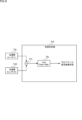
- FIG. 6 is a diagram extracting and showing blocks used for attachment/detachment state detection according to the first embodiment in the information processing system 1 of FIG. However, since the configuration of TWS(R) is the same as that of TWS(L), it is omitted.
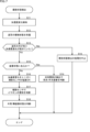
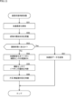
- FIG. 7 is a flowchart illustrating an example of a procedure for detecting the attachment/detachment state according to the first embodiment.
- FIG. 8 is a diagram for explaining determination processing in the state determination section 72L (72R).
- the attachment/detachment state detection according to the first form is performed in the TWS that is attached/detached.
- TWS(L) is operated for attachment/detachment, and attention is paid to attachment/detachment state detection performed by TWS(L).
- TWS(R) performs attachment/detachment state detection processing performed by TWS(L)
- the explanation is omitted. do.
- the sensor value acquisition unit 71L of TWS(L) inquires of the acceleration sensor 51L about the sensor value (acceleration data), and acquires the sensor value from the acceleration sensor 51L at a predetermined cycle. to start. The acquired sensor value is notified to the state determination unit 72L. Based on the sensor value from the sensor value acquisition unit 71L, the state determination unit 72L detects a change in acceleration indicating that the TWS(L) has been attached or detached (hereinafter simply referred to as a change in acceleration) (step S11), it is determined that the attachment/detachment state of TWS(L) is an attachment/detachment operation state in which an attachment/detachment operation is being performed.
- a change in acceleration indicating that the TWS(L) has been attached or detached
- the state determination unit 72L grasps the attachment/detachment state of the TWS(R) (step S12 in FIG. 7).
- the attachment/detachment state of TWS(R) is grasped by the state determination unit 72L of TWS(L) by, for example, the following method. Note that the communication units 54L and 54R are omitted from the block diagram of FIG. are omitted unless necessary.
- the sensor value acquisition unit 71L transmits the sensor value (acceleration data).
- the sensor value acquiring unit 71R acquires sensor values from the acceleration sensor 51R at predetermined intervals in response to inquiries about sensor values, and returns the acquired sensor values to the sensor value acquiring unit 71L.
- the state determination unit 72L acquires the sensor value returned from the sensor value acquisition unit 71R via the sensor value acquisition unit 71L, and grasps the attachment/detachment state of the TWS(R) based on the acquired sensor value.
- the state determination unit 72L determines that the TWS(R) is worn on the right ear. It is determined (deemed) that the device is in a non-wearing state.
- the state determination unit 72L determines TWS. It is determined that (R) is in the attachment/detachment operation state in which attachment/detachment operation is being performed.
- the state determination unit 72L determines TWS ( R), it is determined whether the TWS(R) is attached to the right ear or not attached to the right ear based on the attached/detached state information.
- the state determination unit 72L causes the sensor value acquisition unit 71L to inquire of the sensor value acquisition unit 71R about the attachment/detachment state of TWS(R).
- the attachment/detachment state information stored in the state storage section 73R is acquired via the sensor value acquisition section 71R and the sensor value acquisition section 71L.
- the state determination unit 72L acquires the attachment/detachment state information of the state storage unit 73R.
- TWS(R) may determine (grasp) any one of the wearing state, the non-wearing state, and the attachment/detachment operation state.
- the state determination unit 72L stores the information about the attachment/detachment state of the TWS(R) acquired by inquiring the state storage unit 73L. Based on this, it may be possible to grasp whether the TWS(R) is in the wearing state or the non-wearing state.
- TWS(R) grasps the attachment/detachment state of TWS(R)
- TWS(R) is in the attachment/detachment operation state, whether or not the acceleration change of TWS(R) occurred before TWS(L). That is, it is determined whether or not TWS(R) has entered the attachment/detachment operation state before TWS(L) (step S13 in FIG. 7).
- Whether or not the acceleration change of TWS(R) occurred before TWS(L) is determined by the inquiry of the sensor value or attachment/detachment state to TWS(L) by the sensor value acquisition unit 71R of TWS(R). It can be determined by whether or not it was performed before L).
- the attachment/detachment state detection process is stopped (step S14 in FIG. 7). That is, when acceleration change (attachment/detachment operation) occurs in both TWS(L) and TWS(R), one of them that undergoes the acceleration change first performs attachment/detachment state detection processing, and the other performs attachment/detachment state detection processing. Only the sensor value is returned to one side without performing the processing of . It should be noted that the TWS in which the change in acceleration occurs later may perform the attachment/detachment state detection processing.
- TWS(R ) is the mounted state (step S15 in FIG. 7). Note that the state determination unit 72L continues to periodically acquire the sensor values of the acceleration sensors 51L and 51R, and after the change in acceleration indicating that the TWS(L) is being attached/detached is no longer detected, The determination of step S15 in FIG. 7 is performed.
- the state determination unit 72L determines the TWS(L) based on the relationship between the opposing positions of the TWS(L) and the TWS(R). Therefore, the auxiliary sensor 52L is turned on and the value returned from the auxiliary sensor 52L is obtained (step S16 in FIG. 7). The state determination unit 72L determines whether TWS(L) is in the worn state based on the value acquired from the auxiliary sensor 52L (step S17 in FIG. 7).
- the state determination unit 72L determines that TWS(L) is in the worn state. When it is detected that there is no object approaching or contacting TWS(L), the state determination unit 72L determines that TWS(L) is in the non-wearing state.
- the state determination unit 72L determines that TWS(L) is in the wearing state, TWS(L) and TWS(R) is determined to be worn on one ear (only TWS(L) worn).
- the state determination unit 72L determines that the attachment/detachment state of TWS(L) and TWS(R) is the non-wearing state (step S18 in FIG. 7). After determining the attachment/detachment state, the state determination unit 72L turns off the auxiliary sensor 52L, and stores the attachment/detachment state, which is the determination result, in the state storage unit 73L. In addition, the state determination unit 72L transmits the attachment/detachment state, which is the determination result, to the processing unit 53R of TWS(R), and stores it in the state storage unit 72R.
- the state determination unit 72L detects the change in acceleration indicating that the attachment/detachment operation of the TWS(R) is being performed. Determine the attachment/detachment state. At this time, if TWS(L) is in the attached state, the state determination unit 72L detects the attachment/detachment state of TWS(L) based on the positional relationship between TWS(L) and TWS(R). do. When TWS(L) is in the non-mounted state, the state determination section 72L detects the detachable state of TWS(L) based on the value acquired from the auxiliary sensor 52R.
- the state determination unit 72L causes the state storage unit 73L to store the attachment/detachment state, which is the determination result. In addition, the state determination unit 72L transmits the attachment/detachment state, which is the determination result, to the processing unit 53R of TWS(R), and stores it in the state storage unit 72R.
- the result of the state determination unit 72L determining whether or not the TWS(R) is in the wearing state (step S15 in FIG. 7). If it is determined that TWS(R) is in the attached state, the attachment/detachment state of TWS(L) is detected based on the relationship between the opposing positions of TWS(L) and TWS(R) (step S19). That is, the state determination unit 72L determines whether or not TWS(L) and TWS(R) are in a facing relationship based on the sensor value of the acceleration sensor 51L and the sensor value of the acceleration sensor 51R. . Specifically, as shown in FIG.
- the state determination unit 72L subtracts the sensor value of the acceleration sensor 51L and the sensor value of the acceleration sensor 51R for each of the X, Y, and Z components using the subtractor 91L, A low-pass filter 92L extracts only low-frequency components. That is, the state determination unit 72L extracts the low-frequency component of the difference vector representing the difference from the gravitational vectors detected by the acceleration sensors 51L and 51R. If the difference vector is equal to or less than a predetermined threshold value, the state determination unit 72L regards the difference vector as zero, determines that TWS(L) and TWS(R) are in a facing relationship, and determines that TWS( L) and TWS(R) are determined to be worn on both ears.
- the state determination unit 72L determines that TWS(L) is in the non-wearing state, and determines the attachment/detachment state of TWS(L) and TWS(R) as the one-ear wearing state (TWS(R ) is determined to be the wearing state). After determining the attachment/detachment state, the state determination unit 72L stores the attachment/detachment state, which is the determination result, in the state storage unit 73L. In addition, the state determination unit 72L transmits the attachment/detachment state, which is the determination result, to the processing unit 53R of TWS(R), and stores it in the state storage unit 72R.
- the TWS(L) and TWS(R) are in the non-wearing state, the one-ear wearing state, or the both-ear wearing state. It is possible to detect the attachment/detachment state after the transition from the state of no wearing, the state of wearing one ear, or the state of wearing both ears. It should be noted that both TWS(L) and TWS(R) may perform attachment/detachment state detection when both TWS(L) and TWS(R) are attached/detached.
- the wireless communication status or power supply status of TWS(L) and TWS(R) can be automatically switched between enabled/disabled or on/off according to the wearing status of each, saving the user time and effort. Therefore, the power consumption can be reduced.
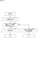
- FIG. 9 is a diagram extracting and showing blocks used for attachment/detachment state detection according to the second embodiment in the information processing system 1 of FIG. 10 and 11 are flowcharts illustrating a procedure for detecting the attachment/detachment state according to the second embodiment.
- the TWS that is not attached/detached performs the attachment/detachment state detection processing according to the procedure of FIG. .
- the TWS that is not attached or detached is in the non-wearing state and may be turned off.
- the TWS subjected to the attachment/detachment operation performs attachment/detachment state detection processing according to the procedure of FIG.
- TWS(L) and TWS(R) are detached and detached
- the TWS that has been detached and detached earlier or later is used for detaching and detaching according to the procedure of FIG. process.
- this description will focus on attachment/detachment state detection performed by TWS(L).
- the attachment/detachment state detection performed by TWS(R) is different only in that the attachment/detachment state detection performed by TWS(L) is performed by TWS(R), so a description thereof will be omitted.
- the sensor value acquisition unit 71L of TWS(L) inquires of the acceleration sensor 51L about the sensor value (acceleration data), and starts acquiring the sensor value from the acceleration sensor 51L at predetermined intervals. The acquired sensor value is notified to the state determination unit 72L. Based on the sensor value of the acceleration sensor 51L, the state determination unit 72L starts detecting a change in acceleration indicating that the TWS(R) has been attached or detached (hereinafter simply referred to as a change in acceleration) (step S31 in FIG. 10). .
- the sensor value acquisition unit 71L acquires the sensor value of the acceleration sensor 51L.
- the state determination unit 72L grasps the attachment/detachment state of the TWS(R) (step S32 in FIG. 10).
- the attachment/detachment state of the TWS(R) is grasped by the same method as the attachment/detachment state detection according to the first embodiment (see step S12 in FIG. 7).
- the state determination unit 72L detects that the TWS(R) is in the attachment/detachment operation state.
- the sensor value of the acceleration sensor 51R is inquired of the acquisition unit 71R, and the sensor value returned at a predetermined cycle from the sensor value acquisition unit 71R is acquired (step S33 in FIG. 10).
- the sensor value acquisition unit 71R inquires about the sensor value (acceleration data) of the acceleration sensor 51R, acquires the sensor value from the acceleration sensor 51R at predetermined intervals, and returns the acquired sensor value to the sensor value acquisition unit 71L.
- the sensor value of the acceleration sensor 51R returned to the sensor value acquisition unit 71L is notified to the state determination unit 72L. Note that the sensor value of the acceleration sensor 51L for TWS(L) is notified from the sensor value acquisition unit 71L to the state determination unit 72L regardless of whether or not the TWS(R) is attached or detached.
- State determination unit 72L determines whether or not TWS(L) and TWS(R) are opposed to each other based on the sensor value of acceleration sensor 51L and the sensor value of acceleration sensor 51R (Fig. 10 step S34). Since the specific processing is the same as the processing described with reference to FIG. 8, the description is omitted. Note that the state determination unit 72L performs the determination of step S34 in FIG. 10 after the change in acceleration indicating that the attachment/detachment operation is being performed for both TWS(L) and TWS(R) is no longer detected.
- the state determination unit 72L determines that the attachment/detachment state of TWS(L) and TWS(R) is the state of being worn on both ears. judge.
- the state determination unit 72L sets the attachment/detachment state of the TWS(L) and the TWS(R) to the one-ear wearing state (only the TWS(L) is wearing state). Determine that there is.
- the state determination unit 72L stores the attachment/detachment state, which is the determination result, in the state storage unit 73L.
- the attachment/detachment state stored in the state storage unit 73L is transmitted to the TWS(R) and stored in the state storage unit 73R of the TWS(R).
- the sensor value acquisition unit 71L of TWS(L) inquires of the acceleration sensor 51L about the sensor value (acceleration data), and starts acquiring the sensor value from the acceleration sensor 51L at predetermined intervals. The acquired sensor value is notified to the state determination unit 72L. Based on the sensor value of the acceleration sensor 51L, the state determination unit 72L starts detecting a change in acceleration indicating that the TWS(L) has been attached/detached (step S51 in FIG. 11).
- the sensor value acquisition unit 71L inquires the sensor value acquisition unit 71R about the sensor value or the attachment/detachment state. R) is grasped (step S52 in FIG. 11).
- the attachment/detachment state of the TWS(R) is grasped by the same method as the attachment/detachment state detection according to the first embodiment (see step S12 in FIG. 7).
- the state determination unit 72L determines whether or not the grasped TWS(R) is in the attachment/detachment state, wearing state, or attachment/detachment operation state (step S53 in FIG. 11). When both TWS(R) and TWS(L) are attached/detached, the state determination unit 72L determines whether the TWS that was attached/detached earlier or later is shown in FIG. Step S53 and subsequent steps are performed. Here, it is assumed that TWS(L) performs the processing after step S53 in FIG. Further, the determination of step S53 in FIG. 11 is performed after the change in acceleration indicating that the TWS(L) is being attached/detached is no longer detected.
- the state determination unit 72L When it is determined that the TWS(R) is in the non-wearing state or the attachment/detachment operation state, the state determination unit 72L, similarly to steps S16 to S18 in FIG. It is determined whether (L) is in the mounted state (steps S54 to S56 in FIG. 11). When determining that TWS(L) is in the wearing state, the state determination unit 72L determines that the attachment/detachment state of TWS(L) and TWS(R) is in the one-ear wearing state (only TWS(L) is in the wearing state). .
- the state determination unit 72L determines that TWS(L) is in the non-wearing state, it determines that the attachment/detachment state of TWS(L) and TWS(R) is the non-wearing state. After determining the attachment/detachment state, the state determination unit 72L turns off the auxiliary sensor 52L, and stores the attachment/detachment state, which is the determination result, in the state storage unit 73L. In addition, the state determination unit 72L transmits the attachment/detachment state, which is the determination result, to the processing unit 53R of TWS(R), and stores it in the state storage unit 72R.
- the state determination unit 72L detects the change in acceleration indicating that the attachment/detachment operation of the TWS(R) is being performed. Determine the attachment/detachment state. At this time, if TWS(L) is in the attached state, the state determination unit 72L detects the attachment/detachment state of TWS(L) based on the positional relationship between TWS(L) and TWS(R). do. When TWS(L) is in the non-mounted state, the state determination section 72L detects the detachable state of TWS(L) based on the value acquired from the auxiliary sensor 52R.
- the state determination unit 72L causes the state storage unit 73L to store the attachment/detachment state, which is the determination result. In addition, the state determination unit 72L transmits the attachment/detachment state, which is the determination result, to the processing unit 53R of TWS(R), and stores it in the state storage unit 72R.
- the state determination unit 72L determines that the grasped attachment/detachment state of TWS(R) is the attached state (step S53 in FIG. 11)
- the sensor value acceleration data
- TWS(R) step S57 in FIG. 11
- the attachment/detachment state detection process of FIG. 10 is performed in TWS(R).
- the TWS(L) and TWS(R) are in the non-wearing state, the one-ear wearing state, or the both-ear wearing state. It is possible to detect the attachment/detachment state after the transition from the state of no wearing, the state of wearing one ear, or the state of wearing both ears.
- the wireless communication status or power supply status of TWS(L) and TWS(R) can be automatically switched between enabled/disabled or on/off according to the wearing status of each, saving the user time and effort. Therefore, the power consumption can be reduced.
- TWS(L) and TWS(R) are based on the sensor values of the acceleration sensors 51L and 51R, and the relationship between the opposing positions of TWS(L) and TWS(R) is determined. Even if it is detected whether or not it is, the attachment/detachment detection may be performed in consideration of the detection results of the auxiliary sensors 52L and 52R to improve the detection accuracy.
- FIG. 12 is a flow chart illustrating the procedure for detecting the attachment/detachment state of TWS(L) and TWS(R) by always using the auxiliary sensor. It should be noted that it is assumed that whether or not TWS(L) and TWS(R) are opposed to each other is already detected. Also, a case where the state determination unit 72L of TWS(L) determines the attachment/detachment state will be described. When the state determination unit 72L of TWS(L) detects a change in acceleration (step S71), it turns on the auxiliary sensor 52L, and grasps the attachment/detachment state of TWS(L) to the ear by the auxiliary sensor 52L.
- the state determination unit 72L determines whether or not attachment/detachment of the auxiliary sensor 52L is confirmed. That is, the state determination unit 72L determines the attachment/detachment state of TWS(L) and TWS(R) ascertained based on the sensor values of the acceleration sensors 51L and 51R and the attachment/detachment state of TWS(L) ascertained by the auxiliary sensor 52L. Determine whether or not they match.
- the state determination unit 72L acquires the information of the auxiliary sensor 52R from TWS(R), and the attachment/detachment state of TWS(R) is also determined based on the sensor values of the acceleration sensors 51L and 51R. It may be determined whether or not it matches the attachment/detachment state of (R).
- step S73 determines the attachment/detachment state of TWS(L) and TWS(R) (step S73). If the state determination unit 72L determines that they do not match, it determines the final attachment/detachment state of TWS(L) and TWS(R) based on information from the auxiliary sensor (step S74).
- the sensor values (acceleration data) detected by the acceleration sensors 51L and 51R at TWS(L) and TWS(R) are appropriately to TWS(R) or from TWS(R) to TWS(L) by BLE.
- Communication between TWS(L) and TWS(R) is not limited to BLE, and may be any wireless or wired communication standard other than BLE.
- the acceleration data may be included in the advertising packet.
- the advertising packet is data transmitted using an advertising channel in advertising performed before the TWS on the slave side establishes a connection (pairing) with the TWS on the master side.
- acceleration is defined as a characteristic of GATT, and the acceleration sensor 51L or 51R
- the detected acceleration data may be transmitted as a GATT characteristic.
- the attachment/detachment state detection processing for TWS(L) and TWS(R) was performed by either the TWS(L) or TWS(R) processing unit. ) may be performed by acquiring necessary information in a processing unit of a device other than TWS(L) and TWS(R).
- the present technology can also take the following configurations. (1) Based on a first acceleration and a second acceleration, which are respective accelerations of a first device and a second device that are detachably attached to a predetermined portion so as to face each other, the positional relationship between the first device and the second device is determined. an information processing system that detects whether or not the first device and the second device are attached or detached. (2) The processing unit detects a direction of gravity with respect to the first device and the second device based on the first acceleration and the second acceleration, and detects the direction of gravity with respect to the first device and the second device based on the direction of gravity.
- the information processing system according to (1) above, wherein it is determined whether or not there is a relationship of opposing positions.
- the first device and the second device are earphones worn on left and right ears, respectively.
- the first device and the second device are complete wireless earphones worn on left and right ears, respectively.
- the first device and the second device each have a first communication unit and a second communication unit that perform wireless communication,
- the first communication unit switches between enabling and disabling the wireless communication according to the attachment/detachment state of the first device,
- the information processing system according to any one of (1) to (5), wherein the second communication unit enables or disables the wireless communication according to the attachment/detachment state of the second device.
- the acceleration information is included in an advertising packet and transmitted when pairing is performed.
- the wireless communication is wireless communication conforming to the Bluetooth (registered trademark) Low Energy standard.
- An information processing system comprising: a communication unit configured to transmit acceleration of a first device by wireless communication to a second device connected to the first device by wireless communication. (13) The information processing system according to (12), wherein the communication unit includes the acceleration in an advertising packet for pairing and transmits it. (14) The information processing system according to (12), wherein the communication unit transmits the acceleration as GATT characteristic information in GATT specification data communication. (15) The information processing system according to any one of (12) to (14), wherein the wireless communication is wireless communication conforming to the Bluetooth (registered trademark) Low Energy standard.
Landscapes
- Engineering & Computer Science (AREA)
- Signal Processing (AREA)
- Computer Networks & Wireless Communication (AREA)
- Physics & Mathematics (AREA)
- Acoustics & Sound (AREA)
- Emergency Alarm Devices (AREA)
- Telephone Function (AREA)
- Headphones And Earphones (AREA)
- Circuit For Audible Band Transducer (AREA)
Abstract
Description
図1は、本技術の実施の形態に係る情報処理システムの構成例を示すブロック図である。
TWS(L)とTWS(R)とがスマートフォン11に対してBLEにより接続し、GATT(Generic Attribute Profile)仕様のデータ通信を行う場合に、例えば、次のような接続形態がある。一の接続形態では、スマートフォン11をマスタ(親機)として、TWS(L)とTWS(R)とのうちのいずれか一方(例えば、TWS(L)とする)がスレーブ(子機)としてスマートフォン11に接続される。スレーブとしてスマートフォン11に接続されたTWS(L)は、同時に他方のTWS(R)に対してマスタとなり、TWS(R)がスレーブとなってTWS(L)とTWS(R)とが接続される。これによれば、スマートフォン11から例えばステレオ音声データがTWS(L)に伝送された場合に、TWS(L)がステレオ音声データを左用の音声データと右用の音声データに分離する。TWS(L)は、左用の音声データを再生する。TWS(L)は、分離した右用の音声データをTWS(R)に伝送し、TWS(R)が、右用の音声データを再生する。
TWS(L)及びTWS(R)は、ワイヤレスであり、充電バッテリが内蔵されている。そのため、低消費電力であることが重要である。TWS(L)及びTWS(R)の耳への着脱状態として、TWS(L)及びTWS(R)のうち、その両方が耳に装着された両耳装着状態と、一方が耳に装着された片耳装着状態と、両方とも耳に装着されていない無装着状態とがある。片耳装着状態では、耳に装着されていないTWS(L)又はTWS(R)は音声データの聴取に使用されていない。無装着状態では、TWS(L)及びTWS(R)の両方が音声データの聴取に使用されていない。したがって、TWS(L)及びTWS(R)の装着状態に応じてTWS(L)及びTWS(R)のうちの耳に装着されていないTWSに対しては、BLEによる接続(ペアリング)を行わず、音声データの供給を行わないことで、無駄な消費電力を低減することができる。耳に装着されていないTWSに対しては、BLEによる接続を行わない(無線通信を無効にする)だけでなく、電源をオフにすることも可能である。しかしながら、TWS(L)及びTWS(R)の着脱状態が変わるごとに、TWS(L)及びTWS(R)のそれぞれのBLEによる接続状態を変更したり、音声データの再生状態を変更することをユーザが操作して行うのは手間を要する。
TWS(L)及びTWS(R)の着脱状態検出は、TWS(L)又はTWS(R)のいずれかに対して耳への着脱操作が行われる際の加速度変化が検出されたときに行われる。TWS(L)又はTWS(R)の耳への着脱操作は歩行時等の加速度変化とは異なり、一方向に向かう大きな加速度が発生するため、加速度変化により着脱操作か否かを判別することができる。
TWS(L)及びTWS(R)の第1形態に係る着脱状態検出について、図6乃至図8を適宜用いて説明する。図6は、図1の情報処理システム1において、第1形態に係る着脱状態検出に使用されるブロックを抽出して示した図である。ただし、TWS(R)の構成はTWS(L)と同様であるので省略している。図7は、第1形態に係る着脱状態検出の処理手順を例示したフローチャートである。図8は、状態判定部72L(72R)における判定処理を説明する図である。
TWS(L)及びTWS(R)の第2形態に係る着脱状態検出について、図9乃至図11を適宜用いて説明する。図9は、図1の情報処理システム1において、第2形態に係る着脱状態検出に使用されるブロックを抽出して示した図である。図10及び図11は、第2形態に係る着脱状態検出の処理手順を例示したフローチャートである。
上記第1形態及び第2形態に係る着脱状態検出において、TWS(L)及びTWS(R)を加速度センサ51L及び51Rのセンサ値に基づいてTWS(L)及びTWS(R)が対向位置の関係であるか否かを検出した場合であっても、補助センサ52L及び52Rの検出結果を考慮して着脱検出を行うようにし、検出精度を高めるようにしてもよい。
記第1形態及び第2形態に係る着脱状態検出において、TWS(L)及びTWS(R)において、加速度センサ51L及び51Rによりそれぞれ検出されたセンサ値(加速度データ)は、適宜、TWS(L)からTWS(R)へ、又は、TWS(R)からTWS(L)へとBLEにより送信される。TWS(L)とTWS(R)との間の通信はBLEに限定されず、BLE以外の任意の無線又は有線通信の規格であってよい。TWS(L)とTWS(R)との間の通信をBLEの規格に準拠した通信等により行う場合、加速度データはアドバタイジング・パケットに含められるようにしてもよい。アドバタイジング・パケットは、スレーブ側のTWSがマスタ側のTWSとの接続(ペアリング)が確立する前に行うアドバタイジングにおいて、アドバタイジング・チャネルを用いて送信するデータである。また、TWS(L)とTWS(R)との間でBLEによる接続が確立した後のGATT仕様のデータ通信を行う場合に、GATTのキャラクタリスティックとして加速度を定義し、加速度センサ51L又は51Rで検出された加速度データをGATTのキャラクタリスティックとして送信する場合であってもよい。
(1)
所定部分に互いに対向して着脱可能に装着される第1装置及び第2装置のそれぞれの加速度である第1加速度及び第2加速度に基づいて、前記第1装置及び第2装置が対向位置の関係か否かを判定して前記第1装置及び第2装置の着脱状態を検出する処理部
を有する情報処理システム。
(2)
前記処理部は、前記第1加速度及び前記第2加速度に基づいて、前記第1装置及び第2装置に対する重力方向を検出し、前記重力方向に基づいて、前記第1装置及び第2装置が前記対向位置の関係か否かを判定する
前記(1)に記載の情報処理システム。
(3)
前記第1装置及び前記第2装置は、音声出力装置を含む
前記(1)又は(2)に記載の情報処理システム。
(4)
前記第1装置及び前記第2装置は、それぞれ左右の耳に装着されるイヤホンである
前記(1)乃至(3)のいずれかに記載の情報処理システム。
(5)
前記第1装置及び前記第2装置は、それぞれ左右の耳に装着される完全ワイヤレスイヤホンである
前記(1)乃至(4)のいずれかに記載の情報処理システム。
(6)
前記第1装置及び第2装置は、それぞれ無線通信を行う通信部である第1通信部及び第2通信部を有し、
前記第1通信部は、前記第1装置の前記着脱状態に応じて前記無線通信を有効または無効に切替え、
前記第2通信部は、前記第2装置の前記着脱状態に応じて前記無線通信を有効または無効に切替える
前記(1)乃至(5)のいずれかに記載の情報処理システム。
(7)
前記処理部は、前記第1加速度及び第2加速度のうちの少なくとも一方の加速度情報を無線通信を通じて取得する
前記(1)乃至(6)のいずれかに記載の情報処理システム。
(8)
前記加速度情報は、ペアリングを行う際のアドバタイジング・パケットに含められて伝送される
前記(7)に記載の情報処理システム。
(9)
前記加速度情報は、GATT仕様のデータ通信において、GATTのキャラクタリスティックの情報として伝送される
前記(7)に記載の情報処理システム。
(10)
前記無線通信は、Bluetooth(登録商標) Low Energy規格に準拠した無線通信である
前記(7)乃至(9)のいずれかに記載の情報処理システム。
(11)
処理部を有する
情報処理システムの
前記処理部が、
所定部分に互いに対向して着脱可能に装着される第1装置及び第2装置のそれぞれの加速度である第1加速度及び第2加速度に基づいて、前記第1装置及び第2装置が対向位置の関係か否かを判定して前記第1装置及び第2装置の着脱状態を検出する
情報処理方法。
(12)
第1装置と無線通信により接続された第2装置に対して、前記第1装置の加速度を前記無線通信により伝送する通信部
を有する情報処理システム。
(13)
前記通信部は、前記加速度を、ペアリングを行う際のアドバタイジング・パケットに含めて伝送する
前記(12)に記載の情報処理システム。
(14)
前記通信部は、前記加速度を、GATT仕様のデータ通信において、GATTのキャラクタリスティックの情報として伝送する
前記(12)に記載の情報処理システム。
(15)
前記無線通信は、Bluetooth(登録商標) Low Energy規格に準拠した無線通信である
前記(12)乃至(14)のいずれかに記載の情報処理システム。
Claims (15)
- 所定部分に互いに対向して着脱可能に装着される第1装置及び第2装置のそれぞれの加速度である第1加速度及び第2加速度に基づいて、前記第1装置及び第2装置が対向位置の関係か否かを判定して前記第1装置及び第2装置の着脱状態を検出する処理部
を有する情報処理システム。 - 前記処理部は、前記第1加速度及び前記第2加速度に基づいて、前記第1装置及び第2装置に対する重力方向を検出し、前記重力方向に基づいて、前記第1装置及び第2装置が前記対向位置の関係か否かを判定する
請求項1に記載の情報処理システム。 - 前記第1装置及び前記第2装置は、音声出力装置を含む
請求項1に記載の情報処理システム。 - 前記第1装置及び前記第2装置は、それぞれ左右の耳に装着されるイヤホンである
請求項1に記載の情報処理システム。 - 前記第1装置及び前記第2装置は、それぞれ左右の耳に装着される完全ワイヤレスイヤホンである
請求項1に記載の情報処理システム。 - 前記第1装置及び第2装置は、それぞれ無線通信を行う通信部である第1通信部及び第2通信部を有し、
前記第1通信部は、前記第1装置の前記着脱状態に応じて前記無線通信を有効または無効に切替え、
前記第2通信部は、前記第2装置の前記着脱状態に応じて前記無線通信を有効または無効に切替える
請求項1に記載の情報処理システム。 - 前記処理部は、前記第1加速度及び第2加速度のうちの少なくとも一方の加速度情報を無線通信を通じて取得する
請求項1に記載の情報処理システム。 - 前記加速度情報は、ペアリングを行う際のアドバタイジング・パケットに含められて伝送される
請求項7に記載の情報処理システム。 - 前記加速度情報は、GATT仕様のデータ通信において、GATTのキャラクタリスティックの情報として伝送される
請求項7に記載の情報処理システム。 - 前記無線通信は、Bluetooth(登録商標) Low Energy規格に準拠した無線通信である
請求項7に記載の情報処理システム。 - 処理部を有する
情報処理システムの
前記処理部が、
所定部分に互いに対向して着脱可能に装着される第1装置及び第2装置のそれぞれの加速度である第1加速度及び第2加速度に基づいて、前記第1装置及び第2装置が対向位置の関係か否かを判定して前記第1装置及び第2装置の着脱状態を検出する
情報処理方法。 - 第1装置と無線通信により接続された第2装置に対して、前記第1装置の加速度を前記無線通信により伝送する通信部
を有する情報処理システム。 - 前記通信部は、前記加速度を、ペアリングを行う際のアドバタイジング・パケットに含めて伝送する
請求項12に記載の情報処理システム。 - 前記通信部は、前記加速度を、GATT仕様のデータ通信において、GATTのキャラクタリスティックの情報として伝送する
請求項12に記載の情報処理システム。 - 前記無線通信は、Bluetooth(登録商標) Low Energy規格に準拠した無線通信である
請求項12に記載の情報処理システム。
Priority Applications (1)
| Application Number | Priority Date | Filing Date | Title |
|---|---|---|---|
| US18/835,552 US20250150784A1 (en) | 2022-02-14 | 2023-02-02 | Information processing system and information processing method |
Applications Claiming Priority (2)
| Application Number | Priority Date | Filing Date | Title |
|---|---|---|---|
| JP2022-020339 | 2022-02-14 | ||
| JP2022020339A JP2023117653A (ja) | 2022-02-14 | 2022-02-14 | 情報処理システム、及び、情報処理方法 |
Publications (1)
| Publication Number | Publication Date |
|---|---|
| WO2023153299A1 true WO2023153299A1 (ja) | 2023-08-17 |
Family
ID=87564341
Family Applications (1)
| Application Number | Title | Priority Date | Filing Date |
|---|---|---|---|
| PCT/JP2023/003340 Ceased WO2023153299A1 (ja) | 2022-02-14 | 2023-02-02 | 情報処理システム、及び、情報処理方法 |
Country Status (3)
| Country | Link |
|---|---|
| US (1) | US20250150784A1 (ja) |
| JP (1) | JP2023117653A (ja) |
| WO (1) | WO2023153299A1 (ja) |
Citations (4)
| Publication number | Priority date | Publication date | Assignee | Title |
|---|---|---|---|---|
| JP2020184692A (ja) * | 2019-05-08 | 2020-11-12 | シャープ株式会社 | 制御システム及びその制御方法 |
| JP2020188392A (ja) * | 2019-05-16 | 2020-11-19 | ローム株式会社 | ステレオイヤホン及び判定装置 |
| WO2021131583A1 (ja) * | 2019-12-25 | 2021-07-01 | ソニーセミコンダクタソリューションズ株式会社 | 同期装置及び同期方法 |
| JP2021153243A (ja) * | 2020-03-24 | 2021-09-30 | 株式会社Jvcケンウッド | 音入出力制御装置、音入出力制御方法、及びプログラム |
-
2022
- 2022-02-14 JP JP2022020339A patent/JP2023117653A/ja active Pending
-
2023
- 2023-02-02 US US18/835,552 patent/US20250150784A1/en active Pending
- 2023-02-02 WO PCT/JP2023/003340 patent/WO2023153299A1/ja not_active Ceased
Patent Citations (4)
| Publication number | Priority date | Publication date | Assignee | Title |
|---|---|---|---|---|
| JP2020184692A (ja) * | 2019-05-08 | 2020-11-12 | シャープ株式会社 | 制御システム及びその制御方法 |
| JP2020188392A (ja) * | 2019-05-16 | 2020-11-19 | ローム株式会社 | ステレオイヤホン及び判定装置 |
| WO2021131583A1 (ja) * | 2019-12-25 | 2021-07-01 | ソニーセミコンダクタソリューションズ株式会社 | 同期装置及び同期方法 |
| JP2021153243A (ja) * | 2020-03-24 | 2021-09-30 | 株式会社Jvcケンウッド | 音入出力制御装置、音入出力制御方法、及びプログラム |
Also Published As
| Publication number | Publication date |
|---|---|
| US20250150784A1 (en) | 2025-05-08 |
| JP2023117653A (ja) | 2023-08-24 |
Similar Documents
| Publication | Publication Date | Title |
|---|---|---|
| US10966012B2 (en) | Wireless earbuds, and a storage and charging capsule therefor | |
| CN206790671U (zh) | 无线耳机组 | |
| CN107809696B (zh) | 一种与耳机盒建立交互的无线耳机 | |
| EP3236639B1 (en) | Portable sound equipment | |
| CN114760554A (zh) | 一种夹耳式耳机的麦克风管理方法、装置及夹耳式耳机 | |
| US20070281762A1 (en) | Signal routing to a communication accessory based on device activation | |
| JP7642752B2 (ja) | モジュール化された眼鏡システム、装置、および方法のためのハードウェア・アーキテクチャ | |
| WO2020107604A1 (zh) | 一种无线播放设备及其播放控制方法和装置 | |
| CN206096664U (zh) | 智能眼镜及其镜腿组件 | |
| JP2013051624A (ja) | 音響再生装置 | |
| JP7830664B2 (ja) | ホール効果センサによる近接の検出及び独立した結合を有するオーディオデバイス | |
| WO2018128577A2 (en) | Wireless earbuds, and a storage and charging capsule therefor | |
| WO2018133323A1 (zh) | 无线耳机装置以及人工智能装置 | |
| CN101263735A (zh) | 用于同步音频数据处理的音频数据处理设备和方法 | |
| TW201543911A (zh) | 多媒體播放系統及其聲道控制方法 | |
| WO2023153299A1 (ja) | 情報処理システム、及び、情報処理方法 | |
| WO2020082391A1 (zh) | 无线耳机的控制方法及相关产品 | |
| JP5760867B2 (ja) | 音響再生装置 | |
| CN208863048U (zh) | 一种无线播放设备及头戴式无线耳机系统 | |
| CN212909978U (zh) | 一种耳机佩戴检测结构和耳挂式耳机 | |
| US9635476B2 (en) | Method of preventing feedback based on detection of posture and devices for performing the method | |
| WO2024222069A1 (zh) | 佩戴位置的识别方法和电子设备 | |
| CN216217534U (zh) | 头戴式立体声音频装置 | |
| CN211509271U (zh) | 一种具有外音自动播放功能的蓝牙耳机套件 | |
| US11863927B2 (en) | Audio device proximity detection |
Legal Events
| Date | Code | Title | Description |
|---|---|---|---|
| 121 | Ep: the epo has been informed by wipo that ep was designated in this application |
Ref document number: 23752764 Country of ref document: EP Kind code of ref document: A1 |
|
| WWE | Wipo information: entry into national phase |
Ref document number: 18835552 Country of ref document: US |
|
| NENP | Non-entry into the national phase |
Ref country code: DE |
|
| 122 | Ep: pct application non-entry in european phase |
Ref document number: 23752764 Country of ref document: EP Kind code of ref document: A1 |
|
| WWP | Wipo information: published in national office |
Ref document number: 18835552 Country of ref document: US |