WO2023152809A1 - 画像処理装置、画像処理方法およびプログラム - Google Patents
画像処理装置、画像処理方法およびプログラム Download PDFInfo
- Publication number
- WO2023152809A1 WO2023152809A1 PCT/JP2022/004976 JP2022004976W WO2023152809A1 WO 2023152809 A1 WO2023152809 A1 WO 2023152809A1 JP 2022004976 W JP2022004976 W JP 2022004976W WO 2023152809 A1 WO2023152809 A1 WO 2023152809A1
- Authority
- WO
- WIPO (PCT)
- Prior art keywords
- image
- size
- clipped
- predetermined
- width direction
- Prior art date
- Legal status (The legal status is an assumption and is not a legal conclusion. Google has not performed a legal analysis and makes no representation as to the accuracy of the status listed.)
- Ceased
Links
Images





Classifications
-
- G—PHYSICS
- G06—COMPUTING OR CALCULATING; COUNTING
- G06T—IMAGE DATA PROCESSING OR GENERATION, IN GENERAL
- G06T3/00—Geometric image transformations in the plane of the image
- G06T3/40—Scaling of whole images or parts thereof, e.g. expanding or contracting
-
- G—PHYSICS
- G06—COMPUTING OR CALCULATING; COUNTING
- G06T—IMAGE DATA PROCESSING OR GENERATION, IN GENERAL
- G06T5/00—Image enhancement or restoration
- G06T5/50—Image enhancement or restoration using two or more images, e.g. averaging or subtraction
-
- G—PHYSICS
- G06—COMPUTING OR CALCULATING; COUNTING
- G06T—IMAGE DATA PROCESSING OR GENERATION, IN GENERAL
- G06T9/00—Image coding
-
- G—PHYSICS
- G06—COMPUTING OR CALCULATING; COUNTING
- G06T—IMAGE DATA PROCESSING OR GENERATION, IN GENERAL
- G06T2207/00—Indexing scheme for image analysis or image enhancement
- G06T2207/20—Special algorithmic details
- G06T2207/20112—Image segmentation details
- G06T2207/20132—Image cropping
-
- G—PHYSICS
- G06—COMPUTING OR CALCULATING; COUNTING
- G06T—IMAGE DATA PROCESSING OR GENERATION, IN GENERAL
- G06T2207/00—Indexing scheme for image analysis or image enhancement
- G06T2207/20—Special algorithmic details
- G06T2207/20212—Image combination
- G06T2207/20221—Image fusion; Image merging
Definitions
- the present disclosure relates to an image processing device, an image processing method, and a program.
- images are generally resized by enlarging or reducing them (see, for example, Non-Patent Document 2).
- the size of the clipped image is normalized to the predetermined size by enlarging the size of the clipped image, and the size of the clipped image is larger than the predetermined size. is also large, the size of the clipped image is normalized to a predetermined size by reducing the size of the clipped image.
- the size of the image to be used (the clipped image) is standardized (standardized). ), it is difficult with existing techniques to standardize the size of the image while maintaining the aspect ratio of the object contained in the image.
- An object of the present disclosure which has been made in view of the above problems, is to standardize the size of a clipped image obtained by clipping a region including a predetermined target to a predetermined size while maintaining the aspect ratio of the target.
- An object of the present invention is to provide an image processing device, an image processing method, and a program that can
- the image processing apparatus includes an image clipping unit that clips an image of a rectangular area including a predetermined target object from an input image as a clipped image, and while maintaining the aspect ratio of the target object, An image size standardization unit that standardizes the size of the clipped image to a predetermined size, and an image output unit that outputs the standardized clipped image.
- an image clipping unit that clips an image of a rectangular area including a predetermined target object from an input image as a clipped image, and while maintaining the aspect ratio of the target object
- An image size standardization unit that standardizes the size of the clipped image to a predetermined size
- an image output unit that outputs the standardized clipped image.
- a predetermined image is added to at least one of the width direction and the height direction of the clipped image. Then, an additional image having the same aspect ratio as the predetermined size is generated, and the additional image is compressed to the predetermined size, thereby standardizing the size of the clipped image to the predetermined size.
- an image processing method is an image processing method by an image processing device, comprising: cutting out an image of a rectangular area including a predetermined object from an input image as a cutout image; standardizing the size of the clipped image to a predetermined size while maintaining the aspect ratio of the object; and outputting the standardized clipped image, both in the width direction and the height direction.
- the size of the clipped image is equal to or smaller than the predetermined size, normalizing the size of the clipped image to the predetermined size by adding a predetermined image in the width direction and the height direction of the clipped image;
- adding a predetermined image to at least one of the width direction and the height direction of the clipped image By generating an additional image having the same aspect ratio as a predetermined size and compressing the additional image to the predetermined size, the size of the clipped image is standardized to the predetermined size.
- a program according to the present disclosure causes a computer to operate as the image processing device described above.
- the size of a clipped image obtained by clipping a region including a predetermined target is standardized to a predetermined size while maintaining the aspect ratio of the target. be able to.
- FIG. 1 is a diagram illustrating a configuration example of an image processing device according to an embodiment of the present disclosure
- FIG. FIG. 2 is a diagram showing a configuration example of an image size normalization unit shown in FIG. 1
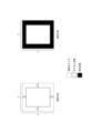
- FIG. 3 is a diagram showing an example of standardization of the size of a clipped image by the image expansion unit shown in FIG. 2
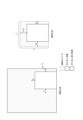
- FIG. 10 is a diagram showing another example of standardization of the cut-out image size by the image expansion unit shown in FIG. 2
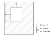
- FIG. 10 is a diagram showing still another example of standardization of the size of a clipped image by the image expansion unit shown in FIG. 2
- 3 is a diagram showing an example of a pattern of extension of a clipped image by the image extension unit shown in FIG. 2
- FIG. 10 is a diagram showing another example of a pattern of expansion of a clipped image by the image expansion unit shown in FIG. 2;
- FIG. 10 is a diagram showing still another example of a pattern of expansion of a clipped image by the image expansion unit shown in FIG. 2;
- FIG. 10 is a diagram showing still another example of extension of the clipped image by the image extension unit shown in FIG. 2;
- 3 is a diagram showing an example of standardization of the size of a clipped image by the image compression unit shown in FIG. 2;
- FIG. 3 is a diagram showing another example of standardization of the size of a clipped image by the image compression unit shown in FIG. 2;
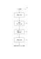
- FIG. 2 is a flow chart showing an example of the operation of the image processing apparatus shown in FIG. 1;
- 2 is a diagram showing an example of the hardware configuration of the image processing apparatus shown in FIG. 1;
- FIG. 1 is a diagram showing a configuration example of an image processing device 10 according to an embodiment of the present disclosure.
- the image processing apparatus 10 according to the present embodiment generates and outputs a clipped image, which is an image obtained by clipping a region including a predetermined target object included in the input image.
- the input image is, for example, an image of an infrastructure facility (such as a utility pole).
- the image processing apparatus 10 outputs an image of an approximate area including the infrastructure equipment as a clipped image from the input image.
- a clipped image generated by the image processing apparatus 10 is used, for example, to detect a predetermined target object (for example, infrastructure equipment) in the image.
- the image processing apparatus 10 includes an image input unit 11, an image clipping unit 12, an image size normalization unit 13, and an image output unit .
- the image input unit 11 receives an image from which a clipped image is generated.
- the input image input to the image input unit 11 is, for example, an image obtained by photographing a predetermined infrastructure facility, as described above.
- the image input section 11 outputs the input image to the image clipping section 12 .
- the image clipping unit 12 clips a rectangular image of an approximate area including a predetermined object from the input image output from the image input unit 11 . That is, the image clipping unit 12 clips an image of a rectangular area including a predetermined object from the input image as a clipped image.
- the image clipping unit 12 clips a clipped image including a predetermined target object from the input image using a detector created in advance by a deep learning method such as Yolo, for example.
- the image size is reduced by removing unnecessary parts for detection, and the calculation at the time of deep learning You can prevent slowdowns.
- the possibility of erroneously detecting an object that is not a detection target is reduced, so detection accuracy can be improved.
- the image clipping unit 12 outputs the clipped image clipped from the input image to the image size normalization unit 13 together with the input image as necessary.
- the image size standardization unit 13 standardizes the size of the clipped image to a predetermined size (standardized size) while maintaining the aspect ratio of the predetermined object included in the clipped image output from the image clipping unit 12. .
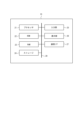
- FIG. 2 is a diagram showing a configuration example of the image size normalization unit 13. As shown in FIG.
- the image size normalization unit 13 includes a determination unit 131, an image extension unit 132, and an image compression unit 133.
- a clipped image is input from the image clipping unit 12 to the determination unit 131 .
- the determination unit 131 determines whether the size of the input clipped image exceeds the standardized size in the width direction and the height direction. For example, the determination unit 131 determines that the number of pixels in the width direction and the number of pixels in the height direction of the clipped image are the number of pixels in the width direction (X (pix)) and the number of pixels in the height direction (Y (pix)) of the standardized size, respectively. It is determined whether or not the
- the determination unit 131 determines that the size of the clipped image is equal to or smaller than the standardized size in both the width direction and the height direction, it outputs the clipped image to the image extension unit 132 . Further, when determining that the size of the clipped image is larger than the normalized size in at least one of the width direction and the height direction, the determination unit 131 outputs the clipped image to the image compression unit 133 .
- the image expansion unit 132 normalizes the size of the cutout image to the standardized size by adding a predetermined image in the width direction and the height direction of the cutout image output from the determination unit 131, and produces the normalized cutout image. is output to the image output unit 14 .
- the details of the standardization of the cut-out image size by the image expansion unit 132 will be described later.
- the image compression unit 133 generates an additional image by adding a predetermined image to at least one of the width direction and the height direction of the clipped image output from the determination unit 131 . Then, the image compression unit 133 compresses the generated additional image to the standardized size to standardize the size of the clipped image to the standardized size, and outputs the standardized clipped image to the image output unit 14 .
- the details of the standardization of the cut-out image size by the image compression unit 133 will be described later.
- the image size normalization unit 13 sets the predetermined size in the width direction and the height direction of the clipped image.
- the image size normalization unit 13 sets a predetermined size in at least one of the width direction and the height direction of the clipped image. An image is appended to produce an appended image with the same aspect ratio as the normalized size. Then, the image size standardization unit 13 standardizes the size of the clipped image to the standardized size by compressing the generated additional image to the standardized size.
- the image output unit 14 outputs an image group consisting of normalized clipped images output from the image size standardization unit 13 (the image expansion unit 132 and the image compression unit 133).
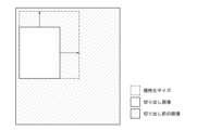
- FIG. 3 is a diagram showing an example of standardization of the cut-out image size by the image expansion unit 132.
- the image extension unit 132 adds predetermined images having a width a to the left and right sides of the cutout image so that the widthwise size of the cutout image becomes the widthwise size X of the standardized size. to expand the cropped image.
- the image extension unit 132 adds predetermined images of height b to the top and bottom of the clipped image so that the size of the clipped image in the height direction becomes the size Y of the standardized size in the height direction, Expand the clipped image. That is, the image extension unit 132 adds a predetermined image symmetrically to both sides of the cutout image in the width direction (same width on both sides of the cutout image in the width direction).
- the image extension unit 132 adds a predetermined image symmetrically to both sides of the clipped image in the height direction (same height on both sides of the clipped image in the height direction).
- the image expansion unit 132 converts an image made up of uniform pixels (in the example of FIG. 3, a black image made up of only black pixels) into a clipped image. Add to both sides in the width direction and both sides in the height direction.
- the aspect ratio of the clipped image before normalization that is, the aspect ratio of the object included in the clipped image
- the size of the cropped image can be normalized to the normalized size while maintaining the ratio.
- an image made up of uniform pixels is added to the clipped image to standardize the size of the clipped image. Therefore, when deep learning is performed using the clipped image after normalization, it learns that the regions composed of uniform pixels existing above, below, left and right of the clipped image before normalization do not contain information. There is a problem that the detection accuracy of an object in or around a region corresponding to an image made up of pixels may deteriorate. Standardization of the cut-out image size by the image extension unit 132 to deal with this problem will be described with reference to FIG.
- the image expansion unit 132 extends a predetermined image of width a to the left and right of the cutout image so that the widthwise size of the cutout image becomes the widthwise size X of the standardized size. Append to In addition, the image extension unit 132 adds predetermined images of height b to the top and bottom of the clipped image so that the size of the clipped image in the height direction becomes the size Y of the standardized size in the height direction.
- the image expansion unit 132 converts the image around the cutout image in the image before the cutout image (that is, the input image) to the width direction of the cutout image. Add to both sides and both sides in the height direction.
- the image extension unit 132 adds images around the clipped image in the image before clipping symmetrically on both sides of the clipped image in the width direction.
- the image expansion unit 132 adds images around the clipped image in the image before clipping symmetrically on both sides of the clipped image in the height direction.
- an image may not be added depending on the position where the clipped image is clipped from the input image.
- the image expansion unit 132 adds the image before clipping with a height of 2 ⁇ b above the clipped image. That is, the image expansion unit 132 asymmetrically adds images around the cutout image in the input image in the width direction of the cutout image, and adds images around the cutout image in the input image asymmetrically in the height direction of the cutout image. It may be added to the clipped image. By doing so, the size of the clipped image can be standardized using the image before clipping (input image) regardless of the position of the clipped image in the input image.
- the image extension unit 132 can extend the clipped image even when there is a sufficient gap between the top, bottom, left, and right sides of the image before clipping and the top, bottom, left, and right sides of the clipped image.
- An image around the clipped image in the input image may be added asymmetrically in the width direction and/or an image around the clipped image in the input image may be added to the clipped image asymmetrically in the height direction of the clipped image. good.
- the image extension unit 132 adds a pre-cutout image in a direction in which objects other than the object to be detected are not included (for example, a direction in which there is a large amount of background that is considered not to cause erroneous detection) to generate a cutout image. May be extended.
- the clipped image is expanded so that the number of pixels having pixel values close to the pixel value of the background color increases. There is a way to extend the image. This method is described below with reference to FIGS. 6A-6D.
- FIGS. 6A to 6D are diagrams showing examples of patterns for expanding a cut-out image by adding images around the cut-out image in the pre-cutout image to the cut-out image.
- FIG. 6A is a diagram showing an example of maximally expanding a clipped image leftward and downward.
- FIG. 6B is a diagram showing an example of maximally expanding the clipped image leftward and upward.
- FIG. 6C is a diagram showing an example of maximally expanding the clipped image to the right and upward.
- FIG. 6D is a diagram showing an example of maximally extending the clipped image rightward and downward. However, the extension of the clipped image is assumed to be performed within the image before clipping.
- the image expansion unit 132 expands the clipped images of four patterns shown in FIGS. 6A to 6D.
- the pixel values of pixels i (i is an integer satisfying 1 ⁇ i ⁇ N) constituting the image of the region extended in each pattern (extended image) are assumed to be R i , G i , and B i .
- R, G, and B be predetermined pixel values corresponding to colors.
- a value ⁇ i representing the closeness between the pixel values R i , G i , B i of the pixel i and the predetermined pixel values R, G, B is expressed by the following equation (1).
- the image expansion unit 132 calculates ⁇ based on the following formula (2) for each pattern shown in FIGS. 6A to 6D.
- Equation (3) Equation (3)
- the image expansion unit 132 expands the clipped image using the pattern with the smallest ⁇ among the four patterns shown in FIGS. 6A to 6D.
- the image extension unit 132 adjusts the surrounding area of the clipped image in the image before clipping (input image) so that the pixel values of the pixels forming the image (extended image) to be added to the clipped image approach a predetermined pixel value. Add an image to the clipped image. By doing so, it is possible to expand the clipped image in a direction (direction close to the background color) in which there is a low possibility that an object other than the detection target is included.
- the patterns for extending the clipped image are not limited to the four patterns shown in FIGS. 6A to 6D.
- the image extension unit 132 can calculate ⁇ for any pattern extended vertically and horizontally by an arbitrary length. As the number of patterns for calculating ⁇ increases, the processing speed decreases because the amount of calculation increases, but it is possible to determine a pattern that expands the clipped image in a direction closer to the background color.
- the image extension unit 132 calculates ⁇ i for all the pixels i forming the extended image, but the invention is not limited to this.
- the image extension unit 132 may calculate ⁇ i for n pixels i randomly selected from among all the pixels forming the extended image. By doing so, the amount of calculation can be reduced, and the direction close to the background color can be determined more quickly.
- the image extension unit 132 may calculate ⁇ i for n pixels i by repeating the calculation of ⁇ i for pixels separated by a certain distance from the pixel i after determining for a certain pixel i. By doing so, it becomes possible to increase the calculation speed compared to the case where ⁇ i is calculated for all pixels i.
- ⁇ i is randomly calculated for n pixels i
- the n pixels are concentrated in a certain region of the extension region, and considering the characteristics of the entire extension region, the background It may not be possible to determine whether it is close to With this method, it is possible to prevent n pixels from concentrating in a certain area of the extension area, and it is possible to more appropriately determine whether the extension area is close to the background.
- the closeness to the background color is calculated using the RGB values of the pixel i, but this is not the only option.
- L*a*b may be used.
- the image extension unit 132 may also use the pixel values of the grayscale image. By using the pixel values of the grayscale image, the number of pixel values used for calculation is reduced, so the calculation speed can be increased.
- a model for detecting the background area may be created in advance by deep learning, and the image extension unit 132 may use this model to determine an area close to the background color.
- the image extension unit 132 may use this model to determine an area close to the background color.
- the image expansion unit 132 expands the clipped image along the pattern that maximizes the calculated area.
- FIG. 7A is a diagram showing an example of standardization of the cut-out image size by the image compression unit 133.
- FIG. 7A an example in which the clipped image is smaller in the width direction and larger in the height direction than the normalized size will be described.
- the image compression unit 133 adds predetermined images to the left and right of the clipped image as shown in FIG.
- An image with the same aspect ratio hereinafter referred to as an "additional image" is generated. Then, the image compression unit 133 compresses the generated additional image to a standardized size.
- FIG. 7B is a diagram showing another example of standardization of the cut-out image size by the image compression unit 133. As shown in FIG. FIG. 7B will be described using an example in which the clipped image is larger in the width direction and smaller in the height direction than the normalized size.
- the image compression unit 133 When the clipped image is larger in the width direction and smaller in the height direction than the standardized size, the image compression unit 133 adds predetermined images to the top and bottom of the clipped image as shown in FIG. Generate additional images with the same aspect ratio. Then, the image compression unit 133 compresses the generated additional image to a standardized size.
- the image compression unit 133 adds a predetermined image to at least one of the width direction and the height direction of the clipped image, and compresses the clipped image to the standardized size. Generates an additional image with the same aspect ratio as Then, the image compression unit 133 compresses the generated additional image to a standardized size.
- the image compression unit 133 (image size normalization unit 13) adds a predetermined image to at least one of the width direction and the height direction of the clipped image. to generate an additional image with the same aspect ratio as the normalized size. Then, the image compression unit 133 (image size normalization unit 13) compresses the generated additional image to the standardized size, thereby standardizing the size of the clipped image to the standardized size.
- the aspect ratio of the clipped image By adding a predetermined image to the clipped image to generate an added image having the same aspect ratio as the standardized size, and compressing the generated added image to the standardized size, the aspect ratio of the clipped image, that is, the clipped image
- the size of the clipped image can be standardized to the standardized size while maintaining the aspect ratio of the object included in the image.
- the image compression unit 133 adds a uniform image or an image around the clipped image in the image before clipping (input image) to the clipped image as a predetermined image, similarly to the image expansion unit 132 .
- FIG. 7A shows an example in which predetermined images are added symmetrically in the width direction of the cutout image
- FIG. 7B shows an example in which predetermined images are added symmetrically in the height direction of the cutout image.
- the image compression unit 133 asymmetrically adds peripheral images of the cut-out image to the image before cutting (input image) in the width direction of the cut-out image, and/or expands the cut-out image. Peripheral images of the clipped image in the image before clipping (input image) may be added to the clipped image asymmetrically in the height direction.
- FIG. 8 is a flowchart showing an example of the operation of the image processing device 10 according to this embodiment, and is a diagram for explaining the image processing method by the image processing device 10.
- FIG. 8 is a flowchart showing an example of the operation of the image processing device 10 according to this embodiment, and is a diagram for explaining the image processing method by the image processing device 10.
- the image clipping unit 12 clips an image of a rectangular area including a predetermined object from the input image as a clipped image (step S101).
- the image size standardization unit 13 standardizes the size of the clipped image to a predetermined size (standardized size) while maintaining the aspect ratio of the object included in the clipped image (step S102). Specifically, when the size of the clipped image is equal to or smaller than the normalized size in both the width direction and the height direction, the image size normalization unit 13 adds a predetermined image to the width direction and the height direction of the clipped image. By doing so, the size of the clipped image is standardized to the standardized size. Further, when the size of the clipped image is larger than the normalized size in at least one of the width direction and the height direction, the image size normalization unit 13 sets a predetermined size in at least one of the width direction and the height direction of the clipped image. An image is appended to produce an appended image with the same aspect ratio as the normalized size. Then, the image size standardization unit 13 standardizes the size of the clipped image to the standardized size by compressing the generated additional image to the standardized size.
- the image output unit 14 outputs the clipped image after normalization by the image size normalization unit 13 (step S103).
- FIG. 9 is a diagram showing an example of the hardware configuration of the image processing device 10 according to this embodiment.
- FIG. 9 shows an example of the hardware configuration of the image processing apparatus 10 when the image processing apparatus 10 is configured by a computer capable of executing program commands.
- the computer may be a general-purpose computer, a dedicated computer, a workstation, a PC (Personal computer), an electronic notepad, or the like.
- Program instructions may be program code, code segments, etc. for performing the required tasks.
- the image processing apparatus 10 includes a processor 21, a ROM (Read Only Memory) 22, a RAM (Random Access Memory) 23, a storage 24, an input unit 25, a display unit 26 and a communication interface (I/F). 27.
- the processor 21 is specifically a CPU (Central Processing Unit), MPU (Micro Processing Unit), GPU (Graphics Processing Unit), DSP (Digital Signal Processor), SoC (System on a Chip), etc. may be configured by a plurality of processors of
- the processor 21 is a control unit that controls each configuration and executes various arithmetic processing. That is, the processor 21 reads a program from the ROM 22 or the storage 24 and executes the program using the RAM 23 as a work area. The processor 21 performs control of each configuration and various arithmetic processing according to programs stored in the ROM 22 or the storage 24 . In this embodiment, the ROM 22 or storage 24 stores a program for causing a computer to function as the image processing apparatus 10 according to the present disclosure. Each configuration of the image processing apparatus 10 described above is realized by reading and executing the program by the processor 21 .
- Programs are stored in non-transitory storage media such as CD-ROM (Compact Disk Read Only Memory), DVD-ROM (Digital Versatile Disk Read Only Memory), USB (Universal Serial Bus) memory, etc. may be provided in Also, the program may be downloaded from an external device via a network.
- CD-ROM Compact Disk Read Only Memory
- DVD-ROM Digital Versatile Disk Read Only Memory
- USB Universal Serial Bus
- the ROM 22 stores various programs and various data.
- RAM 23 temporarily stores programs or data as a work area.
- the storage 24 is configured by a HDD (Hard Disk Drive) or SSD (Solid State Drive) and stores various programs including an operating system and various data.
- the input unit 25 includes a pointing device such as a mouse and a keyboard, and is used for various inputs.
- the display unit 26 is, for example, a liquid crystal display, and displays various information.
- the display unit 26 may employ a touch panel system and function as the input unit 25 .
- the communication interface 27 is an interface for communicating with other devices, such as a LAN interface. For example, via the communication interface 27, the image input unit 11 receives an image to be cut out of the cut out image. Further, for example, the standardized clipped image is output to the outside via the communication interface 27 .
- a computer can be preferably used to function as each part of the image processing apparatus 10 described above.
- Such a computer is realized by storing a program describing processing details for realizing the function of each part of the image processing apparatus 10 in the memory of the computer, and reading and executing the program by the processor of the computer. can do. That is, the program can cause the computer to function as the image processing device 10 described above. It is also possible to record the program in a non-temporary storage medium. It is also possible to provide the program via a network.
- the image processing apparatus 10 includes the image clipping section 12, the image size standardization section 13, and the image output section .
- the image clipping unit 12 clips an image of a rectangular area including a predetermined object from the input image as a clipped image.
- the image size standardization unit 13 standardizes the size of the clipped image to a predetermined size while maintaining the aspect ratio of the object.
- the image output unit 14 outputs the standardized clipped image.
- the image size normalization unit 13 adds a predetermined image to the width direction and the height direction of the clipped image. , standardize the size of the clipped image to a predetermined size.
- the image size normalization unit 13 sets the predetermined size in at least one of the width direction and the height direction of the clipped image.
- An image is added to generate an added image having the same aspect ratio as the predetermined size, and the added image is compressed to the predetermined size, thereby standardizing the size of the clipped image to the predetermined size.
- the image clipping unit 12 clips an image of a rectangular area including a predetermined target object from the input image (step S101), and the image size standardization unit 13 performs a step of standardizing the size of the clipped image to a predetermined size while maintaining the aspect ratio of the object (step S102); and a step of the image output unit 14 outputting the standardized clipped image (step S103).
- the image size normalization unit 13 adds a predetermined image to the width direction and the height direction of the clipped image. , standardize the size of the clipped image to a predetermined size.
- the image size normalization unit 13 sets the predetermined size in at least one of the width direction and the height direction of the clipped image.
- An image is added to generate an added image having the same aspect ratio as the predetermined size, and the added image is compressed to the predetermined size, thereby standardizing the size of the clipped image to the predetermined size.
- a predetermined image is added to the clipped image, or a predetermined image is added to the clipped image to generate an added image having the same aspect ratio as the predetermined size, and the generated added image is compressed to reduce the size of the clipped image.
- the size of the clipped image can be standardized to a predetermined size while maintaining the aspect ratio of the object.
- [Appendix 1] memory a controller connected to the memory; with The control unit An image of a rectangular area including a predetermined object is cut out from the input image as a cutout image, standardizing the size of the clipped image to a predetermined size while maintaining the aspect ratio of the object; outputting the clipped image after the normalization,
- the control unit adds a predetermined image in the width direction and the height direction of the clipped image, thereby increasing the size of the clipped image.
- the width direction and the height direction of the clipped image adding a predetermined image to at least one of them to generate an additional image having the same aspect ratio as the predetermined size; and compressing the additional image to the predetermined size, thereby reducing the size of the clipped image to the predetermined size.
- control unit adds the predetermined image symmetrically to both sides of the cutout image in the width direction, and/or adds the predetermined image symmetrically to both sides of the cutout image in the height direction.
- Image processing device In the image processing device according to additional item 1, The control unit adds the predetermined image symmetrically to both sides of the cutout image in the width direction, and/or adds the predetermined image symmetrically to both sides of the cutout image in the height direction.
- control unit adds an image around the clipped image in the input image asymmetrically in the width direction of the clipped image, and/or asymmetrically adds the image in the input image in the height direction of the clipped image.
- An image processing device that adds peripheral images to a clipped image.
- control unit adds peripheral images of the clipped image in the input image to the clipped image such that pixel values of pixels constituting the image added to the clipped image approach a predetermined pixel value. processing equipment.
- Appendix 7 An image processing method by an image processing device, An image of a rectangular area including a predetermined object is cut out from the input image as a cutout image, standardizing the size of the clipped image to a predetermined size while maintaining the aspect ratio of the object; outputting the clipped image after the normalization, When the size of the clipped image is equal to or smaller than the predetermined size in both the width direction and the height direction, adding a predetermined image in the width direction and the height direction of the clipped image reduces the size of the clipped image to the above size.
- the size of the clipped image is normalized to a predetermined size in at least one of the width direction and the height direction. adding an image to generate an added image having the same aspect ratio as the predetermined size, and compressing the added image to the predetermined size, thereby standardizing the size of the cutout image to the predetermined size; Image processing method.
- Appendix 8 A non-temporary storage medium storing a program executable by a computer, the non-temporary storage medium storing the program for causing the computer to operate as the image processing apparatus according to claim 1.
Landscapes
- Engineering & Computer Science (AREA)
- Physics & Mathematics (AREA)
- General Physics & Mathematics (AREA)
- Theoretical Computer Science (AREA)
- Multimedia (AREA)
- Image Processing (AREA)
- Editing Of Facsimile Originals (AREA)
Abstract
Description



メモリと、
前記メモリに接続された制御部と、
を備え、
前記制御部は、
入力画像から所定の対象物を含む矩形領域の画像を切り出し画像として切り出し、
前記対象物のアスペクト比を維持したまま、前記切り出し画像のサイズを所定のサイズに規格化し、
前記規格化後の切り出し画像を出力し、
前記制御部は、幅方向および高さ方向ともに、前記切り出し画像のサイズが前記所定のサイズ以下である場合、前記切り出し画像の幅方向および高さ方向に所定の画像を付加することで、前記切り出し画像のサイズを前記所定のサイズに規格化し、幅方向および高さ方向の少なくとも一方で、前記切り出し画像のサイズが前記所定のサイズよりも大きい場合、前記切り出し画像の幅方向および高さ方向のうち少なくとも一方に所定の画像を付加して、前記所定のサイズと同じアスペクト比の付加画像を生成し、前記付加画像を前記所定のサイズに圧縮することで、前記切り出し画像のサイズを前記所定のサイズに規格化する、画像処理装置。
付記項1に記載の画像処理装置において、
前記制御部は、前記所定の画像として、一様画素からなる画像を前記切り出し画像に付加する、画像処理装置。
付記項1に記載の画像処理装置において、
前記制御部は、前記所定の画像として、前記入力画像における前記切り出し画像の周辺の画像を前記切り出し画像に付加する、画像処理装置。
付記項1に記載の画像処理装置において、
前記制御部は、前記切り出し画像の幅方向の両側に対称に、前記所定の画像を付加し、および/または、前記切り出し画像の高さ方向の両側に対称に、前記所定の画像を付加する、画像処理装置。
付記項3に記載の画像処理装置において、
前記制御部は、前記切り出し画像の幅方向に非対称に、前記入力画像における前記切り出し画像の周辺の画像を付加し、および/または、前記切り出し画像の高さ方向に非対称に、前記入力画像における前記切り出し画像の周辺の画像を付加する、画像処理装置。
付記項5に記載の画像処理装置において、
前記制御部は、前記切り出し画像に付加される画像を構成する画素の画素値が所定の画素値に近づくように、前記入力画像における前記切り出し画像の周辺の画像を前記切り出し画像に付加する、画像処理装置。
画像処理装置による画像処理方法であって、
入力画像から所定の対象物を含む矩形領域の画像を切り出し画像として切り出し、
前記対象物のアスペクト比を維持したまま、前記切り出し画像のサイズを所定のサイズに規格化し、
前記規格化後の切り出し画像を出力し、
幅方向および高さ方向ともに、前記切り出し画像のサイズが前記所定のサイズ以下である場合、前記切り出し画像の幅方向および高さ方向に所定の画像を付加することで、前記切り出し画像のサイズを前記所定のサイズに規格化し、幅方向および高さ方向の少なくとも一方で、前記切り出し画像のサイズが前記所定のサイズよりも大きい場合、前記切り出し画像の幅方向および高さ方向のうち少なくとも一方に所定の画像を付加して、前記所定のサイズと同じアスペクト比の付加画像を生成し、前記付加画像を前記所定のサイズに圧縮することで、前記切り出し画像のサイズを前記所定のサイズに規格化する、画像処理方法。
コンピュータによって実行可能なプログラムを記憶した非一時的記憶媒体であって、前記コンピュータを、付記項1に記載の画像処理装置として動作させる、プログラムを記憶した非一時的記憶媒体。
11 画像入力部
12 画像切り出し部
13 画像サイズ規格化部
14 画像出力部
21 プロセッサ
22 ROM
23 RAM
24 ストレージ
25 入力部
26 表示部
27 通信I/F
29 バス
Claims (8)
- 入力画像から所定の対象物を含む矩形領域の画像を切り出し画像として切り出す画像切り出し部と、
前記対象物のアスペクト比を維持したまま、前記切り出し画像のサイズを所定のサイズに規格化する画像サイズ規格化部と、
前記規格化後の切り出し画像を出力する画像出力部と、を備え、
前記画像サイズ規格化部は、幅方向および高さ方向ともに、前記切り出し画像のサイズが前記所定のサイズ以下である場合、前記切り出し画像の幅方向および高さ方向に所定の画像を付加することで、前記切り出し画像のサイズを前記所定のサイズに規格化し、幅方向および高さ方向の少なくとも一方で、前記切り出し画像のサイズが前記所定のサイズよりも大きい場合、前記切り出し画像の幅方向および高さ方向のうち少なくとも一方に所定の画像を付加して、前記所定のサイズと同じアスペクト比の付加画像を生成し、前記付加画像を前記所定のサイズに圧縮することで、前記切り出し画像のサイズを前記所定のサイズに規格化する、画像処理装置。 - 請求項1に記載の画像処理装置において、
前記画像サイズ規格化部は、前記所定の画像として、一様画素からなる画像を前記切り出し画像に付加する、画像処理装置。 - 請求項1に記載の画像処理装置において、
前記画像サイズ規格化部は、前記所定の画像として、前記入力画像における前記切り出し画像の周辺の画像を前記切り出し画像に付加する、画像処理装置。 - 請求項1から3のいずれか一項に記載の画像処理装置において、
前記画像サイズ規格化部は、前記切り出し画像の幅方向の両側に対称に、前記所定の画像を付加し、および/または、前記切り出し画像の高さ方向の両側に対称に、前記所定の画像を付加する、画像処理装置。 - 請求項3に記載の画像処理装置において、
前記画像サイズ規格化部は、前記切り出し画像の幅方向に非対称に、前記入力画像における前記切り出し画像の周辺の画像を付加し、および/または、前記切り出し画像の高さ方向に非対称に、前記入力画像における前記切り出し画像の周辺の画像を付加する、画像処理装置。 - 請求項5に記載の画像処理装置において、
前記画像サイズ規格化部は、前記切り出し画像に付加される画像を構成する画素の画素値が所定の画素値に近づくように、前記入力画像における前記切り出し画像の周辺の画像を前記切り出し画像に付加する、画像処理装置。 - 画像処理装置による画像処理方法であって、
入力画像から所定の対象物を含む矩形領域の画像を切り出し画像として切り出すステップと、
前記対象物のアスペクト比を維持したまま、前記切り出し画像のサイズを所定のサイズに規格化するステップと、
前記規格化後の切り出し画像を出力するステップと、を含み、
幅方向および高さ方向ともに、前記切り出し画像のサイズが前記所定のサイズ以下である場合、前記切り出し画像の幅方向および高さ方向に所定の画像を付加することで、前記切り出し画像のサイズを前記所定のサイズに規格化し、幅方向および高さ方向の少なくとも一方で、前記切り出し画像のサイズが前記所定のサイズよりも大きい場合、前記切り出し画像の幅方向および高さ方向のうち少なくとも一方に所定の画像を付加して、前記所定のサイズと同じアスペクト比の付加画像を生成し、前記付加画像を前記所定のサイズに圧縮することで、前記切り出し画像のサイズを前記所定のサイズに規格化する、画像処理方法。 - コンピュータを、請求項1から6のいずれか一項に記載の画像処理装置として動作させる、プログラム。
Priority Applications (3)
| Application Number | Priority Date | Filing Date | Title |
|---|---|---|---|
| PCT/JP2022/004976 WO2023152809A1 (ja) | 2022-02-08 | 2022-02-08 | 画像処理装置、画像処理方法およびプログラム |
| JP2023579903A JP7684610B2 (ja) | 2022-02-08 | 2022-02-08 | 画像処理装置、画像処理方法およびプログラム |
| US18/836,148 US20250139734A1 (en) | 2022-02-08 | 2022-02-08 | Image processing device, image processing method, and program |
Applications Claiming Priority (1)
| Application Number | Priority Date | Filing Date | Title |
|---|---|---|---|
| PCT/JP2022/004976 WO2023152809A1 (ja) | 2022-02-08 | 2022-02-08 | 画像処理装置、画像処理方法およびプログラム |
Publications (1)
| Publication Number | Publication Date |
|---|---|
| WO2023152809A1 true WO2023152809A1 (ja) | 2023-08-17 |
Family
ID=87563811
Family Applications (1)
| Application Number | Title | Priority Date | Filing Date |
|---|---|---|---|
| PCT/JP2022/004976 Ceased WO2023152809A1 (ja) | 2022-02-08 | 2022-02-08 | 画像処理装置、画像処理方法およびプログラム |
Country Status (3)
| Country | Link |
|---|---|
| US (1) | US20250139734A1 (ja) |
| JP (1) | JP7684610B2 (ja) |
| WO (1) | WO2023152809A1 (ja) |
Cited By (1)
| Publication number | Priority date | Publication date | Assignee | Title |
|---|---|---|---|---|
| WO2026063181A1 (ja) * | 2024-09-18 | 2026-03-26 | ソニーセミコンダクタソリューションズ株式会社 | 画像処理装置、画像処理方法 |
Citations (2)
| Publication number | Priority date | Publication date | Assignee | Title |
|---|---|---|---|---|
| JP2019216848A (ja) * | 2018-06-15 | 2019-12-26 | キヤノン株式会社 | 医用画像処理装置、医用画像処理方法及びプログラム |
| JP2020135888A (ja) * | 2019-02-14 | 2020-08-31 | エヌエイチエヌ コーポレーション | ディープラーニング基盤の類似商品提供方法 |
Family Cites Families (13)
| Publication number | Priority date | Publication date | Assignee | Title |
|---|---|---|---|---|
| JPH11127344A (ja) * | 1997-10-21 | 1999-05-11 | Fuji Photo Film Co Ltd | デジタル画像のアスペクト比調整方法および装置 |
| CN101477692B (zh) * | 2009-02-13 | 2012-08-22 | 阿里巴巴集团控股有限公司 | 图像特征提取方法及装置 |
| JP5553109B2 (ja) * | 2010-05-10 | 2014-07-16 | 富士通株式会社 | 画像処理装置および画像処理プログラム |
| WO2019111550A1 (ja) * | 2017-12-08 | 2019-06-13 | 日本電気株式会社 | 人物照合装置、方法、及び非一時的なコンピュータ可読媒体 |
| JP6797860B2 (ja) * | 2018-05-02 | 2020-12-09 | 株式会社日立国際電気 | 水上侵入検知システムおよびその方法 |
| KR102507711B1 (ko) * | 2018-06-15 | 2023-03-10 | 캐논 가부시끼가이샤 | 의료용 화상 처리 장치, 의료용 화상 처리 방법, 및 컴퓨터 판독가능 매체 |
| KR102641163B1 (ko) * | 2018-11-29 | 2024-02-28 | 삼성전자주식회사 | 영상 처리 장치 및 그 영상 처리 방법 |
| EP4004800A4 (en) * | 2019-07-31 | 2023-04-26 | INTEL Corporation | MULTI-CAMERA RACK NUMBER RECOGNITION |
| CN111275726B (zh) * | 2020-02-24 | 2021-02-05 | 北京字节跳动网络技术有限公司 | 图像裁剪方法、装置、设备及存储介质 |
| EP4278332A4 (en) * | 2021-01-15 | 2024-12-04 | Promptu Systems Corporation | SYSTEMS AND METHODS FOR EXTRACT PORTRAITS FROM IMAGES |
| US11663761B2 (en) * | 2021-08-25 | 2023-05-30 | Sap Se | Hand-drawn diagram recognition using visual arrow-relation detection |
| KR102703455B1 (ko) * | 2022-01-25 | 2024-09-06 | 엔에이치엔 주식회사 | 이미지 상품 검색 시스템 및 그 방법 |
| WO2026013809A1 (ja) * | 2024-07-10 | 2026-01-15 | Ntt株式会社 | 学習装置 |
-
2022
- 2022-02-08 US US18/836,148 patent/US20250139734A1/en active Pending
- 2022-02-08 JP JP2023579903A patent/JP7684610B2/ja active Active
- 2022-02-08 WO PCT/JP2022/004976 patent/WO2023152809A1/ja not_active Ceased
Patent Citations (2)
| Publication number | Priority date | Publication date | Assignee | Title |
|---|---|---|---|---|
| JP2019216848A (ja) * | 2018-06-15 | 2019-12-26 | キヤノン株式会社 | 医用画像処理装置、医用画像処理方法及びプログラム |
| JP2020135888A (ja) * | 2019-02-14 | 2020-08-31 | エヌエイチエヌ コーポレーション | ディープラーニング基盤の類似商品提供方法 |
Cited By (1)
| Publication number | Priority date | Publication date | Assignee | Title |
|---|---|---|---|---|
| WO2026063181A1 (ja) * | 2024-09-18 | 2026-03-26 | ソニーセミコンダクタソリューションズ株式会社 | 画像処理装置、画像処理方法 |
Also Published As
| Publication number | Publication date |
|---|---|
| US20250139734A1 (en) | 2025-05-01 |
| JPWO2023152809A1 (ja) | 2023-08-17 |
| JP7684610B2 (ja) | 2025-05-28 |
Similar Documents
| Publication | Publication Date | Title |
|---|---|---|
| US9886646B2 (en) | Image processing apparatus and non-transitory computer readable medium | |
| WO2020082731A1 (zh) | 电子装置、证件识别方法及存储介质 | |
| JP4738469B2 (ja) | 画像処理装置、画像処理プログラムおよび画像処理方法 | |
| US10169673B2 (en) | Region-of-interest detection apparatus, region-of-interest detection method, and recording medium | |
| JP4956366B2 (ja) | 画像処理装置 | |
| CN101681513B (zh) | 图像检测装置和图像检测方法 | |
| CN106068537A (zh) | 用于处理图像的方法和设备 | |
| US7616813B2 (en) | Background area extraction in document layout analysis | |
| JP7684610B2 (ja) | 画像処理装置、画像処理方法およびプログラム | |
| CN103839247A (zh) | 边缘像素确定方法、边缘像素确定装置和图像处理设备 | |
| JP2018151994A (ja) | 画像処理方法、画像処理プログラム、及び画像処理装置 | |
| JPH10233693A (ja) | 画像処理方法及び装置並びに記憶媒体 | |
| US8938088B2 (en) | Method and apparatus for classifying sections of an image into a plurality of embedded areas | |
| US20120281014A1 (en) | Method and apparatus for detecting and avoiding conflicts of space entity element annotations | |
| JP7656235B2 (ja) | 画像処理装置、画像処理方法およびプログラム | |
| JP4730775B2 (ja) | 画像処理装置 | |
| JP4616522B2 (ja) | 文書認識装置、文書画像の領域識別方法、プログラム及び記憶媒体 | |
| KR102622941B1 (ko) | 작은 객체의 검출 및 인식 성능 향상을 위한 영상 처리 장치 및 방법 | |
| CN113409421B (zh) | 图像处理装置、图像处理方法以及计算机可读介质 | |
| EP4328813A1 (en) | Detection device, detection method, and detection program | |
| JP6827317B2 (ja) | 画像処理装置及びプログラム | |
| JP2006023798A (ja) | 画像データ処理装置および方法,ならびに画像データ処理プログラム | |
| JP2009053826A (ja) | 文書処理装置及び文書処理プログラム | |
| US9514544B2 (en) | Storage medium, method, and device for evaluating importance of in-image region | |
| JP2007156954A (ja) | 信頼度テーブル作成方法、オプティカルフロー推定方法、信頼度テーブル作成装置、オプティカルフロー推定装置、及びプログラム |
Legal Events
| Date | Code | Title | Description |
|---|---|---|---|
| 121 | Ep: the epo has been informed by wipo that ep was designated in this application |
Ref document number: 22925831 Country of ref document: EP Kind code of ref document: A1 |
|
| WWE | Wipo information: entry into national phase |
Ref document number: 2023579903 Country of ref document: JP |
|
| WWE | Wipo information: entry into national phase |
Ref document number: 18836148 Country of ref document: US |
|
| NENP | Non-entry into the national phase |
Ref country code: DE |
|
| 122 | Ep: pct application non-entry in european phase |
Ref document number: 22925831 Country of ref document: EP Kind code of ref document: A1 |
|
| WWP | Wipo information: published in national office |
Ref document number: 18836148 Country of ref document: US |