WO2023152799A1 - Compressor and refrigeration cycle device with said compressor - Google Patents
Compressor and refrigeration cycle device with said compressor Download PDFInfo
- Publication number
- WO2023152799A1 WO2023152799A1 PCT/JP2022/004910 JP2022004910W WO2023152799A1 WO 2023152799 A1 WO2023152799 A1 WO 2023152799A1 JP 2022004910 W JP2022004910 W JP 2022004910W WO 2023152799 A1 WO2023152799 A1 WO 2023152799A1
- Authority
- WO
- WIPO (PCT)
- Prior art keywords
- cylinder
- vane
- surface side
- compressor
- refrigerant
- Prior art date
Links
Images


Classifications
-
- F—MECHANICAL ENGINEERING; LIGHTING; HEATING; WEAPONS; BLASTING
- F04—POSITIVE - DISPLACEMENT MACHINES FOR LIQUIDS; PUMPS FOR LIQUIDS OR ELASTIC FLUIDS
- F04C—ROTARY-PISTON, OR OSCILLATING-PISTON, POSITIVE-DISPLACEMENT MACHINES FOR LIQUIDS; ROTARY-PISTON, OR OSCILLATING-PISTON, POSITIVE-DISPLACEMENT PUMPS
- F04C18/00—Rotary-piston pumps specially adapted for elastic fluids
- F04C18/30—Rotary-piston pumps specially adapted for elastic fluids having the characteristics covered by two or more of groups F04C18/02, F04C18/08, F04C18/22, F04C18/24, F04C18/48, or having the characteristics covered by one of these groups together with some other type of movement between co-operating members
- F04C18/34—Rotary-piston pumps specially adapted for elastic fluids having the characteristics covered by two or more of groups F04C18/02, F04C18/08, F04C18/22, F04C18/24, F04C18/48, or having the characteristics covered by one of these groups together with some other type of movement between co-operating members having the movement defined in group F04C18/08 or F04C18/22 and relative reciprocation between the co-operating members
- F04C18/356—Rotary-piston pumps specially adapted for elastic fluids having the characteristics covered by two or more of groups F04C18/02, F04C18/08, F04C18/22, F04C18/24, F04C18/48, or having the characteristics covered by one of these groups together with some other type of movement between co-operating members having the movement defined in group F04C18/08 or F04C18/22 and relative reciprocation between the co-operating members with vanes reciprocating with respect to the outer member
Definitions
- the present disclosure relates to a compressor and a refrigeration cycle device provided with the compressor.
- the compression mechanism includes a cylinder having a cylinder chamber, a rolling piston that is accommodated in the cylinder chamber by being fitted to the eccentric shaft portion of the rotating shaft, rotates together with the eccentric shaft portion to compress the refrigerant, and is formed in the radial direction of the cylinder. and a vane provided in the vane groove formed in the cylinder and following the rolling piston to divide the cylinder chamber into a refrigerant suction chamber and a compression chamber.
- low GWP (Global Warming Potential) refrigerants such as R32, R1234yf or R290 have been used as refrigerants in refrigeration cycle devices equipped with compressors as one of the measures against global warming.
- low GWP refrigerants have a smaller refrigerating capacity per volume than conventionally used refrigerants such as R410A. Therefore, in the refrigerating cycle device, it is necessary to increase the flow rate of the refrigerant flowing inside in order to achieve the desired refrigerating capacity.
- Increasing the stroke volume of the compression chamber is effective in increasing the flow rate of the refrigerant.
- the stroke volume is the amount of refrigerant discharged per rotation of the compression mechanism. In order to increase this stroke volume, it is desirable to increase the inner diameter of the cylinder chamber.
- the present disclosure has been made in order to solve the above-described problems. It is an object of the present invention to provide a compressor and a refrigeration cycle device having the compressor that can suppress the occurrence of refrigerant leakage and seizure into a chamber.
- a compressor includes a closed container forming an outer shell, an electric motor section having a stator and a rotor, a rotating shaft connected to the rotor and transmitting a driving force of the electric motor section, and the rotating shaft and a compression mechanism that compresses the refrigerant by driving force transmitted from the rotating shaft, the rotating shaft having an eccentric shaft, and the compression mechanism that is connected to the sealed container.
- a cylinder that is fixed and has a cylinder chamber into which refrigerant is sucked and compressed; a rolling piston that is fitted to the eccentric shaft portion and accommodated in the cylinder chamber and rotates together with the eccentric shaft portion to compress the refrigerant; a vane provided in a vane groove formed in a radial direction of the cylinder and following the rolling piston to divide the cylinder chamber into a refrigerant suction chamber and a compression chamber, the vane groove being formed in the cylinder.
- the vane stop portion is formed at the end of the outer peripheral surface of the cylinder without penetrating to the outer peripheral surface of the cylinder on one end surface side of the two opposing end surfaces of the cylinder, and on the other end surface side of the cylinder , the vane is formed to penetrate the outer peripheral surface of the cylinder, and the vane is located closer to the other end surface of the cylinder than the length along the radial direction of the portion located on the one end surface side of the cylinder.
- the length along the radial direction of the portion is configured to be longer.
- the refrigeration cycle device includes at least the compressor, an outdoor heat exchanger that exchanges heat between the refrigerant flowing inside and the outdoor air, and heat between the refrigerant flowing inside and the indoor air.
- the vane has a length in the radial direction of the portion located on the other end surface side of the cylinder penetrating the outer peripheral surface rather than the length along the radial direction of the portion located on the one end surface side of the cylinder in which the stop portion is formed. length along is longer. Therefore, the amount of protrusion of the vane into the cylinder chamber relative to the total length of the vane can be reduced, and the side area of the vane can be increased. Refrigerant leakage from the chamber to the low-pressure chamber and occurrence of seizure can be suppressed.
- FIG. 1 is a longitudinal sectional view schematically showing a compressor according to Embodiment 1;
- FIG. FIG. 2 is a cross-sectional view schematically showing one end face side of the cylinder at the top dead center of the compression mechanism portion of the compressor according to Embodiment 1;
- 4 is a cross-sectional view schematically showing the other end face side of the cylinder at the top dead center of the compression mechanism portion of the compressor according to Embodiment 1.
- FIG. 2 is a cross-sectional view schematically showing one end face side of the cylinder at the bottom dead center of the compression mechanism portion of the compressor according to Embodiment 1; 4 is a cross-sectional view schematically showing the other end face side of the cylinder at the bottom dead center, in the compression mechanism portion of the compressor according to Embodiment 1.
- FIG. FIG. 4 is a side view schematically showing a portion of the cylinder of the compressor according to Embodiment 1, in which vane grooves and vane spring housing holes are formed.
- FIG. 2 is a vertical cross-sectional view schematically showing a portion of the cylinder of the compressor according to Embodiment 1, in which vane grooves and vane spring housing holes are formed.
- FIG. 2 is a longitudinal cross-sectional view schematically showing a portion of the cylinder of the compressor according to Embodiment 1, in which a suction port is formed; 2 is a top view schematically showing vanes of the compressor according to Embodiment 1.
- FIG. FIG. 10 is a longitudinal sectional view of the vane shown in FIG. 9;
- FIG. 4 is a vertical cross-sectional view of a portion of the compression mechanism of the compressor according to Embodiment 1, schematically showing a state in which the vanes are arranged at the top dead center phase;
- FIG. 4 is a vertical cross-sectional view of a part of the compression mechanism of the compressor according to Embodiment 1, schematically showing a state in which the vanes are arranged at the phase of the bottom dead center;
- FIG. 10 is a side view schematically showing a portion in which vane grooves and vane spring housing holes are formed in Modification 1 of the cylinder of the compressor according to Embodiment 1;
- FIG. 10 is a side view schematically showing a portion in which vane grooves and vane spring housing holes are formed in Modification 2 of the cylinder of the compressor according to Embodiment 1;
- FIG. 7 is a vertical cross-sectional view schematically showing a portion in which a vane groove and a vane spring housing hole are formed in Modification 2 of the cylinder of the compressor according to Embodiment 1;
- FIG. 7 is an explanatory diagram schematically showing Modification 1 of the vane in the compressor according to Embodiment 1;
- FIG. 17 is a longitudinal sectional view of the vane shown in FIG. 16;
- FIG. 7 is an explanatory diagram schematically showing Modification 2 of the vane in the compressor according to Embodiment 1;
- FIG. 8 is an explanatory diagram schematically showing Modification 3 of the vane in the compressor according to Embodiment 1;
- FIG. 7 is an explanatory diagram schematically showing Modification 4 of the vane in the compressor according to Embodiment 1;
- 1 is a refrigerating circuit diagram of a refrigerating cycle apparatus including a compressor according to Embodiment 1.
- FIG. FIG. 10 is a cross-sectional view schematically showing the other end face side of the cylinder in the compression mechanism portion of the compressor according to Embodiment 2, in which the rolling piston is at the top dead center;
- FIG. 10 is a cross-sectional view schematically showing the other end face side of the cylinder in the compression mechanism portion of the compressor according to Embodiment 2, in which the rolling piston is at the top dead center;
- FIG. 10 is a cross-sectional view schematically showing the other end face side of the cylinder in the compression mechanism portion of the compressor according to Embodiment 2, in a state where the phase of the rolling piston is 90° with respect to the top dead center;
- FIG. 10 is a cross-sectional view schematically showing the other end face side of the cylinder, which is a modification of the compression mechanism portion of the compressor according to Embodiment 2;
- FIG. 10 is a side view schematically showing a portion of a cylinder of a compressor according to Embodiment 2, in which vane grooves and vane spring housing holes are formed;
- FIG. 10 is a vertical cross-sectional view schematically showing a cylinder of a compressor according to Embodiment 3, in which the vanes are arranged at the top dead center phase;
- FIG. 11 is a top view schematically showing vanes of a compressor according to Embodiment 3;
- FIG. 28 is a cross-sectional view taken along the line CC shown in FIG. 27;
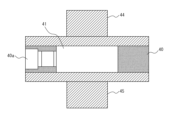
- FIG. 1 is a longitudinal sectional view schematically showing a compressor 100 according to Embodiment 1.
- FIG. FIG. 2 is a cross-sectional view schematically showing one end surface side A of the cylinder 40 at the top dead center, which is the compression mechanism portion 4 of the compressor 100 according to Embodiment 1.
- FIG. 3 is a cross-sectional view schematically showing the compression mechanism portion 4 of the compressor 100 according to Embodiment 1 and showing the other end surface side B of the cylinder 40 at the top dead center.
- FIG. 1 is a longitudinal sectional view schematically showing a compressor 100 according to Embodiment 1.
- FIG. FIG. 2 is a cross-sectional view schematically showing one end surface side A of the cylinder 40 at the top dead center, which is the compression mechanism portion 4 of the compressor 100 according to Embodiment 1.
- FIG. 3 is a cross-sectional view schematically showing the compression mechanism portion 4 of the compressor 100 according to Embodiment 1 and showing the other end surface side B of the cylinder 40 at the top dead
- FIG. 4 is a cross-sectional view schematically showing one end surface side A of the cylinder 40 at the bottom dead center, which is the compression mechanism portion 4 of the compressor 100 according to Embodiment 1.
- FIG. 5 is a cross-sectional view of the compression mechanism portion 4 of the compressor 100 according to Embodiment 1, schematically showing the other end surface side B of the cylinder 40 at the bottom dead center.
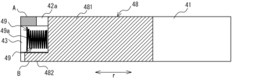
- FIG. 6 is a side view schematically showing a portion of cylinder 40 of compressor 100 according to Embodiment 1, in which vane groove 42 and vane spring housing hole 43 are formed.
- FIG. 7 is a longitudinal sectional view schematically showing a portion of cylinder 40 of compressor 100 according to Embodiment 1, in which vane groove 42 and vane spring housing hole 43 are formed.
- FIG. 8 is a longitudinal sectional view schematically showing a portion of cylinder 40 of compressor 100 according to Embodiment 1, in which suction port 40a is formed.
- the compressor 100 according to Embodiment 1 is a fluid machine that sucks a low-temperature, low-pressure refrigerant inside, compresses the sucked-in refrigerant, and discharges a high-temperature, high-pressure refrigerant to the outside.
- a compressor 100 shown in FIG. 1 is a single rotary compressor having one cylinder 40 as an example.
- the compressor 100 is not limited to a single rotary compressor, and may be a rotary compressor having a plurality of cylinders 40, such as a twin rotary compressor having two cylinders 40, or may have another structure. .
- a twin rotary compressor or the like having a high flow rate and high capacity is suitable.
- the compressor 100 includes, as shown in FIG. and a compression mechanism portion 4 that compresses the refrigerant by driving force transmitted from the rotating shaft 3 .
- a compression mechanism portion 4 that compresses the refrigerant by driving force transmitted from the rotating shaft 3 .
- the electric motor part 2 is housed in the upper part inside the sealed container 1 .
- the compression mechanism part 4 is accommodated in the lower part inside the sealed container 1 .
- the electric motor section 2 and the compression mechanism section 4 are connected via the rotating shaft 3 .
- the closed container 1 is composed of an upper container 10 and a lower container 11 .
- the sealed container 1 is not limited to being formed from two components, the upper container 10 and the lower container 11, and may be formed from three or more components.
- the sealed container 1 is connected to a suction muffler 101 via a refrigerant suction pipe 12, and gas refrigerant is taken into the interior from the suction muffler 101.
- the intake muffler 101 is fixed to the outer surface of the lower container 11 of the closed container 1 by welding or the like.
- the suction muffler 101 separates the low-temperature, low-pressure refrigerant sent from the refrigeration circuit into liquid refrigerant and gas refrigerant, and prevents the liquid refrigerant from being sucked into the compression mechanism 4 as much as possible, and stores the separated liquid refrigerant. is provided to do so.
- Intake muffler 101 also functions as a muffler that reduces or eliminates noise generated by the inflowing refrigerant.
- a refrigerant discharge pipe 13 for discharging the compressed refrigerant is connected to the upper portion of the sealed container 1 .
- the refrigerant discharge pipe 13 is a refrigerant pipe for discharging a high-pressure gas refrigerant to the outside of the sealed container 1 .
- the refrigerant discharge pipe 13 is joined to the upper container 10 by, for example, brazing or resistance welding while passing through the upper container 10 constituting the closed container 1 .
- the inside of the sealed container 1 is filled with high-temperature and high-pressure gas refrigerant compressed by the compression mechanism 4, and refrigerating machine oil 14 used for lubricating the compression mechanism 4 is stored at the bottom.
- Refrigerating machine oil 14 is mainly used to lubricate sliding portions of compression mechanism 4 .
- An oil pump (not shown) is provided below the rotary shaft 3 . The oil pump pumps up the refrigerating machine oil 14 stored in the bottom portion of the closed container 1 as the rotating shaft 3 rotates, and supplies the oil to each sliding portion of the compression mechanism portion 4 .
- the compression mechanism 4 ensures mechanical lubrication by supplying oil to each sliding portion.
- the electric motor unit 2 is provided rotatably facing the cylindrical stator 20 fixed to the inner wall surface of the closed container 1 by shrink fitting or the like, and the inner surface of the stator 20. and a cylindrical rotor 21 that rotates by magnetic action.
- a rotary shaft 3 is fitted in the center of the rotor 21 .
- the electric motor unit 2 uses electric power supplied from an external power source to generate a rotational driving force on the rotating shaft 3 and transmits the rotational driving force to the compression mechanism unit 4 via the rotating shaft 3 .
- a brushless DC motor or the like is used for the electric motor unit 2, for example.
- the rotary shaft 3 includes a main shaft portion 30 fixed to the rotor 21 of the electric motor portion 2, a sub-shaft portion 31 provided on the opposite side of the main shaft portion 30 across the compression mechanism portion 4, the main shaft portion 30 and the sub-shaft portion. and an eccentric shaft portion 32 provided between the portion 31 .
- the rotary shaft 3 is formed in the order of a main shaft portion 30, an eccentric shaft portion 32, and a sub shaft portion 31 from above to below the sealed container 1 in the axial direction.
- the main shaft portion 30 is fitted into the center portion of the rotor 21 of the electric motor portion 2 and fixed by shrink fitting or press fitting.
- the central axis of the eccentric shaft portion 32 is eccentric with respect to the central axes of the main shaft portion 30 and the sub shaft portion 31 .
- the compression mechanism section 4 compresses the low-pressure gas refrigerant sucked into the low-pressure space of the sealed container 1 from the refrigerant suction pipe 12 into a high-pressure gas refrigerant by the rotational driving force supplied from the electric motor section 2.
- the high-pressure gas refrigerant compressed by the compression mechanism portion 4 is discharged into the sealed container 1 from above the compression mechanism portion 4 .
- the compression mechanism 4 includes a cylinder 40, an upper bearing 44, a lower bearing 45, a discharge muffler 46, a rolling piston 47, a vane 48, and a vane spring 49. I have.
- the outer periphery of the cylinder 40 is fixed to the sealed container 1 with bolts or the like.
- the cylinder 40 has an upper surface as one end surface side A and a lower surface as the other end surface side B.
- the cylinder 40 has a hollow cylindrical shape, and the hollow interior is a cylinder chamber 41 .
- the cylinder chamber 41 is open at both ends in the axial direction of the rotating shaft 3 . is blocked by That is, the cylinder chamber 41 is a space surrounded by the inner peripheral surface of the cylinder 40 , the inner wall surface of the upper bearing 44 and the inner wall surface of the lower bearing 45 .
- the cylinder 40 is provided with a suction port 40a through which the gas refrigerant from the refrigerant suction pipe 12 passes, penetrating the cylinder chamber 41 from the outer peripheral surface.
- the intake port 40 a communicates the pipeline of the refrigerant intake pipe 12 and the cylinder chamber 41 .
- the cylinder 40 is formed with a vane groove 42 that communicates with the cylinder chamber 41 and extends in the radial direction r about the rotating shaft 3 .
- the vane groove 42 penetrates the cylinder 40 in the axial direction from one end surface side A to the other end surface side B when viewed from the direction in which the outer shape of the cylinder 40 appears circular.
- a vane 48 that divides the cylinder chamber 41 into a suction chamber 41 a and a compression chamber 41 b is slidably fitted in the vane groove 42 .
- the suction chamber 41a is a low-pressure space and communicates with the suction port 40a.
- the compression chamber 41b is a high-pressure space and communicates with a discharge port 44a (see FIG. 1) for discharging the cylinder chamber 41 to the outside.
- a stop portion 42 a is formed at the end of the vane groove 42 on the outer peripheral surface side of the cylinder 40 .
- the stop portion 42 a is provided to stop the movement of the vane 48 toward the outer peripheral surface of the cylinder 40 and limit the movement of the vane 48 so that the vane 48 does not protrude from the outer peripheral surface of the cylinder 40 .
- the stop portion 42a also has a function of introducing high-pressure refrigerant as a back pressure chamber. As shown in FIGS. 2 and 4, the stop portion 42a has an arc shape that opens only to the vane groove 42 when viewed from the one end surface side A of the cylinder 40. As shown in FIG.
- the cylinder 40 is formed with a vane spring housing hole 43 as a space for housing the vane spring 49 and operating the vane spring 49 .
- the vane spring housing hole 43 is formed so as to extend in the radial direction r of the cylinder 40 .
- the vane spring housing hole 43 penetrates the outer peripheral surface of the cylinder 40 and does not penetrate the inner peripheral surface of the cylinder 40 .
- the length of the vane spring housing hole 43 is determined according to the shape of the vane spring 49 to be operated or the shape of the cylinder 40 .
- the upper bearing 44 is formed in a substantially inverted T shape when viewed from the side.
- the upper bearing 44 is provided on one end surface of the cylinder 40 on the side where the electric motor section 2 is arranged, and closes one opening of the cylinder chamber 41 in the axial direction.
- the upper bearing 44 is fitted to the main shaft portion 30 of the rotating shaft 3 and supports the main shaft portion 30 rotatably.
- the upper bearing 44 is fixed to the cylinder 40 with a common screw 5 together with the lower bearing 45 .
- the upper bearing 44 is formed with a discharge port 44 a for discharging the refrigerant compressed in the compression chamber 41 b to the outside of the cylinder chamber 41 .
- a discharge valve (not shown) is attached to the discharge port 44a.
- the discharge valve is controlled at the timing of discharging the high-temperature and high-pressure gas refrigerant from the compression chamber 41b through the discharge port 44a. Specifically, the discharge valve closes the discharge port 44a when the pressure inside the compression chamber 41b is lower than the pressure inside the closed container 1 . Further, when the pressure inside the compression chamber 41b becomes higher than the pressure inside the closed container 1, the pressure inside the compression chamber 41b pushes the discharge valve upward.
- the lower bearing 45 is formed in a substantially T shape when viewed from the side.
- the lower bearing 45 is provided on the other end face of the cylinder 40 opposite to the side on which the electric motor section 2 is arranged, and closes the other axial opening of the cylinder chamber 41 . Further, the lower bearing 45 is fitted to the sub-shaft portion 31 of the rotating shaft 3 and rotatably supports the sub-shaft portion 31 .
- the discharge muffler 46 is attached so as to cover the outer side of the upper bearing 44, as shown in FIG. Inside the compression chamber 41b, the actions of sucking the refrigerant, compressing the refrigerant, and discharging the refrigerant are repeated. The compressed gas refrigerant is intermittently discharged from the discharge port 44a. As a result, noise such as pulsating noise may be generated from the cylinder 40 .
- the discharge muffler 46 is provided to suppress noise such as pulsating noise generated from the cylinder 40 .
- the discharge muffler 46 is provided with a discharge hole (not shown) that communicates the space formed by the discharge muffler 46 and the upper bearing 44 with the inside of the sealed container 1 .
- the gas refrigerant discharged from the cylinder 40 through the discharge port 44a is once discharged into the space formed by the discharge muffler 46 and the upper bearing 44, and then discharged into the sealed container 1 through the discharge hole.
- the rolling piston 47 is formed in a hollow cylindrical shape, and the eccentric shaft portion 32 of the rotating shaft 3 is slidably fitted in the hollow interior.
- the rolling piston 47 is housed in the cylinder chamber 41 together with the eccentric shaft portion 32 .
- the rolling piston 47 rotates along the inner peripheral surface of the cylinder chamber 41 and compresses the refrigerant when the rotating shaft 3 is rotated by driving the electric motor portion 2 .
- the vanes 48 move inside the vane grooves 42 following the rotation of the rolling piston 47 while the tips are kept in contact with the outer peripheral surface of the rolling piston 47 during the refrigerant compression process. slide back and forth.
- the cylinder chamber 41 is partitioned into a suction chamber 41 a and a compression chamber 41 b by contacting the outer peripheral surface of the rolling piston 47 with the tip of the vane 48 .
- the vanes 48 are made of, for example, a non-magnetic material.
- the vane spring 49 contacts the rear side of the vane 48 and presses the vane 48 so that the tip of the vane 48 contacts the outer peripheral surface of the rolling piston 47 .
- the vane spring 49 is housed in the vane spring housing hole 43 of the cylinder 40 and arranged in series with the vane 48 . As shown in FIG. 7, the vane spring 49 is fixed to the cylinder 40 by the end turn 49a press-fitted inside the vane spring housing hole 43 coming into contact with the inner wall surface of the vane spring housing hole 43. .
- the method for fixing the vane spring 49 to the cylinder 40 is not limited to this method.
- the high-pressure gas refrigerant inside the sealed container 1 flows into the stop portion 42a, and the pressure difference between the pressure of the gas refrigerant in the stop portion 42a and the pressure of the gas refrigerant in the cylinder chamber 41 causes , create a force that moves the vane 48 in the radial direction r toward the center of the cylinder chamber 41 .
- the pressure difference between the pressure of the gas refrigerant at the stop portion 42a and the pressure of the gas refrigerant inside the cylinder chamber 41 is sufficient to press the vane 48 against the outer peripheral surface of the rolling piston 47. It may not be pressure. Even in such a case, the vane 48 can be pressed toward the rolling piston 47 by the force of the vane spring 49 in the compression mechanism 4, so that the tip of the vane 48 is always in contact with the outer peripheral surface of the rolling piston 47.
- the rolling piston 47 rotates together with the eccentric shaft portion 32 inside the cylinder chamber 41 when the rotary shaft 3 is rotated by driving the electric motor portion 2 .
- a suction chamber 41a partitioned by the vanes 48 increases in volume as the rotating shaft 3 rotates. Also, in the cylinder chamber 41, the volume of the compression chamber 41b partitioned by the vane 48 is reduced.
- the suction chamber 41a communicates with the suction port 40a, and low-pressure gas refrigerant is sucked into the cylinder chamber 41.
- the communication between the compression chamber 41b and the suction port 40a is closed by the rolling piston 47, and the gas refrigerant inside the compression chamber 41b is compressed as the volume of the compression chamber 41b decreases.
- the compression chamber 41b communicates with the discharge port 44a of the upper bearing 44, and after the gas refrigerant inside the compression chamber 41b reaches a predetermined pressure, the discharge valve provided at the discharge port 44a is opened and compressed. The gas refrigerant that has become high pressure and high temperature is discharged to the outside of the cylinder chamber 41 .
- the high-pressure and high-temperature gas refrigerant discharged to the outside of the cylinder chamber 41 is discharged into the sealed container 1 via the discharge muffler 46 . Then, the discharged gas refrigerant passes through the inside of the electric motor part 2, rises inside the closed container 1, and is discharged to the outside of the closed container 1 from the refrigerant discharge pipe 13 provided in the upper part of the closed container 1. be done.
- the refrigerant discharged to the outside of the sealed container 1 circulates through the refrigeration circuit and returns to the suction muffler 101 again.
- low GWP (Global Warming Potential) refrigerants such as R32, R1234yf, or R290 have been used as refrigerants for refrigeration cycle devices equipped with compressors as one of the measures against global warming.
- low GWP refrigerants have a smaller refrigerating capacity per volume than conventionally used refrigerants such as R410A. Therefore, in the refrigerating cycle device, it is necessary to increase the flow rate of the refrigerant flowing inside in order to achieve the desired refrigerating capacity.
- the stroke volume is the amount of refrigerant discharged per rotation of the compression mechanism 4 . In order to increase this stroke volume, it is desirable to increase the inner diameter of the cylinder chamber 41 .
- the compressor 100 even if the inner diameter of the cylinder chamber 41 of the cylinder 40 is increased to increase the amount of protrusion of the vane 48 that projects into the cylinder chamber 41, the pressure from the high pressure chamber to the low pressure chamber is increased. It has a configuration that can suppress the occurrence of refrigerant leakage and seizure.
- the vane groove 42 has an opening 42b formed at one end positioned on the inner peripheral side of the cylinder 40. As shown in FIGS. 2 and 3, the vane groove 42 does not penetrate to the outer peripheral surface of the cylinder 40 on the one end surface side A of the cylinder 40, which is the upper surface of the cylinder 40, and is formed on the outer peripheral surface side of the cylinder 40. A stop portion 42a for the vane 48 is formed at the end. On the other hand, as shown in FIGS. 4 and 5, the vane groove 42 is formed through the outer peripheral surface of the cylinder 40 on the other end surface side B of the cylinder 40 which is the lower surface of the cylinder 40 .
- the vane groove 42 functions as a stop portion 42a only on the one end surface side A of the cylinder 40 .
- the vane spring storage hole 43 has a perfect circular cross-sectional shape perpendicular to the direction in which the vane spring storage hole 43 extends. It becomes a shape that communicates.
- the one end surface side A is the upper surface of the cylinder 40 and the other end surface side B is the lower surface of the cylinder 40, but the one end surface side A is the lower surface of the cylinder 40 and the other end surface side B is the upper surface of the cylinder 40. good too.
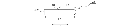
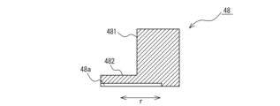
- FIG. 9 is a top view schematically showing the vane 48 of the compressor 100 according to Embodiment 1.
- FIG. FIG. 10 is a longitudinal sectional view of vane 48 shown in FIG.
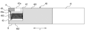
- FIG. 11 is a vertical cross-sectional view of a portion of the compression mechanism portion 4 of the compressor 100 according to Embodiment 1, schematically showing a state in which the vane 48 is arranged at the top dead center phase.
- FIG. 12 is a vertical cross-sectional view of a portion of the compression mechanism portion 4 of the compressor 100 according to Embodiment 1, schematically showing a state in which the vane 48 is arranged at the phase of the bottom dead center.
- the vane 48 penetrates the outer peripheral surface of the portion 481 located on the one end surface side A of the cylinder 40 in which the stop portion 42a is formed, along the radial direction r.
- the length Lb along the radial direction r of the portion 482 positioned on the other end surface side B of the cylinder 40 is longer. That is, the vane 48 has a non-rectangular parallelepiped shape.
- the length of vanes 48 is defined by the construction of cylinder 40 .
- the vane 48 that follows the rolling piston 47 does not protrude from the inner peripheral surface of the cylinder chamber 41 when the rolling piston 47 is positioned at the top dead center phase, as shown in FIGS. It is completely housed in the vane groove 42.
- the top dead center phase is when the rolling piston 47 is positioned in the vane groove 42 phase, as shown in FIGS.
- the rear side of the vane 48 does not contact the stop 42a at the portion 481 located on the one end surface side A of the cylinder 40, and the cylinder A portion 482 located on the other end surface side B of the cylinder 40 does not protrude from the outer peripheral surface of the cylinder 40 .
- the vane 48 is sized so as not to protrude outside from the outer peripheral surface of the cylinder 40 when it is separated from the rolling piston 47 and pressed against the stop portion 42a.
- the vane 48 temporarily follows the rolling piston 47 in order to prevent damage or failure of the components of the compression mechanism 4 due to overload due to liquid compression. is canceled.
- the rear surface side of the vane 48 on the one end surface side A of the cylinder 40 is pressed against the stop portion 42a by the pressure from the high-pressure liquid refrigerant.
- the rear surface side of the vane 48 in the portion 482 positioned on the other end surface side B of the cylinder 40 does not protrude from the outer peripheral surface of the cylinder 40 to the outside.
- the compressor 100 according to Embodiment 1 if the total length of the vane 48 at the portion 482 located on the other end surface side B of the cylinder 40 is Lb, 2e/Lb ⁇ 0.5 have a relationship That is, the vane 48 is defined such that the ratio of the amount of protrusion into the cylinder chamber 41 (protrusion ratio) to the total length is less than 50%. With this provision, the sliding reciprocating motion of the vane 48 can be kept stable.
- the compressor 100 can ensure a long overall length of the vanes 48 and can increase the protrusion amount of the vanes 48, so that high flow rate, high capacity and high reliability can be obtained.
- the length La of the vane 48 on the one end surface side A of the cylinder 40 2e/La ⁇ 0.5 or 2e/La ⁇ 0.5 may be
- FIG. 13 is a side view schematically showing a first modification of the cylinder 40 of the compressor 100 according to the first embodiment, in which the vane grooves 42 and the vane spring housing holes 43 are formed.
- the vane spring housing hole 43 may be formed by offsetting the central axis P from the center O of the cylinder 40 in the thickness direction toward the one end surface side A of the cylinder 40 .
- the direction of this offset is the direction in which the length of the stop portion 42a is shortened.
- the length of the vane 48 along the radial direction r of the cylinder 40 is longer at the portion 482 located at the other end surface side B of the cylinder 40 than at the portion 481 located at the one end surface side A of the cylinder 40 .
- the side area of the vane 48 can be increased by shortening the length of the stop portion 42a formed on the one end surface side A of the cylinder 40 .
- the compressor 100 can sufficiently support the differential pressure between the high-pressure refrigerant and the low-pressure refrigerant, thereby further improving reliability.
- FIG. 14 is a side view schematically showing a second modified example of the cylinder 40 of the compressor 100 according to the first embodiment, in which the vane grooves 42 and the vane spring housing holes 43 are formed.
- FIG. 15 is a longitudinal sectional view schematically showing a second modification of the cylinder 40 of the compressor 100 according to the first embodiment, in which the vane grooves 42 and the vane spring housing holes 43 are formed.
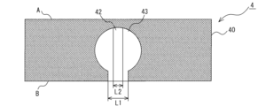
- the stop portion 42a is projected onto the other end surface side B of the cylinder 40 as viewed from the one end surface side A of the cylinder 40, the outer peripheral surface of the cylinder 40 is projected from a point 420a where the stop portion 42a is projected.
- a groove width L1 of the vane groove 42 in the distance X is formed larger than a groove width L2 of the vane groove 42 in the distance Y from the projected portion 420a of the stop portion 42a to the inner peripheral surface of the cylinder 40 .
- the processing of the vane grooves 42 can be easily performed.
- the term "from the point 420a where the stop portion 42a is projected" may be anywhere within the range of the projected point 420a.
- the vane groove 42 must be formed so that the flatness is less than 10 [ ⁇ m], and high processing accuracy is required. Therefore, it is difficult to machine the vane grooves 42 with the same flatness from the inner peripheral surface to the outer peripheral surface of the cylinder 40 .
- the vane groove 42 has a plane X between a point 420a where the stop portion 42a is projected and the outer peripheral surface of the cylinder 40, and a plane Y between a point 420a where the stop portion 42a is projected and the inner peripheral surface of the cylinder 40. and are formed as separate planes, processing becomes easier.
- the sliding conditions of the vane 48 and the vane groove 42 are the severest when the rolling piston 47 is in the phase of the bottom dead center.
- the portion X from the point 420a where the stop portion 42a is projected to the outer peripheral surface of the cylinder 40 has a low contribution rate to the sliding conditions. Therefore, in the compressor 100, there is a plane X between a point 420a where the stop 42a is projected and the outer peripheral surface of the cylinder 40, and a plane Y between the point 420a where the stop 42a is projected and the inner peripheral surface of the cylinder 40. Even if it is machined as a separate plane from the sliding surface, it has little effect on the sliding conditions.
- FIG. 16 is an explanatory diagram schematically showing Modification 1 of the vane 48 in the compressor 100 according to Embodiment 1.
- FIG. FIG. 17 is a longitudinal sectional view of vane 48 shown in FIG.
- the vane 48 may have an introduction groove 48a formed in the end surface of the portion 482 located on the other end surface side B of the cylinder 40 for introducing the high-pressure gas refrigerant.
- the introduction groove 48 a is formed along the radial direction r of the cylinder 40 .
- the vane 48 has an asymmetrical structure between a portion 481 located on one end surface side A of the cylinder 40 and a portion 482 located on the other end surface side B of the cylinder 40.
- the vane 48 performs an unbalanced reciprocating motion, resulting in local sliding. It may come into direct contact with the surface, causing seizure and galling.
- the vane 48 is provided with the introduction groove 48a for the high-pressure gas refrigerant, so that a load can be applied from above and below the cylinder 40, and the balance of the entire reciprocating motion can be improved.
- the introduction groove 48 a communicates with the back surface side of the vane 48 , but does not communicate with the tip end side that contacts the rolling piston 47 .
- the vane 48 may have a configuration in which the introduction groove 48a is formed in the end surface of the portion 481 located on the one end surface side A of the cylinder 40, or the portion 481 located on the one end surface side A of the cylinder 40 and the other end surface side.
- a configuration in which the introduction grooves 48a are formed in both end surfaces of the portion 482 located at B may be employed.
- FIG. 18 is an explanatory view schematically showing Modification 2 of vane 48 in compressor 100 according to Embodiment 1.
- FIG. FIG. 19 is an explanatory diagram schematically showing Modification 3 of vane 48 in the compressor according to Embodiment 1.
- the entire rear surface of the portion 481 located on the one end surface side A of the cylinder 40 where the stop portion 42a is formed is formed into an R shape 48b.
- the stop portion 42a In the compressor 100 according to Embodiment 1, only one end surface side A of the cylinder 40 is provided with the stop portion 42a. As such, the stop 42a has a shorter length to receive the vane 48 than in conventional compressors.
- the vane 48 may have a rounded shape 48b only at the corners of the rear surface of the portion 481 located on the one end surface side of the cylinder 40 where the stop portion 42a is formed.
- FIG. 20 is an explanatory diagram schematically showing Modification 4 of vanes 48 in compressor 100 according to Embodiment 1.
- FIG. The vane 48 shown in FIG. 20 has a central portion 483 extending along the radial direction r of the cylinder 40 between a portion 481 located on one end surface side A of the cylinder 40 and a portion 482 located on the other end surface side B. is provided.
- the central portion 483 is configured to be inserted inside the vane spring 49, and when the rolling piston 47 is positioned at the top dead center phase, the back surface thereof is located closer to the outer peripheral surface side of the cylinder 40 than the end turn 49a of the vane spring 49. ing. Since the vane 48 shown in FIG. 20 has a central portion 483, the side area can be increased, so that the load of the refrigerant differential pressure applied in the direction from the compression chamber 41b (high pressure) to the suction chamber 41a (low pressure) can be reduced. I can support it enough.
- the dimensions of the cylinder 40 in the compressor 100 according to Embodiment 1 will be explained.
- the dimensions of the cylinder 40 shown below are an example, and are not limited to the dimensions.
- the thickness of the cylinder 40 is, for example, 30 [mm].
- the outer diameter of the cylinder 40 is assumed to be 130 [mm].
- the inner diameter of the cylinder 40 is assumed to be 60 [mm].
- the difference in radius between the inner diameter and the outer diameter of the cylinder 40 is 35 [mm].
- the diameter of the vane spring housing hole 43 is 14 [mm].
- the width of the vane groove 42 and the vane 48 is 4 [mm].
- a clearance formed by the vane groove 42 and the vane 48 is 30 [ ⁇ m].
- the diameter of the stop portion 42a is 9 [mm].
- the width of the vane 48 is 4 [mm]
- the groove width of the introduction groove 48a is 2 [mm]
- the depth is It is 1 [mm].
- the length La of the portion 481 located on the one end surface side A of the cylinder 40 is 30 mm
- the length Lb of the portion 482 located on the other end surface side B of the cylinder 40 is 34.4 mm. [mm].
- the distance to the interference between the stop portion 42a and the back surface of the vane 48 is 0.5 [mm]. Therefore, as long as the vane 48 keeps following the rolling piston 47, the vane 48 does not come into contact with the stop portion 42a.
- the vane 48 is still positioned so that the rear surface of the portion 482 located on the other end surface side B of the cylinder 40 Do not protrude outside from the outer peripheral surface of
- the compressor 100 includes the closed container 1 forming the outer shell, the electric motor section 2 having the stator 20 and the rotor 21, and the electric motor section 2 connected to the rotor 21. and a compression mechanism 4 connected to the rotating shaft 3 for compressing the refrigerant by the driving force transmitted from the rotating shaft 3 .
- the rotating shaft 3 has an eccentric shaft portion 32 .
- the compression mechanism portion 4 is fixed to the sealed container 1 and is fitted with a cylinder 40 having a cylinder chamber 41 into which refrigerant is sucked and compressed, and an eccentric shaft portion 32 which is accommodated in the cylinder chamber 41 .
- the vane 48 has a length Lb along the radial direction r of the portion 482 located on the other end surface side B of the cylinder 40 that is longer than the length La along the radial direction r of the portion 481 located on the one end surface side A of the cylinder 40 . is considered to be longer.
- the amount of protrusion of the vanes 48 into the cylinder chamber 41 relative to the total length of the vanes 48 can be reduced, and the side area of the vanes 48 can be increased. Therefore, even if the inner diameter of the cylinder chamber 41 of the cylinder 40 is increased to increase the amount of protrusion of the vane 48, it is possible to suppress refrigerant leakage and seizure from the high-pressure compression chamber 41b to the low-pressure suction chamber 41a. .
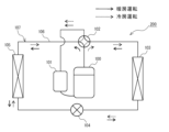
- FIG. 21 is a refrigeration circuit diagram of refrigeration cycle apparatus 200 including compressor 100 according to Embodiment 1. As shown in FIG. 21
- the refrigeration cycle apparatus 200 includes a compressor 100, a flow path switching device 102, an outdoor heat exchanger 103, an expansion mechanism 104, an indoor heat exchanger 105, and an intake
- the muffler 101 has a refrigerating circuit 107 which is sequentially connected by a refrigerant pipe 106 and in which the refrigerant circulates.
- R407C refrigerant, R410A refrigerant, R32 refrigerant, or the like is used as the refrigerant flowing through the refrigeration circuit 107 .
- the efficiency of the compressor 100 can be further improved by using a low GWP refrigerant such as R1234yf refrigerant or R290 refrigerant.
- the channel switching device 102 is, for example, a four-way valve and has a function of switching the coolant channel.
- the flow switching device 102 connects the refrigerant discharge side of the compressor 100 and the gas side of the outdoor heat exchanger 103, and also connects the refrigerant suction side of the compressor 100 and the indoor heat exchanger 105. Switch the refrigerant flow path so as to connect the gas side.
- the flow switching device 102 connects the refrigerant discharge side of the compressor 100 and the gas side of the indoor heat exchanger 105, and connects the refrigerant suction side of the compressor 100 to the outdoor heat exchanger.
- the refrigerant flow path is switched so as to connect the gas side of 103 .
- the flow path switching device 102 may be configured by combining two-way valves or three-way valves.
- the outdoor heat exchanger 103 functions as a condenser during cooling operation, and performs heat exchange between the refrigerant discharged from the compressor 100 and flowing inside and the outdoor air. Further, the outdoor heat exchanger 103 functions as an evaporator during heating operation, and performs heat exchange between the refrigerant flowing out from the expansion mechanism 104 and flowing inside and the outdoor air.
- the outdoor heat exchanger 103 draws in outdoor air using an air blower (not shown) and discharges the air heat-exchanged with the refrigerant to the outside.
- the expansion mechanism 104 decompresses and expands the refrigerant that has flowed out of the condenser, and is composed of, for example, an electronic expansion valve that can adjust the opening of a throttle.
- the expansion mechanism 104 controls the pressure of the refrigerant flowing into the outdoor heat exchanger 103 or the indoor heat exchanger 105 by adjusting the degree of opening.
- the indoor heat exchanger 105 functions as an evaporator during cooling operation, and performs heat exchange between the refrigerant flowing out from the expansion mechanism 104 and flowing inside and the indoor air.
- the indoor heat exchanger 105 functions as a condenser during heating operation, and performs heat exchange between the refrigerant discharged from the compressor 100 and flowing inside and the indoor air.
- the indoor-side heat exchanger 105 draws in indoor air using an air blower (not shown), and supplies the air, which has been heat-exchanged with the refrigerant, indoors.
- the pipes connected to the flow path switching device 102 are connected so as to form a circuit on the solid line side in FIG.
- the high-temperature and high-pressure gas refrigerant discharged from the compressor 100 passes through the flow path switching device 102 and flows to the indoor heat exchanger 105, exchanges heat with air, and is condensed and liquefied.
- the condensed and liquefied refrigerant is decompressed by the expansion mechanism 104 to become a low-temperature, low-pressure gas-liquid two-phase refrigerant, flows to the outdoor heat exchanger 103, exchanges heat with air, and is gasified.
- the gasified refrigerant passes through the flow switching device 102 and is sucked into the compressor 100 via the suction muffler 101 .
- the pipes connected to the flow path switching device 102 are connected to each other so as to form a circuit on the dashed line side in FIG.
- the high-temperature and high-pressure gas refrigerant discharged from the compressor 100 passes through the flow path switching device 102 and flows to the outdoor heat exchanger 103, exchanges heat with the air, and condenses and liquefies.
- the condensed and liquefied refrigerant is decompressed by the expansion mechanism 104 to become a low-temperature, low-pressure gas-liquid two-phase refrigerant, flows to the indoor heat exchanger 105, exchanges heat with air, and is gasified.
- the gasified refrigerant passes through the flow switching device 102 and is sucked into the compressor 100 via the suction muffler 101 .
- a refrigeration cycle device 200 includes the compressor 100 according to the first embodiment. Therefore, refrigeration cycle device 200 can obtain the same effects as compressor 100 according to the first embodiment.
- FIG. FIG. 22 is a compression mechanism portion 4 of the compressor 100 according to Embodiment 2, and is a cross-sectional view schematically showing the other end surface side B of the cylinder 40 in a state where the rolling piston 47 is at the top dead center.
- FIG. 23 schematically shows the compression mechanism portion 4 of the compressor 100 according to Embodiment 2, and the other end surface side B of the cylinder 40 in a state where the phase of the rolling piston 47 is 90° with respect to the top dead center.
- 1 is a cross sectional view shown; FIG. FIG.
- FIG. 24 is a cross-sectional view schematically showing the other end surface side B of the cylinder 40, which is a modification of the compression mechanism portion 4 of the compressor 100 according to Embodiment 2.
- FIG. 25 is a side view schematically showing a portion of cylinder 40 of compressor 100 according to Embodiment 2, in which vane groove 42 and vane spring housing hole 43 are formed.
- the same components as those of the compressor 100 described in Embodiment 1 are denoted by the same reference numerals, and the description thereof will be omitted as appropriate.
- the sealed container 1 is formed with through holes 10a at positions corresponding to the vane grooves 42, in which the vanes 48 can slide.
- the through hole 10 a is closed from the outer peripheral surface side of the closed container 1 by a closing component 15 which is a separate component from the closed container 1 .
- Other configurations are the same as those of the compressor 100 described in the first embodiment.
- the vane 48 when the rolling piston 47 is positioned at the top dead center phase, the vane 48 has a portion located on the other end surface side B of the cylinder 40 extending from the outer peripheral surface of the cylinder 40 to the through hole 10a. protrude.
- the length of the vanes 48 in the radial direction r of the cylinder 40 can be increased.
- the compressor 100 by increasing the total length of the vanes 48, the sliding conditions of the vanes 48 and the vane grooves 42 can be relaxed, so pressure loss can be reduced, compressor efficiency can be improved, and reliability can be further improved. improves.
- the compressor 100 according to Embodiment 2 is not limited to the configuration in which the closed container 1 is formed with the through hole 10a. As shown in FIG. 24, pressing or the like may be performed to form recesses 10b in which the vanes 48 can rub on the inner wall surface of the sealed container 1, thereby forming a configuration corresponding to the through holes 10a.
- the vane 48 protrudes from the outer peripheral surface of the cylinder 40 into the recess 10b when the rolling piston 47 is positioned at the top dead center phase.
- the compressor 100 it is necessary to increase the force of the vane springs 49 that press the vanes 48 by increasing the total length of the vanes 48 . If the pressing load of the vane spring 49 is insufficient, the vane 48 and the rolling piston 47 are separated near the bottom dead center, the partition between the suction chamber 41a and the compression chamber 41b is released, and the efficiency of the compressor 100 may decrease. be. Therefore, as shown in FIG. 25, the cylinder 40 is formed with a groove portion 43 a extending from the vane spring housing hole 43 toward the cylinder chamber 41 . The vane spring 49 is slidably fitted inside the groove portion 43a.
- the configuration in which the groove portion 43a is formed in the vane spring housing hole 43 is not limited to the configuration of the second embodiment, and can also be applied to the other first or third embodiments.
- the vane 48 does not protrude from the outer peripheral surface of the cylinder 40 when the revolution phase of the rolling piston 47 is 180° with respect to the top dead center. dimensions are desirable. This is because, although the total length of the vane 48 is limited, it is difficult to attach the compression mechanism 4 to the closed container 1 if the vane 48 always protrudes from the outer peripheral surface of the cylinder 40 .
- the vane 48 is desirably sized such that the rear side thereof does not protrude from the outer peripheral surface of the cylinder 40 .
- the rolling pistons 47 provided in the respective cylinders 40 rotate with 180° different revolution phases. In other words, with the above configuration, it is possible to prevent the rear side of any of the vanes 48 of the two cylinders 40 from constantly protruding from the outer peripheral surface of the cylinder 40 to the outside.
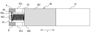
- FIG. FIG. 26 is a vertical cross-sectional view schematically showing cylinder 40 of compressor 100 according to Embodiment 3, in which vane 48 is arranged at the top dead center phase.
- FIG. 27 is a top view schematically showing vane 48 of compressor 100 according to the third embodiment.
- 28 is a cross-sectional view taken along the line CC shown in FIG. 27.
- FIG. The same components as those of the compressor 100 described in Embodiments 1 and 2 are denoted by the same reference numerals, and description thereof will be omitted as appropriate.
- the vane grooves 42 do not penetrate to the outer peripheral surface side of the cylinder 40 on one end surface side A of the two opposing end surfaces of the cylinder 40 , but extend to the end portion on the outer peripheral surface side of the cylinder 40 .
- a first stop 42c of the vane 48 is formed.
- the vane groove 42 does not penetrate to the outer peripheral surface of the cylinder 40 on the other end surface side B of the cylinder 40, and a second stopping portion 42d of the vane 48 is formed at the end portion on the outer peripheral surface side of the cylinder 40.
- the vane groove 42 has stop portions 42 c and 42 d formed on one end surface side A and the other end surface side B of the cylinder 40 .
- the vane spring storage hole 43 has a perfect circular cross-sectional shape perpendicular to the direction in which the vane spring storage hole 43 extends.
- the vane 48 has a portion 481 located on one end surface side A of the cylinder 40 where the first stop portion 42c is formed and the other end surface side B where the second stop portion 42d is formed.
- a central portion 483 extending along the radial direction r of the cylinder 40 is provided between the portion 482 located at the .
- the central portion 483 is such that the length Lc along the radial direction r of the cylinder 40 is equal to the length La along the radial direction r of the portion 481 located on the one end surface side A of the cylinder 40 and the portion 482 located on the other end surface side B of the cylinder 40 . It is longer than the length Lb in the radial direction r.
- the vane 48 is formed such that the length La of the portion 481 located on the one end surface side A of the cylinder 40 and the length Lb of the portion 482 located on the other end surface side B are substantially equal. Further, as shown in FIG. 26, the central portion 483 is configured to be inserted inside the vane spring 49, and when the rolling piston 47 is arranged at the phase of the top dead center, the back surface of the vane spring 49 reaches the end turn 49a of the vane spring 49. is positioned closer to the outer peripheral surface of the cylinder 40 than the .
- the length La of the portion 481 located on the one end surface side A of the cylinder 40 and the length Lb of the portion 482 located on the other end surface side B of the vane 48 are substantially equal to each other. Since they are formed with the same length, the vertical balance during the reciprocating motion of the vane 48 can be stabilized.
- the vane groove 42 is also provided with two stop portions 42c and 42d. Therefore, even when the vane 48 comes into contact with the stop portions 42c and 42d, the vertical balance of the vane 48 can be stabilized.
- the vane 48 has the central portion 483, the side area of the vane 48 can be increased. can support
- Either one or both of the end faces of 482 may be formed with introduction grooves 48a for introducing high-pressure gas refrigerant.
- the vane 48 may have an R shape 48b on the entire back surface of a portion 481 located on the one end surface side A of the cylinder 40 where the first stop portion 42c is formed. Further, the vane 48 may have an R shape 48b on the entire back surface of the portion 482 located on the other end surface side B of the cylinder 40 where the second stop portion 42d is formed. Further, as shown in FIG. 19, for example, the vane 48 may have a curved shape 48b only at the corners of the rear surface of the portion 481 located on the one end surface side A of the cylinder 40 where the first stop portion 42c is formed. Also, the vane 48 may have a rounded shape 48b only at the rear corner of the portion 481 located on the other end surface side B of the cylinder 40 where the second stop portion 42d is formed.
- the compressor 100 and the refrigeration cycle device 200 have been described above based on the embodiment, they are not limited to the configurations of the embodiment described above.
- the compressor 100 and the refrigeration cycle device 200 are not limited to the illustrated configurations, and may include other components.
- the compressor 100 and the refrigerating cycle device 200 include a range of design changes and application variations that are normally made by those skilled in the art within a range that does not deviate from the technical idea thereof.
Abstract
This compressor is provided with a closed container, an electric motor unit, a crankshaft, and a compression mechanism unit. The crankshaft has an eccentric shaft part. The compression mechanism unit comprises: a cylinder having a cylinder chamber into which a refrigerant is suctioned and compressed; a rolling piston that is fitted with the eccentric shaft part and is accommodated in the cylinder chamber, and that rotates with the eccentric shaft part to compress the refrigerant; and a vane that is provided in a vane groove formed in a radial direction of the cylinder and that follows the rolling piston to thereby partition the cylinder chamber into a suction chamber and a compression chamber for the refrigerant. The vane groove does not penetrate through to the outer peripheral surface of the cylinder on one end surface side of the cylinder. A vane stop part is formed at an end on the outer peripheral surface side of the cylinder. On the other end surface side of the cylinder, the vane groove is formed to penetrate through the outer peripheral surface of the cylinder. The vane is so configured that the length of a portion thereof positioned on the other end surface side of the cylinder on which the outer peripheral surface is penetrated through is longer than the length of a portion thereof positioned on the one end surface side of the cylinder at which the vane stop part is formed.
Description
本開示は、圧縮機及び該圧縮機を備えた冷凍サイクル装置に関するものである。
The present disclosure relates to a compressor and a refrigeration cycle device provided with the compressor.
従来、例えば特許文献1に開示された圧縮機のように、密閉容器と、電動機部と、回転軸と、圧縮機構部と、を備えた構成が知られている。圧縮機構部は、シリンダ室を有するシリンダと、回転軸の偏心軸部に嵌合されてシリンダ室に収納され、偏心軸部と共に回転して冷媒を圧縮するローリングピストンと、シリンダの径方向に形成されたベーン溝に設けられ、ローリングピストンに追従してシリンダ室を冷媒の吸入室と圧縮室とに仕切るベーンと、を有している。
Conventionally, there is known a configuration including a sealed container, an electric motor section, a rotating shaft, and a compression mechanism section, such as the compressor disclosed in Patent Document 1, for example. The compression mechanism includes a cylinder having a cylinder chamber, a rolling piston that is accommodated in the cylinder chamber by being fitted to the eccentric shaft portion of the rotating shaft, rotates together with the eccentric shaft portion to compress the refrigerant, and is formed in the radial direction of the cylinder. and a vane provided in the vane groove formed in the cylinder and following the rolling piston to divide the cylinder chamber into a refrigerant suction chamber and a compression chamber.
近年、地球温暖化対策の1つとして、圧縮機を備えた冷凍サイクル装置の冷媒に、例えば、R32、R1234yfあるいはR290等の低GWP(Global Warming Potential)冷媒が用いられている。しかし、低GWP冷媒は、R410A等の従来使用されてきた冷媒と比較して体積あたりの冷凍能力が小さい。このため、冷凍サイクル装置では、所望の冷凍能力を達成させるため、内部に流れる冷媒の流量を多くする必要がある。冷媒の流量の増加させるためには、圧縮室のストロークボリュームを増加させることが効果的である。ストロークボリュームとは、圧縮機構部が1回転当たりに吐出する冷媒量である。そして、このストロークボリュームを増加させるためには、シリンダ室の内径を拡大することが望ましい。
In recent years, low GWP (Global Warming Potential) refrigerants such as R32, R1234yf or R290 have been used as refrigerants in refrigeration cycle devices equipped with compressors as one of the measures against global warming. However, low GWP refrigerants have a smaller refrigerating capacity per volume than conventionally used refrigerants such as R410A. Therefore, in the refrigerating cycle device, it is necessary to increase the flow rate of the refrigerant flowing inside in order to achieve the desired refrigerating capacity. Increasing the stroke volume of the compression chamber is effective in increasing the flow rate of the refrigerant. The stroke volume is the amount of refrigerant discharged per rotation of the compression mechanism. In order to increase this stroke volume, it is desirable to increase the inner diameter of the cylinder chamber.
しかしながら、特許文献1に開示されたような従来の圧縮機において、シリンダ室の内径を拡大すると、シリンダ室へ突出するベーンの突出量が増加する。ベーンは、全長に対してシリンダ室への突出量が大きいと、動作が不安定になり、ローリングピストンへの追従性が悪化する。その結果、圧縮機は、シリンダ室における高圧室から低圧室への冷媒漏れが発生し、圧縮効率が低下するおそれがある。また、高圧室から低圧室の方向へかかる冷媒差圧の荷重を支えるベーンの側面積が小さくなるので、厳しい摺動条件下となり、焼き付きが発生して圧縮機の故障の原因となる。
However, in the conventional compressor disclosed in Patent Document 1, if the inner diameter of the cylinder chamber is increased, the amount of protrusion of the vane that protrudes into the cylinder chamber increases. If the amount of protrusion into the cylinder chamber is large relative to the total length of the vane, the operation becomes unstable, and the ability to follow the rolling piston deteriorates. As a result, the compressor may leak refrigerant from the high-pressure chamber to the low-pressure chamber in the cylinder chamber, and the compression efficiency may decrease. In addition, since the side area of the vane that supports the load of the refrigerant differential pressure applied from the high pressure chamber to the low pressure chamber becomes smaller, severe sliding conditions are created, causing seizure and failure of the compressor.
本開示は、上記のような課題を解決するためになされたものであり、シリンダのシリンダ室の内径を拡大して、シリンダ室へ突出するベーンの突出量が増加しても、高圧室から低圧室への冷媒漏れ及び焼き付きの発生を抑制できる、圧縮機及び該圧縮機を備えた冷凍サイクル装置を提供することを目的とする。
The present disclosure has been made in order to solve the above-described problems. It is an object of the present invention to provide a compressor and a refrigeration cycle device having the compressor that can suppress the occurrence of refrigerant leakage and seizure into a chamber.
本開示に係る圧縮機は、外郭を形成する密閉容器と、固定子及び回転子を有する電動機部と、前記回転子に接続され、前記電動機部の駆動力を伝達する回転軸と、前記回転軸に接続され、前記回転軸から伝達される駆動力によって冷媒を圧縮する圧縮機構部と、を備え、前記回転軸は、偏心軸部を有しており、前記圧縮機構部は、前記密閉容器に固定され、冷媒が吸入されて圧縮されるシリンダ室を有するシリンダと、前記偏心軸部に嵌合されて前記シリンダ室に収納され、前記偏心軸部と共に回転して冷媒を圧縮するローリングピストンと、前記シリンダの径方向に形成されたベーン溝に設けられ、前記ローリングピストンに追従して前記シリンダ室を冷媒の吸入室と圧縮室とに仕切るベーンと、を有し、前記ベーン溝は、前記シリンダの対向する2つの端面のうち一端面側において、前記シリンダの外周面まで貫通することなく、前記シリンダの外周面側における端部に前記ベーンの止まり部が形成され、前記シリンダの他端面側において、前記シリンダの外周面を貫通して形成されており、前記ベーンは、前記シリンダの前記一端面側に位置する部分の前記径方向に沿う長さよりも、前記シリンダの前記他端面側に位置する部分の前記径方向に沿う長さの方が長い構成とされているものである。
A compressor according to the present disclosure includes a closed container forming an outer shell, an electric motor section having a stator and a rotor, a rotating shaft connected to the rotor and transmitting a driving force of the electric motor section, and the rotating shaft and a compression mechanism that compresses the refrigerant by driving force transmitted from the rotating shaft, the rotating shaft having an eccentric shaft, and the compression mechanism that is connected to the sealed container. a cylinder that is fixed and has a cylinder chamber into which refrigerant is sucked and compressed; a rolling piston that is fitted to the eccentric shaft portion and accommodated in the cylinder chamber and rotates together with the eccentric shaft portion to compress the refrigerant; a vane provided in a vane groove formed in a radial direction of the cylinder and following the rolling piston to divide the cylinder chamber into a refrigerant suction chamber and a compression chamber, the vane groove being formed in the cylinder. The vane stop portion is formed at the end of the outer peripheral surface of the cylinder without penetrating to the outer peripheral surface of the cylinder on one end surface side of the two opposing end surfaces of the cylinder, and on the other end surface side of the cylinder , the vane is formed to penetrate the outer peripheral surface of the cylinder, and the vane is located closer to the other end surface of the cylinder than the length along the radial direction of the portion located on the one end surface side of the cylinder. The length along the radial direction of the portion is configured to be longer.
本開示に係る冷凍サイクル装置は、少なくとも、上記圧縮機と、内部を流れる冷媒と室外空気との間で熱交換を行う室外側熱交換器と、内部を流れる冷媒と室内空気との間で熱交換を行う室内側熱交換器と、前記室外側熱交換器又は前記室内側熱交換器に流入する冷媒を膨張させる膨張機構と、が冷媒配管を介して接続された冷凍回路を有するものである。
The refrigeration cycle device according to the present disclosure includes at least the compressor, an outdoor heat exchanger that exchanges heat between the refrigerant flowing inside and the outdoor air, and heat between the refrigerant flowing inside and the indoor air. A refrigerating circuit in which an indoor heat exchanger for exchange and an expansion mechanism for expanding refrigerant flowing into the outdoor heat exchanger or the indoor heat exchanger are connected via refrigerant pipes. .
本開示によれば、ベーンは、止まり部が形成されたシリンダの一端面側に位置する部分の径方向に沿う長さよりも、外周面を貫通したシリンダの他端面側に位置する部分の径方向に沿う長さの方が長い。よって、ベーンの全長に対するベーンのシリンダ室への突出量を小さくでき、且つベーンの側面積を大きくできるので、シリンダのシリンダ室の内径を拡大して、ベーンの突出量を増加させても、高圧室から低圧室への冷媒漏れ及び焼き付きの発生を抑制できる。
According to the present disclosure, the vane has a length in the radial direction of the portion located on the other end surface side of the cylinder penetrating the outer peripheral surface rather than the length along the radial direction of the portion located on the one end surface side of the cylinder in which the stop portion is formed. length along is longer. Therefore, the amount of protrusion of the vane into the cylinder chamber relative to the total length of the vane can be reduced, and the side area of the vane can be increased. Refrigerant leakage from the chamber to the low-pressure chamber and occurrence of seizure can be suppressed.
以下、図面を参照して、本開示の実施の形態について説明する。なお、各図中、同一又は相当する部分には、同一符号を付して、その説明を適宜省略又は簡略化する。また、各図に記載の構成について、その形状、大きさ、及び配置等は、適宜変更することができる。
Embodiments of the present disclosure will be described below with reference to the drawings. In each figure, the same or corresponding parts are denoted by the same reference numerals, and the description thereof will be omitted or simplified as appropriate. Further, the shape, size, arrangement, etc. of the configuration described in each drawing can be changed as appropriate.
実施の形態1.
先ず、本実施の形態1に係る圧縮機100について説明する。図1は、実施の形態1に係る圧縮機100を概略的に示した縦断面図である。図2は、実施の形態1に係る圧縮機100の圧縮機構部4であって、上死点におけるシリンダ40の一端面側Aを概略的に示した横断面図である。図3は、実施の形態1に係る圧縮機100の圧縮機構部4であって、上死点におけるシリンダ40の他端面側Bを概略的に示した横断面図である。図4は、実施の形態1に係る圧縮機100の圧縮機構部4であって、下死点におけるシリンダ40の一端面側Aを概略的に示した横断面図である。図5は、実施の形態1に係る圧縮機100の圧縮機構部4であって、下死点におけるシリンダ40の他端面側Bを概略的に示した横断面図である。図6は、実施の形態1に係る圧縮機100のシリンダ40であって、ベーン溝42及びベーンスプリング収納穴43が形成された部分を概略的に示した側面図である。図7は、実施の形態1に係る圧縮機100のシリンダ40であって、ベーン溝42及びベーンスプリング収納穴43が形成された部分を概略的に示した縦断面図である。図8は、実施の形態1に係る圧縮機100のシリンダ40であって、吸入ポート40aが形成された部分を概略的に示した縦断面図である。Embodiment 1.
First, acompressor 100 according to Embodiment 1 will be described. FIG. 1 is a longitudinal sectional view schematically showing a compressor 100 according to Embodiment 1. FIG. FIG. 2 is a cross-sectional view schematically showing one end surface side A of the cylinder 40 at the top dead center, which is the compression mechanism portion 4 of the compressor 100 according to Embodiment 1. As shown in FIG. FIG. 3 is a cross-sectional view schematically showing the compression mechanism portion 4 of the compressor 100 according to Embodiment 1 and showing the other end surface side B of the cylinder 40 at the top dead center. FIG. 4 is a cross-sectional view schematically showing one end surface side A of the cylinder 40 at the bottom dead center, which is the compression mechanism portion 4 of the compressor 100 according to Embodiment 1. As shown in FIG. FIG. 5 is a cross-sectional view of the compression mechanism portion 4 of the compressor 100 according to Embodiment 1, schematically showing the other end surface side B of the cylinder 40 at the bottom dead center. FIG. 6 is a side view schematically showing a portion of cylinder 40 of compressor 100 according to Embodiment 1, in which vane groove 42 and vane spring housing hole 43 are formed. FIG. 7 is a longitudinal sectional view schematically showing a portion of cylinder 40 of compressor 100 according to Embodiment 1, in which vane groove 42 and vane spring housing hole 43 are formed. FIG. 8 is a longitudinal sectional view schematically showing a portion of cylinder 40 of compressor 100 according to Embodiment 1, in which suction port 40a is formed.
先ず、本実施の形態1に係る圧縮機100について説明する。図1は、実施の形態1に係る圧縮機100を概略的に示した縦断面図である。図2は、実施の形態1に係る圧縮機100の圧縮機構部4であって、上死点におけるシリンダ40の一端面側Aを概略的に示した横断面図である。図3は、実施の形態1に係る圧縮機100の圧縮機構部4であって、上死点におけるシリンダ40の他端面側Bを概略的に示した横断面図である。図4は、実施の形態1に係る圧縮機100の圧縮機構部4であって、下死点におけるシリンダ40の一端面側Aを概略的に示した横断面図である。図5は、実施の形態1に係る圧縮機100の圧縮機構部4であって、下死点におけるシリンダ40の他端面側Bを概略的に示した横断面図である。図6は、実施の形態1に係る圧縮機100のシリンダ40であって、ベーン溝42及びベーンスプリング収納穴43が形成された部分を概略的に示した側面図である。図7は、実施の形態1に係る圧縮機100のシリンダ40であって、ベーン溝42及びベーンスプリング収納穴43が形成された部分を概略的に示した縦断面図である。図8は、実施の形態1に係る圧縮機100のシリンダ40であって、吸入ポート40aが形成された部分を概略的に示した縦断面図である。
First, a
本実施の形態1に係る圧縮機100は、低温且つ低圧の冷媒を内部に吸入し、吸入した冷媒を圧縮して、高温且つ高圧の冷媒を外部に吐出する流体機械である。図1に示す圧縮機100は、一例としてシリンダ40を1つ有するシングルロータリ圧縮機である。なお、圧縮機100は、シングルロータリ圧縮機に限定されるものではなく、例えばシリンダ40を2つ有するツインロータリ圧縮機等、複数のシリンダ40を有するロータリ圧縮機でもよいし、他の構造でもよい。因みに、高流量の冷媒を流す圧縮機では、冷媒の吸入経路における圧力損失を効果的に低減させる必要があるため、高流量及び高能力を有するツインロータリ圧縮機等が好適である。
The compressor 100 according to Embodiment 1 is a fluid machine that sucks a low-temperature, low-pressure refrigerant inside, compresses the sucked-in refrigerant, and discharges a high-temperature, high-pressure refrigerant to the outside. A compressor 100 shown in FIG. 1 is a single rotary compressor having one cylinder 40 as an example. Note that the compressor 100 is not limited to a single rotary compressor, and may be a rotary compressor having a plurality of cylinders 40, such as a twin rotary compressor having two cylinders 40, or may have another structure. . Incidentally, in a compressor through which a high flow rate of refrigerant flows, it is necessary to effectively reduce the pressure loss in the refrigerant suction path, so a twin rotary compressor or the like having a high flow rate and high capacity is suitable.
本実施の形態1に係る圧縮機100は、図1に示すように、外郭を形成する密閉容器1と、固定子20及び回転子21を有する電動機部2と、電動機部2の駆動力を伝達する回転軸3と、回転軸3から伝達される駆動力によって冷媒を圧縮する圧縮機構部4と、を備えている。密閉容器1の内部には、電動機部2、回転軸3及び圧縮機構部4が収容されている。電動機部2は、密閉容器1の内部の上方に収容されている。圧縮機構部4は、密閉容器1の内部の下方に収容されている。電動機部2と圧縮機構部4は、回転軸3を介して連結されている。
The compressor 100 according to the first embodiment includes, as shown in FIG. and a compression mechanism portion 4 that compresses the refrigerant by driving force transmitted from the rotating shaft 3 . Inside the sealed container 1, an electric motor section 2, a rotating shaft 3, and a compression mechanism section 4 are accommodated. The electric motor part 2 is housed in the upper part inside the sealed container 1 . The compression mechanism part 4 is accommodated in the lower part inside the sealed container 1 . The electric motor section 2 and the compression mechanism section 4 are connected via the rotating shaft 3 .
密閉容器1は、上部容器10と下部容器11とにより構成されている。なお、密閉容器1は、上部容器10と下部容器11との2つの構成部材から形成されるものに限定されるものではなく、3つ以上の構成部材で形成してもよい。
The closed container 1 is composed of an upper container 10 and a lower container 11 . The sealed container 1 is not limited to being formed from two components, the upper container 10 and the lower container 11, and may be formed from three or more components.
密閉容器1は、図1に示すように、冷媒吸入管12を介して吸入マフラ101と接続されており、吸入マフラ101からガス冷媒が内部に取り込まれる。吸入マフラ101は、溶接等により密閉容器1の下部容器11の外側面に固定されている。吸入マフラ101は、冷凍回路から送られてくる低温且つ低圧の冷媒を液冷媒とガス冷媒とに分離し、液冷媒がなるべく圧縮機構部4に吸入されないようにすると共に、分離した液冷媒を貯留するために設けられている。圧縮機100は、圧縮機構部4に液冷媒が流入して圧縮されてしまうと、該圧縮機構部4の故障の原因となるからである。また、吸入マフラ101は、流入する冷媒により発生する騒音を低減又は除去する消音器としての機能も有する。
As shown in FIG. 1, the sealed container 1 is connected to a suction muffler 101 via a refrigerant suction pipe 12, and gas refrigerant is taken into the interior from the suction muffler 101. The intake muffler 101 is fixed to the outer surface of the lower container 11 of the closed container 1 by welding or the like. The suction muffler 101 separates the low-temperature, low-pressure refrigerant sent from the refrigeration circuit into liquid refrigerant and gas refrigerant, and prevents the liquid refrigerant from being sucked into the compression mechanism 4 as much as possible, and stores the separated liquid refrigerant. is provided to do so. This is because if the liquid refrigerant flows into the compression mechanism portion 4 and is compressed, the compressor 100 may cause the compression mechanism portion 4 to malfunction. Intake muffler 101 also functions as a muffler that reduces or eliminates noise generated by the inflowing refrigerant.
密閉容器1の上部には、圧縮された冷媒を排出させる冷媒吐出管13が接続されている。冷媒吐出管13は、高圧のガス冷媒を密閉容器1の外部に吐出させる冷媒配管である。冷媒吐出管13は、密閉容器1を構成する上部容器10を貫通した状態で、例えばろう付け又は抵抗溶接等によって上部容器10に接合されている。
A refrigerant discharge pipe 13 for discharging the compressed refrigerant is connected to the upper portion of the sealed container 1 . The refrigerant discharge pipe 13 is a refrigerant pipe for discharging a high-pressure gas refrigerant to the outside of the sealed container 1 . The refrigerant discharge pipe 13 is joined to the upper container 10 by, for example, brazing or resistance welding while passing through the upper container 10 constituting the closed container 1 .
密閉容器1の内部は、圧縮機構部4によって圧縮された高温且つ高圧のガス冷媒によって満たされているとともに、底部に圧縮機構部4の潤滑に用いられる冷凍機油14が貯留されている。冷凍機油14は、主に圧縮機構部4の摺動部を潤滑するために用いられる。回転軸3の下部にはオイルポンプ(図示は省略)が設けられている。オイルポンプは、回転軸3の回転とともに密閉容器1の底部に貯留された冷凍機油14を汲み上げ、圧縮機構部4の各摺動部へ供給する。圧縮機構部4は、各摺動部への給油によって機械的な潤滑作用が確保される。
The inside of the sealed container 1 is filled with high-temperature and high-pressure gas refrigerant compressed by the compression mechanism 4, and refrigerating machine oil 14 used for lubricating the compression mechanism 4 is stored at the bottom. Refrigerating machine oil 14 is mainly used to lubricate sliding portions of compression mechanism 4 . An oil pump (not shown) is provided below the rotary shaft 3 . The oil pump pumps up the refrigerating machine oil 14 stored in the bottom portion of the closed container 1 as the rotating shaft 3 rotates, and supplies the oil to each sliding portion of the compression mechanism portion 4 . The compression mechanism 4 ensures mechanical lubrication by supplying oil to each sliding portion.
電動機部2は、図1に示すように、密閉容器1の内壁面に焼き嵌め等によって固定された円筒形状の固定子20と、固定子20の内側面に対向して回転可能に設けられ、磁気作用によって回転する円筒形状の回転子21と、を有している。回転子21の中心部には、回転軸3が嵌入されている。電動機部2は、外部電源から供給された電力を用いて回転軸3に回転駆動力を発生させ、回転軸3を介して回転駆動力を圧縮機構部4に伝達する。なお、電動機部2には、例えばブラシレスDCモータ等が用いられる。
As shown in FIG. 1, the electric motor unit 2 is provided rotatably facing the cylindrical stator 20 fixed to the inner wall surface of the closed container 1 by shrink fitting or the like, and the inner surface of the stator 20. and a cylindrical rotor 21 that rotates by magnetic action. A rotary shaft 3 is fitted in the center of the rotor 21 . The electric motor unit 2 uses electric power supplied from an external power source to generate a rotational driving force on the rotating shaft 3 and transmits the rotational driving force to the compression mechanism unit 4 via the rotating shaft 3 . A brushless DC motor or the like is used for the electric motor unit 2, for example.
回転軸3は、電動機部2の回転子21に固定された主軸部30と、圧縮機構部4を挟んで主軸部30の反対側に設けられた副軸部31と、主軸部30と副軸部31との間に設けられた偏心軸部32と、を有している。回転軸3は、軸方向において、密閉容器1の上方から下方に向かって主軸部30、偏心軸部32、副軸部31の順に形成されている。主軸部30は、電動機部2の回転子21の中心部に嵌め込まれ、焼嵌又は圧入されて固定されている。偏心軸部32は、中心軸が主軸部30及び副軸部31の中心軸に対して偏心している。
The rotary shaft 3 includes a main shaft portion 30 fixed to the rotor 21 of the electric motor portion 2, a sub-shaft portion 31 provided on the opposite side of the main shaft portion 30 across the compression mechanism portion 4, the main shaft portion 30 and the sub-shaft portion. and an eccentric shaft portion 32 provided between the portion 31 . The rotary shaft 3 is formed in the order of a main shaft portion 30, an eccentric shaft portion 32, and a sub shaft portion 31 from above to below the sealed container 1 in the axial direction. The main shaft portion 30 is fitted into the center portion of the rotor 21 of the electric motor portion 2 and fixed by shrink fitting or press fitting. The central axis of the eccentric shaft portion 32 is eccentric with respect to the central axes of the main shaft portion 30 and the sub shaft portion 31 .
圧縮機構部4は、電動機部2から供給された回転駆動力により、冷媒吸入管12から密閉容器1の低圧空間に吸入された低圧のガス冷媒を高圧のガス冷媒に圧縮するものである。圧縮機構部4によって圧縮した高圧のガス冷媒は、圧縮機構部4の上方から密閉容器1の内部に吐出される。圧縮機構部4は、図1~図8に示すように、シリンダ40と、上軸受44と、下軸受45と、吐出マフラ46と、ローリングピストン47と、ベーン48と、ベーンスプリング49と、を備えている。
The compression mechanism section 4 compresses the low-pressure gas refrigerant sucked into the low-pressure space of the sealed container 1 from the refrigerant suction pipe 12 into a high-pressure gas refrigerant by the rotational driving force supplied from the electric motor section 2. The high-pressure gas refrigerant compressed by the compression mechanism portion 4 is discharged into the sealed container 1 from above the compression mechanism portion 4 . As shown in FIGS. 1 to 8, the compression mechanism 4 includes a cylinder 40, an upper bearing 44, a lower bearing 45, a discharge muffler 46, a rolling piston 47, a vane 48, and a vane spring 49. I have.
シリンダ40は、ボルト等によって外周部が密閉容器1に固定されている。シリンダ40は、図1に示すように、上面を一端面側Aとし、下面を他端面側Bとしている。シリンダ40は、図2~図5に示すように、中空円筒形状とされ、中空内部がシリンダ室41とされている。シリンダ室41は、図1に示すように、回転軸3の軸方向の両端が開口しており、シリンダ40の上面に設けられた上軸受44と、シリンダ40の下面に設けられた下軸受45とによって閉塞されている。つまり、シリンダ室41は、シリンダ40の内周面と、上軸受44の内壁面と、下軸受45の内壁面とによって囲まれた空間である。
The outer periphery of the cylinder 40 is fixed to the sealed container 1 with bolts or the like. As shown in FIG. 1, the cylinder 40 has an upper surface as one end surface side A and a lower surface as the other end surface side B. As shown in FIG. As shown in FIGS. 2 to 5, the cylinder 40 has a hollow cylindrical shape, and the hollow interior is a cylinder chamber 41 . As shown in FIG. 1 , the cylinder chamber 41 is open at both ends in the axial direction of the rotating shaft 3 . is blocked by That is, the cylinder chamber 41 is a space surrounded by the inner peripheral surface of the cylinder 40 , the inner wall surface of the upper bearing 44 and the inner wall surface of the lower bearing 45 .
また、図2~図5、図8に示すように、シリンダ40には、冷媒吸入管12からのガス冷媒が通る吸入ポート40aが、外周面からシリンダ室41に貫通して設けられている。吸入ポート40aは、冷媒吸入管12の管路とシリンダ室41とを連通させるものである。
As shown in FIGS. 2 to 5 and 8, the cylinder 40 is provided with a suction port 40a through which the gas refrigerant from the refrigerant suction pipe 12 passes, penetrating the cylinder chamber 41 from the outer peripheral surface. The intake port 40 a communicates the pipeline of the refrigerant intake pipe 12 and the cylinder chamber 41 .
また、シリンダ40には、図2~図7に示すように、シリンダ室41に連通し、回転軸3を中心とした径方向rに延びるベーン溝42が形成されている。ベーン溝42は、図2~図5に示すように、シリンダ40の外形が円に見える方向から見て、一端面側Aから他端面側Bに向かって、シリンダ40の軸方向に貫通している。ベーン溝42には、シリンダ室41を吸入室41aと圧縮室41bとに仕切るベーン48が、摺動可能に嵌入させて設けられている。吸入室41aは、低圧空間であり、吸入ポート40aと連通している。圧縮室41bは、高圧空間であり、シリンダ室41の外部へ吐出するための吐出ポート44a(図1を参照)と連通している。
In addition, as shown in FIGS. 2 to 7, the cylinder 40 is formed with a vane groove 42 that communicates with the cylinder chamber 41 and extends in the radial direction r about the rotating shaft 3 . As shown in FIGS. 2 to 5, the vane groove 42 penetrates the cylinder 40 in the axial direction from one end surface side A to the other end surface side B when viewed from the direction in which the outer shape of the cylinder 40 appears circular. there is A vane 48 that divides the cylinder chamber 41 into a suction chamber 41 a and a compression chamber 41 b is slidably fitted in the vane groove 42 . The suction chamber 41a is a low-pressure space and communicates with the suction port 40a. The compression chamber 41b is a high-pressure space and communicates with a discharge port 44a (see FIG. 1) for discharging the cylinder chamber 41 to the outside.
また、シリンダ40の外周面側におけるベーン溝42の端部には、止まり部42aが形成されている。止まり部42aは、ベーン48がシリンダ40の外周面から飛び出さないように、シリンダ40の外周面側に向かうベーン48の動きを止めて、ベーン48の動作を制限するために設けられている。また、止まり部42aは、背圧室として高圧冷媒を導入する機能も有する。なお、止まり部42aは、図2及び図4に示すように、シリンダ40の一端面側Aから見てベーン溝42にのみ開口する円弧形状である。
A stop portion 42 a is formed at the end of the vane groove 42 on the outer peripheral surface side of the cylinder 40 . The stop portion 42 a is provided to stop the movement of the vane 48 toward the outer peripheral surface of the cylinder 40 and limit the movement of the vane 48 so that the vane 48 does not protrude from the outer peripheral surface of the cylinder 40 . The stop portion 42a also has a function of introducing high-pressure refrigerant as a back pressure chamber. As shown in FIGS. 2 and 4, the stop portion 42a has an arc shape that opens only to the vane groove 42 when viewed from the one end surface side A of the cylinder 40. As shown in FIG.
また、シリンダ40には、図6及び図7に示すように、ベーンスプリング49を収納し、該ベーンスプリング49を動作させる空間としてベーンスプリング収納穴43が形成されている。ベーンスプリング収納穴43は、シリンダ40の径方向rに延びるように形成されている。ベーンスプリング収納穴43は、図7に示すように、シリンダ40の外周面を貫通し、シリンダ40の内周面を貫通していない。ベーンスプリング収納穴43の長さは、動作させるベーンスプリング49の形状、又はシリンダ40の形状に応じて決定される。
In addition, as shown in FIGS. 6 and 7, the cylinder 40 is formed with a vane spring housing hole 43 as a space for housing the vane spring 49 and operating the vane spring 49 . The vane spring housing hole 43 is formed so as to extend in the radial direction r of the cylinder 40 . As shown in FIG. 7 , the vane spring housing hole 43 penetrates the outer peripheral surface of the cylinder 40 and does not penetrate the inner peripheral surface of the cylinder 40 . The length of the vane spring housing hole 43 is determined according to the shape of the vane spring 49 to be operated or the shape of the cylinder 40 .
上軸受44は、図1に示すように、側面視で略逆T字形状に形成されている。上軸受44は、電動機部2が配置されている側のシリンダ40の一端面に設けられ、シリンダ室41の軸方向の一方の開口部を閉塞している。また、上軸受44は、回転軸3の主軸部30に嵌合され、主軸部30を回転可能に支持している。上軸受44は、下軸受45と共に、共通のねじ5によってシリンダ40に固定されている。
As shown in FIG. 1, the upper bearing 44 is formed in a substantially inverted T shape when viewed from the side. The upper bearing 44 is provided on one end surface of the cylinder 40 on the side where the electric motor section 2 is arranged, and closes one opening of the cylinder chamber 41 in the axial direction. The upper bearing 44 is fitted to the main shaft portion 30 of the rotating shaft 3 and supports the main shaft portion 30 rotatably. The upper bearing 44 is fixed to the cylinder 40 with a common screw 5 together with the lower bearing 45 .
なお、上軸受44には、圧縮室41bで圧縮された冷媒を、シリンダ室41の外部へ吐出するための吐出ポート44aが形成されている。吐出ポート44aには、吐出弁(図示省略)が取り付けられている。吐出弁は、高温且つ高圧のガス冷媒を圧縮室41bから吐出ポート44aを介して吐出させるタイミングで制御される。具体的には、吐出弁は、圧縮室41bの内部の圧力が密閉容器1の内部の圧力より低い時に、吐出ポート44aを閉塞する。また、吐出弁は、圧縮室41bの内部の圧力が密閉容器1の内部の圧力より高くなったときに、圧縮室41bの内部の圧力により上方向へ押し上げられる。
The upper bearing 44 is formed with a discharge port 44 a for discharging the refrigerant compressed in the compression chamber 41 b to the outside of the cylinder chamber 41 . A discharge valve (not shown) is attached to the discharge port 44a. The discharge valve is controlled at the timing of discharging the high-temperature and high-pressure gas refrigerant from the compression chamber 41b through the discharge port 44a. Specifically, the discharge valve closes the discharge port 44a when the pressure inside the compression chamber 41b is lower than the pressure inside the closed container 1 . Further, when the pressure inside the compression chamber 41b becomes higher than the pressure inside the closed container 1, the pressure inside the compression chamber 41b pushes the discharge valve upward.
下軸受45は、図1に示すように、側面視で略T字形状に形成されている。下軸受45は、電動機部2が配置されている側とは反対側のシリンダ40の他端面に設けられ、シリンダ室41の軸方向の他方の開口部を閉塞している。また、下軸受45は、回転軸3の副軸部31に嵌合され、副軸部31を回転可能に支持している。
As shown in FIG. 1, the lower bearing 45 is formed in a substantially T shape when viewed from the side. The lower bearing 45 is provided on the other end face of the cylinder 40 opposite to the side on which the electric motor section 2 is arranged, and closes the other axial opening of the cylinder chamber 41 . Further, the lower bearing 45 is fitted to the sub-shaft portion 31 of the rotating shaft 3 and rotatably supports the sub-shaft portion 31 .
吐出マフラ46は、図1に示すように、上軸受44の外側を覆うように取付けられている。圧縮室41bの内部では、冷媒を吸入し、冷媒を圧縮し、冷媒を吐出する動作が繰り返されている。圧縮されたガス冷媒は、吐出ポート44aから間欠的に吐出される。これにより、シリンダ40から脈動音などの騒音が発生する場合がある。吐出マフラ46は、このようなシリンダ40から発生される脈動音などの騒音を抑制するために設けられている。
The discharge muffler 46 is attached so as to cover the outer side of the upper bearing 44, as shown in FIG. Inside the compression chamber 41b, the actions of sucking the refrigerant, compressing the refrigerant, and discharging the refrigerant are repeated. The compressed gas refrigerant is intermittently discharged from the discharge port 44a. As a result, noise such as pulsating noise may be generated from the cylinder 40 . The discharge muffler 46 is provided to suppress noise such as pulsating noise generated from the cylinder 40 .
また、吐出マフラ46には、吐出マフラ46と上軸受44とによって形成される空間と、密閉容器1の内部とを連通させる吐出穴(図示は省略)が設けられている。シリンダ40から吐出ポート44aを介して吐出されるガス冷媒は、吐出マフラ46と上軸受44とによって形成される空間に一旦吐出され、その後、吐出穴から密閉容器1の内部へ吐出される。
Further, the discharge muffler 46 is provided with a discharge hole (not shown) that communicates the space formed by the discharge muffler 46 and the upper bearing 44 with the inside of the sealed container 1 . The gas refrigerant discharged from the cylinder 40 through the discharge port 44a is once discharged into the space formed by the discharge muffler 46 and the upper bearing 44, and then discharged into the sealed container 1 through the discharge hole.
ローリングピストン47は、図2~図5に示すように、中空円筒状に形成されており、中空内部に回転軸3の偏心軸部32が摺動可能に嵌合されている。ローリングピストン47は、偏心軸部32と共にシリンダ室41に収納されている。ローリングピストン47は、電動機部2の駆動によって回転軸3が回転すると、シリンダ室41の内周面に沿って回転して冷媒を圧縮する。
As shown in FIGS. 2 to 5, the rolling piston 47 is formed in a hollow cylindrical shape, and the eccentric shaft portion 32 of the rotating shaft 3 is slidably fitted in the hollow interior. The rolling piston 47 is housed in the cylinder chamber 41 together with the eccentric shaft portion 32 . The rolling piston 47 rotates along the inner peripheral surface of the cylinder chamber 41 and compresses the refrigerant when the rotating shaft 3 is rotated by driving the electric motor portion 2 .
ベーン48は、図2~図5に示すように、冷媒の圧縮工程中に、先端部がローリングピストン47の外周面に当接したまま、ローリングピストン47の回転に追従してベーン溝42の内部を往復摺動する。シリンダ室41は、ベーン48の先端部がローリングピストン47の外周面に当接することにより、吸入室41aと圧縮室41bとに仕切られる。ベーン48は、例えば非磁性材料で形成されている。
As shown in FIGS. 2 to 5, the vanes 48 move inside the vane grooves 42 following the rotation of the rolling piston 47 while the tips are kept in contact with the outer peripheral surface of the rolling piston 47 during the refrigerant compression process. slide back and forth. The cylinder chamber 41 is partitioned into a suction chamber 41 a and a compression chamber 41 b by contacting the outer peripheral surface of the rolling piston 47 with the tip of the vane 48 . The vanes 48 are made of, for example, a non-magnetic material.
ベーンスプリング49は、ベーン48の背面側と当接し、ベーン48の先端部がローリングピストン47の外周面に当接するようにベーン48を押圧するものである。ベーンスプリング49は、シリンダ40のベーンスプリング収納穴43に収納され、ベーン48と直列に配置されている。ベーンスプリング49は、図7に示すように、ベーンスプリング収納穴43の内部で圧入された座巻49aが、該ベーンスプリング収納穴43の内壁面に当接することによって、シリンダ40に固定されている。なお、ベーンスプリング49をシリンダ40に固定させる方法は、当該方法に限定されない。
The vane spring 49 contacts the rear side of the vane 48 and presses the vane 48 so that the tip of the vane 48 contacts the outer peripheral surface of the rolling piston 47 . The vane spring 49 is housed in the vane spring housing hole 43 of the cylinder 40 and arranged in series with the vane 48 . As shown in FIG. 7, the vane spring 49 is fixed to the cylinder 40 by the end turn 49a press-fitted inside the vane spring housing hole 43 coming into contact with the inner wall surface of the vane spring housing hole 43. . Note that the method for fixing the vane spring 49 to the cylinder 40 is not limited to this method.
上記構成の圧縮機構部4は、密閉容器1の内部の高圧のガス冷媒が止まり部42aに流入し、止まり部42aのガス冷媒の圧力と、シリンダ室41のガス冷媒の圧力との差圧により、シリンダ室41の中心に向って径方向rにベーン48を動かす力を作り出す。なお、圧縮機構部4は、止まり部42aのガス冷媒の圧力と、シリンダ室41の内部のガス冷媒の圧力との差圧が、ベーン48をローリングピストン47の外周面に押圧するために十分な圧力ではない場合がある。このような場合でも、圧縮機構部4では、ベーンスプリング49の力でベーン48をローリングピストン47に向かって押圧させることができるので、ベーン48の先端を、常にローリングピストン47の外周面に当接させることができる。
In the compression mechanism 4 configured as described above, the high-pressure gas refrigerant inside the sealed container 1 flows into the stop portion 42a, and the pressure difference between the pressure of the gas refrigerant in the stop portion 42a and the pressure of the gas refrigerant in the cylinder chamber 41 causes , create a force that moves the vane 48 in the radial direction r toward the center of the cylinder chamber 41 . In the compression mechanism 4, the pressure difference between the pressure of the gas refrigerant at the stop portion 42a and the pressure of the gas refrigerant inside the cylinder chamber 41 is sufficient to press the vane 48 against the outer peripheral surface of the rolling piston 47. It may not be pressure. Even in such a case, the vane 48 can be pressed toward the rolling piston 47 by the force of the vane spring 49 in the compression mechanism 4, so that the tip of the vane 48 is always in contact with the outer peripheral surface of the rolling piston 47. can be made
ここで、圧縮機100の動作について説明する。圧縮機100は、電動機部2の駆動によって回転軸3が回転運動することにより、シリンダ室41の内部で偏心軸部32と共にローリングピストン47が回転する。シリンダ室41において、ベーン48によって仕切られた吸入室41aは、回転軸3の回転とともに容積が増加する。また、シリンダ室41において、ベーン48によって仕切られた圧縮室41bは、容積が減少する。
Here, the operation of the compressor 100 will be described. In the compressor 100 , the rolling piston 47 rotates together with the eccentric shaft portion 32 inside the cylinder chamber 41 when the rotary shaft 3 is rotated by driving the electric motor portion 2 . In the cylinder chamber 41, a suction chamber 41a partitioned by the vanes 48 increases in volume as the rotating shaft 3 rotates. Also, in the cylinder chamber 41, the volume of the compression chamber 41b partitioned by the vane 48 is reduced.
圧縮機100は、吸入室41aと吸入ポート40aとが連通し、低圧のガス冷媒がシリンダ室41の内部に吸入される。次に、圧縮室41bと吸入ポート40aとの連通がローリングピストン47によって閉鎖され、圧縮室41bの容積減少とともに、圧縮室41bの内部のガス冷媒が圧縮される。最後に、圧縮室41bと上軸受44の吐出ポート44aとが連通し、圧縮室41bの内部のガス冷媒が所定の圧力に達した後、吐出ポート44aに設けられた吐出弁が開き、圧縮されて高圧且つ高温となったガス冷媒がシリンダ室41の外部へ吐出される。
In the compressor 100, the suction chamber 41a communicates with the suction port 40a, and low-pressure gas refrigerant is sucked into the cylinder chamber 41. Next, the communication between the compression chamber 41b and the suction port 40a is closed by the rolling piston 47, and the gas refrigerant inside the compression chamber 41b is compressed as the volume of the compression chamber 41b decreases. Finally, the compression chamber 41b communicates with the discharge port 44a of the upper bearing 44, and after the gas refrigerant inside the compression chamber 41b reaches a predetermined pressure, the discharge valve provided at the discharge port 44a is opened and compressed. The gas refrigerant that has become high pressure and high temperature is discharged to the outside of the cylinder chamber 41 .
シリンダ室41の外部へ吐出された高圧且つ高温のガス冷媒は、吐出マフラ46を介して、密閉容器1の内部に吐出される。そして、吐出されたガス冷媒は、電動機部2の内部を通過し、密閉容器1の内部を上昇して、密閉容器1の上部に設けられた冷媒吐出管13から、密閉容器1の外部へ吐出される。密閉容器1の外部へ吐出された冷媒は、冷凍回路を循環して、再び吸入マフラ101に戻ってくる。
The high-pressure and high-temperature gas refrigerant discharged to the outside of the cylinder chamber 41 is discharged into the sealed container 1 via the discharge muffler 46 . Then, the discharged gas refrigerant passes through the inside of the electric motor part 2, rises inside the closed container 1, and is discharged to the outside of the closed container 1 from the refrigerant discharge pipe 13 provided in the upper part of the closed container 1. be done. The refrigerant discharged to the outside of the sealed container 1 circulates through the refrigeration circuit and returns to the suction muffler 101 again.
ところで、近年、地球温暖化対策の1つとして、圧縮機を備えた冷凍サイクル装置の冷媒に、例えば、R32、R1234yfあるいはR290等の低GWP(Global Warming Potential)冷媒が用いられている。しかし、低GWP冷媒は、R410A等の従来使用されてきた冷媒と比較して体積あたりの冷凍能力が小さい。このため、冷凍サイクル装置では、所望の冷凍能力を達成させるため、内部に流れる冷媒の流量を多くする必要がある。冷媒の流量の増加させるためには、圧縮室41bのストロークボリュームを増加させることが効果的である。ストロークボリュームとは、圧縮機構部4が1回転当たりに吐出する冷媒量である。そして、このストロークボリュームを増加させるためには、シリンダ室41の内径を拡大することが望ましい。
By the way, in recent years, low GWP (Global Warming Potential) refrigerants such as R32, R1234yf, or R290 have been used as refrigerants for refrigeration cycle devices equipped with compressors as one of the measures against global warming. However, low GWP refrigerants have a smaller refrigerating capacity per volume than conventionally used refrigerants such as R410A. Therefore, in the refrigerating cycle device, it is necessary to increase the flow rate of the refrigerant flowing inside in order to achieve the desired refrigerating capacity. In order to increase the flow rate of the refrigerant, it is effective to increase the stroke volume of the compression chamber 41b. The stroke volume is the amount of refrigerant discharged per rotation of the compression mechanism 4 . In order to increase this stroke volume, it is desirable to increase the inner diameter of the cylinder chamber 41 .
しかしながら、シリンダ室41の内径を拡大すると、シリンダ室41へ突出するベーン48の突出量が増加する。ベーン48は、全長に対してシリンダ室41への突出量が大きいと、動作が不安定になり、ローリングピストン47への追従性が悪化する。その結果、圧縮機100は、シリンダ室41における圧縮室41b(高圧)から吸入室41a(低圧)への冷媒漏れが発生し、圧縮効率が低下するおそれがある。また、圧縮室41bから吸入室41aの方向へかかる冷媒差圧の荷重を支えるベーン48の側面積が小さくなるので、厳しい摺動条件下となり、焼き付きが発生して圧縮機100の故障の原因となる。
However, if the inner diameter of the cylinder chamber 41 is increased, the amount of protrusion of the vane 48 that protrudes into the cylinder chamber 41 increases. If the vane 48 protrudes into the cylinder chamber 41 by a large amount relative to the overall length, the operation becomes unstable, and the ability to follow the rolling piston 47 deteriorates. As a result, in the compressor 100, refrigerant leakage may occur from the compression chamber 41b (high pressure) in the cylinder chamber 41 to the suction chamber 41a (low pressure), and the compression efficiency may decrease. In addition, since the side area of the vane 48 that supports the load of the refrigerant differential pressure acting in the direction from the compression chamber 41b to the suction chamber 41a becomes smaller, severe sliding conditions occur, causing seizure and causing the compressor 100 to malfunction. Become.
そこで、本実施の形態1に係る圧縮機100では、シリンダ40のシリンダ室41の内径を拡大して、シリンダ室41へ突出するベーン48の突出量が増加しても、高圧室から低圧室への冷媒漏れ及び焼き付きの発生を抑制できる構成としている。
Therefore, in the compressor 100 according to the first embodiment, even if the inner diameter of the cylinder chamber 41 of the cylinder 40 is increased to increase the amount of protrusion of the vane 48 that projects into the cylinder chamber 41, the pressure from the high pressure chamber to the low pressure chamber is increased. It has a configuration that can suppress the occurrence of refrigerant leakage and seizure.
具体的は、ベーン溝42は、図2~図7に示すように、シリンダ40の内周側に位置する一方の端部に開口部42bが形成されている。また、ベーン溝42は、図2及び図3に示すように、シリンダ40の上面であるシリンダ40の一端面側Aにおいて、シリンダ40の外周面まで貫通することなく、シリンダ40の外周面側における端部にベーン48の止まり部42aが形成されている。一方、ベーン溝42は、図4及び図5に示すように、シリンダ40の下面であるシリンダ40の他端面側Bにおいて、シリンダ40の外周面を貫通して形成されている。つまり、ベーン溝42は、シリンダ40の一端面側Aのみが止まり部42aとして機能している。ベーンスプリング収納穴43は、図6に示すように、ベーンスプリング収納穴43の延びる方向に対して垂直な断面形状が、真円形状とされ、且つシリンダ40の他端面側Bにおけるベーン溝42が連通している形状となる。なお、図示例では一端面側Aをシリンダ40の上面とし、他端面側Bをシリンダ40の下面としているが、一端面側Aをシリンダ40の下面とし、他端面側Bをシリンダ40の上面としてもよい。
Specifically, as shown in FIGS. 2 to 7, the vane groove 42 has an opening 42b formed at one end positioned on the inner peripheral side of the cylinder 40. As shown in FIGS. 2 and 3, the vane groove 42 does not penetrate to the outer peripheral surface of the cylinder 40 on the one end surface side A of the cylinder 40, which is the upper surface of the cylinder 40, and is formed on the outer peripheral surface side of the cylinder 40. A stop portion 42a for the vane 48 is formed at the end. On the other hand, as shown in FIGS. 4 and 5, the vane groove 42 is formed through the outer peripheral surface of the cylinder 40 on the other end surface side B of the cylinder 40 which is the lower surface of the cylinder 40 . In other words, the vane groove 42 functions as a stop portion 42a only on the one end surface side A of the cylinder 40 . As shown in FIG. 6, the vane spring storage hole 43 has a perfect circular cross-sectional shape perpendicular to the direction in which the vane spring storage hole 43 extends. It becomes a shape that communicates. In the illustrated example, the one end surface side A is the upper surface of the cylinder 40 and the other end surface side B is the lower surface of the cylinder 40, but the one end surface side A is the lower surface of the cylinder 40 and the other end surface side B is the upper surface of the cylinder 40. good too.
図9は、実施の形態1に係る圧縮機100のベーン48を概略的に示した上面図である。図10は、図9に示したベーン48の縦断面図である。図11は、実施の形態1に係る圧縮機100の圧縮機構部4の一部であって、ベーン48が上死点の位相に配置された状態を概略的に示した縦断面図である。図12は、実施の形態1に係る圧縮機100の圧縮機構部4の一部であって、ベーン48が下死点の位相に配置された状態を概略的に示した縦断面図である。
FIG. 9 is a top view schematically showing the vane 48 of the compressor 100 according to Embodiment 1. FIG. FIG. 10 is a longitudinal sectional view of vane 48 shown in FIG. FIG. 11 is a vertical cross-sectional view of a portion of the compression mechanism portion 4 of the compressor 100 according to Embodiment 1, schematically showing a state in which the vane 48 is arranged at the top dead center phase. FIG. 12 is a vertical cross-sectional view of a portion of the compression mechanism portion 4 of the compressor 100 according to Embodiment 1, schematically showing a state in which the vane 48 is arranged at the phase of the bottom dead center.
ベーン48は、図9~図12に示すように、止まり部42aが形成されたシリンダ40の一端面側Aに位置する部分481の径方向rに沿う長さLaよりも、外周面を貫通したシリンダ40の他端面側Bに位置する部分482の径方向rに沿う長さLbほうが長い。つまり、ベーン48は、非直方体形状である。ベーン48の長さは、シリンダ40の構造によって規定される。ローリングピストン47に追従するベーン48は、図2、図3及び図11に示すように、ローリングピストン47が上死点の位相に配置されるとき、シリンダ室41の内周面から突出せず、ベーン溝42に完全に収納される。上死点の位相とは、図2、図3及び図11に示すように、ローリングピストン47がベーン溝42の位相に配置されるときである。上死点の位相において、ベーン48がローリングピストン47に追従している限り、ベーン48の背面側は、シリンダ40の一端面側Aに位置する部分481において、止まり部42aに接触せず、シリンダ40の他端面側Bに位置する部分482において、シリンダ40の外周面から外部に突出しない。
As shown in FIGS. 9 to 12, the vane 48 penetrates the outer peripheral surface of the portion 481 located on the one end surface side A of the cylinder 40 in which the stop portion 42a is formed, along the radial direction r. The length Lb along the radial direction r of the portion 482 positioned on the other end surface side B of the cylinder 40 is longer. That is, the vane 48 has a non-rectangular parallelepiped shape. The length of vanes 48 is defined by the construction of cylinder 40 . The vane 48 that follows the rolling piston 47 does not protrude from the inner peripheral surface of the cylinder chamber 41 when the rolling piston 47 is positioned at the top dead center phase, as shown in FIGS. It is completely housed in the vane groove 42. The top dead center phase is when the rolling piston 47 is positioned in the vane groove 42 phase, as shown in FIGS. In the top dead center phase, as long as the vane 48 follows the rolling piston 47, the rear side of the vane 48 does not contact the stop 42a at the portion 481 located on the one end surface side A of the cylinder 40, and the cylinder A portion 482 located on the other end surface side B of the cylinder 40 does not protrude from the outer peripheral surface of the cylinder 40 .
また、ベーン48は、ローリングピストン47から離間されて、止まり部42aに押し当てられた状態において、シリンダ40の外周面から外部に突出しない大きさとされている。液冷媒がシリンダ室41に吸入された場合において、液圧縮による過負荷で圧縮機構部4の構成部品が破損又は故障することを防止するため、ベーン48は、一時的にローリングピストン47への追従が解消される。このとき、シリンダ40の一端面側Aにおけるベーン48の背面側は、高圧液冷媒からの圧力によって止まり部42aに押し付けられる。このとき、上記したように、シリンダ40の他端面側Bに位置する部分482におけるベーン48の背面側は、シリンダ40の外周面から外部に突出しない。シリンダ40の外周面からベーン48が突出しないことを止まり部42aによって担保することで、ベーン48が密閉容器1に接触する事態を回避できる。これにより、圧縮機100は、密閉容器1の内側が削れたり、変形したりして破裂することを回避することができ、安全性を確保できる。
In addition, the vane 48 is sized so as not to protrude outside from the outer peripheral surface of the cylinder 40 when it is separated from the rolling piston 47 and pressed against the stop portion 42a. When the liquid refrigerant is sucked into the cylinder chamber 41, the vane 48 temporarily follows the rolling piston 47 in order to prevent damage or failure of the components of the compression mechanism 4 due to overload due to liquid compression. is canceled. At this time, the rear surface side of the vane 48 on the one end surface side A of the cylinder 40 is pressed against the stop portion 42a by the pressure from the high-pressure liquid refrigerant. At this time, as described above, the rear surface side of the vane 48 in the portion 482 positioned on the other end surface side B of the cylinder 40 does not protrude from the outer peripheral surface of the cylinder 40 to the outside. By ensuring that the vane 48 does not protrude from the outer peripheral surface of the cylinder 40 by the stop portion 42a, the vane 48 can be prevented from coming into contact with the closed container 1.例文帳に追加As a result, the compressor 100 can avoid the inside of the sealed container 1 from being scraped or deformed and ruptured, thereby ensuring safety.
また、図4、図5及び図12に示すように、ローリングピストン47が下死点の位相に配置されるとき、ローリングピストン47に追従するベーン48は、シリンダ室41の内周面から突出する。下死点の位相とは、上死点からローリングピストン47が180°公転し、ベーン溝42の反対側の位相に配置されるときである。このとき、シリンダ室41の内周面からのベーン48の突出量は、ローリングピストン47の公転軌道を定める偏心軸部32の偏心量eの2倍であることが幾何的に規定されている。シリンダ40の内径をR、ローリングピストン47の外径をrとしたとき、偏心量eは、
e=R/2-r/2
の関係で規定される。ここで、本実施の形態1に係る圧縮機100は、シリンダ40の他端面側Bに位置する部分482おけるベーン48の全長をLbとすると、
2e/Lb<0.5
の関係を持つ。つまり、ベーン48は、全長に対するシリンダ室41への突出量の割合(突出率)が、50%未満と規定される。当該規定により、ベーン48の摺動往復動作を安定した状態に保つことができる。よって、圧縮機100は、ベーン48の全長を長く確保でき、且つベーン48の突出量を増加させることができるので、高流量及び高能力で高い信頼性を得ることができる。なお、シリンダ40の一端面側Aにおけるベーン48の長さLaについては、
2e/La≧0.5
としてもよいし、
2e/La<0.5
としてもよい。 4, 5 and 12, when the rollingpiston 47 is positioned at the bottom dead center phase, the vane 48 following the rolling piston 47 protrudes from the inner peripheral surface of the cylinder chamber 41. . The phase at the bottom dead center is when the rolling piston 47 revolves 180° from the top dead center and is positioned on the opposite side of the vane groove 42 . At this time, it is geometrically defined that the amount of protrusion of the vane 48 from the inner peripheral surface of the cylinder chamber 41 is twice the amount of eccentricity e of the eccentric shaft portion 32 that determines the orbit of the rolling piston 47 . When the inner diameter of the cylinder 40 is R and the outer diameter of the rolling piston 47 is r, the eccentricity e is
e=R/2−r/2
defined in relation to Here, in thecompressor 100 according to Embodiment 1, if the total length of the vane 48 at the portion 482 located on the other end surface side B of the cylinder 40 is Lb,
2e/Lb<0.5
have a relationship That is, thevane 48 is defined such that the ratio of the amount of protrusion into the cylinder chamber 41 (protrusion ratio) to the total length is less than 50%. With this provision, the sliding reciprocating motion of the vane 48 can be kept stable. Therefore, the compressor 100 can ensure a long overall length of the vanes 48 and can increase the protrusion amount of the vanes 48, so that high flow rate, high capacity and high reliability can be obtained. Regarding the length La of the vane 48 on the one end surface side A of the cylinder 40,
2e/La≧0.5
or
2e/La<0.5
may be
e=R/2-r/2
の関係で規定される。ここで、本実施の形態1に係る圧縮機100は、シリンダ40の他端面側Bに位置する部分482おけるベーン48の全長をLbとすると、
2e/Lb<0.5
の関係を持つ。つまり、ベーン48は、全長に対するシリンダ室41への突出量の割合(突出率)が、50%未満と規定される。当該規定により、ベーン48の摺動往復動作を安定した状態に保つことができる。よって、圧縮機100は、ベーン48の全長を長く確保でき、且つベーン48の突出量を増加させることができるので、高流量及び高能力で高い信頼性を得ることができる。なお、シリンダ40の一端面側Aにおけるベーン48の長さLaについては、
2e/La≧0.5
としてもよいし、
2e/La<0.5
としてもよい。 4, 5 and 12, when the rolling
e=R/2−r/2
defined in relation to Here, in the
2e/Lb<0.5
have a relationship That is, the
2e/La≧0.5
or
2e/La<0.5
may be
図13は、実施の形態1に係る圧縮機100のシリンダ40の変形例1であって、ベーン溝42及びベーンスプリング収納穴43が形成された部分を概略的に示した側面図である。図13に示すように、ベーンスプリング収納穴43は、シリンダ40の厚さ方向の中心Oから、シリンダ40の一端面側Aに寄せる方向に、中心軸Pをオフセットさせて形成してもよい。このオフセットをさせる方向は、止まり部42aの長さが短くなる方向である。ベーン48は、シリンダ40の径方向rに沿う長さは、シリンダ40の一端面側Aに位置する部分481よりも他端面側Bに位置する部分482のほうが長い。そのため、ベーン48は、シリンダ40の一端面側Aに形成された止まり部42aの長さを短くすることで、側面積を大きくすることができる。圧縮機100は、ベーン48の側面積を大きくすることで、高圧冷媒と低圧冷媒との差圧を十分に支えることができ、信頼性をより向上させることができる。
FIG. 13 is a side view schematically showing a first modification of the cylinder 40 of the compressor 100 according to the first embodiment, in which the vane grooves 42 and the vane spring housing holes 43 are formed. As shown in FIG. 13 , the vane spring housing hole 43 may be formed by offsetting the central axis P from the center O of the cylinder 40 in the thickness direction toward the one end surface side A of the cylinder 40 . The direction of this offset is the direction in which the length of the stop portion 42a is shortened. The length of the vane 48 along the radial direction r of the cylinder 40 is longer at the portion 482 located at the other end surface side B of the cylinder 40 than at the portion 481 located at the one end surface side A of the cylinder 40 . Therefore, the side area of the vane 48 can be increased by shortening the length of the stop portion 42a formed on the one end surface side A of the cylinder 40 . By increasing the side area of the vanes 48, the compressor 100 can sufficiently support the differential pressure between the high-pressure refrigerant and the low-pressure refrigerant, thereby further improving reliability.
図14は、実施の形態1に係る圧縮機100のシリンダ40の変形例2であって、ベーン溝42及びベーンスプリング収納穴43が形成された部分を概略的に示した側面図である。図15は、実施の形態1に係る圧縮機100のシリンダ40の変形例2であって、ベーン溝42及びベーンスプリング収納穴43が形成された部分を概略的に示した縦断面図である。図14及び図15に示すように、シリンダ40の一端面側Aから見て止まり部42aをシリンダ40の他端面側Bに投影した場合、止まり部42aを投影した箇所420aからシリンダ40の外周面までの間Xにおけるベーン溝42の溝幅L1は、止まり部42aを投影した箇所420aからシリンダ40の内周面までの間Yにおけるベーン溝42の溝幅L2よりも大きく形成されている。これにより、ベーン溝42の加工を容易に行うことができる。なお、止まり部42aを投影した箇所420aからとは、投影された箇所420aの範囲であればどこでもよい。
FIG. 14 is a side view schematically showing a second modified example of the cylinder 40 of the compressor 100 according to the first embodiment, in which the vane grooves 42 and the vane spring housing holes 43 are formed. FIG. 15 is a longitudinal sectional view schematically showing a second modification of the cylinder 40 of the compressor 100 according to the first embodiment, in which the vane grooves 42 and the vane spring housing holes 43 are formed. As shown in FIGS. 14 and 15, when the stop portion 42a is projected onto the other end surface side B of the cylinder 40 as viewed from the one end surface side A of the cylinder 40, the outer peripheral surface of the cylinder 40 is projected from a point 420a where the stop portion 42a is projected. A groove width L1 of the vane groove 42 in the distance X is formed larger than a groove width L2 of the vane groove 42 in the distance Y from the projected portion 420a of the stop portion 42a to the inner peripheral surface of the cylinder 40 . Thereby, the processing of the vane grooves 42 can be easily performed. It should be noted that the term "from the point 420a where the stop portion 42a is projected" may be anywhere within the range of the projected point 420a.
ベーン溝42は、平面度が10[μm]未満となるように形成しなければならず、高い加工精度が求められる。そのため、ベーン溝42は、シリンダ40の内周面から外周面までを、同一の平面度で加工することが難しい。一方、ベーン溝42は、止まり部42aを投影した箇所420aからシリンダ40の外周面までの間Xの平面と、止まり部42aを投影した箇所420aからシリンダ40の内周面までの間Yの平面とを、別平面として形成することで、加工が容易となる。ここで、ベーン48及びベーン溝42は、ローリングピストン47が下死点の位相のとき、摺動条件が最も厳しい状態となる。しかし、止まり部42aを投影した箇所420aからシリンダ40の外周面までの間Xは、摺動条件への寄与率が低い。そのため、圧縮機100は、止まり部42aを投影した箇所420aからシリンダ40の外周面までの間Xの平面と、止まり部42aを投影した箇所420aからシリンダ40の内周面までの間Yである摺動面とは別平面として加工しても、摺動条件への影響は少ない。
The vane groove 42 must be formed so that the flatness is less than 10 [μm], and high processing accuracy is required. Therefore, it is difficult to machine the vane grooves 42 with the same flatness from the inner peripheral surface to the outer peripheral surface of the cylinder 40 . On the other hand, the vane groove 42 has a plane X between a point 420a where the stop portion 42a is projected and the outer peripheral surface of the cylinder 40, and a plane Y between a point 420a where the stop portion 42a is projected and the inner peripheral surface of the cylinder 40. and are formed as separate planes, processing becomes easier. Here, the sliding conditions of the vane 48 and the vane groove 42 are the severest when the rolling piston 47 is in the phase of the bottom dead center. However, the portion X from the point 420a where the stop portion 42a is projected to the outer peripheral surface of the cylinder 40 has a low contribution rate to the sliding conditions. Therefore, in the compressor 100, there is a plane X between a point 420a where the stop 42a is projected and the outer peripheral surface of the cylinder 40, and a plane Y between the point 420a where the stop 42a is projected and the inner peripheral surface of the cylinder 40. Even if it is machined as a separate plane from the sliding surface, it has little effect on the sliding conditions.
図16は、実施の形態1に係る圧縮機100におけるベーン48の変形例1を概略的に示した説明図である。図17は、図16に示したベーン48の縦断面図である。ベーン48は、図16及び図17に示すように、シリンダ40の他端面側Bに位置する部分482の端面に、高圧ガス冷媒を導入する導入溝48aが形成された構成としてもよい。導入溝48aは、シリンダ40の径方向rに沿って形成されている。ベーン48は、シリンダ40の一端面側Aに位置する部分481と他端面側Bに位置する部分482とで非対称な構造であり、動作時にアンバランスな往復運動をして、摺動箇所が局所的に接触し、焼き付き及びカジリが発生するおそれがある。ベーン48は、高圧ガス冷媒の導入溝48aを備えることで、シリンダ40の上下から荷重を加え、全体の往復動作のバランスを高めることができる。なお、導入溝48aは、ベーン48の背面側と連通しているが、ローリングピストン47と接触する先端側とは連通していない。仮に先端側に導入溝48aが連通している場合、圧縮機構部4の外部の高圧ガス冷媒が、圧縮室41bの内部の低圧冷媒に連通してしまい、圧縮機100の効率が低下するためである。なお、ベーン48は、シリンダ40の一端面側Aに位置する部分481の端面に、導入溝48aを形成した構成としてもよいし、シリンダ40の一端面側Aに位置する部分481及び他端面側Bに位置する部分482の両端面に導入溝48aを形成した構成としてもよい。
FIG. 16 is an explanatory diagram schematically showing Modification 1 of the vane 48 in the compressor 100 according to Embodiment 1. FIG. FIG. 17 is a longitudinal sectional view of vane 48 shown in FIG. As shown in FIGS. 16 and 17, the vane 48 may have an introduction groove 48a formed in the end surface of the portion 482 located on the other end surface side B of the cylinder 40 for introducing the high-pressure gas refrigerant. The introduction groove 48 a is formed along the radial direction r of the cylinder 40 . The vane 48 has an asymmetrical structure between a portion 481 located on one end surface side A of the cylinder 40 and a portion 482 located on the other end surface side B of the cylinder 40. During operation, the vane 48 performs an unbalanced reciprocating motion, resulting in local sliding. It may come into direct contact with the surface, causing seizure and galling. The vane 48 is provided with the introduction groove 48a for the high-pressure gas refrigerant, so that a load can be applied from above and below the cylinder 40, and the balance of the entire reciprocating motion can be improved. The introduction groove 48 a communicates with the back surface side of the vane 48 , but does not communicate with the tip end side that contacts the rolling piston 47 . This is because if the introduction groove 48a communicates with the leading end side, the high-pressure gas refrigerant outside the compression mechanism 4 communicates with the low-pressure refrigerant inside the compression chamber 41b, and the efficiency of the compressor 100 decreases. be. The vane 48 may have a configuration in which the introduction groove 48a is formed in the end surface of the portion 481 located on the one end surface side A of the cylinder 40, or the portion 481 located on the one end surface side A of the cylinder 40 and the other end surface side. A configuration in which the introduction grooves 48a are formed in both end surfaces of the portion 482 located at B may be employed.
図18は、実施の形態1に係る圧縮機100におけるベーン48の変形例2を概略的に示した説明図である。図19は、実施の形態1に係る圧縮機におけるベーン48の変形例3を概略的に示した説明図である。図18に示したベーン48は、止まり部42aが形成されたシリンダ40の一端面側Aに位置する部分481における背面全体がR形状48bとされている。本実施の形態1に係る圧縮機100では、シリンダ40の一端面側Aにのみ止まり部42aを備えている。そのため、止まり部42aは、従来の圧縮機と比べて、ベーン48を受ける長さが短い。よって、止まり部42aにベーン48の背面が衝突した時の発生応力が大きくなり、部品が削れたり、摩耗したりし易い。一方、ベーン48の背面をR形状48bとすることで、角当たりによる局所的な応力発生が抑制され、部品が削れたり、摩耗したりする事態を抑制できる。なお、ベーン48は、図19に示すように、止まり部42aが形成されたシリンダ40の一端面側に位置する部分481における背面の角部のみをR形状48bとしてもよい。
FIG. 18 is an explanatory view schematically showing Modification 2 of vane 48 in compressor 100 according to Embodiment 1. FIG. FIG. 19 is an explanatory diagram schematically showing Modification 3 of vane 48 in the compressor according to Embodiment 1. As shown in FIG. In the vane 48 shown in FIG. 18, the entire rear surface of the portion 481 located on the one end surface side A of the cylinder 40 where the stop portion 42a is formed is formed into an R shape 48b. In the compressor 100 according to Embodiment 1, only one end surface side A of the cylinder 40 is provided with the stop portion 42a. As such, the stop 42a has a shorter length to receive the vane 48 than in conventional compressors. Therefore, the stress generated when the back surface of the vane 48 collides with the stop portion 42a increases, and the parts are likely to be scraped or worn. On the other hand, by forming the back surface of the vane 48 into the rounded shape 48b, the generation of local stress due to corner contact can be suppressed, and the situation in which parts are chipped or worn can be suppressed. In addition, as shown in FIG. 19, the vane 48 may have a rounded shape 48b only at the corners of the rear surface of the portion 481 located on the one end surface side of the cylinder 40 where the stop portion 42a is formed.
図20は、実施の形態1に係る圧縮機100におけるベーン48の変形例4を概略的に示した説明図である。図20に示したベーン48は、シリンダ40の一端面側Aに位置する部分481と他端面側Bに位置する部分482との間に、シリンダ40の径方向rに沿って延びる中央部483が設けられている。中央部483は、ベーンスプリング49の内側に入り込む構成とされ、ローリングピストン47が上死点の位相に位置するとき、背面がベーンスプリング49の座巻49aよりもシリンダ40の外周面側に位置している。図20に示したベーン48は、中央部483を有することで、側面積を増加させることができるので、圧縮室41b(高圧)から吸入室41a(低圧)の方向へかかる冷媒差圧の荷重を十分に支えることができる。
FIG. 20 is an explanatory diagram schematically showing Modification 4 of vanes 48 in compressor 100 according to Embodiment 1. FIG. The vane 48 shown in FIG. 20 has a central portion 483 extending along the radial direction r of the cylinder 40 between a portion 481 located on one end surface side A of the cylinder 40 and a portion 482 located on the other end surface side B. is provided. The central portion 483 is configured to be inserted inside the vane spring 49, and when the rolling piston 47 is positioned at the top dead center phase, the back surface thereof is located closer to the outer peripheral surface side of the cylinder 40 than the end turn 49a of the vane spring 49. ing. Since the vane 48 shown in FIG. 20 has a central portion 483, the side area can be increased, so that the load of the refrigerant differential pressure applied in the direction from the compression chamber 41b (high pressure) to the suction chamber 41a (low pressure) can be reduced. I can support it enough.
ここで、本実施の形態1に係る圧縮機100におけるシリンダ40の寸法について説明する。なお、以下に示すシリンダ40の寸法は一例であり、当該寸法に限定されるものではない。シリンダ40の厚さは、例えば30[mm]である。シリンダ40の外径は、130[mm]とする。シリンダ40の内径は、60[mm]とする。シリンダ40の内径と外径との半径差は、35[mm]である。ベーンスプリング収納穴43の直径は、14[mm]である。ベーン溝42及びベーン48の幅は、4[mm]である。ベーン溝42とベーン48とで形成するクリアランスは、30[μm]である。
Here, the dimensions of the cylinder 40 in the compressor 100 according to Embodiment 1 will be explained. In addition, the dimensions of the cylinder 40 shown below are an example, and are not limited to the dimensions. The thickness of the cylinder 40 is, for example, 30 [mm]. The outer diameter of the cylinder 40 is assumed to be 130 [mm]. The inner diameter of the cylinder 40 is assumed to be 60 [mm]. The difference in radius between the inner diameter and the outer diameter of the cylinder 40 is 35 [mm]. The diameter of the vane spring housing hole 43 is 14 [mm]. The width of the vane groove 42 and the vane 48 is 4 [mm]. A clearance formed by the vane groove 42 and the vane 48 is 30 [μm].
止まり部42aの直径は、9[mm]である。ベーンスプリング収納穴43の中心をシリンダ40の中心と一致させた場合、止まり部42aの長さは、(シリンダ40の厚さ30[mm]-スプリングの直径14[mm])÷2=8[mm]である。ここで、図13に示すように、ベーンスプリング収納穴43の中心を一端面側Aにオフセットさせるとして、オフセット量を2mmとした場合、その分、止まり部42aの長さは減少して6[mm]となる。また、図16及び図17に示すように、ベーン48に導入溝48aを形成する場合、ベーン48の幅が4[mm]に対し、導入溝48aの溝幅は2[mm]、深さは1[mm]である。
The diameter of the stop portion 42a is 9 [mm]. When the center of the vane spring housing hole 43 is aligned with the center of the cylinder 40, the length of the stop portion 42a is (thickness 30 [mm] of the cylinder 40-spring diameter 14 [mm])/2=8 [ mm]. Here, as shown in FIG. 13, when the center of the vane spring housing hole 43 is offset to the one end surface side A and the offset amount is 2 mm, the length of the stop portion 42a is reduced by that amount to 6 mm. mm]. Further, as shown in FIGS. 16 and 17, when the introduction groove 48a is formed in the vane 48, the width of the vane 48 is 4 [mm], the groove width of the introduction groove 48a is 2 [mm], and the depth is It is 1 [mm].
また、ベーン48の全長は、シリンダ40の一端面側Aに位置する部分481の長さLaが30[mm]、シリンダ40の他端面側Bに位置する部分482の長さLbが34.4[mm]である。ローリングピストン47にベーン48が追従している場合の上死点では、止まり部42aとベーン48の背面の干渉までの距離は、0.5[mm]である。そのため、ローリングピストン47に対するベーン48の追従が保たれている限り、ベーン48と止まり部42aとは接触しない。また、ローリングピストン47に対するベーン48の追従が解除され、ベーン48の背面が止まり部42aに接触した場合でも、ベーン48は、シリンダ40の他端面側Bに位置する部分482の背面が、シリンダ40の外周面から外部へ突出しない。
As for the total length of the vane 48, the length La of the portion 481 located on the one end surface side A of the cylinder 40 is 30 mm, and the length Lb of the portion 482 located on the other end surface side B of the cylinder 40 is 34.4 mm. [mm]. At the top dead center when the vane 48 follows the rolling piston 47, the distance to the interference between the stop portion 42a and the back surface of the vane 48 is 0.5 [mm]. Therefore, as long as the vane 48 keeps following the rolling piston 47, the vane 48 does not come into contact with the stop portion 42a. Further, even when the vane 48 is released from following the rolling piston 47 and the rear surface of the vane 48 contacts the stop portion 42a, the vane 48 is still positioned so that the rear surface of the portion 482 located on the other end surface side B of the cylinder 40 Do not protrude outside from the outer peripheral surface of
以上のように、本実施の形態1に係る圧縮機100は、外郭を形成する密閉容器1と、固定子20及び回転子21を有する電動機部2と、回転子21に接続され、電動機部2の駆動力を伝達する回転軸3と、回転軸3に接続され、回転軸3から伝達される駆動力によって冷媒を圧縮する圧縮機構部4と、を備えている。回転軸3は、偏心軸部32を有している。圧縮機構部4は、密閉容器1に固定され、冷媒が吸入されて圧縮されるシリンダ室41を有するシリンダ40と、偏心軸部32に嵌合されてシリンダ室41に収納され、偏心軸部32と共に回転して冷媒を圧縮するローリングピストン47と、シリンダ40の径方向rに形成されたベーン溝42に設けられ、ローリングピストン47に追従してシリンダ室41を冷媒の吸入室41aと圧縮室41bとに仕切るベーン48と、を有している。ベーン溝42は、シリンダ40の対向する2つの端面のうち一端面側Aにおいて、シリンダ40の外周面まで貫通することなく、シリンダ40の外周面側における端部にベーン48の止まり部42aが形成され、シリンダ40の他端面側Bにおいて、シリンダ40の外周面を貫通して形成されている。ベーン48は、シリンダ40の一端面側Aに位置する部分481の径方向rに沿う長さLaよりも、シリンダ40の他端面側Bに位置する部分482の径方向rに沿う長さLbの方が長い構成とされている。
As described above, the compressor 100 according to the first embodiment includes the closed container 1 forming the outer shell, the electric motor section 2 having the stator 20 and the rotor 21, and the electric motor section 2 connected to the rotor 21. and a compression mechanism 4 connected to the rotating shaft 3 for compressing the refrigerant by the driving force transmitted from the rotating shaft 3 . The rotating shaft 3 has an eccentric shaft portion 32 . The compression mechanism portion 4 is fixed to the sealed container 1 and is fitted with a cylinder 40 having a cylinder chamber 41 into which refrigerant is sucked and compressed, and an eccentric shaft portion 32 which is accommodated in the cylinder chamber 41 . A rolling piston 47 that rotates together to compress the refrigerant, and a vane groove 42 formed in the radial direction r of the cylinder 40 follow the rolling piston 47 to form the cylinder chamber 41 into a refrigerant suction chamber 41a and a refrigerant compression chamber 41b. and a vane 48 that separates the The vane groove 42 does not penetrate to the outer peripheral surface of the cylinder 40 on one end surface side A of the two opposing end surfaces of the cylinder 40, and the stop portion 42a of the vane 48 is formed at the end portion on the outer peripheral surface side of the cylinder 40. , and is formed so as to penetrate the outer peripheral surface of the cylinder 40 on the other end surface side B of the cylinder 40 . The vane 48 has a length Lb along the radial direction r of the portion 482 located on the other end surface side B of the cylinder 40 that is longer than the length La along the radial direction r of the portion 481 located on the one end surface side A of the cylinder 40 . is considered to be longer.
よって、本実施の形態1に係る圧縮機100によれば、ベーン48の全長に対するベーン48のシリンダ室41への突出量を小さくすることができ、且つベーン48の側面積を大きくすることができるので、シリンダ40のシリンダ室41の内径を拡大して、ベーン48の突出量を増加させても、高圧である圧縮室41bから低圧である吸入室41aへの冷媒漏れ及び焼き付きの発生を抑制できる。
Therefore, according to the compressor 100 according to Embodiment 1, the amount of protrusion of the vanes 48 into the cylinder chamber 41 relative to the total length of the vanes 48 can be reduced, and the side area of the vanes 48 can be increased. Therefore, even if the inner diameter of the cylinder chamber 41 of the cylinder 40 is increased to increase the amount of protrusion of the vane 48, it is possible to suppress refrigerant leakage and seizure from the high-pressure compression chamber 41b to the low-pressure suction chamber 41a. .
次に、図21に基づいて、実施の形態1に係る圧縮機100を備えた冷凍サイクル装置200について説明する。図21は、実施の形態1に係る圧縮機100を備えた冷凍サイクル装置200の冷凍回路図である。
Next, based on FIG. 21, a refrigeration cycle device 200 including the compressor 100 according to Embodiment 1 will be described. FIG. 21 is a refrigeration circuit diagram of refrigeration cycle apparatus 200 including compressor 100 according to Embodiment 1. As shown in FIG.
図21に示すように、本実施の形態1に係る冷凍サイクル装置200は、圧縮機100、流路切替装置102、室外側熱交換器103、膨張機構104、室内側熱交換器105、及び吸入マフラ101が冷媒配管106により順次接続され、冷媒が循環する冷凍回路107を有している。
As shown in FIG. 21, the refrigeration cycle apparatus 200 according to Embodiment 1 includes a compressor 100, a flow path switching device 102, an outdoor heat exchanger 103, an expansion mechanism 104, an indoor heat exchanger 105, and an intake The muffler 101 has a refrigerating circuit 107 which is sequentially connected by a refrigerant pipe 106 and in which the refrigerant circulates.
冷凍回路107を流れる冷媒は、R407C冷媒、R410A冷媒、あるいは、R32冷媒等が使用される。なお、例えばR1234yf冷媒、あるいは、R290冷媒等の低GWP冷媒を使うことでさらに圧縮機100の効率を向上させることができる。
R407C refrigerant, R410A refrigerant, R32 refrigerant, or the like is used as the refrigerant flowing through the refrigeration circuit 107 . The efficiency of the compressor 100 can be further improved by using a low GWP refrigerant such as R1234yf refrigerant or R290 refrigerant.
流路切替装置102は、一例として四方弁であり、冷媒の流路を切り換える機能を有するものである。流路切替装置102は、冷房運転時において、圧縮機100の冷媒吐出側と室外側熱交換器103のガス側とを接続すると共に、圧縮機100の冷媒吸入側と室内側熱交換器105のガス側とを接続するように冷媒流路を切り換える。一方、流路切替装置102は、暖房運転時において、圧縮機100の冷媒吐出側と室内側熱交換器105のガス側とを接続すると共に、圧縮機100の冷媒吸入側と室外側熱交換器103のガス側とを接続するように冷媒流路を切り換える。なお、流路切替装置102は、二方弁又は三方弁を組み合わせて構成してもよい。
The channel switching device 102 is, for example, a four-way valve and has a function of switching the coolant channel. During cooling operation, the flow switching device 102 connects the refrigerant discharge side of the compressor 100 and the gas side of the outdoor heat exchanger 103, and also connects the refrigerant suction side of the compressor 100 and the indoor heat exchanger 105. Switch the refrigerant flow path so as to connect the gas side. On the other hand, during heating operation, the flow switching device 102 connects the refrigerant discharge side of the compressor 100 and the gas side of the indoor heat exchanger 105, and connects the refrigerant suction side of the compressor 100 to the outdoor heat exchanger. The refrigerant flow path is switched so as to connect the gas side of 103 . Note that the flow path switching device 102 may be configured by combining two-way valves or three-way valves.
室外側熱交換器103は、冷房運転時に凝縮器として機能し、圧縮機100から吐出されて内部を流れる冷媒と室外空気との間で熱交換を行う。また、室外側熱交換器103は、暖房運転時には蒸発器として機能し、膨張機構104から流出して内部を流れる冷媒と室外空気との間で熱交換を行う。室外側熱交換器103は、図示省略の送風機によって室外空気を吸い込み、冷媒との間で熱交換した空気を外部に排出する。
The outdoor heat exchanger 103 functions as a condenser during cooling operation, and performs heat exchange between the refrigerant discharged from the compressor 100 and flowing inside and the outdoor air. Further, the outdoor heat exchanger 103 functions as an evaporator during heating operation, and performs heat exchange between the refrigerant flowing out from the expansion mechanism 104 and flowing inside and the outdoor air. The outdoor heat exchanger 103 draws in outdoor air using an air blower (not shown) and discharges the air heat-exchanged with the refrigerant to the outside.
膨張機構104は、凝縮器から流出した冷媒を減圧して膨張させるものであり、一例として絞りの開度を調整できる電子膨張弁で構成される。膨張機構104は、開度を調整することによって室外側熱交換器103又は室内側熱交換器105に流入する冷媒の圧力を制御する。
The expansion mechanism 104 decompresses and expands the refrigerant that has flowed out of the condenser, and is composed of, for example, an electronic expansion valve that can adjust the opening of a throttle. The expansion mechanism 104 controls the pressure of the refrigerant flowing into the outdoor heat exchanger 103 or the indoor heat exchanger 105 by adjusting the degree of opening.
室内側熱交換器105は、冷房運転時に蒸発器として機能し、膨張機構104から流出されて内部を流れる冷媒と室内空気との間で熱交換を行う。また、室内側熱交換器105は、暖房運転時に凝縮器として機能し、圧縮機100から吐出されて内部を流れる冷媒と室内空気との間で熱交換を行う。室内側熱交換器105は、図示省略の送風機によって室内空気を吸い込み、冷媒との間で熱交換した空気を室内に供給する。
The indoor heat exchanger 105 functions as an evaporator during cooling operation, and performs heat exchange between the refrigerant flowing out from the expansion mechanism 104 and flowing inside and the indoor air. In addition, the indoor heat exchanger 105 functions as a condenser during heating operation, and performs heat exchange between the refrigerant discharged from the compressor 100 and flowing inside and the indoor air. The indoor-side heat exchanger 105 draws in indoor air using an air blower (not shown), and supplies the air, which has been heat-exchanged with the refrigerant, indoors.
次に、冷凍サイクル装置200の暖房運転時の動作を説明する。空気調和機の暖房運転では、図21の実線側に回路を形成するように、流路切替装置102に接続された配管同士を接続する。圧縮機100から吐出された高温高圧のガス冷媒は、流路切替装置102を通過して室内側熱交換器105へと流れて空気と熱交換して凝縮液化する。凝縮液化した冷媒は、膨張機構104で減圧され、低温且つ低圧の気液二相冷媒となり、室外側熱交換器103へと流れて空気と熱交換してガス化する。ガス化した冷媒は、流路切替装置102を通過し、吸入マフラ101を介して圧縮機100に吸入される。
Next, the operation of the refrigeration cycle device 200 during heating operation will be described. In the heating operation of the air conditioner, the pipes connected to the flow path switching device 102 are connected so as to form a circuit on the solid line side in FIG. The high-temperature and high-pressure gas refrigerant discharged from the compressor 100 passes through the flow path switching device 102 and flows to the indoor heat exchanger 105, exchanges heat with air, and is condensed and liquefied. The condensed and liquefied refrigerant is decompressed by the expansion mechanism 104 to become a low-temperature, low-pressure gas-liquid two-phase refrigerant, flows to the outdoor heat exchanger 103, exchanges heat with air, and is gasified. The gasified refrigerant passes through the flow switching device 102 and is sucked into the compressor 100 via the suction muffler 101 .
次に、冷凍サイクル装置200の冷房運転時の動作を説明する。空気調和機の冷房運転では、図21の破線側に回路を形成するように、流路切替装置102に接続された配管同士を接続する。圧縮機100から吐出された高温高圧のガス冷媒は、流路切替装置102を通過して室外側熱交換器103へと流れて空気と熱交換して凝縮液化する。凝縮液化した冷媒は、膨張機構104で減圧され、低温且つ低圧の気液二相冷媒となり、室内側熱交換器105へと流れて空気と熱交換してガス化する。ガス化した冷媒は、流路切替装置102を通過し、吸入マフラ101を介して圧縮機100に吸入される。
Next, the operation of the refrigeration cycle device 200 during cooling operation will be described. In the cooling operation of the air conditioner, the pipes connected to the flow path switching device 102 are connected to each other so as to form a circuit on the dashed line side in FIG. The high-temperature and high-pressure gas refrigerant discharged from the compressor 100 passes through the flow path switching device 102 and flows to the outdoor heat exchanger 103, exchanges heat with the air, and condenses and liquefies. The condensed and liquefied refrigerant is decompressed by the expansion mechanism 104 to become a low-temperature, low-pressure gas-liquid two-phase refrigerant, flows to the indoor heat exchanger 105, exchanges heat with air, and is gasified. The gasified refrigerant passes through the flow switching device 102 and is sucked into the compressor 100 via the suction muffler 101 .
冷凍サイクル装置200は、実施の形態1に係る圧縮機100を備えたものである。そのため、冷凍サイクル装置200は、実施の形態1に係る圧縮機100と同様の効果を得ることができる。
A refrigeration cycle device 200 includes the compressor 100 according to the first embodiment. Therefore, refrigeration cycle device 200 can obtain the same effects as compressor 100 according to the first embodiment.
実施の形態2.
次に、図22~図25を参照して、本実施の形態2に係る圧縮機100を説明する。図22は、実施の形態2に係る圧縮機100の圧縮機構部4であって、ローリングピストン47が上死点の状態におけるシリンダ40の他端面側Bを概略的に示した横断面図である。図23は、実施の形態2に係る圧縮機100の圧縮機構部4であって、ローリングピストン47の位相が上死点に対して90°の状態におけるシリンダ40の他端面側Bを概略的に示した横断面図である。図24は、実施の形態2に係る圧縮機100の圧縮機構部4の変形例であって、シリンダ40の他端面側Bを概略的に示した横断面図である。図25は、実施の形態2に係る圧縮機100のシリンダ40であって、ベーン溝42及びベーンスプリング収納穴43が形成された部分を概略的に示した側面図である。なお、実施の形態1で説明した圧縮機100と同一の構成要素については、同一の符号を付して、その説明を適宜省略する。Embodiment 2.
Next, thecompressor 100 according to the second embodiment will be described with reference to FIGS. 22 to 25. FIG. FIG. 22 is a compression mechanism portion 4 of the compressor 100 according to Embodiment 2, and is a cross-sectional view schematically showing the other end surface side B of the cylinder 40 in a state where the rolling piston 47 is at the top dead center. . FIG. 23 schematically shows the compression mechanism portion 4 of the compressor 100 according to Embodiment 2, and the other end surface side B of the cylinder 40 in a state where the phase of the rolling piston 47 is 90° with respect to the top dead center. 1 is a cross sectional view shown; FIG. FIG. 24 is a cross-sectional view schematically showing the other end surface side B of the cylinder 40, which is a modification of the compression mechanism portion 4 of the compressor 100 according to Embodiment 2. As shown in FIG. FIG. 25 is a side view schematically showing a portion of cylinder 40 of compressor 100 according to Embodiment 2, in which vane groove 42 and vane spring housing hole 43 are formed. The same components as those of the compressor 100 described in Embodiment 1 are denoted by the same reference numerals, and the description thereof will be omitted as appropriate.
次に、図22~図25を参照して、本実施の形態2に係る圧縮機100を説明する。図22は、実施の形態2に係る圧縮機100の圧縮機構部4であって、ローリングピストン47が上死点の状態におけるシリンダ40の他端面側Bを概略的に示した横断面図である。図23は、実施の形態2に係る圧縮機100の圧縮機構部4であって、ローリングピストン47の位相が上死点に対して90°の状態におけるシリンダ40の他端面側Bを概略的に示した横断面図である。図24は、実施の形態2に係る圧縮機100の圧縮機構部4の変形例であって、シリンダ40の他端面側Bを概略的に示した横断面図である。図25は、実施の形態2に係る圧縮機100のシリンダ40であって、ベーン溝42及びベーンスプリング収納穴43が形成された部分を概略的に示した側面図である。なお、実施の形態1で説明した圧縮機100と同一の構成要素については、同一の符号を付して、その説明を適宜省略する。
Next, the
図22及び図23に示すように、密閉容器1には、ベーン溝42に相当する位置に、ベーン48が摺動可能な貫通穴10aが形成されている。貫通穴10aは、密閉容器1とは別部品である閉塞部品15で、密閉容器1の外周面側から塞がれている。その他の構成については、上記実施の形態1で説明した圧縮機100と同じ構成である。
As shown in FIGS. 22 and 23, the sealed container 1 is formed with through holes 10a at positions corresponding to the vane grooves 42, in which the vanes 48 can slide. The through hole 10 a is closed from the outer peripheral surface side of the closed container 1 by a closing component 15 which is a separate component from the closed container 1 . Other configurations are the same as those of the compressor 100 described in the first embodiment.
ベーン48は、図22に示すように、ローリングピストン47が上死点の位相に配置されているとき、シリンダ40の他端面側Bに位置する部分が、シリンダ40の外周面から貫通穴10aに突出する。ベーン48をシリンダ40の外周面から突出させることを許容することで、シリンダ40の径方向rにおけるベーン48の長さを長くすることができる。圧縮機100は、ベーン48の全長を長くすることで、ベーン48及びベーン溝42の摺動条件を緩和できるので、圧力損失が低減され、圧縮機効率を改善することができ、信頼性がさらに向上する。
As shown in FIG. 22, when the rolling piston 47 is positioned at the top dead center phase, the vane 48 has a portion located on the other end surface side B of the cylinder 40 extending from the outer peripheral surface of the cylinder 40 to the through hole 10a. protrude. By allowing the vanes 48 to protrude from the outer peripheral surface of the cylinder 40, the length of the vanes 48 in the radial direction r of the cylinder 40 can be increased. In the compressor 100, by increasing the total length of the vanes 48, the sliding conditions of the vanes 48 and the vane grooves 42 can be relaxed, so pressure loss can be reduced, compressor efficiency can be improved, and reliability can be further improved. improves.
なお、実施の形態2に係る圧縮機100は、密閉容器1に貫通穴10aを形成した構成に限定されない。図24に示すように、密閉容器1の内壁面にベーン48が擦動可能な凹部10bが形成されるようにプレス等を行って、貫通穴10aに相当する構成としてもよい。ベーン48は、ローリングピストン47が上死点の位相に配置されているとき、シリンダ40の外周面から凹部10bに突出される。
Note that the compressor 100 according to Embodiment 2 is not limited to the configuration in which the closed container 1 is formed with the through hole 10a. As shown in FIG. 24, pressing or the like may be performed to form recesses 10b in which the vanes 48 can rub on the inner wall surface of the sealed container 1, thereby forming a configuration corresponding to the through holes 10a. The vane 48 protrudes from the outer peripheral surface of the cylinder 40 into the recess 10b when the rolling piston 47 is positioned at the top dead center phase.
また、本実施の形態2に係る圧縮機100では、ベーン48の全長を長くすることで、ベーン48を押し付けるベーンスプリング49の力を増強する必要がある。ベーンスプリング49の押し付け荷重が不足すれば、下死点付近でベーン48とローリングピストン47が離間し、吸入室41aと圧縮室41bとの仕切りが解除され、圧縮機100の効率が低下するおそれがある。そこで、図25に示すように、シリンダ40には、ベーンスプリング収納穴43を延長させる溝部43aが、ベーンスプリング収納穴43からシリンダ室41に向かって形成されている。ベーンスプリング49は、溝部43aの内部を摺動可能に嵌め込まれている。溝部43aによって、ベーンスプリング49の動作が許容されることで、下死点におけるベーンスプリング49の押付力を確保することができる。なお、ベーンスプリング収納穴43に溝部43aを形成する形態は、本実施の形態2の構成に限定されず、他の実施の形態1又は3においても適用できる。
Also, in the compressor 100 according to the second embodiment, it is necessary to increase the force of the vane springs 49 that press the vanes 48 by increasing the total length of the vanes 48 . If the pressing load of the vane spring 49 is insufficient, the vane 48 and the rolling piston 47 are separated near the bottom dead center, the partition between the suction chamber 41a and the compression chamber 41b is released, and the efficiency of the compressor 100 may decrease. be. Therefore, as shown in FIG. 25, the cylinder 40 is formed with a groove portion 43 a extending from the vane spring housing hole 43 toward the cylinder chamber 41 . The vane spring 49 is slidably fitted inside the groove portion 43a. The movement of the vane spring 49 is allowed by the groove 43a, so that the pressing force of the vane spring 49 at the bottom dead center can be secured. In addition, the configuration in which the groove portion 43a is formed in the vane spring housing hole 43 is not limited to the configuration of the second embodiment, and can also be applied to the other first or third embodiments.
また、シリンダ40が1つのシングルロータリ圧縮機の場合、上死点に対してローリングピストン47の公転位相が180°の下死点のとき、ベーン48は、シリンダ40の外周面から外部に突き出ない寸法とすることが望ましい。ベーン48の全長が制限されるが、常にベーン48がシリンダ40の外周面から突き出ていると、圧縮機構部4を密閉容器1に取り付けることが困難だからである。
In the case of a single rotary compressor having one cylinder 40, the vane 48 does not protrude from the outer peripheral surface of the cylinder 40 when the revolution phase of the rolling piston 47 is 180° with respect to the top dead center. dimensions are desirable. This is because, although the total length of the vane 48 is limited, it is difficult to attach the compression mechanism 4 to the closed container 1 if the vane 48 always protrudes from the outer peripheral surface of the cylinder 40 .
一方、シリンダ40が2つのツインロータリ圧縮機の場合であって、図23に示すように、上死点の位相を0°とし、ローリングピストン47の公転位相が90°(または270°)のとき、ベーン48は、シリンダ40の外周面から背面側が外部に突き出ない寸法とすることが望ましい。ツインロータリ圧縮機では、それぞれのシリンダ40に設けられたローリングピストン47の公転位相が、180°異なって回転する。つまり、上記構成とすることで、2つのシリンダ40のいずれのベーン48も、背面側が常にシリンダ40の外周面から外部に突き出る事態を避けることができる。
On the other hand, in the case of a twin rotary compressor having two cylinders 40, as shown in FIG. , the vane 48 is desirably sized such that the rear side thereof does not protrude from the outer peripheral surface of the cylinder 40 . In the twin rotary compressor, the rolling pistons 47 provided in the respective cylinders 40 rotate with 180° different revolution phases. In other words, with the above configuration, it is possible to prevent the rear side of any of the vanes 48 of the two cylinders 40 from constantly protruding from the outer peripheral surface of the cylinder 40 to the outside.
実施の形態3.
次に、図26~図28を参照して、本実施の形態3に係る圧縮機100を説明する。図26は、実施の形態3に係る圧縮機100のシリンダ40であって、ベーン48が上死点の位相に配置された状態を概略的に示した縦断面図である。図27は、実施の形態3に係る圧縮機100のベーン48を概略的に示した上面図である。図28は、図27に示したC-C線矢視断面図である。なお、実施の形態1及び2で説明した圧縮機100と同一の構成要素については、同一の符号を付して、その説明を適宜省略する。Embodiment 3.
Next, thecompressor 100 according to Embodiment 3 will be described with reference to FIGS. 26 to 28. FIG. FIG. 26 is a vertical cross-sectional view schematically showing cylinder 40 of compressor 100 according to Embodiment 3, in which vane 48 is arranged at the top dead center phase. FIG. 27 is a top view schematically showing vane 48 of compressor 100 according to the third embodiment. 28 is a cross-sectional view taken along the line CC shown in FIG. 27. FIG. The same components as those of the compressor 100 described in Embodiments 1 and 2 are denoted by the same reference numerals, and description thereof will be omitted as appropriate.
次に、図26~図28を参照して、本実施の形態3に係る圧縮機100を説明する。図26は、実施の形態3に係る圧縮機100のシリンダ40であって、ベーン48が上死点の位相に配置された状態を概略的に示した縦断面図である。図27は、実施の形態3に係る圧縮機100のベーン48を概略的に示した上面図である。図28は、図27に示したC-C線矢視断面図である。なお、実施の形態1及び2で説明した圧縮機100と同一の構成要素については、同一の符号を付して、その説明を適宜省略する。
Next, the
図26に示すように、ベーン溝42は、シリンダ40の対向する2つの端面のうち一端面側Aにおいて、シリンダ40の外周面側まで貫通することなく、シリンダ40の外周面側における端部にベーン48の第1止まり部42cが形成されている。また、ベーン溝42は、シリンダ40の他端面側Bにおいて、シリンダ40の外周面まで貫通することなく、シリンダ40の外周面側における端部にベーン48の第2止まり部42dが形成されている。つまり、ベーン溝42は、シリンダ40の一端面側A及び他端面側Bに止まり部42c及び42dが形成されている。ベーンスプリング収納穴43は、ベーンスプリング収納穴43の延びる方向に対する垂直な断面形状が真円形状とされている。
As shown in FIG. 26 , the vane grooves 42 do not penetrate to the outer peripheral surface side of the cylinder 40 on one end surface side A of the two opposing end surfaces of the cylinder 40 , but extend to the end portion on the outer peripheral surface side of the cylinder 40 . A first stop 42c of the vane 48 is formed. Further, the vane groove 42 does not penetrate to the outer peripheral surface of the cylinder 40 on the other end surface side B of the cylinder 40, and a second stopping portion 42d of the vane 48 is formed at the end portion on the outer peripheral surface side of the cylinder 40. . That is, the vane groove 42 has stop portions 42 c and 42 d formed on one end surface side A and the other end surface side B of the cylinder 40 . The vane spring storage hole 43 has a perfect circular cross-sectional shape perpendicular to the direction in which the vane spring storage hole 43 extends.
ベーン48は、図27及び図28に示すように、第1止まり部42cが形成されたシリンダ40の一端面側Aに位置する部分481と、第2止まり部42dが形成された他端面側Bに位置する部分482との間に、シリンダ40の径方向rに沿って延びる中央部483が設けられている。中央部483は、シリンダ40の径方向rに沿う長さLcが、シリンダ40の一端面側Aに位置する部分481の径方向rの沿う長さLa及び他端面側Bに位置する部分482の径方向rの長さLbよりも長い。ベーン48は、シリンダ40の一端面側Aに位置する部分481の長さLaと、他端面側Bに位置する部分482の長さLbとが略同等の長さで形成されている。また、図26に示すように、中央部483は、ベーンスプリング49の内側に入り込む構成とされ、ローリングピストン47が上死点の位相に配置されているとき、背面がベーンスプリング49の座巻49aよりもシリンダ40の外周面側に位置している。
As shown in FIGS. 27 and 28, the vane 48 has a portion 481 located on one end surface side A of the cylinder 40 where the first stop portion 42c is formed and the other end surface side B where the second stop portion 42d is formed. A central portion 483 extending along the radial direction r of the cylinder 40 is provided between the portion 482 located at the . The central portion 483 is such that the length Lc along the radial direction r of the cylinder 40 is equal to the length La along the radial direction r of the portion 481 located on the one end surface side A of the cylinder 40 and the portion 482 located on the other end surface side B of the cylinder 40 . It is longer than the length Lb in the radial direction r. The vane 48 is formed such that the length La of the portion 481 located on the one end surface side A of the cylinder 40 and the length Lb of the portion 482 located on the other end surface side B are substantially equal. Further, as shown in FIG. 26, the central portion 483 is configured to be inserted inside the vane spring 49, and when the rolling piston 47 is arranged at the phase of the top dead center, the back surface of the vane spring 49 reaches the end turn 49a of the vane spring 49. is positioned closer to the outer peripheral surface of the cylinder 40 than the .
本実施の形態3に係る圧縮機100では、ベーン48が、シリンダ40の一端面側Aに位置する部分481の長さLaと、他端面側Bに位置する部分482の長さLbとが略同等の長さで形成されているので、ベーン48の往復動作時の上下バランスを安定させることができる。また、ベーン溝42には、2つの止まり部42c及び42dが設けられている。このため、ベーン48が止まり部42c及び42dに接触した場合もベーン48の上下バランスを安定させることができる。また、ベーン48が中央部483を有することで、ベーン48の側面積を増加させることができるので、圧縮室41b(高圧)から吸入室41a(低圧)の方向へかかる冷媒差圧の荷重を十分に支えることができる。
In the compressor 100 according to Embodiment 3, the length La of the portion 481 located on the one end surface side A of the cylinder 40 and the length Lb of the portion 482 located on the other end surface side B of the vane 48 are substantially equal to each other. Since they are formed with the same length, the vertical balance during the reciprocating motion of the vane 48 can be stabilized. The vane groove 42 is also provided with two stop portions 42c and 42d. Therefore, even when the vane 48 comes into contact with the stop portions 42c and 42d, the vertical balance of the vane 48 can be stabilized. In addition, since the vane 48 has the central portion 483, the side area of the vane 48 can be increased. can support
なお、本実施の形態3に係る圧縮機100においても、例えば図16及び図17に示すように、シリンダ40の一端面側Aに位置する部分481の端面、及び他端面側Bに位置する部分482の端面のうち、いずれか一方又は双方に、高圧ガス冷媒を導入する導入溝48aを形成してもよい。
Also in the compressor 100 according to the third embodiment, for example, as shown in FIGS. Either one or both of the end faces of 482 may be formed with introduction grooves 48a for introducing high-pressure gas refrigerant.
また、ベーン48は、例えば図18に示すように、第1止まり部42cが形成されたシリンダ40の一端面側Aに位置する部分481における背面全体をR形状48bとしてもよい。また、ベーン48は、第2止まり部42dが形成されたシリンダ40の他端面側Bに位置する部分482における背面全体をR形状48bとしてもよい。また、ベーン48は、例えば図19に示すように、第1止まり部42cが形成されたシリンダ40の一端面側Aに位置する部分481における背面の角部のみをR形状48bとしてもよい。また、ベーン48は、第2止まり部42dが形成されたシリンダ40の他端面側Bに位置する部分481における背面の角部のみをR形状48bとしてもよい。
In addition, as shown in FIG. 18, for example, the vane 48 may have an R shape 48b on the entire back surface of a portion 481 located on the one end surface side A of the cylinder 40 where the first stop portion 42c is formed. Further, the vane 48 may have an R shape 48b on the entire back surface of the portion 482 located on the other end surface side B of the cylinder 40 where the second stop portion 42d is formed. Further, as shown in FIG. 19, for example, the vane 48 may have a curved shape 48b only at the corners of the rear surface of the portion 481 located on the one end surface side A of the cylinder 40 where the first stop portion 42c is formed. Also, the vane 48 may have a rounded shape 48b only at the rear corner of the portion 481 located on the other end surface side B of the cylinder 40 where the second stop portion 42d is formed.
以上、圧縮機100及び冷凍サイクル装置200を実施の形態に基づいて説明したが、上述した実施の形態の構成に限定されるものではない。例えば圧縮機100及び冷凍サイクル装置200は、図示した構成に限定されるものではなく、他の構成要素を含んでもよい。要するに、圧縮機100及び冷凍サイクル装置200は、その技術的思想を逸脱しない範囲において、当業者が通常に行う設計変更及び応用のバリエーションの範囲を含むものである。
Although the compressor 100 and the refrigeration cycle device 200 have been described above based on the embodiment, they are not limited to the configurations of the embodiment described above. For example, the compressor 100 and the refrigeration cycle device 200 are not limited to the illustrated configurations, and may include other components. In short, the compressor 100 and the refrigerating cycle device 200 include a range of design changes and application variations that are normally made by those skilled in the art within a range that does not deviate from the technical idea thereof.
1 密閉容器、2 電動機部、3 回転軸、4 圧縮機構部、5 ねじ、10 上部容器、10a 貫通穴、10b 凹部、11 下部容器、12 冷媒吸入管、13 冷媒吐出管、14 冷凍機油、15 閉塞部品、20 固定子、21 回転子、30 主軸部、31 副軸部、32 偏心軸部、40 シリンダ、40a 吸入ポート、41 シリンダ室、41a 吸入室、41b 圧縮室、42 ベーン溝、42a 止まり部、42b 開口部、42c 第1止まり部、42d 第2止まり部、43 ベーンスプリング収納穴、43a 溝部、44 上軸受、44a 吐出ポート、45 下軸受、46 吐出マフラ、47 ローリングピストン、48 ベーン、48a 導入溝、48b R形状、49 ベーンスプリング、49a 座巻、100 圧縮機、101 吸入マフラ、102 流路切替装置、103 室外側熱交換器、104 膨張機構、105 室内側熱交換器、106 冷媒配管、107 冷凍回路、200 冷凍サイクル装置、420a 止まり部を投影した箇所、481 ベーンにおけるシリンダの一端面側に位置する部分、482 ベーンにおけるシリンダの他端面側に位置する部分、483 中央部、A 一端面側、B 他端面側、r 径方向。
1 closed container, 2 electric motor part, 3 rotating shaft, 4 compression mechanism part, 5 screw, 10 upper container, 10a through hole, 10b recessed part, 11 lower container, 12 refrigerant intake pipe, 13 refrigerant discharge pipe, 14 refrigerator oil, 15 Closing part 20 Stator 21 Rotor 30 Main shaft 31 Sub shaft 32 Eccentric shaft 40 Cylinder 40a Suction port 41 Cylinder chamber 41a Suction chamber 41b Compression chamber 42 Vane groove 42a Stop part, 42b opening, 42c first stop, 42d second stop, 43 vane spring storage hole, 43a groove, 44 upper bearing, 44a discharge port, 45 lower bearing, 46 discharge muffler, 47 rolling piston, 48 vane, 48a introduction groove, 48b R shape, 49 vane spring, 49a end winding, 100 compressor, 101 intake muffler, 102 flow switching device, 103 outdoor heat exchanger, 104 expansion mechanism, 105 indoor heat exchanger, 106 refrigerant Piping, 107 Refrigeration circuit, 200 Refrigeration cycle device, 420a Projected portion of the end portion, 481 Portion of vane located on one end surface side of cylinder, 482 Portion of vane located on the other end surface side of cylinder, 483 Central portion, A One end face side, B other end face side, r radial direction.
Claims (18)
- 外郭を形成する密閉容器と、
固定子及び回転子を有する電動機部と、
前記回転子に接続され、前記電動機部の駆動力を伝達する回転軸と、
前記回転軸に接続され、前記回転軸から伝達される駆動力によって冷媒を圧縮する圧縮機構部と、を備え、
前記回転軸は、偏心軸部を有しており、
前記圧縮機構部は、
前記密閉容器に固定され、冷媒が吸入されて圧縮されるシリンダ室を有するシリンダと、
前記偏心軸部に嵌合されて前記シリンダ室に収納され、前記偏心軸部と共に回転して冷媒を圧縮するローリングピストンと、
前記シリンダの径方向に形成されたベーン溝に設けられ、前記ローリングピストンに追従して前記シリンダ室を冷媒の吸入室と圧縮室とに仕切るベーンと、を有し、
前記ベーン溝は、前記シリンダの対向する2つの端面のうち一端面側において、前記シリンダの外周面まで貫通することなく、前記シリンダの外周面側における端部に前記ベーンの止まり部が形成され、前記シリンダの他端面側において、前記シリンダの外周面を貫通して形成されており、
前記ベーンは、前記シリンダの前記一端面側に位置する部分の前記径方向に沿う長さよりも、前記シリンダの前記他端面側に位置する部分の前記径方向に沿う長さの方が長い構成とされている、圧縮機。 a closed container forming an outer shell;
an electric motor section having a stator and a rotor;
a rotating shaft connected to the rotor and transmitting the driving force of the electric motor unit;
a compression mechanism unit that is connected to the rotating shaft and compresses a refrigerant by driving force transmitted from the rotating shaft;
The rotating shaft has an eccentric shaft portion,
The compression mechanism section is
a cylinder fixed to the sealed container and having a cylinder chamber into which a refrigerant is sucked and compressed;
a rolling piston that is fitted to the eccentric shaft portion and housed in the cylinder chamber and that rotates together with the eccentric shaft portion to compress refrigerant;
a vane provided in a vane groove formed in the radial direction of the cylinder and following the rolling piston to divide the cylinder chamber into a refrigerant suction chamber and a compression chamber;
The vane groove does not penetrate to the outer peripheral surface of the cylinder on one of the two opposing end surfaces of the cylinder, and a stop portion of the vane is formed at the end on the outer peripheral surface side of the cylinder, is formed through the outer peripheral surface of the cylinder on the other end surface side of the cylinder,
In the vane, the length along the radial direction of the portion located on the other end surface side of the cylinder is longer than the length along the radial direction of the portion located on the one end surface side of the cylinder. Compressor. - 前記ベーンは、前記ローリングピストンに追従している状態において、前記シリンダの前記一端面側に位置する部分が前記止まり部に接触せず、且つ、前記ローリングピストンから離間されて、前記止まり部に押し当てられた状態において、前記シリンダの前記他端面側に位置された部分が、前記シリンダの外周面から外部に突出しない大きさとされている、請求項1に記載の圧縮機。 In a state in which the vane follows the rolling piston, a portion of the cylinder located on the one end surface side does not contact the stop portion and is separated from the rolling piston so that the vane is pushed against the stop portion. 2. The compressor according to claim 1, wherein a portion of said cylinder located on said other end surface side is sized so as not to protrude outside from an outer peripheral surface of said cylinder in a state of being applied.
- 前記シリンダの前記他端面側に位置する部分おける前記ベーンの全長をLbとし、前記ローリングピストンの公転軌道を定める前記偏心軸部の偏心量をeとしたとき、
2×e/Lb<0.5
の関係である、請求項1又は2記載の圧縮機。 Letting Lb be the total length of the vane in the portion located on the other end face side of the cylinder, and let e be the eccentricity of the eccentric shaft portion that determines the orbit of the rolling piston,
2×e/Lb<0.5
3. The compressor according to claim 1 or 2, wherein the relationship is: - 前記シリンダの前記一端面側から見て前記止まり部を前記シリンダの前記他端面側に投影した場合、前記止まり部を投影した箇所から前記シリンダの外周面までの間における前記ベーン溝の溝幅は、前記止まり部を投影した箇所から前記シリンダの内周面までの間における前記ベーン溝の溝幅によりも大きく形成されている、請求項1~3のいずれか一項に記載の圧縮機。 When the stop portion is projected onto the other end surface side of the cylinder as viewed from the one end surface side of the cylinder, the groove width of the vane groove between the projected portion of the stop portion and the outer peripheral surface of the cylinder is: 4. The compressor according to any one of claims 1 to 3, wherein the vane groove is formed to have a groove width greater than a groove width of the vane groove between a portion where the stop portion is projected and an inner peripheral surface of the cylinder.
- 前記ベーンは、前記シリンダの前記一端面側に位置する部分における背面全体がR形状とされ、又は当該背面の角部がR形状とされている、請求項1~4のいずれか一項に記載の圧縮機。 The vane according to any one of claims 1 to 4, wherein the entire back surface of the portion located on the one end surface side of the cylinder is R-shaped, or the corner of the back surface is R-shaped. compressor.
- 前記密閉容器の内壁面には、前記ベーンが摺動可能な凹部が形成されており、
前記ベーンは、前記ローリングピストンが上死点の位相に配置されているとき、前記シリンダの前記他端面側に位置する部分が、前記シリンダの外周面から前記凹部に突出される、請求項1~5のいずれか一項に記載の圧縮機。 The inner wall surface of the closed container is formed with a recess in which the vane can slide,
The vane has a portion located on the other end surface side of the cylinder when the rolling piston is arranged at the phase of the top dead center, wherein the vane protrudes from the outer peripheral surface of the cylinder into the recess. 6. The compressor according to any one of 5. - 前記凹部は、前記密閉容器の前記ベーン溝に相当する位置に形成された貫通穴と、前記密閉容器の外周面側から前記貫通穴を塞ぐ閉塞部品と、によって形成されている、請求項6に記載の圧縮機。 7. The recess according to claim 6, wherein the recess is formed by a through hole formed at a position corresponding to the vane groove of the closed container, and a closing component closing the through hole from the outer peripheral surface side of the closed container. Compressor as described.
- 前記ベーンは、上死点の位相を0°とし、前記ローリングピストンの公転位相が90°又は270°のとき、前記シリンダの前記他端面側に位置する部分が、前記シリンダの外周面から外部に突出しない長さとされている、請求項6又は7に記載の圧縮機。 When the phase of the top dead center of the vane is 0° and the revolution phase of the rolling piston is 90° or 270°, the portion located on the other end surface side of the cylinder extends outward from the outer peripheral surface of the cylinder. 8. A compressor according to claim 6 or 7, having a non-protruding length.
- 前記ベーンの先端部が前記ローリングピストンの外周面に当接するように前記ベーンを押圧するベーンスプリングを更に備え、
前記シリンダには、前記ベーンスプリングを収納するベーンスプリング収納穴が形成されている、請求項1~8のいずれか一項に記載の圧縮機。 further comprising a vane spring that presses the vane so that the tip of the vane contacts the outer peripheral surface of the rolling piston;
The compressor according to any one of claims 1 to 8, wherein said cylinder is formed with a vane spring housing hole for housing said vane spring. - 前記ベーンスプリング収納穴は、前記シリンダの厚さ方向の中心から前記シリンダの前記一端面側に、中心軸をオフセットさせて形成されている、請求項9に記載の圧縮機。 The compressor according to claim 9, wherein the vane spring housing hole is formed with a central axis offset from the center of the cylinder in the thickness direction toward the one end surface of the cylinder.
- 前記ベーンには、前記シリンダの前記一端面側に位置する部分と、前記他端面側に位置する部分との間に、前記シリンダの前記径方向に沿って延びる中央部が設けられている、請求項9又は10に記載の圧縮機。 The vane is provided with a central portion extending along the radial direction of the cylinder between a portion located on the one end surface side of the cylinder and a portion located on the other end surface side of the cylinder. Item 11. The compressor according to Item 9 or 10.
- 前記中央部は、前記ベーンスプリングの内側に入り込む構成とされ、前記ローリングピストンが上死点の位相に位置するとき、背面が前記ベーンスプリングの座巻よりも前記シリンダの外周面側に位置している、請求項11に記載の圧縮機。 The central portion is configured to enter the inside of the vane spring, and when the rolling piston is positioned at the top dead center phase, the back surface is positioned closer to the outer peripheral surface of the cylinder than the end turn of the vane spring. 12. The compressor of claim 11, wherein
- 外郭を形成する密閉容器と、
固定子及び回転子を有する電動機部と、
前記回転子に接続され、前記電動機部の駆動力を伝達する回転軸と、
前記回転軸に接続され、前記回転軸から伝達される駆動力によって冷媒を圧縮する圧縮機構部と、を備え、
前記回転軸は、偏心軸部を有しており、
前記圧縮機構部は、
前記密閉容器に固定され、冷媒が吸入されて圧縮されるシリンダ室を有するシリンダと、
前記偏心軸部に嵌合されて前記シリンダ室に収納され、前記偏心軸部と共に回転して冷媒を圧縮するローリングピストンと、
前記シリンダの径方向に形成されたベーン溝に設けられ、前記ローリングピストンに追従して前記シリンダ室を冷媒の吸入室と圧縮室とに仕切るベーンと、を有し、
前記ベーン溝は、前記シリンダの対向する端面のうち一端面側において、前記シリンダの外周面まで貫通することなく、前記シリンダの外周面側における端部に前記ベーンの第1止まり部が形成され、前記シリンダの他端面側において、前記シリンダの外周面まで貫通することなく、前記シリンダの外周面側における端部に前記ベーンの第2止まり部が形成されており、
前記ベーンには、前記シリンダの前記一端面側に位置する部分と、前記他端面側に位置する部分との間に、前記シリンダの前記径方向に沿って延びる中央部が設けられており、
前記中央部は、前記シリンダの前記径方向に沿う長さが、前記シリンダの前記一端面側に位置する部分と前記他端面側に位置する部分の前記径方向の長さよりも長い、圧縮機。 a closed container forming an outer shell;
an electric motor section having a stator and a rotor;
a rotating shaft connected to the rotor and transmitting the driving force of the electric motor unit;
a compression mechanism unit that is connected to the rotating shaft and compresses a refrigerant by driving force transmitted from the rotating shaft;
The rotating shaft has an eccentric shaft portion,
The compression mechanism section is
a cylinder fixed to the sealed container and having a cylinder chamber into which a refrigerant is sucked and compressed;
a rolling piston that is fitted to the eccentric shaft portion and housed in the cylinder chamber and that rotates together with the eccentric shaft portion to compress refrigerant;
a vane provided in a vane groove formed in the radial direction of the cylinder and following the rolling piston to divide the cylinder chamber into a refrigerant suction chamber and a compression chamber;
The vane groove does not penetrate to the outer peripheral surface of the cylinder on one of the opposing end surfaces of the cylinder, and the vane has a first stop portion formed at the end on the outer peripheral surface side of the cylinder, A second stop portion of the vane is formed at an end portion of the outer peripheral surface of the cylinder without penetrating to the outer peripheral surface of the cylinder on the other end surface side of the cylinder,
The vane has a central portion extending along the radial direction of the cylinder between a portion located on the one end surface side of the cylinder and a portion located on the other end surface side of the cylinder,
In the compressor, the length of the central portion along the radial direction of the cylinder is longer than the lengths of the portion located on the one end surface side and the portion located on the other end surface side of the cylinder in the radial direction. - 前記ベーンの先端部が前記ローリングピストンの外周面に当接するように前記ベーンを押圧するベーンスプリングを更に備え、
前記シリンダには、前記ベーンスプリングを収納するベーンスプリング収納穴が形成されており、
前記中央部は、前記ベーンスプリングの内側に入り込む構成とされ、前記ローリングピストンが上死点の位相に位置するとき、背面が前記ベーンスプリングの座巻よりも前記シリンダの外周面側に位置している、請求項13に記載の圧縮機。 further comprising a vane spring that presses the vane so that the tip of the vane contacts the outer peripheral surface of the rolling piston;
A vane spring housing hole for housing the vane spring is formed in the cylinder,
The central portion is configured to enter the inside of the vane spring, and when the rolling piston is positioned at the top dead center phase, the back surface is positioned closer to the outer peripheral surface of the cylinder than the end turn of the vane spring. 14. The compressor of claim 13, wherein - 前記ベーンは、前記シリンダの前記一端面側及び前記他端面側に位置する部分における背面全体がR形状とされ、又は当該背面の角部がR形状とされている、請求項13又は14に記載の圧縮機。 15. The vane according to claim 13 or 14, wherein the entire back surface of the portion located on the one end surface side and the other end surface side of the cylinder is R-shaped, or the corners of the back surface are R-shaped. compressor.
- 前記シリンダには、前記ベーンスプリング収納穴を延長させる溝部が、前記ベーンスプリング収納穴の端部から前記シリンダ室に向かって形成されており、
前記ベーンスプリングは、前記溝部の内部を摺動可能に嵌め込まれている、請求項9、10、11、12又は14に記載の圧縮機。 A groove portion extending the vane spring housing hole is formed in the cylinder from an end portion of the vane spring housing hole toward the cylinder chamber,
15. A compressor according to claim 9, 10, 11, 12 or 14, wherein said vane spring is slidably fitted inside said groove. - 前記ベーンには、前記密閉容器内に滞留する高圧ガス冷媒を導入する導入溝が、前記径方向に沿って形成されている、請求項1~16のいずれか一項に記載の圧縮機。 The compressor according to any one of claims 1 to 16, wherein introduction grooves for introducing high-pressure gas refrigerant staying in the sealed container are formed in the vanes along the radial direction.
- 少なくとも、請求項1~17のいずれか一項に記載の圧縮機と、
内部を流れる冷媒と室外空気との間で熱交換を行う室外側熱交換器と、
内部を流れる冷媒と室内空気との間で熱交換を行う室内側熱交換器と、
前記室外側熱交換器又は前記室内側熱交換器に流入する冷媒を膨張させる膨張機構と、が冷媒配管を介して接続された冷凍回路を有する、冷凍サイクル装置。 At least the compressor according to any one of claims 1 to 17;
an outdoor heat exchanger that exchanges heat between the refrigerant flowing inside and the outdoor air;
an indoor heat exchanger that exchanges heat between the refrigerant flowing inside and the indoor air;
A refrigeration cycle apparatus comprising a refrigeration circuit connected via a refrigerant pipe to an expansion mechanism that expands refrigerant flowing into the outdoor heat exchanger or the indoor heat exchanger.
Priority Applications (1)
| Application Number | Priority Date | Filing Date | Title |
|---|---|---|---|
| PCT/JP2022/004910 WO2023152799A1 (en) | 2022-02-08 | 2022-02-08 | Compressor and refrigeration cycle device with said compressor |
Applications Claiming Priority (1)
| Application Number | Priority Date | Filing Date | Title |
|---|---|---|---|
| PCT/JP2022/004910 WO2023152799A1 (en) | 2022-02-08 | 2022-02-08 | Compressor and refrigeration cycle device with said compressor |
Publications (1)
| Publication Number | Publication Date |
|---|---|
| WO2023152799A1 true WO2023152799A1 (en) | 2023-08-17 |
Family
ID=87563828
Family Applications (1)
| Application Number | Title | Priority Date | Filing Date |
|---|---|---|---|
| PCT/JP2022/004910 WO2023152799A1 (en) | 2022-02-08 | 2022-02-08 | Compressor and refrigeration cycle device with said compressor |
Country Status (1)
| Country | Link |
|---|---|
| WO (1) | WO2023152799A1 (en) |
Citations (11)
| Publication number | Priority date | Publication date | Assignee | Title |
|---|---|---|---|---|
| JPS5837987U (en) * | 1981-09-04 | 1983-03-11 | 株式会社日立製作所 | rotary compressor |
| JPS6421286U (en) * | 1987-07-28 | 1989-02-02 | ||
| JPH02149892U (en) * | 1989-05-23 | 1990-12-21 | ||
| JPH04339191A (en) * | 1991-05-15 | 1992-11-26 | Daikin Ind Ltd | Rotary compressor |
| JPH09112467A (en) * | 1995-10-23 | 1997-05-02 | Daikin Ind Ltd | Swing compressor |
| JPH10259787A (en) * | 1997-01-17 | 1998-09-29 | Toshiba Corp | Rotary type closed compressor and refrigerating cycle device |
| JP2000087889A (en) * | 1998-09-10 | 2000-03-28 | Toshiba Corp | Rotary compressor |
| WO2010073426A1 (en) * | 2008-12-26 | 2010-07-01 | パナソニック株式会社 | Rotary compressor |
| JP2012202236A (en) * | 2011-03-23 | 2012-10-22 | Fujitsu General Ltd | Rotary compressor |
| JP2018145936A (en) * | 2017-03-08 | 2018-09-20 | 三菱電機株式会社 | Rotary compressor and manufacturing method of rotary compressor |
| JP2020193579A (en) * | 2019-05-27 | 2020-12-03 | 株式会社富士通ゼネラル | Rotary compressor |
-
2022
- 2022-02-08 WO PCT/JP2022/004910 patent/WO2023152799A1/en unknown
Patent Citations (11)
| Publication number | Priority date | Publication date | Assignee | Title |
|---|---|---|---|---|
| JPS5837987U (en) * | 1981-09-04 | 1983-03-11 | 株式会社日立製作所 | rotary compressor |
| JPS6421286U (en) * | 1987-07-28 | 1989-02-02 | ||
| JPH02149892U (en) * | 1989-05-23 | 1990-12-21 | ||
| JPH04339191A (en) * | 1991-05-15 | 1992-11-26 | Daikin Ind Ltd | Rotary compressor |
| JPH09112467A (en) * | 1995-10-23 | 1997-05-02 | Daikin Ind Ltd | Swing compressor |
| JPH10259787A (en) * | 1997-01-17 | 1998-09-29 | Toshiba Corp | Rotary type closed compressor and refrigerating cycle device |
| JP2000087889A (en) * | 1998-09-10 | 2000-03-28 | Toshiba Corp | Rotary compressor |
| WO2010073426A1 (en) * | 2008-12-26 | 2010-07-01 | パナソニック株式会社 | Rotary compressor |
| JP2012202236A (en) * | 2011-03-23 | 2012-10-22 | Fujitsu General Ltd | Rotary compressor |
| JP2018145936A (en) * | 2017-03-08 | 2018-09-20 | 三菱電機株式会社 | Rotary compressor and manufacturing method of rotary compressor |
| JP2020193579A (en) * | 2019-05-27 | 2020-12-03 | 株式会社富士通ゼネラル | Rotary compressor |
Similar Documents
| Publication | Publication Date | Title |
|---|---|---|
| JP4875484B2 (en) | Multistage compressor | |
| AU2005240929B2 (en) | Rotary compressor | |
| AU2005261267B2 (en) | Rotary fluid machine | |
| US8419395B2 (en) | Compressor and refrigeration apparatus | |
| JP2004301114A (en) | Rotary type closed compressor and refrigerating cycle device | |
| KR100861651B1 (en) | Fluid machine | |
| WO2005103496A1 (en) | Rotating fluid machine | |
| US20100326128A1 (en) | Fluid machine | |
| KR19980070128A (en) | Rotary hermetic compressors and refrigeration cycle units | |
| KR101510697B1 (en) | Rotation shaft and hermetic compressor having the same and refrigerator having the same | |
| JP2000054975A (en) | Two-stage compressor | |
| JP5905005B2 (en) | Multi-cylinder rotary compressor and refrigeration cycle apparatus | |
| JP6568841B2 (en) | Hermetic rotary compressor and refrigeration air conditioner | |
| JP2013036442A (en) | Rotary compressor | |
| WO2023152799A1 (en) | Compressor and refrigeration cycle device with said compressor | |
| KR101587174B1 (en) | Rotary compressor | |
| US8245528B2 (en) | Fluid machine | |
| JP4634191B2 (en) | Hermetic compressor and refrigeration cycle apparatus | |
| JPH0681786A (en) | Two-stage compression type rotary compressor | |
| US6422346B1 (en) | Lubricating oil pumping system | |
| WO2021106198A1 (en) | Compressor and refrigeration cycle device | |
| WO2023187909A1 (en) | Hermetic compressor and refrigeration cycle device | |
| JP2020094762A (en) | Multi-stage compression system | |
| JP7358674B1 (en) | Compressors and air conditioners | |
| JP5925136B2 (en) | Refrigerant compressor and heat pump equipment |
Legal Events
| Date | Code | Title | Description |
|---|---|---|---|
| 121 | Ep: the epo has been informed by wipo that ep was designated in this application |
Ref document number: 22925821 Country of ref document: EP Kind code of ref document: A1 |