WO2023149259A1 - 制御装置、空気調和システム、空気調和装置の制御方法、プログラム、学習済モデル及び学習済モデルの生成方法 - Google Patents
制御装置、空気調和システム、空気調和装置の制御方法、プログラム、学習済モデル及び学習済モデルの生成方法 Download PDFInfo
- Publication number
- WO2023149259A1 WO2023149259A1 PCT/JP2023/001911 JP2023001911W WO2023149259A1 WO 2023149259 A1 WO2023149259 A1 WO 2023149259A1 JP 2023001911 W JP2023001911 W JP 2023001911W WO 2023149259 A1 WO2023149259 A1 WO 2023149259A1
- Authority
- WO
- WIPO (PCT)
- Prior art keywords
- indoor
- parameters
- control
- heat load
- temperature
- Prior art date
- Legal status (The legal status is an assumption and is not a legal conclusion. Google has not performed a legal analysis and makes no representation as to the accuracy of the status listed.)
- Ceased
Links
Images





Classifications
-
- F—MECHANICAL ENGINEERING; LIGHTING; HEATING; WEAPONS; BLASTING
- F24—HEATING; RANGES; VENTILATING
- F24F—AIR-CONDITIONING; AIR-HUMIDIFICATION; VENTILATION; USE OF AIR CURRENTS FOR SCREENING
- F24F11/00—Control or safety arrangements
- F24F11/30—Control or safety arrangements for purposes related to the operation of the system, e.g. for safety or monitoring
- F24F11/46—Improving electric energy efficiency or saving
- F24F11/47—Responding to energy costs
-
- F—MECHANICAL ENGINEERING; LIGHTING; HEATING; WEAPONS; BLASTING
- F24—HEATING; RANGES; VENTILATING
- F24F—AIR-CONDITIONING; AIR-HUMIDIFICATION; VENTILATION; USE OF AIR CURRENTS FOR SCREENING
- F24F11/00—Control or safety arrangements
- F24F11/62—Control or safety arrangements characterised by the type of control or by internal processing, e.g. using fuzzy logic, adaptive control or estimation of values
- F24F11/63—Electronic processing
- F24F11/64—Electronic processing using pre-stored data
-
- F—MECHANICAL ENGINEERING; LIGHTING; HEATING; WEAPONS; BLASTING
- F24—HEATING; RANGES; VENTILATING
- F24F—AIR-CONDITIONING; AIR-HUMIDIFICATION; VENTILATION; USE OF AIR CURRENTS FOR SCREENING
- F24F11/00—Control or safety arrangements
- F24F11/70—Control systems characterised by their outputs; Constructional details thereof
- F24F11/80—Control systems characterised by their outputs; Constructional details thereof for controlling the temperature of the supplied air
-
- F—MECHANICAL ENGINEERING; LIGHTING; HEATING; WEAPONS; BLASTING
- F24—HEATING; RANGES; VENTILATING
- F24F—AIR-CONDITIONING; AIR-HUMIDIFICATION; VENTILATION; USE OF AIR CURRENTS FOR SCREENING
- F24F2110/00—Control inputs relating to air properties
- F24F2110/10—Temperature
-
- F—MECHANICAL ENGINEERING; LIGHTING; HEATING; WEAPONS; BLASTING
- F24—HEATING; RANGES; VENTILATING
- F24F—AIR-CONDITIONING; AIR-HUMIDIFICATION; VENTILATION; USE OF AIR CURRENTS FOR SCREENING
- F24F2110/00—Control inputs relating to air properties
- F24F2110/10—Temperature
- F24F2110/12—Temperature of the outside air
-
- F—MECHANICAL ENGINEERING; LIGHTING; HEATING; WEAPONS; BLASTING
- F24—HEATING; RANGES; VENTILATING
- F24F—AIR-CONDITIONING; AIR-HUMIDIFICATION; VENTILATION; USE OF AIR CURRENTS FOR SCREENING
- F24F2110/00—Control inputs relating to air properties
- F24F2110/20—Humidity
-
- F—MECHANICAL ENGINEERING; LIGHTING; HEATING; WEAPONS; BLASTING
- F24—HEATING; RANGES; VENTILATING
- F24F—AIR-CONDITIONING; AIR-HUMIDIFICATION; VENTILATION; USE OF AIR CURRENTS FOR SCREENING
- F24F2120/00—Control inputs relating to users or occupants
- F24F2120/10—Occupancy
- F24F2120/14—Activity of occupants
-
- F—MECHANICAL ENGINEERING; LIGHTING; HEATING; WEAPONS; BLASTING
- F24—HEATING; RANGES; VENTILATING
- F24F—AIR-CONDITIONING; AIR-HUMIDIFICATION; VENTILATION; USE OF AIR CURRENTS FOR SCREENING
- F24F2130/00—Control inputs relating to environmental factors not covered by group F24F2110/00
-
- F—MECHANICAL ENGINEERING; LIGHTING; HEATING; WEAPONS; BLASTING
- F24—HEATING; RANGES; VENTILATING
- F24F—AIR-CONDITIONING; AIR-HUMIDIFICATION; VENTILATION; USE OF AIR CURRENTS FOR SCREENING
- F24F2140/00—Control inputs relating to system states
- F24F2140/50—Load
Definitions
- the present disclosure relates to a control device, an air conditioning system, an air conditioning device control method, a program, a learned model, and a method of generating a learned model.
- Patent Document 1 In an air conditioning apparatus that performs indoor air conditioning so that the indoor temperature reaches the set temperature input by the user, to appropriately control against large changes in the indoor thermal environment to be air-conditioned. is known (for example, Patent Document 1).
- the on-line system identifier determines the state of the thermal environment of the utilization section where the indoor unit is arranged, and the driving frequency of the compressor, which is at least the factor of the heat capacity and the heat transfer coefficient of the utilization section. and a parameter representing the relationship between the capacity of the air conditioner is identified every moment based on a plurality of predetermined observation quantities.
- the method in which the online system identifier identifies the above parameters moment by moment during operation has the problem that the calculation load is large and the power consumption increases.
- An object of the present invention is to provide a device control method, a program, a learned model, and a method for generating a learned model.
- control device includes: feedback control means for controlling the air conditioner so that the indoor temperature becomes the set temperature based on the control parameter; model parameter calculation means for calculating parameters of a thermal characteristic model relating to thermal characteristics of a controlled object; Control parameter determination means for determining control parameters based on the parameters of the thermal characteristic model; Update necessity determination for determining whether or not the parameters of the thermal characteristic model need to be updated based on the difference between the outdoor environment and indoor environment when the control parameters were last updated and the latest outdoor environment and indoor environment. comprising means and The model parameter calculation means calculates parameters of the thermal characteristic model when the update necessity determination means determines that the parameters of the thermal characteristic model need to be updated.
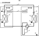
- FIG. 1 shows a hardware configuration of an air conditioner according to Embodiment 1.
- FIG. FIG. 2 is a block diagram showing the hardware configuration of the control board included in the outdoor unit according to Embodiment 1.
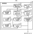
- FIG. 4 is a block diagram showing the functional configuration of the control board included in the outdoor unit according to Embodiment 1.
- FIG. 4 is a block diagram showing the configuration of a thermal characteristic model parameter update determination unit according to the first embodiment;
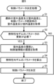
- FIG. 4 is a flowchart showing the procedure of control parameter determination processing executed by the control board provided in the outdoor unit according to the first embodiment;
- FIG. 4 is a diagram showing an output example of a simulation when determining control parameters according to the first embodiment; A diagram showing an example of information stored in the control parameter information storage unit according to the modification of the first embodiment A diagram showing the overall configuration of an air conditioning system in a modification of Embodiment 1
- FIG. 4 is a block diagram showing the hardware configuration of the control device in the modified example of Embodiment 1; A diagram showing a hardware configuration of an air conditioner according to Embodiment 2.
- FIG. 4 is a block diagram showing the configuration of a thermal characteristic model parameter update determination unit according to Embodiment 2;
- FIG. 10 is a flow chart showing the procedure of a thermal characteristic model parameter update necessity determination process executed by a thermal characteristic model parameter update determining unit according to the second embodiment;
- FIG. 11 is a diagram showing an example of a neural network in a modified example of the second embodiment;
- FIG. 10 is a block diagram showing the functional configuration of a control board included in the outdoor unit according to the third embodiment;
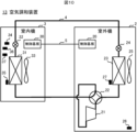
- FIG. 1 is a diagram showing the hardware configuration of an air conditioner 1 according to the present disclosure.
- the air conditioner 1 is an example of an air conditioner according to the present disclosure, and an example of an air conditioning system.
- the air conditioner 1 is a heat pump type air conditioner using a natural refrigerant such as HFC (hydrofluorocarbon) such as R32 or CO 2 as a refrigerant, and is a so-called room air conditioner.
- the air conditioner 1 includes an outdoor unit 2 installed outdoors and an indoor unit 3 installed indoors.
- the outdoor unit 2 and the indoor unit 3 are connected via a refrigerant pipe 4 for circulating refrigerant and a communication line 5 .
- the outdoor unit 2 includes a control board 20, a compressor 21, a four-way switching valve 22, an outdoor heat exchanger 23, an outdoor electromagnetic expansion valve 24, an outdoor fan 25, an outdoor temperature sensor 26, and an outdoor heat exchanger.
- a temperature sensor 27 is provided.
- the indoor unit 3 includes a control board 30 , an indoor heat exchanger 31 , an indoor electromagnetic expansion valve 32 , an indoor fan 33 , an indoor temperature sensor 34 and an indoor heat exchanger temperature sensor 35 .
- the compressor 21 , the four-way switching valve 22 , the outdoor heat exchanger 23 and the outdoor electromagnetic expansion valve 24 in the outdoor unit 2 , and the indoor electromagnetic expansion valve 32 and the indoor heat exchanger 31 in the indoor unit 3 are annularly connected by the refrigerant pipe 4 . connected to A refrigerant circuit is thereby configured.
- control board 20 is an example of a control device according to the present disclosure, and an example of air conditioning control means.
- the control board 20 includes a microcomputer 200, a communication interface 201, and an auxiliary storage device 202, as shown in FIG.
- the microcomputer 200 is a microcontroller that centrally controls the air conditioner 1 . Details of the functions of the control board 20 realized by the microcomputer 200 will be described later.
- the communication interface 201 is an interface for communicating with the control board 30 of the indoor unit 3 via the communication line 5 .
- the auxiliary storage device 202 is composed of a readable and writable non-volatile semiconductor memory such as EEPROM (Electrically Erasable Programmable Read-Only Memory) and flash memory.
- EEPROM Electrically Erasable Programmable Read-Only Memory
- Auxiliary storage device 202 stores various programs including programs for executing air conditioning control (hereinafter referred to as "air conditioning control programs"), and data used when these programs are executed.
- the control board 20 can acquire the air conditioning control program or an update program for updating the air conditioning control program from another device through communication.
- these programs are available on CD-ROM (Compact Disc Read Only Memory), DVD (Digital Versatile Disc), magneto-optical disc, USB (Universal Serial Bus) memory, HDD (Hard Disk Drive), SSD (Solid State Drive) , a memory card or other computer-readable recording medium for distribution.
- CD-ROM Compact Disc Read Only Memory
- DVD Digital Versatile Disc
- magneto-optical disc Digital Versatile Disc
- USB Universal Serial Bus
- HDD Hard Disk Drive
- SSD Solid State Drive
- the compressor 21 compresses the refrigerant. Specifically, the compressor 21 compresses a low-temperature, low-pressure refrigerant and discharges the high-pressure, high-temperature refrigerant to the four-way switching valve 22 .
- the compressor 21 has an inverter circuit that can change the number of revolutions according to the drive frequency.
- Compressor 21 is communicably connected to control board 20 via a communication line (not shown), and changes the drive frequency, ie, the number of revolutions, according to a command from control board 20 .
- the four-way switching valve 22 is a component for switching the circulation direction of the refrigerant.
- the state of the four-way switching valve 22 is as indicated by the solid line in FIG.
- the refrigerant circulates through the compressor 21 , the four-way switching valve 22 , the outdoor heat exchanger 23 , the outdoor electromagnetic expansion valve 24 , the indoor electromagnetic expansion valve 32 and the indoor heat exchanger 31 in this order.
- the state of the four-way switching valve 22 is as indicated by the dashed line in FIG.
- the refrigerant circulates through the compressor 21 , the four-way switching valve 22 , the indoor heat exchanger 31 , the indoor electromagnetic expansion valve 32 , the outdoor electromagnetic expansion valve 24 and the outdoor heat exchanger 23 in that order.
- the outdoor heat exchanger 23 exchanges heat between the outdoor air (that is, outside air) sucked by the outdoor fan 25 and the refrigerant.
- the outdoor heat exchanger 23 functions as a condenser when the operation mode of the air conditioner 1 is cooling, and functions as an evaporator when the operation mode of the air conditioner 1 is heating.
- the outdoor electromagnetic expansion valve 24 is installed between the outdoor heat exchanger 23 and the indoor electromagnetic expansion valve 32, and decompresses and expands the refrigerant flowing through the refrigerant pipe 4.
- the outdoor electromagnetic expansion valve 24 is, for example, an electromagnetic expansion valve that can adjust the opening of a throttle by a stepping motor (not shown).
- the outdoor electromagnetic expansion valve 24 is communicably connected to the control board 20 via a communication line (not shown), and adjusts the pressure of the refrigerant by changing the degree of opening according to a command from the control board 20 .
- the outdoor fan 25 is, for example, a propeller fan, sucks in outside air, and sends out the air heat-exchanged by the outdoor heat exchanger 23 to the outdoors.
- the outdoor fan 25 is communicably connected to the control board 20 via a communication line (not shown), and changes the number of revolutions according to a command from the control board 20 .
- the outdoor temperature sensor 26 measures the temperature of outdoor air sucked by the outdoor fan 25 .
- the outdoor temperature sensor 26 is communicably connected to the control board 20 via a communication line (not shown), and outputs a signal indicating the measured outdoor air temperature (hereinafter referred to as "outdoor temperature") to the control board 20.
- the outdoor heat exchanger temperature sensor 27 measures the temperature of the outdoor heat exchanger 23 .
- the outdoor heat exchanger temperature sensor 27 is communicably connected to the control board 20 via a communication line (not shown) and outputs a signal indicating the measured temperature of the outdoor heat exchanger 23 to the control board 20 .
- control board 30 includes a microcontroller for overall control of the indoor unit 3 in accordance with commands from the outdoor unit 2 and the control board 20 of the outdoor unit 2 via the communication line 5, although neither is shown.
- a communication interface including an interface for communication and an interface for wired or wireless communication with a remote controller (not shown), and an auxiliary storage device consisting of a readable and writable non-volatile semiconductor memory such as EEPROM and flash memory.
- the indoor heat exchanger 31 exchanges heat between the indoor air sucked by the indoor fan 33 and the refrigerant from the outdoor unit 2 .
- the indoor heat exchanger 31 functions as an evaporator during cooling operation, and functions as a condenser during heating operation.
- the indoor electromagnetic expansion valve 32 is installed between the indoor heat exchanger 31 and the outdoor electromagnetic expansion valve 24, and decompresses and expands the refrigerant flowing through the refrigerant pipe 4.
- the indoor electromagnetic expansion valve 32 is, for example, an electromagnetic expansion valve that can adjust the opening of a throttle by a stepping motor (not shown).
- the indoor electromagnetic expansion valve 32 is communicably connected to the control board 30 via a communication line (not shown), and adjusts the pressure of the refrigerant by changing the degree of opening according to a command from the control board 30 .
- the indoor fan 33 is, for example, a propeller fan, sucks indoor air, and sends out the air heat-exchanged by the indoor heat exchanger 31 indoors.
- the indoor fan 33 is communicably connected to the control board 30 via a communication line (not shown), and changes the number of revolutions according to a command from the control board 30 .
- the indoor temperature sensor 34 measures the temperature of the air sucked by the indoor fan 33 (that is, the indoor temperature).
- the room temperature sensor 34 is communicably connected to the control board 30 via a communication line (not shown) and outputs a signal indicating the measured room temperature to the control board 30 .
- the indoor heat exchanger temperature sensor 35 measures the temperature of the indoor heat exchanger 31 .
- the indoor heat exchanger temperature sensor 35 is communicably connected to the control board 30 via a communication line (not shown) and outputs a signal indicating the measured temperature of the indoor heat exchanger 31 to the control board 30 .
- the outdoor temperature sensor 26 of the outdoor unit 2 and the indoor temperature sensor 34 of the indoor unit 3 are examples of environment acquisition means according to the present disclosure.
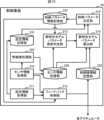
- the control board 20 functionally includes a sensor information acquisition unit 210, a setting information acquisition unit 211, a feedback control unit 212, a thermal characteristic model parameter update determination unit 213, and a thermal characteristic model A parameter calculator 214 and a control parameter determiner 215 are provided. These functional units are implemented by the microcomputer 200 executing the above-described air conditioning control program stored in the auxiliary storage device 202 .
- the sensor information acquisition unit 210 acquires sensor information.
- the sensor information includes the measurement result of the outdoor temperature sensor 26, the measurement result of the outdoor heat exchanger temperature sensor 27, the measurement result of the indoor temperature sensor 34, and the measurement result of the indoor heat exchanger temperature sensor 35.
- the sensor information acquisition unit 210 supplies the measurement result of the outdoor temperature sensor 26 and the measurement result of the indoor temperature sensor 34 among the acquired sensor information to the feedback control unit 212 . Further, the sensor information acquisition unit 210 sorts and stores the acquired sensor information in the sensor information storage unit 230 in chronological order.
- the sensor information storage unit 230 is a memory area provided by the auxiliary storage device 202 .
- the setting information acquisition unit 211 acquires setting information.
- the setting information is information related to the operation of the air conditioner 1 set by the user via a remote control, an operation panel, or the like (none of which is shown).
- the setting information acquisition unit 211 supplies the acquired setting information to the feedback control unit 212, and also sorts and stores the information in the setting information storage unit 231 in chronological order.
- the setting information storage unit 231 is a memory area provided by the auxiliary storage device 202 .
- the feedback control unit 212 is an example of feedback control means according to the present disclosure.
- the feedback control unit 212 controls each actuator (that is, the compressor 21, the outdoor electromagnetic expansion valve 24, the Feedback control is performed for the outdoor fan 25, the indoor electromagnetic expansion valve 32, and the indoor fan 33).
- a control parameter means a PID control parameter (Kp, Ti, Td) in the present embodiment.
- the feedback control unit 212 generates information indicating a control value for each actuator (hereinafter referred to as “control value information”), outputs the generated control value information to each actuator, and stores the control value information in the control value information storage unit 232 in time series. store them separately.
- the control value information storage unit 232 is a memory area provided by the auxiliary storage device 202 .
- the thermal characteristic model parameter update determination unit 213 is an example of update necessity determination means according to the present disclosure.
- the thermal characteristic model parameter update determination unit 213 updates the parameters of the thermal characteristic model regarding the thermal characteristics of the controlled object based on the difference between the outdoor environment and the indoor environment when the control parameters were last updated and the latest outdoor environment and indoor environment. Determine whether update is necessary.
- the thermal characteristic model parameter update determination unit 213 includes a latest data acquisition unit 216 , a control parameter update time data acquisition unit 217 , and a determination unit 218 .
- the latest data acquisition unit 216 acquires the latest outdoor temperature and indoor temperature from the sensor information storage unit 230 .
- the control parameter update time data acquisition unit 217 acquires the outdoor temperature and the indoor temperature at the time of control parameter update from the control parameter information storage unit 233 .
- the control parameter information storage unit 233 is an example of control parameter information storage means according to the present disclosure, and is a memory area provided by the auxiliary storage device 202 .
- the control parameter information storage unit 233 stores the most recently determined (that is, updated) control parameter and the outdoor temperature and indoor temperature at the time of the update.
- the determination unit 218 determines whether or not the parameters of the thermal characteristic model need to be updated based on the latest outdoor temperature, indoor temperature, and the outdoor temperature and indoor temperature at the time of updating the control parameters. Determine whether parameters need to be calculated.
- the thermal characteristic model parameter calculation unit 214 is an example of model parameter calculation means according to the present disclosure.
- the thermal characteristic model parameter calculation unit 214 calculates the room temperature history acquired from the sensor information storage unit 230 and the control Based on the control value information history of each actuator acquired from the value information storage unit 232, parameters of the thermal characteristic model are calculated.
- the thermal characteristic model parameter calculation unit 214 uses the calculated parameters of the thermal characteristic model, the outdoor temperature and the indoor temperature at the time of calculating the parameters of the thermal characteristic model, the indoor temperature at the start of operation, and the control value information of each actuator as control parameters. It is supplied to the determination unit 215 .
- the control parameter determination unit 215 is an example of control parameter determination means according to the present disclosure.
- the control parameter determining unit 215 uses the parameters of the thermal characteristic model supplied from the thermal characteristic model parameter calculating unit 214, the indoor temperature at the start of operation and the control value information of each actuator, and the latest information obtained from the setting information storage unit 231.
- a control parameter for each actuator is determined based on the set temperature.
- the control parameter determining unit 215 stores the determined control parameters and the outdoor temperature and the indoor temperature at the time of determining the control parameters (that is, at the time of updating the control parameters) in the control parameter information storage unit 233 . If the control parameters have never been updated by the control parameter determination unit 215, the control board 20 operates the feedback control unit 212 with the initially set control parameters.
- the control parameter information storage unit 233 stores information indicating the control parameters of each actuator and information indicating the outdoor temperature and indoor temperature when the control parameters were determined.
- the control parameter information storage unit 233 stores the control parameters for each actuator separately for a comfort-oriented mode that brings the indoor temperature to the set temperature as soon as possible and an energy-saving mode that reduces the amount of power consumption as much as possible.
- the feedback control unit 212 acquires the control parameter of each actuator from the control parameter information storage unit 233 at a predetermined timing such as when the power of the air conditioner 1 is turned on again. At this time, the user selects either the comfort-oriented mode or the energy-saving mode, and the user's selection result is notified to the feedback control unit 212 via the setting information acquisition unit 211 . If the user has not selected a mode, one of the modes is notified to feedback control section 212 as an initial setting. The feedback control unit 212 acquires the control parameter of each actuator corresponding to the mode selected by the user or the mode initially set from the control parameter information storage unit 233 .
- FIG. 5 is a flowchart showing the procedure of control parameter determination processing executed by the control board 20 of the outdoor unit 2.
- the control parameter determination process is executed, for example, when the user performs a stop operation via the remote controller or the operation panel, or when the set temperature is changed.
- Step S1 The thermal characteristic model parameter update determination unit 213 of the control board 20 acquires the latest outdoor temperature and indoor temperature from the sensor information storage unit 230, and acquires the outdoor temperature and indoor temperature at the time of control parameter update from the control parameter information storage unit 233. do. After that, the process of the control board 20 transitions to step S2.
- Step S2 The thermal characteristic model parameter update determination unit 213 determines whether or not it is necessary to update the parameters of the thermal characteristic model. Specifically, the thermal characteristic model parameter update determination unit 213 compares the acquired latest (that is, this time) outdoor temperature and indoor temperature with the outdoor temperature and indoor temperature at the time of the previous control parameter update, When at least one of the difference between the current outdoor temperature and the previous update outdoor temperature and the difference between the current indoor temperature and the previous update exceeds a predetermined threshold value determines that the indoor/outdoor thermal characteristics have changed since the previous update, and determines that the parameters of the thermal characteristics model need to be updated. If it is determined that the parameters of the thermal characteristic model need to be updated (step S2; YES), the processing of the control board 20 transitions to step S3.
- the thermal characteristic model parameter update determination unit 213 determines that the indoor and outdoor thermal characteristics have not changed, determines that there is no need to update the parameters of the thermal characteristic model (step S2; NO), and ends the control parameter determination process. do.
- Step S3 The thermal characteristic model parameter calculation unit 214 acquires the history of room temperature from the sensor information storage unit 230 and acquires the history of control value information of each actuator from the control value information storage unit 232 . After that, the processing of the control board 20 transitions to step S4.
- the thermal characteristic model parameter calculator 214 calculates parameters of the thermal characteristic model. Whether it is a continuous-time system or a discrete-time system, a first-order lag system or a higher-order lag system, a single-input single-output system, or a multiple-input multiple-output system depends on the design specifications of the air conditioner 1, the object to be controlled, and the linearization method. depends on In the present embodiment, a discrete-time system, a one-input one-output system, and a first-order lag system considering dead time will be described.
- t s is the recording cycle of the control value of each actuator and the room temperature
- (t) is a variable representing time series
- (t+t s ) represents the time following (t) in time series.
- K is the system gain
- T is the time constant
- L is the dead time, which are the parameters of the thermal characteristic model.
- the thermal characteristic model parameter calculation unit 214 receives Qm(t) calculated from the control value x m (t) of each actuator acquired from the control value information storage unit 232 and calculates the time response of Tc(t). As for the dead time L, if the accuracy is higher than the recording cycle, it is rounded down or rounded up as necessary.
- the thermal characteristic model parameter calculation unit 214 calculates the error between the calculated Tc(t) and the room temperature Tm(t) acquired from the sensor information storage unit 230.
- the mean square error MSE is used as the error evaluation function to be minimized.
- the thermal characteristic model parameter calculator 214 calculates the time response of the thermal characteristic model by changing the system gain K, the time constant T, and the dead time L, and determines the system gain K and the time constant that minimize the mean square error MSE A combination of T and dead time L is calculated. As described above, the thermal characteristic model parameter calculator 214 calculates the parameters of the thermal characteristic model. After that, the processing of the control board 20 transitions to step S5.
- Step S5 The control parameter determination unit 215 is based on the parameters of the thermal characteristic model calculated in step S4, the room temperature at the start of operation, the control value information of each actuator, and the latest setting temperature acquired from the setting information storage unit 231. to determine the control parameters.
- a feedback control simulator (not shown) is incorporated in the control parameter determining unit 215, and according to a predetermined feedback control rule, the control value xc (t) of each actuator, the amount of heat supplied to the room Qc(t), the room temperature Tc(t) is calculated.
- the amount of heat Qc(t) supplied to the room is calculated as a function f( xc (t)) of the control value xc (t) of each actuator.
- a constraint condition may be given to the control value x c (t) indicating the frequency of the compressor 21 so that it does not fall below the dew point.
- the amount of electric power E is calculated based on the arrival time tr when the indoor temperature Tc(t) reaches the set temperature, the maximum overshoot amount ⁇ Tmax, and the control value xc (t) of each actuator.
- the integrated time for calculating the electric energy E is, for example, the integrated time from the time of startup to the time tr when the set temperature is reached, or the time t from the time of startup to the time when the set temperature falls within the specified error range ⁇ Te.
- the integrated time up to e and the integrated time up to a predesignated time ta from the time of startup are used.
- the control parameter determination unit 215 changes the combination of control parameters to calculate the time response of the thermal characteristic model, and calculates the combination of control parameters that minimizes the arrival time tr and the electric energy E, respectively.
- a more suitable operating condition can be selected by giving constraints on the maximum overshoot amount ⁇ Tmax and the arrival time t r . can do.
- the control parameter determination unit 215 stores the calculated control parameter of each actuator in the control parameter information storage unit 233 together with the outdoor temperature and the indoor temperature. After that, the control board 20 ends the control parameter determination process.
- the feedback control unit 212 updates the control parameter of each actuator to the value read from the control parameter information storage unit 233 at a predetermined timing such as when the power of the air conditioner 1 is turned on again. At this time, as described above, the user selects either the comfort-oriented mode or the energy-saving mode, and the feedback control unit 212 is notified of the selection result via the setting information acquisition unit 211 .
- the feedback control unit 212 determines from the control parameter information storage unit 233 that the control parameter of each actuator corresponding to the comfort-oriented mode, that is, the arrival time tr becomes the minimum. Read the control parameters of each actuator. In addition, when the energy saving mode is selected by the user, the feedback control unit 212 selects the control parameter of each actuator corresponding to the energy saving mode from the control parameter information storage unit 233, that is, the control parameter of each actuator that minimizes the electric energy E. Read control parameters.
- the air conditioning apparatus 1 according to Embodiment 1 can achieve air conditioning that follows changes in the indoor and outdoor environments, so it is possible to prevent the comfort of the user from being impaired.
- control board 20 of the outdoor unit 2 has at least one of the difference between the latest outdoor temperature and the outdoor temperature at the previous update and the difference between the latest indoor temperature and the indoor temperature at the previous update in advance.
- the control board 20 calculates the parameters of the thermal characteristic model and determines the control parameters. Therefore, the number of times the control parameters are updated can be reduced, the calculation load can be suppressed, and the power consumption of the air conditioner 1 can be suppressed.
- the thermal characteristic model parameter update determination unit 213 may have a plurality of thresholds for determining whether updating is necessary, and the determination conditions may be subdivided.
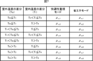
- the control parameter information storage unit 233 stores control parameters for each determined condition, as shown in FIG.
- two thresholds, a first threshold T1 and a second threshold T2 are used as thresholds for the difference in outdoor temperature for determining whether the update is necessary.
- Two thresholds, a third threshold T 3 and a fourth threshold T 4 are used.
- the difference between the latest outdoor temperature and the previous updated outdoor temperature is less than or equal to the first threshold value T1
- the difference between the latest indoor temperature and the previous updated indoor temperature is If the third threshold value T3 or less, the thermal characteristic model parameter update determination unit 213 determines that the parameters of the thermal characteristic model do not need to be updated. Otherwise, that is, the difference between the latest outdoor temperature and the last updated outdoor temperature is greater than the first threshold value T1 , or the difference between the latest indoor temperature and the last updated indoor temperature is If it is greater than the third threshold value T3 , the thermal characteristic model parameter update determination unit 213 determines that the parameters of the thermal characteristic model need to be updated.
- the difference between the latest outdoor temperature and the outdoor temperature at the previous update is less than or equal to the first threshold T1
- the difference between the latest indoor temperature and the indoor temperature at the previous update is the fourth threshold.
- the control parameter ⁇ c,1 for the comfort-oriented mode and the control parameter ⁇ e,1 for the energy-saving mode are associated.
- ⁇ indicates a control constant
- subscripts c and e indicate a comfort-oriented mode and an energy-saving mode, respectively
- subscript 1 indicates the first case.
- the thresholds for the outdoor temperature and the indoor temperature for determining whether the update is necessary are not limited to two, and may be three or more.
- the feedback control unit 212 determines the control parameter in the control parameter determination process shown in FIG. After being stored in the storage unit 233, based on the difference between the current outdoor temperature and the outdoor temperature at the time of the previous update, and the difference between the current indoor temperature and the indoor temperature at the time of the previous update, a more suitable control parameter is set as the control parameter information. You may read from the memory
- the control parameter when the control parameter is determined due to the user's stop operation, the temperature difference when the operation of the air conditioner 1 is stopped (the difference between the outdoor temperature at that time and the outdoor temperature at the time of the previous update, and the If the difference between the room temperature at the time and the room temperature at the time of the previous update) and the temperature difference at the next start-up operation are different, using the control parameters updated at the time of stop, that is, the control parameters updated most recently, Comfort may be compromised. Therefore, by making it possible to select more suitable control parameters based on the respective temperature differences during start-up operation, it is possible to suppress the decrease in comfort.
- FIG. 8 is a diagram showing the overall configuration of the air conditioning system 10 in this modification.
- the air conditioning system 10 is an example of an air conditioning system according to the present disclosure. As shown in FIG. 8 , the air conditioning system 10 includes an air conditioning device 1 ′ and a control device 11 .
- the air conditioner 1 ′ and the control device 11 are communicably connected to each other via a communication line 12 .
- the configuration may be such that communication between the air conditioner 1′ and the control device 11 is performed wirelessly.
- the air conditioner 1' is an example of the air conditioner according to the present disclosure.
- the hardware configuration of the air conditioner 1' is the same as that of the air conditioner 1 (see FIG. 1).
- the control board 20 of the outdoor unit 2 included in the air conditioner 1' does not include the functional units shown in FIG. 3 and does not execute the control parameter determination process shown in FIG.
- the control device 11 is an example of a control device according to the present disclosure, and an example of air conditioning control means.
- the control device 11 is a computer that controls each actuator of the air conditioner 1', that is, the compressor 21, the outdoor electromagnetic expansion valve 24, the outdoor fan 25, the indoor electromagnetic expansion valve 32, and the indoor fan 33, and is shown in FIG.
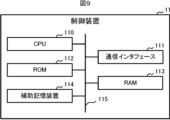
- the hardware configuration includes a CPU (Central Processing Unit) 110, a communication interface 111, a ROM (Read Only Memory) 112, a RAM (Random Access Memory) 113, and an auxiliary storage device 114. These components are interconnected via bus 115 .
- CPU Central Processing Unit
- ROM Read Only Memory
- RAM Random Access Memory
- the CPU 110 comprehensively controls the control device 11 .
- the communication interface 111 is hardware for communicating with the air conditioner 1 ′ via the communication line 12 . Note that the communication interface 111 may be hardware for wirelessly communicating with the air conditioner 1'.
- the ROM 112 stores multiple pieces of firmware and data used when executing these pieces of firmware.
- a RAM 113 is used as a work area for the CPU 110 .
- the auxiliary storage device 114 is composed of a readable/writable non-volatile semiconductor memory, HDD, or the like.
- the readable/writable non-volatile semiconductor memory is, for example, EEPROM, flash memory, or the like.
- Auxiliary storage device 114 stores various programs including the above-described air conditioning control program, and data used when these programs are executed.
- the control device 11 can acquire the air conditioning control program or an update program for updating the air conditioning control program from another device through communication. These programs can also be stored and distributed in computer-readable recording media such as CD-ROMs, DVDs, magneto-optical discs, USB memories, HDDs, SSDs, and memory cards. When such a recording medium is directly or indirectly attached to itself, the control device 11 may read and acquire the air conditioning control program or update program from the recording medium.
- the control device 11 includes the functional units shown in FIG. 3, and executes the control parameter determination process shown in FIG.
- the functional units included in the control device 11 are implemented by the CPU 110 executing an air conditioning control program stored in the auxiliary storage device 114 .
- At least a part of the sensor information storage unit 230, the setting information storage unit 231, the control value information storage unit 232, and the control parameter information storage unit 233 included in the control board 20 in the above embodiment can be connected to the air conditioner 1, the Internet, or the like. may be provided in a server such as a cloud server that is communicatively connected via a network. By doing so, the capacity of the auxiliary storage device 202 mounted on the control board 20 can be reduced. Further, even if the server includes at least part of the thermal characteristic model parameter update determination unit 213, the thermal characteristic model parameter calculation unit 214, and the control parameter determination unit 215 included in the control board 20 in the above embodiment, good.
- Modification 4 All or part of the functional units (see FIG. 3) of the control board 20 may be realized by dedicated hardware.
- Dedicated hardware is, for example, a single circuit, multiple circuits, a programmed processor, an ASIC (Application Specific Integrated Circuit), an FPGA (Field-Programmable Gate Array), or a combination thereof.
- FIG. 10 is a diagram showing the hardware configuration of the air conditioner 13 according to the second embodiment.
- the air conditioner 13 is an example of an air conditioner according to the present disclosure.
- the indoor unit 3 includes a control board 30, an indoor heat exchanger 31, an indoor electromagnetic expansion valve 32, an indoor fan 33, an indoor temperature sensor 34, and an indoor heat exchanger temperature sensor. 35, an indoor humidity sensor 36 for measuring indoor humidity and an infrared sensor 37 are added.
- the parameters of the thermal characteristic model are calculated based on the outdoor temperature measured by the outdoor temperature sensor 26 of the outdoor unit 2 and the indoor temperature measured by the indoor temperature sensor 34 of the indoor unit 3. It was determined no. In the second embodiment, it is determined whether or not to calculate the parameters of the thermal characteristic model based on the information acquired by the indoor humidity sensor 36 and the infrared sensor 37 of the indoor unit 3 in addition to the outdoor temperature and the indoor temperature. .
- the infrared sensor 37 detects the temperature of the indoor space by scanning infrared rays.
- the infrared sensor 37 is composed of, for example, thermopiles arranged vertically, and scanned horizontally at regular intervals.
- a plurality of vertical thermal images (that is, one-dimensional thermal images) acquired by the infrared sensor 37 are created by scanning the infrared sensor 37 in the horizontal direction, and a plurality of vertical thermal images are synthesized after scanning.
- a two-dimensional thermal image is created in the room.
- the sensor information acquisition unit 210 of the present embodiment also acquires the measurement result of the indoor humidity sensor 36 and the thermal image created by the infrared sensor 37 as sensor information, and stores them in the sensor information storage unit 230 .
- FIG. 11 is a diagram showing the configuration of the thermal characteristic model parameter update determination unit 213 included in the control board 20 of the air conditioner 13 according to the second embodiment.
- the thermal characteristic model parameter update determination unit 213 in the second embodiment includes a latest data acquisition unit 216, a control parameter update time data acquisition unit 217, an inference unit 219, and a determination unit 218. .
- the latest data acquisition unit 216 acquires the latest outdoor temperature, indoor temperature, indoor humidity, and thermal image from the sensor information storage unit 230 .
- the control parameter update time data acquisition unit 217 acquires the estimated heat load amount at the time of control parameter update from the control parameter information storage unit 233 .
- the inference unit 219 uses a learned model for inferring the estimated heat load from the outdoor temperature, indoor temperature, indoor humidity, and thermal image, which is stored in the learned model storage unit 234 and generated in advance by learning. to infer the estimated heat load. That is, the inference unit 219 inputs the acquired outdoor temperature, indoor temperature, indoor humidity, and thermal image to the learned model, thereby acquiring an estimated heat load amount inferred from these input data.
- the trained model storage unit 234 is an example of trained model storage means according to the present disclosure, and is a memory area provided by the auxiliary storage device 202 .
- the determination unit 218 calculates the parameters of the thermal characteristic model based on the estimated heat load amount at the previous update acquired by the control parameter update time data acquisition unit 217 and the estimated heat load amount inferred by the inference unit 219. determine whether it is necessary to Specifically, when the difference between the latest estimated heat load amount and the estimated heat load amount at the time of the previous update exceeds a predetermined threshold value, the determining unit 218 It is determined that the characteristics have changed and that the parameters of the thermal characteristic model need to be updated.
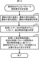
- FIG. 12 is a flow chart showing the procedure of the thermal characteristic model parameter update necessity determination process executed by the thermal characteristic model parameter update determination unit 213 according to the second embodiment.
- Step S10 The thermal characteristic model parameter update determination unit 213 acquires the latest outdoor temperature, indoor temperature, indoor humidity, and thermal image from the sensor information storage unit 230 . After that, the process of the thermal characteristic model parameter update determination unit 213 transitions to step S11.
- Step S11 The thermal characteristic model parameter update determination unit 213 inputs the acquired outdoor temperature, indoor temperature, indoor humidity, and thermal image to the learned model stored in the learned model storage unit 234, and acquires the estimated heat load amount. . After that, the processing of the thermal characteristic model parameter update determination unit 213 transitions to step S12.
- Step S12 The thermal characteristic model parameter update determination unit 213 calculates parameters of the thermal characteristic model based on the obtained estimated heat load amount and the estimated heat load amount at the time of the previous control parameter update obtained from the control parameter information storage unit 233. It is determined whether it is necessary to update the parameters of the thermal characteristic model. In addition, when the thermal characteristic model parameter update determination unit 213 determines that the parameter of the thermal characteristic model needs to be updated, the estimated heat load amount acquired this time is controlled by the control parameter determination unit 215 after the control parameter is determined. It is saved in the parameter information storage unit 233 .
- the outdoor temperature, the indoor temperature, the indoor humidity, and the thermal image are input to the learned model to acquire the estimated heat load, and the acquired estimated heat load and the estimated heat load amount at the time of the previous update, it is determined whether or not the control parameters need to be updated.
- the indoor humidity as an input, it is possible to consider the latent heat load required to reduce the indoor humidity in addition to the sensible heat load required to lower the indoor temperature.
- thermal images it is possible to estimate information such as human body heat load, equipment heat load, ventilation heat load, indoor wall temperature, and room layout.
- human body heat load it is possible to take into consideration the heat load caused by the heat generated by the person, and it is possible to make a determination considering the heat load that changes depending on the presence or absence of people, the number of people, the size, and the like.
- equipment heat load it is possible to make a determination that takes into consideration the heat load caused by the lighting equipment and the electronic equipment generating heat.
- the ventilation heat load it is possible to make judgments that take into account the heat load that occurs when air is exchanged between the indoor and outdoor areas when opening windows or doors for ventilation.
- the room wall temperature it is possible to make a determination that takes into consideration the insulation performance of the walls, floor, and ceiling of the room.
- the room layout it is possible to make a determination considering the volume of the room. In this way, by using a thermal image as an input, it is possible to expect the effect of being able to more accurately determine changes in the indoor environment between now and when the control parameters are updated.
- Modification 1 In the above embodiment, a configuration in which a pre-generated learned model is stored in the control board 20 has been described. You may make it provide a part.
- the model generator generates a trained model for inferring the estimated amount of heat load, based on learning data acquired by communication from a plurality of other air conditioners 13 .
- a plurality of other air conditioners 13 may be installed in the same building as the air conditioner 13 concerned, or may be installed in a different building.
- the model generator learns the estimated heat load corresponding to the input data (that is, outdoor temperature, indoor temperature, indoor humidity, and thermal image), for example, by supervised learning using a neural network.
- a neural network is composed of an input layer to which input data is input, an output layer to which output data is output, and at least one intermediate layer (also referred to as a hidden layer). Each layer is composed of a plurality of nodes. be.
- the number of nodes in the input layer corresponds to the number of input data, and the number of nodes in the output layer corresponds to the number of output data.
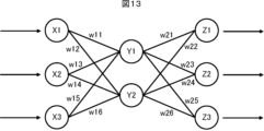
- FIG. 13 shows an example of a three-layer neural network. In the example shown in FIG. 13, the input layer consists of nodes X1 to X3, the intermediate layer consists of nodes Y1 to Y2, and the output layer consists of nodes Z1 to Z3.
- the model generator uses the data set included in the learning data as teacher data, and outputs from the output layer when input data (that is, outdoor temperature, indoor temperature, indoor humidity, and thermal image) is input to the input layer
- input data that is, outdoor temperature, indoor temperature, indoor humidity, and thermal image
- the weight of the connection between each layer is performed by adjusting the weights w21 to w26) between layers to generate a trained model.
- the learning algorithm used in the model generation unit it is also possible to adopt deep learning (Deep Learning) that learns to extract the feature amount itself, and other known methods such as genetic programming, functional logic programming, Machine learning may be performed according to support vector machines and the like.
- Deep learning Deep Learning
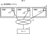
- FIG. 14 is a diagram showing the overall configuration of the air conditioning system 14 in this modified example.
- the air conditioning system 14 is an example of an air conditioning system according to the present disclosure.
- air conditioners 13′A to 13′C are installed in a plurality of rooms A to C in the same building B, respectively, and the server 15 controls each of the air conditioners 13′A to 13′C. is controlled.
- the air conditioners 13'A to 13'C and the server 15 are communicably connected via a network N such as the Internet.
- the air conditioners 13'A to 13'C are examples of air conditioners according to the present disclosure.
- the hardware configuration of the air conditioners 13'A to 13'C is the same as that of the air conditioner 1 (see FIG. 1).
- the control board 20 of the outdoor unit 2 included in the air conditioners 13'A to 13'C does not include the functional units shown in FIGS. 3 and 11, and does not execute the processes shown in FIGS.
- the server 15 is an example of a control device according to the present disclosure, and an example of air conditioning control means.
- the server 15 is a computer that controls the actuators of the air conditioners 13'A to 13'C, that is, the compressor 21, the outdoor electromagnetic expansion valve 24, the outdoor fan 25, the indoor electromagnetic expansion valve 32, and the indoor fan 33.
- the hardware configuration of the server 15 is the same as that of the control device 11 in Modification 2 of Embodiment 1 (see FIG. 9).
- the server 15 includes the functional units shown in FIGS. 3 and 11, and executes the control parameter determination process shown in FIG. 5 and the thermal characteristic model parameter update necessity determination process shown in FIG.
- the air conditioners 13′A to 13′C By connecting the air conditioners 13′A to 13′C via the server 15 in this way, for example, it becomes possible to perform air conditioning that takes into consideration the room temperature of adjacent rooms, and when predicting the wall temperature, It becomes possible to improve the accuracy. Specifically, if the air conditioner 13'B of the room B adjacent to the room A operates and the room temperature of the room B approaches the set temperature, the wall of the room A adjacent to the room B is close to the set temperature of the air conditioner 13'B. Also, if the air conditioner 13'B is not in operation, the temperature of the wall adjacent to the room B among the walls of the room A is close to the outside air temperature.
- the server 15 holds the floor plan information of the building B in advance. As a result, it is possible to grasp in advance the difference in the amount of heat load caused by the difference in the layout of the room, and it is possible to improve the estimation accuracy of the amount of heat load.
- the floor plan information of building B includes information indicating the layout of each room in building B, such as whether it is a corner room or a middle room, and whether it is on the top floor or not. For example, from information such as whether a room is a corner room or a middle room, or whether it is on the top floor or not, it is possible to know in advance which side of the room the wall is in contact with the outside air. can be enhanced.
- the information stored in the control parameter information storage unit 233 may be shared for rooms determined to have the same or similar room layout information. By sharing the stored information, the update frequency of the control parameters increases as compared with the case where only one air conditioner 13' is operated. As a result, it is possible to more quickly prevent the comfort of the user from being impaired.
- a thermal image processing unit 220 is added as a functional configuration to the control board 20 included in the outdoor unit 2 according to the third embodiment.
- the sensor information acquisition unit 210 of the present embodiment outputs the thermal image acquired from the infrared sensor 37 (see FIG. 10) to the thermal image processing unit 220, and outputs other sensor information to the thermal image processing unit 220.
- the thermal image processing unit 220 is an example of thermal image processing means according to the present disclosure.
- the thermal image processing unit 220 estimates human body heat load, equipment heat load, ventilation heat load, indoor wall temperature, and room layout from the thermal image input from the sensor information acquisition unit 210 .
- the estimated human body heat load, equipment heat load, ventilation heat load, room wall temperature, and room layout are stored in the sensor information storage unit 230 .
- the sensor information storage unit 230 stores the sensor information input from the sensor information acquisition unit 210, and the human body heat load, equipment heat load, ventilation heat load, indoor wall temperature, and room layout input from the thermal image processing unit 220. are associated with each other and stored as a sensor information history.
- the thermal characteristic model parameter update determination unit 213 of the present embodiment has the same configuration as the thermal characteristic model parameter update determination unit 213 of the second embodiment (see FIG. 11). However, in the present embodiment, the latest data acquisition unit 216 obtains the latest outdoor temperature, indoor temperature, indoor humidity, human heat load, equipment heat load, ventilation heat load, indoor wall temperature, and indoor temperature from the sensor information storage unit 230 . Get a floor plan for
- the inference unit 219 of the present embodiment stores the outdoor temperature, indoor temperature, indoor humidity, human body heat load, equipment heat load, ventilation heat load, which are generated in advance by learning, which are stored in the learned model storage unit 234.
- the estimated heat load is inferred using a trained model for inferring the estimated heat load from the room wall temperature and room layout. That is, the inference unit 219 of the present embodiment adds the acquired outdoor temperature, indoor temperature, indoor humidity, human heat load, equipment heat load, ventilation heat load, indoor wall temperature, and room layout to the learned model. By inputting, it is possible to obtain the estimated heat load amount inferred from these input data.
- the control board 20 in Embodiment 3 estimates the human body heat load, equipment heat load, ventilation heat load, indoor wall temperature, and room layout from the thermal image obtained by the infrared sensor 37. and store it in the sensor information storage unit 230 .
- Information on values such as human body heat load, equipment heat load, ventilation heat load, room wall temperature, and room layout has a smaller data size than a thermal image. Therefore, the amount of data to be stored in the sensor information storage unit 230 can be reduced.
- the thermal image processing unit 220 estimates at least one of human body heat load, equipment heat load, ventilation heat load, indoor wall temperature, and room layout from the indoor thermal image, and the learned model is for inferring an estimated heat load from input data including outdoor temperature, indoor temperature, indoor humidity, and at least one of human heat load, equipment heat load, ventilation heat load, indoor wall temperature, and room layout; can be anything.
- Modification 1 All or part of the functional units of the control board 20 (see FIG. 15) may be realized by dedicated hardware.
- Dedicated hardware may be, for example, single circuits, multiple circuits, programmed processors, ASICs, FPGAs, or combinations thereof.
Landscapes
- Engineering & Computer Science (AREA)
- Chemical & Material Sciences (AREA)
- Combustion & Propulsion (AREA)
- Mechanical Engineering (AREA)
- General Engineering & Computer Science (AREA)
- Signal Processing (AREA)
- Physics & Mathematics (AREA)
- Fuzzy Systems (AREA)
- Mathematical Physics (AREA)
- Air Conditioning Control Device (AREA)
Abstract
空気調和装置の制御基板(20)は、制御パラメータに基づいて室内温度が設定温度となるように空気調和装置を制御するフィードバック制御部(212)と、制御対象の熱特性に関する熱特性モデルのパラメータを算出する熱特性モデルパラメータ算出部(214)と、熱特性モデルのパラメータに基づいて制御パラメータを決定する制御パラメータ決定部(215)と、制御パラメータを前回更新した際の室外環境及び室内環境と最新の室外環境及び室内環境との相違に基づいて、熱特性モデルのパラメータを更新する必要があるか否かを判定する熱特性モデルパラメータ更新判定部(213)とを備える。熱特性モデルパラメータ算出部(214)は、熱特性モデルパラメータ更新判定部(213)によって熱特性モデルのパラメータを更新する必要があると判定された場合に熱特性モデルのパラメータを算出する。これにより、ユーザの快適性を損なわずに電力量を抑制する。
Description
本開示は、制御装置、空気調和システム、空気調和装置の制御方法、プログラム、学習済モデル及び学習済モデルの生成方法に関する。
室内温度がユーザにより入力された設定温度になるように室内の空気調和を行う空気調和装置において、空気調和の対象となる室内の熱環境の大きな変化に対して好適に制御されるようにするための技術が知られている(例えば、特許文献1)。
特許文献1に記載の空気調和機では、オンラインシステム同定器によって、室内機が配置される利用部の熱容量並びに熱通過係数を少なくとも要因とする利用部熱環境の状態、及び、圧縮機の駆動周波数と当該空気調和機の能力の関係を表すパラメータが、複数の所定の観測量を元に時々刻々同定される。
特許文献1に記載の空気調和機のように、運転中にオンラインシステム同定器が時々刻々と上記のパラメータを同定する手法では、計算負荷が大きく、電力量が増大してしまうという問題がある。
本開示は、上記問題を解決するためになされたものであり、ユーザの快適性を損なわずに、計算負荷を抑えることで電力量を抑制することが可能な制御装置、空気調和システム、空気調和装置の制御方法、プログラム、学習済モデル及び学習済モデルの生成方法を提供することを目的とする。
上記目的を達成するため、本開示に係る制御装置は、
制御パラメータに基づいて室内温度が設定温度となるように空気調和装置を制御するフィードバック制御手段と、
制御対象の熱特性に関する熱特性モデルのパラメータを算出するモデルパラメータ算出手段と、
前記熱特性モデルのパラメータに基づいて制御パラメータを決定する制御パラメータ決定手段と、
制御パラメータを前回更新した際の室外環境及び室内環境と最新の室外環境及び室内環境との相違に基づいて、前記熱特性モデルのパラメータを更新する必要があるか否かを判定する更新要否判定手段と、を備え、
前記モデルパラメータ算出手段は、前記更新要否判定手段によって前記熱特性モデルのパラメータを更新する必要があると判定された場合に前記熱特性モデルのパラメータを算出する。
制御パラメータに基づいて室内温度が設定温度となるように空気調和装置を制御するフィードバック制御手段と、
制御対象の熱特性に関する熱特性モデルのパラメータを算出するモデルパラメータ算出手段と、
前記熱特性モデルのパラメータに基づいて制御パラメータを決定する制御パラメータ決定手段と、
制御パラメータを前回更新した際の室外環境及び室内環境と最新の室外環境及び室内環境との相違に基づいて、前記熱特性モデルのパラメータを更新する必要があるか否かを判定する更新要否判定手段と、を備え、
前記モデルパラメータ算出手段は、前記更新要否判定手段によって前記熱特性モデルのパラメータを更新する必要があると判定された場合に前記熱特性モデルのパラメータを算出する。
本開示によれば、ユーザの快適性を損なわずに電力量を抑制することが可能となる。
以下、本開示の実施の形態について図面を参照して詳細に説明する。
(実施の形態1)
図1は、本開示に係る空気調和装置1のハードウェア構成を示す図である。空気調和装置1は、本開示に係る空気調和装置の一例であり、空気調和システムの一例である。空気調和装置1は、R32等のHFC(ハイドロフルオロカーボン)、CO2等の自然冷媒を冷媒として用いたヒートポンプ式の空気調和装置であり、いわゆるルームエアコンである。図1に示すように、空気調和装置1は、室外に設置される室外機2と、室内に設置される室内機3とを備える。室外機2と室内機3は、冷媒を循環させるための冷媒配管4と、通信線5とを介して接続される。
図1は、本開示に係る空気調和装置1のハードウェア構成を示す図である。空気調和装置1は、本開示に係る空気調和装置の一例であり、空気調和システムの一例である。空気調和装置1は、R32等のHFC(ハイドロフルオロカーボン)、CO2等の自然冷媒を冷媒として用いたヒートポンプ式の空気調和装置であり、いわゆるルームエアコンである。図1に示すように、空気調和装置1は、室外に設置される室外機2と、室内に設置される室内機3とを備える。室外機2と室内機3は、冷媒を循環させるための冷媒配管4と、通信線5とを介して接続される。
室外機2は、制御基板20と、圧縮機21と、四方切換弁22と、室外熱交換器23と、室外電磁膨張弁24と、室外ファン25と、室外温度センサ26と、室外熱交換器温度センサ27と備える。室内機3は、制御基板30と、室内熱交換器31と、室内電磁膨張弁32と、室内ファン33と、室内温度センサ34と、室内熱交換器温度センサ35とを備える。室外機2における、圧縮機21、四方切換弁22、室外熱交換器23及び室外電磁膨張弁24と、室内機3における室内電磁膨張弁32及び室内熱交換器31とは、冷媒配管4により環状に接続される。これにより、冷媒回路が構成される。
室外機2において、制御基板20は、本開示に係る制御装置の一例であり、空調制御手段の一例である。制御基板20は、図2に示すように、マイコン200と、通信インタフェース201と、補助記憶装置202とを備える。マイコン200は、空気調和装置1を統括的に制御するマイクロコントローラである。マイコン200によって実現される制御基板20の機能の詳細については後述する。通信インタフェース201は、室内機3の制御基板30と通信線5を介して通信するためのインタフェースである。
補助記憶装置202は、例えば、EEPROM(Electrically Erasable Programmable Read-Only Memory)、フラッシュメモリ等の読み書き可能な不揮発性の半導体メモリで構成される。補助記憶装置202には、空調制御を実行するためのプログラム(以下「空調制御プログラム」という。)を含む各種のプログラムと、これらのプログラムの実行時に使用されるデータとが記憶される。
制御基板20は、上記の空調制御プログラム又は空調制御プログラムを更新するための更新プログラムを他の装置から通信により取得することが可能である。また、これらのプログラムは、CD-ROM(Compact Disc Read Only Memory)、DVD(Digital Versatile Disc)、光磁気ディスク、USB(Universal Serial Bus)メモリ、HDD(Hard Disk Drive)、SSD(Solid State Drive)、メモリカード等のコンピュータ読み取り可能な記録媒体に格納して配布することも可能である。制御基板20は、そのような記録媒体が室外機2に直接又は間接的に装着された場合、当該記録媒体から空調制御プログラム又は更新プログラムを読み出して取得してもよい。
図1に戻り、圧縮機21は、冷媒を圧縮する。詳細には、圧縮機21は、低温且つ低圧の冷媒を圧縮し、高圧且つ高温となった冷媒を四方切換弁22に吐出する。圧縮機21は、駆動周波数に応じて回転数を変化させることができるインバータ回路を備える。圧縮機21は、図示しない通信線を介して制御基板20と通信可能に接続され、制御基板20からの指令に従って駆動周波数、すなわち、回転数を変更する。
四方切換弁22は、冷媒の循環方向を切り替えるための部品である。運転モードが冷房の場合、四方切換弁22の状態は、図1の実線で示すようになっている。これにより、圧縮機21、四方切換弁22、室外熱交換器23、室外電磁膨張弁24、室内電磁膨張弁32及び室内熱交換器31の順序で冷媒が循環する。一方、運転モードが暖房の場合、四方切換弁22の状態は、図1の破線で示すようになっている。これにより、圧縮機21、四方切換弁22、室内熱交換器31、室内電磁膨張弁32、室外電磁膨張弁24及び室外熱交換器23の順序で冷媒が循環する。
室外熱交換器23は、室外ファン25によって吸い込まれた屋外の空気(すなわち、外気)と冷媒との熱交換を行う。室外熱交換器23は、空気調和装置1の運転モードが冷房の場合、凝縮器として機能し、空気調和装置1の運転モードが暖房の場合、蒸発器として機能する。
室外電磁膨張弁24は、室外熱交換器23と室内電磁膨張弁32との間に設置されており、冷媒配管4を流れる冷媒を減圧して膨張させる。室外電磁膨張弁24は、例えば、ステッピングモータ(図示せず)によって絞りの開度を調整可能な電磁膨張弁である。室外電磁膨張弁24は、図示しない通信線を介して制御基板20と通信可能に接続され、制御基板20からの指令に従って開度を変更して冷媒の圧力を調整する。
室外ファン25は、例えばプロペラファンであり、外気を吸い込むと共に、室外熱交換器23によって熱交換された空気を屋外に送り出す。室外ファン25は、図示しない通信線を介して制御基板20と通信可能に接続され、制御基板20からの指令に従って、回転数を変更する。
室外温度センサ26は、室外ファン25によって吸い込まれた室外の空気の温度を計測する。室外温度センサ26は、図示しない通信線を介して制御基板20と通信可能に接続され、計測した室外の空気の温度(以下「室外温度」という。)を示す信号を制御基板20に出力する。室外熱交換器温度センサ27は、室外熱交換器23の温度を計測する。室外熱交換器温度センサ27は、図示しない通信線を介して制御基板20と通信可能に接続され、計測した室外熱交換器23の温度を示す信号を制御基板20に出力する。
室内機3において、制御基板30は、何れも図示しないが、室外機2からの指令に従って室内機3を統括的に制御するマイクロコントローラと、通信線5を介して室外機2の制御基板20と通信するためのインタフェース及び図示しないリモコンと有線又は無線で通信するためのインタフェースを含んで構成される通信インタフェースと、EEPROM、フラッシュメモリ等の読み書き可能な不揮発性の半導体メモリで構成される補助記憶装置とを備える。
室内熱交換器31は、室内ファン33によって吸い込まれた室内の空気と室外機2からの冷媒との熱交換を行う。室内熱交換器31は、冷房運転時においては蒸発器として機能し、暖房運転時においては凝縮器として機能する。
室内電磁膨張弁32は、室内熱交換器31と室外電磁膨張弁24との間に設置されており、冷媒配管4を流れる冷媒を減圧して膨張させる。室内電磁膨張弁32は、例えば、ステッピングモータ(図示せず)によって絞りの開度を調整可能な電磁膨張弁である。室内電磁膨張弁32は、図示しない通信線を介して制御基板30と通信可能に接続され、制御基板30からの指令に従って開度を変更して冷媒の圧力を調整する。
室内ファン33は、例えばプロペラファンであり、室内の空気を吸い込むと共に、室内熱交換器31によって熱交換された空気を室内に送り出す。室内ファン33は、図示しない通信線を介して制御基板30と通信可能に接続され、制御基板30からの指令に従って、回転数を変更する。
室内温度センサ34は、室内ファン33によって吸い込まれた空気の温度(すなわち、室内温度)を計測する。室内温度センサ34は、図示しない通信線を介して制御基板30と通信可能に接続され、計測した室内温度を示す信号を制御基板30に出力する。室内熱交換器温度センサ35は、室内熱交換器31の温度を計測する。室内熱交換器温度センサ35は、図示しない通信線を介して制御基板30と通信可能に接続され、計測した室内熱交換器31の温度を示す信号を制御基板30に出力する。室外機2の室外温度センサ26及び室内機3の室内温度センサ34は、本開示に係る環境取得手段の一例である。
続いて、室外機2が備える制御基板20の機能について詳細に説明する。図3に示すように、制御基板20は、機能的には、センサ情報取得部210と、設定情報取得部211と、フィードバック制御部212と、熱特性モデルパラメータ更新判定部213と、熱特性モデルパラメータ算出部214と、制御パラメータ決定部215とを備える。これらの機能部は、マイコン200が、補助記憶装置202に記憶されている上述した空調制御プログラムを実行することで実現される。
センサ情報取得部210は、センサ情報を取得する。センサ情報には、室外温度センサ26の計測結果、室外熱交換器温度センサ27の計測結果、室内温度センサ34の計測結果及び室内熱交換器温度センサ35の計測結果が含まれる。センサ情報取得部210は、取得したセンサ情報のうち、室外温度センサ26の計測結果及び室内温度センサ34の計測結果をフィードバック制御部212に供給する。また、センサ情報取得部210は、取得したセンサ情報をセンサ情報記憶部230に時系列で分別して格納する。センサ情報記憶部230は、補助記憶装置202によって提供されるメモリ領域である。
設定情報取得部211は、設定情報を取得する。設定情報は、ユーザがリモコン、操作パネル等(いずれも図示せず)を介して設定した、空気調和装置1の運転に係る情報である。設定情報取得部211は、取得した設定情報をフィードバック制御部212に供給するとともに、設定情報記憶部231に時系列で分別して格納する。設定情報記憶部231は、補助記憶装置202によって提供されるメモリ領域である。
フィードバック制御部212は、本開示に係るフィードバック制御手段の一例である。フィードバック制御部212は、制御パラメータに基づいて、ユーザが設定した設定温度と室内温度との温度偏差がなくなるように、空気調和装置1における各アクチュエータ(すなわち、圧縮機21、室外電磁膨張弁24、室外ファン25、室内電磁膨張弁32、室内ファン33)をフィードバック制御する。制御パラメータは、本実施の形態では、PID制御のパラメータ(Kp,Ti,Td)を意味する。フィードバック制御部212は、各アクチュエータに対する制御値を示す情報(以下「制御値情報」という。)を生成し、生成した制御値情報を各アクチュエータに出力するとともに、制御値情報記憶部232に時系列で分別して格納する。制御値情報記憶部232は、補助記憶装置202によって提供されるメモリ領域である。
熱特性モデルパラメータ更新判定部213は、本開示に係る更新要否判定手段の一例である。熱特性モデルパラメータ更新判定部213は、制御パラメータを前回更新した際の室外環境及び室内環境と最新の室外環境及び室内環境との相違に基づいて、制御対象の熱特性に関する熱特性モデルのパラメータの更新要否を判定する。詳細には、図4に示すように、熱特性モデルパラメータ更新判定部213は、最新データ取得部216と、制御パラメータ更新時データ取得部217と、判定部218とを備える。最新データ取得部216は、センサ情報記憶部230から最新の室外温度及び室内温度を取得する。
制御パラメータ更新時データ取得部217は、制御パラメータ情報記憶部233から、制御パラメータ更新時の室外温度及び室内温度を取得する。制御パラメータ情報記憶部233は、本開示に係る制御パラメータ情報記憶手段の一例であり、補助記憶装置202によって提供されるメモリ領域である。制御パラメータ情報記憶部233には、直近に決定された(すなわち、更新された)制御パラメータと、当該更新時の室外温度及び室内温度とが記憶される。判定部218は、最新の室外温度及び室内温度と、制御パラメータ更新時の室外温度及び室内温度とに基づいて、熱特性モデルのパラメータを更新する必要があるか否か、すなわち、熱特性モデルのパラメータを算出する必要があるか否かを判定する。
熱特性モデルパラメータ算出部214は、本開示に係るモデルパラメータ算出手段の一例である。熱特性モデルパラメータ算出部214は、熱特性モデルパラメータ更新判定部213によって熱特性モデルのパラメータを算出する必要があると判定された場合、センサ情報記憶部230から取得した室内温度の履歴と、制御値情報記憶部232から取得した各アクチュエータの制御値情報の履歴とに基づいて、熱特性モデルのパラメータを算出する。熱特性モデルパラメータ算出部214は、算出した熱特性モデルのパラメータと、熱特性モデルのパラメータ算出時における室外温度及び室内温度と、運転開始時の室内温度及び各アクチュエータの制御値情報とを制御パラメータ決定部215に供給する。
制御パラメータ決定部215は、本開示に係る制御パラメータ決定手段の一例である。制御パラメータ決定部215は、熱特性モデルパラメータ算出部214から供給された熱特性モデルのパラメータと、運転開始時の室内温度及び各アクチュエータの制御値情報と、設定情報記憶部231から取得した最新の設定温度とに基づいて各アクチュエータの制御パラメータを決定する。制御パラメータ決定部215は、決定した制御パラメータと、制御パラメータ決定時(すなわち、制御パラメータ更新時)における室外温度及び室内温度とを制御パラメータ情報記憶部233に保存する。なお、制御パラメータ決定部215によって制御パラメータが一度も更新されていない場合は、制御基板20は、初期設定されている制御パラメータでフィードバック制御部212を動作させる。
制御パラメータ情報記憶部233は、各アクチュエータの制御パラメータを示す情報と、制御パラメータを決定した際の室外温度及び室内温度を示す情報とを記憶する。なお、制御パラメータ情報記憶部233には、室内温度をなるべく早く設定温度にする快適性重視モードと、電力量をなるべく小さくする省エネモードとに分別して、各アクチュエータの制御パラメータが記憶される。
フィードバック制御部212は、空気調和装置1の電源が再投入された際など予め定められたタイミングで、制御パラメータ情報記憶部233から各アクチュエータの制御パラメータを取得する。このとき、快適性重視モードと、省エネモードのどちらかのモードをユーザが選択し、ユーザの選択結果が設定情報取得部211を介してフィードバック制御部212に通知される。ユーザがモードを選択していない場合はどちらかのモードが初期設定としてフィードバック制御部212に通知される。フィードバック制御部212は、ユーザによって選択されたモードあるいは初期設定されたモードに対応する各アクチュエータの制御パラメータを制御パラメータ情報記憶部233から取得する。
図5は、室外機2の制御基板20によって実行される制御パラメータ決定処理の手順を示すフローチャートである。制御パラメータ決定処理は、例えば、ユーザがリモコン又は操作パネルを介して停止操作を行った場合あるいは設定温度を変化させた場合等に実行される。
(ステップS1)
制御基板20の熱特性モデルパラメータ更新判定部213は、センサ情報記憶部230から最新の室外温度及び室内温度を取得し、制御パラメータ情報記憶部233から制御パラメータ更新時の室外温度及び室内温度を取得する。その後、制御基板20の処理は、ステップS2に遷移する。
制御基板20の熱特性モデルパラメータ更新判定部213は、センサ情報記憶部230から最新の室外温度及び室内温度を取得し、制御パラメータ情報記憶部233から制御パラメータ更新時の室外温度及び室内温度を取得する。その後、制御基板20の処理は、ステップS2に遷移する。
(ステップS2)
熱特性モデルパラメータ更新判定部213は、熱特性モデルのパラメータを更新する必要があるか否かを判定する。具体的には、熱特性モデルパラメータ更新判定部213は、取得した最新の(すなわち、今回の)室外温度及び室内温度と、前回の制御パラメータ更新時の室外温度及び室内温度とを比較して、今回の室外温度と前回更新時の室外温度との差分と、今回の室内温度と前回更新時の室内温度との差分との少なくともいずれかが、それぞれ予め定められたしきい値を超えた場合には、前回更新時から室内外の熱特性が変わったと判断し、熱特性モデルのパラメータを更新する必要があると判定する。熱特性モデルのパラメータを更新する必要があると判定した場合(ステップS2;YES)、制御基板20の処理は、ステップS3に遷移する。
熱特性モデルパラメータ更新判定部213は、熱特性モデルのパラメータを更新する必要があるか否かを判定する。具体的には、熱特性モデルパラメータ更新判定部213は、取得した最新の(すなわち、今回の)室外温度及び室内温度と、前回の制御パラメータ更新時の室外温度及び室内温度とを比較して、今回の室外温度と前回更新時の室外温度との差分と、今回の室内温度と前回更新時の室内温度との差分との少なくともいずれかが、それぞれ予め定められたしきい値を超えた場合には、前回更新時から室内外の熱特性が変わったと判断し、熱特性モデルのパラメータを更新する必要があると判定する。熱特性モデルのパラメータを更新する必要があると判定した場合(ステップS2;YES)、制御基板20の処理は、ステップS3に遷移する。
一方、今回の室外温度と前回更新時の室外温度との差分と、今回の室内温度と前回更新時の室内温度との差分との両方が、それぞれ予め定められたしきい値を超えていない場合、熱特性モデルパラメータ更新判定部213は、室内外の熱特性が変わっていないとみなし、熱特性モデルのパラメータを更新する必要がないと判定し(ステップS2;NO)、制御パラメータ決定処理を終了する。
(ステップS3)
熱特性モデルパラメータ算出部214は、センサ情報記憶部230から室内温度の履歴を取得し、制御値情報記憶部232から各アクチュエータの制御値情報の履歴を取得する。その後、制御基板20の処理は、ステップS4に遷移する。
熱特性モデルパラメータ算出部214は、センサ情報記憶部230から室内温度の履歴を取得し、制御値情報記憶部232から各アクチュエータの制御値情報の履歴を取得する。その後、制御基板20の処理は、ステップS4に遷移する。
(ステップS4)
熱特性モデルパラメータ算出部214は、熱特性モデルのパラメータを算出する。なお、連続時間システムか離散時間システムか、一次遅れ系か高次遅れ系か、一入力一出力系か、多入力多出力系かは、空気調和装置1の設計仕様、制御対象、線形化法に依存する。本実施の形態では、離散時間システム、一入力一出力系、むだ時間を考慮した一次遅れ系のシステムについて説明する。
熱特性モデルパラメータ算出部214は、熱特性モデルのパラメータを算出する。なお、連続時間システムか離散時間システムか、一次遅れ系か高次遅れ系か、一入力一出力系か、多入力多出力系かは、空気調和装置1の設計仕様、制御対象、線形化法に依存する。本実施の形態では、離散時間システム、一入力一出力系、むだ時間を考慮した一次遅れ系のシステムについて説明する。
室内に供給される熱量Qm(t)を入力、室内温度Tc(t)を出力としたむだ時間を考慮した一次遅れ系の熱特性モデルの時間応答は、例えば下記の式(数1)で表される。

ここで、tsは各アクチュエータの制御値及び室内温度の記録周期、(t)は時系列を表す変数であり、(t+ts)は時系列的に(t)の次を表す。また、Kはシステムゲイン、Tは時定数、Lはむだ時間であり、これらが熱特性モデルのパラメータである。熱特性モデルパラメータ算出部214は、制御値情報記憶部232から取得した各アクチュエータの制御値xm(t)から算出したQm(t)を入力としてTc(t)の時間応答を算出する。むだ時間Lについては、記録周期よりも高い精度となる場合には、必要に応じて切り捨てもしくは切り上げ処理を行う。
続いて、熱特性モデルパラメータ算出部214は、計算されたTc(t)と、センサ情報記憶部230から取得した室内温度Tm(t)との誤差を算出する。最小とする誤差の評価関数には、例えば二乗平均誤差MSEを用いる。熱特性モデルパラメータ算出部214は、システムゲインK、時定数T、むだ時間Lを変更して熱特性モデルの時間応答を計算し、二乗平均誤差MSEが最小となるようなシステムゲインK、時定数T、むだ時間Lの組合せを算出する。以上のようにして、熱特性モデルパラメータ算出部214は、熱特性モデルのパラメータを算出する。その後、制御基板20の処理は、ステップS5に遷移する。
(ステップS5)
制御パラメータ決定部215は、ステップS4で算出された熱特性モデルのパラメータと、運転開始時の室内温度及び各アクチュエータの制御値情報と、設定情報記憶部231から取得した最新の設定温度とに基づいて制御パラメータを決定する。制御パラメータ決定部215には図示しないフィードバック制御シミュレータが内蔵されており、予め定められたフィードバック制御則に従って各アクチュエータの制御値xc(t)、室内に供給される熱量Qc(t)、室内温度Tc(t)が計算される。室内に供給される熱量Qc(t)は各アクチュエータの制御値xc(t)の関数f(xc(t))として算出される。
制御パラメータ決定部215は、ステップS4で算出された熱特性モデルのパラメータと、運転開始時の室内温度及び各アクチュエータの制御値情報と、設定情報記憶部231から取得した最新の設定温度とに基づいて制御パラメータを決定する。制御パラメータ決定部215には図示しないフィードバック制御シミュレータが内蔵されており、予め定められたフィードバック制御則に従って各アクチュエータの制御値xc(t)、室内に供給される熱量Qc(t)、室内温度Tc(t)が計算される。室内に供給される熱量Qc(t)は各アクチュエータの制御値xc(t)の関数f(xc(t))として算出される。
なお、冷房運転時に室内熱交換器31の温度が下がり過ぎると、室内熱交換器31に水滴が結露し、室内に飛散してしまうため、室内熱交換器31の温度が下がり過ぎないように(すなわち、露点以下にならないように)、圧縮機21の周波数を示す制御値xc(t)に制約条件を与えるようにしてもよい。
室内に供給される熱量Qc(t)を入力、制御周期をtc、室内温度Tc(t)を出力としたむだ時間Lを考慮した一次遅れ系の熱特性モデルの時間応答は、下記の式(数2)で表される。

このシミュレーションでは、図6に示すように室内温度Tc(t)が設定温度に到達した到達時間tr、最大オーバーシュート量ΔTmax及び各アクチュエータの制御値xc(t)に基づいて電力量Eが算出される。電力量Eを算出するための積算時間は、例えば、起動時から設定温度に到達した時間trまでの積算時間、起動時から設定温度に対して規定の誤差範囲±ΔTeに収まるまでの時間teまでの積算時間、起動時から予め指定した時間taまでの積算時間が用いられる。
制御パラメータ決定部215は、制御パラメータの組合せを変更して熱特性モデルの時間応答を計算し、到達時間tr、電力量Eが最小となる制御パラメータの組合せをそれぞれ算出する。なお、到達時間tr、電力量Eが最小となる制御パラメータの組合せをそれぞれ算出する際に、最大オーバーシュート量ΔTmax、到達時間trに対する制約条件を与えることで、より好適な運転条件を選択することができる。最大オーバーシュート量ΔTmaxが許容値を超える制御パラメータの組合せを除くことで設定温度を大きく外れる運転条件を除くことができる。
制御パラメータ決定部215は、算出した各アクチュエータの制御パラメータを、室外温度、室内温度とともに制御パラメータ情報記憶部233に格納する。その後、制御基板20は、制御パラメータ決定処理を終了する。フィードバック制御部212は、空気調和装置1の電源が再投入された際など予め定められたタイミングで、各アクチュエータの制御パラメータを、制御パラメータ情報記憶部233から読み出した値に更新する。このとき、上述したように、ユーザによって、快適性重視モードと、省エネモードとのどちらかが選択され、かかる選択結果が設定情報取得部211を介してフィードバック制御部212に通知される。
フィードバック制御部212は、ユーザによって快適性重視モードが選ばれた場合、制御パラメータ情報記憶部233から、快適性重視モードに対応する各アクチュエータの制御パラメータ、すなわち、到達時間trが最小となった各アクチュエータの制御パラメータを読み出す。また、ユーザによって省エネモードが選ばれた場合、フィードバック制御部212は、制御パラメータ情報記憶部233から、省エネモードに対応する各アクチュエータの制御パラメータ、すなわち、電力量Eが最小となった各アクチュエータの制御パラメータを読み出す。
以上説明したように、実施の形態1における空気調和装置1では、室内外の環境の変化に追従した空気調和を実現できるため、ユーザの快適性が損なわれることを抑制することができる。
また、室外機2の制御基板20は、最新の室外温度と前回更新時の室外温度との差分と、最新の室内温度と前回更新時の室内温度との差分との少なくともいずれかが、それぞれ予め定められたしきい値を超えた場合に、前回更新時から室内外の熱特性が変わったと判断し、熱特性モデルのパラメータを更新する必要があると判定する。そして、制御基板20は、熱特性モデルのパラメータを更新する必要があると判定した場合に限り、熱特性モデルのパラメータを算出し、制御パラメータを決定する。このため、制御パラメータを更新する回数を減らすことができ、計算負荷が抑えられ、空気調和装置1の電力量を抑制することが可能となる。
(変形例1)
熱特性モデルパラメータ更新判定部213が更新の要否を判定するためのしきい値を複数もち、判定条件を細分化してもよい。この場合、制御パラメータ情報記憶部233には、図7に示すように、判定した条件毎に制御パラメータが記憶される。図7に示す例では、更新要否を判定するための室外温度の差分のしきい値として第1しきい値T1と第2しきい値T2の2つが使用され、室内温度の差分のしきい値として第3しきい値T3、第4しきい値T4の2つが使用されている。
熱特性モデルパラメータ更新判定部213が更新の要否を判定するためのしきい値を複数もち、判定条件を細分化してもよい。この場合、制御パラメータ情報記憶部233には、図7に示すように、判定した条件毎に制御パラメータが記憶される。図7に示す例では、更新要否を判定するための室外温度の差分のしきい値として第1しきい値T1と第2しきい値T2の2つが使用され、室内温度の差分のしきい値として第3しきい値T3、第4しきい値T4の2つが使用されている。
図7から判るように、最新の室外温度と前回更新時の室外温度との差分が第1しきい値T1以下であり、且つ、最新の室内温度と前回更新時の室内温度との差分が第3しきい値T3以下の場合では、熱特性モデルパラメータ更新判定部213は、熱特性モデルのパラメータを更新する必要はないと判定する。それ以外の場合、すなわち、最新の室外温度と前回更新時の室外温度との差分が第1しきい値T1よりも大きい、又は、最新の室内温度と前回更新時の室内温度との差分が第3しきい値T3よりも大きい場合、熱特性モデルパラメータ更新判定部213は、熱特性モデルのパラメータを更新する必要があると判定する。
図7において、最新の室外温度と前回更新時の室外温度との差分が第1しきい値T1以下であり、最新の室内温度と前回更新時の室内温度との差分が第4しきい値T4以下の場合、快適性重視モードの制御パラメータρc,1と、省エネモードの制御パラメータρe,1とが対応付けられている。ρは制御定数を、添え字のc,eは、それぞれ快適性重視モード、省エネモードを、添え字の1は第1の場合を表している。なお、更新要否の判定を行うための室外温度及び室内温度のしきい値はそれぞれ2つに限るものではなく、3つ以上としてもよい。
上記のように、制御パラメータ情報記憶部233において、判定した条件毎に制御パラメータが記憶される場合、フィードバック制御部212は、図5に示す制御パラメータ決定処理で制御パラメータが決定され、制御パラメータ情報記憶部233に格納された後、現在の室外温度と前回更新時の室外温度の差分と、現在の室内温度と前回更新時の室内温度の差分に基づいて、より適した制御パラメータを制御パラメータ情報記憶部233から読み出してもよい。
すなわち、ユーザの停止操作に起因して制御パラメータを決定した場合において、空気調和装置1の運転を停止した際の温度差(その際の室外温度と前回更新時の室外温度との差分と、その際の室内温度と前回更新時の室内温度との差分)と、その次の起動運転における温度差が異なる場合、停止時に更新された制御パラメータ、すなわち、直近に更新された制御パラメータを使用すると、快適性が損なわれる可能性がある。そこで、起動運転時のそれぞれの温度差に基づいたより好適な制御パラメータを選択できるようにすることで、快適性の低下を抑制することができる。
(変形例2)
図5に示す制御パラメータ決定処理が、空気調和装置1とは別体に設けられたコンピュータで実行されるようにしてもよい。図8は、本変形例における空気調和システム10の全体構成を示す図である。空気調和システム10は、本開示に係る空気調和システムの一例である。図8に示すように、空気調和システム10は、空気調和装置1’と、制御装置11とを備える。空気調和装置1’と制御装置11は、通信線12を介して互いに通信可能に接続される。なお、空気調和装置1’と制御装置11との通信が無線で行われる構成であってもよい。
図5に示す制御パラメータ決定処理が、空気調和装置1とは別体に設けられたコンピュータで実行されるようにしてもよい。図8は、本変形例における空気調和システム10の全体構成を示す図である。空気調和システム10は、本開示に係る空気調和システムの一例である。図8に示すように、空気調和システム10は、空気調和装置1’と、制御装置11とを備える。空気調和装置1’と制御装置11は、通信線12を介して互いに通信可能に接続される。なお、空気調和装置1’と制御装置11との通信が無線で行われる構成であってもよい。
空気調和装置1’は、本開示に係る空気調和装置の一例である。空気調和装置1’のハードウェア構成は、空気調和装置1と同様である(図1参照)。ただし、空気調和装置1’が備える室外機2の制御基板20は、図3に示す機能部を備えず、また、図5に示す制御パラメータ決定処理を実行しない。
制御装置11は、本開示に係る制御装置の一例であり、空調制御手段の一例である。制御装置11は、空気調和装置1’の各アクチュエータ、すなわち、圧縮機21、室外電磁膨張弁24、室外ファン25、室内電磁膨張弁32及び室内ファン33を制御するコンピュータであり、図9に示すように、ハードウェア構成として、CPU(Central Processing Unit)110と、通信インタフェース111と、ROM(Read Only Memory)112と、RAM(Random Access Memory)113と、補助記憶装置114とを備える。これらの構成部は、バス115を介して相互に接続される。
CPU110は、制御装置11を統括的に制御する。通信インタフェース111は、空気調和装置1’と通信線12を介して通信するためのハードウェアである。なお、通信インタフェース111が、空気調和装置1’と無線通信するためのハードウェアであってもよい。
ROM112は、複数のファームウェアと、これらのファームウェアの実行時に使用されるデータとを記憶する。RAM113は、CPU110の作業領域として使用される。補助記憶装置114は、読み書き可能な不揮発性の半導体メモリ、HDD等で構成される。読み書き可能な不揮発性の半導体メモリは、例えば、EEPROM、フラッシュメモリ等である。補助記憶装置114には、上述した空調制御プログラムを含む各種のプログラムと、これらのプログラムの実行時に使用されるデータとが記憶される。
制御装置11は、上記の空調制御プログラム又は空調制御プログラムを更新するための更新プログラムを他の装置から通信により取得することが可能である。また、これらのプログラムは、CD-ROM、DVD、光磁気ディスク、USBメモリ、HDD、SSD、メモリカード等のコンピュータ読み取り可能な記録媒体に格納して配布することも可能である。制御装置11は、そのような記録媒体が自身に直接又は間接的に装着された場合、当該記録媒体から空調制御プログラム又は更新プログラムを読み出して取得してもよい。
制御装置11は、図3に示す各機能部を備え、図5に示す制御パラメータ決定処理を実行する。制御装置11が備える当該各機能部は、CPU110が、補助記憶装置114に記憶されている空調制御プログラムを実行することで実現される。
(変形例3)
上記実施の形態における制御基板20が備えるセンサ情報記憶部230、設定情報記憶部231、制御値情報記憶部232及び制御パラメータ情報記憶部233のうちの少なくとも一部を、空気調和装置1とインターネット等のネットワークを介して通信接続されるクラウドサーバ等のサーバが備えるようにしてもよい。このようにすると、制御基板20に搭載する補助記憶装置202の容量を削減することができる。また、当該サーバが、上記実施の形態における制御基板20が備える熱特性モデルパラメータ更新判定部213、熱特性モデルパラメータ算出部214及び制御パラメータ決定部215のうちの少なくとも一部を備えるようにしてもよい。
上記実施の形態における制御基板20が備えるセンサ情報記憶部230、設定情報記憶部231、制御値情報記憶部232及び制御パラメータ情報記憶部233のうちの少なくとも一部を、空気調和装置1とインターネット等のネットワークを介して通信接続されるクラウドサーバ等のサーバが備えるようにしてもよい。このようにすると、制御基板20に搭載する補助記憶装置202の容量を削減することができる。また、当該サーバが、上記実施の形態における制御基板20が備える熱特性モデルパラメータ更新判定部213、熱特性モデルパラメータ算出部214及び制御パラメータ決定部215のうちの少なくとも一部を備えるようにしてもよい。
(変形例4)
制御基板20の機能部(図3参照)の全部又は一部が、専用のハードウェアで実現されるようにしてもよい。専用のハードウェアとは、例えば、単一回路、複合回路、プログラム化されたプロセッサ、ASIC(Application Specific Integrated Circuit)、FPGA(Field-Programmable Gate Array)又はこれらの組合せである。
制御基板20の機能部(図3参照)の全部又は一部が、専用のハードウェアで実現されるようにしてもよい。専用のハードウェアとは、例えば、単一回路、複合回路、プログラム化されたプロセッサ、ASIC(Application Specific Integrated Circuit)、FPGA(Field-Programmable Gate Array)又はこれらの組合せである。
上記の各変形例に係る技術思想は、それぞれ単独で実現されてもよいし、適宜組み合わされて実現されてもよい。
(実施の形態2)
続いて、本開示の実施の形態2について説明する。なお、以下の説明において、実施の形態1と共通する構成要素等については、同一の符号を付し、その説明を省略する。
続いて、本開示の実施の形態2について説明する。なお、以下の説明において、実施の形態1と共通する構成要素等については、同一の符号を付し、その説明を省略する。
図10は、実施の形態2における空気調和装置13のハードウェア構成を示す図である。空気調和装置13は、本開示に係る空気調和装置の一例である。図10に示すように、空気調和装置13において、室内機3には、制御基板30、室内熱交換器31、室内電磁膨張弁32、室内ファン33、室内温度センサ34、室内熱交換器温度センサ35に加えて、室内湿度を計測する室内湿度センサ36と、赤外線センサ37とが追加されている。
実施の形態1では、室外機2の室外温度センサ26によって計測された室外温度と、室内機3の室内温度センサ34によって計測された室内温度とに基づいて、熱特性モデルのパラメータを算出するか否かが判定された。実施の形態2では、室外温度と室内温度に加えて、室内機3の室内湿度センサ36及び赤外線センサ37によって取得された情報に基づいて、熱特性モデルのパラメータを算出するか否かを判定する。
赤外線センサ37は、赤外線を走査して室内空間の温度を検出する。赤外線センサ37は、例えば垂直方向に並べられたサーモパイルで構成され、一定時間毎に水平方向に走査される。赤外線センサ37によって取得された垂直方向熱画像(すなわち、1次元の熱画像)は、赤外線センサ37が水平方向に走査されることで複数作成され、走査終了後に複数の垂直方向熱画像が合成されて室内における2次元の熱画像が作成される。
本実施の形態のセンサ情報取得部210は、室内湿度センサ36の計測結果及び赤外線センサ37が作成した熱画像についてもセンサ情報として取得し、センサ情報記憶部230に格納する。
図11は、実施の形態2における空気調和装置13の制御基板20が備える熱特性モデルパラメータ更新判定部213の構成を示す図である。図11に示すように、実施の形態2における熱特性モデルパラメータ更新判定部213は、最新データ取得部216と、制御パラメータ更新時データ取得部217と、推論部219と、判定部218とを備える。
最新データ取得部216は、センサ情報記憶部230から最新の室外温度、室内温度、室内湿度及び熱画像を取得する。制御パラメータ更新時データ取得部217は、制御パラメータ情報記憶部233から、制御パラメータ更新時の推定熱負荷量を取得する。
推論部219は、学習済モデル記憶部234に記憶される、予め学習により生成された、室外温度、室内温度、室内湿度及び熱画像から推定熱負荷量を推論するための学習済モデルを使用して推定熱負荷量を推論する。すなわち、推論部219は、この学習済モデルに、取得した室外温度、室内温度、室内湿度及び熱画像を入力することで、これらの入力データから推論される推定熱負荷量を取得することができる。学習済モデル記憶部234は、本開示に係る学習済モデル記憶手段の一例であり、補助記憶装置202によって提供されるメモリ領域である。
判定部218は、制御パラメータ更新時データ取得部217によって取得された前回更新時の推定熱負荷量と、推論部219によって推論された推定熱負荷量とに基づいて、熱特性モデルのパラメータを算出する必要があるか否かを判定する。詳細には、判定部218は、最新の推定熱負荷量と前回更新時の推定熱負荷量との差分が予め定められたしきい値を超えた場合には、前回更新時から室内外の熱特性が変わったと判断し、熱特性モデルのパラメータを更新する必要があると判定する。
図12は、実施の形態2における熱特性モデルパラメータ更新判定部213が実行する熱特性モデルのパラメータ更新要否判定処理の手順を示すフローチャートである。
(ステップS10)
熱特性モデルパラメータ更新判定部213は、センサ情報記憶部230から最新の室外温度、室内温度、室内湿度及び熱画像を取得する。その後、熱特性モデルパラメータ更新判定部213の処理は、ステップS11に遷移する。
熱特性モデルパラメータ更新判定部213は、センサ情報記憶部230から最新の室外温度、室内温度、室内湿度及び熱画像を取得する。その後、熱特性モデルパラメータ更新判定部213の処理は、ステップS11に遷移する。
(ステップS11)
熱特性モデルパラメータ更新判定部213は、学習済モデル記憶部234に記憶された学習済モデルに、取得した室外温度、室内温度、室内湿度及び熱画像を入力して、推定熱負荷量を取得する。その後、熱特性モデルパラメータ更新判定部213の処理は、ステップS12に遷移する。
熱特性モデルパラメータ更新判定部213は、学習済モデル記憶部234に記憶された学習済モデルに、取得した室外温度、室内温度、室内湿度及び熱画像を入力して、推定熱負荷量を取得する。その後、熱特性モデルパラメータ更新判定部213の処理は、ステップS12に遷移する。
(ステップS12)
熱特性モデルパラメータ更新判定部213は、取得した推定熱負荷量と、制御パラメータ情報記憶部233から取得した前回の制御パラメータ更新時の推定熱負荷量とに基づいて、熱特性モデルのパラメータを算出する必要があるか否か、すなわち、熱特性モデルのパラメータを更新する必要があるか否かを判定する。なお、熱特性モデルパラメータ更新判定部213が熱特性モデルのパラメータを更新する必要があると判定した場合、今回取得された推定熱負荷量は、制御パラメータの決定後、制御パラメータ決定部215によって制御パラメータ情報記憶部233に保存される。
熱特性モデルパラメータ更新判定部213は、取得した推定熱負荷量と、制御パラメータ情報記憶部233から取得した前回の制御パラメータ更新時の推定熱負荷量とに基づいて、熱特性モデルのパラメータを算出する必要があるか否か、すなわち、熱特性モデルのパラメータを更新する必要があるか否かを判定する。なお、熱特性モデルパラメータ更新判定部213が熱特性モデルのパラメータを更新する必要があると判定した場合、今回取得された推定熱負荷量は、制御パラメータの決定後、制御パラメータ決定部215によって制御パラメータ情報記憶部233に保存される。
以上説明したように、実施の形態2における空気調和装置13では、室外温度、室内温度、室内湿度及び熱画像を学習済モデルに入力して推定熱負荷量を取得し、取得した推定熱負荷量と、前回更新時の推定熱負荷量とに基づいて制御パラメータを更新する必要があるか否かを判定する。
これにより、複数の入力に対して、人が予めルールベースで判定用のしきい値を定めるのが困難な場合であっても、熱特性モデルのパラメータの更新要否の判定を精度よく行うことができ、制御パラメータをより適切なタイミングで更新することができる。
また、室内湿度を入力に用いることで、室内温度を下げるためにかかる顕熱負荷に加えて、室内湿度の減湿にかかる潜熱負荷を考慮することが可能になる。
また、熱画像を入力に用いることで、人体熱負荷、機器熱負荷、換気熱負荷、室内の壁温度、室内の間取りといった情報を推定することが可能になる。人体熱負荷を用いることで、人から発熱することによって生じる熱負荷を考慮でき、人の有無、人数、大きさ等によって変化する熱負荷を考慮した判定が可能になる。また、機器熱負荷を用いることで、照明機器や電子機器が発熱することによって生じる熱負荷を考慮した判定が可能になる。
また、換気熱負荷を用いることで、窓あるいは扉を開けて換気する際に室内外の空気の交換に伴って生じる熱負荷を考慮した判定が可能になる。室内の壁温度を用いることで、部屋の壁、床、天井の断熱性能を考慮した判定が可能になる。また、室内の間取りを用いることで、部屋の容積の大小を考慮した判定が可能になる。このように、熱画像を入力に用いることで、より正確に現在と制御パラメータ更新時との室内環境の変化を判定できるという効果が期待できる。
(変形例1)
上記実施の形態では、予め生成された学習済モデルが制御基板20に記憶されている構成について説明したが、制御基板20が、推定熱負荷量を推論するための学習済モデルを生成するモデル生成部を備えるようにしてもよい。例えば、モデル生成部は、他の複数の空気調和装置13から通信により取得した学習用データに基づいて、推定熱負荷量を推論するための学習済モデルを生成する。他の複数の空気調和装置13は、当該空気調和装置13と同一の建物に設置されていてもよいし、異なる建物に設置されていてもよい。
上記実施の形態では、予め生成された学習済モデルが制御基板20に記憶されている構成について説明したが、制御基板20が、推定熱負荷量を推論するための学習済モデルを生成するモデル生成部を備えるようにしてもよい。例えば、モデル生成部は、他の複数の空気調和装置13から通信により取得した学習用データに基づいて、推定熱負荷量を推論するための学習済モデルを生成する。他の複数の空気調和装置13は、当該空気調和装置13と同一の建物に設置されていてもよいし、異なる建物に設置されていてもよい。
モデル生成部は、例えば、ニューラルネットワークを用いた教師あり学習によって、入力データ(すなわち、室外温度、室内温度、室内湿度及び熱画像)に対応する推定熱負荷量を学習する。ニューラルネットワークは、入力データが入力される入力層と、出力データが出力される出力層と、少なくとも1つの中間層(隠れ層ともいう。)とによって構成され、各層は、複数のノードで構成される。入力層のノードの数は、入力データの数に対応し、出力層のノードの数は、出力データの数に対応する。図13に、3層のニューラルネットワークの一例を示す。図13に示す例では、入力層は、ノードX1~X3で構成され、中間層は、ノードY1~Y2で構成され、出力層は、ノードZ1~Z3で構成されている。
モデル生成部は、学習用データに含まれるデータセットを教師データとして用いて、入力層に入力データ(すなわち、室外温度、室内温度、室内湿度及び熱画像)が入力された際に出力層から出力される出力データが正解データ(すなわち、推定熱負荷量)となるように、各層間の結合の重み(図13に示す例では、入力層と中間層間の重みw11~w16と、中間層と出力層間の重みw21~w26)を調整することで学習を実施し、学習済モデルを生成する。
なお、学習用データの取得対象の空気調和装置13を途中で対象に追加したり、取得対象から除外することも可能である。さらに、ある空気調和装置13において生成された学習済モデルを別の空気調和装置13に適用し、当該空気調和装置13において、再学習により更新して使用することも可能である。
また、モデル生成部に用いられる学習アルゴリズムとしては、特徴量そのものの抽出を学習する深層学習(Deep Learning)を採用することもでき、他の公知の方法、例えば、遺伝的プログラミング、機能論理プログラミング、サポートベクターマシンなどに従って機械学習を実行してもよい。
(変形例2)
図5に示す制御パラメータ決定処理及び図12に示す熱特性モデルのパラメータ更新要否判定処理が、空気調和装置13とは別体に設けられたコンピュータで実行されるようにしてもよい。図14は、本変形例における空気調和システム14の全体構成を示す図である。空気調和システム14は、本開示に係る空気調和システムの一例である。図14に示すように、同一の建物Bにおける複数の部屋A~Cにそれぞれ空気調和装置13’A~13’Cが設置され、サーバ15によって、空気調和装置13’A~13’Cのそれぞれが備える各アクチュエータが制御される。空気調和装置13’A~13’Cとサーバ15とは、インターネット等のネットワークNを介して通信可能に接続される。
図5に示す制御パラメータ決定処理及び図12に示す熱特性モデルのパラメータ更新要否判定処理が、空気調和装置13とは別体に設けられたコンピュータで実行されるようにしてもよい。図14は、本変形例における空気調和システム14の全体構成を示す図である。空気調和システム14は、本開示に係る空気調和システムの一例である。図14に示すように、同一の建物Bにおける複数の部屋A~Cにそれぞれ空気調和装置13’A~13’Cが設置され、サーバ15によって、空気調和装置13’A~13’Cのそれぞれが備える各アクチュエータが制御される。空気調和装置13’A~13’Cとサーバ15とは、インターネット等のネットワークNを介して通信可能に接続される。
空気調和装置13’A~13’Cは、本開示に係る空気調和装置の一例である。空気調和装置13’A~13’Cのハードウェア構成は、空気調和装置1と同様である(図1参照)。ただし、空気調和装置13’A~13’Cが備える室外機2の制御基板20は、図3及び図11に示す機能部を備えず、また、図5及び図12に示す処理を実行しない。
サーバ15は、本開示に係る制御装置の一例であり、空調制御手段の一例である。サーバ15は、空気調和装置13’A~13’Cの各アクチュエータ、すなわち、圧縮機21、室外電磁膨張弁24、室外ファン25、室内電磁膨張弁32及び室内ファン33を制御するコンピュータである。サーバ15のハードウェア構成は、実施の形態1の変形例2における制御装置11と同様である(図9参照)。サーバ15は、図3及び図11に示す各機能部を備え、図5に示す制御パラメータ決定処理及び図12に示す熱特性モデルのパラメータ更新要否判定処理を実行する。
このように、空気調和装置13’A~13’Cがサーバ15を介して繋がることにより、例えば、隣接する部屋の室内温度を加味した空気調和が可能になり、壁温度を予測する際に、より精度を高めることが可能になる。具体的には、部屋Aに隣接する部屋Bの空気調和装置13’Bが運転を行い、部屋Bの室内温度が設定温度に近づいていれば、部屋Aの壁のうち部屋Bに隣接する壁の温度は空気調和装置13’Bの設定温度に近い温度となる。また、空気調和装置13’Bが運転中でなければ、部屋Aの壁のうち部屋Bに隣接する壁の温度は外気温度に近い温度となる。
また、サーバ15は、予め建物Bの間取り情報を保持する。これによって、部屋の間取りの違いによって生じる熱負荷量の差を事前に把握でき、熱負荷量の推定精度を高めることができる。建物Bの間取り情報には、角部屋か中部屋か、最上階かそうでないかといった建物B内における各部屋の配置を示す情報が含まれる。例えば、ある部屋が角部屋か中部屋か、最上階かそうでないかといった情報から当該部屋のうち外気と接する壁がどこの面かが予め判ることで、外気からの熱負荷を予測する精度を高めることができる。
部屋の間取り情報が同様若しくは類似していると判断された部屋については、制御パラメータ情報記憶部233の記憶情報を共有してもよい。記憶情報を共有することで、空気調和装置13’1台で動作させる場合に比べて、制御パラメータの更新頻度が高まる。これにより、ユーザの快適性が損なわれることをより早く抑制することができる。
(変形例3)
実施の形態1の変形例は、本実施の形態においても適用され得る。
実施の形態1の変形例は、本実施の形態においても適用され得る。
上記の各変形例に係る技術思想は、それぞれ単独で実現されてもよいし、適宜組み合わされて実現されてもよい。
(実施の形態3)
続いて、本開示の実施の形態3について説明する。なお、以下の説明において、実施の形態2と共通する構成要素等については、同一の符号を付し、その説明を省略する。
続いて、本開示の実施の形態3について説明する。なお、以下の説明において、実施の形態2と共通する構成要素等については、同一の符号を付し、その説明を省略する。
図15に示すように、実施の形態3における室外機2が備える制御基板20には、機能構成として、熱画像処理部220が追加されている。本実施の形態のセンサ情報取得部210は、取得したセンサ情報のうち、赤外線センサ37(図10参照)から得た熱画像を熱画像処理部220に出力し、それ以外のセンサ情報をセンサ情報記憶部230に格納する。
熱画像処理部220は、本開示に係る熱画像処理手段の一例である。熱画像処理部220は、センサ情報取得部210から入力された熱画像から、人体熱負荷、機器熱負荷、換気熱負荷、室内の壁温度及び室内の間取りを推定する。推定した人体熱負荷、機器熱負荷、換気熱負荷、室内の壁温度及び室内の間取りをセンサ情報記憶部230に格納する。
センサ情報記憶部230は、センサ情報取得部210から入力されたセンサ情報と、熱画像処理部220から入力された人体熱負荷、機器熱負荷、換気熱負荷、室内の壁温度及び室内の間取りとを対応付けてセンサ情報履歴として記憶する。
本実施の形態の熱特性モデルパラメータ更新判定部213は、実施の形態2の熱特性モデルパラメータ更新判定部213と同様の構成を備える(図11参照)。ただし、本実施の形態では、最新データ取得部216は、センサ情報記憶部230から最新の室外温度、室内温度、室内湿度、人体熱負荷、機器熱負荷、換気熱負荷、室内の壁温度及び室内の間取りを取得する。
そして、本実施の形態の推論部219は、学習済モデル記憶部234に記憶される、予め学習により生成された、室外温度、室内温度、室内湿度、人体熱負荷、機器熱負荷、換気熱負荷、室内の壁温度及び室内の間取りから推定熱負荷量を推論するための学習済モデルを使用して推定熱負荷量を推論する。すなわち、本実施の形態の推論部219は、この学習済モデルに、取得した室外温度、室内温度、室内湿度、人体熱負荷、機器熱負荷、換気熱負荷、室内の壁温度及び室内の間取りを入力することで、これらの入力データから推論される推定熱負荷量を取得することができる。
以上説明したように、実施の形態3における制御基板20は、赤外線センサ37によって得られた熱画像から、人体熱負荷、機器熱負荷、換気熱負荷、室内の壁温度及び室内の間取りを推定して取得し、センサ情報記憶部230に保存する。人体熱負荷、機器熱負荷、換気熱負荷、室内の壁温度、室内の間取りといった値の情報は、熱画像に比べてデータサイズが小さい。このため、センサ情報記憶部230において、記憶するデータ量の削減化が図れる。なお、熱画像処理部220は、室内の熱画像から、人体熱負荷、機器熱負荷、換気熱負荷、室内の壁温度及び室内の間取りのうちの少なくとも1つを推定し、学習済モデルは、室外温度、室内温度及び室内湿度と、人体熱負荷、機器熱負荷、換気熱負荷、室内の壁温度及び室内の間取りのうちの少なくとも1つとを含む入力データから推定熱負荷量を推論するためのものであってもよい。
(変形例1)
制御基板20の機能部(図15参照)の全部又は一部が、専用のハードウェアで実現されるようにしてもよい。専用のハードウェアとは、例えば、単一回路、複合回路、プログラム化されたプロセッサ、ASIC、FPGA又はこれらの組合せである。
制御基板20の機能部(図15参照)の全部又は一部が、専用のハードウェアで実現されるようにしてもよい。専用のハードウェアとは、例えば、単一回路、複合回路、プログラム化されたプロセッサ、ASIC、FPGA又はこれらの組合せである。
(変形例2)
実施の形態1及び実施の形態2の変形例は、本実施の形態においても適用され得る。
実施の形態1及び実施の形態2の変形例は、本実施の形態においても適用され得る。
上記の各変形例に係る技術思想は、それぞれ単独で実現されてもよいし、適宜組み合わされて実現されてもよい。
本開示は、上記の実施の形態及び各変形例に限定されず、本開示の要旨を逸脱しない範囲での種々の変更は勿論可能である。
本出願は、2022年2月7日に出願された日本国特許出願2022-017169号に基づく。本明細書中に、その明細書、特許請求の範囲及び図面全体を参照して取り込むものとする。
1,1’,13,13’A~13’C 空気調和装置、2 室外機、3 室内機、4 冷媒配管、5,12 通信線、10,14 空気調和システム、11 制御装置、15 サーバ、20,30 制御基板、21 圧縮機、22 四方切換弁、23 室外熱交換器、24 室外電磁膨張弁、25 室外ファン、26 室外温度センサ、27 室外熱交換器温度センサ、31 室内熱交換器、32 室内電磁膨張弁、33 室内ファン、34 室内温度センサ、35 室内熱交換器温度センサ、36 室内湿度センサ、37 赤外線センサ、110 CPU、111,201 通信インタフェース、112 ROM、113 RAM、114,202 補助記憶装置、115 バス、200 マイコン、210 センサ情報取得部、211 設定情報取得部、212 フィードバック制御部、213 熱特性モデルパラメータ更新判定部、214 熱特性モデルパラメータ算出部、215 制御パラメータ決定部、216 最新データ取得部、217 制御パラメータ更新時データ取得部、218 判定部、219 推論部、220 熱画像処理部、230 センサ情報記憶部、231 設定情報記憶部、232 制御値情報記憶部、233 制御パラメータ情報記憶部、234 学習済モデル記憶部
Claims (13)
- 制御パラメータに基づいて室内温度が設定温度となるように空気調和装置を制御するフィードバック制御手段と、
制御対象の熱特性に関する熱特性モデルのパラメータを算出するモデルパラメータ算出手段と、
前記熱特性モデルのパラメータに基づいて制御パラメータを決定する制御パラメータ決定手段と、
制御パラメータを前回更新した際の室外環境及び室内環境と最新の室外環境及び室内環境との相違に基づいて、前記熱特性モデルのパラメータを更新する必要があるか否かを判定する更新要否判定手段と、を備え、
前記モデルパラメータ算出手段は、前記更新要否判定手段によって前記熱特性モデルのパラメータを更新する必要があると判定された場合に前記熱特性モデルのパラメータを算出する、制御装置。 - 前記更新要否判定手段は、最新の室外温度及び室内温度と、制御パラメータを前回更新した際の室外温度及び室内温度とに基づいて、前記熱特性モデルのパラメータを更新する必要があるか否かを判定する、請求項1に記載の制御装置。
- 前記更新要否判定手段は、前記空気調和装置の運転が停止されると前記熱特性モデルのパラメータを更新する必要があるか否かを判定し、
前記制御パラメータ決定手段は、更新された前記熱特性モデルのパラメータに基づいて制御パラメータを決定し、決定した制御パラメータを制御パラメータ情報記憶手段に格納する、請求項1又は2に記載の制御装置。 - 室外温度、室内温度、室内湿度及び室内の熱画像を含む入力データから推定熱負荷量を推論するための学習済モデルを記憶する学習済モデル記憶手段をさらに備え、
前記更新要否判定手段は、
最新の室外温度、室内温度、室内湿度及び室内の熱画像を含む入力データを取得し、
取得した入力データと、前記学習済モデルとに基づいて推定熱負荷量を取得し、
取得した推定熱負荷量と、制御パラメータを前回更新した際の推定熱負荷量とに基づいて、前記熱特性モデルのパラメータを更新する必要があるか否かを判定する、請求項1に記載の制御装置。 - 室外温度、室内温度及び室内湿度と、人体熱負荷、機器熱負荷、換気熱負荷、室内の壁温度及び室内の間取りのうちの少なくとも1つとを含む入力データから推定熱負荷量を推論するための学習済モデルを記憶する学習済モデル記憶手段と、
室内の熱画像から、人体熱負荷、機器熱負荷、換気熱負荷、室内の壁温度及び室内の間取りのうちの少なくとも1つを推定する熱画像処理手段とをさらに備え、
前記更新要否判定手段は、
最新の室外温度、室内温度及び室内湿度と、最新の人体熱負荷、機器熱負荷、換気熱負荷、室内の壁温度及び室内の間取りのうちの少なくとも1つとを含む入力データを取得し、
取得した入力データと、前記学習済モデルとに基づいて推定熱負荷量を取得し、
取得した推定熱負荷量と、制御パラメータを前回更新した際の推定熱負荷量とに基づいて、前記熱特性モデルのパラメータを更新する必要があるか否かを判定する、請求項1に記載の制御装置。 - 前記制御パラメータ決定手段は、制御パラメータの値を変更しながら制御パラメータの組合せ毎にシミュレーションを行い、シミュレーション結果の評価関数に基づいて最適な制御パラメータを決定する、請求項1から5のいずれか1項に記載の制御装置。
- 最新の室外環境及び室内環境を取得する環境取得手段と、
制御パラメータを前回更新した際の室外環境及び室内環境と最新の室外環境及び室内環境とに基づいて、制御対象の熱特性に関する熱特性モデルのパラメータを更新する必要があると判定された場合、前記熱特性モデルのパラメータを算出し、前記熱特性モデルのパラメータに基づいて制御パラメータを決定し、前記制御パラメータに基づいて室内温度が設定温度となるように空気調和装置を制御する空調制御手段と、を備える、空気調和システム。 - 更新要否判定手段が、制御パラメータを前回更新した際の室外環境及び室内環境と最新の室外環境及び室内環境との相違に基づいて、制御対象の熱特性に関する熱特性モデルのパラメータを更新する必要があるか否かを判定し、
モデルパラメータ算出手段が、前記更新要否判定手段によって前記熱特性モデルのパラメータを更新する必要があると判定された場合に、前記熱特性モデルのパラメータを算出し、
制御パラメータ決定手段が、前記熱特性モデルのパラメータに基づいて制御パラメータを決定し、
フィードバック制御手段が、前記制御パラメータに基づいて室内温度が設定温度となるように空気調和装置を制御する、空気調和装置の制御方法。 - コンピュータを、
制御パラメータに基づいて室内温度が設定温度となるように空気調和装置を制御するフィードバック制御手段、
制御対象の熱特性に関する熱特性モデルのパラメータを算出するモデルパラメータ算出手段、
前記熱特性モデルのパラメータに基づいて制御パラメータを決定する制御パラメータ決定手段、
制御パラメータを前回更新した際の室外環境及び室内環境と最新の室外環境及び室内環境との相違に基づいて、前記熱特性モデルのパラメータを更新する必要があるか否かを判定する更新要否判定手段、として機能させるプログラムであって、
前記モデルパラメータ算出手段は、前記更新要否判定手段によって前記熱特性モデルのパラメータを更新する必要があると判定された場合に前記熱特性モデルのパラメータを算出する、プログラム。 - 空気調和装置を制御する制御装置で動作する学習済モデルであって、
室外温度、室内温度、室内湿度及び熱画像に基づいて、制御対象の推定熱負荷量を出力するよう、前記制御装置を機能させる学習済モデル。 - 空気調和装置を制御する制御装置で動作する学習済モデルであって、
室外温度、室内温度及び室内湿度と、人体熱負荷、機器熱負荷、換気熱負荷、室内の壁温度及び室内の間取りのうちの少なくとも1つとに基づいて、制御対象の推定熱負荷量を出力するよう、前記制御装置を機能させる学習済モデル。 - 室外温度、室内温度、室内湿度及び熱画像と、制御対象の推定熱負荷量とを含む学習用データを取得するステップと、
前記学習用データを用いて、室外温度、室内温度、室内湿度及び熱画像に基づいて制御対象の推定熱負荷量を出力する学習済モデルを生成するステップと、を備える、学習済モデルの生成方法。 - 室外温度、室内温度及び室内湿度と、人体熱負荷、機器熱負荷、換気熱負荷、室内の壁温度及び室内の間取りのうちの少なくとも1つと、制御対象の推定熱負荷量とを含む学習用データを取得するステップと、
前記学習用データを用いて、室外温度、室内温度及び室内湿度と、人体熱負荷、機器熱負荷、換気熱負荷、室内の壁温度及び室内の間取りのうちの少なくとも1つと、に基づいて制御対象の推定熱負荷量を出力する学習済モデルを生成するステップと、を備える、学習済モデルの生成方法。
Priority Applications (1)
| Application Number | Priority Date | Filing Date | Title |
|---|---|---|---|
| JP2023578483A JP7714060B2 (ja) | 2022-02-07 | 2023-01-23 | 制御装置、空気調和システム、空気調和装置の制御方法及びプログラム |
Applications Claiming Priority (2)
| Application Number | Priority Date | Filing Date | Title |
|---|---|---|---|
| JP2022017169 | 2022-02-07 | ||
| JP2022-017169 | 2022-02-07 |
Publications (1)
| Publication Number | Publication Date |
|---|---|
| WO2023149259A1 true WO2023149259A1 (ja) | 2023-08-10 |
Family
ID=87552162
Family Applications (1)
| Application Number | Title | Priority Date | Filing Date |
|---|---|---|---|
| PCT/JP2023/001911 Ceased WO2023149259A1 (ja) | 2022-02-07 | 2023-01-23 | 制御装置、空気調和システム、空気調和装置の制御方法、プログラム、学習済モデル及び学習済モデルの生成方法 |
Country Status (2)
| Country | Link |
|---|---|
| JP (1) | JP7714060B2 (ja) |
| WO (1) | WO2023149259A1 (ja) |
Cited By (1)
| Publication number | Priority date | Publication date | Assignee | Title |
|---|---|---|---|---|
| WO2025210709A1 (ja) * | 2024-04-01 | 2025-10-09 | 三菱電機株式会社 | 空気調和機および空気調和システム |
Citations (3)
| Publication number | Priority date | Publication date | Assignee | Title |
|---|---|---|---|---|
| JP2003207189A (ja) * | 2002-01-18 | 2003-07-25 | Foundation For The Promotion Of Industrial Science | 室内温熱環境設計システム及びその方法 |
| JP2021063611A (ja) * | 2019-10-11 | 2021-04-22 | 株式会社富士通ゼネラル | 空気調和システム |
| WO2021130960A1 (ja) * | 2019-12-26 | 2021-07-01 | 三菱電機株式会社 | 空調制御装置、空調システム、空調方法及びプログラム |
-
2023
- 2023-01-23 JP JP2023578483A patent/JP7714060B2/ja active Active
- 2023-01-23 WO PCT/JP2023/001911 patent/WO2023149259A1/ja not_active Ceased
Patent Citations (3)
| Publication number | Priority date | Publication date | Assignee | Title |
|---|---|---|---|---|
| JP2003207189A (ja) * | 2002-01-18 | 2003-07-25 | Foundation For The Promotion Of Industrial Science | 室内温熱環境設計システム及びその方法 |
| JP2021063611A (ja) * | 2019-10-11 | 2021-04-22 | 株式会社富士通ゼネラル | 空気調和システム |
| WO2021130960A1 (ja) * | 2019-12-26 | 2021-07-01 | 三菱電機株式会社 | 空調制御装置、空調システム、空調方法及びプログラム |
Cited By (1)
| Publication number | Priority date | Publication date | Assignee | Title |
|---|---|---|---|---|
| WO2025210709A1 (ja) * | 2024-04-01 | 2025-10-09 | 三菱電機株式会社 | 空気調和機および空気調和システム |
Also Published As
| Publication number | Publication date |
|---|---|
| JP7714060B2 (ja) | 2025-07-28 |
| JPWO2023149259A1 (ja) | 2023-08-10 |
Similar Documents
| Publication | Publication Date | Title |
|---|---|---|
| JP7055218B2 (ja) | 空気調和機、空気調和機制御方法及びプログラム | |
| US12038191B2 (en) | Air conditioner timing estimation controller using machine learning model | |
| US8924026B2 (en) | Energy-optimal control decisions for systems | |
| WO2019235109A1 (ja) | 空調制御装置、空調制御方法、及び空調制御システム | |
| CN107429927B (zh) | 空调系统以及用于控制空调系统的工作的系统和方法 | |
| JP6004228B2 (ja) | 空気調和機 | |
| US11580281B2 (en) | System and method for designing heating, ventilating, and air-conditioning (HVAC) systems | |
| EP3497378A1 (en) | Controller for hvac unit | |
| KR101905308B1 (ko) | 실내 온열환경 평가지표값을 이용한 냉난방 제어 장치 및 그 방법 | |
| KR102071960B1 (ko) | 에어컨이 설치된 공간의 인공지능 학습에 기반하여 파라미터를 설정하는 제어장치 | |
| JP2021515177A (ja) | 温度調節システム及び方法 | |
| US20210262682A1 (en) | System and Method for Controlling an Operation of Heating, Ventilating, and Air-Conditioning (HVAC) Systems | |
| JP6486547B2 (ja) | 空気調和システム | |
| JP7637861B2 (ja) | 空調制御装置および空調制御方法 | |
| US20250109875A1 (en) | Building control system and method using adaptive artificial intelligence model | |
| WO2023149259A1 (ja) | 制御装置、空気調和システム、空気調和装置の制御方法、プログラム、学習済モデル及び学習済モデルの生成方法 | |
| CN108826599B (zh) | 用于空调系统的控制方法 | |
| JP5016343B2 (ja) | 空調制御システム | |
| WO2024057483A1 (ja) | 空調制御装置および空調システム | |
| WO2023218634A1 (ja) | 空気調和制御装置、空気調和制御方法および空気調和制御プログラム | |
| JP7378497B2 (ja) | モデル共有システム、モデル管理装置、および空気調和装置の制御装置 | |
| US20260085850A1 (en) | Air-conditioning system, control method, and recording medium | |
| KR20190075717A (ko) | 유전 알고리즘을 이용한 중앙집중식 공조시스템 및 이를 이용한 공기조화 방법 | |
| JP7734635B2 (ja) | 空調制御システムおよび制御方法 | |
| CN116324292B (zh) | 空调控制装置 |
Legal Events
| Date | Code | Title | Description |
|---|---|---|---|
| 121 | Ep: the epo has been informed by wipo that ep was designated in this application |
Ref document number: 23749575 Country of ref document: EP Kind code of ref document: A1 |
|
| ENP | Entry into the national phase |
Ref document number: 2023578483 Country of ref document: JP Kind code of ref document: A |
|
| NENP | Non-entry into the national phase |
Ref country code: DE |
|
| 122 | Ep: pct application non-entry in european phase |
Ref document number: 23749575 Country of ref document: EP Kind code of ref document: A1 |