WO2023149232A1 - Système de commande de robot continuum et procédé de commande de robot continuum - Google Patents
Système de commande de robot continuum et procédé de commande de robot continuum Download PDFInfo
- Publication number
- WO2023149232A1 WO2023149232A1 PCT/JP2023/001646 JP2023001646W WO2023149232A1 WO 2023149232 A1 WO2023149232 A1 WO 2023149232A1 JP 2023001646 W JP2023001646 W JP 2023001646W WO 2023149232 A1 WO2023149232 A1 WO 2023149232A1
- Authority
- WO
- WIPO (PCT)
- Prior art keywords
- bending
- bending portion
- angle
- lumen
- limit value
- Prior art date
Links
Images


Classifications
-
- A—HUMAN NECESSITIES
- A61—MEDICAL OR VETERINARY SCIENCE; HYGIENE
- A61B—DIAGNOSIS; SURGERY; IDENTIFICATION
- A61B1/00—Instruments for performing medical examinations of the interior of cavities or tubes of the body by visual or photographical inspection, e.g. endoscopes; Illuminating arrangements therefor
- A61B1/005—Flexible endoscopes
Definitions
- the present invention relates to a continuum robot control system and a continuum robot control method for controlling a continuum robot equipped with an imaging unit.
- minimally invasive medicine In recent years, attention has been focused on minimally invasive medicine to reduce the burden on subjects such as patients and improve QOL after treatment and examination.
- a representative example of minimally invasive medicine is surgery and examination using an endoscope.
- laparoscopic surgery can reduce surgical wounds compared to conventional open surgery, so it has the merit of not only shortening the required hospital stay after surgery but also being cosmetically superior.
- a flexible endoscope is known as an endoscope used in minimally invasive medicine.
- the insertion section inserted into the inside of the subject is made of a bendable member, it can be used even in curved organs such as the esophagus, large intestine, and lungs without compressing the tissue. It can be inserted inside the subject to reduce the burden on the subject.
- the actuator is used to drive the insertion section of the flexible endoscope, and the posture of the insertion section is automatically controlled so as to follow the internal path of the subject, the burden on the subject can be further reduced. can be expected. Therefore, research and development of a mechanism of a continuum robot that can be used as a flexible endoscope and a control method thereof have been actively conducted.
- a user When inserting such a continuum robot into the lumen of a subject, a user such as a doctor needs to operate the continuum robot so as not to make strong contact with the lumen. This is because when the continuum robot comes into contact with the lumen, the continuum robot moves in a direction different from the direction intended by the user due to the force acting between the continuum robot and the lumen, resulting in poor operability. to put away. Furthermore, if the continuum robot makes strong contact with the lumen, the continuum robot may be damaged.
- the user refers to the image of the image pickup unit (camera) installed in the insertion part of the continuum robot, or the 2D image such as the preoperative CT or MRI medical image, while viewing the continuum. operate the robot.
- the image pickup unit camera
- Patent Document 1 describes an example of a continuous body robot that limits the bending angle of a bending portion that is an insertion portion based on the volume of an organ to be inspected or treated. .
- a working space having a volume equivalent to the volume of the heart is defined with the heart as the target, and the insertion section is configured so that the operating range of the distal end of the robot is limited within the working space.
- the bending angle of a certain bending portion is controlled.
- the present invention has been made in view of such problems, and an object of the present invention is to provide a mechanism that can reduce the risk of operating a continuum robot in a direction that strongly contacts the lumen of a subject. .
- a continuum robot control system includes a bending portion that bends with respect to a reference axis by driving a linear member, a driving portion that drives the linear member, and a driving portion that is arranged near the tip of the bending portion. and a control device for controlling an operation of the continuous robot, wherein the control device is configured such that the bending portion is a tube of a subject to be inspected.
- the control device is configured such that the bending portion is a tube of a subject to be inspected.
- angle estimating means for estimating an angle limit value of the bending angle of the bending portion when a characteristic region related to the path of the cavity is included in a predetermined area or more; and angle limiting means for limiting the driving of the driving portion so that the bending portion bends within the range of the angle limiting value.
- the present invention also includes a continuum robot control method by the continuum robot control system described above.
- FIG. 1 is a schematic diagram showing an example of a schematic configuration of a continuum robot control system according to a first embodiment of the present invention
- FIG. 1 is a schematic diagram showing an example of a schematic configuration of a continuous body robot according to a first embodiment of the present invention
- FIG. 3 is a schematic diagram showing an example of a schematic configuration of a bending portion shown in FIG. 2
- FIG. 3 is a schematic diagram showing a robot coordinate system and a camera coordinate system used in control by the continuum robot control system according to the first embodiment of the present invention
- 1 is a schematic diagram showing an example of a schematic configuration of a control device according to a first embodiment of the present invention
- FIG. 6 is a flow chart showing an example of a procedure of iterative calculation when obtaining a bending angle limit value in the angle limit value estimating unit of FIG. 5;
- FIG. FIG. 7 is a schematic diagram showing an example of the functional configuration of an angle limit value estimating unit that performs the process of step S103 in FIG. 6;
- FIG. 4 is a diagram showing the first embodiment of the present invention and showing an example of the posture of the continuous body robot inside the subject;
- FIG. 4 is a diagram showing the first embodiment of the present invention and showing an example of the posture of the continuous body robot inside the subject;
- FIG. 4 is a diagram showing the first embodiment of the present invention and showing an example of the posture of the continuous body robot inside the subject;
- FIG. 4 is a diagram showing the first embodiment of the present invention and showing an example of the posture of the continuous body robot inside the subject;
- FIG. 8B shows the first embodiment of the present invention, and shows an example of a camera image output by the imaging unit when the continuum robot assumes the postures of FIGS. 8A, 8B, and 8C.
- FIG. 8B shows the first embodiment of the present invention, and shows an example of a camera image output by the imaging unit when the continuum robot assumes the postures of FIGS. 8A, 8B, and 8C.
- FIG. 8B shows the first embodiment of the present invention, and shows an example of a camera image output by the imaging unit when the continuum robot assumes the postures of FIGS. 8A, 8B, and 8C.
- FIG. 8B shows the first embodiment of the present invention, and shows an example of a camera image output by the imaging unit when the continuum robot assumes the postures of FIGS. 8A, 8B, and 8C.
- FIG. 5 is a diagram showing an example of a mode in which the bending angle limit value of the bending portion of the continuous body robot according to the first embodiment of the present invention can be increased;
- FIG. 5 is a diagram showing an example of a mode in which the bending angle limit value of the bending portion of the continuous body robot according to the first embodiment of the present invention can be increased;
- FIG. 5 is a diagram showing an example of a mode in which the bending angle limit value of the bending portion of the continuous body robot according to the first embodiment of the present invention can be increased;
- FIG. 5 is a diagram showing an example of a mode in which the bending angle limit value of the bending portion of the continuous body robot according to the first embodiment of the present invention can be increased;
- FIG. 5 is a schematic diagram showing an example of a schematic configuration of a continuous body robot control system according to a second embodiment of the present invention; It is a schematic diagram which shows an example of schematic structure of the control apparatus which concerns on the 2nd Embodiment of this invention.
- FIG. 10 is a diagram showing the second embodiment of the present invention and showing an example of the posture of the continuous robot inside the subject;
- FIG. 10 is a diagram showing the second embodiment of the present invention and showing an example of the posture of the continuous robot inside the subject;
- FIG. 10 is a diagram showing the second embodiment of the present invention and showing an example of the posture of the continuous robot inside the subject; 13A, 13B, and 13C, showing an example of a camera image output by the imaging unit when the continuum robot assumes the postures of FIGS.
- FIG. 13A, 13B, and 13C showing an example of a camera image output by the imaging unit when the continuum robot assumes the postures of FIGS. 13A, 13B, and 13C, according to the second embodiment of the present invention
- FIG. 13A, 13B, and 13C showing an example of a camera image output by the imaging unit when the continuum robot assumes the postures of FIGS. 13A, 13B, and 13C, according to the second embodiment of the present invention
- FIG. FIG. 11 is a schematic diagram showing an example of a schematic configuration of a continuous body robot control system according to a third embodiment of the present invention.
- FIG. 11 is a schematic diagram showing an example of a plurality of bending portions provided in a continuous body robot according to a third embodiment of the present invention. It is a schematic diagram which shows an example of schematic structure of the control apparatus which concerns on the 3rd Embodiment of this invention.
- a continuum robot control system including a continuum robot having a bending section capable of bending in three dimensions and a control device for controlling the motion of the continuum robot
- the configuration of the continuous robot control system according to this embodiment will be described, and then the configuration of the continuous robot according to this embodiment will be described. Subsequently, a method for limiting the bending angle of the bending portion in the control device will be explained, and finally an example of a procedure for collecting a sample from the deep part of the lung (subject) of a subject such as a patient will be explained.
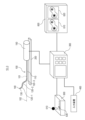
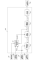
- FIG. 1 is a schematic diagram showing an example of the schematic configuration of a continuum robot control system 10-1 according to the first embodiment of the present invention.
- the continuum robot control system 10-1 as shown in FIG. ing.
- the continuum robot 100 is a tubular path penetrating the inside of the long part 110 and the bending part 120, and through a tool insertion opening provided near the junction between the long part 110 and the drive unit 150.
- a tool channel 101 is provided for inserting and removing various tools.
- Various tools to be inserted into and removed from the tool channel 101 include an imaging tool having an imaging unit 140 at its tip, and surgical instruments such as biopsy tools such as a biopsy brush tool and a biopsy needle tool.
- the long portion 110 corresponds to a plurality of linear members driven by the drive unit 150 when bending the bending portion 120 with respect to the reference axis 102.
- a plurality of drive wires are inserted through.
- the bending portion 120 is configured to be able to actively change its posture. Specifically, the bending portion 120 is moved relative to the reference axis 102 by driving a drive wire, which is a linear member connected to the bending portion 120 , by an actuator (driving portion) installed inside the drive unit 150 . curve.
- the reference axis 102 is assumed to be an axis parallel to the moving direction of the continuous body robot 100 on the linear stage 200 .
- the coil 130 is installed at the tip of the bending portion 120 . Also, although not shown in FIG. 1, a magnetic field generator is installed near the bending section 120 . By reading changes in the magnetic field generated by a magnetic field generator (not shown) via the coil 130 , the control device 300 can detect the tip position and direction of the bending section 120 .
- the imaging unit 140 is a component having a camera function, which is provided at the tip of an imaging tool inserted into the tool channel 101, for example.
- the tool channel 101 is provided with a guide member, and the imaging unit 140 of the imaging tool inserted into the tool channel 101 is inserted to a predetermined insertion depth and phase in the vicinity of the tip of the bending portion 120. placed in
- the drive unit 150 includes an actuator (driving section) that drives a drive wire that is a linear member connected to the bending section 120 when bending the bending section 120 at a desired bending angle with respect to the reference axis 102 .
- an actuator driving section
- the driving unit 150 is fixed to the linear stage 200, and the continuum robot 100 moves in the longitudinal direction of the linear stage 200 by pushing and pulling the driving unit 150 back and forth by a user such as a doctor. Perform linear motion.
- the drive unit 150 is fixed to the linear stage 200 as described above.
- the linear stage 200 corresponds to a moving device that moves the continuous robot 100 forward and backward with respect to a subject (subject).
- the control device 300 controls the operation of the continuous robot 100 based on, for example, an operation input from the operation device 500, an input from the input device 400, an input from the coil 130, and an image output from the imaging unit 140. It is a device. Further, the control device 300 performs various types of control including display control of the image display device 600 and various types of processing.
- the input device 400 is a device that inputs various information (including various data and various images) to the control device 300 .
- the operating device 500 is a device operated by a user such as a doctor.
- the operating device 500 is provided with a lever 510 that is operated by a user such as a doctor so that the bending portion 120 assumes a desired posture.
- the control device 300 outputs a wire drive command to the actuator (driving section) of the drive unit 150 based on the operation amount of the lever 510 so that the bending section 120 assumes a desired posture.
- control device 300 is provided with an interface for receiving the image acquired by the imaging unit 140, and the image received by the control device 300 from the imaging unit 140 is output to the image display device 600 and is used by the camera. It is displayed as image 610 .
- the image display device 600 also displays, for example, a navigation image 620 created from a 3D model of the subject's lungs constructed before surgery.
- the navigation image 620 includes, for example, an image obtained by observing the lumen of a 3D model of the lung, which is the subject, from a first-person viewpoint, and a bird's-eye view of the 3D model of the lung, which is the subject, observed from the outside of the subject.
- a user such as a doctor, can switch between these images as needed.
- FIG. 2 is a schematic diagram showing an example of a schematic configuration of the continuous body robot 100 according to the first embodiment of the present invention.
- the same reference numerals are assigned to the same components as those shown in FIG. 1, and detailed description thereof will be omitted. 2, the imaging unit 140 shown in FIG. 1 is not shown.
- the elongated portion 110 is a member that passively bends against an external force.
- the bending portion 120 includes a plurality of drive wires 121-123 which are a plurality of linear members, and a plurality of wire guides 124 which are members for guiding the plurality of drive wires 121-123.
- one end of the three drive wires 121 to 123 is fixedly connected to the wire guide 124D arranged at the tip 120a of the bending portion 120, and the other end is connected to the actuators 151a to 153a through the drive transmission mechanism. It is connected.
- the wire guide 124D arranged at the distal end 120a of the bending portion 120 is equipped with the coil 130 described above.
- actuators 151a to 153a and feed screws 151b to 153b shown in FIG. 2 are provided inside the drive unit 150 shown in FIG. 1, actuators 151a to 153a and feed screws 151b to 153b shown in FIG. 2 are provided.
- the drive wire 121 is connected to the actuator 151a via the feed screw 151b.
- the drive wire 122 is connected to the actuator 152a via a feed screw 152b.
- the drive wire 123 is connected to the actuator 153a via a feed screw 153b.
- the respective actuators 151a to 153a push and pull the respective drive wires 121 to 123 along the longitudinal direction of the continuous body robot 100 based on the control of the control device 300, thereby moving the bending portion 120 with respect to the reference axis 102. can be curved.
- the rotary motions of the actuators 151a-153a are decelerated by the feed screws 151b-153b connected to their respective output shafts and converted into translational motion.
- the nuts of the feed screws 151b to 153b are provided with wire grips for fixing the drive wires 121 to 123.
- the actuators 151a to 153a are driven, the drive wires 121 to 123 move in the longitudinal direction of the continuous robot 100. pushed and pulled along.
- the drive wires 121 to 123 are fixedly connected to the wire guide 124D arranged at the tip 120a of the bending portion 120 in different phases, the drive amounts of the actuators 151a to 153a (each drive wire 121 to 123), it is possible to bend the bending portion 120 in a desired bending angle and direction.
- the drive wires 121 to 123 are not fixed to the elongated portion 110, the orientation of the elongated portion 110 does not change even if the drive wires 121 to 123 are pushed or pulled.
- FIG. 3 is a schematic diagram showing an example of the schematic configuration of the bending portion 120 shown in FIG.
- the same components as those shown in FIG. 2 are denoted by the same reference numerals, and detailed description thereof will be omitted.
- All three drive wires 121 to 123 are connected to a wire guide 124D arranged at the tip of the bending portion 120 (hereinafter sometimes referred to as the "distal end").
- the wire guides 124 other than the wire guide 124D are connected only to the drive wires 121, and the drive wires 122 and 123 are connected continuously along guide holes (not shown) provided in the wire guides 124.
- the body robot 100 can slide in the longitudinal direction.
- a working coordinate system based on a subject such as a patient
- a robot coordinate system based on the drive unit 150 and the tip of the bending portion 120 are Use the reference camera coordinate system.
- a predetermined position in the trachea of the subject is the origin OW
- the direction from the larynx to the lungs of the subject is the Z axis ZW
- the direction from the abdomen to the back is the Y axis YW , YW and Z
- FIG. 4 is a schematic diagram showing a robot coordinate system and a camera coordinate system used for control by the continuum robot control system 10-1 according to the first embodiment of the present invention.
- the same components as those shown in FIGS. 1 to 3 are denoted by the same reference numerals, and detailed description thereof will be omitted.
- the drive wire 121 shown in FIGS. 2 and 3 is referred to as "1a wire”
- the drive wire 122 illustrated in FIGS. 123 is described as "1c wire”.
- the center of the base near the joint between the long part 110 of the continuous body robot 100 and the drive unit 150 is the origin OB .
- the longitudinal direction of the elongated portion 110 is the Z-axis ZB
- the direction of the 1a wire is set with respect to the X-axes XB , XB , and ZB with the origin OB as a reference.
- the Z-axis ZB is equivalent to the reference axis 102, as shown in FIG.
- the guide member provided in the tool channel 101 described above determines the position and posture of the imaging section 140 (camera) with respect to the tip (distal end) of the bending section 120 . Therefore, in this embodiment, the camera coordinate system is defined with the distal end of the continuum robot 100 as a reference.
- the guide member described above regulates the amount of insertion of the imaging section 140 so that the center of the light receiving section of the imaging section 140 coincides with the center of the wire guide 124D arranged at the distal end of the bending section 120.
- the center of the wire guide 124D is the origin OI of the camera coordinate system.
- the guide member described above defines the phase of the imaging unit 140 so that the direction from the origin OI shown in FIG.
- the top left subscript is used to indicate in which coordinate system the vector is defined.
- the upper left subscript W represents a work coordinate system
- the upper left subscript B represents a robot coordinate system
- the upper left subscript I represents a vector when observed from a camera coordinate system.
- the tip position vectors of the bending section 120 represented by the robot coordinate system and the work coordinate system are respectively B p 1 and W p 1 .
- the bending angle ⁇ 1 in FIG. 3 representing the magnitude of bending and the turning angle ⁇ 1 in FIG. 3 representing the bending direction are defined.
- the unit vector n 1 in the longitudinal direction at the distal end of the bending section 120 and the Z-axis Z B of the robot coordinate system (“reference axis 102” as shown in FIG. 4) ) is defined as the bending angle ⁇ 1 of the bending portion 120 .
- the vector obtained by projecting the unit vector n 1 onto the X B -Y B plane is defined as W B
- the angle between W B and X B is defined as the turning angle ⁇ 1 of the bending portion 120 .
- kinematics hereinafter referred to as “actuator motion ) are represented by the following formulas (1) to (3), respectively.
- robot kinematics representing the relationship between the position p 1 and the direction n 1 of the tip of the bending portion 120 in the robot coordinate system and the bending angle ⁇ 1 and turning angle ⁇ 1 of the bending portion 120 (hereinafter referred to as “robot kinematics”) described) are represented by the following equations (4) and (5), respectively.
- R g represents the pitch circle diameter of the wire passing through the wire guide 124 and l 1d represents the length of the central axis of the bending portion 120 .
- FIG. 5 is a schematic diagram showing an example of the schematic configuration of the control device 300 according to the first embodiment of the present invention.
- a control device 300 shown in FIG. 1 A control device 300 shown in FIG.
- structural information 301 is obtained by, for example, a user such as a doctor inputting structural information of a subject such as a patient (for example, structural information of a lung lumen) from the input device 400 before surgery.
- a bending portion tip position 302 is position information of the tip 120 a of the bending portion 120 measured by the coil 130 .
- the bending portion operation input 303 is, for example, input information of an operation amount when a user such as a doctor operates the lever 510 of the operation device 500 .
- the angle limit value estimating unit 311 calculates the input 3D model of the subject including the structural information 301 of the subject, the position p1 and the direction of the distal end of the bending portion 120 included in the input bending portion tip position 302. n 1 , and the current target bending angle ⁇ 1_ref and the target turning angle ⁇ 1_ref output from the angle limiter 313, a certain turning angle (certain bending direction) ⁇ 1 is determined by iterative calculation in FIG.
- the bending angle limit value ⁇ 1 — lim ( ⁇ 1 ) of the bending portion 120 with respect to is calculated and estimated.
- the angle command generation unit 312 generates a bending angle command value ⁇ 1_cmd and the turning angle command value ⁇ 1_cmd are generated by calculation.
- the angle limiter 313 adjusts the bending angle limit value ⁇ 1 — lim ( ⁇ 1 ) of the bending portion 120 output from the angle limit value estimator 311 (for example, less than or equal to the bending angle limit value ⁇ 1 — lim ( ⁇ 1 )).
- the target bending angle ⁇ 1_ref is set to limit the driving of the actuators 151a to 153a, which are the driving units.
- the angle limiter 313 first obtains a bending angle limit value ⁇ 1 — lim ( ⁇ 1 — cmd ) corresponding to the bending angle command value ⁇ 1 — cmd output from the angle command generator 312 .
- the angle limiting unit 313 controls the bending angle command value ⁇ 1_cmd and the turning angle command value output from the angle command generating unit 312. .zeta.1_cmd are output as the target bending angle .theta.1_ref and the target turning angle .zeta.1_ref , respectively.
- the angle limiting unit 313 outputs the current target bending angle ⁇ 1_ref without updating it.
- the kinematics calculation unit 314 uses the actuator kinematics shown in formulas (1) to (3) to calculate the wire 1a, the wire 1b from the target bending angle ⁇ 1_ref and the target turning angle ⁇ 1_ref output from the angle limiter 313.
- the drive amounts l 1a , l 1b and l 1c of the wire and the 1c wire are calculated.
- the wire control unit 315 controls the actuator 151a so that the actual drive amounts of the 1a wire, 1b wire and 1c wire match the drive amounts l 1a , l 1b and l 1c calculated by the kinematics calculation unit 314, respectively.
- a wire drive command 304 is output to 153a.
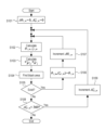
- FIG. 6 is a flow chart showing an example of iterative calculation processing procedure when obtaining the bending angle limit value ⁇ 1 — lim ( ⁇ 1 ) in the angle limit value estimating unit 311 of FIG. 5 .
- the angle limit value estimating unit 311 calculates a predetermined direction ⁇ 1_in and a predetermined magnitude ⁇ 1_in when the lever 510 is moved in a predetermined direction ⁇ 1_in by a predetermined magnitude ⁇ 1_in . Initialize (set to 0) ⁇ 1_in .
- step S102 the angle limit value estimation unit 311 outputs the bending angle ⁇ 1_itr and the turning angle ⁇ 1_itr when it is assumed that the lever 510 is moved in a predetermined direction ⁇ 1_in by a predetermined amount ⁇ 1_in . It is calculated by a method similar to that of the generation unit 312 .
- step S103 the angle limit value estimator 311 calculates the position of the tip (distal end) of the bending portion 120 after the lever 510 is operated, using a calculation method based on the configuration of the block diagram of FIG. 7, which will be described later. Calculate W p ⁇ 1 ' and direction W n ⁇ 1 '.
- step S104 the angle limit value estimating unit 311 uses the structural information 301 to observe the direction represented by Wn ⁇ 1 ′ with the position Wp ⁇ 1 ′ as the base point, and when the imaging unit 140 An image of the inside of the subject (for example, the lungs) to be output is estimated.
- the angle limit value estimation unit 311 determines whether or not the estimated image includes a part of the path leading to the deep part of the lumen of the subject (for example, the lungs). Specifically, first, the angle limit value estimating unit 311 divides the estimated image into black for the path toward the deep part of the lumen of the subject (for example, lung) and white for the other areas. binarization processing based on Then, in step S104, the angle limit value estimation unit 311 detects a black area (hereinafter referred to as a "characteristic area”) from the binarized image.
- a black area hereinafter referred to as a "characteristic area
- step S105 the angle limit value estimation unit 311 determines whether or not the feature area detected in step S104 is included with a predetermined area or more. That is, in step S105, the angle limit value estimating unit 311 determines that the visual field of the imaging unit 140 (the image obtained by the imaging unit 140) includes a characteristic region related to the path of the lumen of the subject (for example, the lungs) having a predetermined area. Determine whether or not it is included.
- step S105 if the characteristic region detected in step S104 is included with a predetermined area or more (S105/Yes), the route to the deep part of the lumen of the subject (for example, lung) enters the field of view of the imaging unit 140, and the process proceeds to step S106.
- step S106 the angle limit value estimator 311 updates the bending angle limit value ? 1_lim (? 1_itr ) of the bending portion 120 to the bending angle ? 1_itr .
- step S107 the angle limit value estimator 311 increases the predetermined magnitude ⁇ 1_in .
- the process returns to step S102.
- step S105 if the feature area detected in step S104 does not have a predetermined area or more (S105/No), the process proceeds to step S108.
- the angle limit value estimator 311 determines whether or not the predetermined direction ⁇ 1_in is less than 360 degrees.
- step S108 if the predetermined direction ⁇ 1_in is less than 360 degrees (S108/Yes), the process proceeds to step S109.
- step S109 the angle limit value estimator 311 increases the predetermined direction ⁇ 1_in . After that, the process returns to step S102.
- step S108 If the predetermined direction ⁇ 1_in is not less than 360 deg as a result of determination in step S108 (S108/No), the processing of the flowchart of FIG. 6 ends.
- the operation direction ⁇ 1_in of the lever 510 is gradually increased from 0 deg to 360 deg, and each time, the limit (for example, upper limit) of the bending angle ⁇ 1_lim ( By calculating ⁇ 1 — itr ), it is possible to obtain the bending angle limit value ⁇ 1 — lim ( ⁇ 1 ) of the bending portion 120 corresponding to all the operation directions.
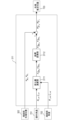
- FIG. 7 is a schematic diagram showing an example of the functional configuration of the angle limit value estimating section 311 that performs the process of step S103 in FIG. 7, in step S103 of FIG. 6, the angle limit value estimator 311 determines the position W p ⁇ 1 ′ of the tip (distal end) of the bending section 120 when a predetermined lever operation is assumed, and A method for calculating the estimated value of the direction W n ⁇ 1 ′ will now be described. Moreover, in FIG. 7, the same reference numerals are assigned to the same components as those shown in FIG. 5, and detailed description thereof will be omitted.
- the angle limit value estimation unit 311 that performs the process of step S103 in FIG. 6 has a functional configuration of a change amount calculation unit 3111 and a coordinate conversion unit 3112, as shown in FIG.
- the operation angle 701 is the bending angle ⁇ 1_itr and the turning angle ⁇ 1_itr calculated in step S102 of FIG.
- a bending portion angle 702 is the target bending angle ⁇ 1_ref and the target turning angle ⁇ 1_ref output from the angle limiting portion 313 in FIG.
- the change amount calculation unit 3111 in FIG . the position B p 1_ref and the direction B n 1_ref .
- the change amount calculation unit 3111 calculates the post-movement position B p 1_itr and the direction B n 1_itr of the distal end from the bending angle ⁇ 1_itr and the turning angle ⁇ 1_itr , which are the operation angle 701 .
- the change amount calculation unit 3111 subtracts the position B p 1_ref and the direction B n 1_ref before the movement from the calculated position B p 1_itr and the direction B n 1_itr after the movement to obtain the change amounts B ⁇ p 1 and Calculate B ⁇ n 1 .
- a coordinate transformation unit 3112 in FIG. 7 converts the amount of change B ⁇ p 1 and B ⁇ n 1 calculated by the amount of change calculation unit 3111 into the amount of change W ⁇ p 1 and W ⁇ into the working coordinate system. Calculate n1 .
- the angle limit value estimation unit 311 calculates the change amounts W ⁇ p 1 and W ⁇ n 1 calculated by the coordinate conversion unit 3112 and the bending portion 120 measured by the coil 130 at the bending portion tip position 302.
- the position W p 1 and the direction W n 1 of the tip (distal end) are respectively added to calculate the position W p ⁇ 1 ' and the direction W n ⁇ 1 '.
- the position W p ⁇ 1 ′ and direction W n ⁇ 1 ′ calculated here are output as the estimated tip position 703 .
- [1-4: Lung biopsy processing procedure] A processing procedure of a method for limiting the bending angle of the bending portion 120 when lung biopsy is performed on a subject using the continuum robot control system 10-1 described above will be described.
- the user creates a 3D model of the lungs of a subject (subject) from medical images such as MRI images and CT images.
- the user determines the target position for sampling the tissue and the target path through which the tip 120a of the bending portion 120 of the continuous robot 100 passes until reaching the target position while referring to the created 3D model.
- the user stores the determined target position and target route information together with the 3D model in the storage unit (not shown) of the control device 300 .
- a user such as a doctor first inserts an imaging tool having an imaging unit 140 at its tip into the tool channel 101 of the continuous robot 100, and moves the imaging unit 140 of the imaging tool up to the tip 120a of the bending portion 120. insert.
- the user inserts the continuum robot 100 into which the imaging tool is inserted through the subject's mouth or nose.
- the user operates the operation device 500 (lever 510, etc.) while referring to the camera image 610 and the navigation image 620 displayed on the image display device 600, and continuously controls the posture of the tip 120a of the bending portion 120.
- the linear stage 200 on which the driving unit 150 of the body robot 100 is mounted is advanced.
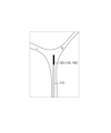
- FIGS. 8A, 8B, and 8C show the first embodiment of the present invention, and are diagrams showing an example of the posture of the continuous robot 100 inside the subject. 8A, 8B, and 8C, the same components as those shown in FIGS. 1 to 4 are denoted by the same reference numerals, and detailed description thereof will be omitted.
- 9A, 9B, and 9C show the first embodiment of the present invention, and camera images output by the imaging unit 140 when the continuous robot 100 takes the postures of FIGS. 8A, 8B, and 8C. It is a figure which shows an example. 8A, 8B, 8C and 9A, 9B, 9C will be described below.
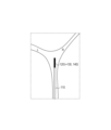
- FIG. 8A shows, for example, a lumen wall (lumen inner wall) 900, and a lumen route 911 toward the depth of the route L (910) corresponding to the characteristic region described above and a route R (920) toward the depth.
- Lumen path 921 is shown.
- the bending section 120 having the coil 130 and the imaging section 140 at its tip is further bent to the left to increase the bending angle.
- part of the path L (910) is out of the screen, and the area of the lumen path 911 corresponding to the characteristic region is reduced. Resulting in.
- the bending portion operation input 303 for further bending the bending portion 120 to the left is input.
- the control device 300 controls the bending section 120 not to bend further to the left (predetermined direction).
- the angle limiting unit 313 holds a different bending angle limit value ⁇ 1 — lim ( ⁇ ) for each turning angle ⁇ , the vertical direction or rightward direction (other than the predetermined direction) of the screen where the area of the feature region increases direction), the bending angle of the bending portion 120 is not limited.
- a characteristic region related to the path of the lumen of the subject is always displayed on the camera image 610, so that the user can change the operation direction of the bending section 120. can be easily grasped. This reduces the risk of erroneously operating the bending section 120 in the direction of strong contact with the lumen of the subject and damaging the continuum robot 100 .
- the area of the characteristic region is calculated based on the difference in brightness between the luminal wall of the lung, which is the subject, and the path leading to the deep part of the luminal region of the lung.
- the calculation method of the feature regions in 300 is not limited.
- information other than the lumen may be used as long as it can be distinguished from the background.
- a characteristic region may be defined using information on a difference in brightness caused by irregularities such as a tumor or folds present on the luminal wall of the subject, or edge information generated by branching or curving of the luminal wall of the subject. .
- the area of the characteristic region is calculated using the camera image estimated by the angle limit value estimation unit 311. good too.
- the lumen and unevenness behind the lumen wall on the front surface as the characteristic region. operability of the bending portion 120 can be improved.
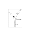
- FIGS. 10A, 10B, and 10C are diagrams showing an example of a form in which the bending angle limit value of the bending portion 120 of the continuous body robot 100 according to the first embodiment of the present invention can be increased.
- FIGS. 10A, 10B, and 10C configurations similar to those shown in FIGS. 8A, 8B, 8C, and 9A, 9B, and 9C are denoted by the same reference numerals, and the detailed description thereof is as follows. omitted.
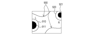
- FIG. 10A is a diagram showing an example of the posture of the continuous robot 100 inside the subject.
- the path L continues behind the lumen wall A as viewed from the continuum robot 100 .
- FIG. 10B only the lumen wall A is included in the field of view (camera image) of the imaging unit 140, and the characteristic region described above does not exist. Therefore, when only the camera image is used, the bending section 120 cannot be operated in the posture shown in FIG. 10A.
- FIG. 10C an image including the path L can be generated if the lumen wall A is transmitted.
- this transmitted image is used as navigation image 620, or route L (910) extracted from the transmitted image by image processing is superimposed on camera image 610, the user can navigate bending portion 120 while referring to information on route L. Since the operation direction can be determined, the path L can be used as the feature area (911). Thereby, the bending angle limit value of the bending portion 120 can be increased so as to take the posture shown in FIG. 10A.
- the above-described characteristic regions may be set based on the preoperatively planned target route to the affected area (region of interest) inside the subject.
- the target path information is superimposed on the 3D model of the tissue to estimate the camera image 610 including the target path.
- the curving angle limit value of the curving portion 120 may be calculated so that the estimated camera image 610 always includes part of the target route.
- the controller 300 of the continuum robot control system 10-1 performs the following processing.
- the control device 300 detects the bending portion detected after the bending portion 120 is inserted into the lumen of the subject (for example, the lungs of the subject). Based on the tip position 302 and the structural information 301 of the lumen, when the bending section 120 is bent in a predetermined direction, the field of view of the imaging section 140 includes a characteristic region related to the path of the lumen with a predetermined area or more.
- the bending angle limit value ⁇ 1 — lim ( ⁇ 1 ) of the bending portion 120 at the time of bending is estimated.
- the control device 300 causes the bending portion 120 to be bent within the range of the bending angle limit value ⁇ 1 — lim ( ⁇ 1 ).
- the driving of the actuators 151a to 153a, which are driving portions, is limited so as to bend.
- the bending angle of the bending section 120 can be controlled so that the characteristic region related to the luminal path of the subject is always within the field of view of the imaging section 140. Moreover, even for a subject whose shape changes during surgery, it is possible to reduce the risk of operating the continuous body robot 100 in a direction that strongly contacts the lumen of the subject.
- the first embodiment also includes a method of processing performed by the continuum robot control system 10-1 (continuum robot control method).
- the control device 300 of the present embodiment also limits the amount of movement of the linear stage 200 so that the area of the above-described characteristic region is equal to or greater than a predetermined area.
- FIG. 11 is a schematic diagram showing an example of a schematic configuration of a continuum robot control system 10-2 according to the second embodiment of the present invention.
- the same components as those shown in FIG. 1 are denoted by the same reference numerals, and detailed description thereof will be omitted.
- the continuum robot control system 10-2 includes a continuum robot 100, a linear stage 200, an electric stage 220, a control device 300, an input device 400, an operation device 500, and an image display device 600, as shown in FIG. is configured as
- the linear stage 200 is driven by an electric stage 220 including electric actuators.
- the linear stage 200 and the electric stage 220 correspond to a moving device that moves the continuous body robot 100 forward and backward with respect to the subject.
- the operating device 500 in the second embodiment is provided with a forward/backward button 520 (a forward button and a reverse button) for outputting a forward/backward movement command for the motorized stage 220 .
- the control device 300 outputs a drive command to the electric actuator of the electric stage 220 according to the type of button that was pushed.
- the rotary motion of the electric actuator is converted into translational motion by the feed screw, and the driving unit 150 moves forward and backward together with the table of the electric stage 220 (forward and backward movement).
- An encoder (not shown) is connected to the electric actuator of the electric stage 220, and the control device 300 calculates the amount of movement of the table (stage) based on the output of this encoder.
- FIG. 12 is a schematic diagram showing an example of the schematic configuration of the control device 300 according to the second embodiment of the present invention.
- the same components as those shown in FIG. 5 are denoted by the same reference numerals, and detailed description thereof will be omitted.
- the control device 300 shown in FIG. 12 has a movement limit value estimation section 321, a movement command calculation section 322, a movement amount limitation section 323, and a stage control section 324 in addition to the components 311 to 315 shown in FIG. configured as follows.
- Components 321 to 324 shown in FIG. 12 are components related to the control system of the electric stage 220 .
- the stage operation input 305 is, for example, input information about the type of button and the amount of operation when the forward/reverse button 520 of the operating device 500 is operated by a user such as a doctor.
- the movement limit value estimator 321 uses iterative calculation in the same manner as the angle limit value estimator 311 described in the first embodiment, and calculates the position of the bending portion 120 included in the input structural information 301 and the bending portion tip position 302. Based on the position p1 and the direction n1 of the distal end, a movement limit value zb_lim in the amount of movement of the stage is calculated and estimated. Specifically, the movement limit value estimation unit 321 first estimates the position and direction of the imaging unit 140 when the stage is moved by a predetermined amount. to estimate Then, the movement limit value estimating unit 321 determines whether or not the characteristic region in the estimated image is included with a predetermined area or more.
- the movement limit value estimation unit 321 repeats the above-described processing while increasing the movement amount of the stage, and outputs the maximum stage movement amount at which the characteristic region is included in the estimated image as the movement limit value zb_lim . .
- a movement command calculation unit 322 calculates a stage position command value zb cmd based on the stage operation input 305 .
- Movement amount limiter 323 outputs position command value zb cmd as target position zb ref if position command value zb cmd calculated by movement command calculator 322 is equal to or less than movement limit value zb lim . Further, if the position command value zb cmd calculated by the movement command calculation unit 322 is greater than the movement limit value zb lim , the movement amount limiter 323 outputs the movement limit value zb lim as the target position zb ref .
- the stage control unit 324 outputs the stage drive command 306 so that the stage position measured by the encoder connected to the electric actuator of the electric stage 220 matches the target position zb ref .
- FIGS. 13A, 13B, and 13C show the second embodiment of the present invention, and are diagrams showing an example of the posture of the continuous robot 100 inside the subject.
- FIGS. 13A, 13B, and 13C configurations similar to those shown in FIGS. 1 to 4, 8A, 8B, 8C, and 11 are given the same reference numerals, and detailed description thereof is omitted.
- 14A, 14B, and 14C show a second embodiment of the present invention, in which camera images output by the imaging unit 140 when the continuous robot 100 assumes the postures of FIGS. 13A, 13B, and 13C. It is a figure which shows an example.
- FIGS. 14A, 14B, and 14C the same reference numerals are assigned to the same configurations as those shown in FIGS. 9A, 9B, and 9C, and detailed description thereof will be omitted.
- 13A, 13B, 13C, 14A, 14B, and 14C a method of controlling the motorized stage 220 during lung biopsy of the subject will be
- the tip of the bending section 120 having the coil 130 and the imaging section 140 at the tip reaches the vicinity of the bifurcation in the lung lumen of the subject.
- both paths, path L (910) in FIG. 13A on the left side of the screen and path R (920) in FIG. 13A on the right side of the screen. come in.
- the tip of the bending section 120 having the coil 130 and the imaging section 140 at the tip approaches the branch.
- the path L (910) moves to the left and the path R (920) moves to the right, as shown in FIG. 14B.
- the distal end of the bending section 120 having the coil 130 and the imaging section 140 at the distal end becomes closer to the branch.
- the movement amount limiter 323 performs control to limit the forward movement of the stage.
- the movement amount limiter 323 of the stage and the angle limiter 313 of the bending angle of the bending portion 120 are independent of each other. It is possible to perform bending movements. For example, when the camera image shown in FIG. 14C is obtained, if the bending section 120 is bent to the left, the path L (910) moves to the vicinity of the center of the camera image, and if the bending section 120 is bent to the right, Since path R (920) moves near the center of the camera image, not limiting the bending angle of bending section 120 is also applicable. Then, when the feature area becomes equal to or larger than a predetermined area by such a bending operation, the restriction on the amount of movement of the stage is lifted, so that the stage can be moved forward again.
- the control device 300 of the continuous body robot control system 10-2 according to the second embodiment performs the following processing in addition to the processing of the control device 300 according to the first embodiment.
- the movement limit value estimating unit 321 (movement estimating means) of the control device 300 detects the bending portion detected after the bending portion 120 is inserted into the lumen of the subject (for example, the lungs of the subject). Based on the tip position 302 and the structural information 301 of the lumen, a movement limit value zb_lim in the amount of movement by the linear stage 200 and the motorized stage 220, which are moving devices, is estimated. Then, the control device 300 controls the movement amount of the linear stage 200 and the electric stage 220, which are moving devices, to be within the range of the movement limit value zb lim in the movement amount limiting unit 323 (movement amount limiting means). I have to.
- the continuous body robot 100 is largely moved with respect to the subject, and the characteristic region is prevented from deviating from the field of view (camera image 610) of the imaging unit 140. be able to.
- the electric actuator of the electric stage 220 is used to limit the amount of movement of the stage, but the present invention can also be applied to other embodiments.
- a stage that can be manually moved forward by the user, an encoder that measures the amount of movement of the stage, and an electromagnetic brake that regulates the movement of the stage in the forward and backward directions. can also be taken.
- the stage is moved by the user's operation, and when the movement amount zb measured by the encoder becomes equal to or greater than the target position zb lim, the movement amount is made smaller than the target position zb lim by applying an electromagnetic brake. It becomes possible to
- the elongated portion 110 of the continuum robot 100 can bend passively when in contact with the lumen of the subject, but traverses a highly curved path. Occasionally, they come into strong contact with the lumen of the subject.
- the posture of each bending portion 120 is actively controlled so as to conform to the shape of the lumen of the subject using the continuous body robot 100 having a plurality of bending portions 120, the lumen of the subject and the It is possible to reduce the risk of deterioration of operability due to contact with the continuum robot 100 and damage to the continuum robot 100 .
- the continuous body robot 100 having a plurality of bending parts 120 is applied, and even when operating the bending parts 120 other than the tip (distal end), the above-described feature in the camera image 610
- the bending angle of the bending portion 120 is limited so that the region is included.
- FIG. 15 is a schematic diagram showing an example of a schematic configuration of a continuum robot control system 10-3 according to the third embodiment of the present invention.
- the same reference numerals are assigned to the same components as those shown in FIGS. 1 and 11, and detailed description thereof will be omitted.
- a continuum robot control system 10-3 according to the third embodiment differs from the first and second embodiments described above in that the continuum robot 100 includes a plurality of bending sections 120-1 to 120-3. .
- a user such as a doctor uses a lever 510 installed on the operating device 500 to move one of the bending portions 120-1 to 120-3, as in the continuum robot control system 10-1 according to the first embodiment. It is possible to change the bending angle and posture of one bending portion 120 of .
- the operation device 500 is provided with the slide switch 530, and the user can operate by changing the position of the slider of the slide switch 530.
- the curved portion 120 can be selected to
- FIG. 16 is a schematic diagram showing an example of a plurality of bending sections 120 provided in the continuous body robot 100 according to the third embodiment of the present invention.
- the same components as those shown in FIGS. 2 to 4 and 15 are denoted by the same reference numerals, and detailed description thereof will be omitted.
- the number of bending portions 120 is N.
- the n-th curved portion 120-n one ends of the drive wires 121-n, 122-n and 123-n are connected to the wire guide 124-nD located at the distal end of the plurality of wire guides 124-n. Fixedly connected.
- the drive wires 121-n shown in FIG. 16 are referred to as "na wires", the drive wires 122-n illustrated in FIG.
- nb wires are referred to as "nb wires", and the drive wires 123-n illustrated in FIG. ”.
- na wire is fixed to the wire guides 124-n other than the wire guide 124-nD at the distal end of the n-th bending portion 120-n. It can be slid in the longitudinal direction by a guide hole (not shown) provided in n.
- the (n ⁇ 1)th bending portion 120-(n ⁇ 1), the nth bending portion 120-n, and the (n+1)th bending portion 120- are shown in order from the tip of the continuous body robot 100.
- (n+1) three bends 120 are shown.
- the (n ⁇ 1)th curved portion 120-(n ⁇ 1) shown in FIG. 16 corresponds to the first curved portion 120-1 shown in FIG.
- the nth curved portion 120-n shown in FIG. 16 corresponds to the second curved portion 120-2 shown in FIG.
- the (n+1)th curved portion 120-(n+1 ) corresponds to the third curved portion 120-3 shown in FIG.
- the wire guides of the (n+1)-th bending portion 120-(n+1) located closer to the base than the n-th bending portion 120-n include na wire, nb wire and nc wire. are not fixed, and each wire slides through the guide hole of the wire guide. Then, each wire passing through the (n+1)-th bending portion 120-(n+1) corresponding to the N-th bending portion located closest to the base portion is guided by the long portion 110, It is connected to an actuator, which is the driving part shown in the figure.
- the actuator kinematics representing the relationship between the bending angle ⁇ n and turning angle ⁇ n of the n-th bending portion 120-n and the drive amounts l na , l nb , and l nc of the na wire, nb wire, and nc wire is represented by the following formulas (6) to (8).
- the continuum robot 100 of this embodiment can independently control the orientation of each bending section 120 .
- the robot kinematics representing the angle and position B p 1 of the tip of the first flexure 120-1 can be determined using the kinematics of each flexure 120.
- the control device 300 transforms these vectors into a coordinate system having the base of each bending section 120 as the origin and the coordinate axes X B , Y B and Z B of the robot coordinate system as the coordinate axes. Controller 300 then adds these vectors to obtain position B p 1 .
- the direction n 1 of the tip of the first bending portion 120-1 depends only on the bending angle ⁇ 1 and the turning angle ⁇ 1 of the first bending portion 120-1.
- n1 can be obtained using the equation (5).
- FIG. 17 is a schematic diagram showing an example of the schematic configuration of the control device 300 according to the third embodiment of the present invention.
- the same reference numerals are assigned to the same components as those shown in FIGS. 5 and 12, and detailed description thereof will be omitted.
- control device 300 shown in FIG. is configured with
- the bending section selection signal 307 is a selection signal for one bending section 120 selected by a user such as a doctor by operating the slide switch 530 of the operating device 500 .
- the angle limit value estimator 311 calculates the position p 1 and direction n 1 of the distal end of the first bending portion 120-1 included in the input structural information 301 and bending portion tip position 302. , the number n of the bending section 120 to be operated indicated by the bending section selection signal 307, and the target bending angle ⁇ n_ref and the target turning angle ⁇ n_ref of the n-th bending section 120-n output from the angle limiting section 313. Based on this, an image output by the imaging unit 140 when the n-th bending unit 120-n is driven is estimated.
- the angle limit value estimating unit 311 calculates the maximum bending angle at which the characteristic region in the estimated image is included in a predetermined area or more by the iterative calculation described in the first embodiment. Output as the bending angle limit value ⁇ n_lim ( ⁇ n ) of n.
- the angle command generation unit 312 generates the horizontal tilt amount rx and the vertical tilt amount ry of the lever 510 included in the input bending portion operation input 303, and the bending portion selection signal 307.
- a bending angle command value ⁇ n_cmd and a turning angle command value ⁇ n_cmd for the n-th bending portion 120-n are generated by calculation based on the number n of the bending portion 120 to be operated indicated by .
- the angle limiter 313 is within the range of the bending angle limit value ⁇ n_lim ( ⁇ n ) of the n-th bending portion 120-n output from the angle limit value estimating unit 311 (for example, the bending angle limit
- the target bending angle ⁇ n_ref is set so as to limit the driving of the actuator, which is the driving unit, so that the value ⁇ 1 — lim ( ⁇ 1 ).
- the kinematics calculation unit 314 uses the kinematics shown in formulas (6) to (8) to calculate the target bending angle ⁇ n_ref and the target turning angle ⁇ n_ref output from the angle limiter 313. , the driving amounts l na , l nb and l nc of the na wire, nb wire and nc wire of the n-th bending portion 120-n are calculated.
- the wire control unit 315 compares the actual na wire, nb wire, and nc wire drive amounts with the drive amounts lna , lnb , and lnc calculated by the kinematics calculator 314, respectively.
- a wire drive command 304 is output to each actuator so that
- the control device 300 of the continuous robot control system 10-3 performs the following processing on the continuous robot 100 having a plurality of bending sections 120.
- the angle limit value estimating unit 311 detects the bending portions 120 after the plurality of bending portions 120 are inserted into the lumen of the subject (for example, the lungs of the subject).
- a bending section selection signal 307 selection information
- the field of view of the imaging unit 140 includes a characteristic region related to the path of the lumen with a predetermined area or more.
- the bending angle limit value ⁇ n_lim ( ⁇ n ) of the bending portion 120-n is estimated.
- the control device 300 controls the bending angle limit value of the n-th bending portion 120-n.
- the driving of the actuator which is the driving section, is limited so that the n-th bending section 120-n bends within the range of ⁇ n_lim ( ⁇ n ).
- the present invention supplies a program that implements one or more functions of the above-described embodiments to a system or device via a network or a storage medium, and one or more processors in the computer of the system or device reads and executes the program. It can also be realized by processing to It can also be implemented by a circuit (for example, ASIC) that implements one or more functions.
- a circuit for example, ASIC
- This program and computer-readable storage media storing the program are included in the present invention.
Landscapes
- Health & Medical Sciences (AREA)
- Life Sciences & Earth Sciences (AREA)
- Surgery (AREA)
- Nuclear Medicine, Radiotherapy & Molecular Imaging (AREA)
- Biomedical Technology (AREA)
- Optics & Photonics (AREA)
- Pathology (AREA)
- Radiology & Medical Imaging (AREA)
- Biophysics (AREA)
- Engineering & Computer Science (AREA)
- Physics & Mathematics (AREA)
- Heart & Thoracic Surgery (AREA)
- Medical Informatics (AREA)
- Molecular Biology (AREA)
- Animal Behavior & Ethology (AREA)
- General Health & Medical Sciences (AREA)
- Public Health (AREA)
- Veterinary Medicine (AREA)
- Endoscopes (AREA)
Abstract
L'invention concerne un dispositif de commande (300) qui : estime, sur la base de la position d'extrémité distale d'une partie de courbure (120) d'un robot continuum (100) détectée après que la partie de courbure (120) est insérée dans une lumière d'un sujet et d'informations concernant la structure de la lumière, la valeur limite d'angle de l'angle de courbure de la partie de courbure (120) lorsqu'une région de caractéristique associée au trajet de la lumière est incluse dans une zone prescrite ou plus au sein du champ de vision d'une unité d'imagerie (140) dans un cas dans lequel la partie de courbure (120) est courbée dans une direction prescrite ; et limite l'entraînement d'une unité d'entraînement (150) de telle sorte que la partie de courbure (120) se courbe dans la plage de la valeur limite d'angle estimée lorsque la partie de courbure (120) est courbée dans la direction prescrite.
Applications Claiming Priority (2)
| Application Number | Priority Date | Filing Date | Title |
|---|---|---|---|
| JP2022015558A JP2023113300A (ja) | 2022-02-03 | 2022-02-03 | 連続体ロボット制御システム及び連続体ロボット制御方法 |
| JP2022-015558 | 2022-02-03 |
Publications (1)
| Publication Number | Publication Date |
|---|---|
| WO2023149232A1 true WO2023149232A1 (fr) | 2023-08-10 |
Family
ID=87552088
Family Applications (1)
| Application Number | Title | Priority Date | Filing Date |
|---|---|---|---|
| PCT/JP2023/001646 WO2023149232A1 (fr) | 2022-02-03 | 2023-01-20 | Système de commande de robot continuum et procédé de commande de robot continuum |
Country Status (2)
| Country | Link |
|---|---|
| JP (1) | JP2023113300A (fr) |
| WO (1) | WO2023149232A1 (fr) |
Citations (5)
| Publication number | Priority date | Publication date | Assignee | Title |
|---|---|---|---|---|
| JP2009136618A (ja) * | 2007-12-10 | 2009-06-25 | Olympus Medical Systems Corp | 内視鏡システム |
| WO2012132638A1 (fr) * | 2011-03-30 | 2012-10-04 | オリンパスメディカルシステムズ株式会社 | Système d'endoscope |
| JP2018175602A (ja) * | 2017-04-18 | 2018-11-15 | キヤノン株式会社 | 連続体ロボットシステムの制御装置、連続体ロボットシステムの制御方法、プログラム |
| JP2018176406A (ja) * | 2017-04-21 | 2018-11-15 | キヤノン株式会社 | 連続体ロボットの制御システム及びその制御方法、並びに、プログラム |
| WO2021192593A1 (fr) * | 2020-03-26 | 2021-09-30 | Hoya株式会社 | Programme, procédé de traitement d'informations, dispositif de traitement d'informations et système d'aide au diagnostic |
-
2022
- 2022-02-03 JP JP2022015558A patent/JP2023113300A/ja active Pending
-
2023
- 2023-01-20 WO PCT/JP2023/001646 patent/WO2023149232A1/fr unknown
Patent Citations (5)
| Publication number | Priority date | Publication date | Assignee | Title |
|---|---|---|---|---|
| JP2009136618A (ja) * | 2007-12-10 | 2009-06-25 | Olympus Medical Systems Corp | 内視鏡システム |
| WO2012132638A1 (fr) * | 2011-03-30 | 2012-10-04 | オリンパスメディカルシステムズ株式会社 | Système d'endoscope |
| JP2018175602A (ja) * | 2017-04-18 | 2018-11-15 | キヤノン株式会社 | 連続体ロボットシステムの制御装置、連続体ロボットシステムの制御方法、プログラム |
| JP2018176406A (ja) * | 2017-04-21 | 2018-11-15 | キヤノン株式会社 | 連続体ロボットの制御システム及びその制御方法、並びに、プログラム |
| WO2021192593A1 (fr) * | 2020-03-26 | 2021-09-30 | Hoya株式会社 | Programme, procédé de traitement d'informations, dispositif de traitement d'informations et système d'aide au diagnostic |
Also Published As
| Publication number | Publication date |
|---|---|
| JP2023113300A (ja) | 2023-08-16 |
Similar Documents
| Publication | Publication Date | Title |
|---|---|---|
| US11896316B2 (en) | Systems and methods for generating anatomic tree structures using backward pathway growth | |
| US11419689B2 (en) | Guide apparatus for delivery of a flexible instrument and methods of use | |
| AU2018345516B2 (en) | Robotic system with indication of boundary for robotic arm | |
| JP7371026B2 (ja) | 管状網の経路ベースのナビゲーション | |
| US20230049292A1 (en) | Multiple-input instrument position determination | |
| JP7154832B2 (ja) | 形状推定をともなう軌道情報による位置合わせの改良 | |
| US20200129045A1 (en) | Method and system for assisting an operator in endoscopic navigation | |
| CN107660134B (zh) | 图像引导手术记录的系统和方法 | |
| EP3058889B1 (fr) | Système médical fournissant un enregistrement dynamique d'un modèle d'une structure anatomique pour chirurgie guidée par image | |
| WO2019079126A1 (fr) | Affichage d'images préopératoires et intra-opératoires | |
| KR20180104764A (ko) | 영상-안내 수술에서 정합되는 형광투시 영상을 사용하기 위한 시스템 및 방법 | |
| CN105188594B (zh) | 根据解剖特征对内窥镜的机器人控制 | |
| US20220156923A1 (en) | Systems and methods for connecting segmented structures | |
| WO2023149232A1 (fr) | Système de commande de robot continuum et procédé de commande de robot continuum | |
| US20220354380A1 (en) | Endoscope navigation system with updating anatomy model | |
| US20220202500A1 (en) | Intraluminal navigation using ghost instrument information | |
| WO2023145377A1 (fr) | Système de commande de robot à corps continu et procédé de commande de robot à corps continu | |
| US20220202274A1 (en) | Medical system with medical device overlay display | |
| US20240180631A1 (en) | Systems and methods for generating anatomic tree structures using backward pathway growth | |
| US20220202502A1 (en) | Method for visualization and orientation guidance during endoscopy procedure | |
| WO2023154246A1 (fr) | Interface utilisateur graphique de bronchoscope à navigation améliorée | |
| CN116940298A (zh) | 来自单个感应拾取线圈传感器的六个自由度 | |
| EP4333682A1 (fr) | Système de navigation endoscopique comportant un modèle anatomique se mettant à jour | |
| CN116829089A (zh) | 用于基于术中成像更新图形用户界面的系统 |
Legal Events
| Date | Code | Title | Description |
|---|---|---|---|
| 121 | Ep: the epo has been informed by wipo that ep was designated in this application |
Ref document number: 23749548 Country of ref document: EP Kind code of ref document: A1 |