WO2023149232A1 - Continuum robot control system and continuum robot control method - Google Patents
Continuum robot control system and continuum robot control method Download PDFInfo
- Publication number
- WO2023149232A1 WO2023149232A1 PCT/JP2023/001646 JP2023001646W WO2023149232A1 WO 2023149232 A1 WO2023149232 A1 WO 2023149232A1 JP 2023001646 W JP2023001646 W JP 2023001646W WO 2023149232 A1 WO2023149232 A1 WO 2023149232A1
- Authority
- WO
- WIPO (PCT)
- Prior art keywords
- bending
- bending portion
- angle
- lumen
- limit value
- Prior art date
Links
Images


Classifications
-
- A—HUMAN NECESSITIES
- A61—MEDICAL OR VETERINARY SCIENCE; HYGIENE
- A61B—DIAGNOSIS; SURGERY; IDENTIFICATION
- A61B1/00—Instruments for performing medical examinations of the interior of cavities or tubes of the body by visual or photographical inspection, e.g. endoscopes; Illuminating arrangements therefor
- A61B1/005—Flexible endoscopes
Definitions
- the present invention relates to a continuum robot control system and a continuum robot control method for controlling a continuum robot equipped with an imaging unit.
- minimally invasive medicine In recent years, attention has been focused on minimally invasive medicine to reduce the burden on subjects such as patients and improve QOL after treatment and examination.
- a representative example of minimally invasive medicine is surgery and examination using an endoscope.
- laparoscopic surgery can reduce surgical wounds compared to conventional open surgery, so it has the merit of not only shortening the required hospital stay after surgery but also being cosmetically superior.
- a flexible endoscope is known as an endoscope used in minimally invasive medicine.
- the insertion section inserted into the inside of the subject is made of a bendable member, it can be used even in curved organs such as the esophagus, large intestine, and lungs without compressing the tissue. It can be inserted inside the subject to reduce the burden on the subject.
- the actuator is used to drive the insertion section of the flexible endoscope, and the posture of the insertion section is automatically controlled so as to follow the internal path of the subject, the burden on the subject can be further reduced. can be expected. Therefore, research and development of a mechanism of a continuum robot that can be used as a flexible endoscope and a control method thereof have been actively conducted.
- a user When inserting such a continuum robot into the lumen of a subject, a user such as a doctor needs to operate the continuum robot so as not to make strong contact with the lumen. This is because when the continuum robot comes into contact with the lumen, the continuum robot moves in a direction different from the direction intended by the user due to the force acting between the continuum robot and the lumen, resulting in poor operability. to put away. Furthermore, if the continuum robot makes strong contact with the lumen, the continuum robot may be damaged.
- the user refers to the image of the image pickup unit (camera) installed in the insertion part of the continuum robot, or the 2D image such as the preoperative CT or MRI medical image, while viewing the continuum. operate the robot.
- the image pickup unit camera
- Patent Document 1 describes an example of a continuous body robot that limits the bending angle of a bending portion that is an insertion portion based on the volume of an organ to be inspected or treated. .
- a working space having a volume equivalent to the volume of the heart is defined with the heart as the target, and the insertion section is configured so that the operating range of the distal end of the robot is limited within the working space.
- the bending angle of a certain bending portion is controlled.
- the present invention has been made in view of such problems, and an object of the present invention is to provide a mechanism that can reduce the risk of operating a continuum robot in a direction that strongly contacts the lumen of a subject. .
- a continuum robot control system includes a bending portion that bends with respect to a reference axis by driving a linear member, a driving portion that drives the linear member, and a driving portion that is arranged near the tip of the bending portion. and a control device for controlling an operation of the continuous robot, wherein the control device is configured such that the bending portion is a tube of a subject to be inspected.
- the control device is configured such that the bending portion is a tube of a subject to be inspected.
- angle estimating means for estimating an angle limit value of the bending angle of the bending portion when a characteristic region related to the path of the cavity is included in a predetermined area or more; and angle limiting means for limiting the driving of the driving portion so that the bending portion bends within the range of the angle limiting value.
- the present invention also includes a continuum robot control method by the continuum robot control system described above.
- FIG. 1 is a schematic diagram showing an example of a schematic configuration of a continuum robot control system according to a first embodiment of the present invention
- FIG. 1 is a schematic diagram showing an example of a schematic configuration of a continuous body robot according to a first embodiment of the present invention
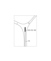
- FIG. 3 is a schematic diagram showing an example of a schematic configuration of a bending portion shown in FIG. 2
- FIG. 3 is a schematic diagram showing a robot coordinate system and a camera coordinate system used in control by the continuum robot control system according to the first embodiment of the present invention
- 1 is a schematic diagram showing an example of a schematic configuration of a control device according to a first embodiment of the present invention
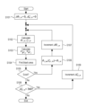
- FIG. 6 is a flow chart showing an example of a procedure of iterative calculation when obtaining a bending angle limit value in the angle limit value estimating unit of FIG. 5;
- FIG. FIG. 7 is a schematic diagram showing an example of the functional configuration of an angle limit value estimating unit that performs the process of step S103 in FIG. 6;
- FIG. 4 is a diagram showing the first embodiment of the present invention and showing an example of the posture of the continuous body robot inside the subject;
- FIG. 4 is a diagram showing the first embodiment of the present invention and showing an example of the posture of the continuous body robot inside the subject;
- FIG. 4 is a diagram showing the first embodiment of the present invention and showing an example of the posture of the continuous body robot inside the subject;
- FIG. 4 is a diagram showing the first embodiment of the present invention and showing an example of the posture of the continuous body robot inside the subject;
- FIG. 8B shows the first embodiment of the present invention, and shows an example of a camera image output by the imaging unit when the continuum robot assumes the postures of FIGS. 8A, 8B, and 8C.
- FIG. 8B shows the first embodiment of the present invention, and shows an example of a camera image output by the imaging unit when the continuum robot assumes the postures of FIGS. 8A, 8B, and 8C.
- FIG. 8B shows the first embodiment of the present invention, and shows an example of a camera image output by the imaging unit when the continuum robot assumes the postures of FIGS. 8A, 8B, and 8C.
- FIG. 8B shows the first embodiment of the present invention, and shows an example of a camera image output by the imaging unit when the continuum robot assumes the postures of FIGS. 8A, 8B, and 8C.
- FIG. 5 is a diagram showing an example of a mode in which the bending angle limit value of the bending portion of the continuous body robot according to the first embodiment of the present invention can be increased;
- FIG. 5 is a diagram showing an example of a mode in which the bending angle limit value of the bending portion of the continuous body robot according to the first embodiment of the present invention can be increased;
- FIG. 5 is a diagram showing an example of a mode in which the bending angle limit value of the bending portion of the continuous body robot according to the first embodiment of the present invention can be increased;
- FIG. 5 is a diagram showing an example of a mode in which the bending angle limit value of the bending portion of the continuous body robot according to the first embodiment of the present invention can be increased;
- FIG. 5 is a schematic diagram showing an example of a schematic configuration of a continuous body robot control system according to a second embodiment of the present invention; It is a schematic diagram which shows an example of schematic structure of the control apparatus which concerns on the 2nd Embodiment of this invention.
- FIG. 10 is a diagram showing the second embodiment of the present invention and showing an example of the posture of the continuous robot inside the subject;
- FIG. 10 is a diagram showing the second embodiment of the present invention and showing an example of the posture of the continuous robot inside the subject;
- FIG. 10 is a diagram showing the second embodiment of the present invention and showing an example of the posture of the continuous robot inside the subject; 13A, 13B, and 13C, showing an example of a camera image output by the imaging unit when the continuum robot assumes the postures of FIGS.
- FIG. 13A, 13B, and 13C showing an example of a camera image output by the imaging unit when the continuum robot assumes the postures of FIGS. 13A, 13B, and 13C, according to the second embodiment of the present invention
- FIG. 13A, 13B, and 13C showing an example of a camera image output by the imaging unit when the continuum robot assumes the postures of FIGS. 13A, 13B, and 13C, according to the second embodiment of the present invention
- FIG. FIG. 11 is a schematic diagram showing an example of a schematic configuration of a continuous body robot control system according to a third embodiment of the present invention.
- FIG. 11 is a schematic diagram showing an example of a plurality of bending portions provided in a continuous body robot according to a third embodiment of the present invention. It is a schematic diagram which shows an example of schematic structure of the control apparatus which concerns on the 3rd Embodiment of this invention.
- a continuum robot control system including a continuum robot having a bending section capable of bending in three dimensions and a control device for controlling the motion of the continuum robot
- the configuration of the continuous robot control system according to this embodiment will be described, and then the configuration of the continuous robot according to this embodiment will be described. Subsequently, a method for limiting the bending angle of the bending portion in the control device will be explained, and finally an example of a procedure for collecting a sample from the deep part of the lung (subject) of a subject such as a patient will be explained.
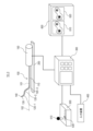
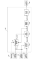
- FIG. 1 is a schematic diagram showing an example of the schematic configuration of a continuum robot control system 10-1 according to the first embodiment of the present invention.
- the continuum robot control system 10-1 as shown in FIG. ing.
- the continuum robot 100 is a tubular path penetrating the inside of the long part 110 and the bending part 120, and through a tool insertion opening provided near the junction between the long part 110 and the drive unit 150.
- a tool channel 101 is provided for inserting and removing various tools.
- Various tools to be inserted into and removed from the tool channel 101 include an imaging tool having an imaging unit 140 at its tip, and surgical instruments such as biopsy tools such as a biopsy brush tool and a biopsy needle tool.
- the long portion 110 corresponds to a plurality of linear members driven by the drive unit 150 when bending the bending portion 120 with respect to the reference axis 102.
- a plurality of drive wires are inserted through.
- the bending portion 120 is configured to be able to actively change its posture. Specifically, the bending portion 120 is moved relative to the reference axis 102 by driving a drive wire, which is a linear member connected to the bending portion 120 , by an actuator (driving portion) installed inside the drive unit 150 . curve.
- the reference axis 102 is assumed to be an axis parallel to the moving direction of the continuous body robot 100 on the linear stage 200 .
- the coil 130 is installed at the tip of the bending portion 120 . Also, although not shown in FIG. 1, a magnetic field generator is installed near the bending section 120 . By reading changes in the magnetic field generated by a magnetic field generator (not shown) via the coil 130 , the control device 300 can detect the tip position and direction of the bending section 120 .
- the imaging unit 140 is a component having a camera function, which is provided at the tip of an imaging tool inserted into the tool channel 101, for example.
- the tool channel 101 is provided with a guide member, and the imaging unit 140 of the imaging tool inserted into the tool channel 101 is inserted to a predetermined insertion depth and phase in the vicinity of the tip of the bending portion 120. placed in
- the drive unit 150 includes an actuator (driving section) that drives a drive wire that is a linear member connected to the bending section 120 when bending the bending section 120 at a desired bending angle with respect to the reference axis 102 .
- an actuator driving section
- the driving unit 150 is fixed to the linear stage 200, and the continuum robot 100 moves in the longitudinal direction of the linear stage 200 by pushing and pulling the driving unit 150 back and forth by a user such as a doctor. Perform linear motion.
- the drive unit 150 is fixed to the linear stage 200 as described above.
- the linear stage 200 corresponds to a moving device that moves the continuous robot 100 forward and backward with respect to a subject (subject).
- the control device 300 controls the operation of the continuous robot 100 based on, for example, an operation input from the operation device 500, an input from the input device 400, an input from the coil 130, and an image output from the imaging unit 140. It is a device. Further, the control device 300 performs various types of control including display control of the image display device 600 and various types of processing.
- the input device 400 is a device that inputs various information (including various data and various images) to the control device 300 .
- the operating device 500 is a device operated by a user such as a doctor.
- the operating device 500 is provided with a lever 510 that is operated by a user such as a doctor so that the bending portion 120 assumes a desired posture.
- the control device 300 outputs a wire drive command to the actuator (driving section) of the drive unit 150 based on the operation amount of the lever 510 so that the bending section 120 assumes a desired posture.
- control device 300 is provided with an interface for receiving the image acquired by the imaging unit 140, and the image received by the control device 300 from the imaging unit 140 is output to the image display device 600 and is used by the camera. It is displayed as image 610 .
- the image display device 600 also displays, for example, a navigation image 620 created from a 3D model of the subject's lungs constructed before surgery.
- the navigation image 620 includes, for example, an image obtained by observing the lumen of a 3D model of the lung, which is the subject, from a first-person viewpoint, and a bird's-eye view of the 3D model of the lung, which is the subject, observed from the outside of the subject.
- a user such as a doctor, can switch between these images as needed.
- FIG. 2 is a schematic diagram showing an example of a schematic configuration of the continuous body robot 100 according to the first embodiment of the present invention.
- the same reference numerals are assigned to the same components as those shown in FIG. 1, and detailed description thereof will be omitted. 2, the imaging unit 140 shown in FIG. 1 is not shown.
- the elongated portion 110 is a member that passively bends against an external force.
- the bending portion 120 includes a plurality of drive wires 121-123 which are a plurality of linear members, and a plurality of wire guides 124 which are members for guiding the plurality of drive wires 121-123.
- one end of the three drive wires 121 to 123 is fixedly connected to the wire guide 124D arranged at the tip 120a of the bending portion 120, and the other end is connected to the actuators 151a to 153a through the drive transmission mechanism. It is connected.
- the wire guide 124D arranged at the distal end 120a of the bending portion 120 is equipped with the coil 130 described above.
- actuators 151a to 153a and feed screws 151b to 153b shown in FIG. 2 are provided inside the drive unit 150 shown in FIG. 1, actuators 151a to 153a and feed screws 151b to 153b shown in FIG. 2 are provided.
- the drive wire 121 is connected to the actuator 151a via the feed screw 151b.
- the drive wire 122 is connected to the actuator 152a via a feed screw 152b.
- the drive wire 123 is connected to the actuator 153a via a feed screw 153b.
- the respective actuators 151a to 153a push and pull the respective drive wires 121 to 123 along the longitudinal direction of the continuous body robot 100 based on the control of the control device 300, thereby moving the bending portion 120 with respect to the reference axis 102. can be curved.
- the rotary motions of the actuators 151a-153a are decelerated by the feed screws 151b-153b connected to their respective output shafts and converted into translational motion.
- the nuts of the feed screws 151b to 153b are provided with wire grips for fixing the drive wires 121 to 123.
- the actuators 151a to 153a are driven, the drive wires 121 to 123 move in the longitudinal direction of the continuous robot 100. pushed and pulled along.
- the drive wires 121 to 123 are fixedly connected to the wire guide 124D arranged at the tip 120a of the bending portion 120 in different phases, the drive amounts of the actuators 151a to 153a (each drive wire 121 to 123), it is possible to bend the bending portion 120 in a desired bending angle and direction.
- the drive wires 121 to 123 are not fixed to the elongated portion 110, the orientation of the elongated portion 110 does not change even if the drive wires 121 to 123 are pushed or pulled.
- FIG. 3 is a schematic diagram showing an example of the schematic configuration of the bending portion 120 shown in FIG.
- the same components as those shown in FIG. 2 are denoted by the same reference numerals, and detailed description thereof will be omitted.
- All three drive wires 121 to 123 are connected to a wire guide 124D arranged at the tip of the bending portion 120 (hereinafter sometimes referred to as the "distal end").
- the wire guides 124 other than the wire guide 124D are connected only to the drive wires 121, and the drive wires 122 and 123 are connected continuously along guide holes (not shown) provided in the wire guides 124.
- the body robot 100 can slide in the longitudinal direction.
- a working coordinate system based on a subject such as a patient
- a robot coordinate system based on the drive unit 150 and the tip of the bending portion 120 are Use the reference camera coordinate system.
- a predetermined position in the trachea of the subject is the origin OW
- the direction from the larynx to the lungs of the subject is the Z axis ZW
- the direction from the abdomen to the back is the Y axis YW , YW and Z
- FIG. 4 is a schematic diagram showing a robot coordinate system and a camera coordinate system used for control by the continuum robot control system 10-1 according to the first embodiment of the present invention.
- the same components as those shown in FIGS. 1 to 3 are denoted by the same reference numerals, and detailed description thereof will be omitted.
- the drive wire 121 shown in FIGS. 2 and 3 is referred to as "1a wire”
- the drive wire 122 illustrated in FIGS. 123 is described as "1c wire”.
- the center of the base near the joint between the long part 110 of the continuous body robot 100 and the drive unit 150 is the origin OB .
- the longitudinal direction of the elongated portion 110 is the Z-axis ZB
- the direction of the 1a wire is set with respect to the X-axes XB , XB , and ZB with the origin OB as a reference.
- the Z-axis ZB is equivalent to the reference axis 102, as shown in FIG.
- the guide member provided in the tool channel 101 described above determines the position and posture of the imaging section 140 (camera) with respect to the tip (distal end) of the bending section 120 . Therefore, in this embodiment, the camera coordinate system is defined with the distal end of the continuum robot 100 as a reference.
- the guide member described above regulates the amount of insertion of the imaging section 140 so that the center of the light receiving section of the imaging section 140 coincides with the center of the wire guide 124D arranged at the distal end of the bending section 120.
- the center of the wire guide 124D is the origin OI of the camera coordinate system.
- the guide member described above defines the phase of the imaging unit 140 so that the direction from the origin OI shown in FIG.
- the top left subscript is used to indicate in which coordinate system the vector is defined.
- the upper left subscript W represents a work coordinate system
- the upper left subscript B represents a robot coordinate system
- the upper left subscript I represents a vector when observed from a camera coordinate system.
- the tip position vectors of the bending section 120 represented by the robot coordinate system and the work coordinate system are respectively B p 1 and W p 1 .
- the bending angle ⁇ 1 in FIG. 3 representing the magnitude of bending and the turning angle ⁇ 1 in FIG. 3 representing the bending direction are defined.
- the unit vector n 1 in the longitudinal direction at the distal end of the bending section 120 and the Z-axis Z B of the robot coordinate system (“reference axis 102” as shown in FIG. 4) ) is defined as the bending angle ⁇ 1 of the bending portion 120 .
- the vector obtained by projecting the unit vector n 1 onto the X B -Y B plane is defined as W B
- the angle between W B and X B is defined as the turning angle ⁇ 1 of the bending portion 120 .
- kinematics hereinafter referred to as “actuator motion ) are represented by the following formulas (1) to (3), respectively.
- robot kinematics representing the relationship between the position p 1 and the direction n 1 of the tip of the bending portion 120 in the robot coordinate system and the bending angle ⁇ 1 and turning angle ⁇ 1 of the bending portion 120 (hereinafter referred to as “robot kinematics”) described) are represented by the following equations (4) and (5), respectively.
- R g represents the pitch circle diameter of the wire passing through the wire guide 124 and l 1d represents the length of the central axis of the bending portion 120 .
- FIG. 5 is a schematic diagram showing an example of the schematic configuration of the control device 300 according to the first embodiment of the present invention.
- a control device 300 shown in FIG. 1 A control device 300 shown in FIG.
- structural information 301 is obtained by, for example, a user such as a doctor inputting structural information of a subject such as a patient (for example, structural information of a lung lumen) from the input device 400 before surgery.
- a bending portion tip position 302 is position information of the tip 120 a of the bending portion 120 measured by the coil 130 .
- the bending portion operation input 303 is, for example, input information of an operation amount when a user such as a doctor operates the lever 510 of the operation device 500 .
- the angle limit value estimating unit 311 calculates the input 3D model of the subject including the structural information 301 of the subject, the position p1 and the direction of the distal end of the bending portion 120 included in the input bending portion tip position 302. n 1 , and the current target bending angle ⁇ 1_ref and the target turning angle ⁇ 1_ref output from the angle limiter 313, a certain turning angle (certain bending direction) ⁇ 1 is determined by iterative calculation in FIG.
- the bending angle limit value ⁇ 1 — lim ( ⁇ 1 ) of the bending portion 120 with respect to is calculated and estimated.
- the angle command generation unit 312 generates a bending angle command value ⁇ 1_cmd and the turning angle command value ⁇ 1_cmd are generated by calculation.
- the angle limiter 313 adjusts the bending angle limit value ⁇ 1 — lim ( ⁇ 1 ) of the bending portion 120 output from the angle limit value estimator 311 (for example, less than or equal to the bending angle limit value ⁇ 1 — lim ( ⁇ 1 )).
- the target bending angle ⁇ 1_ref is set to limit the driving of the actuators 151a to 153a, which are the driving units.
- the angle limiter 313 first obtains a bending angle limit value ⁇ 1 — lim ( ⁇ 1 — cmd ) corresponding to the bending angle command value ⁇ 1 — cmd output from the angle command generator 312 .
- the angle limiting unit 313 controls the bending angle command value ⁇ 1_cmd and the turning angle command value output from the angle command generating unit 312. .zeta.1_cmd are output as the target bending angle .theta.1_ref and the target turning angle .zeta.1_ref , respectively.
- the angle limiting unit 313 outputs the current target bending angle ⁇ 1_ref without updating it.
- the kinematics calculation unit 314 uses the actuator kinematics shown in formulas (1) to (3) to calculate the wire 1a, the wire 1b from the target bending angle ⁇ 1_ref and the target turning angle ⁇ 1_ref output from the angle limiter 313.
- the drive amounts l 1a , l 1b and l 1c of the wire and the 1c wire are calculated.
- the wire control unit 315 controls the actuator 151a so that the actual drive amounts of the 1a wire, 1b wire and 1c wire match the drive amounts l 1a , l 1b and l 1c calculated by the kinematics calculation unit 314, respectively.
- a wire drive command 304 is output to 153a.
- FIG. 6 is a flow chart showing an example of iterative calculation processing procedure when obtaining the bending angle limit value ⁇ 1 — lim ( ⁇ 1 ) in the angle limit value estimating unit 311 of FIG. 5 .
- the angle limit value estimating unit 311 calculates a predetermined direction ⁇ 1_in and a predetermined magnitude ⁇ 1_in when the lever 510 is moved in a predetermined direction ⁇ 1_in by a predetermined magnitude ⁇ 1_in . Initialize (set to 0) ⁇ 1_in .
- step S102 the angle limit value estimation unit 311 outputs the bending angle ⁇ 1_itr and the turning angle ⁇ 1_itr when it is assumed that the lever 510 is moved in a predetermined direction ⁇ 1_in by a predetermined amount ⁇ 1_in . It is calculated by a method similar to that of the generation unit 312 .
- step S103 the angle limit value estimator 311 calculates the position of the tip (distal end) of the bending portion 120 after the lever 510 is operated, using a calculation method based on the configuration of the block diagram of FIG. 7, which will be described later. Calculate W p ⁇ 1 ' and direction W n ⁇ 1 '.
- step S104 the angle limit value estimating unit 311 uses the structural information 301 to observe the direction represented by Wn ⁇ 1 ′ with the position Wp ⁇ 1 ′ as the base point, and when the imaging unit 140 An image of the inside of the subject (for example, the lungs) to be output is estimated.
- the angle limit value estimation unit 311 determines whether or not the estimated image includes a part of the path leading to the deep part of the lumen of the subject (for example, the lungs). Specifically, first, the angle limit value estimating unit 311 divides the estimated image into black for the path toward the deep part of the lumen of the subject (for example, lung) and white for the other areas. binarization processing based on Then, in step S104, the angle limit value estimation unit 311 detects a black area (hereinafter referred to as a "characteristic area”) from the binarized image.
- a black area hereinafter referred to as a "characteristic area
- step S105 the angle limit value estimation unit 311 determines whether or not the feature area detected in step S104 is included with a predetermined area or more. That is, in step S105, the angle limit value estimating unit 311 determines that the visual field of the imaging unit 140 (the image obtained by the imaging unit 140) includes a characteristic region related to the path of the lumen of the subject (for example, the lungs) having a predetermined area. Determine whether or not it is included.
- step S105 if the characteristic region detected in step S104 is included with a predetermined area or more (S105/Yes), the route to the deep part of the lumen of the subject (for example, lung) enters the field of view of the imaging unit 140, and the process proceeds to step S106.
- step S106 the angle limit value estimator 311 updates the bending angle limit value ? 1_lim (? 1_itr ) of the bending portion 120 to the bending angle ? 1_itr .
- step S107 the angle limit value estimator 311 increases the predetermined magnitude ⁇ 1_in .
- the process returns to step S102.
- step S105 if the feature area detected in step S104 does not have a predetermined area or more (S105/No), the process proceeds to step S108.
- the angle limit value estimator 311 determines whether or not the predetermined direction ⁇ 1_in is less than 360 degrees.
- step S108 if the predetermined direction ⁇ 1_in is less than 360 degrees (S108/Yes), the process proceeds to step S109.
- step S109 the angle limit value estimator 311 increases the predetermined direction ⁇ 1_in . After that, the process returns to step S102.
- step S108 If the predetermined direction ⁇ 1_in is not less than 360 deg as a result of determination in step S108 (S108/No), the processing of the flowchart of FIG. 6 ends.
- the operation direction ⁇ 1_in of the lever 510 is gradually increased from 0 deg to 360 deg, and each time, the limit (for example, upper limit) of the bending angle ⁇ 1_lim ( By calculating ⁇ 1 — itr ), it is possible to obtain the bending angle limit value ⁇ 1 — lim ( ⁇ 1 ) of the bending portion 120 corresponding to all the operation directions.
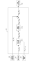
- FIG. 7 is a schematic diagram showing an example of the functional configuration of the angle limit value estimating section 311 that performs the process of step S103 in FIG. 7, in step S103 of FIG. 6, the angle limit value estimator 311 determines the position W p ⁇ 1 ′ of the tip (distal end) of the bending section 120 when a predetermined lever operation is assumed, and A method for calculating the estimated value of the direction W n ⁇ 1 ′ will now be described. Moreover, in FIG. 7, the same reference numerals are assigned to the same components as those shown in FIG. 5, and detailed description thereof will be omitted.
- the angle limit value estimation unit 311 that performs the process of step S103 in FIG. 6 has a functional configuration of a change amount calculation unit 3111 and a coordinate conversion unit 3112, as shown in FIG.
- the operation angle 701 is the bending angle ⁇ 1_itr and the turning angle ⁇ 1_itr calculated in step S102 of FIG.
- a bending portion angle 702 is the target bending angle ⁇ 1_ref and the target turning angle ⁇ 1_ref output from the angle limiting portion 313 in FIG.
- the change amount calculation unit 3111 in FIG . the position B p 1_ref and the direction B n 1_ref .
- the change amount calculation unit 3111 calculates the post-movement position B p 1_itr and the direction B n 1_itr of the distal end from the bending angle ⁇ 1_itr and the turning angle ⁇ 1_itr , which are the operation angle 701 .
- the change amount calculation unit 3111 subtracts the position B p 1_ref and the direction B n 1_ref before the movement from the calculated position B p 1_itr and the direction B n 1_itr after the movement to obtain the change amounts B ⁇ p 1 and Calculate B ⁇ n 1 .
- a coordinate transformation unit 3112 in FIG. 7 converts the amount of change B ⁇ p 1 and B ⁇ n 1 calculated by the amount of change calculation unit 3111 into the amount of change W ⁇ p 1 and W ⁇ into the working coordinate system. Calculate n1 .
- the angle limit value estimation unit 311 calculates the change amounts W ⁇ p 1 and W ⁇ n 1 calculated by the coordinate conversion unit 3112 and the bending portion 120 measured by the coil 130 at the bending portion tip position 302.
- the position W p 1 and the direction W n 1 of the tip (distal end) are respectively added to calculate the position W p ⁇ 1 ' and the direction W n ⁇ 1 '.
- the position W p ⁇ 1 ′ and direction W n ⁇ 1 ′ calculated here are output as the estimated tip position 703 .
- [1-4: Lung biopsy processing procedure] A processing procedure of a method for limiting the bending angle of the bending portion 120 when lung biopsy is performed on a subject using the continuum robot control system 10-1 described above will be described.
- the user creates a 3D model of the lungs of a subject (subject) from medical images such as MRI images and CT images.
- the user determines the target position for sampling the tissue and the target path through which the tip 120a of the bending portion 120 of the continuous robot 100 passes until reaching the target position while referring to the created 3D model.
- the user stores the determined target position and target route information together with the 3D model in the storage unit (not shown) of the control device 300 .
- a user such as a doctor first inserts an imaging tool having an imaging unit 140 at its tip into the tool channel 101 of the continuous robot 100, and moves the imaging unit 140 of the imaging tool up to the tip 120a of the bending portion 120. insert.
- the user inserts the continuum robot 100 into which the imaging tool is inserted through the subject's mouth or nose.
- the user operates the operation device 500 (lever 510, etc.) while referring to the camera image 610 and the navigation image 620 displayed on the image display device 600, and continuously controls the posture of the tip 120a of the bending portion 120.
- the linear stage 200 on which the driving unit 150 of the body robot 100 is mounted is advanced.
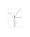
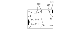
- FIGS. 8A, 8B, and 8C show the first embodiment of the present invention, and are diagrams showing an example of the posture of the continuous robot 100 inside the subject. 8A, 8B, and 8C, the same components as those shown in FIGS. 1 to 4 are denoted by the same reference numerals, and detailed description thereof will be omitted.
- 9A, 9B, and 9C show the first embodiment of the present invention, and camera images output by the imaging unit 140 when the continuous robot 100 takes the postures of FIGS. 8A, 8B, and 8C. It is a figure which shows an example. 8A, 8B, 8C and 9A, 9B, 9C will be described below.
- FIG. 8A shows, for example, a lumen wall (lumen inner wall) 900, and a lumen route 911 toward the depth of the route L (910) corresponding to the characteristic region described above and a route R (920) toward the depth.
- Lumen path 921 is shown.
- the bending section 120 having the coil 130 and the imaging section 140 at its tip is further bent to the left to increase the bending angle.
- part of the path L (910) is out of the screen, and the area of the lumen path 911 corresponding to the characteristic region is reduced. Resulting in.
- the bending portion operation input 303 for further bending the bending portion 120 to the left is input.
- the control device 300 controls the bending section 120 not to bend further to the left (predetermined direction).
- the angle limiting unit 313 holds a different bending angle limit value ⁇ 1 — lim ( ⁇ ) for each turning angle ⁇ , the vertical direction or rightward direction (other than the predetermined direction) of the screen where the area of the feature region increases direction), the bending angle of the bending portion 120 is not limited.
- a characteristic region related to the path of the lumen of the subject is always displayed on the camera image 610, so that the user can change the operation direction of the bending section 120. can be easily grasped. This reduces the risk of erroneously operating the bending section 120 in the direction of strong contact with the lumen of the subject and damaging the continuum robot 100 .
- the area of the characteristic region is calculated based on the difference in brightness between the luminal wall of the lung, which is the subject, and the path leading to the deep part of the luminal region of the lung.
- the calculation method of the feature regions in 300 is not limited.
- information other than the lumen may be used as long as it can be distinguished from the background.
- a characteristic region may be defined using information on a difference in brightness caused by irregularities such as a tumor or folds present on the luminal wall of the subject, or edge information generated by branching or curving of the luminal wall of the subject. .
- the area of the characteristic region is calculated using the camera image estimated by the angle limit value estimation unit 311. good too.
- the lumen and unevenness behind the lumen wall on the front surface as the characteristic region. operability of the bending portion 120 can be improved.
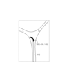
- FIGS. 10A, 10B, and 10C are diagrams showing an example of a form in which the bending angle limit value of the bending portion 120 of the continuous body robot 100 according to the first embodiment of the present invention can be increased.
- FIGS. 10A, 10B, and 10C configurations similar to those shown in FIGS. 8A, 8B, 8C, and 9A, 9B, and 9C are denoted by the same reference numerals, and the detailed description thereof is as follows. omitted.
- FIG. 10A is a diagram showing an example of the posture of the continuous robot 100 inside the subject.
- the path L continues behind the lumen wall A as viewed from the continuum robot 100 .
- FIG. 10B only the lumen wall A is included in the field of view (camera image) of the imaging unit 140, and the characteristic region described above does not exist. Therefore, when only the camera image is used, the bending section 120 cannot be operated in the posture shown in FIG. 10A.
- FIG. 10C an image including the path L can be generated if the lumen wall A is transmitted.
- this transmitted image is used as navigation image 620, or route L (910) extracted from the transmitted image by image processing is superimposed on camera image 610, the user can navigate bending portion 120 while referring to information on route L. Since the operation direction can be determined, the path L can be used as the feature area (911). Thereby, the bending angle limit value of the bending portion 120 can be increased so as to take the posture shown in FIG. 10A.
- the above-described characteristic regions may be set based on the preoperatively planned target route to the affected area (region of interest) inside the subject.
- the target path information is superimposed on the 3D model of the tissue to estimate the camera image 610 including the target path.
- the curving angle limit value of the curving portion 120 may be calculated so that the estimated camera image 610 always includes part of the target route.
- the controller 300 of the continuum robot control system 10-1 performs the following processing.
- the control device 300 detects the bending portion detected after the bending portion 120 is inserted into the lumen of the subject (for example, the lungs of the subject). Based on the tip position 302 and the structural information 301 of the lumen, when the bending section 120 is bent in a predetermined direction, the field of view of the imaging section 140 includes a characteristic region related to the path of the lumen with a predetermined area or more.
- the bending angle limit value ⁇ 1 — lim ( ⁇ 1 ) of the bending portion 120 at the time of bending is estimated.
- the control device 300 causes the bending portion 120 to be bent within the range of the bending angle limit value ⁇ 1 — lim ( ⁇ 1 ).
- the driving of the actuators 151a to 153a, which are driving portions, is limited so as to bend.
- the bending angle of the bending section 120 can be controlled so that the characteristic region related to the luminal path of the subject is always within the field of view of the imaging section 140. Moreover, even for a subject whose shape changes during surgery, it is possible to reduce the risk of operating the continuous body robot 100 in a direction that strongly contacts the lumen of the subject.
- the first embodiment also includes a method of processing performed by the continuum robot control system 10-1 (continuum robot control method).
- the control device 300 of the present embodiment also limits the amount of movement of the linear stage 200 so that the area of the above-described characteristic region is equal to or greater than a predetermined area.
- FIG. 11 is a schematic diagram showing an example of a schematic configuration of a continuum robot control system 10-2 according to the second embodiment of the present invention.
- the same components as those shown in FIG. 1 are denoted by the same reference numerals, and detailed description thereof will be omitted.
- the continuum robot control system 10-2 includes a continuum robot 100, a linear stage 200, an electric stage 220, a control device 300, an input device 400, an operation device 500, and an image display device 600, as shown in FIG. is configured as
- the linear stage 200 is driven by an electric stage 220 including electric actuators.
- the linear stage 200 and the electric stage 220 correspond to a moving device that moves the continuous body robot 100 forward and backward with respect to the subject.
- the operating device 500 in the second embodiment is provided with a forward/backward button 520 (a forward button and a reverse button) for outputting a forward/backward movement command for the motorized stage 220 .
- the control device 300 outputs a drive command to the electric actuator of the electric stage 220 according to the type of button that was pushed.
- the rotary motion of the electric actuator is converted into translational motion by the feed screw, and the driving unit 150 moves forward and backward together with the table of the electric stage 220 (forward and backward movement).
- An encoder (not shown) is connected to the electric actuator of the electric stage 220, and the control device 300 calculates the amount of movement of the table (stage) based on the output of this encoder.
- FIG. 12 is a schematic diagram showing an example of the schematic configuration of the control device 300 according to the second embodiment of the present invention.
- the same components as those shown in FIG. 5 are denoted by the same reference numerals, and detailed description thereof will be omitted.
- the control device 300 shown in FIG. 12 has a movement limit value estimation section 321, a movement command calculation section 322, a movement amount limitation section 323, and a stage control section 324 in addition to the components 311 to 315 shown in FIG. configured as follows.
- Components 321 to 324 shown in FIG. 12 are components related to the control system of the electric stage 220 .
- the stage operation input 305 is, for example, input information about the type of button and the amount of operation when the forward/reverse button 520 of the operating device 500 is operated by a user such as a doctor.
- the movement limit value estimator 321 uses iterative calculation in the same manner as the angle limit value estimator 311 described in the first embodiment, and calculates the position of the bending portion 120 included in the input structural information 301 and the bending portion tip position 302. Based on the position p1 and the direction n1 of the distal end, a movement limit value zb_lim in the amount of movement of the stage is calculated and estimated. Specifically, the movement limit value estimation unit 321 first estimates the position and direction of the imaging unit 140 when the stage is moved by a predetermined amount. to estimate Then, the movement limit value estimating unit 321 determines whether or not the characteristic region in the estimated image is included with a predetermined area or more.
- the movement limit value estimation unit 321 repeats the above-described processing while increasing the movement amount of the stage, and outputs the maximum stage movement amount at which the characteristic region is included in the estimated image as the movement limit value zb_lim . .
- a movement command calculation unit 322 calculates a stage position command value zb cmd based on the stage operation input 305 .
- Movement amount limiter 323 outputs position command value zb cmd as target position zb ref if position command value zb cmd calculated by movement command calculator 322 is equal to or less than movement limit value zb lim . Further, if the position command value zb cmd calculated by the movement command calculation unit 322 is greater than the movement limit value zb lim , the movement amount limiter 323 outputs the movement limit value zb lim as the target position zb ref .
- the stage control unit 324 outputs the stage drive command 306 so that the stage position measured by the encoder connected to the electric actuator of the electric stage 220 matches the target position zb ref .
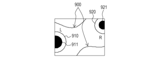
- FIGS. 13A, 13B, and 13C show the second embodiment of the present invention, and are diagrams showing an example of the posture of the continuous robot 100 inside the subject.
- FIGS. 13A, 13B, and 13C configurations similar to those shown in FIGS. 1 to 4, 8A, 8B, 8C, and 11 are given the same reference numerals, and detailed description thereof is omitted.
- 14A, 14B, and 14C show a second embodiment of the present invention, in which camera images output by the imaging unit 140 when the continuous robot 100 assumes the postures of FIGS. 13A, 13B, and 13C. It is a figure which shows an example.
- FIGS. 14A, 14B, and 14C the same reference numerals are assigned to the same configurations as those shown in FIGS. 9A, 9B, and 9C, and detailed description thereof will be omitted.
- 13A, 13B, 13C, 14A, 14B, and 14C a method of controlling the motorized stage 220 during lung biopsy of the subject will be
- the tip of the bending section 120 having the coil 130 and the imaging section 140 at the tip reaches the vicinity of the bifurcation in the lung lumen of the subject.
- both paths, path L (910) in FIG. 13A on the left side of the screen and path R (920) in FIG. 13A on the right side of the screen. come in.
- the tip of the bending section 120 having the coil 130 and the imaging section 140 at the tip approaches the branch.
- the path L (910) moves to the left and the path R (920) moves to the right, as shown in FIG. 14B.
- the distal end of the bending section 120 having the coil 130 and the imaging section 140 at the distal end becomes closer to the branch.
- the movement amount limiter 323 performs control to limit the forward movement of the stage.
- the movement amount limiter 323 of the stage and the angle limiter 313 of the bending angle of the bending portion 120 are independent of each other. It is possible to perform bending movements. For example, when the camera image shown in FIG. 14C is obtained, if the bending section 120 is bent to the left, the path L (910) moves to the vicinity of the center of the camera image, and if the bending section 120 is bent to the right, Since path R (920) moves near the center of the camera image, not limiting the bending angle of bending section 120 is also applicable. Then, when the feature area becomes equal to or larger than a predetermined area by such a bending operation, the restriction on the amount of movement of the stage is lifted, so that the stage can be moved forward again.
- the control device 300 of the continuous body robot control system 10-2 according to the second embodiment performs the following processing in addition to the processing of the control device 300 according to the first embodiment.
- the movement limit value estimating unit 321 (movement estimating means) of the control device 300 detects the bending portion detected after the bending portion 120 is inserted into the lumen of the subject (for example, the lungs of the subject). Based on the tip position 302 and the structural information 301 of the lumen, a movement limit value zb_lim in the amount of movement by the linear stage 200 and the motorized stage 220, which are moving devices, is estimated. Then, the control device 300 controls the movement amount of the linear stage 200 and the electric stage 220, which are moving devices, to be within the range of the movement limit value zb lim in the movement amount limiting unit 323 (movement amount limiting means). I have to.
- the continuous body robot 100 is largely moved with respect to the subject, and the characteristic region is prevented from deviating from the field of view (camera image 610) of the imaging unit 140. be able to.
- the electric actuator of the electric stage 220 is used to limit the amount of movement of the stage, but the present invention can also be applied to other embodiments.
- a stage that can be manually moved forward by the user, an encoder that measures the amount of movement of the stage, and an electromagnetic brake that regulates the movement of the stage in the forward and backward directions. can also be taken.
- the stage is moved by the user's operation, and when the movement amount zb measured by the encoder becomes equal to or greater than the target position zb lim, the movement amount is made smaller than the target position zb lim by applying an electromagnetic brake. It becomes possible to
- the elongated portion 110 of the continuum robot 100 can bend passively when in contact with the lumen of the subject, but traverses a highly curved path. Occasionally, they come into strong contact with the lumen of the subject.
- the posture of each bending portion 120 is actively controlled so as to conform to the shape of the lumen of the subject using the continuous body robot 100 having a plurality of bending portions 120, the lumen of the subject and the It is possible to reduce the risk of deterioration of operability due to contact with the continuum robot 100 and damage to the continuum robot 100 .
- the continuous body robot 100 having a plurality of bending parts 120 is applied, and even when operating the bending parts 120 other than the tip (distal end), the above-described feature in the camera image 610
- the bending angle of the bending portion 120 is limited so that the region is included.
- FIG. 15 is a schematic diagram showing an example of a schematic configuration of a continuum robot control system 10-3 according to the third embodiment of the present invention.
- the same reference numerals are assigned to the same components as those shown in FIGS. 1 and 11, and detailed description thereof will be omitted.
- a continuum robot control system 10-3 according to the third embodiment differs from the first and second embodiments described above in that the continuum robot 100 includes a plurality of bending sections 120-1 to 120-3. .
- a user such as a doctor uses a lever 510 installed on the operating device 500 to move one of the bending portions 120-1 to 120-3, as in the continuum robot control system 10-1 according to the first embodiment. It is possible to change the bending angle and posture of one bending portion 120 of .
- the operation device 500 is provided with the slide switch 530, and the user can operate by changing the position of the slider of the slide switch 530.
- the curved portion 120 can be selected to
- FIG. 16 is a schematic diagram showing an example of a plurality of bending sections 120 provided in the continuous body robot 100 according to the third embodiment of the present invention.
- the same components as those shown in FIGS. 2 to 4 and 15 are denoted by the same reference numerals, and detailed description thereof will be omitted.
- the number of bending portions 120 is N.
- the n-th curved portion 120-n one ends of the drive wires 121-n, 122-n and 123-n are connected to the wire guide 124-nD located at the distal end of the plurality of wire guides 124-n. Fixedly connected.
- the drive wires 121-n shown in FIG. 16 are referred to as "na wires", the drive wires 122-n illustrated in FIG.
- nb wires are referred to as "nb wires", and the drive wires 123-n illustrated in FIG. ”.
- na wire is fixed to the wire guides 124-n other than the wire guide 124-nD at the distal end of the n-th bending portion 120-n. It can be slid in the longitudinal direction by a guide hole (not shown) provided in n.
- the (n ⁇ 1)th bending portion 120-(n ⁇ 1), the nth bending portion 120-n, and the (n+1)th bending portion 120- are shown in order from the tip of the continuous body robot 100.
- (n+1) three bends 120 are shown.
- the (n ⁇ 1)th curved portion 120-(n ⁇ 1) shown in FIG. 16 corresponds to the first curved portion 120-1 shown in FIG.
- the nth curved portion 120-n shown in FIG. 16 corresponds to the second curved portion 120-2 shown in FIG.
- the (n+1)th curved portion 120-(n+1 ) corresponds to the third curved portion 120-3 shown in FIG.
- the wire guides of the (n+1)-th bending portion 120-(n+1) located closer to the base than the n-th bending portion 120-n include na wire, nb wire and nc wire. are not fixed, and each wire slides through the guide hole of the wire guide. Then, each wire passing through the (n+1)-th bending portion 120-(n+1) corresponding to the N-th bending portion located closest to the base portion is guided by the long portion 110, It is connected to an actuator, which is the driving part shown in the figure.
- the actuator kinematics representing the relationship between the bending angle ⁇ n and turning angle ⁇ n of the n-th bending portion 120-n and the drive amounts l na , l nb , and l nc of the na wire, nb wire, and nc wire is represented by the following formulas (6) to (8).
- the continuum robot 100 of this embodiment can independently control the orientation of each bending section 120 .
- the robot kinematics representing the angle and position B p 1 of the tip of the first flexure 120-1 can be determined using the kinematics of each flexure 120.
- the control device 300 transforms these vectors into a coordinate system having the base of each bending section 120 as the origin and the coordinate axes X B , Y B and Z B of the robot coordinate system as the coordinate axes. Controller 300 then adds these vectors to obtain position B p 1 .
- the direction n 1 of the tip of the first bending portion 120-1 depends only on the bending angle ⁇ 1 and the turning angle ⁇ 1 of the first bending portion 120-1.
- n1 can be obtained using the equation (5).
- FIG. 17 is a schematic diagram showing an example of the schematic configuration of the control device 300 according to the third embodiment of the present invention.
- the same reference numerals are assigned to the same components as those shown in FIGS. 5 and 12, and detailed description thereof will be omitted.
- control device 300 shown in FIG. is configured with
- the bending section selection signal 307 is a selection signal for one bending section 120 selected by a user such as a doctor by operating the slide switch 530 of the operating device 500 .
- the angle limit value estimator 311 calculates the position p 1 and direction n 1 of the distal end of the first bending portion 120-1 included in the input structural information 301 and bending portion tip position 302. , the number n of the bending section 120 to be operated indicated by the bending section selection signal 307, and the target bending angle ⁇ n_ref and the target turning angle ⁇ n_ref of the n-th bending section 120-n output from the angle limiting section 313. Based on this, an image output by the imaging unit 140 when the n-th bending unit 120-n is driven is estimated.
- the angle limit value estimating unit 311 calculates the maximum bending angle at which the characteristic region in the estimated image is included in a predetermined area or more by the iterative calculation described in the first embodiment. Output as the bending angle limit value ⁇ n_lim ( ⁇ n ) of n.
- the angle command generation unit 312 generates the horizontal tilt amount rx and the vertical tilt amount ry of the lever 510 included in the input bending portion operation input 303, and the bending portion selection signal 307.
- a bending angle command value ⁇ n_cmd and a turning angle command value ⁇ n_cmd for the n-th bending portion 120-n are generated by calculation based on the number n of the bending portion 120 to be operated indicated by .
- the angle limiter 313 is within the range of the bending angle limit value ⁇ n_lim ( ⁇ n ) of the n-th bending portion 120-n output from the angle limit value estimating unit 311 (for example, the bending angle limit
- the target bending angle ⁇ n_ref is set so as to limit the driving of the actuator, which is the driving unit, so that the value ⁇ 1 — lim ( ⁇ 1 ).
- the kinematics calculation unit 314 uses the kinematics shown in formulas (6) to (8) to calculate the target bending angle ⁇ n_ref and the target turning angle ⁇ n_ref output from the angle limiter 313. , the driving amounts l na , l nb and l nc of the na wire, nb wire and nc wire of the n-th bending portion 120-n are calculated.
- the wire control unit 315 compares the actual na wire, nb wire, and nc wire drive amounts with the drive amounts lna , lnb , and lnc calculated by the kinematics calculator 314, respectively.
- a wire drive command 304 is output to each actuator so that
- the control device 300 of the continuous robot control system 10-3 performs the following processing on the continuous robot 100 having a plurality of bending sections 120.
- the angle limit value estimating unit 311 detects the bending portions 120 after the plurality of bending portions 120 are inserted into the lumen of the subject (for example, the lungs of the subject).
- a bending section selection signal 307 selection information
- the field of view of the imaging unit 140 includes a characteristic region related to the path of the lumen with a predetermined area or more.
- the bending angle limit value ⁇ n_lim ( ⁇ n ) of the bending portion 120-n is estimated.
- the control device 300 controls the bending angle limit value of the n-th bending portion 120-n.
- the driving of the actuator which is the driving section, is limited so that the n-th bending section 120-n bends within the range of ⁇ n_lim ( ⁇ n ).
- the present invention supplies a program that implements one or more functions of the above-described embodiments to a system or device via a network or a storage medium, and one or more processors in the computer of the system or device reads and executes the program. It can also be realized by processing to It can also be implemented by a circuit (for example, ASIC) that implements one or more functions.
- a circuit for example, ASIC
- This program and computer-readable storage media storing the program are included in the present invention.
Abstract
This control device (300): estimates, on the basis of the distal-end position of a bending portion (120) of a continuum robot (100) detected after the bending portion (120) is inserted into a lumen of a subject and information pertaining to the structure of the lumen, the angle limit value of the bending angle of the bending portion (120) when a feature region related to the path of the lumen is included in a prescribed area or greater within the field of view of an imaging unit (140) in a case in which the bending portion (120) is bent in a prescribed direction; and limits the drive of a drive unit (150) such that the bending portion (120) bends within the range of the estimated angle limit value when the bending portion (120) is bent in the prescribed direction.
Description
本発明は、撮像部を備える連続体ロボットの制御を行う連続体ロボット制御システム及び連続体ロボット制御方法に関するものである。
The present invention relates to a continuum robot control system and a continuum robot control method for controlling a continuum robot equipped with an imaging unit.
近年、患者等の被検者の負担を低減し治療・検査後のQOLを向上させるための低侵襲医療が注目を集めている。低侵襲医療の代表例として、内視鏡を用いた手術・検査が挙げられる。例えば、腹腔鏡手術は、従来の開腹手術と比べて手術創を小さくすることが可能となるため、術後に必要な入院期間を短縮できるだけでなく、美容上も優れているというメリットがある。
In recent years, attention has been focused on minimally invasive medicine to reduce the burden on subjects such as patients and improve QOL after treatment and examination. A representative example of minimally invasive medicine is surgery and examination using an endoscope. For example, laparoscopic surgery can reduce surgical wounds compared to conventional open surgery, so it has the merit of not only shortening the required hospital stay after surgery but also being cosmetically superior.
低侵襲医療に用いられる内視鏡として、軟性内視鏡が知られている。この軟性内視鏡は、被検者の内部に挿入する挿入部が湾曲可能な部材で構成されているため、食道や大腸、肺などの湾曲する器官であっても、組織を圧迫することなく被検者の内部に挿入し、被検者の負担を低減することができる。さらに、アクチュエータを用いて軟性内視鏡の挿入部を駆動し、被検者の内部の経路に沿うように挿入部の姿勢を自動的に制御すれば、被検者の負担をより低減することが期待できる。そのため、軟性内視鏡として利用可能な連続体ロボットの機構とその制御方法の研究開発が盛んに行われている。
A flexible endoscope is known as an endoscope used in minimally invasive medicine. In this flexible endoscope, since the insertion section inserted into the inside of the subject is made of a bendable member, it can be used even in curved organs such as the esophagus, large intestine, and lungs without compressing the tissue. It can be inserted inside the subject to reduce the burden on the subject. Furthermore, if the actuator is used to drive the insertion section of the flexible endoscope, and the posture of the insertion section is automatically controlled so as to follow the internal path of the subject, the burden on the subject can be further reduced. can be expected. Therefore, research and development of a mechanism of a continuum robot that can be used as a flexible endoscope and a control method thereof have been actively conducted.
このような連続体ロボットを被検体の管腔の内部に挿入させる際には、医師等のユーザは、管腔と強く接触しないように連続体ロボットを操作する必要がある。なぜならば、連続体ロボットが管腔と接触すると、連続体ロボットと管腔との間に働く力によってユーザが意図する方向とは異なる方向に連続体ロボットが動いてしまい、操作性が悪化してしまうためである。さらに、連続体ロボットが管腔と強く接触すると、連続体ロボットが破損してしまう恐れもある。従来の技術では、ユーザは、連続体ロボットの挿入部に設置された撮像部(カメラ)の画像や、術前のCTやMRIによって作成した医用画像等の2次元画像を参照しながら、連続体ロボットを操作する。しかしながら、被検者の内部にある連続体ロボットの挿入部を直接観察することはできないため、誤って管腔と強く接触する方向に連続体ロボットを操作しないようにするためには、操作方法に習熟する必要があった。
When inserting such a continuum robot into the lumen of a subject, a user such as a doctor needs to operate the continuum robot so as not to make strong contact with the lumen. This is because when the continuum robot comes into contact with the lumen, the continuum robot moves in a direction different from the direction intended by the user due to the force acting between the continuum robot and the lumen, resulting in poor operability. to put away. Furthermore, if the continuum robot makes strong contact with the lumen, the continuum robot may be damaged. In the conventional technology, the user refers to the image of the image pickup unit (camera) installed in the insertion part of the continuum robot, or the 2D image such as the preoperative CT or MRI medical image, while viewing the continuum. operate the robot. However, since it is not possible to directly observe the insertion portion of the continuum robot inside the subject, in order not to accidentally operate the continuum robot in a direction that strongly contacts the lumen, I had to get used to it.
このような課題に対して、特許文献1には、検査または治療の対象とする臓器の容積に基づいて、挿入部である湾曲部の湾曲角度を制限する連続体ロボットの例が記載されている。具体的に、特許文献1では、心臓を対象として心臓の容積と同等の容積を持つ作業空間を定義し、ロボットの遠位端の稼働範囲が作業空間内に制限されるように、挿入部である湾曲部の湾曲角度を制御するようにしている。これにより、ユーザの誤操作によって、連続体ロボットが臓器と強く接触してしまうリスクを低減することが可能となる。
In response to such a problem, Patent Document 1 describes an example of a continuous body robot that limits the bending angle of a bending portion that is an insertion portion based on the volume of an organ to be inspected or treated. . Specifically, in Patent Literature 1, a working space having a volume equivalent to the volume of the heart is defined with the heart as the target, and the insertion section is configured so that the operating range of the distal end of the robot is limited within the working space. The bending angle of a certain bending portion is controlled. As a result, it is possible to reduce the risk of the continuum robot coming into strong contact with an organ due to an erroneous operation by the user.
しかしながら、上述した特許文献1に記載の技術に関して、検査または治療の対象とする臓器や手技によっては、臓器の容積に基づいて連続体ロボットの挿入部である湾曲部の湾曲角度を制限するための作業空間を定義することは困難である。このような手技の例としては、例えば、肺の深部から病変が疑われる組織を採取する肺生検が挙げられる。具体的に、この肺生検では、まず、医師等のユーザは、被検者の口または鼻から気管に連続体ロボットを挿入する。続いて、ユーザは、連続体ロボットの先端に設置した撮像部(カメラ)などの画像情報を参照しながら、被検者の気管支の形状に沿うように連続体ロボットを操作する。この際、上述した特許文献1に記載の技術をこの肺生検に適用するためには、被検者の気管支の形状と精度よく一致するように作業空間を定義する必要がある。なぜならば、気管支の径は連続体ロボットの径と比べて僅かに大きい程度であるため、術前に定義した連続体ロボットの作業空間と実際の気管支の形状に少しでも誤差が生じると、本来は制限すべきであるにもかかわらず湾曲することを許可してしまうためである。そして、肺においては、作業空間を精度よく定義することは困難である。なぜならば、気管支は複雑に立体湾曲しており、さらに気管支の形状は被検者の呼吸によって変化してしまうためである。したがって、肺のような被検体では、特許文献1とは異なる方法で連続体ロボットの作業空間を定義して、被検体の管腔と強く接触する方向に連続体ロボットを操作してしまうリスクを低減できるようにする必要がある。
However, with regard to the technique described in Patent Document 1, depending on the organ to be inspected or treated or the procedure, it is necessary to limit the bending angle of the bending portion, which is the insertion portion of the continuous robot, based on the volume of the organ. Defining a workspace is difficult. Examples of such procedures include, for example, a lung biopsy in which tissue suspected of having a lesion is taken from deep within the lung. Specifically, in this lung biopsy, first, a user such as a doctor inserts the continuum robot into the trachea through the mouth or nose of the subject. Subsequently, the user operates the continuum robot along the shape of the subject's bronchi while referring to image information such as an imaging unit (camera) installed at the tip of the continuum robot. At this time, in order to apply the technique described in Patent Literature 1 to this lung biopsy, it is necessary to define the working space so as to accurately match the shape of the subject's bronchi. This is because the diameter of the bronchus is slightly larger than that of the continuum robot. This is because bending is permitted even though it should be restricted. And in the lungs, it is difficult to define the working space with good accuracy. This is because the bronchi are complicatedly three-dimensionally curved, and the shape of the bronchi changes according to the respiration of the subject. Therefore, for a subject such as a lung, the working space of the continuum robot is defined by a method different from that in Patent Document 1, and the risk of operating the continuum robot in a direction that strongly contacts the lumen of the subject is avoided. need to be able to reduce it.
本発明は、このような問題点に鑑みてなされたものであり、被検体の管腔と強く接触する方向に連続体ロボットを操作してしまうリスクを低減できる仕組みを提供することを目的とする。
The present invention has been made in view of such problems, and an object of the present invention is to provide a mechanism that can reduce the risk of operating a continuum robot in a direction that strongly contacts the lumen of a subject. .
本発明の連続体ロボット制御システムは、線状部材が駆動されることによって基準軸に対して湾曲する湾曲部と、前記線状部材を駆動する駆動部と、前記湾曲部の先端の近傍に配置された撮像部と、を備える連続体ロボットと、前記連続体ロボットの動作を制御する制御装置と、を有する連続体ロボット制御システムであって、前記制御装置は、前記湾曲部が被検体の管腔の内部に差し入れられた後に検出された前記湾曲部の先端位置と、前記管腔の構造情報とに基づいて、前記湾曲部を所定の方向に湾曲させる場合に前記撮像部の視野に前記管腔の経路に係る特徴領域が所定の面積以上で含まれる際の前記湾曲部の湾曲角度における角度制限値を推定する角度推定手段と、前記湾曲部を前記所定の方向に湾曲させる際に、前記角度制限値の範囲内で前記湾曲部が湾曲するように前記駆動部の駆動を制限する角度制限手段と、を有する。
A continuum robot control system according to the present invention includes a bending portion that bends with respect to a reference axis by driving a linear member, a driving portion that drives the linear member, and a driving portion that is arranged near the tip of the bending portion. and a control device for controlling an operation of the continuous robot, wherein the control device is configured such that the bending portion is a tube of a subject to be inspected. When the bending portion is bent in a predetermined direction based on the tip position of the bending portion detected after being inserted into the cavity and the structural information of the lumen, the tube is in the field of view of the imaging unit. angle estimating means for estimating an angle limit value of the bending angle of the bending portion when a characteristic region related to the path of the cavity is included in a predetermined area or more; and angle limiting means for limiting the driving of the driving portion so that the bending portion bends within the range of the angle limiting value.
また、本発明は、上述した連続体ロボット制御システムによる連続体ロボット制御方法を含む。
The present invention also includes a continuum robot control method by the continuum robot control system described above.
本発明によれば、被検体の管腔と強く接触する方向に連続体ロボットを操作してしまうリスクを低減することが可能となる。
According to the present invention, it is possible to reduce the risk of operating the continuum robot in the direction of strong contact with the lumen of the subject.
以下に、図面を参照しながら、本発明を実施するための形態(実施形態)について説明する。
The form (embodiment) for carrying out the present invention will be described below with reference to the drawings.
(第1の実施形態)
まず、本発明の第1の実施形態について説明する。 (First embodiment)
First, a first embodiment of the present invention will be described.
まず、本発明の第1の実施形態について説明する。 (First embodiment)
First, a first embodiment of the present invention will be described.
本実施形態では、立体的に湾曲可能な湾曲部を備える連続体ロボットと、連続体ロボットの動作を制御する制御装置と、を備えた連続体ロボット制御システムの例について説明する。まず、本実施形態に係る連続体ロボット制御システムの構成を説明し、次いで、本実施形態に係る連続体ロボットの構成について説明する。引き続いて、制御装置において湾曲部の湾曲角度を制限する方法を説明し、最後に患者等の被検者の肺(被検体)の深部から検体を採取する手技の例を説明する。
In this embodiment, an example of a continuum robot control system including a continuum robot having a bending section capable of bending in three dimensions and a control device for controlling the motion of the continuum robot will be described. First, the configuration of the continuous robot control system according to this embodiment will be described, and then the configuration of the continuous robot according to this embodiment will be described. Subsequently, a method for limiting the bending angle of the bending portion in the control device will be explained, and finally an example of a procedure for collecting a sample from the deep part of the lung (subject) of a subject such as a patient will be explained.
[1-1:連続体ロボット制御システムの構成]
図1は、本発明の第1の実施形態に係る連続体ロボット制御システム10-1の概略構成の一例を示す模式図である。連続体ロボット制御システム10-1は、図1に示すように、連続体ロボット100、リニアステージ200、制御装置300、入力装置400、操作装置500、及び、画像表示装置600を有して構成されている。 [1-1: Configuration of continuum robot control system]
FIG. 1 is a schematic diagram showing an example of the schematic configuration of a continuum robot control system 10-1 according to the first embodiment of the present invention. The continuum robot control system 10-1, as shown in FIG. ing.
連続体ロボット100は、図1に示すように、長尺部110、湾曲部120、コイル130、撮像部140、及び、駆動ユニット150を有して構成されている。また、連続体ロボット100は、長尺部110及び湾曲部120の内部を貫通する管状の経路であって、長尺部110と駆動ユニット150の接合部近傍に設けられたツール挿入口を介して各種のツールを挿抜するためのツールチャネル101が備えられている。このツールチャネル101に挿抜される各種のツールとしては、先端に撮像部140が設けられている撮像ツールや、生検ブラシツールや生検針ツール等の生検ツール等の術具が挙げられる。
The continuum robot 100, as shown in FIG. Further, the continuum robot 100 is a tubular path penetrating the inside of the long part 110 and the bending part 120, and through a tool insertion opening provided near the junction between the long part 110 and the drive unit 150. A tool channel 101 is provided for inserting and removing various tools. Various tools to be inserted into and removed from the tool channel 101 include an imaging tool having an imaging unit 140 at its tip, and surgical instruments such as biopsy tools such as a biopsy brush tool and a biopsy needle tool.
長尺部110は、内部に、ツールチャネル101が備えられていることに加えて、湾曲部120を基準軸102に対して湾曲させる際に駆動ユニット150によって駆動される複数の線状部材に相当する複数の駆動ワイヤが挿通されている。
In addition to having the tool channel 101 inside, the long portion 110 corresponds to a plurality of linear members driven by the drive unit 150 when bending the bending portion 120 with respect to the reference axis 102. A plurality of drive wires are inserted through.
湾曲部120は、能動的に姿勢を変更することが可能に構成されている。具体的に、湾曲部120は、湾曲部120に接続されている線状部材である駆動ワイヤが駆動ユニット150の内部に設置されたアクチュエータ(駆動部)により駆動されることによって基準軸102に対して湾曲する。ここで、本実施形態においては、基準軸102は、リニアステージ200上における連続体ロボット100の移動方向と平行な方向の軸であるものとする。
The bending portion 120 is configured to be able to actively change its posture. Specifically, the bending portion 120 is moved relative to the reference axis 102 by driving a drive wire, which is a linear member connected to the bending portion 120 , by an actuator (driving portion) installed inside the drive unit 150 . curve. Here, in this embodiment, the reference axis 102 is assumed to be an axis parallel to the moving direction of the continuous body robot 100 on the linear stage 200 .
コイル130は、湾曲部120の先端に設置されている。また、図1には不図示であるが、湾曲部120の近くには、磁場発生装置が設置されている。そして、磁場発生装置(不図示)が発生する磁場の変化をコイル130を介して読み取ることで、制御装置300は、湾曲部120の先端位置と方向を検出することができる。
The coil 130 is installed at the tip of the bending portion 120 . Also, although not shown in FIG. 1, a magnetic field generator is installed near the bending section 120 . By reading changes in the magnetic field generated by a magnetic field generator (not shown) via the coil 130 , the control device 300 can detect the tip position and direction of the bending section 120 .
撮像部140は、例えばツールチャネル101に挿入された撮像ツールの先端に設けられているカメラ機能を備えた構成部である。ここで例えば、ツールチャネル101には案内部材が設けられており、ツールチャネル101に挿入された撮像ツールの撮像部140は、湾曲部120の先端の近傍において所定の挿入深さ及び位相となるように配置される。
The imaging unit 140 is a component having a camera function, which is provided at the tip of an imaging tool inserted into the tool channel 101, for example. Here, for example, the tool channel 101 is provided with a guide member, and the imaging unit 140 of the imaging tool inserted into the tool channel 101 is inserted to a predetermined insertion depth and phase in the vicinity of the tip of the bending portion 120. placed in
駆動ユニット150は、湾曲部120を基準軸102に対して所望の湾曲角度で湾曲させる際に、湾曲部120に接続されている線状部材である駆動ワイヤを駆動するアクチュエータ(駆動部)を備えて構成されている。本実施形態においては、駆動ユニット150は、リニアステージ200に固定されており、医師等のユーザが駆動ユニット150を前後に押し引きすることによって、連続体ロボット100は、リニアステージ200の長手方向に直線運動を行う。
The drive unit 150 includes an actuator (driving section) that drives a drive wire that is a linear member connected to the bending section 120 when bending the bending section 120 at a desired bending angle with respect to the reference axis 102 . configured as follows. In this embodiment, the driving unit 150 is fixed to the linear stage 200, and the continuum robot 100 moves in the longitudinal direction of the linear stage 200 by pushing and pulling the driving unit 150 back and forth by a user such as a doctor. Perform linear motion.
リニアステージ200には、上述したように駆動ユニット150が固定されている。このリニアステージ200は、連続体ロボット100を被検者(被検体)に対して前進移動及び後進移動させる移動装置に相当する。
The drive unit 150 is fixed to the linear stage 200 as described above. The linear stage 200 corresponds to a moving device that moves the continuous robot 100 forward and backward with respect to a subject (subject).
制御装置300は、例えば操作装置500からの操作入力や入力装置400からの入力、コイル130からの入力、更には撮像部140から出力された画像に基づいて、連続体ロボット100の動作を制御する装置である。さらに、制御装置300は、画像表示装置600の表示制御を含む各種の制御や、各種の処理を行う。
The control device 300 controls the operation of the continuous robot 100 based on, for example, an operation input from the operation device 500, an input from the input device 400, an input from the coil 130, and an image output from the imaging unit 140. It is a device. Further, the control device 300 performs various types of control including display control of the image display device 600 and various types of processing.
入力装置400は、制御装置300に対して各種の情報(各種のデータや各種の画像を含む)を入力する装置である。
The input device 400 is a device that inputs various information (including various data and various images) to the control device 300 .
操作装置500は、医師等のユーザが操作するための装置である。この操作装置500には、湾曲部120が所望の姿勢になるように医師等のユーザが操作するためのレバー510が備えられている。制御装置300は、レバー510の操作量に基づいて、湾曲部120が所望の姿勢になるように駆動ユニット150のアクチュエータ(駆動部)に対してワイヤ駆動指令を出力する。
The operating device 500 is a device operated by a user such as a doctor. The operating device 500 is provided with a lever 510 that is operated by a user such as a doctor so that the bending portion 120 assumes a desired posture. The control device 300 outputs a wire drive command to the actuator (driving section) of the drive unit 150 based on the operation amount of the lever 510 so that the bending section 120 assumes a desired posture.
また、制御装置300には、撮像部140で取得された画像を受信するためのインタフェースが設けられており、制御装置300で撮像部140から受信した画像は、画像表示装置600に出力されてカメラ画像610として表示される。また、画像表示装置600は、撮像部140から出力されるカメラ画像610に加えて、例えば術前に構築する被検者の肺の3Dモデルから作成したナビゲーション画像620等が表示される。ナビゲーション画像620には、例えば、被検体である肺の3Dモデルの管腔内を一人称視点で観察した画像や、被検体である肺の3Dモデルを被検体の外から観察する俯瞰図等があり、医師等のユーザは、必要に応じてこれらの画像を切り替えることができる。
In addition, the control device 300 is provided with an interface for receiving the image acquired by the imaging unit 140, and the image received by the control device 300 from the imaging unit 140 is output to the image display device 600 and is used by the camera. It is displayed as image 610 . In addition to the camera image 610 output from the imaging unit 140, the image display device 600 also displays, for example, a navigation image 620 created from a 3D model of the subject's lungs constructed before surgery. The navigation image 620 includes, for example, an image obtained by observing the lumen of a 3D model of the lung, which is the subject, from a first-person viewpoint, and a bird's-eye view of the 3D model of the lung, which is the subject, observed from the outside of the subject. A user, such as a doctor, can switch between these images as needed.
[1-2:連続体ロボットの構成と座標系]
図2は、本発明の第1の実施形態に係る連続体ロボット100の概略構成の一例を示す模式図である。この図2において、図1に示す構成と同様の構成については同じ符号を付しており、その詳細な説明は省略する。また、この図2では、図1に示す撮像部140は図示していない。 [1-2: Configuration and coordinate system of continuum robot]
FIG. 2 is a schematic diagram showing an example of a schematic configuration of thecontinuous body robot 100 according to the first embodiment of the present invention. In FIG. 2, the same reference numerals are assigned to the same components as those shown in FIG. 1, and detailed description thereof will be omitted. 2, the imaging unit 140 shown in FIG. 1 is not shown.
図2は、本発明の第1の実施形態に係る連続体ロボット100の概略構成の一例を示す模式図である。この図2において、図1に示す構成と同様の構成については同じ符号を付しており、その詳細な説明は省略する。また、この図2では、図1に示す撮像部140は図示していない。 [1-2: Configuration and coordinate system of continuum robot]
FIG. 2 is a schematic diagram showing an example of a schematic configuration of the
長尺部110は、外力に対して受動的に湾曲する部材である。
The elongated portion 110 is a member that passively bends against an external force.
湾曲部120は、複数の線状部材である複数の駆動ワイヤ121~123と、複数の駆動ワイヤ121~123を案内するための部材である複数のワイヤガイド124を備えて構成されている。この際、3本の駆動ワイヤ121~123は、一端が湾曲部120の先端120aに配置されているワイヤガイド124Dに固定して接続され、他端が駆動伝達機構を介してアクチュエータ151a~153aに接続されている。また、例えば、湾曲部120の先端120aに配置されているワイヤガイド124Dには、上述したコイル130が備え付けられている。
The bending portion 120 includes a plurality of drive wires 121-123 which are a plurality of linear members, and a plurality of wire guides 124 which are members for guiding the plurality of drive wires 121-123. At this time, one end of the three drive wires 121 to 123 is fixedly connected to the wire guide 124D arranged at the tip 120a of the bending portion 120, and the other end is connected to the actuators 151a to 153a through the drive transmission mechanism. It is connected. Further, for example, the wire guide 124D arranged at the distal end 120a of the bending portion 120 is equipped with the coil 130 described above.
図1に示す駆動ユニット150の内部には、図2に示すアクチュエータ151a~153a及び送りねじ151b~153bが備えられている。具体的に、駆動ワイヤ121は、送りねじ151bを介してアクチュエータ151aに接続されている。また、駆動ワイヤ122は、送りねじ152bを介してアクチュエータ152aに接続されている。また、駆動ワイヤ123は、送りねじ153bを介してアクチュエータ153aに接続されている。それぞれのアクチュエータ151a~153aが、制御装置300の制御に基づいてそれぞれの駆動ワイヤ121~123を連続体ロボット100の長手方向に沿って押し引き駆動することで、湾曲部120を基準軸102に対して湾曲させることができる。
Inside the drive unit 150 shown in FIG. 1, actuators 151a to 153a and feed screws 151b to 153b shown in FIG. 2 are provided. Specifically, the drive wire 121 is connected to the actuator 151a via the feed screw 151b. Also, the drive wire 122 is connected to the actuator 152a via a feed screw 152b. Also, the drive wire 123 is connected to the actuator 153a via a feed screw 153b. The respective actuators 151a to 153a push and pull the respective drive wires 121 to 123 along the longitudinal direction of the continuous body robot 100 based on the control of the control device 300, thereby moving the bending portion 120 with respect to the reference axis 102. can be curved.
ここで、アクチュエータ151a~153aを駆動するときの湾曲部120と長尺部110の振る舞いについて、以下に説明する。
Here, the behavior of the bending portion 120 and the long portion 110 when driving the actuators 151a to 153a will be described below.
アクチュエータ151a~153aの回転運動は、それぞれの出力軸に接続された送りねじ151b~153bによって減速されて、並進運動に変換される。送りねじ151b~153bのナットには、駆動ワイヤ121~123を固定するためのワイヤ把持部が設けられており、アクチュエータ151a~153aを駆動すると駆動ワイヤ121~123は連続体ロボット100の長手方向に沿って押し引きされる。この際、駆動ワイヤ121~123は、それぞれ異なる位相で湾曲部120の先端120aに配置されているワイヤガイド124Dに固定して接続されているため、各アクチュエータ151a~153aの駆動量(各駆動ワイヤ121~123の押し引き量)を制御することで、湾曲部120を所望の湾曲角度と方向に湾曲させることが可能となる。一方、駆動ワイヤ121~123は、長尺部110には固定されていないため、駆動ワイヤ121~123を押し引きしても、長尺部110の姿勢は変化しない。
The rotary motions of the actuators 151a-153a are decelerated by the feed screws 151b-153b connected to their respective output shafts and converted into translational motion. The nuts of the feed screws 151b to 153b are provided with wire grips for fixing the drive wires 121 to 123. When the actuators 151a to 153a are driven, the drive wires 121 to 123 move in the longitudinal direction of the continuous robot 100. pushed and pulled along. At this time, since the drive wires 121 to 123 are fixedly connected to the wire guide 124D arranged at the tip 120a of the bending portion 120 in different phases, the drive amounts of the actuators 151a to 153a (each drive wire 121 to 123), it is possible to bend the bending portion 120 in a desired bending angle and direction. On the other hand, since the drive wires 121 to 123 are not fixed to the elongated portion 110, the orientation of the elongated portion 110 does not change even if the drive wires 121 to 123 are pushed or pulled.
図3は、図2に示す湾曲部120の概略構成の一例を示す模式図である。この図3において、図2に示す構成と同様の構成については同じ符号を付しており、その詳細な説明は省略する。
FIG. 3 is a schematic diagram showing an example of the schematic configuration of the bending portion 120 shown in FIG. In FIG. 3, the same components as those shown in FIG. 2 are denoted by the same reference numerals, and detailed description thereof will be omitted.
湾曲部120の先端(以下、必要に応じて「遠位端」と記載することもある)に配置されているワイヤガイド124Dには、3本の駆動ワイヤ121~123が全て接続されている。一方、ワイヤガイド124Dを除く他のワイヤガイド124には、駆動ワイヤ121のみが接続されており、駆動ワイヤ122及び駆動ワイヤ123は、ワイヤガイド124に設けられた不図示の案内孔に沿って連続体ロボット100の長手方向に摺動することができる。
All three drive wires 121 to 123 are connected to a wire guide 124D arranged at the tip of the bending portion 120 (hereinafter sometimes referred to as the "distal end"). On the other hand, the wire guides 124 other than the wire guide 124D are connected only to the drive wires 121, and the drive wires 122 and 123 are connected continuously along guide holes (not shown) provided in the wire guides 124. The body robot 100 can slide in the longitudinal direction.
次に、本実施形態に係る連続体ロボット制御システム10-1による制御で用いる座標系と湾曲部120の姿勢を表す変数を導入し、連続体ロボット100の運動学を導出する。
Next, the coordinate system used in the control by the continuum robot control system 10-1 according to the present embodiment and variables representing the orientation of the bending section 120 are introduced to derive the kinematics of the continuum robot 100.
本実施形態に係る連続体ロボット制御システム10-1による制御では、患者等の被検者を基準とする作業座標系、駆動ユニット150を基準とするロボット座標系、及び、湾曲部120の先端を基準とするカメラ座標系を用いる。作業座標系では、被検者の気管における所定の位置を原点OWとし、被検者の喉頭から肺の方向をZ軸ZW、腹部から背部の方向をY軸YW、YWとZWに対して右手座標系となるようにX軸XWをとる。
In the control by the continuum robot control system 10-1 according to the present embodiment, a working coordinate system based on a subject such as a patient, a robot coordinate system based on the drive unit 150, and the tip of the bending portion 120 are Use the reference camera coordinate system. In the working coordinate system, a predetermined position in the trachea of the subject is the origin OW , the direction from the larynx to the lungs of the subject is the Z axis ZW , and the direction from the abdomen to the back is the Y axis YW , YW and Z Take the X-axis XW so that it is a right-handed coordinate system with respect to W.
図4は、本発明の第1の実施形態に係る連続体ロボット制御システム10-1による制御で用いるロボット座標系とカメラ座標系を示す模式図である。この図4において、図1~図3に示す構成と同様の構成については同じ符号を付しており、その詳細な説明は省略する。また、以下の説明では、図2及び図3に示す駆動ワイヤ121を「1aワイヤ」とし、図2及び図3に示す駆動ワイヤ122を「1bワイヤ」とし、図2及び図3に示す駆動ワイヤ123を「1cワイヤ」として記載する。
FIG. 4 is a schematic diagram showing a robot coordinate system and a camera coordinate system used for control by the continuum robot control system 10-1 according to the first embodiment of the present invention. In FIG. 4, the same components as those shown in FIGS. 1 to 3 are denoted by the same reference numerals, and detailed description thereof will be omitted. Further, in the following description, the drive wire 121 shown in FIGS. 2 and 3 is referred to as "1a wire", the drive wire 122 illustrated in FIGS. 123 is described as "1c wire".
ロボット座標系では、図4に示すように、連続体ロボット100の長尺部110と駆動ユニット150の接合部近傍の基台部の中心を原点OBとする。そして、ロボット座標系では、図4に示すように、長尺部110の長手方向をZ軸ZB、原点OBを基準として1aワイヤの方向をX軸XB、XBとZBに対して右手座標系となるようにY軸YBをとる。この際、図4に示すように、Z軸ZBは、基準軸102と同等である。
In the robot coordinate system, as shown in FIG. 4, the center of the base near the joint between the long part 110 of the continuous body robot 100 and the drive unit 150 is the origin OB . In the robot coordinate system, as shown in FIG. 4, the longitudinal direction of the elongated portion 110 is the Z-axis ZB , and the direction of the 1a wire is set with respect to the X-axes XB , XB , and ZB with the origin OB as a reference. Take the Y-axis YB so that it is a right-handed coordinate system. At this time, the Z-axis ZB is equivalent to the reference axis 102, as shown in FIG.
また、上述したツールチャネル101に設けられた案内部材によって、湾曲部120の先端(遠位端)に対する撮像部140(カメラ)の位置と姿勢が決まる。そこで、本実施形態では、連続体ロボット100の遠位端を基準として、カメラ座標系を定義する。上述した案内部材は、撮像部140の受光部の中心が湾曲部120の遠位端に配置されているワイヤガイド124Dの中心と一致するように撮像部140の挿入量を規定するため、図4に示すように、ワイヤガイド124Dの中心をカメラ座標系の原点OIとする。また、上述した案内部材は、図4に示す原点OIから1aワイヤへ向かう方向がカメラ画像のX軸と一致するように撮像部140の位相を規定するため、この方向をカメラ座標系のX軸XIとする。そして、カメラ座標系では、図4に示すように、撮像部140の視線の方向をZI、XIとZIに対して右手座標系となるようにY軸YIをとる。
Further, the guide member provided in the tool channel 101 described above determines the position and posture of the imaging section 140 (camera) with respect to the tip (distal end) of the bending section 120 . Therefore, in this embodiment, the camera coordinate system is defined with the distal end of the continuum robot 100 as a reference. The guide member described above regulates the amount of insertion of the imaging section 140 so that the center of the light receiving section of the imaging section 140 coincides with the center of the wire guide 124D arranged at the distal end of the bending section 120. , the center of the wire guide 124D is the origin OI of the camera coordinate system. In addition, the guide member described above defines the phase of the imaging unit 140 so that the direction from the origin OI shown in FIG. 4 to the 1a wire coincides with the X axis of the camera image. Let the axis XI . In the camera coordinate system, as shown in FIG. 4, the direction of the line of sight of the imaging unit 140 is ZI , and the Y-axis YI is taken so that it is a right-handed coordinate system with respect to XI, XI, and ZI .
なお、以下の説明では、ベクトルを用いる際に、左上の添え字を用いて上述したどの座標系で定義されたものであるのかを示す。具体的に、左上の添え字のWは作業座標系、左上の添え字のBはロボット座標系、左上の添え字のIはカメラ座標系のそれぞれから観察するときのベクトルを表す。例えば、ロボット座標系と作業座標系で表された湾曲部120の先端位置ベクトルは、それぞれ、Bp1、Wp1となる。
In the following description, when a vector is used, the top left subscript is used to indicate in which coordinate system the vector is defined. Specifically, the upper left subscript W represents a work coordinate system, the upper left subscript B represents a robot coordinate system, and the upper left subscript I represents a vector when observed from a camera coordinate system. For example, the tip position vectors of the bending section 120 represented by the robot coordinate system and the work coordinate system are respectively B p 1 and W p 1 .
また、湾曲部120の姿勢を表す変数として、湾曲の大きさを表す図3の湾曲角度θ1と、湾曲の方向を表す図3の旋回角度ζ1を定義する。具体的には、図3に示すように、湾曲部120の遠位端における長手方向の単位ベクトルn1とロボット座標系のZ軸ZB(図4に示すように、「基準軸102」と考えることもできる)とのなす角度を湾曲部120の湾曲角度θ1とする。また、図3に示すように、単位ベクトルn1をXB-YB平面に射影したベクトルをWBとし、WBとXBとのなす角度を湾曲部120の旋回角度ζ1とする。
Also, as variables representing the attitude of the bending portion 120, the bending angle θ 1 in FIG. 3 representing the magnitude of bending and the turning angle ζ 1 in FIG. 3 representing the bending direction are defined. Specifically, as shown in FIG. 3, the unit vector n 1 in the longitudinal direction at the distal end of the bending section 120 and the Z-axis Z B of the robot coordinate system (“reference axis 102” as shown in FIG. 4) ) is defined as the bending angle θ 1 of the bending portion 120 . Further, as shown in FIG. 3, the vector obtained by projecting the unit vector n 1 onto the X B -Y B plane is defined as W B , and the angle between W B and X B is defined as the turning angle ζ 1 of the bending portion 120 .
このとき、湾曲部120の湾曲角度θ1及び旋回角度ζ1と、1aワイヤ、1bワイヤ及び1cワイヤの駆動量l1a、l1b及びl1cとの関係を表す運動学(以下、「アクチュエータ運動学」と記載する)は、それぞれ、以下の(1)式~(3)式と表される。
At this time , kinematics ( hereinafter referred to as “actuator motion ) are represented by the following formulas (1) to (3), respectively.

また、ロボット座標系における湾曲部120の先端の位置p1及び方向n1と、湾曲部120の湾曲角度θ1及び旋回角度ζ1との関係を表す運動学(以下、「ロボット運動学」と記載する)は、それぞれ、以下の(4)式及び(5)式と表される。
Also, the kinematics representing the relationship between the position p 1 and the direction n 1 of the tip of the bending portion 120 in the robot coordinate system and the bending angle θ 1 and turning angle ζ 1 of the bending portion 120 (hereinafter referred to as “robot kinematics”) described) are represented by the following equations (4) and (5), respectively.

なお、(1)式~(5)式において、Rgはワイヤガイド124を通過するワイヤのピッチ円の直径を表し、l1dは湾曲部120の中心軸の長さを表す。また、ξ1はロボット座標系のZB軸に対するワイヤガイド124の案内孔の位相を表し、湾曲部120においてはξ1=0である。
In equations (1) to (5), R g represents the pitch circle diameter of the wire passing through the wire guide 124 and l 1d represents the length of the central axis of the bending portion 120 . Also, ξ 1 represents the phase of the guide hole of the wire guide 124 with respect to the ZB axis of the robot coordinate system, and ξ 1 =0 at the curved portion 120 .
[1-3:制御装置の構成]
図5は、本発明の第1の実施形態に係る制御装置300の概略構成の一例を示す模式図である。 [1-3: Configuration of control device]
FIG. 5 is a schematic diagram showing an example of the schematic configuration of thecontrol device 300 according to the first embodiment of the present invention.
図5は、本発明の第1の実施形態に係る制御装置300の概略構成の一例を示す模式図である。 [1-3: Configuration of control device]
FIG. 5 is a schematic diagram showing an example of the schematic configuration of the
図5に示す制御装置300は、角度制限値推定部311、角度指令生成部312、角度制限部313、運動学演算部314、及び、ワイヤ制御部315を有して構成されている。
A control device 300 shown in FIG.
図5において、構造情報301は、例えば、医師等のユーザが、術前に患者等の被検者の被検体における構造情報(例えば、肺の管腔の構造情報)を入力装置400から入力した情報である。また、湾曲部先端位置302は、コイル130で計測された湾曲部120の先端120aの位置情報である。また、湾曲部操作入力303は、例えば、医師等のユーザが、操作装置500のレバー510を操作した際の操作量の入力情報である。
In FIG. 5 , structural information 301 is obtained by, for example, a user such as a doctor inputting structural information of a subject such as a patient (for example, structural information of a lung lumen) from the input device 400 before surgery. Information. A bending portion tip position 302 is position information of the tip 120 a of the bending portion 120 measured by the coil 130 . Further, the bending portion operation input 303 is, for example, input information of an operation amount when a user such as a doctor operates the lever 510 of the operation device 500 .
角度制限値推定部311は、入力された被検者の被検体における構造情報301を含む3Dモデル、入力された湾曲部先端位置302に含まれる湾曲部120の遠位端の位置p1及び方向n1、並びに、角度制限部313から出力される現在の目標湾曲角度θ1_ref及び目標旋回角度ζ1_refに基づいて、後述する図6の反復計算によって或る旋回角度(或る湾曲方向)ζ1に対する湾曲部120の湾曲角度制限値θ1_lim(ζ1)を演算して推定する。
The angle limit value estimating unit 311 calculates the input 3D model of the subject including the structural information 301 of the subject, the position p1 and the direction of the distal end of the bending portion 120 included in the input bending portion tip position 302. n 1 , and the current target bending angle θ 1_ref and the target turning angle ζ 1_ref output from the angle limiter 313, a certain turning angle (certain bending direction) ζ 1 is determined by iterative calculation in FIG. The bending angle limit value θ 1 — lim (ζ 1 ) of the bending portion 120 with respect to is calculated and estimated.
角度指令生成部312は、入力された湾曲部操作入力303に含まれるレバー510の左右方向の傾き量rxと上下方向の傾き量ryとに基づいて、湾曲部120の湾曲角度指令値θ1_cmdと旋回角度指令値ζ1_cmdを演算により生成する。
The angle command generation unit 312 generates a bending angle command value θ 1_cmd and the turning angle command value ζ 1_cmd are generated by calculation.
角度制限部313は、角度制限値推定部311から出力される湾曲部120の湾曲角度制限値θ1_lim(ζ1)の範囲内(例えば湾曲角度制限値θ1_lim(ζ1)以下)となるように、駆動部であるアクチュエータ151a~153aの駆動を制限するべく目標湾曲角度θ1_refを設定する。具体的には、角度制限部313は、まず、角度指令生成部312から出力される湾曲角度指令値θ1_cmdに対応する湾曲角度制限値θ1_lim(ζ1_cmd)を求める。次いで、角度制限部313は、湾曲角度指令値θ1_cmdが湾曲角度制限値θ1_lim(ζ1_cmd)以下であれば、角度指令生成部312から出力される湾曲角度指令値θ1_cmd及び旋回角度指令値ζ1_cmdを、それぞれ、目標湾曲角度θ1_ref及び目標旋回角度ζ1_refとして出力する。一方、角度制限部313は、湾曲角度指令値θ1_cmdが湾曲角度制限値θ1_lim(ζ1_cmd)よりも大きければ、現在の目標湾曲角度θ1_refを更新せずにそのまま出力する。
The angle limiter 313 adjusts the bending angle limit value θ 1 — lim (ζ 1 ) of the bending portion 120 output from the angle limit value estimator 311 (for example, less than or equal to the bending angle limit value θ 1 — lim (ζ 1 )). , the target bending angle θ1_ref is set to limit the driving of the actuators 151a to 153a, which are the driving units. Specifically, the angle limiter 313 first obtains a bending angle limit value θ 1 — lim (ζ 1 — cmd ) corresponding to the bending angle command value θ 1 — cmd output from the angle command generator 312 . Next, if the bending angle command value θ1_cmd is equal to or less than the bending angle limit value θ1_lim (ζ 1_cmd ), the angle limiting unit 313 controls the bending angle command value θ1_cmd and the turning angle command value output from the angle command generating unit 312. .zeta.1_cmd are output as the target bending angle .theta.1_ref and the target turning angle .zeta.1_ref , respectively. On the other hand, if the bending angle command value θ1_cmd is greater than the bending angle limit value θ1_lim ( ζ1_cmd ), the angle limiting unit 313 outputs the current target bending angle θ1_ref without updating it.
運動学演算部314は、(1)式~(3)式に示すアクチェータ運動学を用いて、角度制限部313から出力される目標湾曲角度θ1_ref及び目標旋回角度ζ1_refから、1aワイヤ、1bワイヤ及び1cワイヤの駆動量l1a、l1b及びl1cを算出する。
The kinematics calculation unit 314 uses the actuator kinematics shown in formulas (1) to (3) to calculate the wire 1a, the wire 1b from the target bending angle θ 1_ref and the target turning angle ζ 1_ref output from the angle limiter 313. The drive amounts l 1a , l 1b and l 1c of the wire and the 1c wire are calculated.
ワイヤ制御部315は、実際の1aワイヤ、1bワイヤ及び1cワイヤの駆動量が、それぞれ、運動学演算部314で算出された駆動量l1a、l1b及びl1cと一致するように、アクチュエータ151a~153aに対してワイヤ駆動指令304を出力する。
The wire control unit 315 controls the actuator 151a so that the actual drive amounts of the 1a wire, 1b wire and 1c wire match the drive amounts l 1a , l 1b and l 1c calculated by the kinematics calculation unit 314, respectively. A wire drive command 304 is output to 153a.
図6は、図5の角度制限値推定部311において湾曲角度制限値θ1_lim(ζ1)を求める際の反復計算の処理手順の一例を示すフローチャートである。
FIG. 6 is a flow chart showing an example of iterative calculation processing procedure when obtaining the bending angle limit value θ 1 — lim (ζ 1 ) in the angle limit value estimating unit 311 of FIG. 5 .
まず、図6のステップS101において、角度制限値推定部311は、レバー510を所定の方向Δζ1_inに所定の大きさΔθ1_inだけ動かすと仮定する場合の、所定の方向Δζ1_in及び所定の大きさΔθ1_inを初期化する(0にする)。
First, in step S101 of FIG. 6, the angle limit value estimating unit 311 calculates a predetermined direction Δζ 1_in and a predetermined magnitude Δθ 1_in when the lever 510 is moved in a predetermined direction Δζ 1_in by a predetermined magnitude Δθ 1_in . Initialize (set to 0) Δθ 1_in .
続いて、ステップS102において、角度制限値推定部311は、レバー510を所定の方向Δζ1_inに所定の大きさΔθ1_inだけ動かすと仮定した場合の湾曲角度θ1_itr及び旋回角度ζ1_itrを、角度指令生成部312と同様の方法によって算出する。
Subsequently, in step S102, the angle limit value estimation unit 311 outputs the bending angle θ 1_itr and the turning angle ζ 1_itr when it is assumed that the lever 510 is moved in a predetermined direction Δζ 1_in by a predetermined amount Δθ 1_in . It is calculated by a method similar to that of the generation unit 312 .
続いて、ステップS103において、角度制限値推定部311は、後述する図7のブロック図の構成に基づく演算方法を用いて、レバー510の操作後における湾曲部120の先端(遠位端)の位置Wp^1′と方向Wn^1′を算出する。
Subsequently, in step S103, the angle limit value estimator 311 calculates the position of the tip (distal end) of the bending portion 120 after the lever 510 is operated, using a calculation method based on the configuration of the block diagram of FIG. 7, which will be described later. Calculate W p̂ 1 ' and direction W n̂ 1 '.
続いて、ステップS104において、角度制限値推定部311は、構造情報301を用いて、位置Wp^1′を基点としてWn^1′で表される方向を観察したときに撮像部140が出力する被検体(例えば、肺)の内部の画像を推定する。次いで、角度制限値推定部311は、推定した画像に被検体(例えば、肺)の管腔の深部に向かう経路の一部が含まれているか否かを判別する。具体的には、まず、角度制限値推定部311は、被検体(例えば、肺)の管腔の深部に向かう経路が黒に、それ以外の領域が白に分かれるように、推定した画像を明度に基づいて二値化処理する。そして、ステップS104では、角度制限値推定部311は、二値化処理した画像から、黒で表された領域(以下、「特徴領域」と記載する)を検出する。
Subsequently, in step S104, the angle limit value estimating unit 311 uses the structural information 301 to observe the direction represented by Wn̂1 ′ with the position Wp̂1 ′ as the base point, and when the imaging unit 140 An image of the inside of the subject (for example, the lungs) to be output is estimated. Next, the angle limit value estimation unit 311 determines whether or not the estimated image includes a part of the path leading to the deep part of the lumen of the subject (for example, the lungs). Specifically, first, the angle limit value estimating unit 311 divides the estimated image into black for the path toward the deep part of the lumen of the subject (for example, lung) and white for the other areas. binarization processing based on Then, in step S104, the angle limit value estimation unit 311 detects a black area (hereinafter referred to as a "characteristic area") from the binarized image.
続いて、ステップS105において、角度制限値推定部311は、ステップS104で検出した特徴領域が所定の面積以上で含まれているか否かを判断する。即ち、ステップS105では、角度制限値推定部311は、撮像部140の視野(撮像部140で得られる画像)に、被検体(例えば、肺)の管腔の経路に係る特徴領域が所定の面積以上で含まれているか否かを判断する。
Subsequently, in step S105, the angle limit value estimation unit 311 determines whether or not the feature area detected in step S104 is included with a predetermined area or more. That is, in step S105, the angle limit value estimating unit 311 determines that the visual field of the imaging unit 140 (the image obtained by the imaging unit 140) includes a characteristic region related to the path of the lumen of the subject (for example, the lungs) having a predetermined area. Determine whether or not it is included.
そして、ステップS105の判断の結果、ステップS104で検出した特徴領域が所定の面積以上で含まれている場合には(S105/Yes)、被検体(例えば、肺)の管腔の深部に向かう経路が撮像部140の視野に入ると判定し、ステップS106に進む。
Then, as a result of the determination in step S105, if the characteristic region detected in step S104 is included with a predetermined area or more (S105/Yes), the route to the deep part of the lumen of the subject (for example, lung) enters the field of view of the imaging unit 140, and the process proceeds to step S106.
ステップS106に進むと、角度制限値推定部311は、湾曲部120の湾曲角度制限値θ1_lim(ζ1_itr)を湾曲角度θ1_itrに更新する。
In step S106, the angle limit value estimator 311 updates the bending angle limit value ? 1_lim (? 1_itr ) of the bending portion 120 to the bending angle ? 1_itr .
続いて、ステップS107において、角度制限値推定部311は、所定の大きさΔθ1_inを増加させる。その後、ステップS102の処理に戻る。このステップS102~ステップS107の処理を、二値化処理した画像の中に特徴領域が所定の面積以上で含まれなくなるまで繰り返すことで、レバー510の或る操作方向Δζ1_inに対して画像の中に特徴領域が所定の面積以上で含まれる湾曲角度の限界(例えば、上限)であるθ1_lim(ζ1_itr)を求めることができる。
Subsequently, in step S107, the angle limit value estimator 311 increases the predetermined magnitude Δθ1_in . After that, the process returns to step S102. By repeating the processing from step S102 to step S107 until the characteristic region is no longer included in the binarized image with a predetermined area or more , θ 1 — lim (ζ 1 — itr ), which is the limit (for example, the upper limit) of the curvature angle at which the characteristic region is included in , can be obtained.
また、ステップS105の判断の結果、ステップS104で検出した特徴領域が所定の面積以上で含まれていない場合には(S105/No)、ステップS108に進む。
Also, as a result of the determination in step S105, if the feature area detected in step S104 does not have a predetermined area or more (S105/No), the process proceeds to step S108.
ステップS108に進むと、角度制限値推定部311は、所定の方向Δζ1_inが360deg未満であるか否かを判断する。
After proceeding to step S108, the angle limit value estimator 311 determines whether or not the predetermined direction Δζ 1_in is less than 360 degrees.
ステップS108の判断の結果、所定の方向Δζ1_inが360deg未満である場合には(S108/Yes)、ステップS109に進む。
As a result of the determination in step S108, if the predetermined direction Δζ 1_in is less than 360 degrees (S108/Yes), the process proceeds to step S109.
ステップS109に進むと、角度制限値推定部311は、所定の方向Δζ1_inを増加させる。その後、ステップS102の処理に戻る。
After proceeding to step S109, the angle limit value estimator 311 increases the predetermined direction Δζ 1_in . After that, the process returns to step S102.
また、ステップS108の判断の結果、所定の方向Δζ1_inが360deg未満でない場合には(S108/No)、図6のフローチャートの処理を終了する。
If the predetermined direction Δζ 1_in is not less than 360 deg as a result of determination in step S108 (S108/No), the processing of the flowchart of FIG. 6 ends.
図6のステップS102~ステップS109の処理を繰り返すことで、レバー510の操作方向Δζ1_inを0degから360degまで少しずつ増加させながら、その都度、湾曲角度の限界(例えば、上限)であるθ1_lim(ζ1_itr)を算出することで、全ての操作方向に対応する湾曲部120の湾曲角度制限値θ1_lim(ζ1)を求めることができる。
By repeating the processing of steps S102 to S109 in FIG. 6, the operation direction Δζ 1_in of the lever 510 is gradually increased from 0 deg to 360 deg, and each time, the limit (for example, upper limit) of the bending angle θ 1_lim ( By calculating ζ 1 — itr ), it is possible to obtain the bending angle limit value θ 1 — lim (ζ 1 ) of the bending portion 120 corresponding to all the operation directions.
図7は、図6のステップS103の処理を行う角度制限値推定部311の機能構成の一例を示す模式図である。この図7を用いて、図6のステップS103において、角度制限値推定部311が、所定のレバー操作を仮定するときの、湾曲部120の先端(遠位端)の位置Wp^1′と方向Wn^1′の推定値を算出する方法について説明する。また、この図7において、図5に示す構成と同様の構成については同じ符号を付しており、その詳細な説明は省略する。
FIG. 7 is a schematic diagram showing an example of the functional configuration of the angle limit value estimating section 311 that performs the process of step S103 in FIG. 7, in step S103 of FIG. 6, the angle limit value estimator 311 determines the position W p̂1 ′ of the tip (distal end) of the bending section 120 when a predetermined lever operation is assumed, and A method for calculating the estimated value of the direction W n̂ 1 ′ will now be described. Moreover, in FIG. 7, the same reference numerals are assigned to the same components as those shown in FIG. 5, and detailed description thereof will be omitted.
図6のステップS103の処理を行う角度制限値推定部311は、図7に示すように、変化量演算部3111及び座標変換部3112の機能構成を有している。
The angle limit value estimation unit 311 that performs the process of step S103 in FIG. 6 has a functional configuration of a change amount calculation unit 3111 and a coordinate conversion unit 3112, as shown in FIG.
図7において、操作角度701は、図6のステップS102で算出された湾曲角度θ1_itr及び旋回角度ζ1_itrである。また、湾曲部角度702は、図5の角度制限部313から出力される目標湾曲角度θ1_ref及び目標旋回角度ζ1_refである。
In FIG. 7, the operation angle 701 is the bending angle θ1_itr and the turning angle ζ1_itr calculated in step S102 of FIG. A bending portion angle 702 is the target bending angle θ 1_ref and the target turning angle ζ 1_ref output from the angle limiting portion 313 in FIG.
図7の変化量演算部3111は、まず、湾曲部角度702である現在の目標湾曲角度θ1_ref及び目標旋回角度ζ1_refから、(4)式及び(5)式に示すロボット運動学を用いて、位置Bp1_ref及び方向Bn1_refを算出する。同様に、変化量演算部3111は、操作角度701である湾曲角度θ1_itr及び旋回角度ζ1_itrから、移動後の遠位端の位置Bp1_itr及び方向Bn1_itrを算出する。そして、変化量演算部3111は、算出した移動後の位置Bp1_itr及び方向Bn1_itrから、移動前の位置Bp1_ref及び方向Bn1_refを減算して、変化量BΔ^p1及びBΔ^n1を算出する。
The change amount calculation unit 3111 in FIG . , the position B p 1_ref and the direction B n 1_ref . Similarly, the change amount calculation unit 3111 calculates the post-movement position B p 1_itr and the direction B n 1_itr of the distal end from the bending angle θ 1_itr and the turning angle ζ 1_itr , which are the operation angle 701 . Then, the change amount calculation unit 3111 subtracts the position B p 1_ref and the direction B n 1_ref before the movement from the calculated position B p 1_itr and the direction B n 1_itr after the movement to obtain the change amounts B Δ^p 1 and Calculate B Δ̂n 1 .
図7の座標変換部3112は、変化量演算部3111で算出された変化量BΔ^p1及びBΔ^n1を、作業座標系に変換した変化量WΔ^p1及びWΔ^n1を算出する。
A coordinate transformation unit 3112 in FIG. 7 converts the amount of change B Δ̂p 1 and B Δ̂n 1 calculated by the amount of change calculation unit 3111 into the amount of change W Δ̂p 1 and W Δ̂ into the working coordinate system. Calculate n1 .
そして、角度制限値推定部311は、座標変換部3112で算出された変化量WΔ^p1及びWΔ^n1と、湾曲部先端位置302であるコイル130で計測された湾曲部120の先端(遠位端)の位置Wp1及び方向Wn1とを、それぞれ加算して、位置Wp^1′及び方向Wn^1′を算出する。図7では、ここで算出された位置Wp^1′及び方向Wn^1′は、先端推定位置703として出力される。
Then, the angle limit value estimation unit 311 calculates the change amounts W Δ̂p 1 and W Δ̂n 1 calculated by the coordinate conversion unit 3112 and the bending portion 120 measured by the coil 130 at the bending portion tip position 302. The position W p 1 and the direction W n 1 of the tip (distal end) are respectively added to calculate the position W p̂ 1 ' and the direction W n̂ 1 '. In FIG. 7 , the position W p̂ 1 ′ and direction W n̂ 1 ′ calculated here are output as the estimated tip position 703 .
[1-4:肺生検の処理手順]
上述した連続体ロボット制御システム10-1を用いて、被検者の肺生検を行う際の湾曲部120の湾曲角度における制限方法の処理手順について説明する。術前に、ユーザは、被検者の肺(被検体)のMRI画像やCT画像等の医用画像から肺の3Dモデルを作成する。その後、ユーザは、作成した3Dモデルを参照しながら組織を採取する目標位置と、当該目標位置に到達するまでに連続体ロボット100の湾曲部120の先端120aが通過する目標経路を決定する。そして、ユーザは、決定した目標位置及び目標経路の情報を3Dモデルとともに制御装置300の記憶部(不図示)に保存する。 [1-4: Lung biopsy processing procedure]
A processing procedure of a method for limiting the bending angle of the bendingportion 120 when lung biopsy is performed on a subject using the continuum robot control system 10-1 described above will be described. Before surgery, the user creates a 3D model of the lungs of a subject (subject) from medical images such as MRI images and CT images. After that, the user determines the target position for sampling the tissue and the target path through which the tip 120a of the bending portion 120 of the continuous robot 100 passes until reaching the target position while referring to the created 3D model. Then, the user stores the determined target position and target route information together with the 3D model in the storage unit (not shown) of the control device 300 .
上述した連続体ロボット制御システム10-1を用いて、被検者の肺生検を行う際の湾曲部120の湾曲角度における制限方法の処理手順について説明する。術前に、ユーザは、被検者の肺(被検体)のMRI画像やCT画像等の医用画像から肺の3Dモデルを作成する。その後、ユーザは、作成した3Dモデルを参照しながら組織を採取する目標位置と、当該目標位置に到達するまでに連続体ロボット100の湾曲部120の先端120aが通過する目標経路を決定する。そして、ユーザは、決定した目標位置及び目標経路の情報を3Dモデルとともに制御装置300の記憶部(不図示)に保存する。 [1-4: Lung biopsy processing procedure]
A processing procedure of a method for limiting the bending angle of the bending
手術が始まると、医師等のユーザは、まず、撮像部140を先端に備えた撮像ツールを連続体ロボット100のツールチャネル101に挿入し、撮像ツールの撮像部140を湾曲部120の先端120aまで挿入する。次いで、ユーザは、撮像ツールが挿入された連続体ロボット100を、被検者の口または鼻から挿入する。そして、ユーザは、画像表示装置600に表示されたカメラ画像610とナビゲーション画像620を参照しながら操作装置500(レバー510等)を操作し、湾曲部120の先端120aの姿勢を制御しながら、連続体ロボット100の駆動ユニット150が載置されたリニアステージ200を前進させる。
When surgery begins, a user such as a doctor first inserts an imaging tool having an imaging unit 140 at its tip into the tool channel 101 of the continuous robot 100, and moves the imaging unit 140 of the imaging tool up to the tip 120a of the bending portion 120. insert. Next, the user inserts the continuum robot 100 into which the imaging tool is inserted through the subject's mouth or nose. Then, the user operates the operation device 500 (lever 510, etc.) while referring to the camera image 610 and the navigation image 620 displayed on the image display device 600, and continuously controls the posture of the tip 120a of the bending portion 120. The linear stage 200 on which the driving unit 150 of the body robot 100 is mounted is advanced.
図8A、図8B、図8Cは、本発明の第1の実施形態を示し、被検体の内部における連続体ロボット100の姿勢の一例を示す図である。この図8A、図8B、図8Cにおいて、図1~図4に示す構成と同様の構成については同じ符号を付しており、その詳細な説明は省略する。また、図9A、図9B、図9Cは、本発明の第1の実施形態を示し、連続体ロボット100が図8A、図8B、図8Cの姿勢となるときに撮像部140が出力するカメラ画像の一例を示す図である。以下、図8A、図8B、図8C及び図9A、図9B、図9Cを参照した説明を行う。
FIGS. 8A, 8B, and 8C show the first embodiment of the present invention, and are diagrams showing an example of the posture of the continuous robot 100 inside the subject. 8A, 8B, and 8C, the same components as those shown in FIGS. 1 to 4 are denoted by the same reference numerals, and detailed description thereof will be omitted. 9A, 9B, and 9C show the first embodiment of the present invention, and camera images output by the imaging unit 140 when the continuous robot 100 takes the postures of FIGS. 8A, 8B, and 8C. It is a figure which shows an example. 8A, 8B, 8C and 9A, 9B, 9C will be described below.
まず、図8Aに示すように、先端にコイル130及び撮像部140を備えた湾曲部120の当該先端が被検体である肺の管腔における分岐の近傍に到達する。このとき、撮像部140の視野(カメラ画像)には、図9Aに示すように、画面左側に図8Aの経路L(910)と画面右側に図8Aの経路R(920)の両方の経路が入る。また、図9Aには、例えば管腔壁(管腔内壁)900と、上述した特徴領域に該当する経路L(910)の深部に向かう管腔の経路911及び経路R(920)の深部に向かう管腔の経路921が図示されている。
First, as shown in FIG. 8A, the tip of the bending section 120 having the coil 130 and the imaging section 140 at the tip reaches the vicinity of the bifurcation in the lung lumen of the subject. At this time, in the field of view (camera image) of the imaging unit 140, as shown in FIG. 9A, both paths, path L (910) in FIG. 8A on the left side of the screen and path R (920) in FIG. 8A on the right side of the screen, are shown. come in. In addition, FIG. 9A shows, for example, a lumen wall (lumen inner wall) 900, and a lumen route 911 toward the depth of the route L (910) corresponding to the characteristic region described above and a route R (920) toward the depth. Lumen path 921 is shown.
続いて、図8Bに示すように、先端にコイル130及び撮像部140を備えた湾曲部120を左(所定の方向)に湾曲させると、経路Lと経路Rは、撮像部140の画面に対して右方向に移動することになる。このとき、撮像部140の視野(カメラ画像)には、図9Bに示すように、経路R(920)が画面から外れてしまうが、特徴領域に該当する管腔の経路911を含む経路L(910)は画面内にとどまる。このため、本実施形態では、角度制限部313による湾曲部120の湾曲角度の制限は行わない。
Subsequently, as shown in FIG. 8B, when bending section 120 having coil 130 and imaging section 140 at its tip is bent to the left (predetermined direction), path L and path R are aligned with respect to the screen of imaging section 140. to the right. At this time, in the field of view (camera image) of the imaging unit 140, as shown in FIG. 9B, the route R (920) is out of the screen, but the route L ( 910) stays in the screen. Therefore, in the present embodiment, the angle limiter 313 does not limit the bending angle of the bending portion 120 .
続いて、図8Cに示すように、先端にコイル130及び撮像部140を備えた湾曲部120を更に左に湾曲させて湾曲角度を増加させる。そうすると、撮像部140の視野(カメラ画像)には、図9Cに示すように、経路L(910)の一部が画面から外れてしまい、特徴領域に該当する管腔の経路911の面積が減少してしまう。そして、本実施形態では、特徴領域に該当する管腔の経路911の面積が一定の閾値である所定の面積未満になると、湾曲部120を更に左に湾曲させようとする湾曲部操作入力303がユーザから与えられても、制御装置300(角度制限部313)は、湾曲部120をこれ以上、左(所定の方向)に湾曲させないように制御する。ただし、角度制限部313は、旋回角度ζごとに異なる湾曲角度制限値θ1_lim(ζ)を保持しているため、上述した特徴領域の面積が増加する画面上下方向または右方向(所定の方向以外の方向)への湾曲部操作入力303については、湾曲部120の湾曲角度を制限しない。
Subsequently, as shown in FIG. 8C, the bending section 120 having the coil 130 and the imaging section 140 at its tip is further bent to the left to increase the bending angle. As a result, in the field of view (camera image) of the imaging unit 140, as shown in FIG. 9C, part of the path L (910) is out of the screen, and the area of the lumen path 911 corresponding to the characteristic region is reduced. Resulting in. In the present embodiment, when the area of the lumen path 911 corresponding to the characteristic region becomes less than a predetermined area, which is a certain threshold value, the bending portion operation input 303 for further bending the bending portion 120 to the left is input. Even if given by the user, the control device 300 (angle limiter 313) controls the bending section 120 not to bend further to the left (predetermined direction). However, since the angle limiting unit 313 holds a different bending angle limit value θ 1 — lim (ζ) for each turning angle ζ, the vertical direction or rightward direction (other than the predetermined direction) of the screen where the area of the feature region increases direction), the bending angle of the bending portion 120 is not limited.
このように、本実施形態の制御装置300による制御を行うことで、カメラ画像610上に被検体の管腔の経路に係る特徴領域が常に表示されるため、ユーザは、湾曲部120の操作方向を容易に把握することが可能となる。これにより、誤って被検体の管腔と強く接触する方向に湾曲部120を操作し、連続体ロボット100を破損してしまうリスクを低減させることができる。
In this way, by performing control by the control device 300 of the present embodiment, a characteristic region related to the path of the lumen of the subject is always displayed on the camera image 610, so that the user can change the operation direction of the bending section 120. can be easily grasped. This reduces the risk of erroneously operating the bending section 120 in the direction of strong contact with the lumen of the subject and damaging the continuum robot 100 .
なお、本実施形態では、被検体である肺の管腔壁と肺の管腔の深部に向かう経路との明暗の差に基づいて特徴領域の面積を算出したが、これは本発明の制御装置300における特徴領域の演算方法を限定するものではない。本発明においては、背景と識別可能であれば、管腔以外の情報を用いてもよい。例えば、被検体の管腔壁に存在する腫瘍や襞等の凹凸によって生じる明暗の差や、被検体の管腔の分岐・湾曲によって生じるエッジの情報を用いて、特徴領域を定義してもよい。
In the present embodiment, the area of the characteristic region is calculated based on the difference in brightness between the luminal wall of the lung, which is the subject, and the path leading to the deep part of the luminal region of the lung. The calculation method of the feature regions in 300 is not limited. In the present invention, information other than the lumen may be used as long as it can be distinguished from the background. For example, a characteristic region may be defined using information on a difference in brightness caused by irregularities such as a tumor or folds present on the luminal wall of the subject, or edge information generated by branching or curving of the luminal wall of the subject. .
また、本実施形態では、角度制限値推定部311によって推定したカメラ画像を用いて特徴領域の面積を算出したが、被検体の組織の構造情報に透過等の画像処理を施した画像を用いてもよい。これにより、例えば、前面の管腔壁の背後にある管腔や凹凸を特徴領域として用いることが可能となるため、カメラ画像を推定する場合と比べて、湾曲角度制限値を増加させて、ユーザによる湾曲部120の操作性を向上させることができる。
In addition, in the present embodiment, the area of the characteristic region is calculated using the camera image estimated by the angle limit value estimation unit 311. good too. As a result, for example, it is possible to use the lumen and unevenness behind the lumen wall on the front surface as the characteristic region. operability of the bending portion 120 can be improved.
図10A、図10B、図10Cは、本発明の第1の実施形態に係る連続体ロボット100の湾曲部120の湾曲角度制限値を増加させることができる形態の一例を示す図である。この図10A、図10B、図10Cにおいて、図8A、図8B、図8C及び図9A、図9B、図9Cに示す構成と同様の構成については同じ符号を付しており、その詳細な説明は省略する。
10A, 10B, and 10C are diagrams showing an example of a form in which the bending angle limit value of the bending portion 120 of the continuous body robot 100 according to the first embodiment of the present invention can be increased. In FIGS. 10A, 10B, and 10C, configurations similar to those shown in FIGS. 8A, 8B, 8C, and 9A, 9B, and 9C are denoted by the same reference numerals, and the detailed description thereof is as follows. omitted.
図10Aは、被検体の内部における連続体ロボット100の姿勢の一例を示す図である。図10Aに示す被検体の内部において、連続体ロボット100から見て、管腔壁Aの奥には経路Lが続いている。このとき、図10Bに示すように、撮像部140の視野(カメラ画像)には、管腔壁Aのみが入り、上述した特徴領域は存在しない。そのため、カメラ画像のみを用いる場合には、図10Aに示す姿勢に湾曲部120を操作することはできない。しかしながら、図10Cに示すように、管腔壁Aを透過させれば、経路Lを含む画像を生成することができる。この透過画像をナビゲーション画像620として用いるか、または、透過画像から画像処理により抽出した経路L(910)をカメラ画像610に重畳すれば、ユーザは、経路Lの情報を参照しながら湾曲部120の操作方向を決定できるため、経路Lを特徴領域(911)とすることが可能となる。これにより、図10Aに示す姿勢をとるように湾曲部120の湾曲角度制限値を増加させることができる。
FIG. 10A is a diagram showing an example of the posture of the continuous robot 100 inside the subject. Inside the subject shown in FIG. 10A , the path L continues behind the lumen wall A as viewed from the continuum robot 100 . At this time, as shown in FIG. 10B, only the lumen wall A is included in the field of view (camera image) of the imaging unit 140, and the characteristic region described above does not exist. Therefore, when only the camera image is used, the bending section 120 cannot be operated in the posture shown in FIG. 10A. However, as shown in FIG. 10C, an image including the path L can be generated if the lumen wall A is transmitted. If this transmitted image is used as navigation image 620, or route L (910) extracted from the transmitted image by image processing is superimposed on camera image 610, the user can navigate bending portion 120 while referring to information on route L. Since the operation direction can be determined, the path L can be used as the feature area (911). Thereby, the bending angle limit value of the bending portion 120 can be increased so as to take the posture shown in FIG. 10A.
さらに、術前に計画した被検体内部の患部(関心領域)までの目標経路に基づいて、上述した特徴領域を設定してもよい。例えば、組織の3Dモデルに目標経路の情報を重畳し、目標経路を含むカメラ画像610を推定する。そして、推定したカメラ画像610に目標経路の一部が必ず入るように湾曲部120の湾曲角度制限値を算出してもよい。
Furthermore, the above-described characteristic regions may be set based on the preoperatively planned target route to the affected area (region of interest) inside the subject. For example, the target path information is superimposed on the 3D model of the tissue to estimate the camera image 610 including the target path. Then, the curving angle limit value of the curving portion 120 may be calculated so that the estimated camera image 610 always includes part of the target route.
第1の実施形態に係る連続体ロボット制御システム10-1の制御装置300は、以下の処理を行うようにしている。
The controller 300 of the continuum robot control system 10-1 according to the first embodiment performs the following processing.
制御装置300は、まず、角度制限値推定部311(角度推定手段)において、湾曲部120が被検体(例えば、被検者の肺)の管腔の内部に差し入れられた後に検出された湾曲部先端位置302と、前記管腔の構造情報301とに基づいて、湾曲部120を所定の方向に湾曲させる場合に撮像部140の視野に管腔の経路に係る特徴領域が所定の面積以上で含まれる際の湾曲部120の湾曲角度制限値θ1_lim(ζ1)を推定している。そして、制御装置300は、角度制限部313(角度制限手段)において、湾曲部120を前記所定の方向に湾曲させる際に、湾曲角度制限値θ1_lim(ζ1)の範囲内で湾曲部120が湾曲するように駆動部であるアクチュエータ151a~153aの駆動を制限するようにしている。
First, in the angle limit value estimating unit 311 (angle estimating means), the control device 300 detects the bending portion detected after the bending portion 120 is inserted into the lumen of the subject (for example, the lungs of the subject). Based on the tip position 302 and the structural information 301 of the lumen, when the bending section 120 is bent in a predetermined direction, the field of view of the imaging section 140 includes a characteristic region related to the path of the lumen with a predetermined area or more. The bending angle limit value θ 1 — lim (ζ 1 ) of the bending portion 120 at the time of bending is estimated. Then, when the bending portion 120 is bent in the predetermined direction by the angle limiting portion 313 (angle limiting means), the control device 300 causes the bending portion 120 to be bent within the range of the bending angle limit value θ 1 — lim (ζ 1 ). The driving of the actuators 151a to 153a, which are driving portions, is limited so as to bend.
かかる構成によれば、撮像部140の視野に被検体の管腔の経路に係る特徴領域が常に入るように湾曲部120の湾曲角度を制御することができるため、例えば気管支のように細径で且つ術中に形状が変化してしまう被検体であっても、被検体の管腔と強く接触する方向に連続体ロボット100を操作してしまうリスクを低減することが可能となる。
With such a configuration, the bending angle of the bending section 120 can be controlled so that the characteristic region related to the luminal path of the subject is always within the field of view of the imaging section 140. Moreover, even for a subject whose shape changes during surgery, it is possible to reduce the risk of operating the continuous body robot 100 in a direction that strongly contacts the lumen of the subject.
また、第1の実施形態には、連続体ロボット制御システム10-1により行われる処理の方法(連続体ロボット制御方法)も含まれる。
The first embodiment also includes a method of processing performed by the continuum robot control system 10-1 (continuum robot control method).
(第2の実施形態)
次に、本発明の第2の実施形態について説明する。なお、以下に記載する第2の実施形態の説明では、上述した第1の実施形態と共通する事項については説明を省略し、上述した第1の実施形態と異なる事項について説明を行う。 (Second embodiment)
Next, a second embodiment of the invention will be described. In the description of the second embodiment described below, the description of matters common to the first embodiment is omitted, and the matters different from the first embodiment are described.
第1の実施形態で説明したように、連続体ロボット100は、リニアステージ200に固定されているため、湾曲部120の湾曲動作だけではなく、リニアステージ200の前後進運動によってもカメラ画像610上の特徴領域の面積は変化する。そこで、本実施形態の制御装置300は、上述した特徴領域の面積が所定の面積以上になるようにリニアステージ200の移動量も制限する。
As described in the first embodiment, since the continuum robot 100 is fixed to the linear stage 200 , not only the bending motion of the bending section 120 but also the forward and backward movement of the linear stage 200 can cause the camera image 610 to move. The area of the feature region of varies. Therefore, the control device 300 of the present embodiment also limits the amount of movement of the linear stage 200 so that the area of the above-described characteristic region is equal to or greater than a predetermined area.
[2-1:連続体ロボット制御システムの構成]
図11は、本発明の第2の実施形態に係る連続体ロボット制御システム10-2の概略構成の一例を示す模式図である。この図11において、図1に示す構成と同様の構成については同じ符号を付しており、その詳細な説明は省略する。 [2-1: Configuration of continuum robot control system]
FIG. 11 is a schematic diagram showing an example of a schematic configuration of a continuum robot control system 10-2 according to the second embodiment of the present invention. In FIG. 11, the same components as those shown in FIG. 1 are denoted by the same reference numerals, and detailed description thereof will be omitted.
連続体ロボット制御システム10-2は、図11に示すように、連続体ロボット100、リニアステージ200、電動ステージ220、制御装置300、入力装置400、操作装置500、及び、画像表示装置600を有して構成されている。
The continuum robot control system 10-2 includes a continuum robot 100, a linear stage 200, an electric stage 220, a control device 300, an input device 400, an operation device 500, and an image display device 600, as shown in FIG. is configured as
第2の実施形態では、リニアステージ200は、電動アクチュエータを含む電動ステージ220によって駆動される。このリニアステージ200及び電動ステージ220は、連続体ロボット100を被検者の被検体に対して前進移動及び後進移動させる移動装置に相当する。また、第2の実施形態における操作装置500には、電動ステージ220の前後進指令を出力するための前後進ボタン520(前進ボタン及び後進ボタン)が備えられている。本実施形態では、ユーザがこれらの前後進ボタン520を押すと、制御装置300は、押されたボタンの種類に応じて電動ステージ220の電動アクチュエータに駆動指令を出力する。電動アクチュエータの回転運動は、送りねじによって並進運動に変換されて電動ステージ220のテーブルとともに駆動ユニット150が前後進運動(前後進移動)を行う。また、電動ステージ220の電動アクチュエータには、不図示のエンコーダが接続されており、制御装置300は、このエンコーダの出力に基づいてテーブル(ステージ)の移動量を算出する。
In the second embodiment, the linear stage 200 is driven by an electric stage 220 including electric actuators. The linear stage 200 and the electric stage 220 correspond to a moving device that moves the continuous body robot 100 forward and backward with respect to the subject. Further, the operating device 500 in the second embodiment is provided with a forward/backward button 520 (a forward button and a reverse button) for outputting a forward/backward movement command for the motorized stage 220 . In this embodiment, when the user presses these forward/reverse buttons 520, the control device 300 outputs a drive command to the electric actuator of the electric stage 220 according to the type of button that was pushed. The rotary motion of the electric actuator is converted into translational motion by the feed screw, and the driving unit 150 moves forward and backward together with the table of the electric stage 220 (forward and backward movement). An encoder (not shown) is connected to the electric actuator of the electric stage 220, and the control device 300 calculates the amount of movement of the table (stage) based on the output of this encoder.
[2-2:制御装置の構成]
図12は、本発明の第2の実施形態に係る制御装置300の概略構成の一例を示す模式図である。この図12において、図5に示す構成と同様の構成については同じ符号を付しており、その詳細な説明は省略する。 [2-2: Configuration of control device]
FIG. 12 is a schematic diagram showing an example of the schematic configuration of thecontrol device 300 according to the second embodiment of the present invention. In FIG. 12, the same components as those shown in FIG. 5 are denoted by the same reference numerals, and detailed description thereof will be omitted.
図12は、本発明の第2の実施形態に係る制御装置300の概略構成の一例を示す模式図である。この図12において、図5に示す構成と同様の構成については同じ符号を付しており、その詳細な説明は省略する。 [2-2: Configuration of control device]
FIG. 12 is a schematic diagram showing an example of the schematic configuration of the
図12に示す制御装置300は、図5に示す構成部311~315に加えて、移動制限値推定部321、移動指令演算部322、移動量制限部323、及び、ステージ制御部324を有して構成されている。図12に示す構成部321~324は、電動ステージ220の制御系に係る構成部である。
The control device 300 shown in FIG. 12 has a movement limit value estimation section 321, a movement command calculation section 322, a movement amount limitation section 323, and a stage control section 324 in addition to the components 311 to 315 shown in FIG. configured as follows. Components 321 to 324 shown in FIG. 12 are components related to the control system of the electric stage 220 .
図12において、構造情報301、湾曲部先端位置302及び湾曲部操作入力303は、図5と同様である。図12において、ステージ操作入力305は、例えば、医師等のユーザが、操作装置500の前後進ボタン520を操作した際のボタンの種類及び操作量の入力情報である。
In FIG. 12, structural information 301, bending portion tip position 302, and bending portion operation input 303 are the same as in FIG. In FIG. 12, the stage operation input 305 is, for example, input information about the type of button and the amount of operation when the forward/reverse button 520 of the operating device 500 is operated by a user such as a doctor.
移動制限値推定部321は、第1の実施形態で説明した角度制限値推定部311と同様に反復計算を用いて、入力された構造情報301及び湾曲部先端位置302に含まれる湾曲部120の遠位端の位置p1及び方向n1に基づいて、ステージの移動量における移動制限値zblimを演算して推定する。具体的に、移動制限値推定部321は、まず、ステージを所定の量だけ移動させたときの撮像部140の位置と方向を推定し、これらと構造情報301から、撮像部140が出力する画像を推定する。そして、移動制限値推定部321は、推定した画像の中の特徴領域が所定の面積以上で含まれているか否かを判定する。
The movement limit value estimator 321 uses iterative calculation in the same manner as the angle limit value estimator 311 described in the first embodiment, and calculates the position of the bending portion 120 included in the input structural information 301 and the bending portion tip position 302. Based on the position p1 and the direction n1 of the distal end, a movement limit value zb_lim in the amount of movement of the stage is calculated and estimated. Specifically, the movement limit value estimation unit 321 first estimates the position and direction of the imaging unit 140 when the stage is moved by a predetermined amount. to estimate Then, the movement limit value estimating unit 321 determines whether or not the characteristic region in the estimated image is included with a predetermined area or more.
そして、移動制限値推定部321は、上述した処理を、ステージの移動量を増加させながら繰り返し行い、推定した画像内に特徴領域が含まれる最大のステージ移動量を移動制限値zblimとして出力する。
Then, the movement limit value estimation unit 321 repeats the above-described processing while increasing the movement amount of the stage, and outputs the maximum stage movement amount at which the characteristic region is included in the estimated image as the movement limit value zb_lim . .
移動指令演算部322は、ステージ操作入力305に基づいて、ステージの位置指令値zbcmdを算出する。
A movement command calculation unit 322 calculates a stage position command value zb cmd based on the stage operation input 305 .
移動量制限部323は、移動指令演算部322で算出された位置指令値zbcmdが移動制限値zblim以下であれば、位置指令値zbcmdを目標位置zbrefとして出力する。また、移動量制限部323は、移動指令演算部322で算出された位置指令値zbcmdが移動制限値zblimよりも大きければ、移動制限値zblimを目標位置zbrefとして出力する。
Movement amount limiter 323 outputs position command value zb cmd as target position zb ref if position command value zb cmd calculated by movement command calculator 322 is equal to or less than movement limit value zb lim . Further, if the position command value zb cmd calculated by the movement command calculation unit 322 is greater than the movement limit value zb lim , the movement amount limiter 323 outputs the movement limit value zb lim as the target position zb ref .
ステージ制御部324は、電動ステージ220の電動アクチュエータに接続されているエンコーダで計測されるステージの位置が目標位置zbrefと一致するように、ステージ駆動指令306を出力する。
The stage control unit 324 outputs the stage drive command 306 so that the stage position measured by the encoder connected to the electric actuator of the electric stage 220 matches the target position zb ref .
[2-3:肺生検の処理手順]
上述した連続体ロボット制御システム10-2を用いて、被検者の肺生検の術中における電動ステージ220の制御方法の処理手順について説明する。 [2-3: Lung biopsy processing procedure]
Using the continuum robot control system 10-2 described above, the processing procedure of the control method of themotorized stage 220 during lung biopsy of the subject will be described.
上述した連続体ロボット制御システム10-2を用いて、被検者の肺生検の術中における電動ステージ220の制御方法の処理手順について説明する。 [2-3: Lung biopsy processing procedure]
Using the continuum robot control system 10-2 described above, the processing procedure of the control method of the
図13A、図13B、図13Cは、本発明の第2の実施形態を示し、被検体の内部における連続体ロボット100の姿勢の一例を示す図である。この図13A、図13B、図13Cにおいて、図1~図4、図8A、図8B、図8C及び図11に示す構成と同様の構成については同じ符号を付しており、その詳細な説明は省略する。また、図14A、図14B、図14Cは、本発明の第2の実施形態を示し、連続体ロボット100が図13A、図13B、図13Cの姿勢となるときに撮像部140が出力するカメラ画像の一例を示す図である。この図14A、図14B、図14Cにおいて、図9A、図9B、図9Cに示す構成と同様の構成については同じ符号を付しており、その詳細な説明は省略する。以下、図13A、図13B、図13C及び図14A、図14B、図14Cを参照して、被検者の肺生検の術中における電動ステージ220の制御方法を説明する。
13A, 13B, and 13C show the second embodiment of the present invention, and are diagrams showing an example of the posture of the continuous robot 100 inside the subject. In FIGS. 13A, 13B, and 13C, configurations similar to those shown in FIGS. 1 to 4, 8A, 8B, 8C, and 11 are given the same reference numerals, and detailed description thereof is omitted. 14A, 14B, and 14C show a second embodiment of the present invention, in which camera images output by the imaging unit 140 when the continuous robot 100 assumes the postures of FIGS. 13A, 13B, and 13C. It is a figure which shows an example. In FIGS. 14A, 14B, and 14C, the same reference numerals are assigned to the same configurations as those shown in FIGS. 9A, 9B, and 9C, and detailed description thereof will be omitted. 13A, 13B, 13C, 14A, 14B, and 14C, a method of controlling the motorized stage 220 during lung biopsy of the subject will be described below.
まず、図13Aに示すように、先端にコイル130及び撮像部140を備えた湾曲部120の当該先端が被検体である肺の管腔における分岐の近傍に到達する。このとき、撮像部140の視野(カメラ画像)には、図14Aに示すように、画面左側に図13Aの経路L(910)と画面右側に図13Aの経路R(920)の両方の経路が入る。
First, as shown in FIG. 13A, the tip of the bending section 120 having the coil 130 and the imaging section 140 at the tip reaches the vicinity of the bifurcation in the lung lumen of the subject. At this time, in the field of view (camera image) of the imaging unit 140, as shown in FIG. 14A, both paths, path L (910) in FIG. 13A on the left side of the screen and path R (920) in FIG. 13A on the right side of the screen. come in.
続いて、ステージを前進させると、図13Bに示すように、先端にコイル130及び撮像部140を備えた湾曲部120の当該先端が分岐に近づく。このとき、撮像部140の視野(カメラ画像)には、図14Bに示すように、経路L(910)は左側に移動し、経路R(920)は右側に移動する。
Subsequently, when the stage is advanced, as shown in FIG. 13B, the tip of the bending section 120 having the coil 130 and the imaging section 140 at the tip approaches the branch. At this time, in the field of view (camera image) of the imaging unit 140, the path L (910) moves to the left and the path R (920) moves to the right, as shown in FIG. 14B.
続いて、ステージを更に前進させると、図13Cに示すように、先端にコイル130及び撮像部140を備えた湾曲部120の当該先端が分岐に更に近づく。このとき、撮像部140の視野(カメラ画像)には、図14Cに示すように、経路L(910)と経路R(920)の大部分がカメラ画像610から外れてしまい、特徴領域に該当する管腔の経路911及び921が所定の面積未満となってしまう。このため、移動量制限部323は、この場合にはステージの前進を制限する制御を行う。
Subsequently, when the stage is advanced further, as shown in FIG. 13C, the distal end of the bending section 120 having the coil 130 and the imaging section 140 at the distal end becomes closer to the branch. At this time, in the field of view (camera image) of the imaging unit 140, as shown in FIG. Lumen paths 911 and 921 are less than the predetermined area. Therefore, in this case, the movement amount limiter 323 performs control to limit the forward movement of the stage.
ただし、図12に示すように、ステージの移動量制限部323と湾曲部120の湾曲角度における角度制限部313とは独立しているため、ステージの移動が制限されていても、湾曲部120の湾曲動作を行うことは可能である。例えば、図14Cに示すカメラ画像が得られている場合、湾曲部120を左に曲げれば経路L(910)がカメラ画像の中心付近に移動し、また、湾曲部120を右に曲げれば経路R(920)がカメラ画像の中心付近に移動するため、湾曲部120の湾曲角度を制限しないことも適用しうる。そして、このような湾曲動作によって特徴領域が所定の面積以上になれば、ステージ移動量の制限が解除されるため、ステージを再び前進させることが可能となる。
However, as shown in FIG. 12, the movement amount limiter 323 of the stage and the angle limiter 313 of the bending angle of the bending portion 120 are independent of each other. It is possible to perform bending movements. For example, when the camera image shown in FIG. 14C is obtained, if the bending section 120 is bent to the left, the path L (910) moves to the vicinity of the center of the camera image, and if the bending section 120 is bent to the right, Since path R (920) moves near the center of the camera image, not limiting the bending angle of bending section 120 is also applicable. Then, when the feature area becomes equal to or larger than a predetermined area by such a bending operation, the restriction on the amount of movement of the stage is lifted, so that the stage can be moved forward again.
第2の実施形態に係る連続体ロボット制御システム10-2の制御装置300は、第1の実施形態に係る制御装置300の処理に加えて、以下の処理を行うようにしている。
The control device 300 of the continuous body robot control system 10-2 according to the second embodiment performs the following processing in addition to the processing of the control device 300 according to the first embodiment.
制御装置300は、まず、移動制限値推定部321(移動推定手段)において、湾曲部120が被検体(例えば、被検者の肺)の管腔の内部に差し入れられた後に検出された湾曲部先端位置302と、前記管腔の構造情報301とに基づいて、移動装置であるリニアステージ200及び電動ステージ220による移動量における移動制限値zblimを推定している。そして、制御装置300は、移動量制限部323(移動量制限手段)において、移動制限値zblimの範囲内となるように移動装置であるリニアステージ200及び電動ステージ220による移動量を制限するようにしている。
First, the movement limit value estimating unit 321 (movement estimating means) of the control device 300 detects the bending portion detected after the bending portion 120 is inserted into the lumen of the subject (for example, the lungs of the subject). Based on the tip position 302 and the structural information 301 of the lumen, a movement limit value zb_lim in the amount of movement by the linear stage 200 and the motorized stage 220, which are moving devices, is estimated. Then, the control device 300 controls the movement amount of the linear stage 200 and the electric stage 220, which are moving devices, to be within the range of the movement limit value zb lim in the movement amount limiting unit 323 (movement amount limiting means). I have to.
かかる構成によれば、ステージの位置を制御することで、連続体ロボット100を被検体に対して大きく移動させてしまって撮像部140の視野(カメラ画像610)から特徴領域が外れることを防止することができる。
According to such a configuration, by controlling the position of the stage, the continuous body robot 100 is largely moved with respect to the subject, and the characteristic region is prevented from deviating from the field of view (camera image 610) of the imaging unit 140. be able to.
なお、本実施形態では、電動ステージ220の電動アクチュエータを用いてステージの移動量を制限したが、本発明は、その他の実施形態にも適用しうる。例えば、第1の実施形態と同様にユーザが手動で前進操作をすることが可能なステージと、ステージの移動量を計測するエンコーダと、ステージの前後進方向の運動を規制する電磁ブレーキを用いる形態も採りうる。この形態を採る場合、ユーザの操作によりステージが移動し、エンコーダで計測した移動量zbが目標位置zblim以上になるときに電磁ブレーキを作用させることで、移動量を目標位置zblimよりも小さくすることが可能となる。
In this embodiment, the electric actuator of the electric stage 220 is used to limit the amount of movement of the stage, but the present invention can also be applied to other embodiments. For example, as in the first embodiment, a stage that can be manually moved forward by the user, an encoder that measures the amount of movement of the stage, and an electromagnetic brake that regulates the movement of the stage in the forward and backward directions. can also be taken. When this form is adopted, the stage is moved by the user's operation, and when the movement amount zb measured by the encoder becomes equal to or greater than the target position zb lim, the movement amount is made smaller than the target position zb lim by applying an electromagnetic brake. It becomes possible to
(第3の実施形態)
次に、本発明の第3の実施形態について説明する。なお、以下に記載する第3の実施形態の説明では、上述した第1及び第2の実施形態と共通する事項については説明を省略し、上述した第1及び第2の実施形態と異なる事項について説明を行う。 (Third embodiment)
Next, a third embodiment of the invention will be described. In addition, in the description of the third embodiment described below, the description of matters common to the first and second embodiments described above is omitted, and the matters different from those of the first and second embodiments described above are omitted. Give an explanation.
第1の実施形態で上述したように、連続体ロボット100の長尺部110は、被検体の管腔と接触しても、受動的に湾曲することができるが、大きく湾曲する経路を通過するときには被検体の管腔と強く接触してしまう。これに対して、複数の湾曲部120を備える連続体ロボット100を用いて被検体の管腔の形状に沿うように各湾曲部120の姿勢を能動的に制御すれば、被検体の管腔と連続体ロボット100との接触による操作性の悪化や連続体ロボット100が破損してしまうリスクを低減できる。そこで、第3の実施形態では、複数の湾曲部120を備える連続体ロボット100を適用し、先端(遠位端)以外の湾曲部120を操作するときにも、カメラ画像610内に上述した特徴領域が入るように湾曲部120の湾曲角度を制限する。
As described above in the first embodiment, the elongated portion 110 of the continuum robot 100 can bend passively when in contact with the lumen of the subject, but traverses a highly curved path. Occasionally, they come into strong contact with the lumen of the subject. On the other hand, if the posture of each bending portion 120 is actively controlled so as to conform to the shape of the lumen of the subject using the continuous body robot 100 having a plurality of bending portions 120, the lumen of the subject and the It is possible to reduce the risk of deterioration of operability due to contact with the continuum robot 100 and damage to the continuum robot 100 . Therefore, in the third embodiment, the continuous body robot 100 having a plurality of bending parts 120 is applied, and even when operating the bending parts 120 other than the tip (distal end), the above-described feature in the camera image 610 The bending angle of the bending portion 120 is limited so that the region is included.
[3-1:連続体ロボット制御システムの構成]
図15は、本発明の第3の実施形態に係る連続体ロボット制御システム10-3の概略構成の一例を示す模式図である。この図15において、図1及び図11に示す構成と同様の構成については同じ符号を付しており、その詳細な説明は省略する。 [3-1: Configuration of continuum robot control system]
FIG. 15 is a schematic diagram showing an example of a schematic configuration of a continuum robot control system 10-3 according to the third embodiment of the present invention. In FIG. 15, the same reference numerals are assigned to the same components as those shown in FIGS. 1 and 11, and detailed description thereof will be omitted.
第3の実施形態に係る連続体ロボット制御システム10-3は、連続体ロボット100が複数の湾曲部120-1~120-3を備える点で、上述した第1及び第2の実施形態と異なる。医師等のユーザは、第1の実施形態に係る連続体ロボット制御システム10-1と同様に、操作装置500に設置されたレバー510を用いて複数の湾曲部120-1~120-3のうちの1つの湾曲部120の湾曲角度と姿勢を変更することができる。また、第3の実施形態に係る連続体ロボット制御システム10-3では、操作装置500には、スライドスイッチ530が設置されており、ユーザは、スライドスイッチ530のスライダの位置を変更することで操作する湾曲部120を選択することができる。
A continuum robot control system 10-3 according to the third embodiment differs from the first and second embodiments described above in that the continuum robot 100 includes a plurality of bending sections 120-1 to 120-3. . A user such as a doctor uses a lever 510 installed on the operating device 500 to move one of the bending portions 120-1 to 120-3, as in the continuum robot control system 10-1 according to the first embodiment. It is possible to change the bending angle and posture of one bending portion 120 of . Further, in the continuum robot control system 10-3 according to the third embodiment, the operation device 500 is provided with the slide switch 530, and the user can operate by changing the position of the slider of the slide switch 530. The curved portion 120 can be selected to
[3-2:連続体ロボットの構成]
図16は、本発明の第3の実施形態に係る連続体ロボット100に備わる複数の湾曲部120の一例を示す模式図である。この図16において、図2~図4及び図15に示す構成と同様の構成については同じ符号を付しており、その詳細な説明は省略する。 [3-2: Configuration of continuum robot]
FIG. 16 is a schematic diagram showing an example of a plurality of bendingsections 120 provided in the continuous body robot 100 according to the third embodiment of the present invention. In FIG. 16, the same components as those shown in FIGS. 2 to 4 and 15 are denoted by the same reference numerals, and detailed description thereof will be omitted.
図16は、本発明の第3の実施形態に係る連続体ロボット100に備わる複数の湾曲部120の一例を示す模式図である。この図16において、図2~図4及び図15に示す構成と同様の構成については同じ符号を付しており、その詳細な説明は省略する。 [3-2: Configuration of continuum robot]
FIG. 16 is a schematic diagram showing an example of a plurality of bending
本実施形態においては、湾曲部120の数をNとする。図16では、N個の湾曲部120のうちの或る湾曲部120を第n(n=1,2,…,N)の湾曲部120-nとして図示している。第nの湾曲部120-nにおいて、複数のワイヤガイド124-nのうちの遠位端に位置するワイヤガイド124-nDには、駆動ワイヤ121-n、122-n及び123-nの一端が固定して接続されている。以下の説明では、図16に示す駆動ワイヤ121-nを「naワイヤ」とし、図16に示す駆動ワイヤ122-nを「nbワイヤ」とし、図16に示す駆動ワイヤ123-nを「ncワイヤ」として記載する。また、第nの湾曲部120-nの遠位端のワイヤガイド124-nD以外のワイヤガイド124-nには、naワイヤのみが固定されており、nbワイヤとncワイヤは、ワイヤガイド124-nに設けられた不図示の案内孔により長手方向に摺動することができる。
In this embodiment, the number of bending portions 120 is N. In FIG. 16, a certain bending portion 120 out of the N bending portions 120 is illustrated as the n-th (n=1, 2, . . . , N) bending portion 120-n. In the n-th curved portion 120-n, one ends of the drive wires 121-n, 122-n and 123-n are connected to the wire guide 124-nD located at the distal end of the plurality of wire guides 124-n. Fixedly connected. In the following description, the drive wires 121-n shown in FIG. 16 are referred to as "na wires", the drive wires 122-n illustrated in FIG. 16 are referred to as "nb wires", and the drive wires 123-n illustrated in FIG. ”. In addition, only the na wire is fixed to the wire guides 124-n other than the wire guide 124-nD at the distal end of the n-th bending portion 120-n. It can be slid in the longitudinal direction by a guide hole (not shown) provided in n.
この図16には、連続体ロボット100の先端から順に、第(n-1)の湾曲部120-(n-1)、第nの湾曲部120-n及び第(n+1)の湾曲部120-(n+1)の3つの湾曲部120が図示されている。この場合、図16に示す第(n-1)の湾曲部120-(n-1)は、図15に示す第1の湾曲部120-1に相当する。同様に、図16に示す第nの湾曲部120-nは、図15に示す第2の湾曲部120-2に相当し、また、図16に示す第(n+1)の湾曲部120-(n+1)は、図15に示す第3の湾曲部120-3に相当する。
In FIG. 16, the (n−1)th bending portion 120-(n−1), the nth bending portion 120-n, and the (n+1)th bending portion 120- are shown in order from the tip of the continuous body robot 100. (n+1) three bends 120 are shown. In this case, the (n−1)th curved portion 120-(n−1) shown in FIG. 16 corresponds to the first curved portion 120-1 shown in FIG. Similarly, the nth curved portion 120-n shown in FIG. 16 corresponds to the second curved portion 120-2 shown in FIG. 15, and the (n+1)th curved portion 120-(n+1 ) corresponds to the third curved portion 120-3 shown in FIG.
また、図16において、第nの湾曲部120-nよりも基台部の側に位置する第(n+1)の湾曲部120-(n+1)のワイヤガイドには、naワイヤ、nbワイヤ及びncワイヤのいずれも固定されておらず、各ワイヤは当該ワイヤガイドの案内孔を摺動する。そして、最も基台部の側に位置する第Nの湾曲部に相当する第(n+1)の湾曲部120-(n+1)を通過した各ワイヤは、長尺部110に案内されて、それぞれ、不図示の駆動部であるアクチュエータに接続される。このそれぞれのアクチュエータを駆動すると、naワイヤ、nbワイヤ及びncワイヤのそれぞれが押し引きされるため、第nの湾曲部120-nの湾曲角度θnと旋回角度ζnが変化する。このとき、第nの湾曲部120-nの湾曲角度θn及び旋回角度ζnと、naワイヤ、nbワイヤ及びncワイヤの駆動量lna、lnb、lncとの関係を表すアクチュエータ運動学は、以下の(6)式~(8)式と表される。
Further, in FIG. 16, the wire guides of the (n+1)-th bending portion 120-(n+1) located closer to the base than the n-th bending portion 120-n include na wire, nb wire and nc wire. are not fixed, and each wire slides through the guide hole of the wire guide. Then, each wire passing through the (n+1)-th bending portion 120-(n+1) corresponding to the N-th bending portion located closest to the base portion is guided by the long portion 110, It is connected to an actuator, which is the driving part shown in the figure. When these actuators are driven, the na wire, nb wire, and nc wire are pushed and pulled, respectively, so that the bending angle θ n and turning angle ζ n of the n-th bending portion 120-n change. At this time, the actuator kinematics representing the relationship between the bending angle θ n and turning angle ζ n of the n-th bending portion 120-n and the drive amounts l na , l nb , and l nc of the na wire, nb wire, and nc wire is represented by the following formulas (6) to (8).

なお、上述したように、naワイヤ、nbワイヤ及びncワイヤは、第nの湾曲部120-nのワイヤガイド以外には接続されていないため、駆動量lna、lnb及びlncを変化させても、第nの湾曲部120-n以外の湾曲部120の湾曲角度及び旋回角度は変化しない。このように、本実施形態の連続体ロボット100は、各湾曲部120の姿勢を独立に制御することができる。
As described above, since the na wire, nb wire, and nc wire are connected only to the wire guide of the n-th bending portion 120-n, the drive amounts l na , l nb , and l nc are changed. However, the bending angles and turning angles of the bending portions 120 other than the n-th bending portion 120-n do not change. Thus, the continuum robot 100 of this embodiment can independently control the orientation of each bending section 120 .
また、角度と第1の湾曲部120-1の先端の位置Bp1を表すロボット運動学は、各湾曲部120の運動学を用いて求めることができる。まず、制御装置300は、(4)式と同様の式を用いて、各湾曲部120において最も基台部に近いワイヤガイドから遠位端までのベクトルを求める。次いで、制御装置300は、これらのベクトルを、各湾曲部120の基台を原点としてロボット座標系の座標軸XB、YB及びZBを座標軸とする座標系に変換する。そして、制御装置300は、これらのベクトルを加算して位置Bp1を得る。なお、第1の湾曲部120-1の先端の方向n1は、第1の湾曲部120-1の湾曲角度θ1と旋回角度ζ1にのみ依存するため、本実施形態の連続体ロボット100においても、(5)式を用いてn1を求めることができる。
Also, the robot kinematics representing the angle and position B p 1 of the tip of the first flexure 120-1 can be determined using the kinematics of each flexure 120. FIG. First, the control device 300 uses a formula similar to the formula (4) to find a vector from the wire guide closest to the base to the distal end of each bending section 120 . Next, the control device 300 transforms these vectors into a coordinate system having the base of each bending section 120 as the origin and the coordinate axes X B , Y B and Z B of the robot coordinate system as the coordinate axes. Controller 300 then adds these vectors to obtain position B p 1 . Note that the direction n 1 of the tip of the first bending portion 120-1 depends only on the bending angle θ 1 and the turning angle ζ 1 of the first bending portion 120-1. Also, n1 can be obtained using the equation (5).
[3-3:制御装置の構成]
図17は、本発明の第3の実施形態に係る制御装置300の概略構成の一例を示す模式図である。この図17において、図5及び図12に示す構成と同様の構成については同じ符号を付しており、その詳細な説明は省略する。 [3-3: Configuration of control device]
FIG. 17 is a schematic diagram showing an example of the schematic configuration of thecontrol device 300 according to the third embodiment of the present invention. In FIG. 17, the same reference numerals are assigned to the same components as those shown in FIGS. 5 and 12, and detailed description thereof will be omitted.
図17は、本発明の第3の実施形態に係る制御装置300の概略構成の一例を示す模式図である。この図17において、図5及び図12に示す構成と同様の構成については同じ符号を付しており、その詳細な説明は省略する。 [3-3: Configuration of control device]
FIG. 17 is a schematic diagram showing an example of the schematic configuration of the
図17に示す制御装置300は、図5に示す制御装置300と同様に、角度制限値推定部311、角度指令生成部312、角度制限部313、運動学演算部314、及び、ワイヤ制御部315を有して構成されている。
Similar to the control device 300 shown in FIG. 5, the control device 300 shown in FIG. is configured with
図17において、構造情報301、湾曲部先端位置302及び湾曲部操作入力303は、図5と同様である。図17において、湾曲部選択信号307は、例えば、医師等のユーザが、操作装置500のスライドスイッチ530を操作して選択した1つの湾曲部120の選択信号である。
In FIG. 17, structural information 301, bending portion tip position 302, and bending portion operation input 303 are the same as in FIG. In FIG. 17 , the bending section selection signal 307 is a selection signal for one bending section 120 selected by a user such as a doctor by operating the slide switch 530 of the operating device 500 .
第3の実施形態では、角度制限値推定部311は、入力された構造情報301及び湾曲部先端位置302に含まれる第1の湾曲部120-1の遠位端の位置p1及び方向n1、湾曲部選択信号307で示される操作対象の湾曲部120の番号n、並びに、角度制限部313から出力される第nの湾曲部120-nの目標湾曲角度θn_ref及び目標旋回角度ζn_refに基づいて、第nの湾曲部120-nを駆動するときに撮像部140が出力する画像を推定する。そして、角度制限値推定部311は、第1の実施形態で説明した反復計算によって、推定した画像の中の特徴領域が所定の面積以上で含まれる最大の湾曲角度を第nの湾曲部120-nの湾曲角度制限値θn_lim(ζn)として出力する。
In the third embodiment, the angle limit value estimator 311 calculates the position p 1 and direction n 1 of the distal end of the first bending portion 120-1 included in the input structural information 301 and bending portion tip position 302. , the number n of the bending section 120 to be operated indicated by the bending section selection signal 307, and the target bending angle θ n_ref and the target turning angle ζ n_ref of the n-th bending section 120-n output from the angle limiting section 313. Based on this, an image output by the imaging unit 140 when the n-th bending unit 120-n is driven is estimated. Then, the angle limit value estimating unit 311 calculates the maximum bending angle at which the characteristic region in the estimated image is included in a predetermined area or more by the iterative calculation described in the first embodiment. Output as the bending angle limit value θ n_lim (ζ n ) of n.
第3の実施形態では、角度指令生成部312は、入力された湾曲部操作入力303に含まれるレバー510の左右方向の傾き量rx及び上下方向の傾き量ryと、湾曲部選択信号307で示される操作対象の湾曲部120の番号nとに基づいて、第nの湾曲部120-nの湾曲角度指令値θn_cmdと旋回角度指令値ζn_cmdを演算により生成する。
In the third embodiment, the angle command generation unit 312 generates the horizontal tilt amount rx and the vertical tilt amount ry of the lever 510 included in the input bending portion operation input 303, and the bending portion selection signal 307. A bending angle command value θ n_cmd and a turning angle command value ζ n_cmd for the n-th bending portion 120-n are generated by calculation based on the number n of the bending portion 120 to be operated indicated by .
第3の実施形態では、角度制限部313は、角度制限値推定部311から出力される第nの湾曲部120-nの湾曲角度制限値θn_lim(ζn)の範囲内(例えば湾曲角度制限値θ1_lim(ζ1)以下)となるように、駆動部であるアクチュエータの駆動を制限するべく目標湾曲角度θn_refを設定する。
In the third embodiment, the angle limiter 313 is within the range of the bending angle limit value θ n_lim (ζ n ) of the n-th bending portion 120-n output from the angle limit value estimating unit 311 (for example, the bending angle limit The target bending angle θ n_ref is set so as to limit the driving of the actuator, which is the driving unit, so that the value θ 1 — lim (≤ 1 ).
第3の実施形態では、運動学演算部314は、(6)式~(8)式に示す運動学を用いて、角度制限部313から出力される目標湾曲角度θn_ref及び目標旋回角度ζn_refから、第nの湾曲部120-nのnaワイヤ、nbワイヤ及びncワイヤの駆動量lna、lnb及びlncを算出する。
In the third embodiment, the kinematics calculation unit 314 uses the kinematics shown in formulas (6) to (8) to calculate the target bending angle θ n_ref and the target turning angle ζ n_ref output from the angle limiter 313. , the driving amounts l na , l nb and l nc of the na wire, nb wire and nc wire of the n-th bending portion 120-n are calculated.
第3の実施形態では、ワイヤ制御部315は、実際のnaワイヤ、nbワイヤ及びncワイヤの駆動量が、それぞれ、運動学演算部314で算出された駆動量lna、lnb及びlncとなるように、各アクチュエータに対してワイヤ駆動指令304を出力する。
In the third embodiment, the wire control unit 315 compares the actual na wire, nb wire, and nc wire drive amounts with the drive amounts lna , lnb , and lnc calculated by the kinematics calculator 314, respectively. A wire drive command 304 is output to each actuator so that
第3の実施形態に係る連続体ロボット制御システム10-3の制御装置300は、複数の湾曲部120を備える連続体ロボット100に対して、以下の処理を行うようにしている。
The control device 300 of the continuous robot control system 10-3 according to the third embodiment performs the following processing on the continuous robot 100 having a plurality of bending sections 120.
制御装置300は、まず、角度制限値推定部311(角度推定手段)において、複数の湾曲部120が被検体(例えば、被検者の肺)の管腔の内部に差し入れられた後に検出された最遠位の湾曲部120-1の先端位置と、前記管腔の構造情報301と、操作対象の湾曲部120として選択された第nの湾曲部120-nを示す湾曲部選択信号307(選択情報)とに基づいて、第nの湾曲部120-nを所定の方向に湾曲させる場合に撮像部140の視野に管腔の経路に係る特徴領域が所定の面積以上で含まれる際の第nの湾曲部120-nの湾曲角度制限値θn_lim(ζn)を推定している。そして、制御装置300は、角度制限部313(角度制限手段)において、第nの湾曲部120-nを前記所定の方向に湾曲させる際に、第nの湾曲部120-nの湾曲角度制限値θn_lim(ζn)の範囲内で第nの湾曲部120-nが湾曲するように駆動部であるアクチュエータの駆動を制限するようにしている。
First, in the control device 300, the angle limit value estimating unit 311 (angle estimating means) detects the bending portions 120 after the plurality of bending portions 120 are inserted into the lumen of the subject (for example, the lungs of the subject). A bending section selection signal 307 (selection information), when the n-th bending portion 120-n is bent in a predetermined direction, the field of view of the imaging unit 140 includes a characteristic region related to the path of the lumen with a predetermined area or more. , the bending angle limit value θ n_lim (ζ n ) of the bending portion 120-n is estimated. Then, when the n-th bending portion 120-n is bent in the predetermined direction in the angle limiting portion 313 (angle limiting means), the control device 300 controls the bending angle limit value of the n-th bending portion 120-n. The driving of the actuator, which is the driving section, is limited so that the n-th bending section 120-n bends within the range of θ n_lim (ζ n ).
かかる構成によれば、複数の湾曲部120を備える連続体ロボット100においても、撮像部140の視野(カメラ画像610)から特徴領域が外れることを防止することができる。これにより、被検体の管腔と強く接触する方向に連続体ロボット100を操作してしまうリスクを低減することが可能となる。
According to such a configuration, even in the continuous robot 100 having a plurality of bending sections 120, it is possible to prevent the feature area from deviating from the field of view of the imaging section 140 (camera image 610). As a result, it is possible to reduce the risk of operating the continuum robot 100 in a direction that strongly contacts the lumen of the subject.
(その他の実施形態)
上述した第1~第3の実施形態では、連続体ロボット100の湾曲部120を挿入する被検体として患者等の被検者の肺を想定した例を説明したが、本発明においてはこれに限定されるものではない。連続体ロボット100の湾曲部120を挿入する被検体として、肺以外の、管腔を有する器官(臓器)を適用してもよい。また、上述した第1~第3の実施形態では、連続体ロボット100の湾曲部120を挿入する対象として患者等の被検者を想定した例を説明したが、本発明においてはこれに限定されるものではなく、人間以外の他の動物を対象とすることもできる。即ち、本発明には、連続体ロボット100の湾曲部120を挿入する被検体として、人間以外の他の動物の、管腔を有する器官(臓器)を適用することも含まれる。 (Other embodiments)
In the first to third embodiments described above, an example has been described in which the lungs of a subject such as a patient are assumed as the subject into which the bendingportion 120 of the continuous body robot 100 is inserted, but the present invention is limited to this. not to be As the subject into which the bending portion 120 of the continuum robot 100 is inserted, an organ having a lumen (organ) other than the lungs may be applied. In addition, in the above-described first to third embodiments, an example has been described in which an examinee such as a patient is assumed as an object into which the bending portion 120 of the continuous body robot 100 is inserted, but the present invention is limited to this. It is also possible to target animals other than humans instead of animals. That is, the present invention also includes applying an organ having a lumen of an animal other than humans as a subject into which the bending portion 120 of the continuous robot 100 is inserted.
上述した第1~第3の実施形態では、連続体ロボット100の湾曲部120を挿入する被検体として患者等の被検者の肺を想定した例を説明したが、本発明においてはこれに限定されるものではない。連続体ロボット100の湾曲部120を挿入する被検体として、肺以外の、管腔を有する器官(臓器)を適用してもよい。また、上述した第1~第3の実施形態では、連続体ロボット100の湾曲部120を挿入する対象として患者等の被検者を想定した例を説明したが、本発明においてはこれに限定されるものではなく、人間以外の他の動物を対象とすることもできる。即ち、本発明には、連続体ロボット100の湾曲部120を挿入する被検体として、人間以外の他の動物の、管腔を有する器官(臓器)を適用することも含まれる。 (Other embodiments)
In the first to third embodiments described above, an example has been described in which the lungs of a subject such as a patient are assumed as the subject into which the bending
本発明は、上述の実施形態の1以上の機能を実現するプログラムを、ネットワーク又は記憶媒体を介してシステム又は装置に供給し、そのシステム又は装置のコンピュータにおける1つ以上のプロセッサーがプログラムを読出し実行する処理でも実現可能である。また、1以上の機能を実現する回路(例えば、ASIC)によっても実現可能である。
The present invention supplies a program that implements one or more functions of the above-described embodiments to a system or device via a network or a storage medium, and one or more processors in the computer of the system or device reads and executes the program. It can also be realized by processing to It can also be implemented by a circuit (for example, ASIC) that implements one or more functions.
このプログラム及び当該プログラムを記憶したコンピュータ読み取り可能な記憶媒体は、本発明に含まれる。
This program and computer-readable storage media storing the program are included in the present invention.
なお、上述した本発明の実施形態は、いずれも本発明を実施するにあたっての具体化の例を示したものに過ぎず、これらによって本発明の技術的範囲が限定的に解釈されてはならないものである。即ち、本発明はその技術思想、又はその主要な特徴から逸脱することなく、様々な形で実施することができる。
It should be noted that the above-described embodiments of the present invention are merely examples of specific implementations of the present invention, and the technical scope of the present invention should not be construed to be limited by these. is. That is, the present invention can be embodied in various forms without departing from its technical concept or main features.
本発明は上記実施の形態に制限されるものではなく、本発明の精神及び範囲から離脱することなく、様々な変更及び変形が可能である。従って、本発明の範囲を公にするために以下の請求項を添付する。
The present invention is not limited to the above embodiments, and various changes and modifications are possible without departing from the spirit and scope of the present invention. Accordingly, the following claims are included to publicize the scope of the invention.
本願は、2022年2月3日提出の日本国特許出願特願2022-015558を基礎として優先権を主張するものであり、その記載内容の全てをここに援用する。
This application claims priority based on Japanese Patent Application No. 2022-015558 filed on February 3, 2022, and the entire contents thereof are incorporated herein.
10 連続体ロボット制御システム
100 連続体ロボット
101 ツールチャネル
102 基準軸
110 長尺部
120 湾曲部
130 コイル
140 撮像部
150 駆動ユニット
200 リニアステージ
300 制御装置
400 入力装置
500 操作装置
510 レバー
600 画像表示装置
610 カメラ画像
620 ナビゲーション画像 REFERENCE SIGNS LIST 10 continuumrobot control system 100 continuum robot 101 tool channel 102 reference axis 110 long part 120 bending part 130 coil 140 imaging part 150 drive unit 200 linear stage 300 control device 400 input device 500 operation device 510 lever 600 image display device 610 Camera image 620 Navigation image
100 連続体ロボット
101 ツールチャネル
102 基準軸
110 長尺部
120 湾曲部
130 コイル
140 撮像部
150 駆動ユニット
200 リニアステージ
300 制御装置
400 入力装置
500 操作装置
510 レバー
600 画像表示装置
610 カメラ画像
620 ナビゲーション画像 REFERENCE SIGNS LIST 10 continuum
Claims (6)
- 線状部材が駆動されることによって基準軸に対して湾曲する湾曲部と、前記線状部材を駆動する駆動部と、前記湾曲部の先端の近傍に配置された撮像部と、を備える連続体ロボットと、
前記連続体ロボットの動作を制御する制御装置と、
を有する連続体ロボット制御システムであって、
前記制御装置は、
前記湾曲部が被検体の管腔の内部に差し入れられた後に検出された前記湾曲部の先端位置と、前記管腔の構造情報とに基づいて、前記湾曲部を所定の方向に湾曲させる場合に前記撮像部の視野に前記管腔の経路に係る特徴領域が所定の面積以上で含まれる際の前記湾曲部の湾曲角度における角度制限値を推定する角度推定手段と、
前記湾曲部を前記所定の方向に湾曲させる際に、前記角度制限値の範囲内で前記湾曲部が湾曲するように前記駆動部の駆動を制限する角度制限手段と、
を有することを特徴とする連続体ロボット制御システム。 A continuum comprising a bending portion that bends with respect to a reference axis by driving a linear member, a driving portion that drives the linear member, and an imaging portion that is arranged near the tip of the bending portion. robot and
a control device for controlling the motion of the continuum robot;
A continuum robot control system comprising:
The control device is
When bending the bending portion in a predetermined direction based on the tip position of the bending portion detected after the bending portion is inserted into the lumen of the subject and structural information of the lumen angle estimating means for estimating an angle limit value of the bending angle of the bending portion when a characteristic region related to the path of the lumen is included in the field of view of the imaging unit with a predetermined area or more;
angle limiting means for limiting driving of the drive unit so that the bending portion bends within the range of the angle limit value when bending the bending portion in the predetermined direction;
A continuum robot control system comprising: - 前記角度推定手段は、前記湾曲部が前記所定の方向に所定の湾曲角度だけ湾曲するときの前記湾曲部の先端の位置と方向を求め、当該求めた前記湾曲部の先端の位置と方向、および前記管腔の構造情報に基づいて、前記撮像部が取得する画像を推定し、当該推定した画像に前記特徴領域が含まれているかを判別することによって、前記角度制限値を推定することを特徴とする請求項1に記載の連続体ロボット制御システム。 The angle estimating means obtains the position and direction of the tip of the bending portion when the bending portion bends in the predetermined direction by a predetermined bending angle, and obtains the obtained position and direction of the tip of the bending portion, and The angle limit value is estimated by estimating an image acquired by the imaging unit based on the structural information of the lumen and determining whether the estimated image includes the characteristic region. The continuum robot control system according to claim 1.
- 前記連続体ロボットを前記被検体に対して前進移動および後進移動させる移動装置を更に有し、
前記制御装置は、
前記湾曲部が前記管腔の内部に差し入れられた後に検出された前記湾曲部の先端位置と、前記管腔の構造情報とに基づいて、前記移動装置による移動量における移動制限値を推定する移動推定手段と、
前記移動制限値の範囲内となるように前記移動装置による移動量を制限する移動量制限手段と、
を更に有することを特徴とする請求項1または2に記載の連続体ロボット制御システム。 further comprising a moving device for moving the continuous body robot forward and backward with respect to the subject;
The control device is
Movement for estimating a movement limit value in a movement amount by the moving device based on a tip position of the bending portion detected after the bending portion is inserted into the lumen and structural information of the lumen an estimating means;
movement amount limiting means for limiting the amount of movement by the moving device so as to be within the range of the movement limit value;
3. The continuum robot control system according to claim 1 or 2, further comprising: - 前記連続体ロボットは、複数の前記湾曲部を備えており、
前記角度推定手段は、前記複数の湾曲部が前記管腔の内部に差し入れられた後に検出された前記複数の湾曲部のうちの最遠位の湾曲部の先端位置と、前記管腔の構造情報と、前記複数の湾曲部のうちの1つの湾曲部の選択情報とに基づいて、前記1つの湾曲部を所定の方向に湾曲させる場合に前記撮像部の視野に前記特徴領域が所定の面積以上で含まれる際の前記1つの湾曲部の湾曲角度における角度制限値を推定し、
前記角度制限手段は、前記1つの湾曲部を前記所定の方向に湾曲させる際に、前記1つの湾曲部の前記角度制限値の範囲内で前記1つの湾曲部が湾曲するように前記駆動部の駆動を制限する
ことを特徴とする請求項1乃至3のいずれか1項に記載の連続体ロボット制御システム。 The continuum robot includes a plurality of bending sections,
The angle estimating means calculates a tip position of a distalmost bending portion among the plurality of bending portions detected after the plurality of bending portions are inserted into the lumen, and structural information of the lumen. and the selection information of one of the plurality of bending portions, when the one bending portion is bent in a predetermined direction, the characteristic region in the field of view of the imaging unit has a predetermined area or more. estimating an angle limit value for the bending angle of the one bending portion when included in
The angle limiting means controls the driving portion so that the one bending portion bends within the range of the angle limit value of the one bending portion when bending the one bending portion in the predetermined direction. 4. The continuous body robot control system according to any one of claims 1 to 3, wherein the drive is limited. - 前記連続体ロボットは、前記湾曲部の内部を貫通する管状の経路であってツールを挿抜するためのツールチャネルを更に備え、
前記撮像部は、前記ツールチャネルに挿入された撮像ツールの先端に設けられていることを特徴とする請求項1乃至4のいずれか1項に記載の連続体ロボット制御システム。 The continuum robot further comprises a tool channel, which is a tubular path penetrating the interior of the curved portion and for inserting and withdrawing a tool,
5. The continuous body robot control system according to any one of claims 1 to 4, wherein the imaging section is provided at a tip of an imaging tool inserted into the tool channel. - 線状部材が駆動されることによって基準軸に対して湾曲する湾曲部と、前記線状部材を駆動する駆動部と、前記湾曲部の先端の近傍に配置された撮像部と、を備える連続体ロボットと、
前記連続体ロボットの動作を制御する制御装置と、
を有する連続体ロボット制御システムによる連続体ロボット制御方法であって、
前記制御装置が、
前記湾曲部が被検体の管腔の内部に差し入れられた後に検出された前記湾曲部の先端位置と、前記管腔の構造情報とに基づいて、前記湾曲部を所定の方向に湾曲させる場合に前記撮像部の視野に前記管腔の経路に係る特徴領域が所定の面積以上で含まれる際の前記湾曲部の湾曲角度における角度制限値を推定する角度推定ステップと、
前記湾曲部を前記所定の方向に湾曲させる際に、前記角度制限値の範囲内で前記湾曲部が湾曲するように前記駆動部の駆動を制限する角度制限ステップと、
を行うことを特徴とする連続体ロボット制御方法。 A continuum comprising a bending portion that bends with respect to a reference axis by driving a linear member, a driving portion that drives the linear member, and an imaging portion that is arranged near the tip of the bending portion. robot and
a control device for controlling the motion of the continuum robot;
A continuum robot control method by a continuum robot control system having
The control device
When bending the bending portion in a predetermined direction based on the tip position of the bending portion detected after the bending portion is inserted into the lumen of the subject and structural information of the lumen an angle estimating step of estimating an angle limit value of the bending angle of the bending portion when a characteristic region related to the path of the lumen is included in the field of view of the imaging unit with a predetermined area or more;
an angle limiting step of limiting driving of the drive unit so that the bending portion bends within the range of the angle limit value when bending the bending portion in the predetermined direction;
A continuum robot control method characterized by performing
Applications Claiming Priority (2)
| Application Number | Priority Date | Filing Date | Title |
|---|---|---|---|
| JP2022-015558 | 2022-02-03 | ||
| JP2022015558A JP2023113300A (en) | 2022-02-03 | 2022-02-03 | Continuous body robot control system and continuous body robot control method |
Publications (1)
| Publication Number | Publication Date |
|---|---|
| WO2023149232A1 true WO2023149232A1 (en) | 2023-08-10 |
Family
ID=87552088
Family Applications (1)
| Application Number | Title | Priority Date | Filing Date |
|---|---|---|---|
| PCT/JP2023/001646 WO2023149232A1 (en) | 2022-02-03 | 2023-01-20 | Continuum robot control system and continuum robot control method |
Country Status (2)
| Country | Link |
|---|---|
| JP (1) | JP2023113300A (en) |
| WO (1) | WO2023149232A1 (en) |
Citations (5)
| Publication number | Priority date | Publication date | Assignee | Title |
|---|---|---|---|---|
| JP2009136618A (en) * | 2007-12-10 | 2009-06-25 | Olympus Medical Systems Corp | Endoscope system |
| WO2012132638A1 (en) * | 2011-03-30 | 2012-10-04 | オリンパスメディカルシステムズ株式会社 | Endoscope system |
| JP2018176406A (en) * | 2017-04-21 | 2018-11-15 | キヤノン株式会社 | Control system of series of robots and its control method, and program |
| JP2018175602A (en) * | 2017-04-18 | 2018-11-15 | キヤノン株式会社 | Control device of continuum robot system, control method of continuum robot system, and program |
| WO2021192593A1 (en) * | 2020-03-26 | 2021-09-30 | Hoya株式会社 | Program, information processing method, information processing device, and diagnosis assistance system |
-
2022
- 2022-02-03 JP JP2022015558A patent/JP2023113300A/en active Pending
-
2023
- 2023-01-20 WO PCT/JP2023/001646 patent/WO2023149232A1/en unknown
Patent Citations (5)
| Publication number | Priority date | Publication date | Assignee | Title |
|---|---|---|---|---|
| JP2009136618A (en) * | 2007-12-10 | 2009-06-25 | Olympus Medical Systems Corp | Endoscope system |
| WO2012132638A1 (en) * | 2011-03-30 | 2012-10-04 | オリンパスメディカルシステムズ株式会社 | Endoscope system |
| JP2018175602A (en) * | 2017-04-18 | 2018-11-15 | キヤノン株式会社 | Control device of continuum robot system, control method of continuum robot system, and program |
| JP2018176406A (en) * | 2017-04-21 | 2018-11-15 | キヤノン株式会社 | Control system of series of robots and its control method, and program |
| WO2021192593A1 (en) * | 2020-03-26 | 2021-09-30 | Hoya株式会社 | Program, information processing method, information processing device, and diagnosis assistance system |
Also Published As
| Publication number | Publication date |
|---|---|
| JP2023113300A (en) | 2023-08-16 |
Similar Documents
| Publication | Publication Date | Title |
|---|---|---|
| US11896316B2 (en) | Systems and methods for generating anatomic tree structures using backward pathway growth | |
| AU2018345516B2 (en) | Robotic system with indication of boundary for robotic arm | |
| US11419689B2 (en) | Guide apparatus for delivery of a flexible instrument and methods of use | |
| JP7371026B2 (en) | Path-based navigation of tubular networks | |
| US20230049292A1 (en) | Multiple-input instrument position determination | |
| JP7154832B2 (en) | Improving registration by orbital information with shape estimation | |
| US20200129045A1 (en) | Method and system for assisting an operator in endoscopic navigation | |
| CN107660134B (en) | System and method for image-guided surgical recording | |
| EP3058889B1 (en) | Medical system providing dynamic registration of a model of an anatomical structure for image-guided surgery | |
| WO2019079126A1 (en) | Display of preoperative and intraoperative images | |
| KR20180104764A (en) | System and method for using fluoroscopic images matched in imaging-guided surgery | |
| CN105188594B (en) | Robotic control of an endoscope based on anatomical features | |
| US20190388164A1 (en) | Systems and methods for automatic guidance of medical catheters and endoscopes | |
| JP7441810B2 (en) | Medical device with dual operating means and method of use thereof | |
| US20220156923A1 (en) | Systems and methods for connecting segmented structures | |
| WO2023149232A1 (en) | Continuum robot control system and continuum robot control method | |
| US20220354380A1 (en) | Endoscope navigation system with updating anatomy model | |
| US20220202500A1 (en) | Intraluminal navigation using ghost instrument information | |
| WO2023145377A1 (en) | Continuous-body robot control system and continuous-body robot control method | |
| US20220202274A1 (en) | Medical system with medical device overlay display | |
| WO2023154246A1 (en) | Bronchoscope graphical user interface with improved navigation | |
| CN116940298A (en) | Six degrees of freedom from a single inductive pick-up coil sensor | |
| EP4333682A1 (en) | Endoscope navigation system with updating anatomy model | |
| CN116829089A (en) | System for updating a graphical user interface based on intra-operative imaging |
Legal Events
| Date | Code | Title | Description |
|---|---|---|---|
| 121 | Ep: the epo has been informed by wipo that ep was designated in this application |
Ref document number: 23749548 Country of ref document: EP Kind code of ref document: A1 |