WO2023149088A1 - 蒸気弁、及び発電システム - Google Patents
蒸気弁、及び発電システム Download PDFInfo
- Publication number
- WO2023149088A1 WO2023149088A1 PCT/JP2022/045761 JP2022045761W WO2023149088A1 WO 2023149088 A1 WO2023149088 A1 WO 2023149088A1 JP 2022045761 W JP2022045761 W JP 2022045761W WO 2023149088 A1 WO2023149088 A1 WO 2023149088A1
- Authority
- WO
- WIPO (PCT)
- Prior art keywords
- valve
- steam
- valve stem
- stem
- stop
- Prior art date
- Legal status (The legal status is an assumption and is not a legal conclusion. Google has not performed a legal analysis and makes no representation as to the accuracy of the status listed.)
- Ceased
Links
Images







Classifications
-
- F—MECHANICAL ENGINEERING; LIGHTING; HEATING; WEAPONS; BLASTING
- F01—MACHINES OR ENGINES IN GENERAL; ENGINE PLANTS IN GENERAL; STEAM ENGINES
- F01D—NON-POSITIVE DISPLACEMENT MACHINES OR ENGINES, e.g. STEAM TURBINES
- F01D17/00—Regulating or controlling by varying flow
- F01D17/10—Final actuators
- F01D17/12—Final actuators arranged in stator parts
- F01D17/14—Final actuators arranged in stator parts varying effective cross-sectional area of nozzles or guide conduits
- F01D17/141—Final actuators arranged in stator parts varying effective cross-sectional area of nozzles or guide conduits by means of shiftable members or valves obturating part of the flow path
- F01D17/145—Final actuators arranged in stator parts varying effective cross-sectional area of nozzles or guide conduits by means of shiftable members or valves obturating part of the flow path by means of valves, e.g. for steam turbines
-
- F—MECHANICAL ENGINEERING; LIGHTING; HEATING; WEAPONS; BLASTING
- F16—ENGINEERING ELEMENTS AND UNITS; GENERAL MEASURES FOR PRODUCING AND MAINTAINING EFFECTIVE FUNCTIONING OF MACHINES OR INSTALLATIONS; THERMAL INSULATION IN GENERAL
- F16K—VALVES; TAPS; COCKS; ACTUATING-FLOATS; DEVICES FOR VENTING OR AERATING
- F16K39/00—Devices for relieving the pressure on the sealing faces
- F16K39/02—Devices for relieving the pressure on the sealing faces for lift valves
- F16K39/024—Devices for relieving the pressure on the sealing faces for lift valves using an auxiliary valve on the main valve
-
- F—MECHANICAL ENGINEERING; LIGHTING; HEATING; WEAPONS; BLASTING
- F16—ENGINEERING ELEMENTS AND UNITS; GENERAL MEASURES FOR PRODUCING AND MAINTAINING EFFECTIVE FUNCTIONING OF MACHINES OR INSTALLATIONS; THERMAL INSULATION IN GENERAL
- F16K—VALVES; TAPS; COCKS; ACTUATING-FLOATS; DEVICES FOR VENTING OR AERATING
- F16K1/00—Lift valves or globe valves, i.e. cut-off apparatus with closure members having at least a component of their opening and closing motion perpendicular to the closing faces
- F16K1/32—Details
- F16K1/34—Cutting-off parts, e.g. valve members, seats
- F16K1/44—Details of seats or valve members of double-seat valves
- F16K1/443—Details of seats or valve members of double-seat valves the seats being in series
-
- F—MECHANICAL ENGINEERING; LIGHTING; HEATING; WEAPONS; BLASTING
- F01—MACHINES OR ENGINES IN GENERAL; ENGINE PLANTS IN GENERAL; STEAM ENGINES
- F01D—NON-POSITIVE DISPLACEMENT MACHINES OR ENGINES, e.g. STEAM TURBINES
- F01D17/00—Regulating or controlling by varying flow
- F01D17/10—Final actuators
-
- F—MECHANICAL ENGINEERING; LIGHTING; HEATING; WEAPONS; BLASTING
- F01—MACHINES OR ENGINES IN GENERAL; ENGINE PLANTS IN GENERAL; STEAM ENGINES
- F01D—NON-POSITIVE DISPLACEMENT MACHINES OR ENGINES, e.g. STEAM TURBINES
- F01D25/00—Component parts, details, or accessories, not provided for in, or of interest apart from, other groups
- F01D25/28—Supporting or mounting arrangements, e.g. for turbine casing
-
- F—MECHANICAL ENGINEERING; LIGHTING; HEATING; WEAPONS; BLASTING
- F01—MACHINES OR ENGINES IN GENERAL; ENGINE PLANTS IN GENERAL; STEAM ENGINES
- F01K—STEAM ENGINE PLANTS; STEAM ACCUMULATORS; ENGINE PLANTS NOT OTHERWISE PROVIDED FOR; ENGINES USING SPECIAL WORKING FLUIDS OR CYCLES
- F01K13/00—General layout or general methods of operation of complete plants
- F01K13/02—Controlling, e.g. stopping or starting
-
- F—MECHANICAL ENGINEERING; LIGHTING; HEATING; WEAPONS; BLASTING
- F01—MACHINES OR ENGINES IN GENERAL; ENGINE PLANTS IN GENERAL; STEAM ENGINES
- F01K—STEAM ENGINE PLANTS; STEAM ACCUMULATORS; ENGINE PLANTS NOT OTHERWISE PROVIDED FOR; ENGINES USING SPECIAL WORKING FLUIDS OR CYCLES
- F01K7/00—Steam engine plants characterised by the use of specific types of engine; Plants or engines characterised by their use of special steam systems, cycles or processes; Control means specially adapted for such systems, cycles or processes; Use of withdrawn or exhaust steam for feed-water heating
- F01K7/16—Steam engine plants characterised by the use of specific types of engine; Plants or engines characterised by their use of special steam systems, cycles or processes; Control means specially adapted for such systems, cycles or processes; Use of withdrawn or exhaust steam for feed-water heating the engines being only of turbine type
-
- F—MECHANICAL ENGINEERING; LIGHTING; HEATING; WEAPONS; BLASTING
- F16—ENGINEERING ELEMENTS AND UNITS; GENERAL MEASURES FOR PRODUCING AND MAINTAINING EFFECTIVE FUNCTIONING OF MACHINES OR INSTALLATIONS; THERMAL INSULATION IN GENERAL
- F16K—VALVES; TAPS; COCKS; ACTUATING-FLOATS; DEVICES FOR VENTING OR AERATING
- F16K1/00—Lift valves or globe valves, i.e. cut-off apparatus with closure members having at least a component of their opening and closing motion perpendicular to the closing faces
- F16K1/32—Details
-
- F—MECHANICAL ENGINEERING; LIGHTING; HEATING; WEAPONS; BLASTING
- F16—ENGINEERING ELEMENTS AND UNITS; GENERAL MEASURES FOR PRODUCING AND MAINTAINING EFFECTIVE FUNCTIONING OF MACHINES OR INSTALLATIONS; THERMAL INSULATION IN GENERAL
- F16K—VALVES; TAPS; COCKS; ACTUATING-FLOATS; DEVICES FOR VENTING OR AERATING
- F16K1/00—Lift valves or globe valves, i.e. cut-off apparatus with closure members having at least a component of their opening and closing motion perpendicular to the closing faces
- F16K1/32—Details
- F16K1/34—Cutting-off parts, e.g. valve members, seats
- F16K1/44—Details of seats or valve members of double-seat valves
-
- F—MECHANICAL ENGINEERING; LIGHTING; HEATING; WEAPONS; BLASTING
- F16—ENGINEERING ELEMENTS AND UNITS; GENERAL MEASURES FOR PRODUCING AND MAINTAINING EFFECTIVE FUNCTIONING OF MACHINES OR INSTALLATIONS; THERMAL INSULATION IN GENERAL
- F16K—VALVES; TAPS; COCKS; ACTUATING-FLOATS; DEVICES FOR VENTING OR AERATING
- F16K31/00—Actuating devices; Operating means; Releasing devices
- F16K31/44—Mechanical actuating means
- F16K31/56—Mechanical actuating means without stable intermediate position, e.g. with snap action
-
- F—MECHANICAL ENGINEERING; LIGHTING; HEATING; WEAPONS; BLASTING
- F05—INDEXING SCHEMES RELATING TO ENGINES OR PUMPS IN VARIOUS SUBCLASSES OF CLASSES F01-F04
- F05D—INDEXING SCHEME FOR ASPECTS RELATING TO NON-POSITIVE-DISPLACEMENT MACHINES OR ENGINES, GAS-TURBINES OR JET-PROPULSION PLANTS
- F05D2220/00—Application
- F05D2220/30—Application in turbines
- F05D2220/31—Application in turbines in steam turbines
-
- F—MECHANICAL ENGINEERING; LIGHTING; HEATING; WEAPONS; BLASTING
- F05—INDEXING SCHEMES RELATING TO ENGINES OR PUMPS IN VARIOUS SUBCLASSES OF CLASSES F01-F04
- F05D—INDEXING SCHEME FOR ASPECTS RELATING TO NON-POSITIVE-DISPLACEMENT MACHINES OR ENGINES, GAS-TURBINES OR JET-PROPULSION PLANTS
- F05D2270/00—Control
- F05D2270/30—Control parameters, e.g. input parameters
- F05D2270/301—Pressure
- F05D2270/3011—Inlet pressure
-
- F—MECHANICAL ENGINEERING; LIGHTING; HEATING; WEAPONS; BLASTING
- F05—INDEXING SCHEMES RELATING TO ENGINES OR PUMPS IN VARIOUS SUBCLASSES OF CLASSES F01-F04
- F05D—INDEXING SCHEME FOR ASPECTS RELATING TO NON-POSITIVE-DISPLACEMENT MACHINES OR ENGINES, GAS-TURBINES OR JET-PROPULSION PLANTS
- F05D2270/00—Control
- F05D2270/30—Control parameters, e.g. input parameters
- F05D2270/306—Mass flow
- F05D2270/3061—Mass flow of the working fluid
-
- F—MECHANICAL ENGINEERING; LIGHTING; HEATING; WEAPONS; BLASTING
- F16—ENGINEERING ELEMENTS AND UNITS; GENERAL MEASURES FOR PRODUCING AND MAINTAINING EFFECTIVE FUNCTIONING OF MACHINES OR INSTALLATIONS; THERMAL INSULATION IN GENERAL
- F16K—VALVES; TAPS; COCKS; ACTUATING-FLOATS; DEVICES FOR VENTING OR AERATING
- F16K2200/00—Details of valves
- F16K2200/20—Common housing having a single inlet, a single outlet and multiple valve members
- F16K2200/201—Common housing having a single inlet, a single outlet and multiple valve members of diverse type, size or shape
-
- F—MECHANICAL ENGINEERING; LIGHTING; HEATING; WEAPONS; BLASTING
- F16—ENGINEERING ELEMENTS AND UNITS; GENERAL MEASURES FOR PRODUCING AND MAINTAINING EFFECTIVE FUNCTIONING OF MACHINES OR INSTALLATIONS; THERMAL INSULATION IN GENERAL
- F16K—VALVES; TAPS; COCKS; ACTUATING-FLOATS; DEVICES FOR VENTING OR AERATING
- F16K2200/00—Details of valves
- F16K2200/20—Common housing having a single inlet, a single outlet and multiple valve members
- F16K2200/202—Common housing having a single inlet, a single outlet and multiple valve members one valve arranged inside of the valve member of a second valve, e.g. nested valve members
-
- F—MECHANICAL ENGINEERING; LIGHTING; HEATING; WEAPONS; BLASTING
- F16—ENGINEERING ELEMENTS AND UNITS; GENERAL MEASURES FOR PRODUCING AND MAINTAINING EFFECTIVE FUNCTIONING OF MACHINES OR INSTALLATIONS; THERMAL INSULATION IN GENERAL
- F16K—VALVES; TAPS; COCKS; ACTUATING-FLOATS; DEVICES FOR VENTING OR AERATING
- F16K2200/00—Details of valves
- F16K2200/20—Common housing having a single inlet, a single outlet and multiple valve members
- F16K2200/204—Common housing having a single inlet, a single outlet and multiple valve members in series
Definitions
- the present disclosure relates to steam valves and power generation systems.
- This application claims priority based on Japanese Patent Application No. 2022-014352 filed with the Japan Patent Office on February 1, 2022, the content of which is incorporated herein.
- a steam valve typically includes a valve seat having an opening, a valve stem for moving a valve disc provided facing the opening of the valve seat in a direction toward and away from the valve seat, and a sliding member for sliding the valve stem. and a cylindrical support member for movably supporting.
- a steam valve having such a configuration it is important to suppress wear due to rotation, rattling, etc. of the valve body due to steam.
- Patent Document 1 is a structural example of this type of steam valve.
- the plane of the valve body (the plane parallel to the axial direction of the valve stem) and the plane of the valve stem (the plane parallel to the axial direction of the valve stem) ) are in surface contact with each other (main steam stop valve) for a steam turbine.
- the steam valve includes a main valve (corresponding to the valve disc disclosed in Patent Document 1) having a valve stem, a child valve arranged at the tip of the valve stem, and a through hole through which steam flows when the child valve is opened. configuration) and a stop valve with
- the child valve connected to the actuator opens before the parent valve, thereby opening the through hole provided in the parent valve, thereby reducing the differential pressure between the upstream and downstream sides of the parent valve. It is configured to facilitate the opening operation of the main valve.
- the main valve is arranged so that the main valve does not rotate or rattle with respect to the valve stem when the child valve and the main valve are open. Support is important.
- the mating portion of the valve stem and the valve body are engaged so that their flat surfaces are in contact with each other. In this state, it is difficult to support the main valve so that it does not rotate or rattle with respect to the valve stem. Therefore, when the child valve and the parent valve are in the fully open state, the stop valve may wear due to the contact of the parent valve with the valve stem.
- At least one embodiment of the present disclosure aims to provide a steam valve and a power generation system that can suppress wear of the stop valve when the stop valve is in a fully open state.
- a steam valve according to at least one embodiment of the present disclosure, a valve body having a steam flow path through which steam flows and a valve seat provided in the middle of the steam flow path and having an opening; a valve stem extending in the axial direction of the axis and capable of advancing and retracting in the axial direction; and a first valve fixed to a tip end of the valve stem and abutting against the valve seat to close the steam flow path.
- a stop valve having a body; with The valve stem is divided into a first valve stem to which the first valve body is fixed and a second valve stem different from the first valve stem, The position where the first valve stem and the second valve stem are divided in the axial direction is located outside a pressure boundary that is pressure-separated from the steam flow path.
- a power generation system having the configuration of (1) above; a boiler for producing steam; a steam turbine driven by the steam; a steam supply pipe connecting the boiler and the steam turbine and supplying the steam to the steam turbine; with The steam valve is provided in the steam supply pipe.
- wear of the stop valve can be suppressed when the stop valve is in a fully open state.
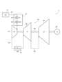
- FIG. 1 is a schematic configuration diagram of a power generation system according to one embodiment
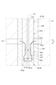
- FIG. FIG. 2 is a cross-sectional view showing the configuration of the steam valve according to the first embodiment in a state where the first valve body is in a closed state
- 3 is an enlarged view of area A of FIG. 2
- FIG. 3 is an enlarged view of area A of FIG. 2
- FIG. 3 is an enlarged view of area A of FIG. 2
- FIG. 3 is an enlarged view of area B of FIG. 2
- FIG. 3 is an enlarged view of area B of FIG. 2
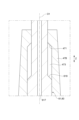
- FIG. 8 is a cross-sectional view showing the configuration of the steam valve according to the second embodiment in a state where both the first valve body and the second valve body are closed
- 6 is an enlarged view of region C of FIG.
- FIG. 6 is an enlarged view of region C of FIG. 5;
- FIG. 6 is an enlarged view of area D of FIG. 5;
- FIG. 6 is an enlarged view of area D of FIG. 5;
- FIG. 6 is an enlarged view of area E of FIG. 5;
- FIG. 6 is an enlarged view of area E of FIG. 5;
- FIG. 6 is an enlarged view of area E of FIG. 5;
- expressions that express shapes such as squares and cylinders do not only represent shapes such as squares and cylinders in a geometrically strict sense, but also include irregularities and chamfers to the extent that the same effect can be obtained. Shapes including parts etc. shall also be represented.
- the expressions “comprising”, “comprising”, “having”, “including”, or “having” one component are not exclusive expressions excluding the presence of other components.
- FIG. 1 is a schematic configuration diagram of a power generation system 1 according to one embodiment.
- the power generation system 1 includes a steam turbine 10 , a boiler 11 and a generator 26 .
- the steam turbine 10 is a turbine driven by the steam generated by the boiler 11.
- the steam turbine 10 is connected to a boiler 11 via a first steam supply pipe 12 and is driven by being supplied with high-pressure steam generated by burning fuel in the boiler 11 .
- a steam valve 14 for adjusting the flow rate of steam supplied to the steam turbine 10 is provided in the first steam supply pipe 12 .
- the structure of the steam valve 14, which will be described in detail later, includes a control valve 43 and a stop valve 45. As shown in FIG.
- a multi-stage turbine is exemplified as the steam turbine 10, and the steam turbine 10 includes a high-pressure steam turbine 31, an intermediate-pressure steam turbine 32, and a low-pressure steam turbine 33 from the upstream side with respect to the steam flow path.
- the high-pressure steam turbine 31 is driven by steam supplied from the first steam supply pipe 12 (high-pressure steam generated by the boiler 11).
- the steam that has finished work in the high pressure steam turbine 31 is supplied to the intermediate pressure steam turbine 32 via the second steam supply pipe 16 .
- a reheater 18 is provided in the second steam supply pipe 16 .
- the intermediate-pressure steam turbine 32 is driven by steam supplied from the second steam supply pipe 16 (steam that has finished work in the high-pressure steam turbine 31).
- the steam that has finished work in the intermediate pressure steam turbine 32 is supplied to the low pressure steam turbine 33 via the third steam supply pipe 25 .
- the low-pressure steam turbine 33 is driven by steam supplied from the third steam supply pipe 25 (steam that has finished work in the intermediate-pressure steam turbine 32).
- Each turbine (high-pressure steam turbine 31 , intermediate-pressure steam turbine 32 , and low-pressure steam turbine 33 ) that constitute the steam turbine 10 has a common rotating shaft 35 .
- a generator 26 is connected to the rotating shaft 35, and the generator 26 is driven by rotation of each turbine to generate power.
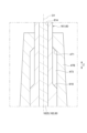
- FIG. 2 is a cross-sectional view showing the configuration of the steam valve 14 according to the first embodiment in a state where the first valve body 71 is in a closed state.
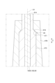
- 4A and 4B are enlarged views of region B of FIG. 2.
- FIG. 3A shows the state when the stop valve 45 starts to open after being fully closed
- FIGS. 3B and 4A show the state when the stop valve 45 is fully closed
- FIGS. 4B shows the state when the stop valve 45 is fully open.
- O1 is the axis of the valve stem 60 that constitutes the stop valve 45
- O2 is the control valve 43. It is the axis line of the valve stem 55 that constitutes.
- the direction in which the axes O1 and O2 extend (hereinafter referred to as "axial direction Z") is, for example, a substantially vertical direction.
- the steam valve 14 includes a valve body 41, a control valve 43, a stop valve 45, and actuators 46A and 46B.
- the valve body 41 has a flow path dividing portion 47 and a valve seat 48 .
- the channel partitioning portion 47 partitions the steam channel 52 and accommodates part of the control valve 43 (front end side) and part of the stop valve 45 (front end side).
- the steam flow path 52 has an inlet portion 52A and an outlet portion 52B.
- the inlet portion 52A is connected to the boiler 11 through one side of the first steam supply pipe 12, and high-pressure steam generated by the boiler 11 is introduced.
- the outlet portion 52B is connected to the high pressure steam turbine 31 via the other side of the first steam supply pipe 12 .
- the amount of steam supplied from the boiler 11 to the high-pressure steam turbine 31 via the first steam supply pipe 12 is controlled by the control valve 43 in the steam valve 14 provided in the first steam supply pipe 12 when the stop valve 45 is open. It is adjustable by controlling the degree of opening.
- the flow path dividing portion 47 includes a first guide member 47A and a second guide member 47B.
- 47 A of 1st guide members are provided so that the outer peripheral surface of the part which is not exposed to the steam flow path 52 among the valve stems 55 which comprise the control valve 43 may be covered.
- the first guide member 47A functions as a guide that guides the valve stem 55 in the axial direction Z.
- the second guide member 47B is provided so as to cover the outer peripheral surface of the rod-shaped portion 60B that constitutes the stop valve 45.
- the second guide member 47B functions as a guide that guides the valve stem 60 in the axial direction Z.
- the second guide member 47B protrudes into the steam flow path 52.
- FIG. 1st guide members are provided so that the outer peripheral surface of the part which is not exposed to the steam flow path 52 among the valve stems 55 which comprise the control valve 43 may be covered.
- the first guide member 47A functions as a guide that guides the valve stem 55 in the axial direction Z.
- the valve seat 48 is provided in the channel dividing portion 47 located in the middle of the steam channel 52 .
- the valve seat 48 has a ring shape centered on the axis O1, and is configured such that the axis of the valve seat 48 coincides with the axis O1. That is, the valve seat 48 has an opening centered on the axis O1.
- the valve seat 48 has a valve seat surface 48 a exposed to the steam flow path 52 .
- the valve seat surface 48a is, for example, a curved surface.
- the first valve body 71 constituting the stop valve 45 and the tip end 56A of the control valve main body 56 constituting the control valve 43 can come into contact with the valve seat surface 48a.
- control valve 43 The control valve 43 is arranged upstream of the position where the stop valve 45 is arranged in the steam flow direction.
- the control valve 43 has a valve stem 55 and a control valve main body 56 .
- the valve stem 55 extends in the axial direction Z, and the tip side thereof is arranged in the steam flow path 52 .
- the axis O ⁇ b>1 of the valve stem 55 is configured to coincide with the axis O ⁇ b>2 of the valve stem 55 of the stop valve 45 .
- the valve stem 55 is movable in the axial direction Z.
- the control valve main body 56 is provided on the tip side of the valve stem 55 .
- a portion of the control valve main body 56 located on the side of the valve seat 48 has a cylindrical shape and has a tip 56A capable of contacting the valve seat surface 48a of the valve seat 48 .
- the control valve 43 having such a configuration controls the distance between the tip 56A of the control valve main body 56 and the valve seat 48 by moving the valve rod 55 along the axial direction Z with the actuator 46A, thereby controlling the steam flow. It has a function of adjusting the flow rate of high-pressure steam supplied to the high-pressure steam turbine 31 according to the load of the turbine 10 .
- the stop valve 45 is arranged inside the control valve 43 .
- the stop valve 45 includes a valve stem 60 and a first valve body 71 .
- the valve stem 60 extends in the axial direction Z and has a distal end portion 60A and a rod-shaped portion 60B on the proximal side of the distal end portion 60A.
- the tip portion 60A has a shape that can be engaged with the first valve body 71 for fixing the first valve body 71 .
- the bar-shaped portion 60B extends along the axial direction Z.
- a proximal end of the rod-shaped portion 60B is connected to the actuator 46B.
- the valve stem 60 having the tip portion 60A and the rod-shaped portion 60B is divided into a first valve stem 61 and a second valve stem 62, as will be described in detail later.
- the valve stem 62 can move back and forth in the axial direction Z.
- the upper side in FIG. 2 is referred to as the distal side
- the lower side in FIG. 2 is referred to as the proximal side.
- the first valve stem 61 is located on the tip side of the valve stem 60 divided into two parts, and the first valve body 71 is fixed to the tip part 61A.
- the second valve stem 62 is positioned on the proximal end side of the valve stem 60 divided into two parts, and the actuator 46B is connected to the proximal end portion 62B.
- the proximal end 61B of the first valve stem 61 is connected to the distal end 62A of the second valve stem 62 .
- the proximal end portion 61B of the first valve stem 61 and the distal end portion 62A of the second valve stem 62 overlap in the axial direction Z.
- the base end portion 61B of the first valve rod 61 is configured such that the outer diameter of the region near the end on the base end side is smaller than the region on the tip side of the region. It has a small-diameter portion 611 formed in the .
- the base end portion 62B of the second valve stem 62 has a tubular portion 621 formed in a tubular shape so as to surround the outer periphery of the small diameter portion 611 of the first valve stem 61.
- the small diameter portion 611 of the first valve stem 61 and the tubular portion 621 of the second valve stem 62 are configured to be relatively movable in the axial direction Z. Further, a gap is provided between the outer peripheral surface of the small diameter portion 611 of the first valve stem 61 and the inner peripheral surface of the tubular portion 621 of the second valve stem 62. of steam can be circulated.
- the first valve stem 61 moves in the axial direction Z with the second valve stem 62 when the second valve stem 62 moves from the proximal side of the valve stem 60 toward the distal side. It has a pressing surface 613 at the time of the first valve opening that is pressed against.
- the second valve stem 62 presses the first valve-open pressing surface 613 . It has a second valve-open pressing surface 623 that presses in the axial direction Z. As shown in FIG.
- the first valve-open pressing surface 613 is formed at a position extending from the small-diameter portion 611 to a region on the distal side of the small-diameter portion 611 , for example, on the proximal side of the valve stem 60 . It is a conical inclined surface that expands the outer diameter of the first valve stem 61 as it goes from to the tip side.
- the second valve-open pressing surface 623 is formed at the distal end of the cylindrical portion 621, and for example, the cylindrical portion increases from the base end side toward the distal end side of the valve stem 60. It is a conical inclined surface that expands the inner diameter of the inner peripheral surface of 621 .
- the first pressure-opening pressure surface 613 and the second pressure-opening pressure surface 623 are formed so as to contact each other without a gap.
- the first valve-open pressing surface 613 and the second valve-opening pressing surface 623 may be spherical inclined surfaces instead of conical inclined surfaces.
- the first valve stem 61 has a first valve-close pressing surface 615 that is pressed in the axial direction Z by the second valve stem 62 when the stop valve 45 is fully closed.
- the second valve stem 62 has a second valve-closing pressure surface 625 that presses the first valve-closing pressure surface 615 in the axial direction Z when the stop valve 45 is fully closed.
- the first valve closing pressure surface 615 is formed at the proximal end portion of the small diameter portion 611 and extends from the distal end side to the proximal end side of the valve stem 60, for example.
- the second valve closing pressing surface 625 is formed on the base end side of the cylindrical portion 621, and for example, the pressure increases as the valve rod 60 moves from the tip end side to the base end side. It is a conical inclined surface that expands the inner diameter of the inner peripheral surface of the shaped portion 621 .
- the first pressure surface 615 when closing the valve and the second pressure surface 625 when closing the valve are formed so as to be in contact with each other without a gap.
- first valve-closed pressure surface 615 and the second valve-closed pressure surface 625 may be spherical inclined surfaces instead of conical inclined surfaces.
- the division position Pz of the first valve stem 61 and the second valve stem 62 in the axial direction Z is the first valve-opening pressing surface 613 and the second valve-opening pressing surface 623 . or a contact position between the first pressure surface 615 when closing the valve and the second pressure surface 625 when closing the valve.
- the first valve stem 61 and the second valve stem 62 move relatively in the axial direction Z so as to approach each other, and the first valve opening pressing surface 613 and the second valve opening pressing surface 613 move toward each other.
- the surface 623 abuts and is in close contact, and the first pressure surface 615 when closing the valve and the second pressure surface 625 when closing the valve are separated.
- valve stem 62 when the second valve stem 62 is driven toward the proximal side by the actuator 46B and the second valve stem 62 pulls the first valve stem 61 toward the proximal side, as shown in FIG. 45 is in the fully closed state, the first valve stem 61 and the second valve stem 62 move away from each other in the axial direction Z, and the first valve opening pressure surface 613 and the second valve opening pressure surface 613 move away from each other.
- the valve-time pressing surface 623 is separated, and the first valve-closing time pressing surface 615 and the second valve-closing time pressing surface 625 come into contact with each other and are in close contact with each other.
- the first valve stem 61 has a through hole 617 penetrating from the distal end 610a of the first valve stem 61 to the proximal end 610b.
- An end opening 617 a on the tip side of the through hole 617 faces the steam flow path 52 on the upstream side of the stop valve 45 .
- a proximal end opening 617 b of the through hole 617 faces an inner peripheral portion 621 a of the cylindrical portion 621 of the second valve stem 62 .
- first valve stem 61 is located on the distal end side of the region whose outer peripheral surface is covered with the second guide member 47B. It has a first inclined surface 619 that increases the outer diameter of the valve stem 60 (first valve stem 61) from the distal side toward the proximal side.
- the first inclined surface 619 is a conical inclined surface.
- the second guide member 47B has a first contact surface 471 that contacts the first inclined surface 619 of the first valve stem 61 when the stop valve 45 is fully opened, as shown in FIG. 4B.
- the first contact surface 471 is a conical inclined surface formed so that the inner diameter of the first contact surface 471 increases from the distal end side to the proximal end side.
- the first inclined surface 619 and the first contact surface 471 are formed so as to contact each other without a gap.
- the first inclined surface 619 and the first contact surface 471 may be spherical inclined surfaces instead of conical inclined surfaces.
- the stop valve 45 operates as follows. In the steam valve 14 , the stop valve 45 is opened before the control valve 43 is opened when the flow rate of steam is adjusted by the control valve 43 .
- the end opening 617 a on the tip side of the through-hole 617 faces the steam flow path 52 , the steam in the steam flow path 52 on the upstream side of the first valve body 71 flows through the through-hole 617 . It can flow into the inner peripheral portion 621a of the cylindrical portion 621 of the second valve stem 62 from the end opening 617b on the proximal side through the passage.
- the stop valve 45 is fully closed, as described above, since the first valve-closed pressure surface 615 and the second valve-closed pressure surface 625 are in contact with each other, the first valve-closed pressure surface Steam does not flow out to the tip side of 615 and the second pressing surface 625 when closing the valve.
- the stop valve 45 is fully opened.
- the first inclined surface 619 of the first valve stem 61 contacts the first contact surface 471 of the second guide member 47B without any gap, as shown in FIG. 4B.
- the first valve stem 61 is biased toward the distal end by the driving force of the actuator 46B. Therefore, the first inclined surface 619 and the first contact surface 471 are pressed against each other without a gap. Therefore, the pressure boundary 49 is formed by the first inclined surface 619 and the first contact surface 471 .
- the pressure boundary 49 separates the steam flow path 52 from the inner peripheral portion 473 of the second guide member 47B in terms of pressure.
- the split position Pz in the axial direction Z of the first valve stem 61 and the second valve stem 62 is separated from the steam flow path 52 in terms of pressure. Located outside the pressure boundary 49 .
- the first valve body 71 is fixed to the first valve stem 61, wear does not occur between the first valve body 71 and the first valve stem 61.
- the axial dividing position Pz between the first valve stem 61 and the second valve stem 62 is positioned outside the pressure boundary 49, the dividing position Pz is located in the steam flow path 52 where high-pressure steam may flow at high speed. is not exposed, wear at the dividing position Pz is effectively suppressed.
- the pressure boundary 49 is formed by the first inclined surface 619 and the first contact surface 471 .
- the pressure boundary 49 can be formed using the configuration for limiting the movement range of the valve stem 60 toward the distal end side, so the configuration of the steam valve 14 can be simplified.
- the first contact surface 471 is formed on the second guide member 47B, which is a cylindrical support member that slidably supports the valve stem 60.
- a pressure boundary 49 can be formed by the second guide member 47B, which is a support member for the valve stem, and the valve stem 60 (first valve stem 61).
- the first valve stem 61 has a first valve-open pressure surface 613 and the second valve stem 62 has a second valve-open pressure surface 623 .
- the second valve stem 62 moves the first valve stem 61 from the proximal side of the valve stem 60 toward the distal side. can be moved by
- the first valve stem 61 when the stop valve 45 is fully opened, is configured such that when the stop valve 45 is fully opened, the first contact surface 471 of the second guide member 47B and the second valve-open pressing surface of the second valve stem 62 623 and fixed to the second guide member 47B.
- the first valve stem 61 and the first valve body 71 fixed to the first valve stem 61 are fixed to the second guide member 47B. Vibration of the valve body 71 can be suppressed.
- the first valve stem 61 since the first valve stem 61 is fixed to the second guide member 47B, it is possible to effectively suppress wear at the contact portion between the first valve stem 61 and the second guide member 47B.
- the first valve stem 61 has a first valve-closing pressure surface 615 and the second valve stem 62 has a second valve-closing pressure surface 625 .
- the second valve stem 62 moves the first valve stem 61 from the distal end side of the valve stem 60 toward the proximal end side. can be moved by
- the first pressure surface 615 when closing the valve and the second pressure surface 625 when closing the valve are in close contact with each other, so that the pressure inside the steam flow path 52 is reduced. can be prohibited from flowing out to the outside through the through hole 617.
- the first valve closing pressing surface 615 and the second valve closing pressing surface 625 are separated from each other, and , the first valve-open pressing surface 613 and the second valve-open pressing surface 623 are separated from each other to allow the steam in the steam flow path 52 to flow out to the outside through the through hole 617 .
- the stop valve 45 starts to open from the fully closed state
- the steam acting on the stop valve 45 can be released to the outside through the through hole 617, and the pressure of the steam acting on the stop valve 45 can be reduced. . That is, the differential pressure between the upstream and downstream sides of the first valve body 71 is reduced, and the opening operation of the first valve body 71 is facilitated.
- FIG. 5 is a cross-sectional view showing the configuration of the steam valve 14 according to the second embodiment with both the first valve body 171 and the second valve body 172 closed.
- 6A and 6B are enlarged views of area C in FIG. 7A and 7B are enlarged views of area D in FIG. 8A and 8B are enlarged views of area E of FIG. 6A, 7A, and 8A show the state when the stop valve 45 is fully closed.
- FIG. 6B shows the open state of the second valve body 172 .
- FIG. 7B shows a state in which the stop valve 45 begins to open from the fully closed state and the second valve stem 162 begins to drive the first valve stem 161 .
- FIG. 8B shows the state when the stop valve 45 is fully open. Note that, in the following description, the same reference numerals as those of the steam valve 14 according to the first embodiment are assigned to the same configurations as those of the steam valve 14 according to the first embodiment, and detailed description may be omitted. .
- the first valve body 171 constituting the stop valve 45 and the tip end 56A of the control valve main body 56 constituting the control valve 43 can contact the valve seat surface 48a.
- the configuration of the control valve 43 is the same as that of the steam valve 14 according to the first embodiment.
- the stop valve 45 is arranged inside the control valve 43 in the same manner as the steam valve 14 according to the first embodiment.
- the stop valve 45 includes a valve stem 60 , a first valve body 171 and a second valve body 172 .
- the valve stem 60 extends in the axial direction Z and has a distal end portion 60A and a rod-shaped portion 60B on the proximal side of the distal end portion 60A.
- the tip portion 60A has a shape that can be engaged with the first valve body 171 for fixing the first valve body 171 .
- the bar-shaped portion 60B extends along the axial direction Z.
- a proximal end of the rod-shaped portion 60B is connected to the actuator 46B.
- the valve stem 60 having the tip end portion 60A and the rod-shaped portion 60B is divided into a first valve stem 161 and a second valve stem 162, which will be described in detail later.
- the valve stem 162 can move back and forth in the axial direction Z.
- the first valve stem 161 is a hollow valve stem located on the tip side of the split position in the axial direction Z of the valve stem 60 divided into two parts.
- a first valve body 171 is fixed to 161A.
- the first valve stem 161 has a valve stem insertion hole 614 that penetrates from the proximal end to the distal end of the first valve stem 161 and through which the later-described small diameter portion 162S of the second valve stem 162 is inserted.
- the distal end of the first valve stem 161 and the proximal surface of the first valve body 171 are connected, but the first valve stem 161 is connected to the first valve body. 1
- the valve body 171 may be penetrated in the axial direction Z.
- the second valve stem 162 includes a large-diameter portion 162L located on the proximal side of the split position in the axial direction Z of the valve stem 60 divided into two, and a It has a small diameter portion 162S located on the tip side of the Z division position and having a smaller diameter than the large diameter portion 162L.
- the small diameter portion 162 ⁇ /b>S is inserted through the valve stem insertion hole 614 of the first valve stem 161 .
- a tip portion 162a of the small diameter portion 162S protrudes to the tip side from the tip side surfaces of the first valve stem 161 and the first valve body 171, and the second valve body 172 is fixed thereto.
- An actuator 46B is connected to the base end portion 62B of the second valve stem 162 .
- the first valve stem 161 and the second valve stem 162 are configured to be relatively movable in the axial direction Z. That is, the small diameter portion 162S of the second valve stem 162 is slidably inserted in the axial direction Z into the valve stem insertion hole 614 of the first valve stem 161 covering the outer circumference of the small diameter portion 162S.
- the first valve stem 161 moves toward the distal end of the valve stem 60 when the second valve stem 162 moves from the proximal side to the distal side. It has a first valve-open pressing surface 616 that is pressed in the axial direction Z by the valve stem 162 .
- the second valve stem 162 presses the first valve-open pressing surface 616 . It has a second valve-open pressing surface 626 that presses in the axial direction Z.
- the first valve-open pressing surface 616 is formed on the proximal end portion 61B of the first valve stem 161, and is directed from the distal end side to the proximal end side of the valve stem 60, for example. It is a conical inclined surface that expands the inner diameter of the inner peripheral surface of the first valve stem 161 as it increases.
- the second valve-open pressing surface 626 is formed at the tip of the large-diameter portion 162L. It is a cone-shaped inclined surface that reduces the diameter. As shown in FIG. 7B, the first pressure-opening pressure surface 616 and the second pressure-opening pressure surface 626 are formed so as to be able to contact each other.
- first valve-open pressing surface 616 and the second valve-open pressing surface 626 may be spherical inclined surfaces instead of conical inclined surfaces.
- the split position Pz in the axial direction Z of the first valve stem 161 and the second valve stem 162 is the first valve-opening pressing surface 616 and the second valve-opening pressing surface 626 . It becomes a contact position with.
- first valve stem 161 and the second valve stem 162 are configured to be relatively movable in the axial direction Z.
- the first valve body 171 fixed to the first valve stem 161 and the second valve body 172 fixed to the second valve body 172 are configured to be relatively movable in the axial direction Z.
- the first valve body 171 is formed on the front end side surface of the first valve body 171, and the second valve body 172 abuts thereon. It has a contactable valve seat surface 74 .
- the first valve body 171 has a first valve body through hole 75 that penetrates the first valve body 171 in the axial direction Z. As shown in FIG. An opening 75 a on the tip end side of the first valve body through-hole 75 faces the steam flow path 52 on the upstream side of the first valve body 171 .
- a base end side opening 75 b of the first valve body through-hole 75 faces the steam flow path 52 downstream of the first valve body 171 .
- the second valve body 172 has a contact portion 77 that can contact the valve seat surface 74 of the first valve body 171 .
- the contact portion 77 is configured in a ring shape when viewed from the axial direction Z.
- An opening 75a on the distal end side of the first valve body through-hole 75 is formed radially inward of the contact portion 77 with respect to the axis O1 of the valve stem 60.
- the second valve body 172 is closed, that is, when the contact portion 77 is in close contact with the valve seat surface 74 of the first valve body 171, the steam passage 52 through which high-pressure steam flows is closed. Since the opening 75 a on the tip end side of the first valve body through-hole 75 is isolated from the first valve body through-hole 75 , high-pressure steam does not flow through the first valve body through-hole 75 .
- the first valve stem 61 and the second valve stem 62 move relatively in the axial direction Z so as to approach each other, and as shown in FIG.
- the valve seat surface 74 of the first valve body 171 and the contact portion 77 of the second valve body 172 are separated from each other as shown in FIG. 6B.
- the first valve-opening pressing surface 616 and the second valve-opening pressing surface 626 are separated, and the first The valve seat surface 74 of the valve body 171 and the contact portion 77 of the second valve body 172 are in contact with each other.
- the driving force by which the actuator 46B drives the second valve stem 162 toward the proximal side is generated by the contact portion 77 of the second valve body 172 pressing the valve seat surface 74 of the first valve body 171 toward the proximal side. By doing so, it is transmitted to the first valve body 171 and the first valve stem 161 .
- valve seat surface 74 of the first valve body 171 is shown in FIG. 6B. and the contact portion 77 of the second valve body 172 are separated from each other.
- the first valve stem 161 is located on the tip side of the valve stem 60 in the region whose outer peripheral surface is covered with the second guide member 47B. It has a first inclined surface 619 that increases the outer diameter of the valve stem 60 (first valve stem 161) from the distal side toward the proximal side.
- the first inclined surface 619 is a conical inclined surface.
- the second guide member 47B has a first contact surface 471 that contacts the first inclined surface 619 of the first valve stem 161 when the stop valve 45 is fully opened, as shown in FIG. 8B.
- the first contact surface 471 is a conical inclined surface formed so that the inner diameter of the first contact surface 471 increases from the distal end side to the proximal end side.
- the first inclined surface 619 and the first contact surface 471 are formed so as to contact each other without a gap.
- the first inclined surface 619 and the first contact surface 471 may be spherical inclined surfaces instead of conical inclined surfaces.
- the stop valve 45 operates as follows. In the steam valve 14 , the stop valve 45 is opened before the control valve 43 is opened when the flow rate of steam is adjusted by the control valve 43 .
- the high-pressure steam that has flowed into the opening 75 a on the distal end side of the first valve body through hole 75 is led out to the steam flow path 52 from the opening 75 b on the proximal side of the first valve body through hole 75 .
- the differential pressure between the upstream and downstream sides of the first valve body 171 is reduced, and the subsequent opening operation of the first valve body 171 is facilitated.
- the stop valve 45 is fully opened.
- the first inclined surface 619 of the first valve stem 161 contacts the first contact surface 471 of the second guide member 47B without any gap, as shown in FIG. 8B. This restricts the movement of the first valve stem 161 and the first valve body 171 toward the distal end side.
- the first valve stem 161 is biased toward the distal end by the driving force of the actuator 46B. Therefore, the first inclined surface 619 and the first contact surface 471 are pressed against each other without a gap. Therefore, the pressure boundary 49 is formed by the first inclined surface 619 and the first contact surface 471 .
- the pressure boundary 49 separates the steam flow path 52 from the inner peripheral portion 473 of the second guide member 47B in terms of pressure.
- the split position Pz in the axial direction Z of the first valve stem 161 and the second valve stem 162 is separated from the steam flow path 52 in terms of pressure. Located outside the pressure boundary 49 .
- the first valve body 171 is fixed to the first valve stem 161
- wear does not occur between the first valve body 171 and the first valve stem 161.
- the dividing position Pz is located in the steam flow path 52 where high-pressure steam may flow at high speed. is not exposed, wear at the dividing position Pz is effectively suppressed.
- the pressure boundary 49 is formed by the first inclined surface 619 and the first contact surface 471 .
- the pressure boundary 49 can be formed using the configuration for limiting the movement range of the valve stem 60 toward the distal end side, so the configuration of the steam valve 14 can be simplified.
- the first contact surface 471 is formed on the second guide member 47B, which is a cylindrical support member that slidably supports the valve stem 60.
- a pressure boundary 49 can be formed by the second guide member 47B, which is a support member for the valve stem, and the valve stem 60 (first valve stem 161).
- the first valve stem 161 has a first valve-open pressing surface 616
- the second valve stem 162 has a second valve-opening pressing surface 626 .
- the first valve stem 161 when the stop valve 45 is fully opened, is configured such that when the stop valve 45 is fully opened, the first contact surface 471 of the second guide member 47B and the second valve-open pressing surface of the second valve stem 162 626 and fixed to the second guide member 47B.
- the first valve stem 161 and the first valve body 171 fixed to the first valve stem 161 are fixed to the second guide member 47B. Vibration of the valve body 171 can be suppressed.
- the first valve stem 161 since the first valve stem 161 is fixed to the second guide member 47B, it is possible to effectively suppress wear at the contact portion between the first valve stem 161 and the second guide member 47B.
- the stop valve 45 has the second valve body 172 fixed to the tip portion 162 a of the second valve stem 162 .
- the first valve body 171 functions as a valve seat for the second valve body 172 and is formed with a first valve body through hole 75 into which steam flows when the second valve body 172 is opened.
- the steam acting on the stop valve 45 can escape to the outside through the first valve body through-hole 75 by opening the second valve body 172 , and the pressure of the steam acting on the stop valve 45 can be reduced. That is, the differential pressure between the upstream and downstream sides of the first valve body 171 is reduced, and the opening operation of the first valve body 71 is facilitated.
- since the second valve stem 162 and the second valve body 172 are fixed, no wear occurs between the second valve body 172 and the second valve stem 162. .
- the first valve body through-hole 75 is formed in the first valve body 171
- the amount of steam leaking from the gap between the control valve 43 and the valve seat 48 is relatively small. Even if there are many, the differential pressure between the upstream and downstream sides of the first valve body 171 can be effectively reduced.
- the first valve body 171 moves the valve stem 60 by the second valve body 172 when the second valve stem 162 moves from the distal end side of the valve stem 60 toward the proximal end side. It is configured to be pressed from the distal end side toward the proximal end side of the valve stem 60 and move together with the first valve stem 161 from the distal end side toward the proximal end side of the valve stem 60 . As a result, the first valve body 171 and the first valve stem 161 can be moved from the distal end side of the valve stem 60 toward the proximal end side by the second valve body 172 .
- the first valve body 171 when the stop valve 45 is fully closed, the first valve body 171 is clamped and fixed between the valve seat 48 of the valve body 41 and the second valve body 172. Leakage of steam from between the first valve body 171 and the valve seat 48 of the valve body 41 can be effectively prevented.
- the overlapping length in the axial direction Z of the first valve stem 161 and the small diameter portion 162S of the second valve stem 162 has a relatively large range of selection from a functional point of view. Since it is large, it is easy to optimize from the viewpoints of the wear soundness of the stop valve 45, the vibration soundness of the stop valve 45, and the drive soundness of the stop valve 45. It should be noted that the position in the axial direction Z where the first valve-opening pressing surface 616 and the second valve-opening pressing surface 626 are provided is not necessarily in the vicinity of a system for recovering leaked steam such as the high-pressure stem leak system 81 or the like. good too.
- the first valve-opening pressing surface 616 and the second valve-open pressing surface 626 may be located in the atmosphere open portion. That is, if the steam valve 14 is configured so that steam does not leak from between the first valve-opening pressing surface 616 and the second valve-opening pressing surface 626 to the outside, the first valve stem 161 and the second The length in which the small diameter portion 162S of the two valve stems 162 overlaps in the axial direction Z may be any length.
- the first inclined surface 619 and the first contact surface 471 form the pressure boundary 49 . Therefore, the gap between the inner diameter of the valve stem insertion hole 614 of the first valve stem 161 and the outer diameter of the small-diameter portion 162S of the second valve stem 162 can be made relatively large, and driving soundness such as suppression of stick-slip can be improved. Easy to keep.
- the steam valve 14 is arranged to face the stop valve 45 in the axial direction Z, and is positioned outside the position of the valve seat 48 with which the first valve bodies 71 and 171 abut. It has a control valve 43 that can come into contact with a valve seat 48 . As a result, in the steam valve 14 in which the control valve 43 is arranged outside the stop valve 45 , it is possible to effectively suppress the wear of the steam valve 14 .
- a power generation system 1 includes the steam valve 14 according to some embodiments described above, a boiler 11 that generates steam, a steam turbine 10 that is driven by the steam, and the boiler 11 and the steam turbine 10. and a steam supply pipe (first steam supply pipe 12 ) that is connected to supply steam to the steam turbine 10 .
- a steam valve 14 according to some embodiments is provided in a steam supply pipe (first steam supply pipe 12).
- the present disclosure is not limited to the above-described embodiments, and includes modifications of the above-described embodiments and modes in which these modes are combined as appropriate.
- the second guide member 47B may not protrude into the steam flow path 52 .
- the first contact surface 471 that contacts the first inclined surface 619 of the first valve stem 61, 161 when the stop valve 45 is fully opened is, for example, the flow path dividing portion 47 (valve casing ) or a through bush attached to the flow path dividing portion 47, the guide member 47B may be provided on a member other than the second guide member 47B.
- the steam valve 14 includes a steam flow path 52 through which steam flows, and a valve body 41 having a valve seat 48 provided in the middle of the steam flow path 52 and having an opening, A valve stem 60 that extends in the axial direction Z along which the axes O1 and O2 extend and can move back and forth in the axial direction Z, and a valve stem 60 that is fixed to the tip portion 60A and abuts against the valve seat 48, thereby forming a steam flow path. and a stop valve 45 having a first valve body 71 , 171 closing 52 .
- the valve stem 60 is divided into first valve stems 61 and 161 to which the first valve bodies 71 and 171 are fixed and second valve stems 62 and 162 different from the first valve stems 61 and 161 .
- a division position Pz in the axial direction Z of the first valve stems 61 , 161 and the second valve stems 62 , 162 is located outside the pressure boundary 49 that is pressure-separated from the steam flow path 52 .
- the gap between the first valve body 71, 171 and the first valve stem 61, 161 is Since the division position Pz in the axial direction Z of the first valve stems 61, 161 and the second valve stems 62, 162 is positioned outside the pressure boundary 49, high-pressure steam flows at high speed. Since the dividing position Pz is not exposed to the steam flow path 52, which may occur, abrasion at the dividing position Pz is effectively suppressed.
- the valve stem 60 has a first inclined surface that increases the outer diameter of the valve stem 60 from the distal end side to the proximal end side of the valve stem 60. 619.
- the steam valve 14 according to at least one embodiment of the present disclosure preferably includes a mating member (second guide member 47B) having a first contact surface 471 that contacts the first inclined surface 619 when the stop valve 45 is fully opened.
- the pressure boundary 49 is preferably formed by the first inclined surface 619 and the first contact surface 471 .
- the pressure boundary 49 can be formed using the configuration for limiting the movement range of the valve stem 60 toward the tip side, so the configuration of the steam valve 14 can be simplified.
- the mating member is a cylindrical support member (second guide member 47B) that slidably supports the valve stem 60. ).
- the support member (second guide member 47B) of the valve stem 60 and the valve stem 60 can form the pressure boundary 49 .
- the first valve stem 61, 161 and the second valve stem 62, 162 extend from the proximal side to the distal side of the valve stem 60. It is preferable to have first valve-open pressing surfaces 613 and 616 that are pressed in the axial direction Z by the second valve stems 62 and 162 when moving toward. The second valve stems 62 and 162 axially press the first valve-open pressing surfaces 613 and 616 when the second valve stems 62 and 162 move from the proximal side to the distal side of the valve stem 60 . It is preferable to have the second valve-open pressing surfaces 623 and 626 .
- the second valve stems 62, 162 allow the first valve stem 61 to , 161 can be moved from the proximal side of the valve stem 60 toward the distal side.
- the first valve stem 61, 161 has the first contact surface 471 when the stop valve 45 is fully opened and the second valve-open pressure surfaces 623, 626. and fixed to the mating member (second guide member 47B).
- the first valve stems 61 and 161 and the first valve bodies 71 and 171 fixed to the first valve stems 61 and 161 are connected to the mating member (the second guide). Since it is fixed to the member 47B), the vibration of the first valve stems 61, 161 and the first valve bodies 71, 171 can be suppressed. In addition, since the first valve stems 61 and 161 are fixed to the mating member (second guide member 47B), the wear at the contact portion between the first valve stems 61 and 161 and the mating member (second guide member 47B) is effectively reduced. can be effectively suppressed.
- the first valve stem 61 may have a through hole 617 penetrating from the distal end to the proximal end of the first valve stem 61 .
- the stop valve 45 When the stop valve 45 is fully opened, the first valve-open pressing surface 613 and the second valve-open pressing surface 623 abut against each other, thereby preventing the steam in the steam flow path 52 from flowing out to the outside through the through hole 617. do it.
- the first valve stem 61 is pressed in the axial direction Z by the second valve stem 62 when the stop valve 45 is fully closed. It is preferable to have the first pressure surface 615 when the valve is closed.
- the second valve stem 62 preferably has a second valve-closing pressure surface 625 that axially presses the first valve-closing pressure surface 615 when the stop valve 45 is fully closed.
- the second valve stem 62 moves the first valve stem 61 to the distal end of the valve stem 60 . It can be moved from the side to the proximal side.
- the first valve stem 61 may have a through hole 617 penetrating from the distal end of the first valve stem 61 to the proximal end.
- the stop valve 45 When the stop valve 45 is fully closed, the first valve closing pressure surface 615 and the second valve closing pressure surface 625 abut against each other to prevent the steam in the steam flow path 52 from flowing out to the outside through the through hole 617. should be prohibited.
- the stop valve 45 when the stop valve 45 starts to open from the fully closed state, the steam in the through hole 617 can be released to the outside.
- the steam acting on the valve 45 can be released to the outside to reduce the pressure of the steam acting on the stop valve 45 .
- the stop valve 45 when the stop valve 45 is fully closed, steam can be prohibited from flowing out to the outside through the through hole 617 .
- the first valve stem 161 penetrates from the proximal end to the distal end of the first valve stem 161, and the second valve stem 162 (small diameter portion 162S) is preferably provided with a valve stem insertion hole 614.
- the second valve stem 162 (small diameter portion 162 S) is preferably inserted through the valve stem insertion hole 614 .
- the stop valve 45 preferably has a second valve body 172 fixed to the tip portion 162 a of the second valve stem 162 .
- the first valve body 171 functions as a valve seat for the second valve body 172, and is preferably formed with a first valve body through hole 75 through which steam flows when the second valve body 172 is opened.
- the steam acting on the stop valve 45 is released to the outside through the first valve body through-hole 75 by opening the second valve body 172, and the pressure of the steam acting on the stop valve 45 is increased. can be reduced. Further, according to the configuration (10) above, since the second valve stem 162 and the second valve body 172 are fixed, no wear occurs between the second valve body 172 and the second valve stem 162 .
- the first valve body 171 moves toward the proximal side. It is preferable that the valve body 172 presses the valve stem 60 from the distal side toward the proximal side and moves together with the first valve stem 161 from the distal side toward the proximal side of the valve stem 60 .
- the first valve body 171 and the first valve stem 161 are movable by the second valve body 172 from the distal end side of the valve stem 60 toward the proximal end side. Further, according to the configuration (11) above, when the stop valve 45 is fully closed, the first valve body 171 is held between the valve seat 48 of the valve body 41 and the second valve body 172 and fixed. It is possible to effectively prevent leakage of steam from between the valve body 171 and the valve seat 48 of the valve main body 41 .
- the stop valve 45 is opposed to the stop valve 45 in the axial direction Z, and the first valve body 71, 171 is in contact with the stop valve 45. It is preferable to have a control valve 43 that can contact the valve seat 48 at a position outside the position of the valve seat 48 .
- the power generation system 1 includes the steam valve 14 configured in any one of (1) to (12) above, the boiler 11 that generates steam, and the steam driven by the steam.
- a turbine 10 and a steam supply pipe (first steam supply pipe 12 ) that connects the boiler 11 and the steam turbine 10 and supplies steam to the steam turbine 10 .
- the steam valve 14 is provided in the steam supply pipe (first steam supply pipe 12).
- the power generation system 1 since the power generation system 1 includes the steam valve 14 capable of suppressing the wear of the stop valve 45, it is possible to reduce the maintenance frequency of the steam valve 14. Therefore, the power generation system 1 It is possible to improve the moving efficiency of
Landscapes
- Engineering & Computer Science (AREA)
- General Engineering & Computer Science (AREA)
- Mechanical Engineering (AREA)
- Chemical & Material Sciences (AREA)
- Combustion & Propulsion (AREA)
- Lift Valve (AREA)
- Control Of Turbines (AREA)
Priority Applications (5)
| Application Number | Priority Date | Filing Date | Title |
|---|---|---|---|
| DE112022002451.8T DE112022002451T5 (de) | 2022-02-01 | 2022-12-13 | Dampfventil und energieerzeugungssystem |
| KR1020237034521A KR102925370B1 (ko) | 2022-02-01 | 2022-12-13 | 증기 밸브, 및 발전 시스템 |
| CN202280029372.XA CN117178132A (zh) | 2022-02-01 | 2022-12-13 | 蒸汽阀及发电系统 |
| US18/292,063 US12510186B2 (en) | 2022-02-01 | 2022-12-13 | Steam valve and power generation system |
| JP2023578404A JP7654120B2 (ja) | 2022-02-01 | 2022-12-13 | 蒸気弁、及び発電システム |
Applications Claiming Priority (2)
| Application Number | Priority Date | Filing Date | Title |
|---|---|---|---|
| JP2022014352 | 2022-02-01 | ||
| JP2022-014352 | 2022-02-01 |
Publications (1)
| Publication Number | Publication Date |
|---|---|
| WO2023149088A1 true WO2023149088A1 (ja) | 2023-08-10 |
Family
ID=87552171
Family Applications (1)
| Application Number | Title | Priority Date | Filing Date |
|---|---|---|---|
| PCT/JP2022/045761 Ceased WO2023149088A1 (ja) | 2022-02-01 | 2022-12-13 | 蒸気弁、及び発電システム |
Country Status (6)
| Country | Link |
|---|---|
| US (1) | US12510186B2 (https=) |
| JP (1) | JP7654120B2 (https=) |
| KR (1) | KR102925370B1 (https=) |
| CN (1) | CN117178132A (https=) |
| DE (1) | DE112022002451T5 (https=) |
| WO (1) | WO2023149088A1 (https=) |
Families Citing this family (1)
| Publication number | Priority date | Publication date | Assignee | Title |
|---|---|---|---|---|
| CN121363493B (zh) * | 2025-12-22 | 2026-03-24 | 北京宇航推进科技有限公司 | 泄出阀、火箭发动机及火箭 |
Citations (7)
| Publication number | Priority date | Publication date | Assignee | Title |
|---|---|---|---|---|
| JPS53105129U (https=) * | 1977-01-31 | 1978-08-24 | ||
| JPS60237101A (ja) * | 1984-05-08 | 1985-11-26 | Toshiba Corp | 蒸気弁監視装置 |
| JP2010121523A (ja) * | 2008-11-19 | 2010-06-03 | Toshiba Corp | 蒸気弁 |
| JP2015200232A (ja) * | 2014-04-08 | 2015-11-12 | 株式会社東芝 | 蒸気弁 |
| WO2017200067A1 (ja) * | 2016-05-20 | 2017-11-23 | 三菱日立パワーシステムズ株式会社 | バルブ及び蒸気タービン設備 |
| JP2018131962A (ja) * | 2017-02-15 | 2018-08-23 | 三菱日立パワーシステムズ株式会社 | 蒸気弁及び蒸気タービン設備 |
| JP2019100243A (ja) * | 2017-11-30 | 2019-06-24 | 三菱日立パワーシステムズ株式会社 | 蒸気弁および蒸気タービン |
Family Cites Families (4)
| Publication number | Priority date | Publication date | Assignee | Title |
|---|---|---|---|---|
| JP2014070513A (ja) | 2012-09-28 | 2014-04-21 | Hitachi Ltd | 蒸気タービン用蒸気弁 |
| JP2014237101A (ja) * | 2013-06-10 | 2014-12-18 | 日揮株式会社 | 内部観察窓 |
| JP6666280B2 (ja) * | 2017-02-15 | 2020-03-13 | 三菱日立パワーシステムズ株式会社 | 開閉弁、及び蒸気タービン |
| US20220014352A1 (en) | 2020-07-13 | 2022-01-13 | Rearden Ventures, Inc. | Smart prompts, ai-based digital representative, and multi-object steganographic encryption |
-
2022
- 2022-12-13 KR KR1020237034521A patent/KR102925370B1/ko active Active
- 2022-12-13 CN CN202280029372.XA patent/CN117178132A/zh active Pending
- 2022-12-13 US US18/292,063 patent/US12510186B2/en active Active
- 2022-12-13 WO PCT/JP2022/045761 patent/WO2023149088A1/ja not_active Ceased
- 2022-12-13 JP JP2023578404A patent/JP7654120B2/ja active Active
- 2022-12-13 DE DE112022002451.8T patent/DE112022002451T5/de active Pending
Patent Citations (7)
| Publication number | Priority date | Publication date | Assignee | Title |
|---|---|---|---|---|
| JPS53105129U (https=) * | 1977-01-31 | 1978-08-24 | ||
| JPS60237101A (ja) * | 1984-05-08 | 1985-11-26 | Toshiba Corp | 蒸気弁監視装置 |
| JP2010121523A (ja) * | 2008-11-19 | 2010-06-03 | Toshiba Corp | 蒸気弁 |
| JP2015200232A (ja) * | 2014-04-08 | 2015-11-12 | 株式会社東芝 | 蒸気弁 |
| WO2017200067A1 (ja) * | 2016-05-20 | 2017-11-23 | 三菱日立パワーシステムズ株式会社 | バルブ及び蒸気タービン設備 |
| JP2018131962A (ja) * | 2017-02-15 | 2018-08-23 | 三菱日立パワーシステムズ株式会社 | 蒸気弁及び蒸気タービン設備 |
| JP2019100243A (ja) * | 2017-11-30 | 2019-06-24 | 三菱日立パワーシステムズ株式会社 | 蒸気弁および蒸気タービン |
Also Published As
| Publication number | Publication date |
|---|---|
| US20240328538A1 (en) | 2024-10-03 |
| DE112022002451T5 (de) | 2024-02-29 |
| JP7654120B2 (ja) | 2025-03-31 |
| JPWO2023149088A1 (https=) | 2023-08-10 |
| US12510186B2 (en) | 2025-12-30 |
| KR20230154321A (ko) | 2023-11-07 |
| CN117178132A (zh) | 2023-12-05 |
| KR102925370B1 (ko) | 2026-02-09 |
Similar Documents
| Publication | Publication Date | Title |
|---|---|---|
| CN100365338C (zh) | 流体控制阀 | |
| JP6718306B2 (ja) | バルブ及び蒸気タービン設備 | |
| JP6058028B2 (ja) | 蒸気弁及び蒸気タービン | |
| WO2020138307A1 (ja) | 蒸気弁、及び発電システム | |
| KR102316923B1 (ko) | 터빈 웨이스트게이트 | |
| JP5193299B2 (ja) | 圧力バランス式の制御弁を有する燃料噴射弁 | |
| US9593690B2 (en) | Turbocharger with an annular rotary bypass valve | |
| KR102363772B1 (ko) | 터빈 웨이스트게이트 조립체 | |
| CN101680413A (zh) | 用于燃料喷射阀的控制阀 | |
| WO2023149088A1 (ja) | 蒸気弁、及び発電システム | |
| JP2011047290A (ja) | Egrバルブ | |
| CA1041982A (en) | Combined stop and control valve | |
| JP2006512533A (ja) | 2つの同軸的な弁ニードルを備えた燃料噴射弁 | |
| JP2009275646A (ja) | 燃料噴射ノズル | |
| JP6713826B2 (ja) | 親子弁及びその閉弁方法並びに蒸気タービン設備 | |
| JP5021731B2 (ja) | 燃料インジェクター | |
| JP4648857B2 (ja) | 蒸気加減弁 | |
| US7871021B2 (en) | Injection nozzle | |
| JP2023105851A (ja) | 蒸気弁、及び、発電システム | |
| WO2024034368A1 (ja) | 蒸気弁及び発電システム | |
| JP2004169699A (ja) | 内燃機関に用いられる燃料噴射弁 | |
| JP2007024040A (ja) | 噴射ノズル | |
| RU2763342C1 (ru) | Двухзапорный клапан | |
| WO2026053024A1 (en) | Gas injector | |
| JP2021080931A (ja) | 蒸気弁及び蒸気タービン設備並びに蒸気弁の組立て方法 |
Legal Events
| Date | Code | Title | Description |
|---|---|---|---|
| 121 | Ep: the epo has been informed by wipo that ep was designated in this application |
Ref document number: 22924992 Country of ref document: EP Kind code of ref document: A1 |
|
| ENP | Entry into the national phase |
Ref document number: 20237034521 Country of ref document: KR Kind code of ref document: A |
|
| WWE | Wipo information: entry into national phase |
Ref document number: 1020237034521 Country of ref document: KR |
|
| WWE | Wipo information: entry into national phase |
Ref document number: 2023578404 Country of ref document: JP |
|
| WWE | Wipo information: entry into national phase |
Ref document number: 202317081106 Country of ref document: IN |
|
| WWE | Wipo information: entry into national phase |
Ref document number: 112022002451 Country of ref document: DE |
|
| WWE | Wipo information: entry into national phase |
Ref document number: 18292063 Country of ref document: US |
|
| 122 | Ep: pct application non-entry in european phase |
Ref document number: 22924992 Country of ref document: EP Kind code of ref document: A1 |
|
| WWG | Wipo information: grant in national office |
Ref document number: 18292063 Country of ref document: US |