WO2023148829A1 - 無線通信方法及び無線通信システム - Google Patents
無線通信方法及び無線通信システム Download PDFInfo
- Publication number
- WO2023148829A1 WO2023148829A1 PCT/JP2022/003881 JP2022003881W WO2023148829A1 WO 2023148829 A1 WO2023148829 A1 WO 2023148829A1 JP 2022003881 W JP2022003881 W JP 2022003881W WO 2023148829 A1 WO2023148829 A1 WO 2023148829A1
- Authority
- WO
- WIPO (PCT)
- Prior art keywords
- communication
- wireless communication
- node
- data
- unit
- Prior art date
Links
- 238000004891 communication Methods 0.000 title claims abstract description 248
- 238000000034 method Methods 0.000 title claims abstract description 15
- 239000000872 buffer Substances 0.000 claims abstract description 20
- 230000005540 biological transmission Effects 0.000 claims abstract description 19
- 238000010586 diagram Methods 0.000 description 13
- 230000006870 function Effects 0.000 description 9
- 238000012545 processing Methods 0.000 description 6
- 238000012544 monitoring process Methods 0.000 description 5
- 238000010295 mobile communication Methods 0.000 description 2
- 238000012986 modification Methods 0.000 description 2
- 230000004048 modification Effects 0.000 description 2
- 238000012546 transfer Methods 0.000 description 2
- 240000007594 Oryza sativa Species 0.000 description 1
- 235000007164 Oryza sativa Nutrition 0.000 description 1
- 230000003044 adaptive effect Effects 0.000 description 1
- 239000012141 concentrate Substances 0.000 description 1
- 238000011161 development Methods 0.000 description 1
- 235000009566 rice Nutrition 0.000 description 1
Images


Classifications
-
- H—ELECTRICITY
- H04—ELECTRIC COMMUNICATION TECHNIQUE
- H04W—WIRELESS COMMUNICATION NETWORKS
- H04W40/00—Communication routing or communication path finding
- H04W40/02—Communication route or path selection, e.g. power-based or shortest path routing
- H04W40/12—Communication route or path selection, e.g. power-based or shortest path routing based on transmission quality or channel quality
-
- H—ELECTRICITY
- H04—ELECTRIC COMMUNICATION TECHNIQUE
- H04W—WIRELESS COMMUNICATION NETWORKS
- H04W40/00—Communication routing or communication path finding
- H04W40/34—Modification of an existing route
-
- H—ELECTRICITY
- H04—ELECTRIC COMMUNICATION TECHNIQUE
- H04W—WIRELESS COMMUNICATION NETWORKS
- H04W84/00—Network topologies
- H04W84/02—Hierarchically pre-organised networks, e.g. paging networks, cellular networks, WLAN [Wireless Local Area Network] or WLL [Wireless Local Loop]
- H04W84/04—Large scale networks; Deep hierarchical networks
- H04W84/06—Airborne or Satellite Networks
-
- Y—GENERAL TAGGING OF NEW TECHNOLOGICAL DEVELOPMENTS; GENERAL TAGGING OF CROSS-SECTIONAL TECHNOLOGIES SPANNING OVER SEVERAL SECTIONS OF THE IPC; TECHNICAL SUBJECTS COVERED BY FORMER USPC CROSS-REFERENCE ART COLLECTIONS [XRACs] AND DIGESTS
- Y02—TECHNOLOGIES OR APPLICATIONS FOR MITIGATION OR ADAPTATION AGAINST CLIMATE CHANGE
- Y02D—CLIMATE CHANGE MITIGATION TECHNOLOGIES IN INFORMATION AND COMMUNICATION TECHNOLOGIES [ICT], I.E. INFORMATION AND COMMUNICATION TECHNOLOGIES AIMING AT THE REDUCTION OF THEIR OWN ENERGY USE
- Y02D30/00—Reducing energy consumption in communication networks
- Y02D30/70—Reducing energy consumption in communication networks in wireless communication networks
Definitions
- the present invention relates to a wireless communication method and a wireless communication system.
- Super coverage means expanding the service area to places where the cost of laying existing base stations is high, such as mountains, seas, and air, or where it is difficult to lay base stations.
- there is a need for national resilience against natural disasters, etc. and there is a demand for a communication system that is resistant to terrestrial disasters.
- Non-Patent Document 1 In order to realize such a wireless communication system, geostationary satellites, medium earth orbit (MEO), low earth orbit (LEO), high altitude pseudosatellites (HAPS), Unmanned Aerial Vehicles (UAVs) and non-terrestrial networks (NTNs) using drones and the like are attracting attention (see, for example, Non-Patent Document 1).
- MEO medium earth orbit
- LEO low earth orbit
- HAPS high altitude pseudosatellites
- UAVs Unmanned Aerial Vehicles
- NTNs non-terrestrial networks
- Satellites and HAPS connect communication links to form a network, and are connected to terrestrial mobile networks via terrestrial base stations. Satellites and HAPS carry mobile base station functionality.
- the traffic packets sent by the terminal station are transferred to the satellite and HAPS connected to the ground base station by the routing function, and sent to the Internet network. Packets transmitted from the Internet network to other terminal stations are similarly processed by the routing function.
- a method of determining the route by calculating the cost value for each link is being studied. For example, when determining a communication route in NTN, the route with the smallest sum of cost values calculated for each communication link is selected as the communication route.
- An object of the present invention is to provide a wireless communication method and a wireless communication system capable of performing communication.
- a wireless communication method is a wireless communication method for transmitting data via a wireless communication path switchable by a plurality of moving node stations equipped with transmission buffers, wherein each of the node stations transmits data.
- a radio communication system is a radio communication system in which a plurality of moving node stations having transmission buffers transmit data via switchable radio communication paths, wherein each of the node stations an acquisition unit that acquires correspondence information corresponding to the amount of data transmitted by each time a communication situation fluctuates, and based on each of the correspondence information acquired by the acquisition unit, per unit link speed between the plurality of nodes a changing unit for changing the cost value of the above; a calculating unit for calculating the cost value between the plurality of node stations using the cost value changed by the changing unit; and a determination unit that determines the route as the communication route.
- wireless communication can be performed efficiently while reducing the concentration of traffic on a specific communication path.
- FIG. 1 is a diagram illustrating a configuration example of a wireless communication system according to an embodiment
- FIG. FIG. 4 is a diagram showing a configuration example of a node station; It is a figure which shows the structural example of a route control part.
- 4 is a flow chart showing a first operation example of the wireless communication system according to one embodiment; It is a figure which shows the 1st operation example of the radio
- 9 is a flow chart showing a second operation example of the wireless communication system according to one embodiment
- FIG. 7 is a diagram showing a second operation example of the wireless communication system according to one embodiment
- 9 is a flowchart showing a third operation example of the wireless communication system according to one embodiment;
- FIG. 11 is a flow chart showing a fourth operation example of the wireless communication system according to one embodiment
- FIG. FIG. 12 is a diagram showing a fourth operation example of the wireless communication system according to one embodiment
- FIG. 5 is a diagram illustrating a configuration of a modification of the network control device in the wireless communication system according to one embodiment
- It is a figure which shows the structural example of a radio
- FIG. 12 is a diagram showing a configuration example of the radio communication system 1.
- a wireless communication system 1 includes, for example, base stations (terrestrial base stations) 2-1 to 2-5 and node stations 3-1 to 3-5, and a plurality of terminal stations (terrestrial terminals). stations) 4-1 to 4-4 are each connectable.
- the node stations 3-1 to 3-5 are wireless communication devices such as unmanned aerial vehicles or satellites that move on the ground, each having a mobile base station function, for example, connecting communication links a to f to transmit NTN. Configure.
- the wireless communication system 1 selects the route that minimizes the sum of the cost values calculated for each communication link as the communication route.
- the cost value is calculated by the following formula (1).
- the link speed and link delay are fixed values set by the user.
- the wireless communication system 1 selects a faster communication link.
- the radio communication system 1 selects a communication link with a lower delay.
- the wireless communication system 1 is configured so that the cost value is calculated using the above equation (1), and a high-speed and low-delay communication link can be easily selected as a communication route.
- the cost value of communication link a is "1"
- the cost value of communication link b is "2”
- the cost value of communication link c is "4"
- the cost value of communication link d is "4". 1”
- the cost value of communication link e is "30”
- the cost value of communication link f is "30”.
- the radio communication system 1 has a communication link (feeder link) between the base station 2-1 and the node station 3-1 and a communication link (feeder link) between the base station 2-2 and the node station 3-2.
- the traffic (data) is transferred to a node station having a feeder link capable of communicating with the base station (terrestrial base station).
- the wireless communication system 1 selects the communication route with the smallest total cost value.
- the terminal station 4-2 is connected to the base station 2-4 via the communication link b whose total cost value is 2, which is the smallest.
- the traffic from the terminal station 4-1 and the traffic from the terminal station 4-2 are concentrated on the communication link b, and congestion may occur.
- a wireless communication system 1a reduces concentration of traffic on a specific communication path and efficiently It is configured to be able to perform wireless communication.
- FIG. 1 is a diagram showing a configuration example of a wireless communication system 1a according to one embodiment.
- a wireless communication system 1a includes, for example, a plurality of base stations (terrestrial base stations) 5 and a plurality of node stations 6, and a plurality of terminal stations (terrestrial terminal stations) 7 each Connectable.
- the node station 6 is a geostationary satellite (GEO), a medium orbit satellite (MEO), a low earth orbit satellite (LEO), a high altitude pseudo satellite (HAPS), a drone, an unmanned aerial vehicle (UAV), an aircraft, or the like.
- GEO geostationary satellite
- MEO medium orbit satellite
- LEO low earth orbit satellite
- HAPS high altitude pseudo satellite
- UAV unmanned aerial vehicle
- Each node station 6 connects a communication link to each other, connects a communication link to the base station 5, and forms a network for each type of node station.
- node station network A includes multiple node stations 6 that are geostationary satellites
- node station network B includes multiple node stations 6 that are unmanned air vehicles.
- each of the plurality of base stations 5 is connected to the network control device 8 and the Internet network 12 via the mobile network 10 .
- the network control device 8 acquires information from each node station 6 and the like via the mobile network 10 .
- the network control device 8 may acquire information periodically, or may receive information from the node station 6 when an event such as feeder link disconnection occurs.
- Each node station 6 is a wireless communication device that moves on the ground, such as an unmanned air vehicle or a satellite that has a transmission buffer, and each has a mobile base station function including a routing function to connect communication links. constitutes NTN.
- the wireless communication system 1a uses the path that minimizes the sum of the cost values calculated for each communication link as the communication path. select.
- FIG. 2 is a diagram showing a configuration example of the node station 6.
- the node station 6 includes, for example, a plurality of inter-node communication units 60, inter-terminal communication units 61, inter-base station communication units 62, traffic monitors 63, feeder link monitoring units 64, and route control units. 65.
- the node-to-station communication unit 60 establishes a communication link with another nearby node station 6 to perform wireless communication.
- the inter-terminal-station communication unit 61 performs wireless communication by connecting a communication link with the terminal station 7 within a predetermined communication area.
- the inter-base-station communication unit 62 connects a communication link with the base station 5 within a predetermined communication area to perform wireless communication.
- the traffic monitor 63 detects, for example, the traffic volume of each node interstation communication unit 60, the terminal interstation communication unit 61, and the interbase station communication unit 62, and sends each of the detected traffic volumes to the route control unit 65. Output. Also, the traffic monitor 63 measures the usage status of the transmission buffer of the node station 6 .
- the feeder link monitoring unit 64 monitors the feeder link performed by the inter-base station communication unit 62 and outputs the monitored feeder link result to the route control unit 65 .
- the route control unit 65 determines the plurality of routes of the wireless communication system 1a. A cost value for each communication link is calculated, and a communication path (route) of a packet (data) to be transmitted in the wireless communication system 1a is determined and controlled.
- the route control unit 65 calculates cost values, exchanges cost values with other adjacent node stations 6, and determines traffic communication routes.
- FIG. 3 is a diagram showing a configuration example of the route control unit 65.
- the route control unit 65 has a storage unit 650, an acquisition unit 652, a calculation unit 654, a determination unit 656, and a change unit 658, for example.
- the storage unit 650 is a memory or the like, and stores, for example, data necessary for the route control unit 65 to calculate cost values for each of a plurality of communication links and control communication paths. Output according to access from the calculation unit 654 and the determination unit 656 .
- the acquisition unit 652 acquires the traffic volume and transmission buffer usage status output by the traffic monitor 63 and the feeder link results output by the feeder link monitoring unit 64, and outputs them to the calculation unit 654 and the change unit 658. do.
- the acquisition unit 652 acquires correspondence information corresponding to the amount of data transmitted by each node station 6 each time the communication status changes, and outputs the correspondence information to the calculation unit 654 and the change unit 658 .
- the acquisition unit 652 acquires the usage rate of the transmission buffer of each node station 6 as corresponding information.
- the acquisition unit 652 uses the amount of data obtained by subtracting the amount of data newly input to the node station 6 due to the switching of the communication path from the amount of data transmitted by the node station 6 as the correspondence information. You can get each.
- the acquisition unit 652 may also acquire the C/N (carrier-to-noise ratio) of data received by each node station 6 as corresponding information.
- the calculation unit 654 calculates a cost value using each of the data stored in the storage unit 650 and the correspondence information (traffic volume, etc.) acquired by the acquisition unit 652, and uses the calculated cost value to calculate a plurality of A cost value between node stations 6 is calculated. Then, the calculation unit 654 outputs the calculated cost values among the plurality of node stations 6 to the storage unit 650 and the determination unit 656 .
- the calculation unit 654 uses the cost value changed by the change unit 658 to calculate the cost value between the plurality of node stations 6 .
- the determination unit 656 determines the path that minimizes the sum of the data stored in the storage unit 650 and the cost value calculated by the calculation unit 654 as the communication path, and transmits information indicating the determined communication path to the node station. 6 is output to each part constituting the .
- the determination unit 656 may determine a predetermined specific communication route as the communication route for the specific data. good.
- the changing unit 658 changes the cost value per unit link speed between the plurality of node stations 6 based on each piece of correspondence information acquired by the acquiring unit 652 and outputs the changed cost value to the calculating unit 654 .
- the calculation unit 654 calculates the cost values between the plurality of node stations 6 using the cost values changed by the change unit 658 according to the communication status. do. Then, the determination unit 656 performs adaptive control to determine a communication route in the wireless communication system 1a according to fluctuations in the communication status of the communication link.
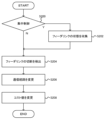
- FIG. 4 is a flowchart showing a first operation example of the wireless communication system 1a according to one embodiment.
- step 100 the wireless communication system 1a determines whether or not the node station 6, for example, performs centralized control of communication path determination.
- the node station 6 proceeds to the processing of S102 if centralized control is to be performed (S100: Yes), and proceeds to the processing of S104 if centralized control is not to be performed (S100: No).
- the node station 6 collects the usage rate of the transmission buffer from each node station 6.
- the node station 6 confirms the usage rate of the transmission buffer of each node station 6. For example, the node station 6 uses the usage rate of the transmission buffer of each node station 6 to confirm whether or not there is a change in the communication status that requires a change in the cost value.
- the node station 6 changes the cost value of each communication link according to the usage rate of the transmission buffer.
- the node station 6 uses the changed cost value to calculate the communication route that minimizes the total cost value of the communication links.
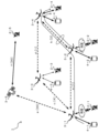
- FIG. 5 is a diagram showing a first operation example of the wireless communication system 1a according to one embodiment.
- the node station 6-1 transmits 1 Gbps data to the node station 6-2 via the communication link a, and transmits the data to the node station 6-3 via the node station 6-2. .
- the node station 6 changes the cost value of the communication link according to the usage rate of the transmission buffer.
- the transmission buffer usage rate is calculated by the following formula (2).
- the cost value at this time is calculated by the following formula (3).
- the number of input links to the node station 6-2 is 1 and the buffer usage rate is 75%.
- the node station 6-2 changes the cost value by setting the link speed of the communication link a to 0.25 Gbps.
- FIG. 6 is a flowchart showing a second operation example of the wireless communication system 1a according to one embodiment.
- the wireless communication system 1a determines whether or not the node station 6, for example, performs centralized control of communication route determination. If the node station 6 performs centralized control (S200: Yes), it proceeds to the processing of S202, and if it does not perform centralized control (S200: No), it proceeds to the processing of S204.
- the node station 6 collects the state of the feeder link from each node station 6.
- the node station 6 detects disconnection of the feeder link.
- the node station 6 calculates the communication route with the smallest total cost value and changes the communication route.
- the node station 6 changes the cost value of the communication route included in the new communication route.
- FIG. 7 is a diagram showing a second operation example of the wireless communication system 1a according to one embodiment.
- the terminal station 7-1 attempts to transmit 1 Gbps data to the base station 5-1 via communication links a and b.
- the wireless communication system 1a establishes a new feeder link via the communication links a, c, and e.
- the cost value of the communication route included in the new communication path is changed.
- the terminal station 7-1 transmits data to another base station (base station 5-2) via the node stations 6-1 and 6-2.
- the node station 6 calculates the cost value using the following formula (4).
- FIG. 8 is a flowchart showing a third operation example of the wireless communication system 1a according to one embodiment. As shown in FIG. 8, at step 300 (S300), the wireless communication system 1a detects a drop in reception C/N of the feeder link.
- the node station 6 changes the feeder link speed according to the reception C/N
- the node station 6 changes the cost value according to the changed feeder link speed.
- the node station 6 uses the changed cost value to calculate the communication route with the minimum total cost value.
- the wireless communication system 1a adaptively controls the link speed according to the reception C/N of the feeder link (when the reception C/N is reduced due to rainfall, etc., the link speed is reduced for communication). ) and calculate the cost value according to the changed link speed.
- FIG. 9 is a flowchart showing a fourth operation example of the wireless communication system 1a according to one embodiment. As shown in FIG. 9, at step 400 (400), the wireless communication system 1a calculates the communication route with the minimum total cost value.
- the node station 6 determines whether or not the minimum total cost value is equal to or greater than a predetermined threshold.
- the node station 6 proceeds to the process of S404 when the minimum value of the total cost value is equal to or greater than the predetermined threshold value (S402: Yes), and when the minimum value of the total cost value is less than the predetermined threshold value (S402: No ), the process proceeds to S408.
- step 404 the node station 6 determines whether or not the data to be routed through the communication path whose minimum total cost value is equal to or greater than a predetermined threshold corresponds to predetermined specific traffic. .
- the node station 6 proceeds to the processing of S406 if the data corresponds to the specific traffic (S404: Yes), and proceeds to the processing of S408 if the data does not correspond to the specific traffic (S404: No).
- the node station 6 determines a predetermined fixed communication path as the communication path for transmitting data corresponding to the specific traffic regardless of the cost value.
- the node station 6 determines the communication path for transmitting data that does not correspond to specific traffic as the communication path with the lowest cost value.
- FIG. 10 is a diagram showing a fourth operation example of the wireless communication system 1a according to one embodiment.
- the wireless communication system 1a sets a threshold value for the total cost value, and assumes that all communication routes are congested when the total cost value is equal to or greater than a predetermined threshold value for any communication route. Then, the wireless communication system 1a communicates the specific traffic using a predetermined fixed communication path regardless of the cost value.
- the communication link between the node station 6-1 and the base station 5-1, the communication link between the node station 6-2 and the base station 5-2, and the communication link between the node station 6-3 and the base station 5-3 communication link is disabled due to rain clouds or the like.
- the wireless communication system 1a transfers the data to either the base station 5-4 or the base station 5-5 with which the terminal station 7-1 can transmit the data.
- communication path X using communication links a and b, communication path Y using communication links c and d, and communication path Z using communication links e and f are available for data transfer.
- the threshold value of the total cost value for the communication path is 15.
- the wireless communication system 1a determines that the total cost value 18 of the communication path Y having the smallest total cost value exceeds the threshold value 15. Therefore, regardless of the total cost value, the predetermined fixed communication route Z is determined as the communication route for the data transmitted by the terminal station 7-1.
- the node station 6 determines whether or not the traffic is specific traffic using QCI (QoS Class Identifier) from the terminal station 7 or the like.
- the wireless communication system 1a may be configured to operate by combining the operations of the first to fourth operation examples described above.
- FIG. 11 is a diagram illustrating a configuration of a modified example (network control device 8a) of the network control device 8 in the wireless communication system 1a according to one embodiment.
- the network control device 8a has a collection unit 80 and a route control unit 65, for example.
- Collection unit 80 collects data transmitted via mobile network 10 and outputs the data to route control unit 65 .
- the data collected by the collection unit 80 is the same as the data acquired by the node station 6 described above.
- the collection unit 80 collects the transmission buffer usage status and feeder link status acquired by each node station 6 .
- the network control device 8a also has the same function as the route control unit 65 provided in the node station 6 (see FIG. 3), and adaptively controls the communication path in the wireless communication system 1a. Therefore, in the radio communication system 1a, each node station 6 need not have the function of adaptively controlling the communication path, as long as the network control device 8a has the function of adaptively controlling the communication path.
- the wireless communication system 1a acquires correspondence information corresponding to the amount of data transmitted by each of the node stations 6 each time the communication situation changes, and based on each of the acquired correspondence information, the plurality of node stations 6 Since the cost value per unit link speed between multiple base stations 5, node stations 6, and terminal stations 7 fluctuates in communication conditions between wireless communication devices, traffic on a specific communication route can be maintained. Wireless communication can be performed efficiently while reducing concentration.
- the functions of the base station 5, the node station 6, the terminal station 7, and the network control devices 8 and 8a are partially or wholly implemented by PLD (Programmable Logic Device), FPGA (Field Programmable Gate Array), or the like. It may be configured by hardware, or may be configured as a program executed by a processor such as a CPU.
- PLD Processable Logic Device
- FPGA Field Programmable Gate Array
- the wireless communication system 1a can be implemented using a computer and a program, and the program can be recorded on a storage medium or provided through a network.
Landscapes
- Engineering & Computer Science (AREA)
- Computer Networks & Wireless Communication (AREA)
- Signal Processing (AREA)
- Physics & Mathematics (AREA)
- Astronomy & Astrophysics (AREA)
- General Physics & Mathematics (AREA)
- Mobile Radio Communication Systems (AREA)
Abstract
一実施形態にかかる無線通信方法は、送信バッファを備えて移動する複数のノード局が切替可能な無線の通信経路を介してデータを伝送する無線通信方法において、ノード局それぞれが伝送するデータ量に対応する対応情報を通信状況が変動するごとにそれぞれ取得する取得工程と、取得した対応情報それぞれに基づいて、複数のノード局間の単位リンク速度当たりのコスト値を変更する変更工程と、変更したコスト値を用いて、複数のノード局間のコスト値を算出する算出工程と、算出したコスト値の合計が最小となる経路を通信経路として決定する決定工程とを含む。
Description
本発明は、無線通信方法及び無線通信システムに関する。
近年では、モバイル通信システムが発展し、地上の大部分においてモバイルサービスを享受することができるようになっている。また、今後に商用化が期待される第5世代(Beyond 5G)又は第6世代のモバイル通信システムにおける要求条件の1つとして、超カバレッジ化がある。
超カバレッジ化とは、山岳、海上、及び空中など、既存の基地局を敷設するコストが高価である場合、又は基地局の敷設が困難な場所などへサービスエリアを拡大することである。また、自然災害などに対する国土強靭化も必要とされており、地上災害に強い通信システムの登場が望まれている。
このような無線通信システムを実現するために、静止衛星・中軌道衛星(MEO:Medium Earth Orbit)・低軌道衛星(LEO:Low Earth Orbit)・高高度疑似衛星(HAPS:High Altitude Platform Station)、無人飛行体(UAV:Unmanned Aerial Vehicle )、及びドローンなどを用いた非地上ネットワーク(NTN:Non Terrestrial Network)が脚光を浴びている(例えば、非特許文献1参照)。
NTNでは、衛星及びHAPSは、互いに通信リンクを接続してネットワークを形成し、さらに地上基地局を介して地上のモバイルネットワークと接続している。衛星及びHAPSは、モバイル基地局機能を搭載している。
そして、端末局が送信したトラフィックのパケットは、ルーティング機能によって地上基地局と接続している衛星及びHAPSにパケット転送され、インターネット網に送られる。インターネット網から他の端末局へ送信されるパケットも、ルーティング機能によって同様な処理が行われる。
多田祐太、外3名、「階層型衛星ネットワークにおける効率的な経路制御に関する一考察」、信学技報、電子情報通信学会、2010年、pp.45-50
NTNなどのように、通信リンクごとに遅延及び速度に大きな差異があるネットワークでは、リンクごとのコスト値を算出して経路を決定する手法が検討されている。例えば、NTNにおいて通信経路を決定する場合、通信リンクごと算出したコスト値の合計が最小となる経路を通信経路として選択する。
しかしながら、衛星及びHAPSなどで使用される高周波数帯の無線通信では、降雨減衰などによって通信状況が変動すると、一部の低コスト値のリンクにトラフィックが集中し、輻輳が生じ得るという問題があった。
本発明は、上述した課題を鑑みてなされたものであり、複数の無線通信装置間の通信状況が変動しても、特定の通信経路にトラフィックが集中することを低減しつつ、効率的に無線通信を行うことができる無線通信方法及び無線通信システムを提供することを目的とする。
本発明の一実施形態にかかる無線通信方法は、送信バッファを備えて移動する複数のノード局が切替可能な無線の通信経路を介してデータを伝送する無線通信方法において、前記ノード局それぞれが伝送するデータ量に対応する対応情報を通信状況が変動するごとにそれぞれ取得する取得工程と、取得した前記対応情報それぞれに基づいて、複数の前記ノード局間の単位リンク速度当たりのコスト値を変更する変更工程と、変更したコスト値を用いて、複数の前記ノード局間のコスト値を算出する算出工程と、算出したコスト値の合計が最小となる経路を通信経路として決定する決定工程とを含むことを特徴とする。
また、本発明の一実施形態にかかる無線通信システムは、送信バッファを備えて移動する複数のノード局が切替可能な無線の通信経路を介してデータを伝送する無線通信システムにおいて、前記ノード局それぞれが伝送するデータ量に対応する対応情報を通信状況が変動するごとにそれぞれ取得する取得部と、前記取得部が取得した前記対応情報それぞれに基づいて、複数の前記ノード局間の単位リンク速度当たりのコスト値を変更する変更部と、前記変更部が変更したコスト値を用いて、複数の前記ノード局間のコスト値を算出する算出部と、前記算出部が算出したコスト値の合計が最小となる経路を通信経路として決定する決定部とを有することを特徴とする。
本発明によれば、複数の無線通信装置間の通信状況が変動しても、特定の通信経路にトラフィックが集中することを低減しつつ、効率的に無線通信を行うことができる。
まず、本発明がなされるに至った背景について、図12を用いて説明する。図12は、無線通信システム1の構成例を示す図である。図12に示すように、無線通信システム1は、例えば基地局(地上基地局)2-1~2-5、及び、ノード局3-1~3-5を備え、複数の端末局(地上端末局)4-1~4-4がそれぞれ接続可能にされている。
ノード局3-1~3-5は、無人飛行体又は衛星などの非地上で移動する無線通信装置であり、それぞれモバイル基地局機能を備えて、例えば通信リンクa~fを接続してNTNを構成している。
無線通信システム1は、通信経路を決定するときに、通信リンクごとに算出したコスト値の合計が最小となる経路を通信経路として選択する。コスト値は、下式(1)によって算出される。例えば、リンク速度、リンク遅延は、ユーザが設定する固定値である。
例えば、速度の基準値を100Mbpsとした場合、10Mbpsの通信リンクのコスト値は”10”、100Mbpsの通信リンクのコスト値は”1”となる。つまり、10Mbpsの通信リンクは、単位リンク速度(例えば1Mbps)当たりのコスト値が100Mbpsの通信リンクの10倍となる。そして、無線通信システム1は、より高速な通信リンクを選択する。
また、遅延の基準値を1sとした場合、遅延が10msの通信リンクのコスト値は”100”、100msの通信リンクのコストは”10”となる。そして、無線通信システム1は、より低遅延の通信リンクを選択する。
このように、無線通信システム1は、上式(1)によりコスト値を算出し、高速かつ低遅延の通信リンクを通信経路として選択しやすくなるように構成されている。
図12に示した例では、例えば通信リンクaのコスト値は”1”、通信リンクbのコスト値は”2”、通信リンクcのコスト値は”4”、通信リンクdのコスト値は”1”、通信リンクeのコスト値は”30”、通信リンクfのコスト値は”30”であるとする。
例えば、無線通信システム1は、基地局2-1とノード局3-1との通信リンク(フィーダリンク)、及び、基地局2-2とノード局3-2との通信リンク(フィーダリンク)がそれぞれ雨雲などによって遮断された場合(通信不可となった場合)、基地局(地上基地局)と通信可能なフィーダリンクを有するノード局にトラフィック(データ)を転送する。
このとき、無線通信システム1は、コスト値の合計が最小となる通信経路を選択する。つまり、端末局4-1は、コスト値の合計が最小の3(=1+2)となる通信リンクa,bを介して基地局2-4に接続される。端末局4-2は、コスト値の合計が最小の2となる通信リンクbを介して基地局2-4に接続される。
したがって、通信リンクbには、端末局4-1からのトラフィックと、端末局4-2からのトラフィックが集中することになり、輻輳が生じ得る。
そこで、以下に説明する一実施形態にかかる無線通信システム1aは、複数の無線通信装置間の通信状況が変動しても、特定の通信経路にトラフィックが集中することを低減しつつ、効率的に無線通信を行うことができるように構成されている。
図1は、一実施形態にかかる無線通信システム1aの構成例を示す図である。図1に示すように一実施形態にかかる無線通信システム1aは、例えば複数の基地局(地上基地局)5、及び複数のノード局6を備え、複数の端末局(地上端末局)7がそれぞれ接続可能にされている。
ノード局6は、静止衛星(GEO)、中軌道衛星(MEO)、低軌道衛星(LEO)、高高度疑似衛星(HAPS)、ドローン、無人飛行体(UAV)、又は航空機などである。
ノード局6それぞれは、通信リンクを互いに接続し、基地局5とも通信リンクを接続し、ノード局の種別ごとにネットワークを形成している。例えばノード局ネットワークAは、静止衛星である複数のノード局6を含み、ノード局ネットワークBは、無人飛行体である複数のノード局6を含む。
また、複数の基地局5それぞれは、モバイルネットワーク10を介してネットワーク制御装置8及びインターネット網12に接続されている。ネットワーク制御装置8は、各ノード局6などからモバイルネットワーク10を介して情報を取得する。ネットワーク制御装置8は、定期的に情報を取得してもよいし、フィーダリンク切断などのイベントが発生したときに、ノード局6から情報を受信してもよい。
なお、ノード局6などのように、複数ある構成のいずれかを特定する場合には、ノード局6-1,ノード局6-2,ノード局6-3・・・のように記載して区別することとする。
ノード局6それぞれは、送信バッファを備えて移動する無人飛行体又は衛星などの非地上で移動する無線通信装置であり、それぞれルーティング機能を含むモバイル基地局機能を備えて、それぞれ通信リンクを接続してNTNを構成している。
そして、無線通信システム1aは、複数のノード局6が切替可能な無線の通信経路を介してデータを伝送するときに、通信リンクごとに算出したコスト値の合計が最小となる経路を通信経路として選択する。
図2は、ノード局6の構成例を示す図である。図2に示すように、ノード局6は、例えば複数のノード局間通信部60、端末局間通信部61、基地局間通信部62、トラフィックモニタ63、フィーダリンク監視部64、及びルート制御部65を有する。
ノード局間通信部60は、近接する他のノード局6との間で通信リンクを接続して無線通信を行う。端末局間通信部61は、所定の通信エリア内の端末局7との間で通信リンクを接続して無線通信を行う。基地局間通信部62は、所定の通信エリア内の基地局5との間で通信リンクを接続して無線通信を行う。
トラフィックモニタ63は、例えば各ノード局間通信部60、端末局間通信部61、及び基地局間通信部62それぞれのトラフィック量などを検出し、検出したトラフィック量それぞれをルート制御部65に対して出力する。また、トラフィックモニタ63は、当該ノード局6の送信バッファの使用状況を測定する。
フィーダリンク監視部64は、基地局間通信部62が行うフィーダリンクを監視し、監視したフィーダリンクの結果をルート制御部65に対して出力する。
ルート制御部65は、例えばトラフィックモニタ63から入力されたトラフィック量及び送信バッファの使用状況それぞれ、及びフィーダリンク監視部64から入力されたフィーダリンクの結果などに基づいて、無線通信システム1aの複数の通信リンクそれぞれのコスト値を算出し、無線通信システム1aにおいて伝送するパケット(データ)の通信経路(ルート)などを決定して制御する。
つまり、ルート制御部65は、コスト値の計算、隣接する他のノード局6とのコスト値の交換、及びトラフィックの通信経路の決定を行う。
図3は、ルート制御部65の構成例を示す図である。図3に示すように、ルート制御部65は、例えば記憶部650、取得部652、算出部654、決定部656、及び変更部658を有する。
記憶部650は、メモリなどであり、例えばルート制御部65が複数の通信リンクそれぞれのコスト値を算出して通信経路を制御するために必要なデータを記憶しており、記憶しているデータを算出部654及び決定部656からのアクセスに応じて出力する。
取得部652は、トラフィックモニタ63が出力したトラフィック量及び送信バッファの使用状況それぞれ、及びフィーダリンク監視部64が出力したフィーダリンクの結果などを取得し、算出部654及び変更部658に対して出力する。
例えば、取得部652は、ノード局6それぞれが伝送するデータ量に対応する対応情報を通信状況が変動するごとにそれぞれ取得し、算出部654及び変更部658に対して出力する。
より具体的には、取得部652は、ノード局6それぞれの送信バッファの使用率を対応情報としてそれぞれ取得する。また、取得部652は、通信経路が切替えられたことにより新たに当該ノード局6に対して入力されるデータ量を当該ノード局6が伝送するデータ量から差し引いた後のデータ量を対応情報としてそれぞれ取得してもよい。また、取得部652は、ノード局6それぞれが受信するデータのC/N(搬送波対雑音比)を対応情報としてそれぞれ取得してもよい。
算出部654は、記憶部650が記憶しているデータ、及び、取得部652が取得した対応情報(トラフィック量など)それぞれを用いてコスト値を算出し、算出したコスト値を用いて、複数のノード局6間のコスト値を算出する。そして、算出部654は、算出した複数のノード局6間のコスト値を記憶部650及び決定部656に対して出力する。
また、算出部654は、後述する変更部658がコスト値を変更した場合には、変更部658が変更したコスト値を用いて、複数のノード局6間のコスト値を算出する。
決定部656は、記憶部650が記憶しているデータ、及び、算出部654が算出したコスト値の合計が最小となる経路を通信経路として決定し、決定した通信経路を示す情報を、ノード局6を構成する各部へ出力する。
また、決定部656は、算出部654が算出した全ての通信経路のコスト値が所定の閾値以上であった場合、予め定められた特定の通信経路を特定のデータに対する通信経路として決定してもよい。
変更部658は、取得部652が取得した対応情報それぞれに基づいて、複数のノード局6間の単位リンク速度当たりのコスト値を変更し、変更したコスト値を算出部654に対して出力する。
つまり、算出部654は、無線通信システム1aにおける通信リンクの通信状況が変動した場合、変更部658が通信状況に応じて変更したコスト値を用いて、複数のノード局6間のコスト値を算出する。そして、決定部656は、通信リンクの通信状況の変動に応じて無線通信システム1aにおける通信経路を決定する適応制御を行う。
次に、無線通信システム1aのより具体的な動作例(第1動作例~第4動作例)について説明する。図4は、一実施形態にかかる無線通信システム1aの第1動作例を示すフローチャートである。
図4に示すように、ステップ100(S100)において、無線通信システム1aは、例えばノード局6が通信経路の決定の集中制御を行うか否かを判定する。ノード局6は、集中制御を行う場合(S100:Yes)にはS102の処理に進み、集中制御を行わない場合(S100:No)にはS104の処理に進む。
ステップ102(S102)において、ノード局6は、各ノード局6から送信バッファの使用率を収集する。
ステップ104(S104)において、ノード局6は、各ノード局6の送信バッファの使用率を確認する。例えば、ノード局6は、コスト値の変更が必要となる通信状況の変動があるか否かを、各ノード局6の送信バッファの使用率を用いて確認する。
ステップ106(S106)において、ノード局6は、送信バッファの使用率に応じて、通信リンクそれぞれのコスト値を変更する。
ステップ108(S108)において、ノード局6は、変更後のコスト値を用いて、通信リンクの合計コスト値が最小となる通信経路を算出する。
図5は、一実施形態にかかる無線通信システム1aの第1動作例を示す図である。図5に示すように、例えばノード局6-1は、通信リンクaにより1Gbpsのデータをノード局6-2へ送信し、ノード局6-2を介してデータをノード局6-3へ伝送する。
ノード局6は、送信バッファの使用率に応じて通信リンクのコスト値を変更する。送信バッファ使用率は、下式(2)によって算出される。
また、このときのコスト値は、下式(3)によって算出される。

ここで、ノード局6-2への入力リンク数は1であり、バッファの使用率が75%になったとする。通信リンクaからノード局6-2へ入力可能なトラフィックは、1Gbps×(1-0.75)=0.25Gbpsとなる。
この場合、ノード局6-2は、通信リンクaのリンク速度を0.25Gbpsとしてコスト値を変更する。
図6は、一実施形態にかかる無線通信システム1aの第2動作例を示すフローチャートである。図6に示すように、ステップ200(S200)において、無線通信システム1aは、例えばノード局6が通信経路の決定の集中制御を行うか否かを判定する。ノード局6は、集中制御を行う場合(S200:Yes)にはS202の処理に進み、集中制御を行わない場合(S200:No)にはS204の処理に進む。
ステップ202(S202)において、ノード局6は、各ノード局6からフィーダリンクの状態を収集する。
ステップ204(S204)において、ノード局6は、フィーダリンクの切断を検出する。
ステップ206(S206)において、ノード局6は、合計コスト値が最小となる通信経路を算出し、通信経路を変更する。
ステップ208(S208)において、ノード局6は、新たな通信経路に含まれる通信ルートのコスト値を変更する。
図7は、一実施形態にかかる無線通信システム1aの第2動作例を示す図である。図7に示すように、例えば端末局7-1は、通信リンクa,bを介して1Gbpsのデータを基地局5-1へ伝送しようとする。このとき、無線通信システム1aは、ノード局6-1と基地局5-1とのフィーダリンク(通信リンクb)が降雨などにより通信不可である場合、通信リンクa,c,eを介する新たな通信経路に切替えを行った後、新たな通信経路に含まれる通信ルートのコスト値を変更する。この場合、端末局7-1は、ノード局6-1及びノード局6-2を介して他の基地局(基地局5-2)へデータを伝送する。
具体的には、ノード局6は、下式(4)によってコスト値を算出する。
無線通信システム1aは、新たな通信経路に含まれる通信リンクcには、最大で通信不可となったフィーダリンクのリンク速度分(1Gbps)のトラフィックが入力されると想定し、通信リンクcのリンク速度(5Gbps)から1Gbpsを減算した4Gbpsをリンク速度として変更後のコスト値を計算する。つまり、通信リンクcのリンク速度は5Gbpsであっても、ノード局6-2は、通信リンクcのリンク速度を5Gbps-1Gbps=4Gbpsとしてコスト値を算出する。
図8は、一実施形態にかかる無線通信システム1aの第3動作例を示すフローチャートである。図8に示すように、ステップ300(S300)において、無線通信システム1aは、フィーダリンクの受信C/N低下を検出する。
ステップ302(S302)において、ノード局6は、受信C/Nに応じてフィーダリンク速度を変更する
ステップ304(S304)において、ノード局6は、変更後のフィーダリンク速度に応じてコスト値を変更する。
ステップ306(S306)において、ノード局6は、変更後のコスト値を用いて、合計コスト値が最小となる通信経路を算出する。
つまり、無線通信システム1aは、第3動作例において、フィーダリンクの受信C/Nに応じてリンク速度を適応制御(降雨などにより受信C/Nが低下したときは、リンク速度を低下させて通信を継続させる)し、変更後のリンク速度に応じてコスト値を計算する。
図9は、一実施形態にかかる無線通信システム1aの第4動作例を示すフローチャートである。図9に示すように、ステップ400(400)において、無線通信システム1aは、合計コスト値が最小となる通信経路を算出する。
ステップ402(S402)において、ノード局6は、合計コスト値の最小値が所定の閾値以上であるか否かを判定する。ノード局6は、合計コスト値の最小値が所定の閾値以上である場合(S402:Yes)にはS404の処理に進み、合計コスト値の最小値が所定の閾値未満である場合(S402:No)にはS408の処理に進む。
ステップ404(S404)において、ノード局6は、合計コスト値の最小値が所定の閾値以上である通信経路による伝送するルーティング対象のデータが予め定められた特定トラフィックに該当するか否かを判定する。ノード局6は、データが特定トラフィックに該当する場合(S404:Yes)にはS406の処理に進み、データが特定トラフィックに該当しない場合(S404:No)にはS408の処理に進む。
ステップ406(S406)において、ノード局6は、特定トラフィックに該当するデータを伝送する通信経路を、コスト値によらず、予め定められた固定通信経路に決定する。
ステップ208(S208)において、ノード局6は、特定トラフィックに該当しないデータを伝送する通信経路を、コスト値が最小である通信経路に決定する。
図10は、一実施形態にかかる無線通信システム1aの第4動作例を示す図である。無線通信システム1aは、合計コスト値に閾値を設定し、いずれの通信経路も合計コスト値が所定の閾値以上である場合、いずれの通信経路も混雑していると想定する。そして、無線通信システム1aは、コスト値によらず、予め定められた固定通信経路を用いて特定トラフィックを通信させる。
図10に示した例において、ノード局6-1と基地局5-1の通信リンク、ノード局6-2と基地局5-2の通信リンク、及びノード局6-3と基地局5-3の通信リンクがそれぞれ雨雲などによって通信不可であるとする。
このとき、無線通信システム1aは、端末局7-1が送信するデータを伝送するために、通信可能な基地局5-4又は基地局5-5のいずれかに向けてデータを転送する。例えば、通信リンクa,bを用いる通信経路X、通信リンクc,dを用いる通信経路Y、及び通信リンクe,fを用いる通信経路Zがデータの転送に使用可能である。
例えば、通信経路X、Y,Zそれぞれの合計コスト値を以下の通りとする。
通信経路X:20
通信経路Y:18
通信経路Z:40
通信経路X:20
通信経路Y:18
通信経路Z:40
また、通信経路に対する合計コスト値の閾値が15であるとする。ここで、端末局7-1が送信するデータが予め定められた特定トラフィックに該当する場合、無線通信システム1aは、合計コスト値が最小である通信経路Yの合計コスト値18が閾値15を超過しているため、合計コスト値によらず、予め定められた固定通信経路Zを、端末局7-1が送信するデータの通信経路として決定する。
なお、ノード局6は、特定トラフィックであるか否かを、端末局7からのQCI(QoS Class Identifier)などを用いて決定する。また、無線通信システム1aは、上述した第1動作例~第4動作例までの動作を組み合わせて動作するように構成されてもよい。
次に、無線通信システム1aの変形例について説明する。図11は、一実施形態にかかる無線通信システム1aにおけるネットワーク制御装置8の変形例(ネットワーク制御装置8a)の構成を例示する図である。
ネットワーク制御装置8aは、例えば収集部80及びルート制御部65を有する。収集部80は、モバイルネットワーク10を介して伝送されるデータを収集し、ルート制御部65に対して出力する。収集部80が収集するデータは、上述したノード局6が取得するデータと同様である。
例えば、収集部80は、各ノード局6が取得した送信バッファの使用状況や、フィーダリンク状態を収集する。
また、ネットワーク制御装置8aは、ノード局6が備えるルート制御部65と同様の機能(図3参照)を有し、無線通信システム1aにおける通信経路を適応制御する。したがって、無線通信システム1aは、ネットワーク制御装置8aが通信経路を適応制御する機能を備えていれば、ノード局6それぞれが通信経路を適応制御する機能を備えていなくてもよい。
このように、無線通信システム1aは、ノード局6それぞれが伝送するデータ量に対応する対応情報を通信状況が変動するごとにそれぞれ取得し、取得した対応情報それぞれに基づいて、複数のノード局6間の単位リンク速度当たりのコスト値を変更するので、複数の基地局5、ノード局6、及び端末局7などの無線通信装置間の通信状況が変動しても、特定の通信経路にトラフィックが集中することを低減しつつ、効率的に無線通信を行うことができる。
なお、基地局5、ノード局6、端末局7、及びネットワーク制御装置8,8aがそれぞれ有する各機能は、それぞれ一部又は全部がPLD(Programmable Logic Device)やFPGA(Field Programmable Gate Array)等のハードウェアによって構成されてもよいし、CPU等のプロセッサが実行するプログラムとして構成されてもよい。
例えば、本発明にかかる無線通信システム1aは、コンピュータとプログラムを用いて実現することができ、プログラムを記憶媒体に記録することも、ネットワークを通して提供することも可能である。
1,1a・・・無線通信システム、2,5・・・基地局、3,6・・・ノード局、4,7・・・端末局、8,8a・・・ネットワーク制御装置、10・・・モバイルネットワーク、12・・・インターネット網、60・・・ノード局間通信部、61・・・端末局間通信部、62・・・基地局間通信部、63・・・トラフィックモニタ、64・・・フィーダリンク監視部、65・・・ルート制御部、80・・・収集部、650・・・記憶部、652・・・取得部、654・・・算出部、656・・・決定部、658・・・変更部
Claims (8)
- 送信バッファを備えて移動する複数のノード局が切替可能な無線の通信経路を介してデータを伝送する無線通信方法において、
前記ノード局それぞれが伝送するデータ量に対応する対応情報を通信状況が変動するごとにそれぞれ取得する取得工程と、
取得した前記対応情報それぞれに基づいて、複数の前記ノード局間の単位リンク速度当たりのコスト値を変更する変更工程と、
変更したコスト値を用いて、複数の前記ノード局間のコスト値を算出する算出工程と、
算出したコスト値の合計が最小となる経路を通信経路として決定する決定工程と
を含むことを特徴とする無線通信方法。 - 前記取得工程では、
前記ノード局それぞれの送信バッファの使用率を前記対応情報としてそれぞれ取得すること
を特徴とする請求項1に記載の無線通信方法。 - 前記取得工程では、
通信経路が切替えられたことにより新たに前記ノード局に対して入力されるデータ量を前記ノード局が伝送するデータ量から差し引いた後のデータ量を前記対応情報としてそれぞれ取得すること
を特徴とする請求項1又は2に記載の無線通信方法。 - 前記取得工程では、
前記ノード局それぞれが受信するデータのC/Nを前記対応情報としてそれぞれ取得すること
を特徴とする請求項1~3のいずれか1項に記載の無線通信方法。 - 前記決定工程では、
前記算出工程により算出した全ての通信経路のコスト値が所定の閾値以上であった場合、予め定められた特定の通信経路を特定のデータに対する通信経路として決定すること
を特徴とする請求項1~4のいずれか1項に記載の無線通信方法。 - 送信バッファを備えて移動する複数のノード局が切替可能な無線の通信経路を介してデータを伝送する無線通信システムにおいて、
前記ノード局それぞれが伝送するデータ量に対応する対応情報を通信状況が変動するごとにそれぞれ取得する取得部と、
前記取得部が取得した前記対応情報それぞれに基づいて、複数の前記ノード局間の単位リンク速度当たりのコスト値を変更する変更部と、
前記変更部が変更したコスト値を用いて、複数の前記ノード局間のコスト値を算出する算出部と、
前記算出部が算出したコスト値の合計が最小となる経路を通信経路として決定する決定部と
を有することを特徴とする無線通信システム。 - 前記取得部は、
前記ノード局それぞれの送信バッファの使用率、前記ノード局それぞれが受信するデータのC/N、及び、通信経路が切替えられたことにより新たに前記ノード局に対して入力されるデータ量を前記ノード局が伝送するデータ量から差し引いた後のデータ量の少なくともいずれかを、前記対応情報としてそれぞれ取得すること
を特徴とする請求項6に記載の無線通信システム。 - 前記決定部は、
前記算出部が算出した全ての通信経路のコスト値が所定の閾値以上であった場合、予め定められた特定の通信経路を特定のデータに対する通信経路として決定すること
を特徴とする請求項6又は7に記載の無線通信システム。
Priority Applications (1)
| Application Number | Priority Date | Filing Date | Title |
|---|---|---|---|
| PCT/JP2022/003881 WO2023148829A1 (ja) | 2022-02-01 | 2022-02-01 | 無線通信方法及び無線通信システム |
Applications Claiming Priority (1)
| Application Number | Priority Date | Filing Date | Title |
|---|---|---|---|
| PCT/JP2022/003881 WO2023148829A1 (ja) | 2022-02-01 | 2022-02-01 | 無線通信方法及び無線通信システム |
Publications (1)
| Publication Number | Publication Date |
|---|---|
| WO2023148829A1 true WO2023148829A1 (ja) | 2023-08-10 |
Family
ID=87553343
Family Applications (1)
| Application Number | Title | Priority Date | Filing Date |
|---|---|---|---|
| PCT/JP2022/003881 WO2023148829A1 (ja) | 2022-02-01 | 2022-02-01 | 無線通信方法及び無線通信システム |
Country Status (1)
| Country | Link |
|---|---|
| WO (1) | WO2023148829A1 (ja) |
Citations (2)
| Publication number | Priority date | Publication date | Assignee | Title |
|---|---|---|---|---|
| JP2002064550A (ja) * | 2000-08-17 | 2002-02-28 | Nippon Telegr & Teleph Corp <Ntt> | 衛星/地上経路選択装置 |
| JP2010178145A (ja) * | 2009-01-30 | 2010-08-12 | Oki Electric Ind Co Ltd | パケット中継システム及び無線ノード |
-
2022
- 2022-02-01 WO PCT/JP2022/003881 patent/WO2023148829A1/ja unknown
Patent Citations (2)
| Publication number | Priority date | Publication date | Assignee | Title |
|---|---|---|---|---|
| JP2002064550A (ja) * | 2000-08-17 | 2002-02-28 | Nippon Telegr & Teleph Corp <Ntt> | 衛星/地上経路選択装置 |
| JP2010178145A (ja) * | 2009-01-30 | 2010-08-12 | Oki Electric Ind Co Ltd | パケット中継システム及び無線ノード |
Non-Patent Citations (1)
| Title |
|---|
| KAZUMA YOSHIDA, HIROKI NISHIYAMA, NEI KATO, NAOKO YOSHIMURA, MORIO TOYOSHIMA, NAOTO KADOWAKI: "A Study on a Route Control Method to Avoid Congestion in the Destination Area for Two-Layered Satellite Networks", IEICE TECHNICAL REPORT, SAT, IEICE, JP, vol. 112, no. 51 (SAT2012-5), 17 May 2012 (2012-05-17), JP, pages 23 - 28, XP009548312 * |
Similar Documents
| Publication | Publication Date | Title |
|---|---|---|
| US10027508B2 (en) | Extended ring-like communication architecture | |
| US8385921B1 (en) | Backhaul aware radio access networks | |
| US9425985B1 (en) | Protection switching in radio networks | |
| CN111294108B (zh) | 一种面向正交圆轨道构型卫星星座的高效路由方法 | |
| US8406126B1 (en) | Ring-like communication architecture | |
| CN104683016A (zh) | 基于最小化时延的多层卫星网络最优业务分布路由方法 | |
| CN111416655A (zh) | 一种基于虚拟拓扑的低轨卫星路由改进方法 | |
| Bacco et al. | Networking challenges for non-terrestrial networks exploitation in 5G | |
| CN112019255B (zh) | 一种透明和处理混合的低轨卫星间组网通信系统和方法 | |
| CN109714270B (zh) | 基于事件触发的卫星路由负载均衡方法 | |
| CN112311441B (zh) | 低轨星座网络中的拥塞避免路由方法 | |
| US8369364B2 (en) | Path multiplexing communication system, communication node, and communication method | |
| CN109586785B (zh) | 基于k最短路径算法的低轨卫星网络路由策略 | |
| CN110391983A (zh) | 面向星地一体化网络的分布式拥塞避免路由算法 | |
| WO2008079471A1 (en) | Method and apparatus for maintaining traffic flow in a mesh network | |
| CN109672625A (zh) | 一种优化时延的低轨卫星馈电负载均衡方法及系统 | |
| CN113489525A (zh) | 一种用于leo卫星星座的路由方法 | |
| Zhang et al. | Joint data downloading and resource management for small satellite cluster networks | |
| US20060039301A1 (en) | Node apparatus and RPR network | |
| CN114125987B (zh) | 空天地一体化网络的路由方法和装置 | |
| Ning et al. | Load-balancing routing algorithm against inter-satellite link congestion in LEO satellite optical networks | |
| Yang et al. | Routing protocol design for drone-cell communication networks | |
| WO2023148829A1 (ja) | 無線通信方法及び無線通信システム | |
| CN110224937B (zh) | 一种卫星网络路由方法、设备及装置 | |
| CN115882931A (zh) | 一种多层卫星数据转发方法及系统 |
Legal Events
| Date | Code | Title | Description |
|---|---|---|---|
| 121 | Ep: the epo has been informed by wipo that ep was designated in this application |
Ref document number: 22924742 Country of ref document: EP Kind code of ref document: A1 |
|
| ENP | Entry into the national phase |
Ref document number: 2023578232 Country of ref document: JP Kind code of ref document: A |