WO2023140388A1 - Alloy, alloy member and product - Google Patents
Alloy, alloy member and product Download PDFInfo
- Publication number
- WO2023140388A1 WO2023140388A1 PCT/JP2023/002126 JP2023002126W WO2023140388A1 WO 2023140388 A1 WO2023140388 A1 WO 2023140388A1 JP 2023002126 W JP2023002126 W JP 2023002126W WO 2023140388 A1 WO2023140388 A1 WO 2023140388A1
- Authority
- WO
- WIPO (PCT)
- Prior art keywords
- alloy
- magnesium
- element group
- lattice mismatch
- less
- Prior art date
Links
Images


Classifications
-
- C—CHEMISTRY; METALLURGY
- C22—METALLURGY; FERROUS OR NON-FERROUS ALLOYS; TREATMENT OF ALLOYS OR NON-FERROUS METALS
- C22C—ALLOYS
- C22C30/00—Alloys containing less than 50% by weight of each constituent
Definitions
- the present invention relates to alloys, alloy members, and products using the same that are resistant to alloys in a molten or plastic state, particularly magnesium alloys.
- JIS SKD61 for example, is used for molds used for magnesium alloy die casting and the like. Repeated casting with the same mold causes damage to the mold. The main cause of damage is erosion. Erosion is said to occur because the portion of the mold that contacts the molten magnesium alloy is alloyed and the melting point is lowered. When the erosion becomes severe, the eroded portion is repaired by overlaying with welding. As the repair material, an alloy having a high melting point and excellent resistance to creep at high temperatures is preferred. An example of this alloy is disclosed in US Pat.
- Patent Document 2 discloses a multi-component HEA containing at least one member of the group consisting of molybdenum, hafnium, tungsten, vanadium and chromium in addition to titanium, zirconium, niobium and tantalum. Patent Document 2 discloses that HEA is used as a biomedical metallic material.
- an object of the present invention is to provide a multicomponent alloy, an alloy member, and a product using the same having resistance to magnesium, particularly corrosion resistance and mechanical strength, during processing such as casting of a magnesium alloy.
- Non-Patent Documents 1 to 6 disclose technical documents necessary for supplementary explanation of the embodiments of the present invention.
- Non-Patent Document 1 describes a method of simulating the process of atomic motion based on the fundamental equations of quantum mechanics, that is, the calculation principle of the first-principles molecular dynamics method. The electrons and nuclei that make up the atoms in a material obey the laws of quantum mechanics, so this simulation can be used to assess the properties of the material.
- Non-Patent Document 2 mentions a method of calculating the diffusion coefficient by molecular dynamics simulation.
- Non-Patent Document 3 refers to a method of calculating adsorption energy by molecular dynamics simulation.
- Other Non-Patent Documents 4 to 6 will be referred to in the section of the mode for carrying out the invention which will be described later.
- a first invention for achieving the above-mentioned object is an alloy characterized by containing Fe, Cr and V as the first element group in an amount of 10 at % or more and 45 at % or less, respectively, having a lattice mismatch with respect to Mg of 13% or more, and dislocation transfer barrier energy of 300 kJ/mol or more.
- one or two or more selected from Mn, Co, Ni, Si, Ge, Ru and Pd may be included at 10 at % or more and 25 at % or less, respectively.
- the adsorption energy for Mg is 0.2 J/m 2 or less.
- the magnesium erosion resistance is excellent, and since the dislocation movement barrier energy is a predetermined value or more, an alloy having sufficient rigidity can be obtained.
- Such an effect can be obtained more reliably if the adsorption energy for magnesium is 0.2 J/m 2 or less.
- the second invention is an alloy member characterized by comprising, in at least a part thereof, an alloy containing Fe, Cr and V as the first element group in an amount of 10 at % or more and 45 at % or less, the balance being composed of unavoidable elements, a lattice mismatch with respect to Mg of 13% or more, and a dislocation transfer barrier energy of 300 kJ/mol or more.
- the alloy may further contain, as the second element group, one or more selected from Mn, Co, Ni, Si, Ge, Ru and Pd at 10 at % or more and 25 at % or less.
- the adsorption energy of the alloy to Mg is 0.2 J/m 2 or less.
- the magnesium erosion resistance is excellent, and since the dislocation movement barrier energy is a predetermined value or more, an alloy member having sufficient rigidity can be obtained.
- the adsorption energy to magnesium is 0.2 J/m 2 or less, the above effect can be obtained more reliably.
- a third invention is a product at least partly comprising the alloy member according to the second invention.
- the product is a mold for working with magnesium.
- the third invention it is possible to obtain a product that is excellent in magnesium erosion resistance and has sufficient rigidity.
- a mold for working magnesium that can suppress erosion loss in casting of magnesium or the like.
- the difficulty in adsorbing magnesium is expressed, for example, by the low adsorption energy (also called detachment energy) disclosed in Non-Patent Document 5, and it can be said that the smaller the adsorption energy, the more difficult it is to adsorb.
- the adsorption energy is obtained by calculation, and the calculation method will be described later.
- the adsorption energy is governed by the lattice constant and the lattice mismatch, which is the relative difference between them.
- the lattice constant and the lattice mismatch which is the relative difference between them, are more dominant factors than other factors (surface energy, cohesive energy, electronegativity). Therefore, in the present invention, attention is focused on the lattice mismatch, which is the relative difference in lattice constant.
- the inventors have found that magnesium resistance, particularly excellent erosion resistance, can be obtained by using a material having a large lattice mismatch with respect to magnesium.
- the lattice mismatch is also called lattice mismatch, and is obtained by calculation, the calculation method of which will be described later.
- Non-Patent Document 5 describes the bonding strength such as the interface strength between the wiring film and the barrier film of electronic components, and has aimed to reduce the lattice mismatch, ideally to zero. Contrary to these, the present invention obtains resistance to magnesium by increasing lattice mismatch, that is, the property of being difficult to react with molten magnesium, which is the opposite of the conventional idea.
- alloys are preferable because they are less likely to deform and less likely to break.
- the cycle time is shortened in order to increase productivity, the mold frequently repeats high and low temperatures, so thermal stress tends to concentrate. Therefore, it is preferable that the material has high mechanical strength.
- the deformation of metals such as alloys is represented by the movement of dislocations
- the difficulty of deformation that is, the mechanical strength of metals, is represented by the difficulty of movement of dislocations.
- Non-Patent Document 4 the mechanical strength of a metal is represented by the dislocation movement barrier energy, and it is determined that the higher the dislocation movement barrier energy required to move dislocations, the harder the metal to deform and the higher the mechanical strength. Therefore, in the present invention, attention is paid also to the movement barrier energy of dislocations. The details of the method of calculating the dislocation mobility barrier energy and the like will be described later.
- FIG. 1 is a diagram showing the relationship between lattice mismatch with magnesium (hereinafter sometimes simply referred to as lattice mismatch) and magnesium adsorption energy (hereinafter sometimes simply referred to as adsorption energy) for several metal elements. From FIG. 1, it can be seen that the adsorption energy decreases as the lattice mismatch increases. In particular, if the lattice mismatch is 13% or more, the adsorption energy will be sufficiently low that it will not drop any further. Therefore, the lattice mismatch is desirably 13% or more.
- the alloy according to this embodiment contains Fe, Cr and V as the first element group. Further, one or more selected from Mn, Co, Ni, Si, Ge, Ru and Pd may be included as the second element group.
- the second element group is included, the amount of each contained element of the second element group is 10 at % to 25 at %.
- B may be added so as to be 1 to 60 at %, preferably 10 to 45 at %, more preferably 14 to 40 at %. Moreover, it is preferably contained in an amount of 1.5 times or more, and more preferably contained in an amount of 2 times or more with respect to the amount of each element of the first element group or the first element group and the second element group.
- the range of element ratios of the first element group and the second element group is recognized as the content of the elements that make up the high entropy alloy.
- the alloy according to the present embodiment may contain unavoidable impurities as the balance in addition to the first element group and the second element group.
- unavoidable impurity elements such as C, N, and O may be contained at 500 ppm or less.
- the high entropy alloy referred to in this specification refers to an alloy containing 45 at % or less of each element at maximum, and more preferably 34 at % or less of each element at maximum.
- the alloy according to the present embodiment preferably has a small adsorption energy and a small diffusion coefficient in order to prevent magnesium from approaching and reacting with the surface or entering and reacting. For this reason, the lattice mismatch with Mg must be 13% or more.
- the deformation of a metal is represented by the movement of dislocations, and the resistance to deformation, that is, the mechanical strength of a metal is represented by the resistance to movement of dislocations.
- the mechanical strength of a metal is represented by the migration barrier energy of dislocations. If this is large, for example, the hardness described later increases.
- the alloy according to the present embodiment preferably has a dislocation mobility barrier energy (for example, a dislocation mobility barrier energy at 800° C.) of 300 kJ/mol or more.
- the dislocation migration barrier energy is one index representing the mechanical strength of the alloy according to this embodiment.
- the alloy according to this embodiment preferably has an adsorption energy (for example, adsorption energy at 800° C.) of 0.2 J/m 2 or less. It can be said that the adsorption energy is one indicator of magnesium resistance. Therefore, in the present embodiment, the adsorption energy is preferably 0.2 J/m 2 or less.
- the adsorption energy in this embodiment is more preferably 0.15 J/m 2 or less, more preferably 0.1 J/m 2 or less, still more preferably 0.08 J/m 2 or less.
- diffusion coefficient of magnesium It is important to improve resistance that dissolved magnesium does not enter and react from the surface. The ease with which magnesium penetrates can be evaluated by the diffusion coefficient that penetrates from the surface to the inside. It can be said that the diffusion coefficient is one indicator of magnesium tolerance. Details of the diffusion coefficient will be described later.
- the alloy according to the present embodiment preferably has a Vickers hardness (HV) of 430 or higher at room temperature. Hardness is one indicator of the mechanical strength of the alloy according to this embodiment.
- alloys according to this embodiment have a body-centered cubic (bcc) crystal structure.
- the crystal structure is observed by X-ray diffraction (XRD).
- XRD X-ray diffraction
- alloys having a single type of bcc structure alloys having a plurality of types of bcc structures may also be used.
- the alloy according to the present embodiment most preferably has a body-centered cubic lattice structure in its entirety, preferably at a volume ratio (content ratio) of 60% or more, more preferably at a volume ratio (content ratio) of 80% or more.
- Each item can be calculated using a molecular dynamics simulation as disclosed in Non-Patent Document 1 and the like.
- the lattice constant for calculating the lattice mismatch was defined as follows based on Non-Patent Document 5. That is, the mismatch between the short-side lattice constant a and the long-side lattice constant b of the face-centered rectangular lattice representing the plane with the highest atomic number density, that is, the close-packed crystal plane described below, is expressed in percent, and is defined as the short-side lattice mismatch ⁇ a and the long-side lattice mismatch ⁇ b. Since ⁇ a with a short interatomic distance is more important, ⁇ a is defined as lattice mismatch in this embodiment unless otherwise specified.
- the short side lattice mismatch ⁇ a with magnesium is as small as about 2% or less
- the long side lattice mismatch ⁇ b is as large as 16% or more, so the arithmetic mean of ⁇ a and ⁇ b was taken as the lattice mismatch.
- the close-packed crystal plane is the (110) plane
- the ratio of short side a to long side b is about 1: ⁇ 2.
- magnesium which is the counterpart material, has a hexagonal close-packed (hcp) crystal structure that is stable at room temperature and pressure, and when the temperature is raised, the body-centered cubic lattice becomes stable.
- the close-packed crystal plane of the hexagonal close-packed structure is the (0001) plane, and the ratio of short side a to long side b is about 1: ⁇ 3. It is known from Non-Patent Document 5 and others that crystal planes other than the close-packed crystal planes defined here have a weak contribution to the adsorption energy and therefore do not have much effect.
- the dislocation migration barrier energy is the barrier energy that the dislocation must overcome on the way from the state before migration to the state after migration, and is calculated by molecular dynamics simulation, for example, in the same manner as the method shown in Non-Patent Document 4.
- the barrier energy was calculated using self-developed molecular dynamics software, and in parallel with Dmol3 and Forcite in Materials Studio of Dassault Systèmes, and it was confirmed that the results of both were consistent.
- the adsorption energy represents the energy required to change the adsorption state to the detachment state, and is obtained by subtracting the energy in the adsorption state from the energy in the detachment state, as shown in Equation (3) in Non-Patent Document 3.
- Adsorption energies were calculated using self-developed molecular dynamics software, and in parallel with Dmol3 and Forcite of Materials Studio of Dassault Systèmes, and it was confirmed that the results of the two agree. The larger this value, the easier it is to adsorb.
- Equation 1 equation (A) and equation (B)), which is the following Einstein relational expression, as shown in Equation (2) of Non-Patent Document 2.
- Equation (B) is obtained by dividing the mean square displacement from t 0 to t + t 0 at the reference time set after sufficient relaxation by 6t, and actually converges in a finite time step, so the diffusion coefficient can be calculated without calculating to infinity.
- r i (t+t 0 ) ⁇ r i (t 0 ) can be calculated from the equation of motion.
- the diffusion coefficient of penetration in the direction perpendicular to the interface it can be calculated from the mean square displacement of the displacement in that direction. The larger the diffusion coefficient, the easier the penetration. In other words, it means that molten magnesium is likely to enter and react from the surface, in other words, it is likely to be eroded.
- each alloy according to this embodiment will be described.
- Table 2 shows the calculation results of lattice mismatch with Mg, dislocation migration barrier energy, and Mg adsorption energy for nine types of alloys according to this embodiment.
- each alloy was made into the alloy of the equielemental ratio. For example, when composed of three elements, each contains 33.3 at % of the constituent elements, when composed of five elements, each contains 20 at % of the constituent elements, and when composed of six elements, each contains 16.6 at %.
- KUMADAI magnesium alloy Mg-Al-Ca
- KUMADAI magnesium alloy is a registered trademark
- all the alloys according to the examples had a lattice mismatch with respect to Mg of 13% or more, a dislocation migration barrier energy of 300 kJ/mol or more, and a Mg adsorption energy of 0.2 J/m 2 or less (0.08 J/m 2 or less).
- the conventional SKD61 alloy had a small lattice mismatch with Mg of less than 13%, and the Mg adsorption energy exceeded 0.2 J/m 2 regardless of the presence or absence of nitriding treatment.
- the PdRuZn alloy which does not contain the first element group and is mainly composed of the second element group, has a lattice mismatch with Mg of 13% or more and satisfies the Mg adsorption energy of 0.2 J/m 2 or less (0.08 J/m 2 or less), but the dislocation migration barrier energy is less than 300 kJ/mol, and sufficient strength cannot be obtained.
- Table 4 shows the manufactured molded article.
- the composition of the shaped article shown in Table 4 is No. 1 and no. 2 contains 33.3 at % each of Fe, Cr and V, which are the first element group.
- No. 3 to No. 7, No. 14 and no. 15 contains 20 at % each of Fe, Cr and V of the first element group and 20 at % each of two selected from the second element group of Mn, Co, Ni and Si.
- No. 10 to No. 13 contains 14.3 at% each of Fe, Cr and V of the first element group, 14.3 at% each of two selected from the second element group of Mn, Co, Ni and Si, and 28.6 at% of B.
- No. 3 is shown in FIG.
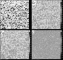
- the structure photograph and elemental mapping of No. 2 are shown in FIG. Thirteen micrographs and elemental mapping are shown.
- FIG. 3 in the shaped body of FeCrV composition, although some segregation was observed, all the elements were melted and alloyed.
- FIG. 4 in the FeCrVB 2 CoNi composition shaped body, the VB 2 added as a powder was not dissolved and scattered in the form of particles. There was also an overlap in the mapping of VB2 and Cr.
- No. An erosion test piece was prepared from the molded body composed of the alloy compositions of 2 and 8, and an erosion test against Mg was performed.
- the erosion test piece had a cylindrical shape with an outer diameter of ⁇ 13, an inner diameter of ⁇ 5.5 and a height of 3.5.
- a similar erosion test was performed on a erosion test piece (No. 0) in which the surface of SKD61, a hot work tool steel generally used for Mg die casting molds, was nitrided.
- SKD61 has a Rockwell hardness of 45 HRC, and the surface is nitrided to a thickness of 50 ⁇ m.
- the prepared erosion test piece was placed so as to be immersed in a 99% pure Mg alloy melted in a melting furnace. While stirring the Mg alloy using a stirring rod rotating at 116 rpm, the erosion test piece was immersed for 1 hour. The temperature of the molten metal was 936K-961K.
- Table 5 shows the results of the Mg corrosion test. As shown in Table 5, the erosion rate of No. 0.0393% in No. 2; 8, 0.1287%, and No. 8 in which the surface of SKD61 as a comparative example was subjected to nitriding treatment. 0 was 0.2778%. Based on the results of the erosion test, No. 0 compared to No. 2 containing Fe, Cr and V as the first element group in an amount of 10 at % or more and 45 at % or less, respectively; An alloy containing 10 at% or more and 45 at% or less of Fe, Cr, and V as the first element group as in No. 8 and further containing 0.5 at% or more and 60 at% or less of B has excellent Mg corrosion resistance.
- the alloy according to the present embodiment can be applied to an alloy member at least partially containing the alloy (for example, the surface of the base material) and to a product at least partially including the alloy member.
- it is preferably applied to molds used for processing magnesium.
- molding can be performed by irradiating an alloy powder having a desired element ratio with an electron beam or a laser beam to melt and solidify it.
- a magnesium die casting mold or the like by forming the alloy of this embodiment at least on the surface of the mold, it is possible to obtain a magnesium die casting mold capable of suppressing erosion caused by magnesium.
Abstract
An alloy according to the present embodiment contains Fe, Cr and V as a first element group. Said alloy may also contain one or more types of element selected from Mn, Co, Ni, Si, Ge, Ru and Pd as a second element group. When the total is 100at% (hereinafter, written the same), the first element group each constitutes 10-45 at%, inclusive (at%=element ratio. Hereinafter, written as 10-45 at%). The Mg lattice mismatch is 13% or higher, and the dislocation movement barrier energy is 300 kJ/mol or higher.
Description
本発明は、溶融状態もしくは可塑性状態にある合金、特にマグネシウム合金に対する耐性を有する合金、合金部材およびこれを用いた製造物に関する。
The present invention relates to alloys, alloy members, and products using the same that are resistant to alloys in a molten or plastic state, particularly magnesium alloys.
マグネシウム合金のダイカスト等に用いられる金型には、例えば、JIS SKD61が用いられている。同じ金型で鋳造を繰り返していると、金型に損傷が生じる。損傷原因の主なものに溶損がある。溶損は、金型のマグネシウム合金の溶湯と接触する部分が合金化して融点が低下するために生ずるとされている。
溶損が激しくなると、溶損した部分に溶接による肉盛りをして補修することが行われる。補修材としては、高融点でかつ高温における耐クリープ特性の優れた耐溶損性を備えた合金が好ましい。この合金の一例が、特許文献1に開示されている。 JIS SKD61, for example, is used for molds used for magnesium alloy die casting and the like. Repeated casting with the same mold causes damage to the mold. The main cause of damage is erosion. Erosion is said to occur because the portion of the mold that contacts the molten magnesium alloy is alloyed and the melting point is lowered.
When the erosion becomes severe, the eroded portion is repaired by overlaying with welding. As the repair material, an alloy having a high melting point and excellent resistance to creep at high temperatures is preferred. An example of this alloy is disclosed in US Pat.
高強度、高耐食性が求められる中で、ハイエントロピー合金(High Entropy Alloy:HEA)が注目を集めている。例えば、特許文献2は、チタン、ジルコニウム、ニオブおよびタンタルに加えて、モリブデン、ハフニウム、タングステン、バナジウムおよびクロムからなる群の少なくとも一種を含む多成分系からなるHEAを開示する。特許文献2のHEAは、生体用金属材料として使用されることが開示されている。
High Entropy Alloy (HEA) is attracting attention as high strength and high corrosion resistance are required. For example, Patent Document 2 discloses a multi-component HEA containing at least one member of the group consisting of molybdenum, hafnium, tungsten, vanadium and chromium in addition to titanium, zirconium, niobium and tantalum. Patent Document 2 discloses that HEA is used as a biomedical metallic material.
しかし、特許文献2が開示する合金では、マグネシウム合金などの溶湯に対する耐溶損性と機械強度が十分でなかった。そこで本発明は、マグネシウム合金の鋳造等の加工時において、マグネシウムに対する耐性、特に耐溶損性と機械強度を備える多元系の合金、合金部材およびこれを用いた製造物を提供することを目的とする。
However, the alloy disclosed in Patent Document 2 did not have sufficient erosion resistance and mechanical strength against molten metal such as magnesium alloy. Accordingly, an object of the present invention is to provide a multicomponent alloy, an alloy member, and a product using the same having resistance to magnesium, particularly corrosion resistance and mechanical strength, during processing such as casting of a magnesium alloy.
なお、非特許文献1~6は、本発明の実施形態を補足説明する上で必要となる技術文献を開示するものである。例えば非特許文献1は、量子力学の基本方程式に基づいて原子が運動する過程をシミュレーションする方法、すなわち第一原理的分子動力学法の計算原理について述べられている。材料中の原子を構成する電子と原子核は量子力学の法則に従うため、このシミュレーションによって材料の特性を評価することができる。非特許文献2は、分子動力学法シミュレーションによって拡散係数を計算する方法について言及している。また、非特許文献3は、分子動力学法シミュレーションによって吸着エネルギを計算する方法について言及している。他の非特許文献4~6は後述する発明を実施する形態の欄において言及する。
Non-Patent Documents 1 to 6 disclose technical documents necessary for supplementary explanation of the embodiments of the present invention. For example, Non-Patent Document 1 describes a method of simulating the process of atomic motion based on the fundamental equations of quantum mechanics, that is, the calculation principle of the first-principles molecular dynamics method. The electrons and nuclei that make up the atoms in a material obey the laws of quantum mechanics, so this simulation can be used to assess the properties of the material. Non-Patent Document 2 mentions a method of calculating the diffusion coefficient by molecular dynamics simulation. Also, Non-Patent Document 3 refers to a method of calculating adsorption energy by molecular dynamics simulation. Other Non-Patent Documents 4 to 6 will be referred to in the section of the mode for carrying out the invention which will be described later.
前述した目的を達成するための第1の発明は、第1元素群としてFe、CrおよびVを、それぞれ10at%以上45at%以下で含み、Mgに対する格子ミスマッチが13%以上であって、かつ、転位の移動障壁エネルギが300kJ/mol以上であることを特徴とする合金である。
A first invention for achieving the above-mentioned object is an alloy characterized by containing Fe, Cr and V as the first element group in an amount of 10 at % or more and 45 at % or less, respectively, having a lattice mismatch with respect to Mg of 13% or more, and dislocation transfer barrier energy of 300 kJ/mol or more.
また、第2元素群として、さらにMn、Co、Ni、Si、Ge、Ru及びPdから選ばれる1種又は2種以上を、それぞれ10at%以上25at%以下で含んでもよい。
Further, as the second element group, one or two or more selected from Mn, Co, Ni, Si, Ge, Ru and Pd may be included at 10 at % or more and 25 at % or less, respectively.
また、Mgに対する吸着エネルギが0.2J/m2以下であることが望ましい。
Moreover, it is desirable that the adsorption energy for Mg is 0.2 J/m 2 or less.
第1の発明によれば、マグネシウムとの格子ミスマッチが大きいため、耐マグネシウム溶損性に優れ、また、転位の移動障壁エネルギが所定以上であるため、十分な剛性を有する合金を得ることができる。
According to the first invention, since the lattice mismatch with magnesium is large, the magnesium erosion resistance is excellent, and since the dislocation movement barrier energy is a predetermined value or more, an alloy having sufficient rigidity can be obtained.
さらに、第2元素群を加えることで、より高い耐Mg溶損性や、機械的性質を得ることができる。
Furthermore, by adding the second element group, higher Mg erosion resistance and mechanical properties can be obtained.
このような効果は、マグネシウムに対する吸着エネルギが0.2J/m2以下であれば、より確実に得ることができる。
Such an effect can be obtained more reliably if the adsorption energy for magnesium is 0.2 J/m 2 or less.
第2の発明は、第1元素群としてFe、CrおよびVを、それぞれ10at%以上45at%以下で含み、残部が不可避元素からなり、Mgに対する格子ミスマッチが13%以上であって、かつ、転位の移動障壁エネルギが300kJ/mol以上である合金を少なくとも一部に有することを特徴とする合金部材である。
The second invention is an alloy member characterized by comprising, in at least a part thereof, an alloy containing Fe, Cr and V as the first element group in an amount of 10 at % or more and 45 at % or less, the balance being composed of unavoidable elements, a lattice mismatch with respect to Mg of 13% or more, and a dislocation transfer barrier energy of 300 kJ/mol or more.
前記合金が、第2元素群として、さらにMn、Co、Ni、Si、Ge、Ru及びPdから選ばれる1種又は2種以上を、それぞれ10at%以上25at%以下で含んでもよい。
The alloy may further contain, as the second element group, one or more selected from Mn, Co, Ni, Si, Ge, Ru and Pd at 10 at % or more and 25 at % or less.
また、前記合金のMgに対する吸着エネルギが0.2J/m2以下であることが望ましい。
Moreover, it is desirable that the adsorption energy of the alloy to Mg is 0.2 J/m 2 or less.
第2の発明によれば、マグネシウムとの格子ミスマッチが大きいため、耐マグネシウム溶損性に優れ、また、転位の移動障壁エネルギが所定以上であるため、十分な剛性を有する合金部材を得ることができる。
According to the second invention, since the lattice mismatch with magnesium is large, the magnesium erosion resistance is excellent, and since the dislocation movement barrier energy is a predetermined value or more, an alloy member having sufficient rigidity can be obtained.
また、第2元素群を加えることで、より高い耐Mg溶損性や、機械的性質を得ることができる。
Also, by adding the second element group, higher Mg corrosion resistance and mechanical properties can be obtained.
また、マグネシウムに対する吸着エネルギが0.2J/m2以下であれば、より確実に上記効果を得ることができる。
Moreover, if the adsorption energy to magnesium is 0.2 J/m 2 or less, the above effect can be obtained more reliably.
第3の発明は、第2の発明にかかる合金部材を少なくとも一部に備えた製造物である。
A third invention is a product at least partly comprising the alloy member according to the second invention.
また、前記製造物が、マグネシウム加工用金型であることが望ましい。
Also, it is desirable that the product is a mold for working with magnesium.
第3の発明によれば、耐マグネシウム溶損性に優れ、十分な剛性を有する製造物を得ることができる。特に、マグネシウムの鋳造等において溶損を抑制可能なマグネシウム加工用金型を得ることができる。
According to the third invention, it is possible to obtain a product that is excellent in magnesium erosion resistance and has sufficient rigidity. In particular, it is possible to obtain a mold for working magnesium that can suppress erosion loss in casting of magnesium or the like.
本発明によれば、マグネシウム合金の鋳造等を含む加工時において、マグネシウムに対する耐性、特に耐溶損性と機械強度を備える多元系の合金、合金部材および合金部材を用いた製造物を提供することができる。
According to the present invention, it is possible to provide products using multicomponent alloys, alloy members, and alloy members that have resistance to magnesium, especially erosion resistance and mechanical strength, during processing including casting of magnesium alloys.
以下、添付図面を参照しながら、本発明の実施形態について説明する。本実施形態は、例えば、溶融状態にあるマグネシウム合金に対する耐性(以下、単にマグネシウム耐性ということがある)を得るためには、溶融状態にあるマグネシウム合金と反応をしにくくする必要がある。このため、本発明において最も重要視した溶融状態にあるマグネシウム合金との反応のしにくさは、マグネシウムが吸着しにくく(マグネシウムが接近しにくく)、かつマグネシウムが侵入しにくい(表面からマグネシウムが拡散しにくい)ことが重要である。
Hereinafter, embodiments of the present invention will be described with reference to the accompanying drawings. In this embodiment, for example, in order to obtain resistance to a magnesium alloy in a molten state (hereinafter sometimes simply referred to as resistance to magnesium), it is necessary to make it difficult to react with a magnesium alloy in a molten state. For this reason, the difficulty of reacting with a magnesium alloy in a molten state, which is most important in the present invention, is that magnesium is difficult to adsorb (magnesium is difficult to approach) and magnesium is difficult to penetrate (magnesium is difficult to diffuse from the surface).
マグネシウムの吸着しにくさは、例えば非特許文献5に開示されている吸着エネルギ(剥離エネルギとも呼ぶ)の低さで表現され、吸着エネルギが小さいほど吸着しにくいといえる。なお、吸着エネルギは計算により求められるが、その算出方法は後述する。
The difficulty in adsorbing magnesium is expressed, for example, by the low adsorption energy (also called detachment energy) disclosed in Non-Patent Document 5, and it can be said that the smaller the adsorption energy, the more difficult it is to adsorb. The adsorption energy is obtained by calculation, and the calculation method will be described later.
吸着エネルギは、例えば非特許文献6に示されているように、格子定数とその相対差である格子ミスマッチとが支配因子となっている。つまり、他の因子(表面エネルギ、凝集エネルギ、電気陰性度)よりも格子定数とその相対差である格子ミスマッチが支配的な因子といえる。このため、本発明では、格子定数の相対差である格子ミスマッチに着目した。そして、マグネシウムに対する格子ミスマッチの大きい材料を用いることにより、マグネシウム耐性、特に優れた耐溶損性が得られることを知見するに至った。なお、格子ミスマッチは、格子不整合とも称され、計算により求められるが、その算出方法は後述する。
As shown in Non-Patent Document 6, for example, the adsorption energy is governed by the lattice constant and the lattice mismatch, which is the relative difference between them. In other words, it can be said that the lattice constant and the lattice mismatch, which is the relative difference between them, are more dominant factors than other factors (surface energy, cohesive energy, electronegativity). Therefore, in the present invention, attention is focused on the lattice mismatch, which is the relative difference in lattice constant. Then, the inventors have found that magnesium resistance, particularly excellent erosion resistance, can be obtained by using a material having a large lattice mismatch with respect to magnesium. The lattice mismatch is also called lattice mismatch, and is obtained by calculation, the calculation method of which will be described later.
なお、従来の金属材料の分野において、格子ミスマッチが着目される例として、例えば非特許文献5では、電子部品の配線膜とバリア膜の界面強度のような接合強度について記載され、格子ミスマッチを小さく、理想的には格子ミスマッチがゼロになることが目指されてきた。本発明は、これらとは逆に、格子ミスマッチを大きくすることによりマグネシウム耐性、つまり溶融したマグネシウムと反応しにくい性質を得るものであって、これまでとは発想が逆である。
In addition, in the field of conventional metal materials, as an example of attention paid to lattice mismatch, for example, Non-Patent Document 5 describes the bonding strength such as the interface strength between the wiring film and the barrier film of electronic components, and has aimed to reduce the lattice mismatch, ideally to zero. Contrary to these, the present invention obtains resistance to magnesium by increasing lattice mismatch, that is, the property of being difficult to react with molten magnesium, which is the opposite of the conventional idea.
また、溶解したマグネシウムが表面から侵入して反応しないことが耐性を高める上で重要である。マグネシウムの侵入しやすさは、表面から内部へ入り込む拡散係数で評価される。いくつかの合金について、格子ミスマッチとマグネシウムの拡散係数との関係について検討した結果、格子ミスマッチを大きくすれば、吸着エネルギおよびマグネシウムの拡散係数(以下、単に拡散係数ということがある)を小さく抑えることができることがわかった。なお、マグネシウムの拡散係数も計算で求められるが、その算出方法は後述する。
In addition, it is important for improving resistance that dissolved magnesium does not enter and react from the surface. The ease with which magnesium penetrates is evaluated by the diffusion coefficient that penetrates from the surface to the inside. As a result of examining the relationship between the lattice mismatch and the diffusion coefficient of magnesium for several alloys, it was found that the adsorption energy and the diffusion coefficient of magnesium (hereinafter sometimes simply referred to as diffusion coefficient) can be suppressed by increasing the lattice mismatch. The diffusion coefficient of magnesium can also be obtained by calculation, and the calculation method will be described later.
また、合金は変形しにくいほど壊れにくくて好ましい。例えば、ダイカストにおいて、生産性を上げるためにサイクルタイムを短くすると、金型は、頻繁に高温と低温を繰り返すため、熱応力が集中しやすい。このため、材料として機械強度が高いことが好ましい。一般に、合金等の金属の変形は、転位の移動によって表され、変形のしにくさ、つまり、金属の機械強度は、転位の移動のしにくさで表される。すなわち、例えば非特許文献4に示されるように、金属の機械強度は、転位の移動障壁エネルギで表され、転位を移動させるのに必要な転位の移動障壁エネルギが高いほど変形しにくく機械強度が強いと判断される。このため、本発明では、転位の移動障壁エネルギにも着目した。転位の移動障壁エネルギの計算方法等の詳細は後述する。
In addition, alloys are preferable because they are less likely to deform and less likely to break. For example, in die casting, if the cycle time is shortened in order to increase productivity, the mold frequently repeats high and low temperatures, so thermal stress tends to concentrate. Therefore, it is preferable that the material has high mechanical strength. In general, the deformation of metals such as alloys is represented by the movement of dislocations, and the difficulty of deformation, that is, the mechanical strength of metals, is represented by the difficulty of movement of dislocations. That is, as shown in Non-Patent Document 4, for example, the mechanical strength of a metal is represented by the dislocation movement barrier energy, and it is determined that the higher the dislocation movement barrier energy required to move dislocations, the harder the metal to deform and the higher the mechanical strength. Therefore, in the present invention, attention is paid also to the movement barrier energy of dislocations. The details of the method of calculating the dislocation mobility barrier energy and the like will be described later.
次に、本実施の形態に係る合金についてより詳細に説明する。図1は、いくつかの金属元素について、マグネシウムに対する格子ミスマッチ(以下、単に格子ミスマッチということがある)とマグネシウムの吸着エネルギ(以下、単に吸着エネルギということがある)の関係を示す図である。図1より、格子ミスマッチが大きくなれば吸着エネルギが小さくなることがわかる。特に、格子ミスマッチが13%以上であれば、吸着エネルギが十分に低くなり、それ以上の低下が少なくなる。このため、格子ミスマッチは、13%以上であることが望ましい。
Next, the alloy according to this embodiment will be described in more detail. FIG. 1 is a diagram showing the relationship between lattice mismatch with magnesium (hereinafter sometimes simply referred to as lattice mismatch) and magnesium adsorption energy (hereinafter sometimes simply referred to as adsorption energy) for several metal elements. From FIG. 1, it can be seen that the adsorption energy decreases as the lattice mismatch increases. In particular, if the lattice mismatch is 13% or more, the adsorption energy will be sufficiently low that it will not drop any further. Therefore, the lattice mismatch is desirably 13% or more.
一方、格子ミスマッチが13%以上となる元素系のみでは十分な硬さ(機械的性質)を得ることが困難である。このため、十分な硬さを有するbcc構造となるように多元素化し、内部歪の効果を用いることで、十分な硬さを確保することを検討した。その結果、格子ミスマッチが比較的大きいFe、CrおよびVを主体(Fe、CrおよびVで50at%以上)とする多元素合金が良好な特性を有することを見出した。表1には、本実施の形態にかかる合金の各成分範囲を示す。
On the other hand, it is difficult to obtain sufficient hardness (mechanical properties) only with an element system with a lattice mismatch of 13% or more. For this reason, it was investigated to secure sufficient hardness by using multiple elements so as to have a bcc structure having sufficient hardness and using the effect of internal strain. As a result, it was found that a multi-element alloy composed mainly of Fe, Cr and V (50 at % or more of Fe, Cr and V) with a relatively large lattice mismatch has good properties. Table 1 shows the range of each component of the alloy according to this embodiment.

本実施形態に係る合金は、第1元素群としてFe、CrおよびVを含む。また、さらに、第2元素群としてMn、Co、Ni、Si、Ge、Ru及びPdから選ばれる1種又は2種以上を含んでもよい。なお、第1元素群は、合計で100at%としたとき(以下同様)、それぞれ10at%以上45at%以下(at%=元素比。以下、10~45at%として記載する。)である。また、第2元素群を含む場合には、含有されるそれぞれの第2元素群の元素の量は10at%~25at%である。さらに、金型として用いる場合には、十分な冷却速度を確保するため、熱伝導率が高い方が望ましい。このため、Bを1~60at%となるように添加しても良く、好ましくは10~45at%であり、より好ましくは、14~40at%である。また、第1元素群または第1元素群および第2元素群のそれぞれの元素量に対して、1.5倍量以上含むことが好ましく、2倍量以上含むことがより好ましい。
The alloy according to this embodiment contains Fe, Cr and V as the first element group. Further, one or more selected from Mn, Co, Ni, Si, Ge, Ru and Pd may be included as the second element group. The first element group is 10 at % or more and 45 at % or less (at % = element ratio, hereinafter described as 10 to 45 at %) when the total is 100 at % (the same applies hereinafter). Moreover, when the second element group is included, the amount of each contained element of the second element group is 10 at % to 25 at %. Furthermore, when used as a mold, it is desirable that the thermal conductivity is high in order to secure a sufficient cooling rate. Therefore, B may be added so as to be 1 to 60 at %, preferably 10 to 45 at %, more preferably 14 to 40 at %. Moreover, it is preferably contained in an amount of 1.5 times or more, and more preferably contained in an amount of 2 times or more with respect to the amount of each element of the first element group or the first element group and the second element group.
第1元素群および第2元素群の元素比の範囲は、ハイエントロピー合金を構成する元素の含有量として認識されている。なお、第2元素群を含まない場合には、第1元素群のそれぞれの元素は、25~45at%であることがより望ましい。また、合金を構成する全元素の元素比を等比としてもよい。なお、本実施形態に係る合金は、第1元素群及び第2元素群以外に、残部として不可避的不純物を含有し得る。例えば、C、N、Oなどの不可避不純物元素がそれぞれ500ppm以下で含有し得る。なお、本明細書でいうハイエントロピー合金とは、各元素が最大で45at%以下であるものを指すが、より望ましくは各元素が最大で34at%以下である。
The range of element ratios of the first element group and the second element group is recognized as the content of the elements that make up the high entropy alloy. When the second element group is not included, it is more desirable that each element of the first element group is 25 to 45 at %. Also, the element ratios of all the elements constituting the alloy may be equal. In addition, the alloy according to the present embodiment may contain unavoidable impurities as the balance in addition to the first element group and the second element group. For example, unavoidable impurity elements such as C, N, and O may be contained at 500 ppm or less. The high entropy alloy referred to in this specification refers to an alloy containing 45 at % or less of each element at maximum, and more preferably 34 at % or less of each element at maximum.
次に、本実施形態にかかる合金の各評価項目について、より詳細に説明する。
Next, each evaluation item of the alloy according to this embodiment will be described in more detail.
[格子ミスマッチ]
前述したように、本実施形態に係る合金は、マグネシウムが表面に近づいて反応、あるいは侵入して反応するのを抑えるために、吸着エネルギが小さく、拡散係数が小さいことが好ましく、このためには、Mgとの格子ミスマッチが13%以上必要である。 [Lattice mismatch]
As described above, the alloy according to the present embodiment preferably has a small adsorption energy and a small diffusion coefficient in order to prevent magnesium from approaching and reacting with the surface or entering and reacting. For this reason, the lattice mismatch with Mg must be 13% or more.
[転位の移動障壁エネルギ]
一般に、金属の変形は、転位の移動によって表され、変形のしにくさ、つまり、金属の機械強度は、転位の移動のしにくさで表される。このため、例えば非特許文献4に示されるように、金属の機械強度は、転位の移動障壁エネルギで表される。これが大きいと、例えば後述する硬さが高くなる。本実施形態に係る合金は、転位の移動障壁エネルギ(例えば800℃における転位の移動障壁エネルギ)が300kJ/mol以上であることが望ましい。転位の移動障壁エネルギは、本実施形態に係る合金の機械的な強度を表す一つの指標である。 [Translocation Barrier Energy of Dislocation]
In general, the deformation of a metal is represented by the movement of dislocations, and the resistance to deformation, that is, the mechanical strength of a metal is represented by the resistance to movement of dislocations. For this reason, as shown in Non-Patent Document 4, for example, the mechanical strength of a metal is represented by the migration barrier energy of dislocations. If this is large, for example, the hardness described later increases. The alloy according to the present embodiment preferably has a dislocation mobility barrier energy (for example, a dislocation mobility barrier energy at 800° C.) of 300 kJ/mol or more. The dislocation migration barrier energy is one index representing the mechanical strength of the alloy according to this embodiment.
[マグネシウムの吸着エネルギ]
溶融したマグネシウムに対する耐性を高くする、つまり溶融状態のマグネシウムと接触した際に、マグネシウムと反応しにくくするには、マグネシウムが接近しにくい状態にして、マグネシウムが吸着しにくい状態にすることが重要となる。マグネシウムの吸着しやすさは、前述した吸着エネルギで評価でき、吸着エネルギが小さいほど吸着しにくいといえる。詳細は後述するシミュレーションとともに述べる。 [Adsorption energy of magnesium]
In order to increase the resistance to molten magnesium, that is, to make it difficult to react with magnesium when it comes into contact with molten magnesium, it is important to make it difficult for magnesium to approach and to make it difficult for magnesium to adsorb. The ease with which magnesium is adsorbed can be evaluated by the aforementioned adsorption energy, and it can be said that the smaller the adsorption energy, the more difficult it is to adsorb. The details will be described together with the simulation described later.
本実施形態に係る合金は、好ましくは、吸着エネルギ(例えば800℃における吸着エネルギ)が0.2J/m2以下である。吸着エネルギはマグネシウム耐性を示す一つの指針と言える。そこで、本実施形態において、好ましくは、吸着エネルギを0.2J/m2以下とする。本実施形態における吸着エネルギは、より好ましくは0.15J/m2以下とし、さらに好ましくは0.1J/m2以下、さらに好ましくは0.08J/m2以下とする。
The alloy according to this embodiment preferably has an adsorption energy (for example, adsorption energy at 800° C.) of 0.2 J/m 2 or less. It can be said that the adsorption energy is one indicator of magnesium resistance. Therefore, in the present embodiment, the adsorption energy is preferably 0.2 J/m 2 or less. The adsorption energy in this embodiment is more preferably 0.15 J/m 2 or less, more preferably 0.1 J/m 2 or less, still more preferably 0.08 J/m 2 or less.
[マグネシウムの拡散係数]
溶解したマグネシウムが表面から侵入して反応しないことが耐性を高める上で重要である。マグネシウムの侵入しやすさは、表面から内部へ入り込む拡散係数で評価することができる。拡散係数はマグネシウム耐性を示す一つの指針と言える。拡散係数について詳細は後述する。 [Diffusion coefficient of magnesium]
It is important to improve resistance that dissolved magnesium does not enter and react from the surface. The ease with which magnesium penetrates can be evaluated by the diffusion coefficient that penetrates from the surface to the inside. It can be said that the diffusion coefficient is one indicator of magnesium tolerance. Details of the diffusion coefficient will be described later.
[硬さ]
本実施形態に係る合金は、好ましくは、常温での硬さがビッカース硬さ(HV)で430以上である。硬さは、本実施形態に係る合金の機械的な強度を表す一つの指標である。 [Hardness]
The alloy according to the present embodiment preferably has a Vickers hardness (HV) of 430 or higher at room temperature. Hardness is one indicator of the mechanical strength of the alloy according to this embodiment.
[結晶構造]
本実施形態に係る合金は、いずれも結晶構造が体心立方格子(body-centered cubic:bcc)の構造をなしている。結晶構造は、X線回折(XRD:X-ray diffraction)により観察される。なお、単一種のbcc構造からなる合金に加えて、複数種のbcc構造からなる合金でもよい。また、本実施形態に係る合金は、最も好ましくは、組織の全体が体心立方格子構造を有するが、好ましくは体積比率(含有比率)で60%以上、より好ましくは体積比率(含有比率)で80%以上の組織が体心立方格子構造を有する。 [Crystal structure]
All of the alloys according to this embodiment have a body-centered cubic (bcc) crystal structure. The crystal structure is observed by X-ray diffraction (XRD). In addition to alloys having a single type of bcc structure, alloys having a plurality of types of bcc structures may also be used. In addition, the alloy according to the present embodiment most preferably has a body-centered cubic lattice structure in its entirety, preferably at a volume ratio (content ratio) of 60% or more, more preferably at a volume ratio (content ratio) of 80% or more.
次に、本実施形態の各項目の計算方法について説明する。各項目については、非特許文献1等に開示されているような分子動力学シミュレーションを用いて計算することができる。
Next, the calculation method for each item in this embodiment will be described. Each item can be calculated using a molecular dynamics simulation as disclosed in Non-Patent Document 1 and the like.
[格子ミスマッチの計算方法]
格子ミスマッチを計算するための格子定数は、非特許文献5に基づいて、次のように定義した。すなわち、原子数密度が最も高い面、即ち下記する最密結晶面を表す面心長方格子の短辺格子定数aと長辺格子定数bのミスマッチをパーセントで表し、短辺格子ミスマッチΔa、長辺格子ミスマッチΔbとした。そして、原子間距離の短いΔaのほうが重要であるために、本実施形態において特に断りの無い限り、Δaを格子ミスマッチとする。 [Calculation method of lattice mismatch]
The lattice constant for calculating the lattice mismatch was defined as follows based onNon-Patent Document 5. That is, the mismatch between the short-side lattice constant a and the long-side lattice constant b of the face-centered rectangular lattice representing the plane with the highest atomic number density, that is, the close-packed crystal plane described below, is expressed in percent, and is defined as the short-side lattice mismatch Δa and the long-side lattice mismatch Δb. Since Δa with a short interatomic distance is more important, Δa is defined as lattice mismatch in this embodiment unless otherwise specified.
格子ミスマッチを計算するための格子定数は、非特許文献5に基づいて、次のように定義した。すなわち、原子数密度が最も高い面、即ち下記する最密結晶面を表す面心長方格子の短辺格子定数aと長辺格子定数bのミスマッチをパーセントで表し、短辺格子ミスマッチΔa、長辺格子ミスマッチΔbとした。そして、原子間距離の短いΔaのほうが重要であるために、本実施形態において特に断りの無い限り、Δaを格子ミスマッチとする。 [Calculation method of lattice mismatch]
The lattice constant for calculating the lattice mismatch was defined as follows based on
ただし、後述する比較例に挙げたSKD61およびその窒化物の場合には、マグネシウムとの短辺格子ミスマッチΔaが約2%以下と小さい一方で、長辺格子ミスマッチΔbが16%以上と大きくなるため、ΔaとΔbの相加平均を格子ミスマッチとした。体心立方構造の場合、最密結晶面は(110)面であり、短辺aと長辺bの比は約1:√2である。一方で、相手材料であるマグネシウムは常温、常圧で安定な結晶構造は六方最密充填構造(hcp)であり、温度を上げると、体心立方格子が安定となる。例えば、六方最密構造の最密結晶面は(0001)面であり、短辺aと長辺bの比は約1:√3である。なお、ここで定義した最密結晶面以外の結晶面は、吸着エネルギへの寄与が弱いために、あまり影響しないことが非特許文献5などから知られているので、最密結晶面をもとに判断した。
However, in the case of SKD61 and its nitrides mentioned in the comparative examples described later, while the short side lattice mismatch Δa with magnesium is as small as about 2% or less, the long side lattice mismatch Δb is as large as 16% or more, so the arithmetic mean of Δa and Δb was taken as the lattice mismatch. In the body-centered cubic structure, the close-packed crystal plane is the (110) plane, and the ratio of short side a to long side b is about 1:√2. On the other hand, magnesium, which is the counterpart material, has a hexagonal close-packed (hcp) crystal structure that is stable at room temperature and pressure, and when the temperature is raised, the body-centered cubic lattice becomes stable. For example, the close-packed crystal plane of the hexagonal close-packed structure is the (0001) plane, and the ratio of short side a to long side b is about 1:√3. It is known from Non-Patent Document 5 and others that crystal planes other than the close-packed crystal planes defined here have a weak contribution to the adsorption energy and therefore do not have much effect.
以上で定義した格子ミスマッチを計算するためには、非特許文献5などの分子動力学シミュレーションによって、緩和計算をおこない、安定な結晶構造を求めることで、前記のa、bを算出できるため、これをもとに格子ミスマッチを計算することができる。格子定数と格子ミスマッチの計算については、自作の分子動力学ソフトウェアを用いて計算し、併行してダッソーシステムズ(Dassault Systemes)社のMaterials StudioのDmol3およびForciteで計算し、両者の結果が一致することを確認した。
In order to calculate the lattice mismatch defined above, a relaxation calculation is performed by molecular dynamics simulation such as Non-Patent Document 5, and a stable crystal structure is obtained, so that the above a and b can be calculated. The lattice constant and lattice mismatch were calculated using self-made molecular dynamics software, and in parallel with Dmol3 and Forcite of Materials Studio of Dassault Systemes, and it was confirmed that the results of both agree.
[転位の移動障壁エネルギの計算方法]
例えば非特許文献4に示されるように、金属の機械強度は、転位の移動障壁エネルギで表される。転位の移動障壁エネルギは、転位が移動する前の状態から移動した後の状態に変わる途中で、越えるべき障壁エネルギであり、分子動力学シミュレーションによって、例えば非特許文献4に示される方法と同様に計算される。障壁エネルギの計算については、自作の分子動力学ソフトウェアを用いて計算し、併行してダッソーシステムズ社のMaterials StudioのDmol3およびForciteで計算し、両者の結果が一致することを確認した。 [Method for calculating dislocation mobility barrier energy]
For example, as shown in Non-Patent Document 4, the mechanical strength of a metal is represented by the migration barrier energy of dislocations. The dislocation migration barrier energy is the barrier energy that the dislocation must overcome on the way from the state before migration to the state after migration, and is calculated by molecular dynamics simulation, for example, in the same manner as the method shown in Non-Patent Document 4. The barrier energy was calculated using self-developed molecular dynamics software, and in parallel with Dmol3 and Forcite in Materials Studio of Dassault Systèmes, and it was confirmed that the results of both were consistent.
[吸着エネルギの計算方法]
吸着エネルギは、吸着状態を剥離状態にする上で必要なエネルギを表し、非特許文献3の式(3)に示されている通り、剥離状態のエネルギから吸着状態のエネルギを引き算することで得られる。吸着エネルギの計算については、自作の分子動力学ソフトウェアを用いて計算し、併行してダッソーシステムズ社のMaterials StudioのDmol3およびForciteで計算し、両者の結果が一致することを確認した。この値が大きいほど、吸着しやすいことを表す。 [Calculation method of adsorption energy]
The adsorption energy represents the energy required to change the adsorption state to the detachment state, and is obtained by subtracting the energy in the adsorption state from the energy in the detachment state, as shown in Equation (3) in Non-Patent Document 3. Adsorption energies were calculated using self-developed molecular dynamics software, and in parallel with Dmol3 and Forcite of Materials Studio of Dassault Systèmes, and it was confirmed that the results of the two agree. The larger this value, the easier it is to adsorb.
[拡散係数の計算方法]
拡散係数は、非特許文献2の式(2)に示されている通り、次のアインシュタインの関係式である数1(式(A)、式(B))から求められる。 [How to calculate the diffusion coefficient]
The diffusion coefficient is obtained from Equation 1 (equation (A) and equation (B)), which is the following Einstein relational expression, as shown in Equation (2) ofNon-Patent Document 2.
拡散係数は、非特許文献2の式(2)に示されている通り、次のアインシュタインの関係式である数1(式(A)、式(B))から求められる。 [How to calculate the diffusion coefficient]
The diffusion coefficient is obtained from Equation 1 (equation (A) and equation (B)), which is the following Einstein relational expression, as shown in Equation (2) of

式(B)は、十分に緩和した後に設定した基準となる時刻のt0からt+t0までの平均二乗変位を6tで割り算したもので、実際には有限の時間ステップで収束するので、無限大まで計算しなくても拡散係数を算出することができる。なお、ri(t+t0)-ri(t0)は、運動方程式から算出することができる。なお、界面に垂直な方向に侵入する拡散係数を求める場合には、その方向への変位の平均二乗変位から算出することができる。この拡散係数が大きいほど、侵入しやすいことを表す。つまり、溶融したマグネシウムが表面から侵入して反応しやすい、換言すれば溶損しやすいことを意味する。
Equation (B) is obtained by dividing the mean square displacement from t 0 to t + t 0 at the reference time set after sufficient relaxation by 6t, and actually converges in a finite time step, so the diffusion coefficient can be calculated without calculating to infinity. Note that r i (t+t 0 )−r i (t 0 ) can be calculated from the equation of motion. When obtaining the diffusion coefficient of penetration in the direction perpendicular to the interface, it can be calculated from the mean square displacement of the displacement in that direction. The larger the diffusion coefficient, the easier the penetration. In other words, it means that molten magnesium is likely to enter and react from the surface, in other words, it is likely to be eroded.
[計算結果]
次に、本実施形態に係る各合金を説明する。表2には、本実施形態に係る9種類の合金について、Mgとの格子ミスマッチ、転位移動障壁エネルギ、Mg吸着エネルギの計算結果を示す。なお、各合金は、全て等元素比の合金とした。例えば、3元素で構成される場合は構成元素を33.3at%ずつ含み、5元素で構成される場合には構成元素を20at%ずつ含み、6元素で構成される場合には16.6at%ずつ含む。また、比較例として、(熱間金型用)合金工具鋼のSKD61(JIS G 4404)と、SKD61の表面に窒化処理を施したものと、PdRuZn合金(等元素比)について同様の計算を行った。なお、合金中のMgの拡散係数、硬さ、熱伝導率等についての計算結果は省略する。 [Calculation result]
Next, each alloy according to this embodiment will be described. Table 2 shows the calculation results of lattice mismatch with Mg, dislocation migration barrier energy, and Mg adsorption energy for nine types of alloys according to this embodiment. In addition, each alloy was made into the alloy of the equielemental ratio. For example, when composed of three elements, each contains 33.3 at % of the constituent elements, when composed of five elements, each contains 20 at % of the constituent elements, and when composed of six elements, each contains 16.6 at %. As comparative examples, similar calculations were performed for SKD61 (JIS G 4404) alloy tool steel (for hot molds), SKD61 whose surface was subjected to nitriding treatment, and PdRuZn alloy (equal element ratio). Calculation results for the diffusion coefficient, hardness, thermal conductivity, etc. of Mg in the alloy are omitted.

また、マグネシウム元素ではなく、マグネシウム合金として、KUMADAIマグネシウム合金(Mg-Al-Ca)(「KUMADAIマグネシウム合金」は登録商標)に対して、同様に計算を行った。結果を表3に示す。
In addition, similar calculations were performed for KUMADAI magnesium alloy (Mg-Al-Ca) ("KUMADAI magnesium alloy" is a registered trademark) as a magnesium alloy instead of a magnesium element. Table 3 shows the results.

実施例に係る全ての合金は、いずれの計算においても、Mgに対する格子ミスマッチが13%以上であって、かつ、転位移動障壁エネルギが300kJ/mol以上の性質を備え、さらに、Mgの吸着エネルギが0.2J/m2以下(0.08J/m2以下)を満たす結果となった。一方、従来のSKD61合金は、Mgとの格子ミスマッチが13%未満と小さく、また、窒化処理の有無にかかわらず、Mg吸着エネルギが0.2J/m2超となった。また、第1元素群を含まず、主に第2元素群で構成されるPdRuZn合金は、Mgとの格子ミスマッチが13%以上であり、Mg吸着エネルギが0.2J/m2以下(0.08J/m2以下)を満たすが、転位移動障壁エネルギが300kJ/mol未満となり、十分な強度を得ることができない。
In all calculations, all the alloys according to the examples had a lattice mismatch with respect to Mg of 13% or more, a dislocation migration barrier energy of 300 kJ/mol or more, and a Mg adsorption energy of 0.2 J/m 2 or less (0.08 J/m 2 or less). On the other hand, the conventional SKD61 alloy had a small lattice mismatch with Mg of less than 13%, and the Mg adsorption energy exceeded 0.2 J/m 2 regardless of the presence or absence of nitriding treatment. In addition, the PdRuZn alloy, which does not contain the first element group and is mainly composed of the second element group, has a lattice mismatch with Mg of 13% or more and satisfies the Mg adsorption energy of 0.2 J/m 2 or less (0.08 J/m 2 or less), but the dislocation migration barrier energy is less than 300 kJ/mol, and sufficient strength cannot be obtained.
次に、いくつかの合金で実際に積層造形を行い、組織等を確認した。
表4に示す通り、No.1~No.13の合金組成となる粉体を準備し、DED(Directed Energy Deposition)法よって造形した。作製した造形品を表4に示す。表4に示す造形品の組成は、No.1及びNo.2は第1元素群であるFe、Cr及びVを33.3at%ずつ含むものである。また、No.3からNo.7、No.14及びNo.15は第1元素群のFe、Cr及びVを20at%ずつ含み、第2元素群であるMn、Co、Ni及びSiのうちから選択された2種を20at%ずつ含むものである。また、No.8及びNo.9はFe、Cr及びVを20at%ずつ含み、さらにBを40at%含むものである。また、No.10からNo.13は、第1元素群のFe、Cr及びVを14.3at%ずつ含み、第2元素群であるMn、Co、Ni及びSiのうちから選択された2種を14.3at%ずつ含み、さらにBを28.6at%含むものである。 Next, additive manufacturing was actually performed using several alloys, and the structures and the like were confirmed.
As shown in Table 4, No. 1 to No. A powder having an alloy composition of 13 was prepared and shaped by a DED (Directed Energy Deposition) method. Table 4 shows the manufactured molded article. The composition of the shaped article shown in Table 4 is No. 1 and no. 2 contains 33.3 at % each of Fe, Cr and V, which are the first element group. Also, No. 3 to No. 7, No. 14 and no. 15 contains 20 at % each of Fe, Cr and V of the first element group and 20 at % each of two selected from the second element group of Mn, Co, Ni and Si. Also, No. 8 and no. 9 contains 20 at % each of Fe, Cr and V, and further contains 40 at % of B. Also, No. 10 to No. 13 contains 14.3 at% each of Fe, Cr and V of the first element group, 14.3 at% each of two selected from the second element group of Mn, Co, Ni and Si, and 28.6 at% of B.

上記条件において、No.1,2,8,12,13については、巣のない健全な造形体を得ることができた。
Under the above conditions, No. For samples 1, 2, 8, 12, and 13, sound molded bodies without nests could be obtained.
図2は、一部のサンプルにおけるロックウェル硬度(HRC)を示す。合金組成によって差はあるが、低いものでもおおむねロックウェル硬さHRCが37以上(HRC=37以上)の硬度を得ることができた。
Figure 2 shows the Rockwell hardness (HRC) of some samples. Although there was a difference depending on the alloy composition, it was possible to obtain a Rockwell hardness HRC of approximately 37 or more (HRC = 37 or more) even with a low alloy composition.
また、一例として、図3に、No.2の組織写真及び元素マッピングを示し、図4には、No.13の組織写真及び元素マッピングを示す。図3に示すように、FeCrV組成の造形体では、多少の偏析は見られるものの、全ての元素が溶けて合金化していた。一方、図4に示すように、FeCrVB2CoNi組成の造形体では、粉末として添加したVB2が溶解せずに粒子状に散在していた。また、VB2とCrのマッピングに重なりがみられた。
Also, as an example, No. 3 is shown in FIG. The structure photograph and elemental mapping of No. 2 are shown in FIG. Thirteen micrographs and elemental mapping are shown. As shown in FIG. 3, in the shaped body of FeCrV composition, although some segregation was observed, all the elements were melted and alloyed. On the other hand, as shown in FIG. 4, in the FeCrVB 2 CoNi composition shaped body, the VB 2 added as a powder was not dissolved and scattered in the form of particles. There was also an overlap in the mapping of VB2 and Cr.
次に、No.2と8の合金組成で構成された造形体から溶損試験片を作製し、Mgに対する溶損試験を行った。溶損試験片は、外径φ13、内径φ5.5×高さ3.5の円筒形状とした。比較として、一般的にMgダイカスト金型に使用される熱間工具鋼のSKD61の表面を窒化処理した溶損試験片(No.0)でも同様の溶損試験を行った。SKD61はロックウェル硬さ45HRCとし、表面に厚さ50μmの窒化処理を施した。
Next, No. An erosion test piece was prepared from the molded body composed of the alloy compositions of 2 and 8, and an erosion test against Mg was performed. The erosion test piece had a cylindrical shape with an outer diameter of φ13, an inner diameter of φ5.5 and a height of 3.5. For comparison, a similar erosion test was performed on a erosion test piece (No. 0) in which the surface of SKD61, a hot work tool steel generally used for Mg die casting molds, was nitrided. SKD61 has a Rockwell hardness of 45 HRC, and the surface is nitrided to a thickness of 50 μm.
作製した溶損試験片を、溶解炉で溶湯化した純度99%のMg合金に浸るように設置した。116回転/分で回転する攪拌棒を用いてMg合金を攪拌しながら、溶損試験片を1時間浸漬させた。溶湯の温度は936K~961Kとした。溶損試験は溶損率を評価した。溶損率は溶損率[%]=(試験前質量-試験後質量)/試験前質量×100で算出した。結果を表5に示す。
The prepared erosion test piece was placed so as to be immersed in a 99% pure Mg alloy melted in a melting furnace. While stirring the Mg alloy using a stirring rod rotating at 116 rpm, the erosion test piece was immersed for 1 hour. The temperature of the molten metal was 936K-961K. The erosion test evaluated the erosion rate. The erosion rate was calculated by erosion rate [%]=(mass before test−mass after test)/mass before test×100. Table 5 shows the results.

Mg溶損試験結果を表5に示す。表5に示す通り、溶損率は、No.2で0.0393%、No.8で0.1287%、比較例としたSKD61の表面に窒化処理を施したNo.0では0.2778%であった。溶損試験の結果からも従来材を想定したNo.0と比べて、No.2のように第1元素群としてFe、CrおよびVを、それぞれ10at%以上45at%以下で含む合金やNo.8のように第1元素群としてFe、CrおよびVを、それぞれ10at%以上45at%以下で含み、さらにBを0.5at%以上60at%以下含む合金であれば、優れた耐Mg溶損性を備えていることを確認した。
Table 5 shows the results of the Mg corrosion test. As shown in Table 5, the erosion rate of No. 0.0393% in No. 2; 8, 0.1287%, and No. 8 in which the surface of SKD61 as a comparative example was subjected to nitriding treatment. 0 was 0.2778%. Based on the results of the erosion test, No. 0 compared to No. 2 containing Fe, Cr and V as the first element group in an amount of 10 at % or more and 45 at % or less, respectively; An alloy containing 10 at% or more and 45 at% or less of Fe, Cr, and V as the first element group as in No. 8 and further containing 0.5 at% or more and 60 at% or less of B has excellent Mg corrosion resistance.
このように、本実施形態に係る合金は、その合金を少なくとも一部(例えば母材の表面)に含む合金部材、およびその合金部材を少なくとも一部に備えた製造物に適用することができる。特にマグネシウムの加工に用いられる金型に適用することが好ましい。例えば、所望の元素比の合金粉末に電子ビーム又はレーザビームを照射し、溶融凝固させることにより造形を行うことができ、マグネシウムのダイカスト用金型等において、本実施形態の合金を、少なくとも金型の表面に形成することで、マグネシウムによる溶損等を抑制することが可能なマグネシウムダイカスト用金型を得ることができる。
In this way, the alloy according to the present embodiment can be applied to an alloy member at least partially containing the alloy (for example, the surface of the base material) and to a product at least partially including the alloy member. In particular, it is preferably applied to molds used for processing magnesium. For example, molding can be performed by irradiating an alloy powder having a desired element ratio with an electron beam or a laser beam to melt and solidify it. In a magnesium die casting mold or the like, by forming the alloy of this embodiment at least on the surface of the mold, it is possible to obtain a magnesium die casting mold capable of suppressing erosion caused by magnesium.
以上、添付図を参照しながら、本発明の実施の形態を説明したが、本発明の技術的範囲は、前述した実施の形態に左右されない。当業者であれば、特許請求の範囲に記載された技術的思想の範疇内において各種の変更例または修正例に想到し得ることは明らかであり、それらについても当然に本発明の技術的範囲に属するものと了解される。
Although the embodiments of the present invention have been described above with reference to the attached drawings, the technical scope of the present invention is not affected by the above-described embodiments. It is clear that a person skilled in the art can conceive of various modifications or modifications within the scope of the technical idea described in the claims, and these are naturally within the technical scope of the present invention.
Claims (9)
- 第1元素群としてFe、CrおよびVを、それぞれ10at%以上45at%以下で含み、
Mgに対する格子ミスマッチが13%以上であって、かつ、転位の移動障壁エネルギが300kJ/mol以上であることを特徴とする合金。 Fe, Cr and V as the first element group, each containing 10 at% or more and 45 at% or less,
An alloy having a lattice mismatch to Mg of 13% or more and a dislocation migration barrier energy of 300 kJ/mol or more. - 第2元素群として、さらにMn、Co、Ni、Si、Ge、Ru及びPdから選ばれる1種又は2種以上を、それぞれ10at%以上25at%以下で含むことを特徴とする請求項1に記載の合金。 The alloy according to claim 1, further comprising one or more selected from Mn, Co, Ni, Si, Ge, Ru and Pd as the second element group in an amount of 10 at% or more and 25 at% or less.
- さらに、Bを0.5at%以上60at%以下含むことを特徴とする請求項1または2に記載の合金。 The alloy according to claim 1 or 2, further comprising 0.5 at% or more and 60 at% or less of B.
- Mgに対する吸着エネルギが0.2J/m2以下であることを特徴とする請求項1に記載の合金。 2. The alloy according to claim 1, wherein the adsorption energy for Mg is 0.2 J/m <2> or less.
- 第1元素群としてFe、CrおよびVを、それぞれ10at%以上45at%以下で含み、
Mgに対する格子ミスマッチが13%以上であって、かつ、転位の移動障壁エネルギが300kJ/mol以上である合金を少なくとも一部に有することを特徴とする合金部材。 Fe, Cr and V as the first element group, each containing 10 at% or more and 45 at% or less,
An alloy member comprising at least a part of an alloy having a lattice mismatch to Mg of 13% or more and a dislocation migration barrier energy of 300 kJ/mol or more. - 前記合金が、第2元素群として、さらにMn、Co、Ni、Si、Ge、Ru及びPdから選ばれる1種又は2種以上を、それぞれ10at%以上25at%以下で含むことを特徴とする請求項5に記載の合金部材。 The alloy member according to claim 5, wherein the alloy further contains one or more selected from Mn, Co, Ni, Si, Ge, Ru and Pd as the second element group at 10 at% or more and 25 at% or less.
- 前記合金のMgに対する吸着エネルギが0.2J/m2以下であることを特徴とする請求項5に記載の合金部材。 6. The alloy member according to claim 5, wherein the adsorption energy of the alloy to Mg is 0.2 J/m <2> or less.
- 請求項5に記載の合金部材を、少なくとも一部に備えた製造物。 A product at least partly comprising the alloy member according to claim 5.
- 前記製造物が、マグネシウム加工用金型であることを特徴とする請求項8に記載の製造物。 The product according to claim 8, wherein the product is a mold for processing magnesium.
Applications Claiming Priority (2)
| Application Number | Priority Date | Filing Date | Title |
|---|---|---|---|
| JP2022-008438 | 2022-01-24 | ||
| JP2022008438 | 2022-01-24 |
Publications (1)
| Publication Number | Publication Date |
|---|---|
| WO2023140388A1 true WO2023140388A1 (en) | 2023-07-27 |
Family
ID=87348368
Family Applications (1)
| Application Number | Title | Priority Date | Filing Date |
|---|---|---|---|
| PCT/JP2023/002126 WO2023140388A1 (en) | 2022-01-24 | 2023-01-24 | Alloy, alloy member and product |
Country Status (1)
| Country | Link |
|---|---|
| WO (1) | WO2023140388A1 (en) |
Citations (7)
| Publication number | Priority date | Publication date | Assignee | Title |
|---|---|---|---|---|
| JP2006144098A (en) * | 2004-11-24 | 2006-06-08 | Nachi Fujikoshi Corp | Material for injection molding machine part for magnesium alloy |
| JP2007063576A (en) * | 2005-08-29 | 2007-03-15 | Hitachi Metals Ltd | Alloy for nonferrous molten metal |
| JP2019163535A (en) * | 2018-03-20 | 2019-09-26 | ザ・スウォッチ・グループ・リサーチ・アンド・ディベロップメント・リミテッド | High entropy alloy for exterior component |
| CN111364040A (en) * | 2020-05-13 | 2020-07-03 | 南京工程学院 | High-hardness high-entropy alloy coating and preparation method and application thereof |
| CN111411286A (en) * | 2020-05-13 | 2020-07-14 | 南京工程学院 | L aves phase and Sigma phase synergistic dispersion strengthened high-entropy alloy coating and preparation method and application thereof |
| JP2021500469A (en) * | 2017-07-18 | 2021-01-07 | ポステク アカデミー−インダストリー ファウンデーション | Transformation-induced plastic high entropy alloy and its manufacturing method |
| CN114351028A (en) * | 2021-12-03 | 2022-04-15 | 核工业西南物理研究院 | One kind (FeVCrMn)xTiyLow-activation high-entropy alloy and preparation method thereof |
-
2023
- 2023-01-24 WO PCT/JP2023/002126 patent/WO2023140388A1/en unknown
Patent Citations (7)
| Publication number | Priority date | Publication date | Assignee | Title |
|---|---|---|---|---|
| JP2006144098A (en) * | 2004-11-24 | 2006-06-08 | Nachi Fujikoshi Corp | Material for injection molding machine part for magnesium alloy |
| JP2007063576A (en) * | 2005-08-29 | 2007-03-15 | Hitachi Metals Ltd | Alloy for nonferrous molten metal |
| JP2021500469A (en) * | 2017-07-18 | 2021-01-07 | ポステク アカデミー−インダストリー ファウンデーション | Transformation-induced plastic high entropy alloy and its manufacturing method |
| JP2019163535A (en) * | 2018-03-20 | 2019-09-26 | ザ・スウォッチ・グループ・リサーチ・アンド・ディベロップメント・リミテッド | High entropy alloy for exterior component |
| CN111364040A (en) * | 2020-05-13 | 2020-07-03 | 南京工程学院 | High-hardness high-entropy alloy coating and preparation method and application thereof |
| CN111411286A (en) * | 2020-05-13 | 2020-07-14 | 南京工程学院 | L aves phase and Sigma phase synergistic dispersion strengthened high-entropy alloy coating and preparation method and application thereof |
| CN114351028A (en) * | 2021-12-03 | 2022-04-15 | 核工业西南物理研究院 | One kind (FeVCrMn)xTiyLow-activation high-entropy alloy and preparation method thereof |
Similar Documents
| Publication | Publication Date | Title |
|---|---|---|
| Dong et al. | Carbonaceous nanomaterial reinforced Ti-6Al-4V matrix composites: Properties, interfacial structures and strengthening mechanisms | |
| Senkov et al. | Development and exploration of refractory high entropy alloys—A review | |
| Ladani et al. | Review of powder bed fusion additive manufacturing for metals | |
| García et al. | Cemented carbide microstructures: a review | |
| Koch | Nanocrystalline high-entropy alloys | |
| KR102493233B1 (en) | High-toughness metallic glass-based composites for additive manufacturing | |
| US20190055627A1 (en) | Ni-Based Super Alloy Powder for Laminate Molding | |
| BR112018075617B1 (en) | STEEL FOR PREPARATION OF A MOLD FOR FORMING PLASTIC, PREFORMED POWDER TO FORM ALLOY, ITS USE, AND ARTICLE | |
| JP7294527B2 (en) | alloys and components | |
| JP2020125523A (en) | Porous metal | |
| Xu et al. | Superior fatigue endurance exempt from high processing cleanliness of metal-injection-molded β Ti-Nb-Zr for bio-tolerant applications | |
| JP3827149B2 (en) | Titanium alloy member and manufacturing method thereof | |
| WO2023140388A1 (en) | Alloy, alloy member and product | |
| Nyamuchiwa et al. | Precipitation behaviour at the interface of an additively manufactured M789–N709 hybrid alloy | |
| WO2020179766A1 (en) | Ni-based alloy member comprising additively manufactured article, method for manufacturing ni-based alloy member, and product using ni-based alloy member | |
| JP2018508652A (en) | Corrosion-resistant article and manufacturing method | |
| JP7334896B2 (en) | Heat-resistant, lightweight, high-strength sintered body manufacturing method | |
| JP6753838B2 (en) | Corrosion resistant article and manufacturing method | |
| Soundararajan et al. | Enhancement of tensile strength in AA 6061-T6 plates joined by gas tungsten arc welding using high entropy alloy filler sheet | |
| Babalola et al. | Mechanical and tribological studies of sintered nickel-based ternary alloys | |
| Gondhalekar | Design and Development of Light Weight High Entropy Alloys | |
| JP2010222632A (en) | HIGH STRENGTH Fe-Ni-Co-Ti BASED ALLOY AND METHOD FOR PRODUCING THE SAME | |
| JP2004083951A (en) | Low thermal expansion alloy, low thermal expansion member and method for producing the same | |
| Haq et al. | Effect of Various Thermal Treatments and Cu Contents on Precipitation Mechanism, Martensitic Growth, and Cold Workability of Ti50Ni50-xCux Ternary Shape Memory Alloys | |
| Khadka et al. | Laves phase and equiaxed grains formation in directed energy deposited AlCuFeNiTi high entropy alloy |
Legal Events
| Date | Code | Title | Description |
|---|---|---|---|
| 121 | Ep: the epo has been informed by wipo that ep was designated in this application |
Ref document number: 23743380 Country of ref document: EP Kind code of ref document: A1 |