WO2023139702A1 - Refrigeration cycle device - Google Patents
Refrigeration cycle device Download PDFInfo
- Publication number
- WO2023139702A1 WO2023139702A1 PCT/JP2022/001825 JP2022001825W WO2023139702A1 WO 2023139702 A1 WO2023139702 A1 WO 2023139702A1 JP 2022001825 W JP2022001825 W JP 2022001825W WO 2023139702 A1 WO2023139702 A1 WO 2023139702A1
- Authority
- WO
- WIPO (PCT)
- Prior art keywords
- load
- refrigerant
- side unit
- heat source
- unit
- Prior art date
Links
Images


Classifications
-
- F—MECHANICAL ENGINEERING; LIGHTING; HEATING; WEAPONS; BLASTING
- F25—REFRIGERATION OR COOLING; COMBINED HEATING AND REFRIGERATION SYSTEMS; HEAT PUMP SYSTEMS; MANUFACTURE OR STORAGE OF ICE; LIQUEFACTION SOLIDIFICATION OF GASES
- F25B—REFRIGERATION MACHINES, PLANTS OR SYSTEMS; COMBINED HEATING AND REFRIGERATION SYSTEMS; HEAT PUMP SYSTEMS
- F25B13/00—Compression machines, plants or systems, with reversible cycle
Definitions
- the present disclosure relates to a refrigeration cycle device capable of simultaneously performing cooling operation and heating operation for a plurality of air-conditioned spaces.
- Patent Document 1 there is known an air conditioner that is a simultaneous cooling and heating model capable of simultaneously performing cooling operation and heating operation for a plurality of air-conditioned spaces (see, for example, Patent Document 1).
- the air conditioner described in Patent Document 1 is composed of a heat source side unit, a relay unit, and a plurality of load side units, and the heat source side unit and the relay unit are connected by two connecting pipes.
- the relay unit is provided with a plurality of electromagnetic valves, one for cooling operation and one for heating operation, which requires at least two for each connected load side unit. Since this solenoid valve has a structure that cannot close the reverse flow, it is necessary to set the direction of the refrigerant flowing between the heat source side unit and the relay unit to be the same for cooling operation and heating operation. Therefore, the refrigerant piping in the heat source side unit is provided with four check valves. With such a configuration, in both the cooling operation and the heating operation, the direction of flow of the refrigerant flowing in the two connecting pipes connected between the heat source side unit and the relay unit is always opposite to each other, and stable operation of the air conditioner is realized.
- Patent Document 1 requires a large number of valves, including four check valves in the heat source side unit and multiple solenoid valves in the relay unit, which complicates the circuit and increases the number of parts. As a result, there are issues such as increased costs, poor serviceability, increased risk of failure, and decreased performance due to increased refrigerant pressure loss due to the increased number of valves in the circuit.
- the present disclosure has been made in view of the above-described problems in the conventional technology, and aims to provide a refrigeration cycle device that can reduce the number of parts and can perform stable operation even when the number of parts is reduced.
- a refrigeration cycle apparatus includes a heat source side unit having a compressor and a heat source side heat exchanger, a plurality of load side units each having a throttle device and a load side heat exchanger, and a relay unit connected between the heat source side unit and the load side unit, having a plurality of three-way valves provided corresponding to the load side units for switching the flow of refrigerant, and distributing the low temperature refrigerant to the load side unit performing cooling operation and distributing the high temperature refrigerant to the load side unit performing heating operation.
- the three-way valve switches the flow of the refrigerant so that the refrigerant flowing out of the heat source side unit flows into the load side unit or the refrigerant flowing out of the load side unit flows into the heat source side unit, depending on the operating conditions.
- a plurality of three-way valves are provided corresponding to a plurality of load side units, and the refrigerant flow is switched according to the operating state.
- pressure loss can be reduced by reducing the number of parts, deterioration in performance can be suppressed and stable operation can be performed.
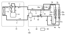
- FIG. 1 is a circuit diagram showing an example of the configuration of an air conditioner according to Embodiment 1.
- FIG. FIG. 2 is a schematic diagram for explaining the flow of refrigerant in the air conditioner of FIG. 1 in a cooling only operation mode;
- FIG. 2 is a schematic diagram for explaining the flow of refrigerant in a cooling main operation mode in the air conditioner of FIG. 1;
- FIG. 2 is a schematic diagram for explaining the flow of refrigerant in a heating only operation mode in the air conditioner of FIG. 1;
- FIG. 2 is a schematic diagram for explaining the flow of refrigerant in a heating main operation mode in the air conditioner of FIG. 1;
- FIG. 2 is a schematic diagram for explaining the flow of refrigerant in the partial load stop operation mode in the air conditioner of FIG. 1;
- Embodiment 1 A refrigeration cycle apparatus according to Embodiment 1 will be described.
- An air conditioner as a refrigeration cycle device will be described below as an example.
- An air conditioner which is a refrigerating cycle device, is installed in, for example, a building, an apartment building, etc., and can perform cooling operation or heating operation using a refrigerating cycle that circulates a refrigerant.
- the air conditioner according to Embodiment 1 can perform only cooling operation, only heating operation, or simultaneous cooling and heating operation for a plurality of air-conditioned spaces.
- FIG. 1 is a circuit diagram showing an example of the configuration of an air conditioner according to Embodiment 1.
- An air conditioner 100 according to Embodiment 1 includes a heat source side unit 10 , a plurality of load side units 20 , a relay unit 30 and a control device 40 .
- the example of FIG. 1 shows a case where the air conditioner 100 is composed of one heat source side unit 10, two load side units 20a and 20b, and one relay unit 30.
- FIG. 1 is a circuit diagram showing an example of the configuration of an air conditioner according to Embodiment 1.
- FIG. 1 An air conditioner 100 according to Embodiment 1 includes a heat source side unit 10 , a plurality of load side units 20 , a relay unit 30 and a control device 40 .
- the example of FIG. 1 shows a case where the air conditioner 100 is composed of one heat source side unit 10, two load side units 20a and 20b, and one relay unit 30.
- the heat source side unit 10 and the relay unit 30 are connected by the gas pipe 1 and the liquid pipe 2 .
- the relay unit 30 and the load side unit 20a are connected by the gas branch pipe 3a and the liquid branch pipe 4a, and the relay unit 30 and the load side unit 20b are connected by the gas branch pipe 3b and the liquid branch pipe 4b.
- a refrigerating cycle is formed by connecting the heat source side unit 10, the relay unit 30, and the load side units 20a and 20b with respective pipes.
- the number of load-side units 20 is not limited to this example, and may be three or more.
- the number of heat source side units 10 and relay units 30 may be, for example, two or more.
- the heat source side unit 10 is provided to supply heat to the load side unit 20 .
- the heat source side unit 10 includes a compressor 11 , a refrigerant flow switching device 12 , a heat source side heat exchanger 13 and an accumulator 14 .
- the compressor 11 sucks in a low-temperature, low-pressure gas refrigerant, compresses the refrigerant into a high-temperature, high-pressure state, and discharges it.
- the compressor 11 for example, an inverter compressor or the like is used, which can control the capacity, which is the amount of refrigerant delivered per unit time, by arbitrarily changing the drive frequency.
- a driving frequency of the compressor 11 is controlled by the control device 40 .
- the compressor 11 is not limited to the inverter type, and may be, for example, a constant speed type compressor or a compressor combining an inverter type and a constant speed type. Further, the compressor 11 may be of any type as long as it can compress the sucked refrigerant to a high pressure state, and may be of various types such as a reciprocating, rotary, scroll or screw type.
- the refrigerant flow switching device 12 is, for example, a four-way valve, and switches between cooling operation and heating operation by switching the direction of refrigerant flow. Switching of the refrigerant flow switching device 12 is controlled by the control device 40 . Note that the refrigerant flow switching device 12 is not limited to this example, and may be configured by combining other valves such as a two-way valve or a three-way valve.
- the heat source side heat exchanger 13 exchanges heat between a fluid such as outdoor air or water and the refrigerant. Specifically, the heat source side heat exchanger 13 functions as a condenser that radiates the heat of the refrigerant to the outdoor air to condense and liquefy the refrigerant during the cooling operation. Further, the heat source side heat exchanger 13 functions as an evaporator that evaporates and gasifies the refrigerant during heating operation and absorbs heat from the outdoor air as heat of vaporization.
- the heat source side unit 10 is provided with a blower (not shown) such as a heat source side fan for supplying outdoor air to the heat source side heat exchanger 13.
- a blower such as a heat source side fan for supplying outdoor air to the heat source side heat exchanger 13.
- the heat source side unit 10 When the heat source side heat exchanger 13 is a water-cooled heat exchanger, the heat source side unit 10 is provided with a water circulation pump (not shown) for circulating fluid such as water and supplying it to the heat source side heat exchanger 13.
- a water circulation pump (not shown) for circulating fluid such as water and supplying it to the heat source side heat exchanger 13.
- the accumulator 14 is provided on the low pressure side, which is the suction side of the compressor 11 .
- the accumulator 14 stores surplus refrigerant caused by the difference in operating conditions between cooling operation and heating operation, surplus refrigerant due to transient changes in operation, and the like. Note that the accumulator 14 may not necessarily be provided.
- the load-side units 20a and 20b supply heat from the heat source-side unit 10 to the cooling load or heating load, respectively, for cooling and heating.
- the load side unit 20a includes a load side expansion device 21a and a load side heat exchanger 22a.
- the load side unit 20b includes a load side expansion device 21b and a load side heat exchanger 22b.
- load-side unit 20 when there is no particular need to distinguish between the load-side units 20a and 20b, they will be simply referred to as "load-side unit 20".
- the load side expansion device 21a and the load side expansion device 21b have the same configuration, and the load side heat exchanger 22a and the load side heat exchanger 22b have the same configuration. Therefore, the load side expansion device 21a and the load side heat exchanger 22a will be described below as an example.
- the load-side expansion device 21a functions as a pressure reducing valve and an expansion valve, and adjusts the flow rate of the refrigerant to decompress and expand the refrigerant.
- the load-side expansion device 21a is composed of, for example, a valve whose opening degree can be controlled, such as an electronic expansion valve. In this case, the opening degree of the load side expansion device 21a is controlled by the control device 40.
- FIG. Note that the load-side expansion device 21a is not limited to this example, and other expansion devices such as capillary tubes may be used.
- the load-side heat exchanger 22a exchanges heat between the indoor air or a fluid such as water and the refrigerant. Specifically, the load-side heat exchanger 22a functions as an evaporator that evaporates and gasifies the refrigerant during the cooling operation and absorbs heat from the outdoor air as heat of vaporization. In addition, the load-side heat exchanger 22a functions as a condenser that radiates the heat of the refrigerant to the indoor air to condense and liquefy the refrigerant during the heating operation.
- the load-side unit 20a is generally provided with a blower (not shown) such as a load-side fan for supplying indoor air to the load-side heat exchanger 22a.
- the controller 40 controls the rotation speed of the load-side fan, thereby controlling the evaporating capacity or the condensing capacity of the load-side heat exchanger 22a.
- the relay unit 30 switches the flow of the refrigerant according to the operating conditions of the load-side unit 20 so that the low-temperature refrigerant is distributed to the load-side unit 20 that performs the cooling operation, and the high-temperature refrigerant is distributed to the load-side unit 20 that performs the heating operation.
- the relay unit 30 includes a gas-liquid separator 31, a first expansion device 32, a second expansion device 33, and three-way valves 34a and 34b.
- the three-way valves 34a and 34b are simply referred to as the "three-way valve 34".
- connection pipe 5 connects the gas side of the gas-liquid separator 31 and the three-way valves 34a and 34b, and is a pipe through which gas refrigerant flows.
- connection pipe 6 is a pipe that connects the liquid side of the gas-liquid separator 31 and the load side unit 20 and through which the liquid refrigerant flows.
- the relay pipe 7 is provided to relay the connection pipe 5 and the connection pipe 6 .
- the gas-liquid separator 31 is provided on the liquid pipe 2 and connected to the connection pipe 5 and the connection pipe 6 .
- the gas-liquid separator 31 separates the two-phase refrigerant flowing through the liquid pipe 2 into gas refrigerant and liquid refrigerant.
- the gas refrigerant separated by the gas-liquid separator 31 is supplied via the connecting pipe 5 to the three-way valves 34a and 34b.
- the liquid refrigerant separated by the gas-liquid separator 31 is supplied to the first expansion device 32 through the connecting pipe 6 .
- the first throttle device 32 is provided on the connecting pipe 6 .
- the first expansion device 32 functions as a pressure reducing valve and an expansion valve, and adjusts the flow rate of the refrigerant to decompress and expand the refrigerant.
- the first throttle device 32 is composed of, for example, a valve such as an electronic expansion valve whose degree of opening can be controlled. In this case, the opening degree of the first throttle device 32 is controlled by the control device 40 .
- the first expansion device 32 is not limited to this example, and other expansion devices such as capillary tubes may be used.
- the second throttle device 33 is provided on the relay pipe 7 .
- the second expansion device 33 functions as a pressure reducing valve and an expansion valve, and adjusts the flow rate of the refrigerant to decompress and expand the refrigerant.
- the second throttle device 33 is composed of, for example, a valve such as an electronic expansion valve whose degree of opening can be controlled. In this case, the opening degree of the second throttle device 33 is controlled by the control device 40 .
- the second expansion device 33 is not limited to this example, and other expansion devices such as capillary tubes may be used.
- the three-way valve 34 switches the direction of refrigerant flow according to the operating conditions of the load-side unit 20 .
- the three-way valves 34 are provided according to the number of load-side units 20, and in the example of FIG. 1, three-way valves 34a and 34b are provided to correspond to the load-side units 20a and 20b, respectively.
- the three-way valve 34 a is connected to the connection pipe 5 , the gas branch pipe 3 a and the gas pipe 1 .
- the three-way valve 34 b is connected to the connection pipe 5 , the gas branch pipe 3 b and the gas pipe 1 .
- the three-way valve 34a switches connection so that the gas branch pipe 3a communicates with either the gas pipe 1 or the connection pipe 5 according to the operating conditions of the load side unit 20a.
- the three-way valve 34a switches connection so that the gas branch pipe 3b communicates with either the gas pipe 1 or the connection pipe 5 according to the operating conditions of the load side unit 20b.
- the three-way valves 34a and 34b can also be set so that the gas branch pipes 3a and 3b are connected to neither the gas pipe 1 nor the connection pipe 5. Specifically, the three-way valve 34a switches the connection so that the gas branch pipe 3a is connected to neither the gas pipe 1 nor the connection pipe 5 when the operation of the load side unit 20a is stopped. Further, the three-way valve 34b switches the connection so that the gas branch pipe 3b is connected to neither the gas pipe 1 nor the connection pipe 5 when the operation of the load side unit 20b is stopped.
- control device 40 The control device 40 controls the entire air conditioner 100 .
- the control device 40 controls the refrigerant flow switching device 12, the load side expansion devices 21a and 21b, the first expansion device 32, the second expansion device 33, the three-way valves 34a and 34b, etc., according to the operation mode of the air conditioner 100.
- the control device 40 implements various functions by executing software on an arithmetic device such as a microcomputer, or is configured with hardware such as circuit devices that implement various functions.
- the air-conditioning apparatus 100 operates in one of the cooling-only operation, cooling-main operation, heating-only operation, and heating-main operation.
- the cooling-only operation is an operation in which all load-side units 20 perform cooling operation.
- the cooling-dominant operation is an operation that is performed when the cooling load of the load-side unit 20 that performs the cooling operation exceeds the heating load of the load-side unit 20 that performs the heating operation.
- the heating only operation is an operation in which all the load side units 20 perform the heating operation.
- the heating-dominant operation is an operation that is performed when the heating load of the load-side unit 20 that performs the heating operation exceeds the cooling load of the load-side unit 20 that performs the cooling operation.
- FIG. 2 is a schematic diagram for explaining the flow of refrigerant in the air conditioner of FIG. 1 in the cooling only operation mode.
- the cooling only operation mode all the load side units 20a and 20b perform cooling operation.
- the flow path indicated by a thick line is the refrigerant flow path during the cooling only operation mode, and the direction of flow of the refrigerant in the refrigerant flow path is indicated by arrows.
- the refrigerant flow switching device 12 in the heat source side unit 10 is switched so that the discharge side of the compressor 11 and the heat source side heat exchanger 13 are connected, and the suction side of the compressor 11 and the gas pipe 1 are connected.
- the three-way valves 34a and 34b are switched respectively so that the gas pipe 1 and the gas branch pipes 3a and 3b are connected.
- the low-temperature, low-pressure refrigerant is compressed by the compressor 11 and discharged as a high-temperature, high-pressure gas refrigerant.
- the high-temperature, high-pressure gas refrigerant discharged from the compressor 11 flows into the heat source side heat exchanger 13 via the refrigerant flow switching device 12 .
- the high-temperature, high-pressure gas refrigerant that has flowed into the heat source-side heat exchanger 13 is condensed while exchanging heat with outdoor air and releasing heat, and flows out of the heat-source-side heat exchanger 13 as a high-pressure liquid refrigerant.
- the high-pressure liquid refrigerant that has flowed out of the heat source side heat exchanger 13 passes through the liquid pipe 2 , flows out of the heat source side unit 10 , and flows into the relay unit 30 .
- the high-pressure liquid refrigerant that has flowed into the relay unit 30 flows through the gas-liquid separator 31 into the first expansion device 32, where it is decompressed and expanded to become intermediate-pressure liquid refrigerant.
- the intermediate-pressure liquid refrigerant After passing through the connection pipe 6 , the intermediate-pressure liquid refrigerant is branched to the liquid branch pipes 4 a and 4 b and flows out from the relay unit 30 .
- the liquid refrigerant flowing out of the relay unit 30 passes through the liquid branch pipes 4a and 4b and flows into the load side units 20a and 20b.
- the intermediate-pressure liquid refrigerant that has flowed into the load-side unit 20a is decompressed and expanded by the load-side expansion device 21a to become a low-temperature, low-pressure gas-liquid two-phase refrigerant, which flows into the load-side heat exchanger 22a.
- the low-temperature, low-pressure gas-liquid two-phase refrigerant that has flowed into the load-side heat exchanger 22a exchanges heat with the indoor air, absorbs heat, and evaporates to cool the indoor air, becoming a low-pressure gas refrigerant, and flows out of the load-side heat exchanger 22a.
- the low-pressure gas refrigerant that has flowed out of the load-side heat exchanger 22 a passes through the gas branch pipe 3 a, flows out of the load-side unit 20 a, and flows into the relay unit 30 .
- the intermediate-pressure liquid refrigerant that has flowed into the load-side unit 20b also becomes low-pressure gas refrigerant through the load-side expansion device 21b and the load-side heat exchanger 22b, like the refrigerant that has flowed into the load-side unit 20a. Then, the low-pressure gas refrigerant passes through the gas branch pipe 3b, flows out from the load-side unit 20b, and flows into the relay unit 30. As shown in FIG.
- the low-pressure gas refrigerant that has flowed into the relay unit 30 reaches the gas pipe 1 via the three-way valves 34 a and 34 b, flows out from the relay unit 30 , and then flows into the heat source side unit 10 .
- the low-pressure gas refrigerant that has flowed into the heat source side unit 10 passes through the refrigerant flow switching device 12 and the accumulator 14 and is sucked into the compressor 11 . Thereafter, the above-described circulation is repeated.
- FIG. 3 is a schematic diagram for explaining the flow of refrigerant in the air conditioner of FIG. 1 in the cooling main operation mode.
- the load side unit 20a performs cooling operation and the load side unit 20b performs heating operation will be described as an example.
- the flow path indicated by a thick line is the refrigerant flow path in the cooling main operation mode, and the direction of flow of the refrigerant in the refrigerant flow path is indicated by arrows.
- the refrigerant flow switching device 12 in the heat source side unit 10 is switched so that the discharge side of the compressor 11 and the heat source side heat exchanger 13 are connected, and the suction side of the compressor 11 and the gas pipe 1 are connected. Also, the three-way valve 34a is switched so that the gas pipe 1 and the gas branch pipe 3a are connected. The three-way valve 34b is switched so that the connection pipe 5 and the gas branch pipe 3b are connected.
- the low-temperature, low-pressure refrigerant is compressed by the compressor 11 and discharged as a high-temperature, high-pressure gas refrigerant.
- the high-temperature, high-pressure gas refrigerant discharged from the compressor 11 flows into the heat source side heat exchanger 13 via the refrigerant flow switching device 12 .
- the high-temperature, high-pressure gas refrigerant that has flowed into the heat source-side heat exchanger 13 is condensed while exchanging heat with outdoor air to release heat, and flows out of the heat-source-side heat exchanger 13 as a high-pressure gas-liquid two-phase refrigerant.
- the high-pressure gas-liquid two-phase refrigerant that has flowed out of the heat source side heat exchanger 13 passes through the liquid pipe 2 , flows out of the heat source side unit 10 , and flows into the relay unit 30 .
- the high-pressure gas-liquid two-phase refrigerant that has flowed into the relay unit 30 flows into the gas-liquid separator 31 and is separated into a high-pressure gas refrigerant and a high-pressure liquid refrigerant.
- the high-pressure gas refrigerant separated by the gas-liquid separator 31 passes through the connecting pipe 5, passes through the gas branch pipe 3b via the three-way valve 34b, and flows out from the relay unit 30.
- the high-pressure gas refrigerant that has flowed out of the relay unit 30 flows into the load side unit 20b.
- the high-pressure gas refrigerant that has flowed into the load-side unit 20b flows into the load-side heat exchanger 22b, heats the indoor air by condensing while exchanging heat with the room air and releasing heat, and becomes high-pressure liquid refrigerant and flows out of the load-side heat exchanger 22b.
- the high-pressure liquid refrigerant that has flowed out of the load-side heat exchanger 22b is decompressed and expanded by the load-side throttle device 21b to become an intermediate-pressure liquid refrigerant.
- the intermediate-pressure liquid refrigerant that has flowed into the relay unit 30 is divided after passing through the liquid branch pipe 4b, and one part flows out of the relay unit 30 after passing through the liquid branch pipe 4a.
- the intermediate-pressure liquid refrigerant that has flowed out of the relay unit 30 flows into the load-side unit 20a.
- the intermediate-pressure liquid refrigerant that has flowed into the load-side unit 20a is decompressed and expanded by the load-side throttle device 21a to become a low-temperature, low-pressure gas-liquid two-phase refrigerant, which flows into the load-side heat exchanger 22a.
- the low-temperature, low-pressure gas-liquid two-phase refrigerant that has flowed into the load-side heat exchanger 22a exchanges heat with the indoor air, absorbs heat, and evaporates to cool the indoor air, becoming a low-pressure gas refrigerant, and flows out of the load-side heat exchanger 22a.
- the low-pressure gas refrigerant that has flowed out of the load-side heat exchanger 22 a passes through the gas branch pipe 3 a, flows out of the load-side unit 20 a, and flows into the relay unit 30 .
- the low-pressure gas refrigerant that has flowed into the relay unit 30 reaches the gas pipe 1 via the three-way valve 34a.
- the high-pressure liquid refrigerant separated by the gas-liquid separator 31 flows into the first expansion device 32 after passing through the connecting pipe 6, where it is decompressed and expanded to become an intermediate-pressure liquid refrigerant.
- the intermediate-pressure liquid refrigerant that has flowed out of the first expansion device 32 flows into the relay unit 30 from the load-side unit 20 b , joins the intermediate-pressure liquid refrigerant that is branched, and passes through the relay pipe 7 .
- the intermediate-pressure liquid refrigerant passing through the relay pipe 7 is decompressed and expanded by the second expansion device 33 to become a low-pressure liquid refrigerant.
- the low-pressure liquid refrigerant reaches the gas pipe 1 , joins the low-pressure gas refrigerant passing through the gas pipe 1 via the three-way valve 34 a , and flows out from the relay unit 30 .
- the low-pressure refrigerant flowing out of the relay unit 30 flows into the heat source side unit 10 via the gas pipe 1 .
- the low-pressure refrigerant that has flowed into the heat source side unit 10 passes through the refrigerant flow switching device 12 and the accumulator 14 and is sucked into the compressor 11 . Thereafter, the above-described circulation is repeated.
- FIG. 4 is a schematic diagram for explaining the flow of refrigerant in the air conditioner of FIG. 1 in the heating only operation mode.
- the heating only operation mode all the load side units 20a and 20b perform heating operation.
- the flow path indicated by the thick line is the refrigerant flow path in the heating only operation mode, and the arrow indicates the flow direction of the refrigerant in the refrigerant flow path.
- the refrigerant flow switching device 12 in the heat source side unit 10 is switched so that the discharge side of the compressor 11 and the gas pipe 1 are connected, and the suction side of the compressor 11 and the heat source side heat exchanger 13 are connected.
- the three-way valves 34a and 34b are switched respectively so that the gas pipe 1 and the gas branch pipes 3a and 3b are connected.
- the second expansion device 33 is fully closed or slightly opened.
- the low-temperature, low-pressure refrigerant is compressed by the compressor 11 and discharged as a high-temperature, high-pressure gas refrigerant.
- the high-temperature, high-pressure gas refrigerant discharged from the compressor 11 flows out of the heat source side unit 10 via the refrigerant flow switching device 12 and the gas pipe 1 and flows into the relay unit 30 .
- the high-temperature, high-pressure gas refrigerant that has flowed into relay unit 30 passes through gas branch pipes 3a and 3b via three-way valves 34a and 34b, then flows out of relay unit 30 and into load-side units 20a and 20b.
- the high-temperature, high-pressure gas refrigerant that has flowed into the load-side unit 20a flows into the load-side heat exchanger 22a, heats the indoor air by condensing while exchanging heat with the indoor air and releasing heat, and becomes a high-pressure liquid refrigerant and flows out of the load-side heat exchanger 22a.
- the high-pressure liquid refrigerant that has flowed out of the load-side heat exchanger 22a is decompressed and expanded by the load-side throttle device 21a to become a low-pressure liquid refrigerant.
- the high-temperature, high-pressure gas refrigerant that has flowed into the load-side unit 20b also becomes low-pressure liquid refrigerant through the load-side heat exchanger 22b and the load-side expansion device 21b, like the refrigerant that has flowed into the load-side unit 20a. Then, the low-pressure liquid refrigerant passes through the liquid branch pipe 4b, flows out from the load-side unit 20b, and flows into the relay unit 30. As shown in FIG. The low-pressure liquid refrigerant that has flowed into the relay unit 30 flows out of the relay unit 30 via the gas-liquid separator 31 .
- the low-pressure liquid refrigerant that has flowed out of the relay unit 30 flows into the heat source side unit 10 via the liquid pipe 2 .
- the low-pressure liquid refrigerant that has flowed into the heat source side unit 10 flows into the heat source side heat exchanger 13 .
- the low-pressure liquid refrigerant that has flowed into the heat source-side heat exchanger 13 exchanges heat with outdoor air, absorbs heat, evaporates, and flows out of the heat source-side heat exchanger 13 as a low-temperature, low-pressure gas refrigerant.
- the low-pressure gas refrigerant that has flowed out of the heat source side heat exchanger 13 passes through the refrigerant flow switching device 12 and the accumulator 14 and is sucked into the compressor 11 . Thereafter, the above-described circulation is repeated.
- FIG. 5 is a schematic diagram for explaining the flow of refrigerant in the air conditioner of FIG. 1 in the heating main operation mode.
- the load side unit 20a performs the heating operation
- the load side unit 20b performs the cooling operation.
- the flow path indicated by the thick line is the refrigerant flow path in the heating main operation mode
- the arrow indicates the flow direction of the refrigerant in the refrigerant flow path.
- the refrigerant flow switching device 12 in the heat source side unit 10 is switched so that the discharge side of the compressor 11 and the gas pipe 1 are connected, and the suction side of the compressor 11 and the heat source side heat exchanger 13 are connected. Also, the three-way valve 34a is switched so that the gas pipe 1 and the gas branch pipe 3a are connected. The three-way valve 34b is switched so that the connection pipe 5 and the gas branch pipe 3b are connected.
- the low-temperature, low-pressure refrigerant is compressed by the compressor 11 and discharged as a high-temperature, high-pressure gas refrigerant.
- the high-temperature, high-pressure gas refrigerant discharged from the compressor 11 flows out of the heat source side unit 10 via the refrigerant flow switching device 12 and the gas pipe 1 and flows into the relay unit 30 .
- the high-temperature, high-pressure gas refrigerant that has flowed into the relay unit 30 passes through the gas branch pipe 3a via the three-way valve 34a, then flows out of the relay unit 30 and flows into the load side unit 20a.
- the high-temperature, high-pressure gas refrigerant that has flowed into the load-side unit 20a flows into the load-side heat exchanger 22a, heats the indoor air by condensing while exchanging heat with the indoor air and releasing heat, and becomes a high-pressure liquid refrigerant and flows out of the load-side heat exchanger 22a.
- the high-pressure liquid refrigerant that has flowed out of the load-side heat exchanger 22a is decompressed and expanded by the load-side expansion device 21a to become an intermediate-pressure liquid refrigerant.
- the intermediate-pressure liquid refrigerant that has flowed into the relay unit 30 flows out of the relay unit 30 after passing through the liquid branch pipe 4 a and then the liquid branch pipe 4 b.
- the intermediate-pressure liquid refrigerant that has flowed out of the relay unit 30 flows into the load-side unit 20b.
- the intermediate-pressure liquid refrigerant that has flowed into the load-side unit 20b is decompressed and expanded by the load-side throttle device 21b to become a low-temperature, low-pressure gas-liquid two-phase refrigerant, which flows into the load-side heat exchanger 22b.
- the low-temperature, low-pressure gas-liquid two-phase refrigerant that has flowed into the load-side heat exchanger 22b exchanges heat with the indoor air, absorbs heat, and evaporates to cool the indoor air, becoming a low-pressure gas refrigerant, and flows out of the load-side heat exchanger 22b.
- the low-pressure gas refrigerant that has flowed out of the load-side heat exchanger 22 b passes through the gas branch pipe 3 b, flows out of the load-side unit 20 b, and flows into the relay unit 30 .
- the low-pressure gas refrigerant that has flowed into the relay unit 30 reaches the connecting pipe 5 via the three-way valve 34b. Then, the low-pressure gas refrigerant flows out of the relay unit 30 via the gas-liquid separator 31 .
- the low-pressure liquid refrigerant that has flowed out of the relay unit 30 flows into the heat source side unit 10 via the liquid pipe 2 .
- the low-pressure liquid refrigerant that has flowed into the heat source side unit 10 flows into the heat source side heat exchanger 13 .
- the low-pressure liquid refrigerant that has flowed into the heat source-side heat exchanger 13 exchanges heat with outdoor air, absorbs heat, evaporates, and flows out of the heat source-side heat exchanger 13 as a low-temperature, low-pressure gas refrigerant.
- the low-pressure gas refrigerant that has flowed out of the heat source side heat exchanger 13 passes through the refrigerant flow switching device 12 and the accumulator 14 and is sucked into the compressor 11 . Thereafter, the above-described circulation is repeated.
- the air-conditioning apparatus 100 according to Embodiment 1 can also perform partial load stop operation in which cooling operation or heating operation is performed while any one of the plurality of load-side units 20 is stopped.
- FIG. 6 is a schematic diagram for explaining the refrigerant flow in the partial load stop operation mode in the air conditioner of FIG.
- the load-side unit 20a performs the cooling operation while the load-side unit 20b is stopped.
- the flow path indicated by the thick line is the refrigerant flow path in the partial load suspension operation mode, and the arrow indicates the flow direction of the refrigerant in the refrigerant flow path.
- the refrigerant flow switching device 12 in the heat source side unit 10 is switched so that the discharge side of the compressor 11 and the heat source side heat exchanger 13 are connected, and the suction side of the compressor 11 and the gas pipe 1 are connected.
- the three-way valve 34a is switched so that the gas pipe 1 and the gas branch pipe 3a are connected.
- the three-way valve 34b is set so that the gas branch pipe 3b is connected to neither the gas pipe 1 nor the connection pipe 5.
- the load side expansion device 21b provided in the load side unit 20b whose operation is stopped is closed.
- the low-temperature, low-pressure refrigerant is compressed by the compressor 11 and discharged as a high-temperature, high-pressure gas refrigerant.
- the high-temperature, high-pressure gas refrigerant discharged from the compressor 11 flows into the heat source side heat exchanger 13 via the refrigerant flow switching device 12 .
- the high-temperature, high-pressure gas refrigerant that has flowed into the heat source-side heat exchanger 13 is condensed while exchanging heat with outdoor air and releasing heat, and flows out of the heat-source-side heat exchanger 13 as a high-pressure liquid refrigerant.
- the high-pressure liquid refrigerant that has flowed out of the heat source side heat exchanger 13 passes through the liquid pipe 2 , flows out of the heat source side unit 10 , and flows into the relay unit 30 .
- the high-pressure liquid refrigerant that has flowed into the relay unit 30 flows through the gas-liquid separator 31 into the first expansion device 32, where it is decompressed and expanded to become intermediate-pressure liquid refrigerant.
- the intermediate-pressure liquid refrigerant After passing through the connection pipe 6 , the intermediate-pressure liquid refrigerant passes through the liquid branch pipe 4 a and flows out from the relay unit 30 .
- the liquid refrigerant flowing out of the relay unit 30 passes through the liquid branch pipe 4a and flows into the load side units 20a and 20b.
- the intermediate-pressure liquid refrigerant that has flowed into the load-side unit 20a is decompressed and expanded by the load-side expansion device 21a to become a low-temperature, low-pressure gas-liquid two-phase refrigerant, which flows into the load-side heat exchanger 22a.
- the low-temperature, low-pressure gas-liquid two-phase refrigerant that has flowed into the load-side heat exchanger 22a exchanges heat with the indoor air, absorbs heat, and evaporates to cool the indoor air, becoming a low-pressure gas refrigerant, and flows out of the load-side heat exchanger 22a.
- the low-pressure gas refrigerant that has flowed out of the load-side heat exchanger 22 a passes through the gas branch pipe 3 a, flows out of the load-side unit 20 a, and flows into the relay unit 30 .
- the low-pressure gas refrigerant that has flowed into the relay unit 30 reaches the gas pipe 1 via the three-way valve 34a, flows out of the relay unit 30, and then flows into the heat source side unit 10.
- the low-pressure gas refrigerant that has flowed into the heat source side unit 10 passes through the refrigerant flow switching device 12 and the accumulator 14 and is sucked into the compressor 11 . Thereafter, the above-described circulation is repeated.
- the load side expansion device 21b of the load side unit 20b whose operation is stopped is closed, thereby preventing the refrigerant from accumulating in the load side unit 20b. Therefore, it is possible to prevent shortage of refrigerant in the refrigeration cycle.
- the operating load-side unit 20 performs the cooling operation in the partial load stop operation mode
- this is not limited to this example.
- the operating load side unit 20 may perform cooling-dominant operation, heating-only operation, or heating-dominant operation.
- a plurality of three-way valves 34 are provided corresponding to a plurality of load-side units 20, and the refrigerant flow is switched according to the operating state.
- two solenoid valves are used for one load side unit, but in the first embodiment, one three-way valve 34 is used instead of the two solenoid valves. Therefore, the number of parts can be reduced compared to conventional air conditioners that perform simultaneous cooling and heating operation.
- the conventional heat source side unit provided with four check valves is exclusively for simultaneous cooling and heating models, but by providing the three-way valve 34 in the relay unit 30, the heat source side unit 10 can be configured without four check valves. Therefore, the heat source side unit 10 can share a circuit with a cooling/heating switching model that switches between the cooling operation and the heating operation.
- the present disclosure is not limited to the first embodiment described above, and various modifications and applications are possible without departing from the gist of the present disclosure.
- the refrigeration cycle device is the air conditioner 100
- the refrigeration cycle device is not limited to this, and the refrigeration cycle device may be a cooling device or a freezing device that cools a refrigerated or frozen warehouse or the like.
- the type of refrigerant used in the air conditioner 100 is not particularly limited.
- any of natural refrigerants such as carbon dioxide, hydrocarbons or helium, chlorine-free alternative refrigerants such as HFC410A, HFC407C or HFC404A, or Freon-based refrigerants such as R22 or R134a may be used.
Abstract
This refrigeration cycle device comprises: a heat source side unit having a compressor and a heat source side heat exchanger; a plurality of load-side units each having a throttle device and a load-side heat exchanger; and a relay unit connected between the heat source side unit and the load-side units and having a plurality of three-way valves that are provided corresponding to the load-side units so as to switch the flow of refrigerant, the relay unit distributing low-temperature refrigerant to a load-side unit that performs cooling operation and high-temperature refrigerant to a load-side unit that performs heating operation. The three-way valves switch the flow of refrigerant so that the refrigerant flowing out of the heat source side unit flows into the load-side unit, or the refrigerant flowing out of the load-side unit flows into the heat source side unit, depending on the operating conditions.
Description
本開示は、複数の空調対象空間に対して冷房運転および暖房運転を同時に行うことができる冷凍サイクル装置に関するものである。
The present disclosure relates to a refrigeration cycle device capable of simultaneously performing cooling operation and heating operation for a plurality of air-conditioned spaces.
従来、複数の空調対象空間に対して冷房運転および暖房運転を同時に行うことができる冷暖同時機種である空気調和装置が知られている(例えば、特許文献1参照)。特許文献1に記載の空気調和装置は、熱源側ユニット、中継ユニットおよび複数の負荷側ユニットで構成され、熱源側ユニットと中継ユニットとの間を2つの接続配管で接続している。
Conventionally, there is known an air conditioner that is a simultaneous cooling and heating model capable of simultaneously performing cooling operation and heating operation for a plurality of air-conditioned spaces (see, for example, Patent Document 1). The air conditioner described in Patent Document 1 is composed of a heat source side unit, a relay unit, and a plurality of load side units, and the heat source side unit and the relay unit are connected by two connecting pipes.
特許文献1に記載の空気調和装置において、中継ユニットには、冷房運転用と暖房運転用とで、接続される負荷側ユニット1台あたり最低2個必要となる複数の電磁弁が設けられている。この電磁弁は、逆流れを閉止することができない構造となっていることから、熱源側ユニットと中継ユニットとの間を流れる冷媒の流通方向を、冷房運転と暖房運転とで同一方向にする必要がある。そのため、熱源側ユニット内の冷媒配管には、4個の逆止弁が設けられている。このような構成により、冷房運転および暖房運転のいずれの場合においても、熱源側ユニットと中継ユニットとの間に接続された2つの接続配管内を流通する冷媒の流通方向が、互いに逆向きで常に一方向となり、空気調和装置の安定した運転が実現される。
In the air conditioner described in Patent Document 1, the relay unit is provided with a plurality of electromagnetic valves, one for cooling operation and one for heating operation, which requires at least two for each connected load side unit. Since this solenoid valve has a structure that cannot close the reverse flow, it is necessary to set the direction of the refrigerant flowing between the heat source side unit and the relay unit to be the same for cooling operation and heating operation. Therefore, the refrigerant piping in the heat source side unit is provided with four check valves. With such a configuration, in both the cooling operation and the heating operation, the direction of flow of the refrigerant flowing in the two connecting pipes connected between the heat source side unit and the relay unit is always opposite to each other, and stable operation of the air conditioner is realized.
しかしながら、特許文献1に記載の空気調和装置では、熱源側ユニットの4個の逆止弁と、中継ユニットの複数の電磁弁を含む、多数の弁が必要となるため、回路が複雑化するとともに、部品点数が増加する。そのため、コストの増加、サービス性の悪化、故障のリスクの増大、ならびに、回路中の弁の増加によって増大する冷媒圧力損失による性能の低下といった課題がある。
However, the air conditioner described in Patent Document 1 requires a large number of valves, including four check valves in the heat source side unit and multiple solenoid valves in the relay unit, which complicates the circuit and increases the number of parts. As a result, there are issues such as increased costs, poor serviceability, increased risk of failure, and decreased performance due to increased refrigerant pressure loss due to the increased number of valves in the circuit.
本開示は、上記従来の技術における課題に鑑みてなされたものであって、部品点数を削減することができるとともに、部品点数を削減した場合でも、安定した運転を行うことができる冷凍サイクル装置を提供することを目的とする。
The present disclosure has been made in view of the above-described problems in the conventional technology, and aims to provide a refrigeration cycle device that can reduce the number of parts and can perform stable operation even when the number of parts is reduced.
本開示に係る冷凍サイクル装置は、圧縮機および熱源側熱交換器を有する熱源側ユニットと、絞り装置および負荷側熱交換器をそれぞれ有する複数の負荷側ユニットと、前記熱源側ユニットと前記負荷側ユニットとの間に接続されるものであり、冷媒の流れを切り替える、前記負荷側ユニットに対応して設けられた複数の三方弁を有し、冷房運転を行う負荷側ユニットに対して低温の前記冷媒を分配し、暖房運転を行う負荷側ユニットに対して高温の前記冷媒を分配する中継ユニットとを備え、前記三方弁は、運転状況に応じて、前記熱源側ユニットから流出した冷媒が前記負荷側ユニットに流入するように、あるいは、前記負荷側ユニットから流出した冷媒が前記熱源側ユニットに流入するように、前記冷媒の流れを切り替えるものである。
A refrigeration cycle apparatus according to the present disclosure includes a heat source side unit having a compressor and a heat source side heat exchanger, a plurality of load side units each having a throttle device and a load side heat exchanger, and a relay unit connected between the heat source side unit and the load side unit, having a plurality of three-way valves provided corresponding to the load side units for switching the flow of refrigerant, and distributing the low temperature refrigerant to the load side unit performing cooling operation and distributing the high temperature refrigerant to the load side unit performing heating operation. The three-way valve switches the flow of the refrigerant so that the refrigerant flowing out of the heat source side unit flows into the load side unit or the refrigerant flowing out of the load side unit flows into the heat source side unit, depending on the operating conditions.
本開示によれば、複数の負荷側ユニットに対応して複数の三方弁が設けられ、運転状態に応じて冷媒の流れが切り替えられる。これにより、従来の冷凍サイクル装置の熱源側ユニットに設けられた4個の逆止弁が不要となるとともに、中継ユニットの複数の電磁弁が三方弁に置き替えられるため、従来の冷凍サイクル装置と比較して、部品点数を削減することができる。また、部品点数の削減によって圧力損失を低減できるため、性能低下を抑制し、安定した運転を行うことができる。
According to the present disclosure, a plurality of three-way valves are provided corresponding to a plurality of load side units, and the refrigerant flow is switched according to the operating state. This eliminates the need for the four check valves provided in the heat source side unit of the conventional refrigeration cycle device, and replaces the plurality of solenoid valves of the relay unit with three-way valves, so the number of parts can be reduced compared to the conventional refrigeration cycle device. In addition, since pressure loss can be reduced by reducing the number of parts, deterioration in performance can be suppressed and stable operation can be performed.
以下、本開示の実施の形態について、図面を参照して説明する。本開示は、以下の実施の形態に限定されるものではなく、本開示の主旨を逸脱しない範囲で種々に変形することが可能である。また、本開示は、以下の各実施の形態に示す構成のうち、組合せ可能な構成のあらゆる組合せを含むものである。また、温度および圧力等の高低については、特に絶対的な値との関係で高低等が定まっているものではなく、システムおよび装置等における状態および動作等において相対的に定まるものとする。また、各図において、同一の符号を付したものは、同一のまたはこれに相当するものであり、これは明細書の全文において共通している。
Hereinafter, embodiments of the present disclosure will be described with reference to the drawings. The present disclosure is not limited to the following embodiments, and various modifications can be made without departing from the gist of the present disclosure. In addition, the present disclosure includes all combinations of configurations that can be combined among the configurations shown in the following embodiments. Moreover, the levels of temperature, pressure, etc., are not determined in relation to absolute values, but are relatively determined by the states and operations of systems and devices. Also, in each figure, the same reference numerals denote the same or corresponding parts, which are common throughout the specification.
実施の形態1.
本実施の形態1に係る冷凍サイクル装置について説明する。以下では、冷凍サイクル装置としての空気調和装置を例にとって説明する。この冷凍サイクル装置である空気調和装置は、例えばビル、マンション等に設置され、冷媒を循環させる冷凍サイクルを利用して、冷房運転または暖房運転を実行できるものである。特に、本実施の形態1に係る空気調和装置は、複数の空調対象空間に対して冷房運転のみ、暖房運転のみ、または、冷暖房同時運転を行うことができる。Embodiment 1.
A refrigeration cycle apparatus according toEmbodiment 1 will be described. An air conditioner as a refrigeration cycle device will be described below as an example. An air conditioner, which is a refrigerating cycle device, is installed in, for example, a building, an apartment building, etc., and can perform cooling operation or heating operation using a refrigerating cycle that circulates a refrigerant. In particular, the air conditioner according to Embodiment 1 can perform only cooling operation, only heating operation, or simultaneous cooling and heating operation for a plurality of air-conditioned spaces.
本実施の形態1に係る冷凍サイクル装置について説明する。以下では、冷凍サイクル装置としての空気調和装置を例にとって説明する。この冷凍サイクル装置である空気調和装置は、例えばビル、マンション等に設置され、冷媒を循環させる冷凍サイクルを利用して、冷房運転または暖房運転を実行できるものである。特に、本実施の形態1に係る空気調和装置は、複数の空調対象空間に対して冷房運転のみ、暖房運転のみ、または、冷暖房同時運転を行うことができる。
A refrigeration cycle apparatus according to
[空気調和装置100の構成]
図1は、本実施の形態1に係る空気調和装置の構成の一例を示す回路図である。本実施の形態1に係る空気調和装置100は、熱源側ユニット10、複数の負荷側ユニット20、中継ユニット30および制御装置40を含んで構成されている。図1の例では、空気調和装置100が1台の熱源側ユニット10と、2台の負荷側ユニット20aおよび20bと、1台の中継ユニット30で構成される場合を示している。 [Configuration of air conditioner 100]
FIG. 1 is a circuit diagram showing an example of the configuration of an air conditioner according toEmbodiment 1. FIG. An air conditioner 100 according to Embodiment 1 includes a heat source side unit 10 , a plurality of load side units 20 , a relay unit 30 and a control device 40 . The example of FIG. 1 shows a case where the air conditioner 100 is composed of one heat source side unit 10, two load side units 20a and 20b, and one relay unit 30. FIG.
図1は、本実施の形態1に係る空気調和装置の構成の一例を示す回路図である。本実施の形態1に係る空気調和装置100は、熱源側ユニット10、複数の負荷側ユニット20、中継ユニット30および制御装置40を含んで構成されている。図1の例では、空気調和装置100が1台の熱源側ユニット10と、2台の負荷側ユニット20aおよび20bと、1台の中継ユニット30で構成される場合を示している。 [Configuration of air conditioner 100]
FIG. 1 is a circuit diagram showing an example of the configuration of an air conditioner according to
空気調和装置100では、熱源側ユニット10と中継ユニット30とがガス配管1および液配管2で接続されている。また、中継ユニット30と負荷側ユニット20aとがガス枝管3aおよび液枝管4aで接続され、中継ユニット30と負荷側ユニット20bとがガス枝管3bおよび液枝管4bで接続されている。このように、熱源側ユニット10と、中継ユニット30と、負荷側ユニット20aおよび20bとがそれぞれの配管で接続されることにより、冷凍サイクルが形成されている。なお、負荷側ユニット20の台数は、この例に限られず、3台以上であってもよい。また、熱源側ユニット10および中継ユニット30の台数についても、例えば2台以上であってもよい。
In the air conditioner 100 , the heat source side unit 10 and the relay unit 30 are connected by the gas pipe 1 and the liquid pipe 2 . The relay unit 30 and the load side unit 20a are connected by the gas branch pipe 3a and the liquid branch pipe 4a, and the relay unit 30 and the load side unit 20b are connected by the gas branch pipe 3b and the liquid branch pipe 4b. Thus, a refrigerating cycle is formed by connecting the heat source side unit 10, the relay unit 30, and the load side units 20a and 20b with respective pipes. Note that the number of load-side units 20 is not limited to this example, and may be three or more. Also, the number of heat source side units 10 and relay units 30 may be, for example, two or more.
(熱源側ユニット10)
熱源側ユニット10は、負荷側ユニット20に熱を供給するために設けられている。熱源側ユニット10は、圧縮機11、冷媒流路切替装置12、熱源側熱交換器13およびアキュムレータ14を備えている。 (Heat source side unit 10)
The heatsource side unit 10 is provided to supply heat to the load side unit 20 . The heat source side unit 10 includes a compressor 11 , a refrigerant flow switching device 12 , a heat source side heat exchanger 13 and an accumulator 14 .
熱源側ユニット10は、負荷側ユニット20に熱を供給するために設けられている。熱源側ユニット10は、圧縮機11、冷媒流路切替装置12、熱源側熱交換器13およびアキュムレータ14を備えている。 (Heat source side unit 10)
The heat
圧縮機11は、低温低圧のガス冷媒を吸入し、その冷媒を圧縮して高温高圧の状態にして吐出する。圧縮機11として、例えば、駆動周波数を任意に変化させることにより、単位時間あたりの冷媒送出量である容量を制御することが可能なインバータ圧縮機等が用いられる。圧縮機11の駆動周波数は、制御装置40によって制御される。
The compressor 11 sucks in a low-temperature, low-pressure gas refrigerant, compresses the refrigerant into a high-temperature, high-pressure state, and discharges it. As the compressor 11, for example, an inverter compressor or the like is used, which can control the capacity, which is the amount of refrigerant delivered per unit time, by arbitrarily changing the drive frequency. A driving frequency of the compressor 11 is controlled by the control device 40 .
なお、圧縮機11は、インバータタイプに限られず、例えば一定速タイプの圧縮機、あるいは、インバータタイプと一定速タイプとを組み合わせた圧縮機であってもよい。また、圧縮機11は、吸入した冷媒を高圧状態に圧縮することができるものであればよく、例えば、レシプロ、ロータリー、スクロールあるいはスクリュー等の各種タイプで構成される。
The compressor 11 is not limited to the inverter type, and may be, for example, a constant speed type compressor or a compressor combining an inverter type and a constant speed type. Further, the compressor 11 may be of any type as long as it can compress the sucked refrigerant to a high pressure state, and may be of various types such as a reciprocating, rotary, scroll or screw type.
冷媒流路切替装置12は、例えば四方弁であり、冷媒の流れる方向を切り替えることにより、冷房運転および暖房運転の切り替えを行う。冷媒流路切替装置12の切り替えは、制御装置40によって制御される。なお、冷媒流路切替装置12は、この例に限られず、例えば二方弁または三方弁等の他の弁を組み合わせることによって構成されてもよい。
The refrigerant flow switching device 12 is, for example, a four-way valve, and switches between cooling operation and heating operation by switching the direction of refrigerant flow. Switching of the refrigerant flow switching device 12 is controlled by the control device 40 . Note that the refrigerant flow switching device 12 is not limited to this example, and may be configured by combining other valves such as a two-way valve or a three-way valve.
熱源側熱交換器13は、室外空気または水等の流体と冷媒との間で熱交換を行う。具体的には、熱源側熱交換器13は、冷房運転の際に、冷媒の熱を室外空気に放熱して冷媒を凝縮させて液化する凝縮器として機能する。また、熱源側熱交換器13は、暖房運転の際に、冷媒を蒸発させてガス化し、気化熱として室外空気から熱を吸収する蒸発器として機能する。
The heat source side heat exchanger 13 exchanges heat between a fluid such as outdoor air or water and the refrigerant. Specifically, the heat source side heat exchanger 13 functions as a condenser that radiates the heat of the refrigerant to the outdoor air to condense and liquefy the refrigerant during the cooling operation. Further, the heat source side heat exchanger 13 functions as an evaporator that evaporates and gasifies the refrigerant during heating operation and absorbs heat from the outdoor air as heat of vaporization.
熱源側熱交換器13が空冷式熱交換器である場合、熱源側ユニット10には、室外空気を熱源側熱交換器13に供給するための熱源側ファン等の図示しない送風機が設けられる。そして、制御装置40によって熱源側ファンの回転数が制御されることにより、熱源側熱交換器13の凝縮能力または蒸発能力が制御される。
When the heat source side heat exchanger 13 is an air-cooled heat exchanger, the heat source side unit 10 is provided with a blower (not shown) such as a heat source side fan for supplying outdoor air to the heat source side heat exchanger 13. By controlling the rotation speed of the heat source side fan by the control device 40, the condensing ability or evaporation ability of the heat source side heat exchanger 13 is controlled.
また、熱源側熱交換器13が水冷式熱交換器である場合、熱源側ユニット10には、水等の流体を循環させて熱源側熱交換器13に供給するための図示しない水循環ポンプが設けられる。そして、制御装置40によって水循環ポンプの回転数が制御されることにより、熱源側熱交換器13の凝縮能力または蒸発能力が制御される。
When the heat source side heat exchanger 13 is a water-cooled heat exchanger, the heat source side unit 10 is provided with a water circulation pump (not shown) for circulating fluid such as water and supplying it to the heat source side heat exchanger 13. By controlling the rotational speed of the water circulation pump by the control device 40, the condensing ability or the evaporating ability of the heat source side heat exchanger 13 is controlled.
アキュムレータ14は、圧縮機11の吸入側である低圧側に設けられている。アキュムレータ14は、冷房運転と暖房運転との運転状態の違いによって生じる余剰冷媒、および過渡的な運転の変化に対する余剰冷媒等を貯留する。なお、アキュムレータ14は、必ずしも設けられてなくてもよい。
The accumulator 14 is provided on the low pressure side, which is the suction side of the compressor 11 . The accumulator 14 stores surplus refrigerant caused by the difference in operating conditions between cooling operation and heating operation, surplus refrigerant due to transient changes in operation, and the like. Note that the accumulator 14 may not necessarily be provided.
(負荷側ユニット20aおよび20b)
負荷側ユニット20aおよび20bは、それぞれ、冷房負荷または暖房負荷に対して、熱源側ユニット10からの熱を供給し、冷房および暖房を行うものである。負荷側ユニット20aは、負荷側絞り装置21aおよび負荷側熱交換器22aを備えている。負荷側ユニット20bは、負荷側絞り装置21bおよび負荷側熱交換器22bを備えている。 (Load side units 20a and 20b)
The load- side units 20a and 20b supply heat from the heat source-side unit 10 to the cooling load or heating load, respectively, for cooling and heating. The load side unit 20a includes a load side expansion device 21a and a load side heat exchanger 22a. The load side unit 20b includes a load side expansion device 21b and a load side heat exchanger 22b.
負荷側ユニット20aおよび20bは、それぞれ、冷房負荷または暖房負荷に対して、熱源側ユニット10からの熱を供給し、冷房および暖房を行うものである。負荷側ユニット20aは、負荷側絞り装置21aおよび負荷側熱交換器22aを備えている。負荷側ユニット20bは、負荷側絞り装置21bおよび負荷側熱交換器22bを備えている。 (Load
The load-
なお、以下の説明において、負荷側ユニット20aおよび20bを特に区別する必要がない場合には、単に「負荷側ユニット20」と適宜称して説明する。また、負荷側絞り装置21aおよび負荷側絞り装置21bは同一の構成であり、負荷側熱交換器22aおよび負荷側熱交換器22bは同一の構成であるため、以下では、負荷側絞り装置21aおよび負荷側熱交換器22aを例にとって説明する。
In the following description, when there is no particular need to distinguish between the load- side units 20a and 20b, they will be simply referred to as "load-side unit 20". The load side expansion device 21a and the load side expansion device 21b have the same configuration, and the load side heat exchanger 22a and the load side heat exchanger 22b have the same configuration. Therefore, the load side expansion device 21a and the load side heat exchanger 22a will be described below as an example.
負荷側絞り装置21aは、減圧弁および膨張弁としての機能を有し、冷媒の流量を調整することによって冷媒を減圧して膨張させる。負荷側絞り装置21aは、例えば、電子式膨張弁等の開度の制御が可能な弁で構成される。この場合、負荷側絞り装置21aの開度は、制御装置40によって制御される。なお、負荷側絞り装置21aは、この例に限られず、例えば毛細管等の他の絞り装置が用いられてもよい。
The load-side expansion device 21a functions as a pressure reducing valve and an expansion valve, and adjusts the flow rate of the refrigerant to decompress and expand the refrigerant. The load-side expansion device 21a is composed of, for example, a valve whose opening degree can be controlled, such as an electronic expansion valve. In this case, the opening degree of the load side expansion device 21a is controlled by the control device 40. FIG. Note that the load-side expansion device 21a is not limited to this example, and other expansion devices such as capillary tubes may be used.
負荷側熱交換器22aは、室内空気または水等の流体と冷媒との間で熱交換を行う。具体的には、負荷側熱交換器22aは、冷房運転の際に、冷媒を蒸発させてガス化し、気化熱として室外空気から熱を吸収する蒸発器として機能する。また、負荷側熱交換器22aは、暖房運転の際に、冷媒の熱を室内空気に放熱して冷媒を凝縮させて液化する凝縮器として機能する。
The load-side heat exchanger 22a exchanges heat between the indoor air or a fluid such as water and the refrigerant. Specifically, the load-side heat exchanger 22a functions as an evaporator that evaporates and gasifies the refrigerant during the cooling operation and absorbs heat from the outdoor air as heat of vaporization. In addition, the load-side heat exchanger 22a functions as a condenser that radiates the heat of the refrigerant to the indoor air to condense and liquefy the refrigerant during the heating operation.
本実施の形態1のように、冷凍サイクル装置が空気調和装置100である場合、一般的には、負荷側ユニット20aには、室内空気を負荷側熱交換器22aに供給するための負荷側ファン等の図示しない送風機が設けられる。そして、制御装置40によって負荷側ファンの回転数が制御されることにより、負荷側熱交換器22aの蒸発能力または凝縮能力が制御される。
As in Embodiment 1, when the refrigeration cycle device is the air conditioner 100, the load-side unit 20a is generally provided with a blower (not shown) such as a load-side fan for supplying indoor air to the load-side heat exchanger 22a. The controller 40 controls the rotation speed of the load-side fan, thereby controlling the evaporating capacity or the condensing capacity of the load-side heat exchanger 22a.
(中継ユニット30)
中継ユニット30は、冷房運転を実施する負荷側ユニット20には低温の冷媒を分配し、暖房運転を実施する負荷側ユニット20には高温の冷媒を分配するように、負荷側ユニット20の運転状況に応じて冷媒の流れを切り替えるものである。 (relay unit 30)
Therelay unit 30 switches the flow of the refrigerant according to the operating conditions of the load-side unit 20 so that the low-temperature refrigerant is distributed to the load-side unit 20 that performs the cooling operation, and the high-temperature refrigerant is distributed to the load-side unit 20 that performs the heating operation.
中継ユニット30は、冷房運転を実施する負荷側ユニット20には低温の冷媒を分配し、暖房運転を実施する負荷側ユニット20には高温の冷媒を分配するように、負荷側ユニット20の運転状況に応じて冷媒の流れを切り替えるものである。 (relay unit 30)
The
中継ユニット30は、気液分離器31、第1絞り装置32、第2絞り装置33、ならびに、三方弁34aおよび34bを備えている。なお、以下の説明において、三方弁34aおよび34bを特に区別する必要がない場合には、単に「三方弁34」と適宜称して説明する。
The relay unit 30 includes a gas-liquid separator 31, a first expansion device 32, a second expansion device 33, and three- way valves 34a and 34b. In the following description, when there is no particular need to distinguish between the three- way valves 34a and 34b, the three- way valves 34a and 34b are simply referred to as the "three-way valve 34".
また、中継ユニット30には、接続配管5、接続配管6および中継配管7が設けられている。接続配管5は、気液分離器31のガス側と三方弁34aおよび34bとを接続し、ガス冷媒が流れる配管である。接続配管6は、気液分離器31の液側と負荷側ユニット20とを接続し、液冷媒が流れる配管である。中継配管7は、接続配管5と接続配管6とを中継するために設けられている。
In addition, the connection pipe 5, the connection pipe 6, and the relay pipe 7 are provided in the relay unit 30. The connection pipe 5 connects the gas side of the gas-liquid separator 31 and the three- way valves 34a and 34b, and is a pipe through which gas refrigerant flows. The connection pipe 6 is a pipe that connects the liquid side of the gas-liquid separator 31 and the load side unit 20 and through which the liquid refrigerant flows. The relay pipe 7 is provided to relay the connection pipe 5 and the connection pipe 6 .
気液分離器31は、液配管2に設けられ、接続配管5および接続配管6が接続されている。気液分離器31は、液配管2を流れてくる二相冷媒をガス冷媒と液冷媒とに分離させる。気液分離器31で分離されたガス冷媒は、接続配管5を介して三方弁34aおよび34bに供給される。また、気液分離器31で分離された液冷媒は、接続配管6を介して第1絞り装置32に供給される。
The gas-liquid separator 31 is provided on the liquid pipe 2 and connected to the connection pipe 5 and the connection pipe 6 . The gas-liquid separator 31 separates the two-phase refrigerant flowing through the liquid pipe 2 into gas refrigerant and liquid refrigerant. The gas refrigerant separated by the gas-liquid separator 31 is supplied via the connecting pipe 5 to the three- way valves 34a and 34b. Also, the liquid refrigerant separated by the gas-liquid separator 31 is supplied to the first expansion device 32 through the connecting pipe 6 .
第1絞り装置32は、接続配管6に設けられている。第1絞り装置32は、減圧弁および膨張弁としての機能を有し、冷媒の流量を調整することによって冷媒を減圧して膨張させる。第1絞り装置32は、例えば、電子式膨張弁等の開度の制御が可能な弁で構成される。この場合、第1絞り装置32の開度は、制御装置40によって制御される。なお、第1絞り装置32は、この例に限られず、例えば毛細管等の他の絞り装置が用いられてもよい。
The first throttle device 32 is provided on the connecting pipe 6 . The first expansion device 32 functions as a pressure reducing valve and an expansion valve, and adjusts the flow rate of the refrigerant to decompress and expand the refrigerant. The first throttle device 32 is composed of, for example, a valve such as an electronic expansion valve whose degree of opening can be controlled. In this case, the opening degree of the first throttle device 32 is controlled by the control device 40 . The first expansion device 32 is not limited to this example, and other expansion devices such as capillary tubes may be used.
第2絞り装置33は、中継配管7に設けられている。第2絞り装置33は、減圧弁および膨張弁としての機能を有し、冷媒の流量を調整することによって冷媒を減圧して膨張させる。第2絞り装置33は、例えば、電子式膨張弁等の開度の制御が可能な弁で構成される。この場合、第2絞り装置33の開度は、制御装置40によって制御される。なお、第2絞り装置33は、この例に限られず、例えば毛細管等の他の絞り装置が用いられてもよい。
The second throttle device 33 is provided on the relay pipe 7 . The second expansion device 33 functions as a pressure reducing valve and an expansion valve, and adjusts the flow rate of the refrigerant to decompress and expand the refrigerant. The second throttle device 33 is composed of, for example, a valve such as an electronic expansion valve whose degree of opening can be controlled. In this case, the opening degree of the second throttle device 33 is controlled by the control device 40 . The second expansion device 33 is not limited to this example, and other expansion devices such as capillary tubes may be used.
三方弁34は、負荷側ユニット20の運転状況に応じて冷媒の流れる方向を切り替える。三方弁34は、負荷側ユニット20の台数に応じて設けられ、図1の例では、負荷側ユニット20aおよび20bに対応するように、三方弁34aおよび34bがそれぞれ設けられている。三方弁34aは、接続配管5、ガス枝管3aおよびガス配管1と接続されている。三方弁34bは、接続配管5、ガス枝管3bおよびガス配管1と接続されている。
The three-way valve 34 switches the direction of refrigerant flow according to the operating conditions of the load-side unit 20 . The three-way valves 34 are provided according to the number of load-side units 20, and in the example of FIG. 1, three- way valves 34a and 34b are provided to correspond to the load- side units 20a and 20b, respectively. The three-way valve 34 a is connected to the connection pipe 5 , the gas branch pipe 3 a and the gas pipe 1 . The three-way valve 34 b is connected to the connection pipe 5 , the gas branch pipe 3 b and the gas pipe 1 .
具体的には、三方弁34aは、負荷側ユニット20aの運転状況に応じて、ガス枝管3aがガス配管1および接続配管5のいずれかと連通するように、接続を切り替える。また、三方弁34aは、負荷側ユニット20bの運転状況に応じて、ガス枝管3bがガス配管1および接続配管5のいずれかと連通するように、接続を切り替える。
Specifically, the three-way valve 34a switches connection so that the gas branch pipe 3a communicates with either the gas pipe 1 or the connection pipe 5 according to the operating conditions of the load side unit 20a. In addition, the three-way valve 34a switches connection so that the gas branch pipe 3b communicates with either the gas pipe 1 or the connection pipe 5 according to the operating conditions of the load side unit 20b.
なお、三方弁34aおよび34bは、ガス枝管3aおよび3bがガス配管1と接続配管5とのいずれとも接続されないように設定することもできる。具体的には、三方弁34aは、負荷側ユニット20aの運転が停止される場合に、ガス枝管3aがガス配管1と接続配管5とのいずれとも接続されないように、接続を切り替える。また、三方弁34bは、負荷側ユニット20bの運転が停止される場合に、ガス枝管3bがガス配管1と接続配管5とのいずれとも接続されないように、接続を切り替える。
The three- way valves 34a and 34b can also be set so that the gas branch pipes 3a and 3b are connected to neither the gas pipe 1 nor the connection pipe 5. Specifically, the three-way valve 34a switches the connection so that the gas branch pipe 3a is connected to neither the gas pipe 1 nor the connection pipe 5 when the operation of the load side unit 20a is stopped. Further, the three-way valve 34b switches the connection so that the gas branch pipe 3b is connected to neither the gas pipe 1 nor the connection pipe 5 when the operation of the load side unit 20b is stopped.
(制御装置40)
制御装置40は、この空気調和装置100全体を制御する。例えば、制御装置40は、空気調和装置100の運転モードに応じて、冷媒流路切替装置12、負荷側絞り装置21aおよび21b、第1絞り装置32、第2絞り装置33、ならびに、三方弁34aおよび34b等を制御する。制御装置40は、マイクロコンピュータなどの演算装置上でソフトウェアを実行することにより各種機能が実現され、もしくは各種機能を実現する回路デバイスなどのハードウェア等で構成されている。 (control device 40)
Thecontrol device 40 controls the entire air conditioner 100 . For example, the control device 40 controls the refrigerant flow switching device 12, the load side expansion devices 21a and 21b, the first expansion device 32, the second expansion device 33, the three- way valves 34a and 34b, etc., according to the operation mode of the air conditioner 100. The control device 40 implements various functions by executing software on an arithmetic device such as a microcomputer, or is configured with hardware such as circuit devices that implement various functions.
制御装置40は、この空気調和装置100全体を制御する。例えば、制御装置40は、空気調和装置100の運転モードに応じて、冷媒流路切替装置12、負荷側絞り装置21aおよび21b、第1絞り装置32、第2絞り装置33、ならびに、三方弁34aおよび34b等を制御する。制御装置40は、マイクロコンピュータなどの演算装置上でソフトウェアを実行することにより各種機能が実現され、もしくは各種機能を実現する回路デバイスなどのハードウェア等で構成されている。 (control device 40)
The
[空気調和装置100の冷媒動作]
次に、上記構成を有する空気調和装置100における各種運転モードでの冷媒の動作について説明する。本実施の形態1に係る空気調和装置100は、全冷房運転、冷房主体運転、全暖房運転および暖房主体運転のいずれかの運転モードによる運転を行う。 [Refrigerant operation of air conditioner 100]
Next, the operation of the refrigerant in various operation modes in theair conditioner 100 having the above configuration will be described. The air-conditioning apparatus 100 according to Embodiment 1 operates in one of the cooling-only operation, cooling-main operation, heating-only operation, and heating-main operation.
次に、上記構成を有する空気調和装置100における各種運転モードでの冷媒の動作について説明する。本実施の形態1に係る空気調和装置100は、全冷房運転、冷房主体運転、全暖房運転および暖房主体運転のいずれかの運転モードによる運転を行う。 [Refrigerant operation of air conditioner 100]
Next, the operation of the refrigerant in various operation modes in the
全冷房運転は、すべての負荷側ユニット20が冷房運転を行う運転である。冷房主体運転は、冷房運転を行う負荷側ユニット20の冷房負荷が、暖房運転を行う負荷側ユニット20の暖房負荷を上回る場合に行われる運転である。全暖房運転は、すべての負荷側ユニット20が暖房運転を行う運転である。暖房主体運転は、暖房運転を行う負荷側ユニット20の暖房負荷が、冷房運転を行う負荷側ユニット20の冷房負荷を上回る場合に行われる運転である。
The cooling-only operation is an operation in which all load-side units 20 perform cooling operation. The cooling-dominant operation is an operation that is performed when the cooling load of the load-side unit 20 that performs the cooling operation exceeds the heating load of the load-side unit 20 that performs the heating operation. The heating only operation is an operation in which all the load side units 20 perform the heating operation. The heating-dominant operation is an operation that is performed when the heating load of the load-side unit 20 that performs the heating operation exceeds the cooling load of the load-side unit 20 that performs the cooling operation.
(全冷房運転モード)
図2は、図1の空気調和装置における全冷房運転モード時の冷媒の流れについて説明するための概略図である。全冷房運転モードでは、すべての負荷側ユニット20aおよび20bが冷房運転を行う。図2において、太線で示す流路が全冷房運転モード時の冷媒流路であり、冷媒流路中の冷媒の流れ方向を矢印で示す。 (cooling only operation mode)
FIG. 2 is a schematic diagram for explaining the flow of refrigerant in the air conditioner of FIG. 1 in the cooling only operation mode. In the cooling only operation mode, all the load side units 20a and 20b perform cooling operation. In FIG. 2 , the flow path indicated by a thick line is the refrigerant flow path during the cooling only operation mode, and the direction of flow of the refrigerant in the refrigerant flow path is indicated by arrows.
図2は、図1の空気調和装置における全冷房運転モード時の冷媒の流れについて説明するための概略図である。全冷房運転モードでは、すべての負荷側ユニット20aおよび20bが冷房運転を行う。図2において、太線で示す流路が全冷房運転モード時の冷媒流路であり、冷媒流路中の冷媒の流れ方向を矢印で示す。 (cooling only operation mode)
FIG. 2 is a schematic diagram for explaining the flow of refrigerant in the air conditioner of FIG. 1 in the cooling only operation mode. In the cooling only operation mode, all the
全冷房運転モードでは、まず、熱源側ユニット10における冷媒流路切替装置12は、圧縮機11の吐出側と熱源側熱交換器13とが接続され、圧縮機11の吸入側とガス配管1とが接続されるように切り替えられる。また、三方弁34aおよび34bは、ガス配管1とガス枝管3aおよび3bとが接続されるように、それぞれ切り替えられる。
In the cooling only operation mode, first, the refrigerant flow switching device 12 in the heat source side unit 10 is switched so that the discharge side of the compressor 11 and the heat source side heat exchanger 13 are connected, and the suction side of the compressor 11 and the gas pipe 1 are connected. In addition, the three- way valves 34a and 34b are switched respectively so that the gas pipe 1 and the gas branch pipes 3a and 3b are connected.
低温低圧の冷媒は、圧縮機11によって圧縮され、高温高圧のガス冷媒となって吐出される。圧縮機11から吐出された高温高圧のガス冷媒は、冷媒流路切替装置12を介して熱源側熱交換器13に流入する。熱源側熱交換器13に流入した高温高圧のガス冷媒は、室外空気と熱交換して放熱しながら凝縮し、高圧の液冷媒となって熱源側熱交換器13から流出する。熱源側熱交換器13から流出した高圧の液冷媒は、液配管2を通過して熱源側ユニット10から流出し、中継ユニット30に流入する。
The low-temperature, low-pressure refrigerant is compressed by the compressor 11 and discharged as a high-temperature, high-pressure gas refrigerant. The high-temperature, high-pressure gas refrigerant discharged from the compressor 11 flows into the heat source side heat exchanger 13 via the refrigerant flow switching device 12 . The high-temperature, high-pressure gas refrigerant that has flowed into the heat source-side heat exchanger 13 is condensed while exchanging heat with outdoor air and releasing heat, and flows out of the heat-source-side heat exchanger 13 as a high-pressure liquid refrigerant. The high-pressure liquid refrigerant that has flowed out of the heat source side heat exchanger 13 passes through the liquid pipe 2 , flows out of the heat source side unit 10 , and flows into the relay unit 30 .
中継ユニット30に流入した高圧の液冷媒は、気液分離器31を介して第1絞り装置32に流入し、減圧および膨張されて中間圧の液冷媒となる。そして、中間圧の液冷媒は、接続配管6を通過した後、液枝管4aおよび4bに分流し、中継ユニット30から流出する。中継ユニット30から流出した液冷媒は、液枝管4aおよび4bを通過して負荷側ユニット20aおよび20bに流入する。
The high-pressure liquid refrigerant that has flowed into the relay unit 30 flows through the gas-liquid separator 31 into the first expansion device 32, where it is decompressed and expanded to become intermediate-pressure liquid refrigerant. After passing through the connection pipe 6 , the intermediate-pressure liquid refrigerant is branched to the liquid branch pipes 4 a and 4 b and flows out from the relay unit 30 . The liquid refrigerant flowing out of the relay unit 30 passes through the liquid branch pipes 4a and 4b and flows into the load side units 20a and 20b.
負荷側ユニット20aに流入した中間圧の液冷媒は、負荷側絞り装置21aによって減圧および膨張されて低温低圧の気液二相冷媒となり、負荷側熱交換器22aに流入する。負荷側熱交換器22aに流入した低温低圧の気液二相冷媒は、室内空気と熱交換して吸熱および蒸発することにより室内空気を冷却し、低圧のガス冷媒となって負荷側熱交換器22aから流出する。負荷側熱交換器22aから流出した低圧のガス冷媒は、ガス枝管3aを通過して負荷側ユニット20aから流出し、中継ユニット30に流入する。
The intermediate-pressure liquid refrigerant that has flowed into the load-side unit 20a is decompressed and expanded by the load-side expansion device 21a to become a low-temperature, low-pressure gas-liquid two-phase refrigerant, which flows into the load-side heat exchanger 22a. The low-temperature, low-pressure gas-liquid two-phase refrigerant that has flowed into the load-side heat exchanger 22a exchanges heat with the indoor air, absorbs heat, and evaporates to cool the indoor air, becoming a low-pressure gas refrigerant, and flows out of the load-side heat exchanger 22a. The low-pressure gas refrigerant that has flowed out of the load-side heat exchanger 22 a passes through the gas branch pipe 3 a, flows out of the load-side unit 20 a, and flows into the relay unit 30 .
負荷側ユニット20bに流入した中間圧の液冷媒についても、負荷側ユニット20aに流入した冷媒と同様に、負荷側絞り装置21bおよび負荷側熱交換器22bを介して低圧のガス冷媒となる。そして、低圧のガス冷媒は、ガス枝管3bを通過して負荷側ユニット20bから流出し、中継ユニット30に流入する。
The intermediate-pressure liquid refrigerant that has flowed into the load-side unit 20b also becomes low-pressure gas refrigerant through the load-side expansion device 21b and the load-side heat exchanger 22b, like the refrigerant that has flowed into the load-side unit 20a. Then, the low-pressure gas refrigerant passes through the gas branch pipe 3b, flows out from the load-side unit 20b, and flows into the relay unit 30. As shown in FIG.
中継ユニット30に流入した低圧のガス冷媒は、三方弁34aおよび34bを介してガス配管1に至り、中継ユニット30から流出した後、熱源側ユニット10に流入する。熱源側ユニット10に流入した低圧のガス冷媒は、冷媒流路切替装置12およびアキュムレータ14を通過して、圧縮機11へ吸入される。そして、以下、上述した循環が繰り返される。
The low-pressure gas refrigerant that has flowed into the relay unit 30 reaches the gas pipe 1 via the three- way valves 34 a and 34 b, flows out from the relay unit 30 , and then flows into the heat source side unit 10 . The low-pressure gas refrigerant that has flowed into the heat source side unit 10 passes through the refrigerant flow switching device 12 and the accumulator 14 and is sucked into the compressor 11 . Thereafter, the above-described circulation is repeated.
(冷房主体運転モード)
図3は、図1の空気調和装置における冷房主体運転モード時の冷媒の流れについて説明するための概略図である。ここでは、負荷側ユニット20aが冷房運転を行い、負荷側ユニット20bが暖房運転を行う場合を例にとって説明する。図3において、太線で示す流路が冷房主体運転モード時の冷媒流路であり、冷媒流路中の冷媒の流れ方向を矢印で示す。 (cooling main operation mode)
FIG. 3 is a schematic diagram for explaining the flow of refrigerant in the air conditioner of FIG. 1 in the cooling main operation mode. Here, a case where theload side unit 20a performs cooling operation and the load side unit 20b performs heating operation will be described as an example. In FIG. 3, the flow path indicated by a thick line is the refrigerant flow path in the cooling main operation mode, and the direction of flow of the refrigerant in the refrigerant flow path is indicated by arrows.
図3は、図1の空気調和装置における冷房主体運転モード時の冷媒の流れについて説明するための概略図である。ここでは、負荷側ユニット20aが冷房運転を行い、負荷側ユニット20bが暖房運転を行う場合を例にとって説明する。図3において、太線で示す流路が冷房主体運転モード時の冷媒流路であり、冷媒流路中の冷媒の流れ方向を矢印で示す。 (cooling main operation mode)
FIG. 3 is a schematic diagram for explaining the flow of refrigerant in the air conditioner of FIG. 1 in the cooling main operation mode. Here, a case where the
冷房主体運転モードでは、まず、熱源側ユニット10における冷媒流路切替装置12は、圧縮機11の吐出側と熱源側熱交換器13とが接続され、圧縮機11の吸入側とガス配管1とが接続されるように切り替えられる。また、三方弁34aは、ガス配管1とガス枝管3aとが接続されるように切り替えられる。三方弁34bは、接続配管5とガス枝管3bとが接続されるように、それぞれ切り替えられる。
In the cooling main operation mode, first, the refrigerant flow switching device 12 in the heat source side unit 10 is switched so that the discharge side of the compressor 11 and the heat source side heat exchanger 13 are connected, and the suction side of the compressor 11 and the gas pipe 1 are connected. Also, the three-way valve 34a is switched so that the gas pipe 1 and the gas branch pipe 3a are connected. The three-way valve 34b is switched so that the connection pipe 5 and the gas branch pipe 3b are connected.
低温低圧の冷媒は、圧縮機11によって圧縮され、高温高圧のガス冷媒となって吐出される。圧縮機11から吐出された高温高圧のガス冷媒は、冷媒流路切替装置12を介して熱源側熱交換器13に流入する。熱源側熱交換器13に流入した高温高圧のガス冷媒は、室外空気と熱交換して放熱しながら凝縮し、高圧の気液二相冷媒となって熱源側熱交換器13から流出する。熱源側熱交換器13から流出した高圧の気液二相冷媒は、液配管2を通過して熱源側ユニット10から流出し、中継ユニット30に流入する。
The low-temperature, low-pressure refrigerant is compressed by the compressor 11 and discharged as a high-temperature, high-pressure gas refrigerant. The high-temperature, high-pressure gas refrigerant discharged from the compressor 11 flows into the heat source side heat exchanger 13 via the refrigerant flow switching device 12 . The high-temperature, high-pressure gas refrigerant that has flowed into the heat source-side heat exchanger 13 is condensed while exchanging heat with outdoor air to release heat, and flows out of the heat-source-side heat exchanger 13 as a high-pressure gas-liquid two-phase refrigerant. The high-pressure gas-liquid two-phase refrigerant that has flowed out of the heat source side heat exchanger 13 passes through the liquid pipe 2 , flows out of the heat source side unit 10 , and flows into the relay unit 30 .
中継ユニット30に流入した高圧の気液二相冷媒は、気液分離器31に流入し、高圧のガス冷媒と高圧の液冷媒とに分離される。気液分離器31によって分離された高圧のガス冷媒は、接続配管5を通過した後、三方弁34bを介してガス枝管3bを通過し、中継ユニット30から流出する。中継ユニット30から流出した高圧のガス冷媒は、負荷側ユニット20bに流入する。
The high-pressure gas-liquid two-phase refrigerant that has flowed into the relay unit 30 flows into the gas-liquid separator 31 and is separated into a high-pressure gas refrigerant and a high-pressure liquid refrigerant. The high-pressure gas refrigerant separated by the gas-liquid separator 31 passes through the connecting pipe 5, passes through the gas branch pipe 3b via the three-way valve 34b, and flows out from the relay unit 30. The high-pressure gas refrigerant that has flowed out of the relay unit 30 flows into the load side unit 20b.
負荷側ユニット20bに流入した高圧のガス冷媒は、負荷側熱交換器22bに流入し、室内空気と熱交換して放熱しながら凝縮することによって室内空気を加熱し、高圧の液冷媒となって負荷側熱交換器22bから流出する。負荷側熱交換器22bから流出した高圧の液冷媒は、負荷側絞り装置21bによって減圧および膨張されて中間圧の液冷媒となり、負荷側ユニット20bから流出した後に、中継ユニット30に流入する。
The high-pressure gas refrigerant that has flowed into the load-side unit 20b flows into the load-side heat exchanger 22b, heats the indoor air by condensing while exchanging heat with the room air and releasing heat, and becomes high-pressure liquid refrigerant and flows out of the load-side heat exchanger 22b. The high-pressure liquid refrigerant that has flowed out of the load-side heat exchanger 22b is decompressed and expanded by the load-side throttle device 21b to become an intermediate-pressure liquid refrigerant.
中継ユニット30に流入した中間圧の液冷媒は、液枝管4bを通過した後分流し、一方が液枝管4aを通過して中継ユニット30から流出する。中継ユニット30から流出した中間圧の液冷媒は、負荷側ユニット20aに流入する。
The intermediate-pressure liquid refrigerant that has flowed into the relay unit 30 is divided after passing through the liquid branch pipe 4b, and one part flows out of the relay unit 30 after passing through the liquid branch pipe 4a. The intermediate-pressure liquid refrigerant that has flowed out of the relay unit 30 flows into the load-side unit 20a.
負荷側ユニット20aに流入した中間圧の液冷媒は、負荷側絞り装置21aによって減圧および膨張されて低温低圧の気液二相冷媒となり、負荷側熱交換器22aに流入する。負荷側熱交換器22aに流入した低温低圧の気液二相冷媒は、室内空気と熱交換して吸熱および蒸発することにより室内空気を冷却し、低圧のガス冷媒となって負荷側熱交換器22aから流出する。負荷側熱交換器22aから流出した低圧のガス冷媒は、ガス枝管3aを通過して負荷側ユニット20aから流出し、中継ユニット30に流入する。
中継ユニット30に流入した低圧のガス冷媒は、三方弁34aを介してガス配管1に至る。 The intermediate-pressure liquid refrigerant that has flowed into the load-side unit 20a is decompressed and expanded by the load-side throttle device 21a to become a low-temperature, low-pressure gas-liquid two-phase refrigerant, which flows into the load-side heat exchanger 22a. The low-temperature, low-pressure gas-liquid two-phase refrigerant that has flowed into the load-side heat exchanger 22a exchanges heat with the indoor air, absorbs heat, and evaporates to cool the indoor air, becoming a low-pressure gas refrigerant, and flows out of the load-side heat exchanger 22a. The low-pressure gas refrigerant that has flowed out of the load-side heat exchanger 22 a passes through the gas branch pipe 3 a, flows out of the load-side unit 20 a, and flows into the relay unit 30 .
The low-pressure gas refrigerant that has flowed into therelay unit 30 reaches the gas pipe 1 via the three-way valve 34a.
中継ユニット30に流入した低圧のガス冷媒は、三方弁34aを介してガス配管1に至る。 The intermediate-pressure liquid refrigerant that has flowed into the load-
The low-pressure gas refrigerant that has flowed into the
一方、気液分離器31によって分離された高圧の液冷媒は、接続配管6を通過した後、第1絞り装置32に流入し、減圧および膨張されて中間圧の液冷媒となる。第1絞り装置32から流出した中間圧の液冷媒は、負荷側ユニット20bから中継ユニット30に流入した後に分流した中間圧の液冷媒と合流し、中継配管7を通過する。中継配管7を通過する中間圧の液冷媒は、第2絞り装置33によって減圧および膨張され、低圧の液冷媒となる。そして、低圧の液冷媒はガス配管1に至り、三方弁34aを介してガス配管1を通過する低圧のガス冷媒と合流し、中継ユニット30から流出する。
On the other hand, the high-pressure liquid refrigerant separated by the gas-liquid separator 31 flows into the first expansion device 32 after passing through the connecting pipe 6, where it is decompressed and expanded to become an intermediate-pressure liquid refrigerant. The intermediate-pressure liquid refrigerant that has flowed out of the first expansion device 32 flows into the relay unit 30 from the load-side unit 20 b , joins the intermediate-pressure liquid refrigerant that is branched, and passes through the relay pipe 7 . The intermediate-pressure liquid refrigerant passing through the relay pipe 7 is decompressed and expanded by the second expansion device 33 to become a low-pressure liquid refrigerant. Then, the low-pressure liquid refrigerant reaches the gas pipe 1 , joins the low-pressure gas refrigerant passing through the gas pipe 1 via the three-way valve 34 a , and flows out from the relay unit 30 .
中継ユニット30から流出した低圧の冷媒は、ガス配管1を介して熱源側ユニット10に流入する。熱源側ユニット10に流入した低圧の冷媒は、冷媒流路切替装置12およびアキュムレータ14を通過して、圧縮機11へ吸入される。そして、以下、上述した循環が繰り返される。
The low-pressure refrigerant flowing out of the relay unit 30 flows into the heat source side unit 10 via the gas pipe 1 . The low-pressure refrigerant that has flowed into the heat source side unit 10 passes through the refrigerant flow switching device 12 and the accumulator 14 and is sucked into the compressor 11 . Thereafter, the above-described circulation is repeated.
(全暖房運転モード)
図4は、図1の空気調和装置における全暖房運転モード時の冷媒の流れについて説明するための概略図である。全暖房運転モードでは、すべての負荷側ユニット20aおよび20bが暖房運転を行う。図4において、太線で示す流路が全暖房運転モード時の冷媒流路であり、冷媒流路中の冷媒の流れ方向を矢印で示す。 (All heating operation mode)
FIG. 4 is a schematic diagram for explaining the flow of refrigerant in the air conditioner of FIG. 1 in the heating only operation mode. In the heating only operation mode, all the load side units 20a and 20b perform heating operation. In FIG. 4, the flow path indicated by the thick line is the refrigerant flow path in the heating only operation mode, and the arrow indicates the flow direction of the refrigerant in the refrigerant flow path.
図4は、図1の空気調和装置における全暖房運転モード時の冷媒の流れについて説明するための概略図である。全暖房運転モードでは、すべての負荷側ユニット20aおよび20bが暖房運転を行う。図4において、太線で示す流路が全暖房運転モード時の冷媒流路であり、冷媒流路中の冷媒の流れ方向を矢印で示す。 (All heating operation mode)
FIG. 4 is a schematic diagram for explaining the flow of refrigerant in the air conditioner of FIG. 1 in the heating only operation mode. In the heating only operation mode, all the
全暖房運転モードでは、まず、熱源側ユニット10における冷媒流路切替装置12は、圧縮機11の吐出側とガス配管1とが接続され、圧縮機11の吸入側と熱源側熱交換器13とが接続されるように切り替えられる。また、三方弁34aおよび34bは、ガス配管1とガス枝管3aおよび3bとが接続されるように、それぞれ切り替えられる。さらに、第2絞り装置33は、全閉または微開とされる。
In the heating only operation mode, first, the refrigerant flow switching device 12 in the heat source side unit 10 is switched so that the discharge side of the compressor 11 and the gas pipe 1 are connected, and the suction side of the compressor 11 and the heat source side heat exchanger 13 are connected. In addition, the three- way valves 34a and 34b are switched respectively so that the gas pipe 1 and the gas branch pipes 3a and 3b are connected. Further, the second expansion device 33 is fully closed or slightly opened.
低温低圧の冷媒は、圧縮機11によって圧縮され、高温高圧のガス冷媒となって吐出される。圧縮機11から吐出された高温高圧のガス冷媒は、冷媒流路切替装置12およびガス配管1を介して熱源側ユニット10から流出し、中継ユニット30に流入する。中継ユニット30に流入した高温高圧のガス冷媒は、三方弁34aおよび34bを介してガス枝管3aおよび3bを通過した後、中継ユニット30から流出し、負荷側ユニット20aおよび20bに流入する。
The low-temperature, low-pressure refrigerant is compressed by the compressor 11 and discharged as a high-temperature, high-pressure gas refrigerant. The high-temperature, high-pressure gas refrigerant discharged from the compressor 11 flows out of the heat source side unit 10 via the refrigerant flow switching device 12 and the gas pipe 1 and flows into the relay unit 30 . The high-temperature, high-pressure gas refrigerant that has flowed into relay unit 30 passes through gas branch pipes 3a and 3b via three- way valves 34a and 34b, then flows out of relay unit 30 and into load- side units 20a and 20b.
負荷側ユニット20aに流入した高温高圧のガス冷媒は、負荷側熱交換器22aに流入し、室内空気と熱交換して放熱しながら凝縮することによって室内空気を加熱し、高圧の液冷媒となって負荷側熱交換器22aから流出する。負荷側熱交換器22aから流出した高圧の液冷媒は、負荷側絞り装置21aによって減圧および膨張されて低圧の液冷媒となり、負荷側ユニット20aから流出した後に、液枝管4aを通って中継ユニット30に流入する。
The high-temperature, high-pressure gas refrigerant that has flowed into the load-side unit 20a flows into the load-side heat exchanger 22a, heats the indoor air by condensing while exchanging heat with the indoor air and releasing heat, and becomes a high-pressure liquid refrigerant and flows out of the load-side heat exchanger 22a. The high-pressure liquid refrigerant that has flowed out of the load-side heat exchanger 22a is decompressed and expanded by the load-side throttle device 21a to become a low-pressure liquid refrigerant.
負荷側ユニット20bに流入した高温高圧のガス冷媒についても、負荷側ユニット20aに流入した冷媒と同様に、負荷側熱交換器22bおよび負荷側絞り装置21bを介して低圧の液冷媒となる。そして、低圧の液冷媒は、液枝管4bを通過して負荷側ユニット20bから流出し、中継ユニット30に流入する。中継ユニット30に流入した低圧の液冷媒は、気液分離器31を介して中継ユニット30から流出する。
The high-temperature, high-pressure gas refrigerant that has flowed into the load-side unit 20b also becomes low-pressure liquid refrigerant through the load-side heat exchanger 22b and the load-side expansion device 21b, like the refrigerant that has flowed into the load-side unit 20a. Then, the low-pressure liquid refrigerant passes through the liquid branch pipe 4b, flows out from the load-side unit 20b, and flows into the relay unit 30. As shown in FIG. The low-pressure liquid refrigerant that has flowed into the relay unit 30 flows out of the relay unit 30 via the gas-liquid separator 31 .
中継ユニット30から流出した低圧の液冷媒は、液配管2を介して熱源側ユニット10に流入する。熱源側ユニット10に流入した低圧の液冷媒は、熱源側熱交換器13に流入する。熱源側熱交換器13に流入した低圧の液冷媒は、室外空気と熱交換して吸熱および蒸発し、低温低圧のガス冷媒となって熱源側熱交換器13から流出する。熱源側熱交換器13から流出した低圧のガス冷媒は、冷媒流路切替装置12およびアキュムレータ14を通過して、圧縮機11へ吸入される。そして、以下、上述した循環が繰り返される。
The low-pressure liquid refrigerant that has flowed out of the relay unit 30 flows into the heat source side unit 10 via the liquid pipe 2 . The low-pressure liquid refrigerant that has flowed into the heat source side unit 10 flows into the heat source side heat exchanger 13 . The low-pressure liquid refrigerant that has flowed into the heat source-side heat exchanger 13 exchanges heat with outdoor air, absorbs heat, evaporates, and flows out of the heat source-side heat exchanger 13 as a low-temperature, low-pressure gas refrigerant. The low-pressure gas refrigerant that has flowed out of the heat source side heat exchanger 13 passes through the refrigerant flow switching device 12 and the accumulator 14 and is sucked into the compressor 11 . Thereafter, the above-described circulation is repeated.
(暖房主体運転モード)
図5は、図1の空気調和装置における暖房主体運転モード時の冷媒の流れについて説明するための概略図である。ここでは、負荷側ユニット20aが暖房運転を行い、負荷側ユニット20bが冷房運転を行う場合を例にとって説明する。図5において、太線で示す流路が暖房主体運転モード時の冷媒流路であり、冷媒流路中の冷媒の流れ方向を矢印で示す。 (Heating main operation mode)
FIG. 5 is a schematic diagram for explaining the flow of refrigerant in the air conditioner of FIG. 1 in the heating main operation mode. Here, an example will be described in which theload side unit 20a performs the heating operation and the load side unit 20b performs the cooling operation. In FIG. 5 , the flow path indicated by the thick line is the refrigerant flow path in the heating main operation mode, and the arrow indicates the flow direction of the refrigerant in the refrigerant flow path.
図5は、図1の空気調和装置における暖房主体運転モード時の冷媒の流れについて説明するための概略図である。ここでは、負荷側ユニット20aが暖房運転を行い、負荷側ユニット20bが冷房運転を行う場合を例にとって説明する。図5において、太線で示す流路が暖房主体運転モード時の冷媒流路であり、冷媒流路中の冷媒の流れ方向を矢印で示す。 (Heating main operation mode)
FIG. 5 is a schematic diagram for explaining the flow of refrigerant in the air conditioner of FIG. 1 in the heating main operation mode. Here, an example will be described in which the
暖房主体運転モードでは、まず、熱源側ユニット10における冷媒流路切替装置12は、圧縮機11の吐出側とガス配管1とが接続され、圧縮機11の吸入側と熱源側熱交換器13とが接続されるように切り替えられる。また、三方弁34aは、ガス配管1とガス枝管3aとが接続されるように切り替えられる。三方弁34bは、接続配管5とガス枝管3bとが接続されるように、それぞれ切り替えられる。
In the heating main operation mode, first, the refrigerant flow switching device 12 in the heat source side unit 10 is switched so that the discharge side of the compressor 11 and the gas pipe 1 are connected, and the suction side of the compressor 11 and the heat source side heat exchanger 13 are connected. Also, the three-way valve 34a is switched so that the gas pipe 1 and the gas branch pipe 3a are connected. The three-way valve 34b is switched so that the connection pipe 5 and the gas branch pipe 3b are connected.
低温低圧の冷媒は、圧縮機11によって圧縮され、高温高圧のガス冷媒となって吐出される。圧縮機11から吐出された高温高圧のガス冷媒は、冷媒流路切替装置12およびガス配管1を介して熱源側ユニット10から流出し、中継ユニット30に流入する。中継ユニット30に流入した高温高圧のガス冷媒は、三方弁34aを介してガス枝管3aを通過した後、中継ユニット30から流出し、負荷側ユニット20aに流入する。
The low-temperature, low-pressure refrigerant is compressed by the compressor 11 and discharged as a high-temperature, high-pressure gas refrigerant. The high-temperature, high-pressure gas refrigerant discharged from the compressor 11 flows out of the heat source side unit 10 via the refrigerant flow switching device 12 and the gas pipe 1 and flows into the relay unit 30 . The high-temperature, high-pressure gas refrigerant that has flowed into the relay unit 30 passes through the gas branch pipe 3a via the three-way valve 34a, then flows out of the relay unit 30 and flows into the load side unit 20a.
負荷側ユニット20aに流入した高温高圧のガス冷媒は、負荷側熱交換器22aに流入し、室内空気と熱交換して放熱しながら凝縮することによって室内空気を加熱し、高圧の液冷媒となって負荷側熱交換器22aから流出する。負荷側熱交換器22aから流出した高圧の液冷媒は、負荷側絞り装置21aによって減圧および膨張されて中間圧の液冷媒となり、負荷側ユニット20aから流出した後に、液枝管4aを通って中継ユニット30に流入する。
The high-temperature, high-pressure gas refrigerant that has flowed into the load-side unit 20a flows into the load-side heat exchanger 22a, heats the indoor air by condensing while exchanging heat with the indoor air and releasing heat, and becomes a high-pressure liquid refrigerant and flows out of the load-side heat exchanger 22a. The high-pressure liquid refrigerant that has flowed out of the load-side heat exchanger 22a is decompressed and expanded by the load-side expansion device 21a to become an intermediate-pressure liquid refrigerant.
中継ユニット30に流入した中間圧の液冷媒は、液枝管4aを通過した後に液枝管4bを通過し、中継ユニット30から流出する。中継ユニット30から流出した中間圧の液冷媒は、負荷側ユニット20bに流入する。
The intermediate-pressure liquid refrigerant that has flowed into the relay unit 30 flows out of the relay unit 30 after passing through the liquid branch pipe 4 a and then the liquid branch pipe 4 b. The intermediate-pressure liquid refrigerant that has flowed out of the relay unit 30 flows into the load-side unit 20b.
負荷側ユニット20bに流入した中間圧の液冷媒は、負荷側絞り装置21bによって減圧および膨張されて低温低圧の気液二相冷媒となり、負荷側熱交換器22bに流入する。負荷側熱交換器22bに流入した低温低圧の気液二相冷媒は、室内空気と熱交換して吸熱および蒸発することにより室内空気を冷却し、低圧のガス冷媒となって負荷側熱交換器22bから流出する。負荷側熱交換器22bから流出した低圧のガス冷媒は、ガス枝管3bを通過して負荷側ユニット20bから流出し、中継ユニット30に流入する。中継ユニット30に流入した低圧のガス冷媒は、三方弁34bを介して接続配管5に至る。そして、低圧のガス冷媒は、気液分離器31を介して中継ユニット30から流出する。
The intermediate-pressure liquid refrigerant that has flowed into the load-side unit 20b is decompressed and expanded by the load-side throttle device 21b to become a low-temperature, low-pressure gas-liquid two-phase refrigerant, which flows into the load-side heat exchanger 22b. The low-temperature, low-pressure gas-liquid two-phase refrigerant that has flowed into the load-side heat exchanger 22b exchanges heat with the indoor air, absorbs heat, and evaporates to cool the indoor air, becoming a low-pressure gas refrigerant, and flows out of the load-side heat exchanger 22b. The low-pressure gas refrigerant that has flowed out of the load-side heat exchanger 22 b passes through the gas branch pipe 3 b, flows out of the load-side unit 20 b, and flows into the relay unit 30 . The low-pressure gas refrigerant that has flowed into the relay unit 30 reaches the connecting pipe 5 via the three-way valve 34b. Then, the low-pressure gas refrigerant flows out of the relay unit 30 via the gas-liquid separator 31 .
中継ユニット30から流出した低圧の液冷媒は、液配管2を介して熱源側ユニット10に流入する。熱源側ユニット10に流入した低圧の液冷媒は、熱源側熱交換器13に流入する。熱源側熱交換器13に流入した低圧の液冷媒は、室外空気と熱交換して吸熱および蒸発し、低温低圧のガス冷媒となって熱源側熱交換器13から流出する。熱源側熱交換器13から流出した低圧のガス冷媒は、冷媒流路切替装置12およびアキュムレータ14を通過して、圧縮機11へ吸入される。そして、以下、上述した循環が繰り返される。
The low-pressure liquid refrigerant that has flowed out of the relay unit 30 flows into the heat source side unit 10 via the liquid pipe 2 . The low-pressure liquid refrigerant that has flowed into the heat source side unit 10 flows into the heat source side heat exchanger 13 . The low-pressure liquid refrigerant that has flowed into the heat source-side heat exchanger 13 exchanges heat with outdoor air, absorbs heat, evaporates, and flows out of the heat source-side heat exchanger 13 as a low-temperature, low-pressure gas refrigerant. The low-pressure gas refrigerant that has flowed out of the heat source side heat exchanger 13 passes through the refrigerant flow switching device 12 and the accumulator 14 and is sucked into the compressor 11 . Thereafter, the above-described circulation is repeated.
(一部負荷停止運転モード(冷房運転))
次に、一部負荷停止運転モードについて説明する。本実施の形態1に係る空気調和装置100は、複数の負荷側ユニット20のうちいずれかを停止させた状態で、冷房運転または暖房運転を行う一部負荷停止運転を行うこともできる。 (Partial load stop operation mode (cooling operation))
Next, the partial load stop operation mode will be described. The air-conditioning apparatus 100 according to Embodiment 1 can also perform partial load stop operation in which cooling operation or heating operation is performed while any one of the plurality of load-side units 20 is stopped.
次に、一部負荷停止運転モードについて説明する。本実施の形態1に係る空気調和装置100は、複数の負荷側ユニット20のうちいずれかを停止させた状態で、冷房運転または暖房運転を行う一部負荷停止運転を行うこともできる。 (Partial load stop operation mode (cooling operation))
Next, the partial load stop operation mode will be described. The air-
図6は、図1の空気調和装置における一部負荷停止運転モード時の冷媒の流れについて説明するための概略図である。ここでは、負荷側ユニット20bの運転を停止させた状態で、負荷側ユニット20aで冷房運転を行う場合を例にとって説明する。図6において、太線で示す流路が一部負荷停止運転モード時の冷媒流路であり、冷媒流路中の冷媒の流れ方向を矢印で示す。
FIG. 6 is a schematic diagram for explaining the refrigerant flow in the partial load stop operation mode in the air conditioner of FIG. Here, an example will be described in which the load-side unit 20a performs the cooling operation while the load-side unit 20b is stopped. In FIG. 6, the flow path indicated by the thick line is the refrigerant flow path in the partial load suspension operation mode, and the arrow indicates the flow direction of the refrigerant in the refrigerant flow path.
一部負荷停止運転モードでは、まず、熱源側ユニット10における冷媒流路切替装置12は、圧縮機11の吐出側と熱源側熱交換器13とが接続され、圧縮機11の吸入側とガス配管1とが接続されるように切り替えられる。三方弁34aは、ガス配管1とガス枝管3aとが接続されるように切り替えられる。三方弁34bは、ガス枝管3bがガス配管1と接続配管5とのいずれとも接続されないように設定される。また、運転が停止される負荷側ユニット20bに設けられた負荷側絞り装置21bは、閉状態とされる。
In the partial load stop operation mode, first, the refrigerant flow switching device 12 in the heat source side unit 10 is switched so that the discharge side of the compressor 11 and the heat source side heat exchanger 13 are connected, and the suction side of the compressor 11 and the gas pipe 1 are connected. The three-way valve 34a is switched so that the gas pipe 1 and the gas branch pipe 3a are connected. The three-way valve 34b is set so that the gas branch pipe 3b is connected to neither the gas pipe 1 nor the connection pipe 5. As shown in FIG. Further, the load side expansion device 21b provided in the load side unit 20b whose operation is stopped is closed.
低温低圧の冷媒は、圧縮機11によって圧縮され、高温高圧のガス冷媒となって吐出される。圧縮機11から吐出された高温高圧のガス冷媒は、冷媒流路切替装置12を介して熱源側熱交換器13に流入する。熱源側熱交換器13に流入した高温高圧のガス冷媒は、室外空気と熱交換して放熱しながら凝縮し、高圧の液冷媒となって熱源側熱交換器13から流出する。熱源側熱交換器13から流出した高圧の液冷媒は、液配管2を通過して熱源側ユニット10から流出し、中継ユニット30に流入する。
The low-temperature, low-pressure refrigerant is compressed by the compressor 11 and discharged as a high-temperature, high-pressure gas refrigerant. The high-temperature, high-pressure gas refrigerant discharged from the compressor 11 flows into the heat source side heat exchanger 13 via the refrigerant flow switching device 12 . The high-temperature, high-pressure gas refrigerant that has flowed into the heat source-side heat exchanger 13 is condensed while exchanging heat with outdoor air and releasing heat, and flows out of the heat-source-side heat exchanger 13 as a high-pressure liquid refrigerant. The high-pressure liquid refrigerant that has flowed out of the heat source side heat exchanger 13 passes through the liquid pipe 2 , flows out of the heat source side unit 10 , and flows into the relay unit 30 .
中継ユニット30に流入した高圧の液冷媒は、気液分離器31を介して第1絞り装置32に流入し、減圧および膨張されて中間圧の液冷媒となる。そして、中間圧の液冷媒は、接続配管6を通過した後、液枝管4aを通過し、中継ユニット30から流出する。中継ユニット30から流出した液冷媒は、液枝管4aを通過して負荷側ユニット20aおよび20bに流入する。
The high-pressure liquid refrigerant that has flowed into the relay unit 30 flows through the gas-liquid separator 31 into the first expansion device 32, where it is decompressed and expanded to become intermediate-pressure liquid refrigerant. After passing through the connection pipe 6 , the intermediate-pressure liquid refrigerant passes through the liquid branch pipe 4 a and flows out from the relay unit 30 . The liquid refrigerant flowing out of the relay unit 30 passes through the liquid branch pipe 4a and flows into the load side units 20a and 20b.
負荷側ユニット20aに流入した中間圧の液冷媒は、負荷側絞り装置21aによって減圧および膨張されて低温低圧の気液二相冷媒となり、負荷側熱交換器22aに流入する。負荷側熱交換器22aに流入した低温低圧の気液二相冷媒は、室内空気と熱交換して吸熱および蒸発することにより室内空気を冷却し、低圧のガス冷媒となって負荷側熱交換器22aから流出する。負荷側熱交換器22aから流出した低圧のガス冷媒は、ガス枝管3aを通過して負荷側ユニット20aから流出し、中継ユニット30に流入する。
The intermediate-pressure liquid refrigerant that has flowed into the load-side unit 20a is decompressed and expanded by the load-side expansion device 21a to become a low-temperature, low-pressure gas-liquid two-phase refrigerant, which flows into the load-side heat exchanger 22a. The low-temperature, low-pressure gas-liquid two-phase refrigerant that has flowed into the load-side heat exchanger 22a exchanges heat with the indoor air, absorbs heat, and evaporates to cool the indoor air, becoming a low-pressure gas refrigerant, and flows out of the load-side heat exchanger 22a. The low-pressure gas refrigerant that has flowed out of the load-side heat exchanger 22 a passes through the gas branch pipe 3 a, flows out of the load-side unit 20 a, and flows into the relay unit 30 .
中継ユニット30に流入した低圧のガス冷媒は、三方弁34aを介してガス配管1に至り、中継ユニット30から流出した後、熱源側ユニット10に流入する。熱源側ユニット10に流入した低圧のガス冷媒は、冷媒流路切替装置12およびアキュムレータ14を通過して、圧縮機11へ吸入される。そして、以下、上述した循環が繰り返される。
The low-pressure gas refrigerant that has flowed into the relay unit 30 reaches the gas pipe 1 via the three-way valve 34a, flows out of the relay unit 30, and then flows into the heat source side unit 10. The low-pressure gas refrigerant that has flowed into the heat source side unit 10 passes through the refrigerant flow switching device 12 and the accumulator 14 and is sucked into the compressor 11 . Thereafter, the above-described circulation is repeated.
このように、一部負荷停止運転モードでは、運転が停止される負荷側ユニット20bの負荷側絞り装置21bが閉状態とされることにより、負荷側ユニット20bへの冷媒の溜まり込みを防止することができる。そのため、冷凍サイクルでの冷媒不足を防止することができる。
In this way, in the partial load stop operation mode, the load side expansion device 21b of the load side unit 20b whose operation is stopped is closed, thereby preventing the refrigerant from accumulating in the load side unit 20b. Therefore, it is possible to prevent shortage of refrigerant in the refrigeration cycle.
なお、ここでは、一部負荷停止運転モードにおいて、運転する負荷側ユニット20が冷房運転を行う場合について説明したが、これはこの例に限られない。例えば、一部負荷停止運転モードにおいて、運転する負荷側ユニット20が冷房主体運転、全暖房運転または暖房主体運転を行ってもよい。
Although the case where the operating load-side unit 20 performs the cooling operation in the partial load stop operation mode has been described here, this is not limited to this example. For example, in the partial load stop operation mode, the operating load side unit 20 may perform cooling-dominant operation, heating-only operation, or heating-dominant operation.
以上のように、本実施の形態1に係る空気調和装置100では、複数の負荷側ユニット20に対応して複数の三方弁34が設けられ、運転状態に応じて冷媒の流れが切り替えられる。これにより、冷暖同時運転を行う従来の機種の熱源側ユニットで用いられている4個の逆止弁が不要となる。また、従来の中継ユニットでは、負荷側ユニット1台あたり2個の電磁弁が用いられていたが、本実施の形態1では、2個の電磁弁に代えて、1個の三方弁34が用いられる。そのため、冷暖同時運転を行う従来の空気調和装置と比較して、部品点数を削減することができる。
As described above, in the air conditioner 100 according to Embodiment 1, a plurality of three-way valves 34 are provided corresponding to a plurality of load-side units 20, and the refrigerant flow is switched according to the operating state. This eliminates the need for the four check valves used in the heat source side unit of conventional models that perform simultaneous cooling and heating operations. Also, in the conventional relay unit, two solenoid valves are used for one load side unit, but in the first embodiment, one three-way valve 34 is used instead of the two solenoid valves. Therefore, the number of parts can be reduced compared to conventional air conditioners that perform simultaneous cooling and heating operation.
そして、部品点数を削減できることにより、コストの削減、サービス性の改善および故障リスクの低減を実現することができる。また、4個の逆止弁が不要となることにより、圧力損失を低減することができるため、空気調和装置100の性能の低下を抑制し、安定した運転を行うことができる。
Also, by reducing the number of parts, it is possible to reduce costs, improve serviceability, and reduce the risk of failure. In addition, pressure loss can be reduced by eliminating the need for four check valves, so deterioration in performance of the air conditioner 100 can be suppressed, and stable operation can be performed.
また、4個の逆止弁が設けられた従来の熱源側ユニットは、冷暖同時機種専用であるが、中継ユニット30に三方弁34が設けられることにより、熱源側ユニット10は、4個の逆止弁が不要となる構成とすることができる。そのため、熱源側ユニット10は、冷房運転と暖房運転とを切り替えて行う冷暖切替機種と回路を共通化することができる。
In addition, the conventional heat source side unit provided with four check valves is exclusively for simultaneous cooling and heating models, but by providing the three-way valve 34 in the relay unit 30, the heat source side unit 10 can be configured without four check valves. Therefore, the heat source side unit 10 can share a circuit with a cooling/heating switching model that switches between the cooling operation and the heating operation.
以上、本実施の形態1について説明したが、本開示は、上述した実施の形態1に限定されるものではなく、本開示要旨を逸脱しない範囲内で様々な変形や応用が可能である。
例えば、本実施の形態1では、冷凍サイクル装置が空気調和装置100である場合について説明したが、これに限られず、冷凍サイクル装置は、冷蔵または冷凍の倉庫等を冷却する冷却装置または冷凍装置であってもよい。 Although the first embodiment has been described above, the present disclosure is not limited to the first embodiment described above, and various modifications and applications are possible without departing from the gist of the present disclosure.
For example, inEmbodiment 1, the case where the refrigeration cycle device is the air conditioner 100 has been described, but the refrigeration cycle device is not limited to this, and the refrigeration cycle device may be a cooling device or a freezing device that cools a refrigerated or frozen warehouse or the like.
例えば、本実施の形態1では、冷凍サイクル装置が空気調和装置100である場合について説明したが、これに限られず、冷凍サイクル装置は、冷蔵または冷凍の倉庫等を冷却する冷却装置または冷凍装置であってもよい。 Although the first embodiment has been described above, the present disclosure is not limited to the first embodiment described above, and various modifications and applications are possible without departing from the gist of the present disclosure.
For example, in
また、空気調和装置100に使用する冷媒の種類は、特に限定するものではない。例えば、冷媒として、二酸化炭素、炭化水素またはヘリウム等の自然冷媒、HFC410A、HFC407CまたはHFC404A等の塩素を含まない代替冷媒、もしくはR22またはR134a等のフロン系冷媒のいずれが使用されてもよい。
Also, the type of refrigerant used in the air conditioner 100 is not particularly limited. For example, as a refrigerant, any of natural refrigerants such as carbon dioxide, hydrocarbons or helium, chlorine-free alternative refrigerants such as HFC410A, HFC407C or HFC404A, or Freon-based refrigerants such as R22 or R134a may be used.
1 ガス配管、2 液配管、3a、3b ガス枝管、4a、4b 液枝管、5、6 接続配管、7 中継配管、10 熱源側ユニット、11 圧縮機、12 冷媒流路切替装置、13 熱源側熱交換器、14 アキュムレータ、20、20a、20b 負荷側ユニット、21a、21b 負荷側絞り装置、22a、22b 負荷側熱交換器、30 中継ユニット、31 気液分離器、32 第1絞り装置、33 第2絞り装置、34、34a、34b 三方弁、40 制御装置、100 空気調和装置。
1 gas pipe, 2 liquid pipe, 3a, 3b gas branch pipe, 4a, 4b liquid branch pipe, 5, 6 connection pipe, 7 relay pipe, 10 heat source side unit, 11 compressor, 12 refrigerant flow switching device, 13 heat source side heat exchanger, 14 accumulator, 20, 20a, 20b load side unit, 21a, 21b load side expansion device, 22a, 22b load side Heat exchanger, 30 relay unit, 31 gas-liquid separator, 32 first expansion device, 33 second expansion device, 34, 34a, 34b three-way valve, 40 control device, 100 air conditioner.
Claims (5)
- 圧縮機および熱源側熱交換器を有する熱源側ユニットと、
絞り装置および負荷側熱交換器をそれぞれ有する複数の負荷側ユニットと、
前記熱源側ユニットと前記負荷側ユニットとの間に接続されるものであり、冷媒の流れを切り替える、前記負荷側ユニットに対応して設けられた複数の三方弁を有し、冷房運転を行う負荷側ユニットに対して低温の前記冷媒を分配し、暖房運転を行う負荷側ユニットに対して高温の前記冷媒を分配する中継ユニットと
を備え、
前記三方弁は、
運転状況に応じて、前記熱源側ユニットから流出した冷媒が前記負荷側ユニットに流入するように、あるいは、前記負荷側ユニットから流出した冷媒が前記熱源側ユニットに流入するように、前記冷媒の流れを切り替える
冷凍サイクル装置。 a heat source side unit having a compressor and a heat source side heat exchanger;
a plurality of load-side units each having a throttling device and a load-side heat exchanger;
a relay unit that is connected between the heat source side unit and the load side unit, has a plurality of three-way valves provided corresponding to the load side unit for switching the flow of refrigerant, distributes the low temperature refrigerant to the load side unit that performs cooling operation, and distributes the high temperature refrigerant to the load side unit that performs heating operation;
The three-way valve is
A refrigeration cycle device that switches the flow of the refrigerant so that the refrigerant flowing out of the heat source side unit flows into the load side unit, or so that the refrigerant flowing out of the load side unit flows into the heat source side unit, depending on the operating conditions. - 複数の前記負荷側ユニットのうち少なくともいずれかの負荷側ユニットが冷房運転を行う場合に、
前記冷房運転を行う負荷側ユニットに対応する前記三方弁は、
前記冷房運転を行う負荷側ユニットから流出した冷媒が前記熱源側ユニットに流入するように、前記冷媒の流れを切り替える
請求項1に記載の冷凍サイクル装置。 When at least one of the plurality of load-side units performs cooling operation,
The three-way valve corresponding to the load-side unit that performs the cooling operation,
2. The refrigeration cycle apparatus according to claim 1, wherein the refrigerant flow is switched such that the refrigerant flowing out from the load side unit performing the cooling operation flows into the heat source side unit. - 複数の前記負荷側ユニットのうち少なくともいずれかの負荷側ユニットが暖房運転を行う場合に、
前記暖房運転を行う負荷側ユニットに対応する前記三方弁は、
前記熱源側ユニットから流出した冷媒が前記暖房運転を行う負荷側ユニットに流入するように、前記冷媒の流れを切り替える
請求項1または2に記載の冷凍サイクル装置。 When at least one of the plurality of load-side units performs heating operation,
The three-way valve corresponding to the load-side unit that performs the heating operation,
3. The refrigeration cycle apparatus according to claim 1, wherein the flow of said refrigerant is switched such that the refrigerant flowing out of said heat source side unit flows into said load side unit which performs said heating operation. - 複数の前記負荷側ユニットのうち少なくともいずれかの負荷側ユニットが停止する一部負荷停止運転を行う場合に、
前記運転を停止する負荷側ユニットに対応する前記三方弁は、
前記冷媒の流れを遮断するように切り替える
請求項1~3のいずれか一項に記載の冷凍サイクル装置。 When performing a partial load stop operation in which at least one of the load units stops,
The three-way valve corresponding to the load side unit whose operation is to be stopped,
The refrigeration cycle apparatus according to any one of claims 1 to 3, wherein switching is performed so as to block the flow of the refrigerant. - 前記運転を停止する負荷側ユニットの前記絞り装置は、閉状態とする
請求項4に記載の冷凍サイクル装置。 5. The refrigeration cycle apparatus according to claim 4, wherein the expansion device of the load side unit whose operation is to be stopped is closed.
Priority Applications (1)
| Application Number | Priority Date | Filing Date | Title |
|---|---|---|---|
| PCT/JP2022/001825 WO2023139702A1 (en) | 2022-01-19 | 2022-01-19 | Refrigeration cycle device |
Applications Claiming Priority (1)
| Application Number | Priority Date | Filing Date | Title |
|---|---|---|---|
| PCT/JP2022/001825 WO2023139702A1 (en) | 2022-01-19 | 2022-01-19 | Refrigeration cycle device |
Publications (1)
| Publication Number | Publication Date |
|---|---|
| WO2023139702A1 true WO2023139702A1 (en) | 2023-07-27 |
Family
ID=87348306
Family Applications (1)
| Application Number | Title | Priority Date | Filing Date |
|---|---|---|---|
| PCT/JP2022/001825 WO2023139702A1 (en) | 2022-01-19 | 2022-01-19 | Refrigeration cycle device |
Country Status (1)
| Country | Link |
|---|---|
| WO (1) | WO2023139702A1 (en) |
Citations (3)
| Publication number | Priority date | Publication date | Assignee | Title |
|---|---|---|---|---|
| JPH03177756A (en) * | 1989-12-06 | 1991-08-01 | Hitachi Ltd | Refrigerating cycle |
| JP2003343936A (en) * | 2002-05-28 | 2003-12-03 | Mitsubishi Electric Corp | Refrigeration cycle system |
| JP2012097922A (en) * | 2010-10-29 | 2012-05-24 | Mitsubishi Electric Corp | Air conditioning device |
-
2022
- 2022-01-19 WO PCT/JP2022/001825 patent/WO2023139702A1/en unknown
Patent Citations (3)
| Publication number | Priority date | Publication date | Assignee | Title |
|---|---|---|---|---|
| JPH03177756A (en) * | 1989-12-06 | 1991-08-01 | Hitachi Ltd | Refrigerating cycle |
| JP2003343936A (en) * | 2002-05-28 | 2003-12-03 | Mitsubishi Electric Corp | Refrigeration cycle system |
| JP2012097922A (en) * | 2010-10-29 | 2012-05-24 | Mitsubishi Electric Corp | Air conditioning device |
Similar Documents
| Publication | Publication Date | Title |
|---|---|---|
| US9683768B2 (en) | Air-conditioning apparatus | |
| US8205467B2 (en) | Air conditioning apparatus | |
| AU2014219807B2 (en) | Air-conditioning apparatus | |
| CN110425764B (en) | Heat exchange system and control method | |
| KR100795291B1 (en) | Refrigeration unit | |
| US9719708B2 (en) | Air-conditioning apparatus with simultaneous heating and cooling operation | |
| WO2004008048A1 (en) | Refrigeration equipment | |
| CN110425765B (en) | Heat exchange system and control method | |
| KR20040023601A (en) | Pressure control device of air conditioner and air conditioner having the device | |
| US7908878B2 (en) | Refrigerating apparatus | |
| WO2015140994A1 (en) | Heat source side unit and air conditioner | |
| EP2584285B1 (en) | Refrigerating air-conditioning device | |
| WO2004005811A1 (en) | Refrigeration equipment | |
| US9874383B2 (en) | Air conditioner | |
| WO2014038059A1 (en) | Air conditioning apparatus | |
| CN110631286B (en) | Heat exchange system and control method | |
| WO2023139702A1 (en) | Refrigeration cycle device | |
| WO2022224390A1 (en) | Refrigeration cycle device | |
| JP2698175B2 (en) | Air conditioner | |
| US20240133597A1 (en) | Refrigeration cycle apparatus | |
| WO2023139701A1 (en) | Air conditioner | |
| KR20130081403A (en) | A cascade heat pump and a driving method for the same | |
| KR100857564B1 (en) | Multi-heat pump | |
| US20220214056A1 (en) | Air conditioner | |
| JP3268967B2 (en) | Air conditioner |
Legal Events
| Date | Code | Title | Description |
|---|---|---|---|
| 121 | Ep: the epo has been informed by wipo that ep was designated in this application |
Ref document number: 22921861 Country of ref document: EP Kind code of ref document: A1 |