WO2023136349A1 - 酸窒化ケイ素ガラスの製造方法、光導波路の製造方法、酸窒化ケイ素ガラス、光導波路、赤外線イメージ炉、窓材、及び、光学部材 - Google Patents
酸窒化ケイ素ガラスの製造方法、光導波路の製造方法、酸窒化ケイ素ガラス、光導波路、赤外線イメージ炉、窓材、及び、光学部材 Download PDFInfo
- Publication number
- WO2023136349A1 WO2023136349A1 PCT/JP2023/001034 JP2023001034W WO2023136349A1 WO 2023136349 A1 WO2023136349 A1 WO 2023136349A1 JP 2023001034 W JP2023001034 W JP 2023001034W WO 2023136349 A1 WO2023136349 A1 WO 2023136349A1
- Authority
- WO
- WIPO (PCT)
- Prior art keywords
- silicon oxynitride
- oxynitride glass
- optical waveguide
- glass according
- particles
- Prior art date
- Legal status (The legal status is an assumption and is not a legal conclusion. Google has not performed a legal analysis and makes no representation as to the accuracy of the status listed.)
- Ceased
Links
Images





Classifications
-
- C—CHEMISTRY; METALLURGY
- C03—GLASS; MINERAL OR SLAG WOOL
- C03B—MANUFACTURE, SHAPING, OR SUPPLEMENTARY PROCESSES
- C03B19/00—Other methods of shaping glass
-
- G—PHYSICS
- G02—OPTICS
- G02B—OPTICAL ELEMENTS, SYSTEMS OR APPARATUS
- G02B1/00—Optical elements characterised by the material of which they are made; Optical coatings for optical elements
-
- G—PHYSICS
- G02—OPTICS
- G02B—OPTICAL ELEMENTS, SYSTEMS OR APPARATUS
- G02B3/00—Simple or compound lenses
-
- G—PHYSICS
- G02—OPTICS
- G02B—OPTICAL ELEMENTS, SYSTEMS OR APPARATUS
- G02B6/00—Light guides; Structural details of arrangements comprising light guides and other optical elements, e.g. couplings
- G02B6/02—Optical fibres with cladding with or without a coating
Definitions
- the present invention relates to a method for manufacturing silicon oxynitride glass, a method for manufacturing an optical waveguide, silicon oxynitride glass, an optical waveguide, an infrared image furnace, a window material, and an optical member.
- Non-Patent Document 1 discloses that an airgel obtained by hydrolysis and polycondensation of tetraethoxysilane is brought into contact with ammonia gas under heating to be nitrided and then nitrided. A method of sintering airgel in vacuum at 1600° C. is described.
- Non-Patent Document 1 discloses creating and nitriding an airgel, and heating the nitrified airgel to 1600°C under vacuum. However, with the above method, it is difficult to produce a large bulk silicon oxynitride glass (not as large as particles) that can be applied to optical members. Actually, the above document does not describe the light transmittance of the silicon oxynitride glass.
- [1] Contacting silica particles with ammonia gas under heating, and sintering the silicon oxynitride particles obtained by the contacting by heating to a temperature exceeding 1500 ° C. by a discharge plasma sintering method.
- a method for producing a silicon oxynitride glass comprising: [2] The method for producing silicon oxynitride glass according to [1], wherein the silica particles have an average primary particle size of 1000 nm or less. [3] The silicon oxynitride according to [1] or [2], wherein the silicon oxynitride particles have a mass-based content ratio of nitrogen atom content to silicon atom content of 0.10 or more. A method of making glass.
- the silicon oxynitride glass contains 12.0% by mass or more of nitrogen, and has a light transmittance of 65% or more at a thickness of 1.94 mm in a wavelength region of 2000 to 2500 nm. 3].
- a method for manufacturing an optical waveguide that propagates infrared light including the method for manufacturing the silicon oxynitride glass according to any one of [1] to [4].
- [7] The silicon oxynitride glass according to [6], which has a light transmittance of 50% or more at a thickness of 1.94 mm in a wavelength range of 400 to 700 nm.
- the silicon oxynitride glass according to any one of [6] to [11] which has a Young's modulus of 100 GPa or more.
- An optical waveguide for propagating infrared light, comprising the silicon oxynitride glass according to any one of [6] to [12].
- An infrared imaging furnace comprising the optical waveguide according to [13].
- a window material comprising the silicon oxynitride glass according to any one of [6] to [12].
- An optical member comprising the silicon oxynitride glass according to any one of [6] to [12].
- the present invention it is possible to provide a method for producing silicon oxynitride glass, which enables easy production of silicon oxynitride glass.
- the present invention can also provide a method for manufacturing an optical waveguide, silicon oxynitride glass, an optical waveguide, an infrared image furnace, a window material, and an optical member.
- FIG. 1 is a flow chart showing the procedure of one embodiment of the method for producing silicon oxynitride glass of the present invention.
- 1 is a schematic diagram of a spark plasma sintering apparatus;
- FIG. 1 is an explanatory diagram of one embodiment of an optical waveguide of the present invention;
- FIG. 1 is an explanatory diagram of one embodiment of an infrared image furnace of the present invention;
- FIG. 1 is an explanatory diagram of one embodiment of a temperature distribution measuring device of the present invention;
- FIG. It is an explanatory view of one embodiment of the radiation thermometer of the present invention.
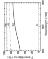
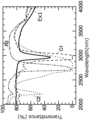
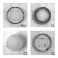
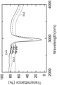
- FIG. 1 is a photograph of a photograph of a sample obtained by the method for producing silicon oxynitride glass of the present invention. Transmission spectrum by UV-Visible spectrophotometer. It is a transmission spectrum with a Fourier transform infrared spectrophotometer.
- the embodiment shown below is an example embodying the technical idea of the present invention. It is not specific to Also, the drawings are schematic. Therefore, the relationship, ratio, etc. between the thickness and the planar dimension may differ from the actual one, and the relationship and ratio of the dimension may differ between drawings.
- sica glass means glass having a three-dimensional network structure in which oxygen atoms at the vertices of silicon dioxide (SiO 4 ) tetrahedrons are shared, and pure silica glass containing substantially no dopants is preferred. .
- silicon oxynitride glass means silica glass in which some of the oxygen (O) atoms in the silica glass are replaced with nitrogen atoms (N), and typically constitutes silicon oxynitride glass.
- the nitrogen content is 0.01 to 99% by mass. 1 to 90% by mass is preferable, 2 to 80% by mass is more preferable, and 3 to 50% by mass is even more preferable.
- Silicon oxynitride glass does not contain silicon nitride (Si 3 N 4 ). Also, the nitrogen content is measured by the method described in the examples below.
- silicon oxynitride glass means a bulk body with a relative density (bulk density/true density) of 90% or more, more preferably 95% or more. Further, the silicon oxynitride glass preferably has a light transmittance of 20% or more at a thickness of 1.94 mm in a wavelength range of 400 to 700 nm.
- a method for producing a silicon oxynitride glass according to an embodiment of the present invention comprises contacting silica particles with ammonia gas under heating, and particles obtained by the contact and sintering by heating above 1500° C. by a spark plasma sintering method.
- FIG. 1 is a flow chart showing the procedure of this manufacturing method.
- step S10 silica (SiO 2 ) particles and ammonia gas (NH 3 ) are brought into contact under heating (nitriding step). Through this nitriding step, some of the oxygen atoms in the silica are replaced with nitrogen atoms to obtain silicon oxynitride particles (silicon oxynitride particles).
- nitrided silica airgel having a large surface area is suitable as a raw material for silicon oxynitride glass (bulk body).
- a material obtained by bringing silica airgel into contact with ammonia gas under heating and nitriding it as a raw material for producing silicon oxynitride glass.
- a transparent silicon oxynitride glass (bulk body) with high relative density should be obtained.
- silicon oxynitride glass with a high nitrogen content could not be produced. Or, even if they could be produced, they were particles or microscopic solids, and bulk bodies that could be applied to optical members and the like could not be produced.
- the silica particles (silicon dioxide particles) used in the nitriding step of step S10 are not particularly limited, and known silica particles can be used. Specific examples include particles of natural silica, synthetic silica, silica balloons, mesoporous silica, silica gel, and quartz. Among them, amorphous silica particles are preferable from the viewpoint of obtaining a silicon oxynitride glass having better optical properties and mechanical properties.
- Silica particles are those produced from natural silica, those synthesized by the sol-gel method and/or hydrolysis of chlorosilane, and from these by metal removal purification to remove aluminum, sodium, iron, etc. A material with reduced impurities or the like can be used.
- the content of impurities in silica particles is not particularly limited.
- the content is preferably 0.1 to 50 ppm by mass, and 0.1 to 10 ppm by mass. more preferred.
- the aluminum content is 50 mass ppm or less, crystal formation during sintering is further suppressed, and when it is 0.1 mass ppm or more, the cost effectiveness is excellent, but the silica particles substantially contain aluminum. It is preferable that there is no content (the content is below the detection limit).
- the content is preferably 0.01 to 1 ppm by mass, more preferably 0.05 to 1 ppm by mass.
- the sodium content is 1 ppm by mass or less, the obtained silicon oxynitride glass tends to have a more excellent light transmittance, and when it is 0.01 mass ppm or more, it is more cost-effective, but the silica particles is substantially free of sodium.
- the content is preferably 0.1 to 5 ppm by mass, more preferably 0.1 to 2 ppm by mass.
- the iron content is 5 ppm by mass or less, the resulting silicon oxynitride glass tends to have better light transmittance, and when it is 0.1 mass ppm or more, it is more cost effective. is preferably substantially free of iron.
- the average diameter (average particle diameter) of the primary particles of the silica particles is not particularly limited, but from the viewpoint that nitridation tends to progress more efficiently, and the obtained silicon oxynitride glass has better optical properties and / or From the viewpoint of easily having better mechanical properties, it is preferably 1000 nm or less, more preferably 100 nm or less, even more preferably 50 nm or less, and although the lower limit is not particularly limited, it is generally preferably 3 nm or more.
- step S10 the silica particles and ammonia gas are brought into contact with each other under heating, so that nitrogen atoms are taken into the network structure of silica and nitridation occurs. It is speculated that the silanol and/or siloxane moieties interact with ammonia to form amines when ammonia gas contacts silica at elevated temperatures.
- the heating temperature during nitriding is not particularly limited, but the maximum temperature (reaching temperature) is preferably 600°C or higher, more preferably 800°C or higher, and even more preferably 900°C or higher.
- the upper limit is preferably 1200° C. or lower, more preferably 1100° C. or lower.
- the method of bringing the silica particles into contact with the ammonia gas is not particularly limited, but as one form, a method of heating the silica particles placed still in a tubular furnace and circulating a predetermined amount of ammonia gas through the tubular furnace. mentioned.
- the flow rate of the ammonia gas at this time is not particularly limited, but for example, when using a tubular furnace with a furnace interior of 65 mm ⁇ 300 L and a furnace core tube of 60 mm ⁇ , it is preferably 10 to 1000 mL/min, and 200 to 700 mL/min. It is preferable to
- the rate of temperature increase up to the maximum temperature is not particularly limited, but is preferably 1 to 20° C./min, more preferably 2 to 10° C./min.
- the holding time at the maximum temperature is not particularly limited, but as one form, 0.5 to 24 hours is preferable, and 1 to 18 hours is more preferable.
- the silica particles are nitrided by the above-described nitriding step.
- the content of nitrogen atoms contained in the nitrided silica particles (silicon oxynitride particles) (when using a mixture of particles, the average value considering the composition) is not particularly limited, but the obtained silicon oxynitride glass From the viewpoint of having better optical properties, better thermal properties, and/or better mechanical properties, when the mass of the whole particles is 100% by mass, it is preferably 5% by mass or more, and 10% by mass or more. is more preferable, and 15% by mass or more is even more preferable.
- the upper limit is not particularly limited, it is generally preferably 50% by mass or less, more preferably 40% by mass or less.
- the content of nitrogen atoms contained in the silicon oxynitride particles means the content of nitrogen atoms measured by the method described in Examples below.
- the mass-based content ratio (N/Si) of the nitrogen atom content to the silicon atom content in the silicon oxynitride particles is not particularly limited, but the obtained silicon oxynitride glass has better optical properties, and From the viewpoint of easily having better mechanical properties, it is preferably 0.10 or more, more preferably 0.20 or more, and even more preferably 0.27 or more. Although the upper limit is not particularly limited, it is preferably 0.50 or less as one form.
- the atomic ratio of nitrogen atoms to silicon atoms (N/Si) in the silicon oxynitride particles is not particularly limited, the obtained silicon oxynitride glass has better optical properties and better mechanical properties. 0.7 or more is preferable, and 0.8 or more is more preferable from the viewpoint of ease of operation. Although the upper limit is not particularly limited, as one form, 1.2 or less is preferable, and 1.0 or less is more preferable.
- step S11 a green compact of the silicon oxynitride particles obtained in step S10 is prepared, and then in step S12, this green compact is subjected to spark plasma sintering (SPS: Spark Plasma Sintering).
- SPS Spark Plasma Sintering
- Step S11 and step S12 may be performed sequentially or simultaneously.
- step S10 in addition to the silicon oxynitride particles, silica particles and/or silicon oxynitride particles having different nitrogen contents may be mixed to form the powder compact. By adding other particles, the nitrogen content in the raw material powder (green compact) can be more easily adjusted.
- FIG. 2 is a schematic diagram of the SPS device.
- the sample 20 is filled in a high-strength carbon mold consisting of a cylindrical graphite die 13 with a carbon sheet 14 wound on its inner peripheral surface and graphite punches 12 fitted in upper and lower openings.
- Each of the graphite punches 12 is connected to a pair of electrodes 11 connected to a DC power supply 15, and pulse-energized.
- Compressive stress symbol “P” is applied to the graphite punch 12 from above and below, and the reaction takes place within the chamber 16 .
- the pressing force is not particularly limited, it is preferably 1 to 100 MPa as one form.
- the lower limit is more preferably 50 MPa or higher, even more preferably 70 MPa or higher.
- the upper limit is preferably 90 MPa or less.
- the chamber 16 is preferably filled with an inert gas, and more preferably filled with nitrogen gas.
- the sintering temperature (maximum temperature, holding temperature) is above 1500°C. If the sintering temperature is 1500° C. or less, the sintering does not proceed sufficiently and a transparent silicon oxynitride glass cannot be obtained. In this respect, the sintering temperature is preferably 1550°C or higher, more preferably higher than 1550°C. On the other hand, the upper limit is not particularly limited, but if it is 2000° C. or less, it is more cost-effective. In this respect, 1800° C. or lower is more preferable, and 1700° C. or lower is even more preferable. Also, the temperature raising program is not particularly limited.
- the heating rate from the predetermined temperature to the holding temperature is preferable to adjust the heating rate from the predetermined temperature to the holding temperature to about 5 to 150° C./min.
- the temperature may be raised at a constant temperature from room temperature to the holding temperature, or may be raised stepwise.
- Other processing conditions may be appropriately determined with reference to known documents, for example, Japanese Patent Application Laid-Open No. 11-11961.
- the silicon oxynitride glass obtained by the above method has excellent optical properties, excellent mechanical properties, and excellent thermal properties. Available.
- a silicon oxynitride glass according to an embodiment of the present invention is a silicon oxynitride glass (hereinafter also referred to as "the present silicon oxynitride glass") that can be produced by the method for producing a silicon oxynitride glass described above.
- the present silicon oxynitride glass contains 12.0% by mass or more of nitrogen atoms.
- a method for producing silicon oxynitride glass a method of nitriding an airgel obtained by a sol-gel method and densifying it has been adopted, as described in Non-Patent Document 1. This is because the large surface area of airgel promotes efficient nitridation, which is believed to be advantageous in the production of silicon oxynitride glass.
- the inventors of the present invention conceived of a simple and efficient nitriding treatment by making the raw material into powder (particles) and nitriding in the powder state, Furthermore, by adopting SPS that can be pressure-sintered in a nitrogen atmosphere (even if not in a vacuum), we have succeeded in manufacturing silicon oxynitride glass in an incomparably simple manner.
- the nitrogen content can be easily adjusted (increased) by a nitriding method different from the conventional method, and it has characteristic properties as a silicon oxynitride glass obtained by a nitriding/sintering method different from the conventional method. I know that.
- the present silicon oxynitride glass has a light transmittance of 65% or more at a thickness of 1.94 mm (converted) in the wavelength range of 2000 to 2500 nm.
- the light transmittance in this specification means that the light transmittance is equal to or higher than a certain value over the entire predetermined wavelength range. That is, it means that the light transmittance is 65% or more over the entire wavelength range of 2000 to 2500 nm.
- the light transmittance is a value measured by the method described in Examples. In the evaluation of the light transmittance, when a sample having a thickness different from 1.94 mm is used, a value obtained by converting the measured value (transmittance) at the thickness to the thickness of 1.94 mm is used.
- silica glass is known to have different OH group contents and the like depending on the manufacturing method, and to have large differences in various physical properties, particularly optical properties. Therefore, it is unlikely that the characteristic optical properties as described above were obtained in the silicon oxynitride glass obtained by the conventional method (the optical properties cannot be evaluated), and the silicon oxynitride glass obtained by the present production method. can be considered to have been achieved for the first time by
- the light transmittance in the above wavelength range is preferably 70% or higher, more preferably 75% or higher, and even more preferably 80% or higher. Although the upper limit is not particularly limited, generally 100% or less is preferable.
- the present silicon oxynitride glass has a light transmittance of 65% or more in the wavelength range of 2875 nm or less from 2500 nm to 2875 nm.
- the light transmittance in the above range is 65% or more, the transmittance of near-infrared light becomes more sufficient, and it is more suitable for use as an optical waveguide for propagating infrared light and as a window material/optical member.
- 68% or more is preferable, 70% or more is more preferable, and 75% or more is even more preferable.
- the upper limit is not particularly limited, it is preferably 100% or less as one form.
- the nitrogen content in the present silicon oxynitride glass is 12.0% by mass or more, preferably 13.0% by mass or more, and more preferably 13.5% by mass or more.
- the nitrogen content in the silicon oxynitride glass is 12.0% by mass or more, the light transmittance in the wavelength region of 2 ⁇ m (2000 nm) or more tends to be higher.
- the nitrogen content is 13.0% by mass or more, more preferably 13.5% by mass or more, a silicon oxynitride glass having better mechanical properties (particularly rigidity) can be obtained.
- the upper limit of the nitrogen content is not particularly limited, but as one form, if it is 50.0% by mass or less, it is excellent in terms of cost effectiveness in relation to the light transmittance at wavelengths of 2 ⁇ m (2000 nm) or longer. In this regard, 20.0% by mass or less is preferable, and 15.0% by mass or less is more preferable.
- silicon oxynitride glass (particles) or nitrogen in a powder compact The atom content is preferably 13.0% by mass or more, and preferably 20.0% by mass or less.
- the reference content ratio (N/Si) of the nitrogen atom content to the silicon atom content in the present silicon oxynitride glass is not particularly limited, but it is It is preferably 0.27 or more, more preferably 0.28 or more, and even more preferably 0.29 or more, in terms of obtaining silicon oxynitride glass having properties.
- the upper limit is not particularly limited, as one form, it is preferably 0.50 or less, more preferably 0.40 or less, and even more preferably 0.35 or less.
- the atomic ratio (N/Si) of nitrogen atoms to silicon atoms in the present silicon oxynitride glass is not particularly limited, a silicon oxynitride glass having better optical properties, thermal properties and/or mechanical properties can be obtained. is preferably 0.6 or more, and preferably 1.0 or less.
- the light transmittance of the present silicon oxynitride glass at a wavelength of 400 to 700 nm (hereinafter also referred to as “visible light region”) at a thickness of 1.94 mm is not particularly limited, but is preferably 50% or more.
- the present silicon oxynitride glass is more suitable for use as a window material or the like.
- the light transmittance in the visible light region is preferably 53% or more.
- the upper limit is not particularly limited, it is preferably 100% or less as one form.
- the light transmittance of the present silicon oxynitride glass in the visible light region means a value measured by the method described in Examples described later, and the definition of the light transmittance is as described above.
- the refractive index of the present silicon oxynitride glass in the visible light region is preferably 1.60 or more.
- a refractive index of 1.60 or more in the above wavelength range is more suitable for use as an optical member or the like.
- the refractive index in the visible light region is more preferably 1.62 or higher.
- the upper limit is not particularly limited, it is preferably 1.80 or less as one form.
- the thermal conductivity of the present silicon oxynitride glass is preferably 2.00 W/(m K) or more, more preferably 2.20 W/(m K) or more, and further preferably 2.40 W/(m K) or more. 2.60 W/(m ⁇ K) or more is particularly preferable.
- the upper limit is not particularly limited, as one form, it is preferably 15.00 W / (m K) or less, more preferably 10.00 W / (m K) or less, and further 5.00 W / (m K) or less. 4.00 W/(m ⁇ K) or less is particularly preferable.
- the thermal conductivity in this specification means the value measured by the method described in the example mentioned later.
- the specific heat of the present silicon oxynitride glass is preferably 0.800 J/(g ⁇ K) or more, more preferably 0.900 J/(g ⁇ K) or more.
- the upper limit is not particularly limited, as one form, 2.200 J/(g ⁇ K) or less is preferable. It should be noted that the specific heat in this specification means a value measured by the method described in Examples described later.
- the thermal diffusivity of the present silicon oxynitride glass is preferably 0.90 mm 2 /s or more.
- the upper limit is not particularly limited, as one form, it is preferably 6.00 mm 2 /s or less, more preferably 3.00 mm 2 /s or less, and even more preferably 2.00 mm 2 /s or less.
- the thermal diffusivity in this specification means a value measured by a method described in Examples described later.
- the Young's modulus of the present silicon oxynitride glass is preferably 100 GPa or more.
- the Young's modulus is more preferably 120 GPa or more, more preferably 130 GPa or more, particularly preferably 140 GPa or more, and most preferably 145 GPa or more.
- the upper limit is not particularly limited, as one form, it is preferably 300 GPa or less, more preferably 200 GPa or less.
- Young's modulus in this specification means a value measured by a method described in Examples described later.
- the Vickers hardness of the present silicon oxynitride glass is preferably 10.0 GPa or more.
- the Vickers hardness is preferably 11.0 GPa or higher, more preferably 12.0 GPa or higher, and even more preferably 15.0 GPa or higher.
- the upper limit is not particularly limited, it is preferably 20.0 GPa or less as one form.
- Vickers hardness in this specification means the value measured by the method described in the Example mentioned later.
- the rigidity of the silicon oxynitride glass is preferably 40 GPa or more.
- the modulus of rigidity is more preferably 50 GPa or more, still more preferably 55 GPa or more, and particularly preferably 60 GPa or more.
- the upper limit is not particularly limited, it is preferably 100 GPa or less as one form.
- the modulus of rigidity in this specification means a value measured by a method described in Examples described later.
- the Poisson's ratio of the present silicon oxynitride glass is preferably 0.180 or higher, more preferably 0.190 or higher, even more preferably 0.200 or higher, and particularly preferably 0.210 or higher. Although the upper limit is not particularly limited, it is preferably 0.250 or less as one form.
- the Poisson's ratio in the present specification means a value measured by the method described in Examples below.
- the glass transition temperature of the present silicon oxynitride glass is preferably 1200°C or higher, more preferably 1300°C or higher.
- a glass transition temperature herein means a glass transition temperature measured by differential thermal analysis.
- the shape and size of the present silicon oxynitride glass are not particularly limited, and may be appropriately determined according to the application. 0.5 cm ⁇ 0.5 cm or more is preferred.
- the new silicon oxynitride glass produced by a new method that has not been studied conventionally has better heat resistance, better optical properties, and better optical properties than silica glass. It has mechanical properties.
- the light transmittance at a thickness of 1.94 mm in the wavelength region of 2000 to 2500 nm is 65% or more, and it is more suitable for use as an optical waveguide for propagating infrared light, an optical member, and the like.
- the silicon oxynitride glass of the present invention has an infrared light transmittance equal to or higher than that of silica glass, and is produced by a simpler method. It is possible.
- the silicon oxynitride glass of the present invention can be preferably used as optical waveguides, infrared image furnaces, window materials, and optical members, which will be described later.
- An optical waveguide according to an embodiment of the present invention (hereinafter also referred to as "the present optical waveguide") is an optical waveguide that contains the silicon oxynitride glass and propagates infrared light.
- FIG. 3 is an explanatory diagram of this optical waveguide.
- the optical waveguide 30 has a cylindrical core 31 made of silicon oxynitride glass and a clad 32 arranged to cover the outer periphery of the core 31, and can be used to propagate infrared rays in the vertical direction of the drawing.
- the optical waveguide 30 uses silicon oxynitride glass having excellent light transmittance in the wavelength region of 2 ⁇ m or more as the core 31, even if the optical waveguide 30 is fiber-shaped and long, the transmission loss can be made smaller.
- the optical waveguide 30 has the clad 32
- the optical waveguide according to the embodiment of the present invention may not have the clad 32.
- Silicon oxynitride glass has a high refractive index as described above, and tends to have a smaller transmission loss.
- the optical waveguide 30 may further have a protective coating on the outer peripheral side of the clad 32 .
- the outer diameter of the core is not particularly limited, and may be appropriately adjusted according to the application, but as one form, it may be 1 ⁇ m to 2 mm.
- the thickness of the clad is not particularly limited, but may be 20 ⁇ m to 2 m, or 20 to 200 ⁇ m, as one form.
- the material of the clad is not particularly limited, but silica glass can be mentioned as one form.
- the optical waveguide 30 is fiber-shaped, the shape of the optical waveguide according to the embodiment of the present invention is not limited to the above, and can be changed as appropriate.
- it may be in the form of a flat plate having a clad layer on the substrate and a core 31 containing silicon oxynitride glass.
- the core (layer) contains the silicon oxynitride glass described above.
- the silicon oxynitride glass described above has a high transmittance of light in a region of 2 ⁇ m or more and a high refractive index, so that the transmission loss tends to be smaller.
- the infrared image furnace of the present invention (hereinafter also referred to as “the present infrared image furnace”) includes the optical waveguide.
- FIG. 4 is an explanatory diagram of an infrared image furnace according to an embodiment of the present invention.
- the infrared image furnace 40 includes a pair of opposing 1/2 ellipsoidal mirrors 42 and 43, an infrared light source 44 arranged at the focal position of one 1/2 ellipsoidal mirror 42, and the other 1/2 elliptical mirror. and an optical waveguide 30 arranged at the focal position of the body mirror 43 .
- Infrared light 45 emitted from an infrared light source 44 is reflected and condensed by the reflecting surfaces 41 of the two 1/2 ellipsoidal mirrors 42 and 43, and an optical waveguide arranged at the focal position of the 1/2 ellipsoidal mirror 43. 30 , propagates through the optical waveguide 30 , emerges from the other end (condensed infrared light 46 in the drawing), and irradiates an object 47 .
- This infrared image furnace (infrared heating device) has an optical waveguide 30 incorporated for the propagation of infrared rays, so it has lower transmission loss and excellent efficiency.
- the silicon oxynitride glass of the present invention has excellent heat resistance, so even if the temperature of the object becomes higher, damage to the optical waveguide 30 is more likely to be suppressed. It has excellent characteristics as a heating device incorporated in an experimental device or the like that requires heating to a higher temperature and/or heating of a narrow area.
- a temperature distribution measuring device of the present invention includes the above optical waveguide.
- FIG. 5 is an explanatory diagram of the temperature distribution measuring device of the present invention.
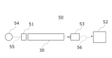
- the temperature distribution measuring device 50 has an objective lens 51 , an optical waveguide 30 , an infrared camera 53 and a display device 52 .
- a temperature distribution measuring device 50 collects infrared light 55 emitted from an object 54 by an objective lens 51 and receives it by an infrared camera 53 via an optical waveguide 30 .
- the obtained signal is wirelessly transmitted 56 (or wired) to a display device 52 and displayed as a temperature distribution.
- This temperature distribution measuring device uses the optical waveguide 30 described above for the propagation of infrared rays. Since the optical waveguide 30 described above has superior heat resistance, it has an excellent characteristic that it can be applied even when the temperature of the object to be measured is high. In addition, since the light transmittance is high in the wavelength region of 2 ⁇ m or more, the transmission loss is less and more accurate measurement is possible.
- a radiation thermometer of the present invention includes the optical waveguide.
- FIG. 6 is an explanatory diagram of the radiation thermometer of the present invention.
- the radiation thermometer 60 has an optical waveguide 30 with antireflection coatings 63 applied to both ends, a bandpass filter 61 and an infrared sensor 62 .
- Infrared light 65 emitted from the object 64 enters the optical waveguide 30 from one end through the antireflection coat 63 and exits from the other end through the antireflection coat 63 .
- the emitted light enters the infrared sensor 62 via the bandpass filter 61 .
- the optical waveguide 30 has an excellent refractive index and an excellent light transmittance in the wavelength region of 2 ⁇ m or longer, the transmission loss is smaller and more accurate temperature measurement is possible.
- the silicon oxynitride glass according to the embodiment of the present invention has excellent heat resistance, excellent refractive index, and excellent light transmittance in the region of wavelengths of 2 ⁇ m or more, and is therefore incorporated into optical devices. It can be used as an optical member. In addition, since it has excellent light transmittance even in the visible light region, it can be used as a window material for monitoring the inside of a high-temperature heating furnace, etc., which could not be realized with conventional silica glass.
- Silicon oxynitride particles were prepared in the same manner as in Synthesis Example 1 except that spherical fused silica (“FB-15D”, manufactured by Denka, specific surface area 1.3 m 2 /g, particle diameter (d50) 15 ⁇ m) was used as the raw material. was synthesized.
- FB-15D spherical fused silica
- the sample sintered by the SPS method was polished on both sides with #220 to #2000 polishing paper (Refinetech), then 6 ⁇ m diamond slurry (41-606, Refinetech) and a polishing buff (56 -208, Refinetech).
- the holding temperature (maximum temperature) during sintering is 1600 ° C.
- Example 1 symbol “Ex1”
- Comparative Example 1 symbol “C1”
- Comparative Example 3 symbol “C3”
- Comparative Example 2 a product obtained by sintering silica particles was designated as Comparative Example 2 (symbol “C2”).
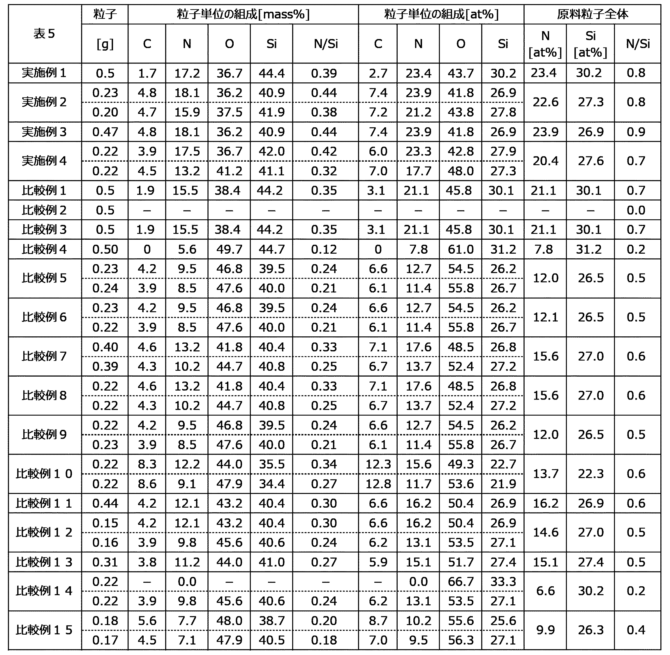
- Silicon oxynitride glass was produced in the same manner as in Synthesis Example 1 using two types of silicon oxynitride particles synthesized based on "AEROSIL-300". As raw material particles, two types of silicon oxynitride particles were mixed and used. The mixing ratio of the two types of silicon oxynitride glasses was adjusted so that the atomic ratio of N/Si of the raw material particles as a whole was the value shown in Table 5. The composition of each particle and the mixing ratio are shown in Table 5.
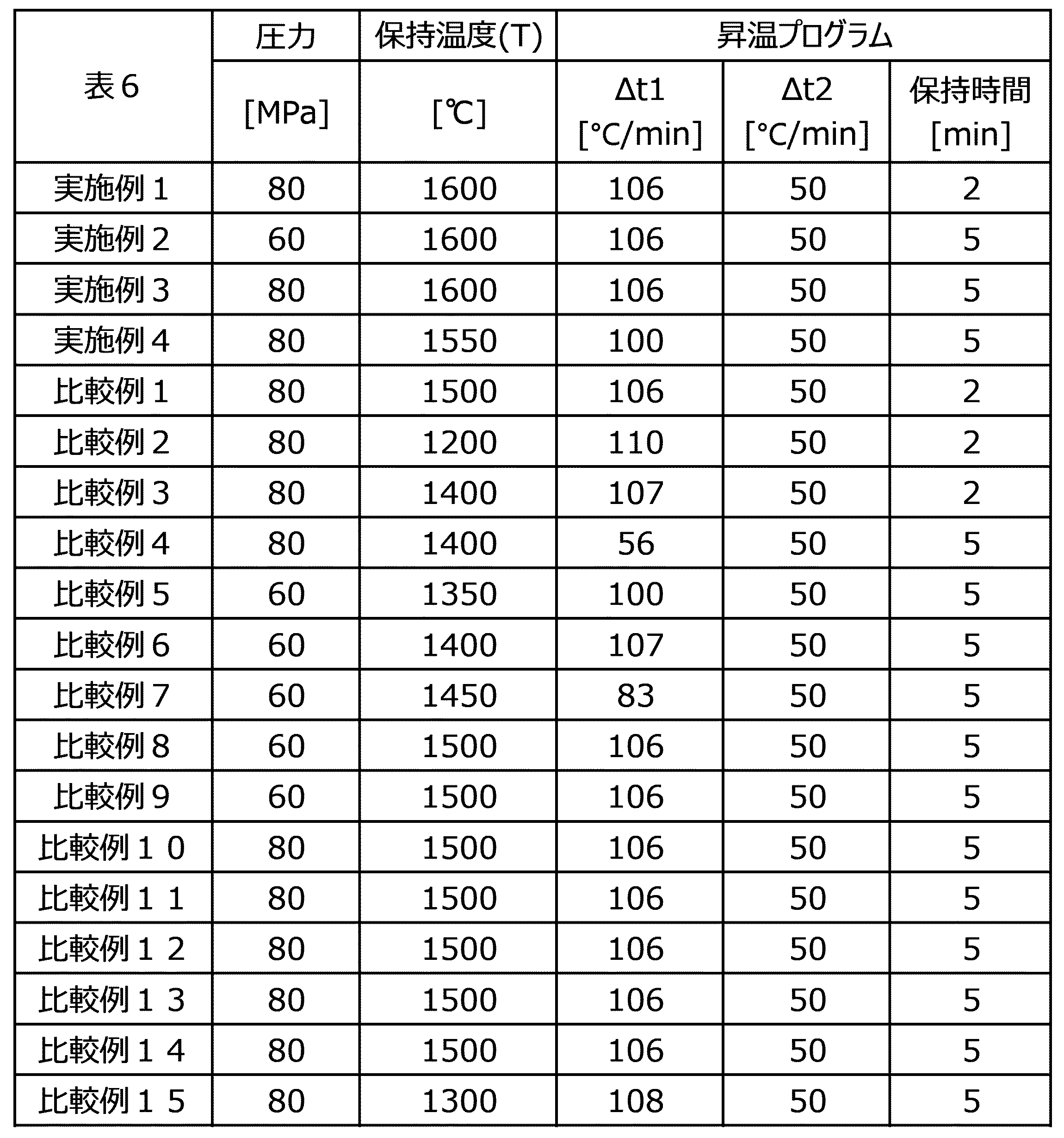
- Silicon oxynitride glass was produced in the same manner as in Example 1 except that the SPS conditions (pressure, holding temperature, and temperature rise program) for the obtained raw material particles were adjusted as shown in Table 6.
- SPS conditions pressure, holding temperature, and temperature rise program
- Table 5 the examples and comparative examples written in two columns indicate that the green compacts were produced by mixing the particles shown in the upper and lower columns.
- Example 3 Comparative Examples 11 and 13
- the silicon oxynitride particles listed in Table 5 (both of which were synthesized in the same manner as in Synthesis Example 1 based on "AEROSIL-300") were used as raw materials, and the SPS conditions were as listed in Table 6.
- Each silicon oxynitride glass was produced in the same manner as in Example 1, except that
- Example 4 A silicon oxynitride glass was produced in the same manner as in Example 1, except that "Aeroperl (Nippon Aerosil)" was used instead of “AEROSIL-300” and the SPS conditions were as described in Table 6. . In the table below, “-" indicates no measurement data.
- the bulk density of the samples was calculated from the mass, diameter and thickness of each sample.
- a dry density meter (“Accupic II 1345” manufactured by Shimadzu Corporation) equipped with He (helium) gas was used to measure the density of a sample of about 0.4 g, and this value was taken as the true density.
- composition analysis A composition analysis was performed using a wavelength dispersive X-ray fluorescence spectrometer (“WDXRF”) (“ZSX PrimusII”, manufactured by Rigaku Corporation). The composition of the raw material particles was measured by molding 0.6 g of the nitrided particles into pellets with a diameter of 12 mm by uniaxial pressing at 10 MPa/5 min, fixing them in a holder with an inner diameter of 10 mm.
- WDXRF wavelength dispersive X-ray fluorescence spectrometer
- Table 2 shows the results of density measurement and composition analysis of Example 1 and Comparative Examples 1, 2, and 3. Moreover, FIG. 10 is a photograph of the obtained sample, and one side of each grid is 5 mm. The results of density measurement and composition analysis of other examples and comparative examples will be described later.
- Example 1 As shown in FIG. 10, in Example 1 (“Ex1”, sintering temperature: 1600° C.) and Comparative Example 2 (“C2”, silica particles sintered at 1200° C.), transparent samples (bulk body) was obtained. On the other hand, in Comparative Example 1 (C1, sintering temperature: 1500° C.) and Comparative Example 3 (C3, sintering temperature: 1400° C.), transparent samples were not obtained. Similarly, in Examples 2 to 4, transparent silicon oxynitride glass (bulk body) was obtained. On the other hand, in Comparative Examples 1 to 15, no transparent silicon oxynitride glass (bulk body) was obtained.
- Example 1 the samples of Example 1, Comparative Example 1, and Comparative Example 3 contained a certain amount of nitrogen (N) in the composition derived from the raw material powder. In Example 1, it was 19.0 atomic percent (at %). On the other hand, no nitrogen was detected in the sample of Comparative Example 2.
- Example 1 and Comparative Example 2 had relative densities of 90% or more, and uniform bulk bodies were obtained. . "-" in the table indicates no data or no measurement.
- Light transmittance measurement Light transmittance was measured using an ultraviolet-visible spectrophotometer ("SolidSpec-3700", manufactured by Shimadzu Corporation) and a Fourier transform infrared (FT-IR) spectrophotometer ("SpectrumGX 2000R", manufactured by Perkin-Elmer). It was measured. A mask with a diameter of 6 mm was used for the measurement.
- the measurement parameters of the UV-Vis spectrophotometer are as follows. The measured values were corrected with the thickness of each sample being 1.94 mm. The thickness of each sample used is listed in Table 8.
- the measurement parameters of the Fourier transform infrared (FT-IR) spectrophotometer are as follows.
- FIG. 7 is the transmission spectrum by the UV-visible spectrophotometer
- FIG. 8 is the transmission spectrum by the FT-IR spectrophotometer. Each spectrum is before correction of thickness, and the thickness of each sample is described in Table 8.
- R3 is the measurement result of commercially available silica glass (synthetic silica glass "Viosil-SQ" manufactured by Shin-Etsu Chemical, not silicon oxynitride glass, thickness 2.00 mm). From the results of FIG. 3, the sample of Example 1 (Ex1, sintering temperature 1600 ° C.) has a transmittance of light in the wavelength range of 400 to 700 nm (converted to a thickness of 1.94 mm) of 50% or more (53% or more). It turns out there is.
- Example 1 had a light transmittance (converted to a thickness of 1.94 mm) of 80% or more in the wavelength range of 2000 to 2500 nm.
- Comparative Example 1 (“C1”, sintering temperature: 1500 ° C.) and Comparative Example 2 (“C2”, silica particles sintered at 1200 ° C.) have hydroxyl groups in the molecules.
- There is an absorption peak derived from and in Comparative Example 1 (“C1”), the transmittance (converted to a thickness of 1.94 mm) is about 70%, and in Comparative Example 2 (“C2”), the transmittance is 40%. %.
- Example 1 had a transmittance of 75% or more for light in the region of 2875 nm (converted to a thickness of 1.94 mm) over a wavelength of 2500 nm.
- Comparative Example 1 (“C1”, sintering temperature: 1500° C.) and Comparative Example 2 (“C2”, sintered silica particles) are derived from hydroxyl groups in the molecules. An absorption peak was present, and the sample of Comparative Example 1 (C1) had a region where the transmittance was less than 70%, and the sample of Comparative Example 2 had a region of almost no transmission. It was also found that Example 1 had a better transmittance than R3 (commercially available silica glass).
- the sample of Example 1 has a high transmittance in a wide wavelength range of 2000 to 2850 nm, and can be obtained by a simple method that is different from the conventional method of reducing hydroxyl groups for silica glass. , it was found that transparency to light in this region can be ensured.
- a spectroscopic ellipsometer (“M-2000U” manufactured by JA Woollam) was used to measure the refractive index.
- the incident angle ranged from 50 to 80 degrees, and the wavelength range of 250 to 1000 nm was measured every 10 degrees.
- the number of accumulation times was 40, and the incident light polarization angle was 45°.
- FIG. 9 is a diagram showing the measurement results of the refractive index.
- the spectrum is before correction for thickness, and the thickness of each sample is listed in Table 8. From the results of FIG. 9, it was found that the sample of Example 1 (“Ex1”, sintering temperature: 1600° C.) had a refractive index of 1.63 or more in the wavelength range of 400 to 700 nm.
- the sample of Comparative Example 2 (C2) is about 1.50 to 1.60, and the commercially available silica glass "R3" (thickness: 2.00 mm) is about 1.44 to 1.51. I found out. It was found that the sample of Example 1 (“Ex1”) had a high refractive index over a wide wavelength range.
- thermo diffusivity/thermal conductivity measuring device LFA447, manufactured by NETZSCH Japan K.K.
- the sample surface was coated with carbon spray and measured.
- a finite pulse width correction was performed on the obtained temperature rise curve, and the thermal diffusivity ⁇ was calculated using the Cowan model. Pylex was used as a standard sample for the calculation of the specific heat capacity Cp .
- Reference Example 1 is the literature value for silica glass manufactured by Tosoh Corporation ("ES", a synthetic quartz glass obtained by hydrolyzing and melting SiCl 4 with an oxyhydrogen flame). (Table 4 is the same).
- Reference Example 2 is the literature value of Kyocera's Si 3 N 4 (SN-240) (same as in Table 4). Also, the numerical values enclosed in parentheses in the table are calculated values.
- Example 1 has a higher specific heat, a higher thermal diffusivity, and a higher thermal conductivity than the samples of Comparative Example 2 and Reference Example 1. I understand.
- Young's modulus was measured using the ultrasonic pulse method.
- Ultrasonic waves (longitudinal waves and transverse waves) are propagated through a buffer rod adhered to the sample, and the wave round-trip time (longitudinal wave time tl , transverse wave time tt ) is read from the waveform obtained by the oscilloscope, and the sample thickness L
- ⁇ bulk density (kg/m 3 )
- V 1 longitudinal wave velocity (m/s)
- V t transverse wave velocity (m/s).
- the Vickers hardness was measured using a micro Vickers hardness tester (“MVK-VL” manufactured by Akashi Seisakusho). A Vickers indenter was driven into the sample surface. The indentation load was 100 gf, and the load time was 15 sec. After unloading, the diagonal lines of the indentation were measured, and the Vickers hardness was calculated from the average value. The indentation was observed with an optical microscope ("ECLPSE LV100", manufactured by Nikon Solutions Co., Ltd.). Table 4 summarizes the results of the above Young's modulus measurement and Vickers hardness measurement.
- the sample of Example 1 has greater rigidity, Young's modulus, and Vickers hardness than the samples of Comparative Example 2 and Reference Example 1, and is about twice or more. It was found to have excellent mechanical properties.
- Table 7 shows the measurement results of the composition and physical properties of the sintered bodies obtained in each example and comparative example.
- Table 8 shows the measurement results of the light transmittance of the sintered bodies obtained in each example and comparative example.
- FIG. 11 shows transmission spectra of the silicon oxynitride glasses of Examples 2 to 4 obtained by a UV-visible spectrophotometer.
- FIG. 12 shows transmission spectra of the silicon oxynitride glasses of Examples 2 to 4 obtained by a Fourier transform infrared spectrophotometer. In the figure, Examples 2 to 4 are described as "Ex2", “Ex3" and "Ex4", respectively. Some of the results overlap with Tables 2-4.
- the silicon oxynitride glass of Example 1 Compared to the silicon oxynitride glass of Example 2, the silicon oxynitride glass of Example 1, in which the SPS pressing force was set to 70 MPa or more, had a superior light transmittance (2000-2500 nm, over 2500 nm and 2875 nm or less , 400-700 nm).
Landscapes
- Physics & Mathematics (AREA)
- General Physics & Mathematics (AREA)
- Optics & Photonics (AREA)
- Engineering & Computer Science (AREA)
- Chemical & Material Sciences (AREA)
- Manufacturing & Machinery (AREA)
- Materials Engineering (AREA)
- Organic Chemistry (AREA)
- Glass Compositions (AREA)
Abstract
シリカ粒子を加熱下でアンモニアガスと接触させることと、上記接触させることにより得られた酸窒化ケイ素粒子を放電プラズマ焼結法により、1500℃を超える温度に加熱して焼結することと、を含む、酸窒化ケイ素ガラスの製造方法によれば、簡便に酸窒化ケイ素ガラスを製造できる。
Description
本発明は、酸窒化ケイ素ガラスの製造方法、光導波路の製造方法、酸窒化ケイ素ガラス、光導波路、赤外線イメージ炉、窓材、及び、光学部材に関する。
シリカガラスの酸素を窒素に置き換えて得られる、酸窒化ケイ素ガラスが知られている。このような酸窒化ケイ素ガラスの製造方法として、非特許文献1には、テトラエトキシシランの加水分解・重縮合によって得られたエアロゲルを、加熱下でアンモニアガスと接触させて窒化し、窒化処理したエアロゲルを1600℃の真空中で焼結する方法が記載されている。
Journal of Non-Crystalline Solids,2001,vol 286,p.58-63
非特許文献1には、エアロゲルを作成して窒化することと、窒化したエアロゲルを真空下で1600℃まで加熱することが開示されている。しかし、上記の方法では、光学部材に適用できるような(粒子程度の大きさではない)酸窒化ケイ素ガラスの大型のバルク体を製造するのは困難だった。現に、上記文献には、酸窒化ケイ素ガラスの光透過率等については記載されていない。
更に、エアロゲルの作製等のための手順は煩雑で、設備も特殊であり、更に、窒化されたエアロゲルを1600℃まで、真空下で加熱するのは、こちらも設備的な制約が大きい。結果として、上記方法では、酸窒化ケイ素ガラスの産業利用は極めて困難だった。
そこで、本発明は、簡便に酸窒化ケイ素ガラスを製造できる、酸窒化ケイ素ガラスの製造方法を提供することを課題とする。また、本発明は、酸窒化ケイ素ガラス、光導波路、赤外線イメージ炉、窓材、及び、光学部材を提供することも課題とする。
本発明者らは、上記課題を解決すべく鋭意検討した結果、以下の構成により上記課題を解決することができることを見出した。
[1] シリカ粒子を加熱下でアンモニアガスと接触させることと、上記接触させることにより得られた酸窒化ケイ素粒子を放電プラズマ焼結法により、1500℃を超える温度に加熱して焼結することと、を含む、酸窒化ケイ素ガラスの製造方法。
[2] 上記シリカ粒子の1次粒子の平均径が1000nm以下である、[1]に記載の酸窒化ケイ素ガラスの製造方法。
[3] 上記酸窒化ケイ素粒子における、ケイ素原子の含有量に対する窒素原子の含有量の質量基準の含有量比が、0.10以上である、[1]又は[2]に記載の酸窒化ケイ素ガラスの製造方法。
[4] 上記酸窒化ケイ素ガラスは、12.0質量%以上の窒素を含有し、波長2000~2500nmの領域における厚み1.94mmでの光透過率が65%以上である、[1]~[3]のいずれかに記載の酸窒化ケイ素ガラスの製造方法。
[5] [1]~[4]のいずれかに記載の酸窒化ケイ素ガラスの製造方法を含む、赤外光を伝搬する光導波路の製造方法。
[6] 12.0質量%以上の窒素を含有し、波長2000~2500nmの領域における厚み1.94mmでの光透過率が65%以上である、酸窒化ケイ素ガラス。
[7] 波長400~700nmの領域における厚み1.94mmでの光透過率が50%以上である、[6]に記載の酸窒化ケイ素ガラス。
[8] 熱伝導率が2.00W/(m・K)以上である、[6]又は[7]に記載の酸窒化ケイ素ガラス。
[9] 波長2500nmを超えて、2875nm以下の領域における厚み1.94mmでの光透過率が65%以上である、[6]~[8]のいずれかに記載の酸窒化ケイ素ガラス。
[10] 波長400~700nmの領域における屈折率が1.60以上である、[6]~[9]のいずれかに記載の酸窒化ケイ素ガラス。
[11] ケイ素原子の含有量に対する窒素原子の含有量の質量基準の含有量比が、0.27以上である、[6]~[10]のいずれかに記載の酸窒化ケイ素ガラス。
[12] ヤング率が100GPa以上である、[6]~[11]のいずれかに記載の酸窒化ケイ素ガラス。
[13] [6]~[12]のいずれかに記載の酸窒化ケイ素ガラスを含む、赤外光を伝搬する光導波路。
[14] [13]に記載の光導波路を含む、赤外線イメージ炉。
[15] [6]~[12]のいずれかに記載の酸窒化ケイ素ガラスを含む、窓材。
[16] [6]~[12]のいずれかに記載の酸窒化ケイ素ガラスを含む、光学部材。
本発明によれば、簡便に酸窒化ケイ素ガラスを製造できる、酸窒化ケイ素ガラスの製造方法を提供できる。また、本発明によれば、光導波路の製造方法、酸窒化ケイ素ガラス、光導波路、赤外線イメージ炉、窓材、及び、光学部材も提供できる。
以下、本発明について詳細に説明する。
以下に記載する構成要件の説明は、本発明の代表的な実施形態に基づいてなされることがあるが、本発明はそのような実施形態に制限されるものではない。
なお、本明細書において、「~」を用いて表される数値範囲は、「~」の前後に記載される数値を下限値及び上限値として含む範囲を意味する。
以下に記載する構成要件の説明は、本発明の代表的な実施形態に基づいてなされることがあるが、本発明はそのような実施形態に制限されるものではない。
なお、本明細書において、「~」を用いて表される数値範囲は、「~」の前後に記載される数値を下限値及び上限値として含む範囲を意味する。
また、以下に示す実施形態は、本発明の技術的思想を具体化した一例であって、本発明の技術的思想は、構成部品の材質、形状、構造、及び、配置等を下記の実施形態に特定するものではない。また、図面は模式的なものである。そのため、厚みと平面寸法との関係、比率等は現実のものとは異なる場合があり、また、図面相互間においても互いの寸法の関係や比率が異なることがある。
また、特に定義のない限り、本明細書において使用される全ての用語(技術用語、及び、科学用語を含む)は、本開示が属する分野の当業者によって一般的に理解される意味と同じ意味を有する。
本明細書において、「シリカガラス」とは、二酸化ケイ素(SiO4)四面体の頂点の酸素を共有する三次元網目構造を有するガラスを意味し、ドーパントを実質的に含有しない純シリカガラスが好ましい。
本明細書において、酸窒化ケイ素ガラスは、上記シリカガラスにおける酸素(O)原子の一部が窒素原子(N)で置換されたシリカガラスを意味し、典型的には、酸窒化ケイ素ガラスを構成するケイ素(Si)、酸素、窒素、及び、その他の元素(例えば、炭素等の不純物)の質量基準の合計を100質量%としたとき、窒素の含有量が、0.01~99質量%のものを意味し、1~90質量%が好ましく、2~80質量%がより好ましく、3~50質量%が更に好ましい。なお、酸窒化ケイ素ガラスには、窒化ケイ素(Si3N4)は含まれないものとする。また、上記窒素の含有量は、後述する実施例に記載された方法により測定される。
また、酸窒化ケイ素ガラスは、相対密度(かさ密度/真密度)が90%以上のバルク体を意味し、95%以上がより好ましい。また、酸窒化ケイ素ガラスは、波長400~700nmの領域における厚み1.94mmでの光透過率が20%以上であることが好ましい。
[酸窒化ケイ素ガラスの製造方法]
本発明の実施形態に係る酸窒化ケイ素ガラスの製造方法(以下「本製造方法」ともいう。)は、シリカ粒子を加熱下でアンモニアガスと接触させることと、上記接触させることにより得られた粒子を放電プラズマ焼結法により、1500℃を超えて加熱して焼結することと、を含む。
本発明の実施形態に係る酸窒化ケイ素ガラスの製造方法(以下「本製造方法」ともいう。)は、シリカ粒子を加熱下でアンモニアガスと接触させることと、上記接触させることにより得られた粒子を放電プラズマ焼結法により、1500℃を超えて加熱して焼結することと、を含む。
図1は本製造方法の手順を示したフローチャートである。ステップS10において、シリカ(SiO2)粒子とアンモニアガス(NH3)とが加熱下で接触される(窒化工程)。
この窒化工程により、シリカが有する酸素原子の一部が窒素原子により置き換えられ、酸窒化ケイ素の粒子(酸窒化ケイ素粒子)が得られる。
この窒化工程により、シリカが有する酸素原子の一部が窒素原子により置き換えられ、酸窒化ケイ素の粒子(酸窒化ケイ素粒子)が得られる。
従来、酸窒化ケイ素ガラス(バルク体)の製造に用いるための原料としての酸窒化ケイ素は、表面積の大きいシリカエアロゲルを窒化したものが適すると考えられてきた。言い換えれば、シリカエアロゲルに加熱下でアンモニアガスを接触させ窒化して得られたものを、酸窒化ケイ素ガラス製造のための原料とすることが適当だと考えられてきた。
この窒化されたシリカエアロゲルを焼結することで、相対密度が高く、透明な酸窒化ケイ素ガラス(バルク体)が得られるはずだと考えられてきた。
この窒化されたシリカエアロゲルを焼結することで、相対密度が高く、透明な酸窒化ケイ素ガラス(バルク体)が得られるはずだと考えられてきた。
しかし、非特許文献1に記載されたような従来の方法では、窒素の高い(例えば、窒素を12質量%以上含有するような)酸窒化ケイ素ガラスは製造できなかった。又は、製造できたとしても、それは粒子、又は、極微小な固体であり、光学部材等に応用できるようなバルク体は製造できなかった。
しかし、本発明者らは、上記技術常識にとらわれず、シリカエアロゲルを介さずに、透明で品質の高い酸窒化ケイ素ガラスを製造する方法を鋭意検討してきた。エアロゲルを介して酸窒化ケイ素ガラスを製造する方法は、製造装置、コスト面で極めて制約が大きく、大型のバルク体を製造するのが困難で、産業応用上問題があると考えたからである。
本発明者らは、鋭意の検討の結果、シリカ粒子を窒化し、それを圧粉体として放電プラズマ焼結(SPS)することで、より簡便に高品質の酸窒化ケイ素ガラスを製造できることをついに知見し、本発明を完成させた。本製造方法は、粒子(粉体)状態でシリカの窒化を行ったうえで、所定の温度条件のもとでSPSを行う点に特徴点のひとつがある。以下では、各工程において使用される材料、及び、手順等について詳述する。
図1に戻り、ステップS10の窒化工程において使用されるシリカ粒子(二酸化ケイ素粒子)としては特に制限されず、公知のシリカ粒子が使用可能である。
具体的には、天然シリカ、合成シリカ、シリカバルーン、メソポーラスシリカ、シリカゲル、及び、石英等の粒子が挙げられる。なかでも、より優れた光学特性、及び、機械特性を有する酸窒化ケイ素ガラスが得られる観点で、非晶質(アモルファス)シリカ粒子であることが好ましい。
具体的には、天然シリカ、合成シリカ、シリカバルーン、メソポーラスシリカ、シリカゲル、及び、石英等の粒子が挙げられる。なかでも、より優れた光学特性、及び、機械特性を有する酸窒化ケイ素ガラスが得られる観点で、非晶質(アモルファス)シリカ粒子であることが好ましい。
シリカ粒子は、天然のシリカから製造されたもの、ゾル-ゲル法、及び/又は、クロロシランの加水分解によって合成されたもの、及び、これらから、金属除去精製によってアルミニウム、ナトリウム、及び、鉄等の不純物を低減させたもの等を用いることができる。
シリカ粒子の不純物の含有量としては特に制限されないが、例えば、アルミニウムであれば、その含有量は一形態として、0.1~50質量ppmであることが好ましく、0.1~10質量ppmがより好ましい。アルミニウムの含有量が50質量ppm以下であると、焼結時の結晶生成がより抑制され、0.1質量ppm以上であると、費用対効果により優れるが、シリカ粒子はアルミニウムを実質的に含まない(含有量が検出限界以下である)ことが好ましい。
ナトリウムであれば、その含有量は一形態として、0.01~1質量ppmが好ましく、0.05~1質量ppmがより好ましい。ナトリウムの含有量が1質量ppm以下であると、得られる酸窒化ケイ素ガラスがより優れた光透過率を有しやすく、0.01質量ppm以上であると、費用対効果により優れるが、シリカ粒子はナトリウムを実質的に含まないことが好ましい。
鉄であれば、その含有量は一形態として0.1~5質量ppmが好ましく、0.1~2質量ppmがより好ましい。鉄の含有量が5質量ppm以下であると、得られる酸窒化ケイ素ガラスはより優れた光透過性を有しやすく、0.1質量ppm以上であると、費用対効果により優れるが、シリカ粒子は実質的に鉄を含まないことが好ましい。
シリカ粒子の1次粒子の平均径(平均粒子径)は、特に制限されないが、窒化がより効率的に進行しやすい観点、及び、得られる酸窒化ケイ素ガラスがより優れた光学特性、及び/又は、より優れた機械特性を有しやすい観点で、1000nm以下が好ましく、100nm以下がより好ましく、50nm以下が更に好ましく、下限は特に制限されないが、一般に3nm以上が好ましい。
ステップS10において、上記シリカ粒子とアンモニアガスとを加熱下で接触させることで、窒素原子がシリカのネットワーク構造中に取り込まれ、窒化が起こるものと推測される。高温でアンモニアガスがシリカと接触することで、シラノール部分、及び/又は、シロキサン部分がアンモニアと相互作用することでアミンが形成されるものと推測される。
窒化の際の加熱温度としては特に制限されないが、最高温度(到達温度)として、600℃以上が好ましく、800℃以上がより好ましく、900℃以上が更に好ましい。上限としては、1200℃以下が好ましく、1100℃以下がより好ましい。
また、シリカ粒子とアンモニアガスとを接触させる方法としては特に制限されないが、一形態として、管状炉中に静置したシリカ粒子を加熱し、上記管状炉に所定量のアンモニアガスを流通させる方法が挙げられる。
この際のアンモニアガスの流量としては特に制限されないが、例えば、炉内が65mmφ×300L、炉心管が60mmφの管状炉を用いる場合、10~1000mL/分とすることが好ましく、200~700mL/分とすることが好ましい。
この際のアンモニアガスの流量としては特に制限されないが、例えば、炉内が65mmφ×300L、炉心管が60mmφの管状炉を用いる場合、10~1000mL/分とすることが好ましく、200~700mL/分とすることが好ましい。
この際、最高温度まで至る昇温速度としては特に制限されないが、一形態として1~20℃/分が好ましく、2~10℃/分がより好ましい。
また最高温度における保持時間としては特に制限されないが、一形態として、0.5~24時間が好ましく、1~18時間がより好ましい。
また最高温度における保持時間としては特に制限されないが、一形態として、0.5~24時間が好ましく、1~18時間がより好ましい。
上記の窒化工程により、シリカ粒子が窒化される。窒化されたシリカ粒子(酸窒化ケイ素粒子)に含まれる窒素原子の含有量(粒子の混合物を使用する場合には、組成を考慮した平均値)としては特に制限されないが、得られる酸窒化ケイ素ガラスがより優れた光学特性、より優れた熱特性、及び/又は、より優れた機械特性を有する観点で、粒子全体の質量を100質量%としたとき、5質量%以上が好ましく、10質量%以上がより好ましく、15質量%以上が更に好ましい。上限は特に制限されないが、一般に50質量%以下が好ましく、40質量%以下がより好ましい。
なお、本明細書において酸窒化ケイ素粒子に含まれる窒素原子の含有量は後述する実施例に記載の方法により測定される窒素原子の含有量を意味する。
なお、本明細書において酸窒化ケイ素粒子に含まれる窒素原子の含有量は後述する実施例に記載の方法により測定される窒素原子の含有量を意味する。
酸窒化ケイ素粒子におけるケイ素原子の含有量に対する窒素原子の含有量の質量基準の含有量比(N/Si)としては特に制限されないが、得られる酸窒化ケイ素ガラスがより優れた光学特性、及び、より優れた機械特性を有しやすい観点では、0.10以上が好ましく、0.20以上がより好ましく、0.27以上が更に好ましい。上限は特に制限されないが、一形態として、0.50以下が好ましい。
また、酸窒化ケイ素粒子における、ケイ素原子に対する窒素原子の原子比(N/Si)としては特に制限されないが、得られる酸窒化ケイ素ガラスがより優れた光学特性、及び、より優れた機械特性を有しやすい観点では、0.7以上が好ましく、0.8以上がより好ましい。上限は特に制限されないが、一形態として、1.2以下が好ましく、1.0以下がより好ましい。
次に、ステップS11において、ステップS10で得られた酸窒化ケイ素粒子の圧粉体を作成し、次いで、ステップS12において、この圧粉体を、1500℃を超える温度で放電プラズマ焼結(SPS:Spark Plasma Sintering)する。このステップS11、及び、ステップS12は順次実施されてもよいし、同時に実施されてもよい。
なお、ステップS10では、酸窒化ケイ素粒子に加えて、シリカ粒子、及び/又は、窒素含有量が異なる酸窒化ケイ素粒子を混合させて圧粉体を形成してもよい。他の粒子を添加することにより、原料粉(圧粉体)における窒素含有量をより容易に調整できる。
なお、ステップS10では、酸窒化ケイ素粒子に加えて、シリカ粒子、及び/又は、窒素含有量が異なる酸窒化ケイ素粒子を混合させて圧粉体を形成してもよい。他の粒子を添加することにより、原料粉(圧粉体)における窒素含有量をより容易に調整できる。
放電プラズマ焼結は、粒子を成形型に充填し、導電性材料で構成された押圧子によって加圧圧縮して圧粉体とし、この圧粉体にパルス状電圧を印加して、所定温度に加熱する方法であり、圧粉体の作製と、焼結とが、順次、又は、同時に行われる。
上記SPSによれば、圧粉体をジュール熱により加熱するとともに、パルス状電気エネルギーによる放電プラズマの高エネルギーによって、効率的に焼結することができる。なお、圧粉体を予め作製してからSPSを実施してもよい。
上記SPSによれば、圧粉体をジュール熱により加熱するとともに、パルス状電気エネルギーによる放電プラズマの高エネルギーによって、効率的に焼結することができる。なお、圧粉体を予め作製してからSPSを実施してもよい。
図2は、SPS装置の模式図である。試料20は、内周面にカーボンシート14が巻き回された円筒状のグラファイトダイ13と上下の開口に嵌め合わされたグラファイトパンチ12とからなる高強度カーボン型に充填される。グラファイトパンチ12はそれぞれ、直流電源15と接続された一対の電極11と接続され、パルス通電される。また、グラファイトパンチ12は上下から圧縮応力(符号「P」)が印加され、反応は、チャンバ16内で行われる。
押圧力としては特に制限されないが、一形態として、1~100MPaが好ましい。下限は、50MPa以上がより好ましく、70MPa以上が更に好ましい。上限は、90MPa以下が好ましい。また、反応時、チャンバ16内は不活性ガスが充填されていることが好ましく、窒素ガスが充填されていることがより好ましい。
焼結温度(最高温度、保持温度)は1500℃を超える温度である。焼結温度が1500℃以下だと、十分に焼結が進まず、透明な酸窒化ケイ素ガラスが得られない。この点では、焼結温度は1550℃以上が好ましく、1550℃を超えることがより好ましい。
一方、上限は特に制限されないが、2000℃以下だと、費用対効果により優れる。この点で、1800℃以下がより好ましく、1700℃以下が更に好ましい。また、昇温プログラムとしては特に制限されない。一形態として、所定温度から、保持温度までの間の昇温速度を、5~150℃/分程度に調整することが好ましい。室温から保持温度まで、一定温度で昇温されてもよいし、段階的に昇温されてもよい。
その他の処理条件は、公知文献等を参照して適宜定めればよく、例えば、特開平11-11961号公報等が参照できる。
一方、上限は特に制限されないが、2000℃以下だと、費用対効果により優れる。この点で、1800℃以下がより好ましく、1700℃以下が更に好ましい。また、昇温プログラムとしては特に制限されない。一形態として、所定温度から、保持温度までの間の昇温速度を、5~150℃/分程度に調整することが好ましい。室温から保持温度まで、一定温度で昇温されてもよいし、段階的に昇温されてもよい。
その他の処理条件は、公知文献等を参照して適宜定めればよく、例えば、特開平11-11961号公報等が参照できる。
上記の方法により得られる酸窒化ケイ素ガラスは優れた光学特性と、優れた機械特性、及び、優れた熱特性とを併せ持っており、光導波路、赤外線イメージ炉、窓材、及び、光学部材等に利用できる。
[酸窒化ケイ素ガラス]
本発明の実施形態に係る酸窒化ケイ素ガラスは、すでに説明した酸窒化ケイ素ガラスの製造方法によって製造できる酸窒化ケイ素ガラス(以下「本酸窒化ケイ素ガラス」ともいう。)である。
本発明の実施形態に係る酸窒化ケイ素ガラスは、すでに説明した酸窒化ケイ素ガラスの製造方法によって製造できる酸窒化ケイ素ガラス(以下「本酸窒化ケイ素ガラス」ともいう。)である。
本酸窒化ケイ素ガラスは、窒素原子を12.0質量%以上含む。従来、酸窒化ケイ素ガラスの製造方法としては、非特許文献1のような、ゾル-ゲル法によって得られたエアロゲルを窒化し、これを緻密化する方法が採用されてきた。エアロゲルの大きな表面積に起因して窒化が効率よく進み、これが酸窒化ケイ素ガラスの製造上有利だと考えらえてきたからである。
一方、本発明者らは上記技術常識にとらわれず、原料を粉体(粒子)とし、粉体の状態で窒化することによって、簡便に、かつ、効率的に窒化処理を行うことを着想し、更に、窒素雰囲気で(真空下でなくても)加圧焼結が可能なSPSを採用することで、従来とは比較にならないほどに簡易に酸窒化ケイ素ガラスを製造することに成功した。
また、従来とは異なる窒化方法により、窒素の含有量を容易に調整できる(高められる)とともに、従来とは異なる窒化・焼結方法によって得られた酸窒化ケイ素ガラスとして、特徴的な特性を有することを知見している。
すなわち、本酸窒化ケイ素ガラスは、波長2000~2500nmの領域における厚み1.94mm(換算)での光透過率が65%以上である。なお、本明細書における上記光透過率は、所定の波長領域の全体にわたって光透過率が一定以上であることを意味する。すなわち、波長2000~2500nmの領域の全体にわたって光透過率が65%以上であることを意味する。なお、光透過率は、実施例に記載の方法によって測定される値である。
なお、光透過率の評価において、厚みが1.94mmとは異なる試料を用いる際には、その厚みにおける測定値(透過率)を、厚み1.94mmに換算した値を用いるものとする。
なお、光透過率の評価において、厚みが1.94mmとは異なる試料を用いる際には、その厚みにおける測定値(透過率)を、厚み1.94mmに換算した値を用いるものとする。
従来法である、エアロゲルを介した酸窒化ケイ素ガラスの製造方法によれば、上記のような光学特性を評価するのに使用できる大きさの試料を得ることはできなかった。また、一般にシリカガラスは、製造方法に由来して、OH基の含有量等が異なり、種々の物性、特に光学特性に大きな差があることが知られている。したがって、上記のような特徴的な光学特性は、従来法により得られた(光学特性が評価できない)酸窒化ケイ素ガラスにおいて得られていたとは考えにくく、本製造方法により得られた酸窒化ケイ素ガラスによって、はじめて達成されたものと考えらえる。
上記波長範囲における光透過率が65%未満であると、近赤外光の透過率が不十分となり、赤外光を伝搬する光導波路、及び、赤外光を透過するための窓材・光学部材としての使用が困難となるおそれがある。
上記波長範囲における光透過率は、70%以上が好ましく、75%以上がより好ましく、80%以上が更に好ましい。
なお、上限は特に制限されないが、一般に、100%以下が好ましい。
上記波長範囲における光透過率は、70%以上が好ましく、75%以上がより好ましく、80%以上が更に好ましい。
なお、上限は特に制限されないが、一般に、100%以下が好ましい。
更に、本酸窒化ケイ素ガラスは、波長2500nmを超えて、2875nm以下の領域における光透過率が65%以上であることが好ましい。
上記範囲における光透過率が65%以上であると、近赤外光の透過率がより十分となり、赤外光を伝搬する光導波路、及び、窓材・光学部材としての使用により適する。この点では、68%以上が好ましく、70%以上がより好ましく、75%以上が更に好ましい。なお、上限は特に制限されないが、一形態として、100%以下が好ましい。
上記範囲における光透過率が65%以上であると、近赤外光の透過率がより十分となり、赤外光を伝搬する光導波路、及び、窓材・光学部材としての使用により適する。この点では、68%以上が好ましく、70%以上がより好ましく、75%以上が更に好ましい。なお、上限は特に制限されないが、一形態として、100%以下が好ましい。
また、本酸窒化ケイ素ガラスにおける窒素の含有量は12.0質量%以上であり、13.0質量%以上が好ましく、13.5質量%以上がより好ましい。酸窒化ケイ素ガラスにおける窒素の含有量が12.0質量%以上であると、波長2μm(2000nm)以上の領域における光透過率がより大きくなりやすい。
また、窒素含有量が13.0質量%以上、より好ましくは13.5質量%以上であると、より優れた機械特性(特に剛性率)を有する酸窒化ケイ素ガラスが得られる。
一方、窒素含有量の上限は特に制限されないが、一形態として、50.0質量%以下であると、波長2μm(2000nm)以上の光透過率との関係では費用対効果により優れる。この点では、20.0質量%以下が好ましく、15.0質量%以下がより好ましい。
なお、上記酸窒化ケイ素ガラスの製造方法によって窒素原子を12.0質量%以上含む酸窒化ガラスを製造するためには、一形態として、酸窒化ケイ素ガラス(粒子)、又は、圧粉体における窒素原子の含有量を13.0質量%以上とすることが好ましく、20.0質量%以下とすることが好ましい。
本酸窒化ケイ素ガラスにおけるケイ素原子の含有量に対する、窒素原子の含有量の基準の含有量比(N/Si)としては特に制限されないが、より優れた光学特性、熱特性、及び/又は、機械特性を有する酸窒化ケイ素ガラスが得られる点で、0.27以上が好ましく、0.28以上がより好ましく、0.29以上が更に好ましい。上限は特に制限されないが、一形態として、0.50以下が好ましく、0.40以下がより好ましく、0.35以下が更に好ましい。
本酸窒化ケイ素ガラスにおけるケイ素原子に対する、窒素原子の原子比(N/Si)としては特に制限されないが、より優れた光学特性、熱特性、及び/又は、機械特性を有する酸窒化ケイ素ガラスが得られる点で、0.6以上が好ましく、1.0以下が好ましい。
本酸窒化ケイ素ガラスの波長400~700nm(以下「可視光領域」ともいう。)における厚み1.94mmでの光透過率は、特に制限されないが、50%以上が好ましい。可視光領域の光透過率が50%以上であると、本酸窒化ケイ素ガラスは窓材等としての使用により適する。
上記観点では、可視光領域における光透過率は、53%以上が好ましい。上限としては特に制限されないが、一形態として100%以下が好ましい。
上記観点では、可視光領域における光透過率は、53%以上が好ましい。上限としては特に制限されないが、一形態として100%以下が好ましい。
なお、本酸窒化ケイ素ガラスの可視光領域における光透過率は、後述する実施例に記載された方法により測定される値を意味し、光透過率の定義は、上述のとおりである。
本酸窒化ケイ素ガラスの可視光領域における屈折率は1.60以上が好ましい。上記波長範囲内における屈折率が1.60以上であると、光学部材等としての使用により適する。上記観点では、可視光領域における屈折率は、1.62以上がより好ましい。上限は特に制限されないが、一形態として、1.80以下が好ましい。
本酸窒化ケイ素ガラスの熱伝導率は、2.00W/(m・K)以上が好ましく、2.20W/(m・K)以上がより好ましく、2.40W/(m・K)以上が更に好ましく、2.60W/(m・K)以上が特に好ましい。上限は特に制限されないが、一形態として、15.00W/(m・K)以下が好ましく、10.00W/(m・K)以下がより好ましく、5.00W/(m・K)以下が更に好ましく、4.00W/(m・K)以下が特に好ましい。なお、本明細書における熱伝導率は、後述する実施例に記載された方法により測定される値を意味する。
本酸窒化ケイ素ガラスの比熱は、0.800J/(g・K)以上が好ましく、0.900J/(g・K)以上がより好ましい。上限は特に制限されないが、一形態として、2.200J/(g・K)以下が好ましい。なお、本明細書における比熱は、後述する実施例に記載された方法により測定される値を意味する。
本酸窒化ケイ素ガラスの熱拡散率は、0.90mm2/s以上が好ましい。上限は特に制限されないが、一形態として、6.00mm2/s以下が好ましく、3.00mm2/s以下がより好ましく、2.00mm2/s以下が更に好ましい。なお、本明細書における熱拡散率は、後述する実施例に記載された方法により測定される値を意味する。
本酸窒化ケイ素ガラスのヤング率は、100GPa以上が好ましい。ヤング率が上記数値範囲内であると、より優れた堅牢性を有する光学部材等が得られる。上記観点では、ヤング率は120GPa以上がより好ましく、130GPa以上が更に好ましく、140Gpa以上が特に好ましく、145Gpa以上が最も好ましい。上限は特に制限されないが、一形態として、300GPa以下が好ましく、200GPa以下がより好ましい。なお、本明細書におけるヤング率は、後述する実施例に記載された方法により測定される値を意味する。
本酸窒化ケイ素ガラスのビッカース硬さは、10.0GPa以上が好ましい。ビッカース硬さが上記数値範囲内であると、より優れた堅牢性を有する光学部材等が得られる。上記観点では、ビッカース硬さは11.0GPa以上が好ましく、12.0GPa以上がより好ましく、15.0GPa以上が更に好ましい。上限は特に制限されないが、一形態として、20.0GPa以下が好ましい。なお、本明細書におけるビッカース硬さは、後述する実施例に記載された方法により測定される値を意味する。
本酸窒化ケイ素ガラスの剛性率は、40GPa以上が好ましい。剛性率が上記数値範囲内であると、より優れた堅牢性を有する光学部材等が得られる。上記観点では、剛性率は50GPa以上がより好ましく、55GPa以上が更に好ましく、60GPa以上が特に好ましい。上限は特に制限されないが、一形態として、100GPa以下が好ましい。なお、本明細書における剛性率は、後述する実施例に記載された方法により測定される値を意味する。
本酸窒化ケイ素ガラスのポアソン比は、0.180以上が好ましく、0.190以上がより好ましく、0.200以上が更に好ましく、0.210以上が特に好ましい。上限は特に制限されないが、一形態として、0.250以下が好ましい。本明細書におけるポアソン比は、後述する実施例に記載された方法により測定される値を意味する。
本酸窒化ケイ素ガラスのガラス転移温度は、1200℃以上が好ましく、1300℃以上がより好ましい。本明細書におけるガラス転移温度は、示唆熱分析法により測定されるガラス転移温度を意味する。
本酸窒化ケイ素ガラスの形状、及び、大きさ等は特に制限されず、用途に応じて適宜定められればよいが、一形態として、板状であれば、厚み1mm以上が好ましく、大きさは0.5cm×0.5cm以上が好ましい。
上述のとおり、従来検討されてこなかった新たな方法により製造された、新しい本酸窒化ケイ素ガラスは、シリカガラスと比較して、より優れた耐熱性、より優れた光学特性、及び、より優れた力学特性を有する。
特に、光学特性においては、波長2000~2500nmの領域における厚み1.94mmでの光透過率が65%以上であり、赤外光を伝搬する光導波路、及び、光学部材等としての使用により適する。従来この用途に用いられていた特殊な製法で作製されたシリカガラスと比較すると、本発明の酸窒化ケイ素ガラスは同等又はそれ以上の赤外光透過率を有しながら、より簡便な方法で製造可能である。
本発明の酸窒化ケイ素ガラスは、後述する光導波路、赤外線イメージ炉、窓材、及び、光学部材として好ましく使用可能である。
特に、光学特性においては、波長2000~2500nmの領域における厚み1.94mmでの光透過率が65%以上であり、赤外光を伝搬する光導波路、及び、光学部材等としての使用により適する。従来この用途に用いられていた特殊な製法で作製されたシリカガラスと比較すると、本発明の酸窒化ケイ素ガラスは同等又はそれ以上の赤外光透過率を有しながら、より簡便な方法で製造可能である。
本発明の酸窒化ケイ素ガラスは、後述する光導波路、赤外線イメージ炉、窓材、及び、光学部材として好ましく使用可能である。
[光導波路]
本発明の実施形態に係る光導波路(以下「本光導波路」ともいう。)は、上記酸窒化ケイ素ガラスを含む、赤外光を伝搬する光導波路である。図3は、本光導波路の説明図である。
光導波路30は、酸窒化ケイ素ガラスからなる円柱状のコア31と、コア31の外周を覆うように配置されたクラッド32を有し、図面の上下方向に赤外線を伝搬させるために使用できる。
本発明の実施形態に係る光導波路(以下「本光導波路」ともいう。)は、上記酸窒化ケイ素ガラスを含む、赤外光を伝搬する光導波路である。図3は、本光導波路の説明図である。
光導波路30は、酸窒化ケイ素ガラスからなる円柱状のコア31と、コア31の外周を覆うように配置されたクラッド32を有し、図面の上下方向に赤外線を伝搬させるために使用できる。
光導波路30は、コア31として、波長2μm以上の領域における優れた光透過率を有する酸窒化ケイ素ガラスを用いているため、光導波路30のようにファイバ状、長尺であっても、伝送損失をより小さくすることができる。
なお、光導波路30は、クラッド32を有しているが、本発明の実施形態に係る光導波路は、上記クラッド32を有していなくてもよい。酸窒化ケイ素ガラスは上述のように屈折率が高く、伝送損失がより小さくなりやすい。また、光導波路30は、クラッド32の外周側に、更に保護被膜を有していてもよい。
コアの外径としては特に制限されず、用途に応じて適宜調整されればよいが、一形態として、1μm~2mmであってよい。また、クラッドの厚みは特に制限されないが、一形態として、20μm~2mであってよく、20~200μmであってよい。また、クラッドの材質としては特に制限されないが、一形態として、シリカガラスが挙げられる。
なお、光導波路30は、ファイバ状であるが、本発明の実施形態に係る光導波路の形状は上記に制限されず、適宜変更可能である。例えば、基板上にクラッド層、及び、酸窒化ケイ素ガラスを含むコア31を有する平板状であってもよい。
本光導波路は、コア(層)が上述の酸窒化ケイ素ガラスを含む。上述の酸窒化ケイ素ガラスは、2μm以上の領域の光の透過率が高く、かつ、屈折率も高いため、伝送損失がより小さくなりやすい。
[赤外線イメージ炉]
本発明の赤外線イメージ炉(以下、「本赤外線イメージ炉」ともいう。)は、上記光導波路を含む。図4は本発明の実施形態に係る赤外線イメージ炉の説明図である。赤外線イメージ炉40は、対向する一対の1/2楕円体ミラー42、及び、43と、一方の1/2楕円体ミラー42の焦点位置に配置された赤外線光源44と、他方の1/2楕円体ミラー43の焦点位置に配置された光導波路30とを有している。
本発明の赤外線イメージ炉(以下、「本赤外線イメージ炉」ともいう。)は、上記光導波路を含む。図4は本発明の実施形態に係る赤外線イメージ炉の説明図である。赤外線イメージ炉40は、対向する一対の1/2楕円体ミラー42、及び、43と、一方の1/2楕円体ミラー42の焦点位置に配置された赤外線光源44と、他方の1/2楕円体ミラー43の焦点位置に配置された光導波路30とを有している。
赤外線光源44から出射した赤外光45は、2つの1/2楕円体ミラー42、43の反射面41により反射・集光され、1/2楕円体ミラー43の焦点位置に配置された光導波路30の一方端から入射し、光導波路30を伝搬して、他方端から出射し(図中、集光された赤外光46)、対象物47に照射される。
本赤外線イメージ炉(赤外線加熱装置)は赤外線の伝搬のために組み込まれた光導波路30を有するため、伝送損失がより小さく、優れた効率を有する。また、すでに説明したとおり、本発明の酸窒化ケイ素ガラスは優れた耐熱性を有するため、対象物の温度がより高温になる場合であっても、光導波路30の損傷はより抑制されやすい。より高温加熱が必要な、及び/又は、狭小な領域の加熱が必要な、実験装置等に組み込まれる加熱装置として優れた特徴を有している。
[温度分布測定装置]
本発明の温度分布測定装置は、上記光導波路を含む。図5は、本発明の温度分布測定装置の説明図である。温度分布測定装置50は、対物レンズ51と、光導波路30と、赤外線カメラ53と、表示装置52とを有している。温度分布測定装置50は、対象物54から発せられる赤外光55を、対物レンズ51によって集光し、これを、光導波路30を介して赤外線カメラ53により受光する。得られた信号は、表示装置52へと無線送信56(有線でもよい)され、温度分布として表示される。
本発明の温度分布測定装置は、上記光導波路を含む。図5は、本発明の温度分布測定装置の説明図である。温度分布測定装置50は、対物レンズ51と、光導波路30と、赤外線カメラ53と、表示装置52とを有している。温度分布測定装置50は、対象物54から発せられる赤外光55を、対物レンズ51によって集光し、これを、光導波路30を介して赤外線カメラ53により受光する。得られた信号は、表示装置52へと無線送信56(有線でもよい)され、温度分布として表示される。
本温度分布測定装置は、赤外線の伝搬に、上述の光導波路30を用いている。上述の光導波路30はより優れた耐熱性を有するため、測定対象物がより高温である場合にも適用可能であるという優れた特性を有する。また、波長2μm以上の領域における光透過率が高いために、より伝送損失が少なく、より正確な測定が可能である。
[放射温度計]
本発明の放射温度計は、上記光導波路を含む。図6は、本発明の放射温度計の説明図である。放射温度計60は、両端に反射防止コート63が施された光導波路30と、バンドパスフィルタ61と、赤外線センサ62とを有する。対象物64から放射された赤外光65は、反射防止コート63を介して一方端から光導波路30に入射し、反射防止コート63を介して他方端から出射する。出射した光は、バンドパスフィルタ61を介して赤外線センサ62に入射する。
本発明の放射温度計は、上記光導波路を含む。図6は、本発明の放射温度計の説明図である。放射温度計60は、両端に反射防止コート63が施された光導波路30と、バンドパスフィルタ61と、赤外線センサ62とを有する。対象物64から放射された赤外光65は、反射防止コート63を介して一方端から光導波路30に入射し、反射防止コート63を介して他方端から出射する。出射した光は、バンドパスフィルタ61を介して赤外線センサ62に入射する。
上記光導波路30は優れた屈折率、及び、波長2μm以上の領域における、優れた光透過率を有しているため、伝送損失がより小さく、より正確な温度測定が可能となる。
上述のとおり、本発明の実施形態に係る酸窒化ケイ素ガラスは、優れた耐熱性、優れた屈折率、波長2μm以上の領域における優れた光透過率を有しているため、光学装置に組み込まれる光学部材として用いることができる。また、可視光領域においても、優れた光透過性を有しているため、従来のシリカガラスでは実現できなかった、高温加熱炉等の内部モニタ用の窓材等としても利用できる。
以下、本発明を実施例により説明するが、本発明はこれらに限定されるものではない。
(酸窒化ケイ素粒子の合成:合成例1)
アモルファスシリカ(a-SiO2)(商品名「AEROSIL-300」、日本アエロジル株式会社製、BET法による比表面積300m2/g、1次粒子の平均径7nm)の粒子1gをアルミナ製のボート(ボート状の器)にいれ、シリカ炉心管を備えた管状炉(「TSW-520」、ニッカトー)に設置した。NH3ガスを流量300mL/minで流し、昇温速度5℃/minで1000℃まで昇温した後、12時間保持した。次に、5℃/minで室温まで降温した後、NH3ガスを止めた。
アモルファスシリカ(a-SiO2)(商品名「AEROSIL-300」、日本アエロジル株式会社製、BET法による比表面積300m2/g、1次粒子の平均径7nm)の粒子1gをアルミナ製のボート(ボート状の器)にいれ、シリカ炉心管を備えた管状炉(「TSW-520」、ニッカトー)に設置した。NH3ガスを流量300mL/minで流し、昇温速度5℃/minで1000℃まで昇温した後、12時間保持した。次に、5℃/minで室温まで降温した後、NH3ガスを止めた。
(酸窒化ケイ素粒子の合成:合成例2)
原料として、「AEROSIL-300」に代えて、「AEROSIL90G」(日本アエロジル株式会社製、BET法による比表面積90m2/g、1次粒子の平均径20nm)を用いたこと以外は合成例1と同様にして、酸窒化ケイ素粒子を合成した。
原料として、「AEROSIL-300」に代えて、「AEROSIL90G」(日本アエロジル株式会社製、BET法による比表面積90m2/g、1次粒子の平均径20nm)を用いたこと以外は合成例1と同様にして、酸窒化ケイ素粒子を合成した。
(酸窒化ケイ素粒子の合成:合成例3)
原料として球状化溶融シリカ(「FB-15D」、デンカ社製、比表面積1.3m2/g、粒子径(d50)15μm)を用いたこと以外は合成例1と同様にして酸窒化ケイ素粒子を合成した。
原料として球状化溶融シリカ(「FB-15D」、デンカ社製、比表面積1.3m2/g、粒子径(d50)15μm)を用いたこと以外は合成例1と同様にして酸窒化ケイ素粒子を合成した。
(酸窒化ケイ素粒子の合成:合成例4)
NH3ガスを流量500mL/minで流し、昇温速度を2.5℃/minとしたことを除いては、合成例1と同様にして酸窒化ケイ素粒子を合成した。
NH3ガスを流量500mL/minで流し、昇温速度を2.5℃/minとしたことを除いては、合成例1と同様にして酸窒化ケイ素粒子を合成した。
(酸窒化ケイ素粒子の合成:合成例5)
「Aerosil300」に代えて、「Aeroperl300 Pharma」(日本アエロジル株式会社製、BET法による比表面積300m2/g、1次粒子の平均径7nm、表中「Aeroperl」と記載される)を用いて酸窒化ケイ素粒子を合成した。「Aeroperl300 Pharma」は、見かけ比重が約270g/L(Aerosil300は約50g/L)である。
「Aerosil300」に代えて、「Aeroperl300 Pharma」(日本アエロジル株式会社製、BET法による比表面積300m2/g、1次粒子の平均径7nm、表中「Aeroperl」と記載される)を用いて酸窒化ケイ素粒子を合成した。「Aeroperl300 Pharma」は、見かけ比重が約270g/L(Aerosil300は約50g/L)である。
(酸窒化ケイ素粒子の合成:合成例6)
「Aerosil300」に代えて、「VP4200」(日本アエロジル株式会社製、BET法による比表面積200m2/g、1次粒子の平均径12nm、見かけ比重約150g/L)を用いて、同様にして酸窒化ケイ素粒子を合成した。
「Aerosil300」に代えて、「VP4200」(日本アエロジル株式会社製、BET法による比表面積200m2/g、1次粒子の平均径12nm、見かけ比重約150g/L)を用いて、同様にして酸窒化ケイ素粒子を合成した。
上記各酸窒化ケイ素粒子について、蛍光X線分析により成分分析を行った。表1はその結果である。

表1中、[mass%]とあるのは、質量%を表し、[at%]とあるのは、原子%を表す。また、「-」とあるのは、測定を行わなかったことを表す。
表1の結果から、いずれの合成例でも、窒化可能(酸窒化ケイ素粒子の製造が可能)であることがわかった。なかでも、原料粒子の1次粒子の平均径が1000nm以下である、合成例1は、合成例3と比較して、より効率的に窒化が可能であった。
以下では、種々の条件で合成した酸窒化ケイ素粒子を用いて試験を行った。
表1の結果から、いずれの合成例でも、窒化可能(酸窒化ケイ素粒子の製造が可能)であることがわかった。なかでも、原料粒子の1次粒子の平均径が1000nm以下である、合成例1は、合成例3と比較して、より効率的に窒化が可能であった。
以下では、種々の条件で合成した酸窒化ケイ素粒子を用いて試験を行った。
(SPSによる焼結)
次に、得られた粒子をSPS法により焼結した。
次に、得られた粒子をSPS法により焼結した。
具体的には、まず、「AEROSIL-300」を基に合成された表5に記載された組成の酸窒化ケイ素粒子の0.5gを内径10mmの高強度カーボン型に充填し、放電プラズマ焼結装置(富士電波工機株式会社)にセットし、80MPaで一軸の加圧を行った。圧力は焼結期間が終了するまで一定に保った。雰囲気を窒素ガスに置換した後、加熱を開始した。昇温速度は3段階に変化させた。
まず、室温から600℃まで1分間で昇温した。次に、600℃から、保持温度から50℃低い温度(保持温度T-50[℃])まで、所定の昇温速度(Δt1)で昇温した。次に、T-50[℃]から、保持温度Tまで、所定の昇温速度(Δt2)で昇温した。最後に、保持温度Tで所定時間保持し、その後冷却した。なお、温度は、光学式パイロメーターで測定した。保持後、炉の冷却速度で室温まで冷却した。また、比較用試料として窒化していないシリカ粒子(Aerosil300)を保持温度1200℃で焼結した。昇温条件(昇温プログラム)は、表6に記載されている。
なお、比較例4については、900℃まで3分間かけて昇温し、Δt1で1350℃まで昇温し、Δt2で1400℃まで昇温し、保持した。
なお、SPS法により焼結された試料は、両面を#220~#2000の研磨紙(リファインテック)を用いて研磨した後、6μmのダイヤモンドスラリー(41-606、リファインテック)と研磨バフ(56-208、リファインテック)を用いて鏡面研磨した。
焼結の際の保持温度(最高温度)が1600℃のものを実施例1(記号「Ex1」)、1500℃のものを比較例1(記号「C1」)、1400℃のものを比較例3(記号「C3」)、シリカ粒子を焼結したものを比較例2(記号「C2」)とした。
[実施例2、実施例4、比較例5~10、比較例12、比較例15]
合成例1と同様にして、「AEROSIL-300」を基に合成された酸窒化ケイ素粒子の2種を用いて、酸窒化ケイ素ガラスを製造した。原料粒子は、2種の酸窒化ケイ素粒子を混合して用いた。N/Siの原子比が原料粒子の全体として表5に記載された値となるように2種の酸窒化ケイ素ガラスの混合比を調整した。各粒子の組成、及び、混合比は表5に示されている。
得られた原料粒子について、SPSの条件(圧力、保持温度、及び、昇温プログラム)を表6に記載のとおり調整した以外は、実施例1と同様にして、酸窒化ケイ素ガラスを製造した。
なお、表5において、2段書きされている実施例、比較例は、いずれも上段、及び、下段に示された粒子を混合して圧粉体が作製されたことを表す。
[実施例3、比較例11、13]
表5に記載の酸窒化ケイ素粒子(いずれも、「AEROSIL-300」を基に合成例1と同様の方法で合成されたもの)を原料とし、かつ、SPSの条件を表6に記載したとおりとしたこと以外は、実施例1と同様にして、それぞれ酸窒化ケイ素ガラスを製造した。
表5に記載の酸窒化ケイ素粒子(いずれも、「AEROSIL-300」を基に合成例1と同様の方法で合成されたもの)を原料とし、かつ、SPSの条件を表6に記載したとおりとしたこと以外は、実施例1と同様にして、それぞれ酸窒化ケイ素ガラスを製造した。
[比較例14]
「AEROSIL-300」を基に合成された酸窒化ケイ素粒子と、シリカ粒子(「AEROSIL-300」)とを表5に記載の比率で混合して原料粒子を得て、かつ、SPSの条件を表6に記載したとおりとしたこと以外は、実施例1と同様にして、酸窒化ケイ素ガラスを製造した。
「AEROSIL-300」を基に合成された酸窒化ケイ素粒子と、シリカ粒子(「AEROSIL-300」)とを表5に記載の比率で混合して原料粒子を得て、かつ、SPSの条件を表6に記載したとおりとしたこと以外は、実施例1と同様にして、酸窒化ケイ素ガラスを製造した。
[比較例4]
「AEROSIL-300」に代えて、「Aeroperl(日本エアロジル)」を用い、SPSの条件を表6に記載したとおりとしたこと以外は、実施例1と同様にして、酸窒化ケイ素ガラスを製造した。
なお、以下の表において、「-」は測定データがないことを表す。
「AEROSIL-300」に代えて、「Aeroperl(日本エアロジル)」を用い、SPSの条件を表6に記載したとおりとしたこと以外は、実施例1と同様にして、酸窒化ケイ素ガラスを製造した。
なお、以下の表において、「-」は測定データがないことを表す。
(密度測定)
試料のかさ密度は、それぞれの試料の質量、直径、及び、厚さから算出した。またHe(ヘリウム)ガスを備えた乾式密度計(「アキュピックII 1345」、島津製作所製)を用いて約0.4gの試料の密度を測定し、この値を真密度とした。
試料のかさ密度は、それぞれの試料の質量、直径、及び、厚さから算出した。またHe(ヘリウム)ガスを備えた乾式密度計(「アキュピックII 1345」、島津製作所製)を用いて約0.4gの試料の密度を測定し、この値を真密度とした。
(組成分析)
波長分散型蛍光X線分光分析装置(「WDXRF」)(「ZSX PrimusII」、株式会社リガク製)を用いて組成分析を行った。原料粒子の組成は窒化した粒子の0.6gを10MPa/5minの一軸加圧によって直径12mmのペレットに成形し、内径10mm穴のホルダーに固定して測定した。
波長分散型蛍光X線分光分析装置(「WDXRF」)(「ZSX PrimusII」、株式会社リガク製)を用いて組成分析を行った。原料粒子の組成は窒化した粒子の0.6gを10MPa/5minの一軸加圧によって直径12mmのペレットに成形し、内径10mm穴のホルダーに固定して測定した。
表2は、実施例1、比較例1、2、及び、3の密度測定、及び、組成分析の結果である。また、図10は、得られた試料の写真であり、各格子の1辺はそれぞれ、5mmである。なお、他の実施例、比較例の密度測定、及び、組成分析の結果は後述する。
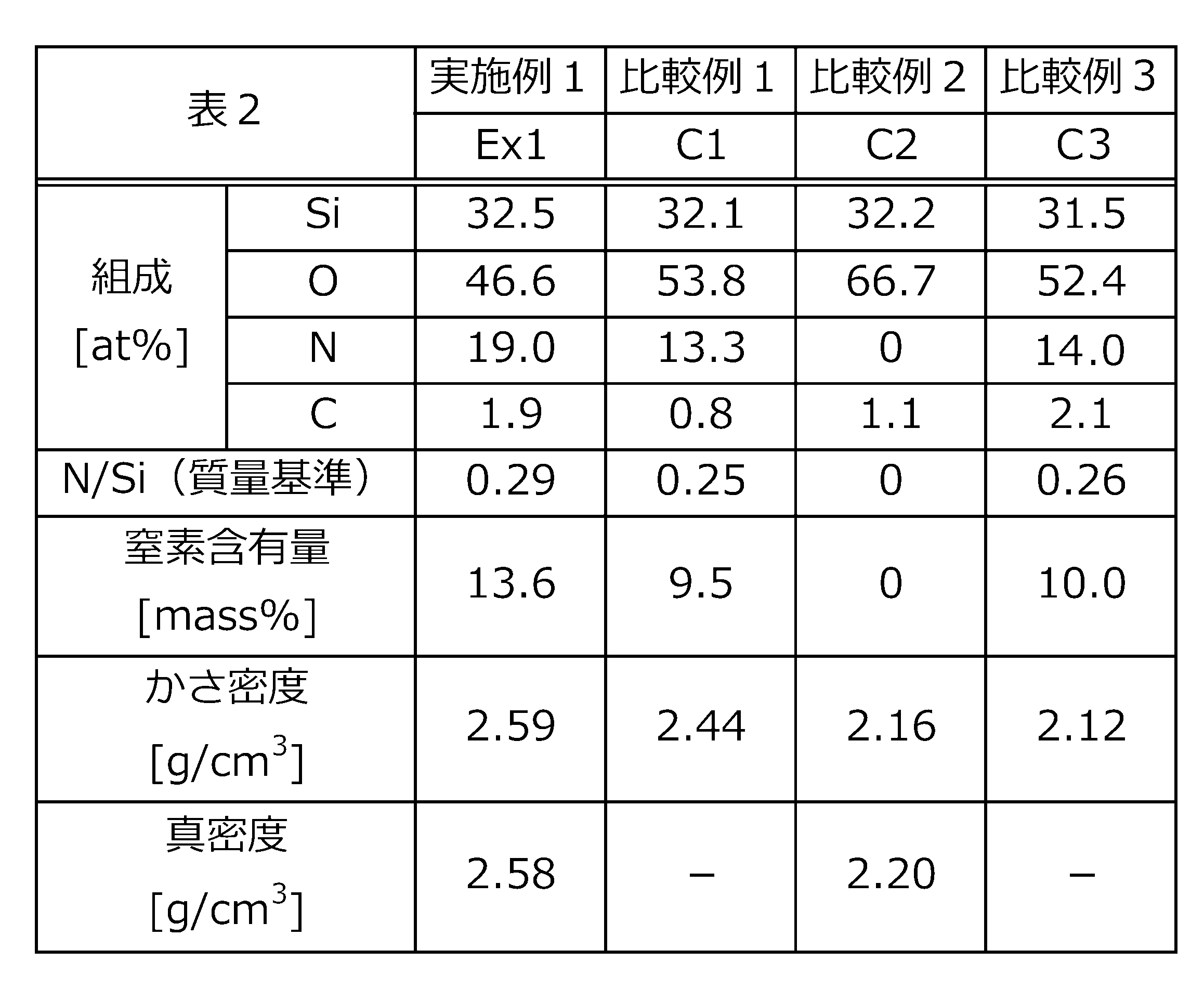
図10に示されたとおり、実施例1(「Ex1」、焼結温度:1600℃)、及び、比較例2(「C2」、シリカ粒子を1200℃で焼結したもの)では、透明な試料(バルク体)が得られた。一方、比較例1(C1、焼結温度:1500℃)、比較例3(C3、焼結温度:1400℃)では、透明な試料は得られなかった。
また、実施例2~4も同様に、透明な酸窒化ケイ素ガラス(バルク体)が得られた。一方、比較例1~15については、透明な酸窒化ケイ素ガラス(バルク体)は得られなかった。
また、実施例2~4も同様に、透明な酸窒化ケイ素ガラス(バルク体)が得られた。一方、比較例1~15については、透明な酸窒化ケイ素ガラス(バルク体)は得られなかった。
また、表1の結果から、実施例1、比較例1、及び、比較例3の試料については、原料粉に由来して、組成中に一定程度の窒素(N)が含まれており、実施例1では19.0原子%(at%)であった。一方、比較例2の試料では、窒素は検出されなかった。
また、かさ密度、及び、真密度の測定結果からは、実施例1、及び、比較例2の試料は相対密度が90%以上であり、いずれも均一なバルク体が得られたことが分かった。なお、表中「-」はデータ無し、又は、測定未実施であることを表している。
(光透過率測定)
光透過率は紫外-可視分光光度計(「SolidSpec-3700」、島津製作所製)、及び、フーリエ変換赤外(FT-IR)分光光度計(「SpectrumGX 2000R」、Perkin-Elmer製)を用いて測定した。なお、測定には直径6mmのマスクを用いた。紫外-可視分光光度計の測定パラメータは以下のとおりである。なお、測定値は、それぞれ試料の厚みを1.94mmとして補正した。使用されたそれぞれの試料の厚みは、表8に記載されている。
光透過率は紫外-可視分光光度計(「SolidSpec-3700」、島津製作所製)、及び、フーリエ変換赤外(FT-IR)分光光度計(「SpectrumGX 2000R」、Perkin-Elmer製)を用いて測定した。なお、測定には直径6mmのマスクを用いた。紫外-可視分光光度計の測定パラメータは以下のとおりである。なお、測定値は、それぞれ試料の厚みを1.94mmとして補正した。使用されたそれぞれの試料の厚みは、表8に記載されている。
スリット幅:2.0mm
スキャンスピード:中速
サンプリングピッチ:1.00nm
グレーティング切替波長:870nm
光源切替波長:310nm
検出器切替波長:830、1650nm
スキャンスピード:中速
サンプリングピッチ:1.00nm
グレーティング切替波長:870nm
光源切替波長:310nm
検出器切替波長:830、1650nm
また、フーリエ変換赤外(FT-IR)分光光度計の測定パラメータは以下のとおりである。
Resolution:2.00cm-1
Interval:0.5cm-1
Beam Splitter:KBr
Number of Scans:10
Interval:0.5cm-1
Beam Splitter:KBr
Number of Scans:10
図7は紫外-可視分光光度計による透過スペクトルであり、図8は、FT-IR分光光度計による透過スペクトルである。なお、各スペクトルは厚みの補正前のものであり、各試料の厚みは、表8に記載されている。
図中、R3とあるのは、市販のシリカガラス(信越化学製合成石英ガラス「Viosil-SQ」、酸窒化ケイ素ガラスではない、厚み2.00mm)の測定結果である。図3の結果から、実施例1(Ex1、焼結温度1600℃)の試料は、波長400~700nmの領域の光の透過率(厚み1.94mm換算)が50%以上(53%以上)であることがわかった。
また、図8の結果から、実施例1の試料は、波長2000~2500nmの領域の光の透過率(厚み1.94mm換算)が80%以上であることがわかった。これに対し、比較例1(「C1」、焼結温度:1500℃)、及び、比較例2(「C2」、シリカ粒子を1200℃で焼結したもの)の試料は、分子中のヒドロキシ基に由来する吸収ピークが存在し、比較例1(「C1」)では、透過率(厚み1.94mm換算)が70%程度となる領域、比較例2(「C2」)では、透過率が40%程度となる領域が存在した。
また、実施例1の試料は、波長2500nmを超えて、2875nmの領域の光の透過率(厚み1.94mm換算)が75%以上であることがわかった。これに対し、比較例1(「C1」、焼結温度:1500℃)、及び、比較例2(「C2」、シリカ粒子を焼結したもの)の試料は、分子中のヒドロキシ基に由来する吸収ピークが存在し、比較例1(C1)の試料では、透過率が70%未満となる領域、比較例2の試料では、ほとんど透過しない領域が存在した。また、R3(市販のシリカガラス)と比較しても、実施例1はより優れた透過率を有することがわかった。
上記から、実施例1の試料は、波長2000~2850nmの広い領域において、高い透過率を有し、従来、シリカガラスに対して行われていたヒドロキシ基の低減方法とは異なる、簡便な方法によって、この領域の光に対する透明性を確保することができることがわかった。
(屈折率測定)
屈折率の測定には分光エリプソメーター(「M-2000U」、J.A.Woollam製)を用いた。入射角は50~80°の範囲で10°毎に250-1000nmの波長領域を測定した。積算回数を40回、入射光偏光角を45°とした。
屈折率の測定には分光エリプソメーター(「M-2000U」、J.A.Woollam製)を用いた。入射角は50~80°の範囲で10°毎に250-1000nmの波長領域を測定した。積算回数を40回、入射光偏光角を45°とした。
図9は、屈折率の測定結果を表す図である。なお、スペクトルは厚みの補正前のものであり、各試料の厚みは、表8に記載されている。
図9の結果から実施例1の試料(「Ex1」、焼結温度:1600℃)は、波長400~700nmの領域における屈折率が、1.63以上であることがわかった。一方で、比較例2(C2)の試料では、1.50~1.60程度、市販のシリカガラスである「R3」(厚み2.00mm)は、1.44~1.51程度であることがわかった。実施例1の試料(「Ex1」)は広い波長領域にわたって、高い屈折率を有していることがわかった。
図9の結果から実施例1の試料(「Ex1」、焼結温度:1600℃)は、波長400~700nmの領域における屈折率が、1.63以上であることがわかった。一方で、比較例2(C2)の試料では、1.50~1.60程度、市販のシリカガラスである「R3」(厚み2.00mm)は、1.44~1.51程度であることがわかった。実施例1の試料(「Ex1」)は広い波長領域にわたって、高い屈折率を有していることがわかった。
(熱物性測定)
熱拡散率/熱伝導率測定装置(「LFA447」、NETZSCH Japan K.K.製)を用い、比熱、熱拡散率、及び、熱伝導率を測定した。光透過を防ぐため、試料表面をカーボンスプレーでコーティングして測定した。得られた温度上昇曲線に有限パルス幅補正を行い、Cowanモデルを用いて熱拡散率αを算出した。比熱容量Cpの計算には標準試料としてPylexを用いた。かさ密度(kg/m3)をρとして、熱伝導率κは次の式:κ=αρCpで算出した。表3はその結果である。
熱拡散率/熱伝導率測定装置(「LFA447」、NETZSCH Japan K.K.製)を用い、比熱、熱拡散率、及び、熱伝導率を測定した。光透過を防ぐため、試料表面をカーボンスプレーでコーティングして測定した。得られた温度上昇曲線に有限パルス幅補正を行い、Cowanモデルを用いて熱拡散率αを算出した。比熱容量Cpの計算には標準試料としてPylexを用いた。かさ密度(kg/m3)をρとして、熱伝導率κは次の式:κ=αρCpで算出した。表3はその結果である。
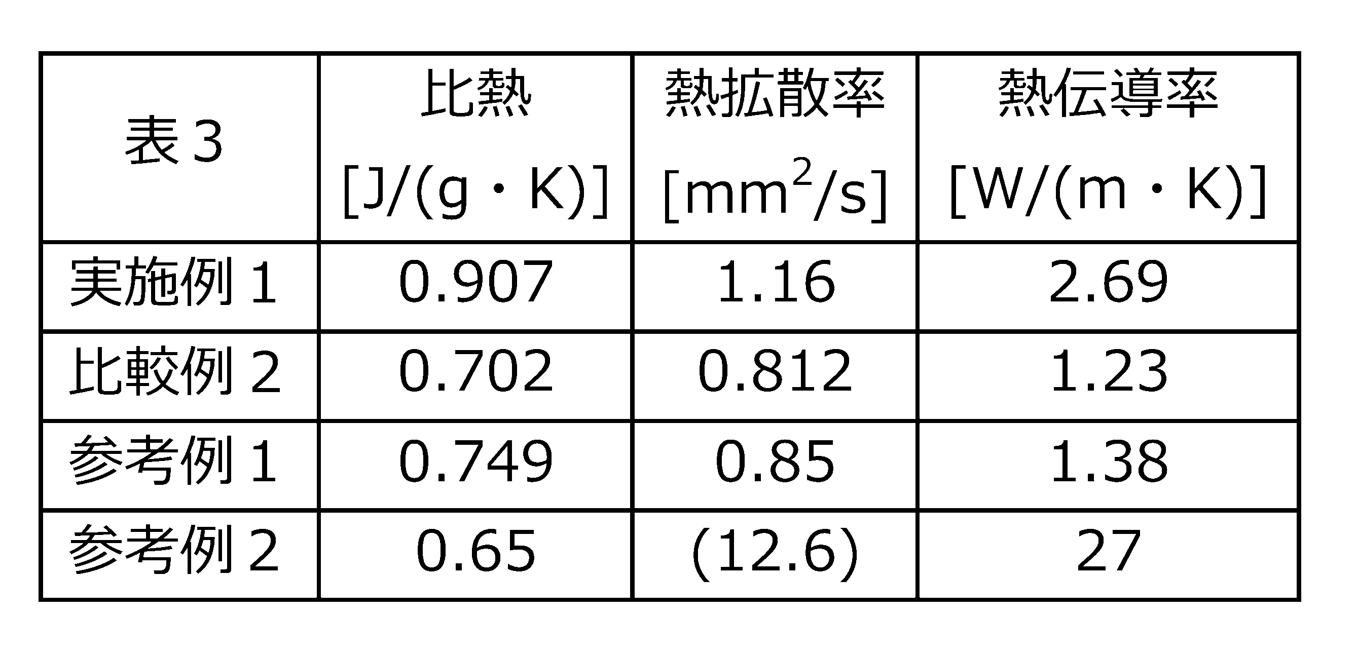
なお、表3中、参考例1とあるのは、東ソー株式会社製のシリカガラス(「ES」、SiCl4を酸水素炎にて加水分解・溶融して得られた合成石英ガラス)の文献値(表4も同様)である。また、参考例2とあるのは、京セラ製のSi3N4(SN-240)の文献値(表4も同様)である。また、表中(括弧)で括った数値は、計算値である。
表3の結果から、実施例1の試料は、比較例2、及び、参考例1の試料と比較してより大きな比熱、より大きな熱拡散率、及び、より大きな熱伝導率を有していることがわかった。
(ヤング率測定)
ヤング率は、超音波パルス法を用いて測定した。試料に接着させたバッファーロッドを通して超音波(縦波と横波)を伝搬させ、オシロスコープによって得られた波形から波の往復時間(縦波時間tl、横波時間tt)を読み取り、サンプル厚さLから波の伝搬速度(V=L/2×1/t)を算出した。さらに得られた波の伝搬速度を用いて次式よりポアソン比ν、剛性率Gp、及び、ヤング率Epを算出した。ただし、ρ:かさ密度(kg/m3)、Vl:縦波の速度(m/s)、Vt:横波の速度(m/s)である。
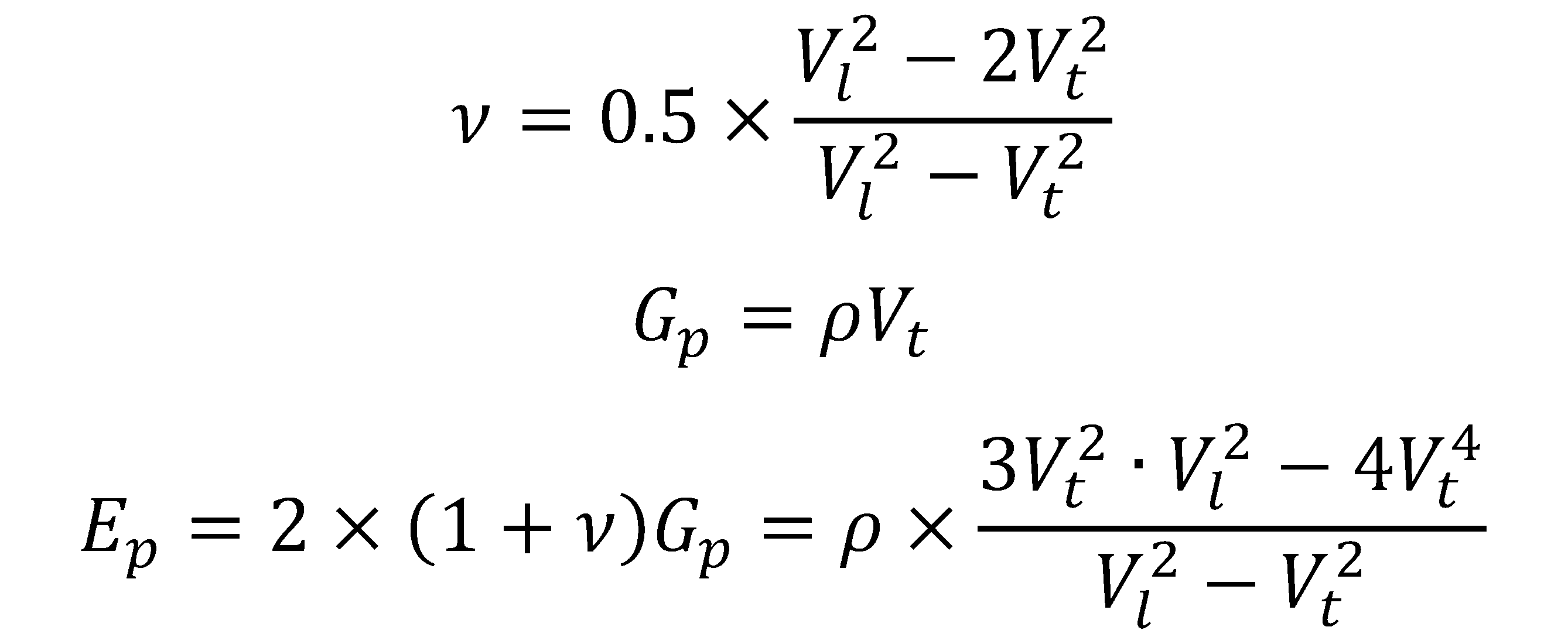
ヤング率は、超音波パルス法を用いて測定した。試料に接着させたバッファーロッドを通して超音波(縦波と横波)を伝搬させ、オシロスコープによって得られた波形から波の往復時間(縦波時間tl、横波時間tt)を読み取り、サンプル厚さLから波の伝搬速度(V=L/2×1/t)を算出した。さらに得られた波の伝搬速度を用いて次式よりポアソン比ν、剛性率Gp、及び、ヤング率Epを算出した。ただし、ρ:かさ密度(kg/m3)、Vl:縦波の速度(m/s)、Vt:横波の速度(m/s)である。
(ビッカース硬さ測定)
ビッカース硬さは、マイクロビッカース硬度計(「MVK-VL」、明石製作所製)を用いて測定した。試料表面にビッカース圧子を打ち込んだ。押し込み荷重は100gf、負荷時間を15secとした。除荷後、圧痕の対角線を測定し、その平均値からビッカース硬さを算出した。圧痕は光学顕微鏡(「ECLPSE LV100」、Nikon Solutions Co., Ltd.製)で観察した。
表4は、上記ヤング率の測定、及び、ビッカース硬さ測定の結果をまとめたものである。
ビッカース硬さは、マイクロビッカース硬度計(「MVK-VL」、明石製作所製)を用いて測定した。試料表面にビッカース圧子を打ち込んだ。押し込み荷重は100gf、負荷時間を15secとした。除荷後、圧痕の対角線を測定し、その平均値からビッカース硬さを算出した。圧痕は光学顕微鏡(「ECLPSE LV100」、Nikon Solutions Co., Ltd.製)で観察した。
表4は、上記ヤング率の測定、及び、ビッカース硬さ測定の結果をまとめたものである。
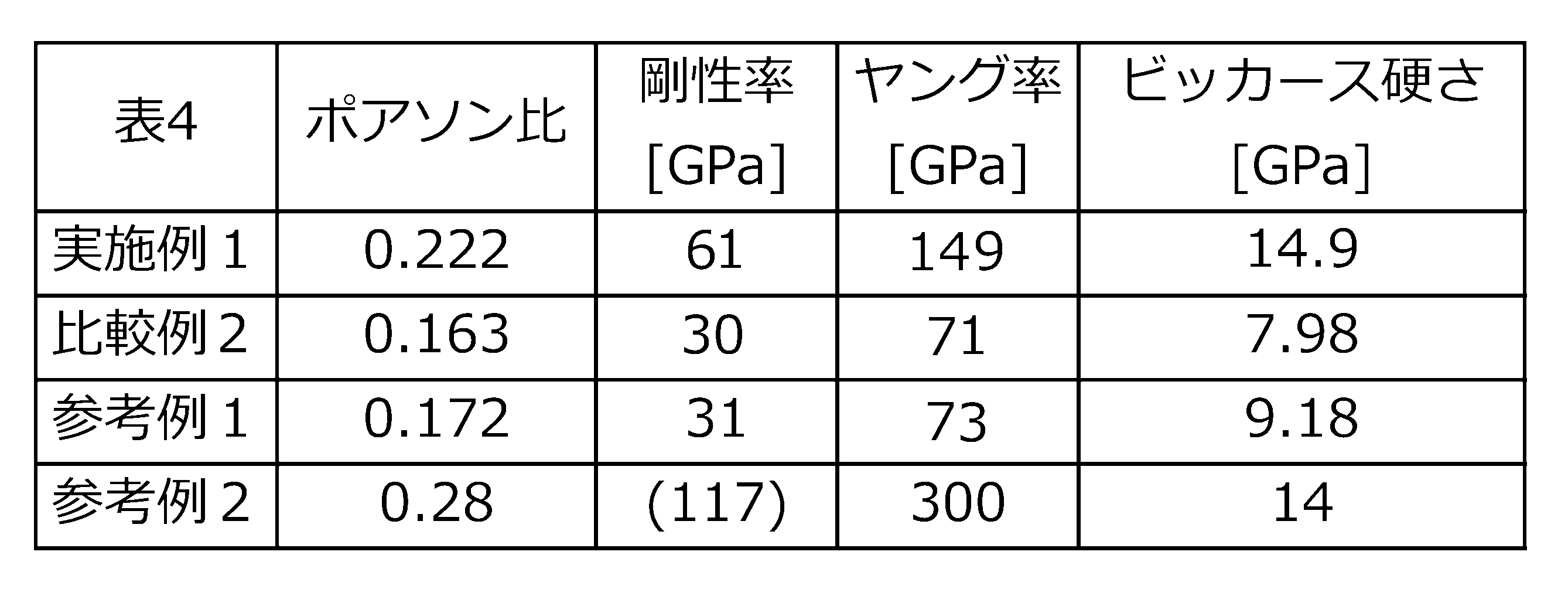
表4の結果から、実施例1の試料は、比較例2、及び、参考例1の試料と比較して、剛性率、ヤング率、及び、ビッカース硬さが大きく、約2倍以上であり、優れた機械特性を有することがわかった。
表7は、各実施例、比較例により得られた焼結体の組成、及び、物性の測定結果である。また、表8は、各実施例、比較例により得られた焼結体の光透過率の測定結果である。また、図11は、実施例2~4の酸窒化ケイ素ガラスの紫外-可視分光光度計による透過スペクトルである。また、図12は、実施例2~4の酸窒化ケイ素ガラスのフーリエ変換赤外分光光度計による透過スペクトルである。図中、実施例2~4は、それぞれ、「Ex2」、「Ex3」、「Ex4」と記載される。なお、結果の一部は、表2~4と重複する。
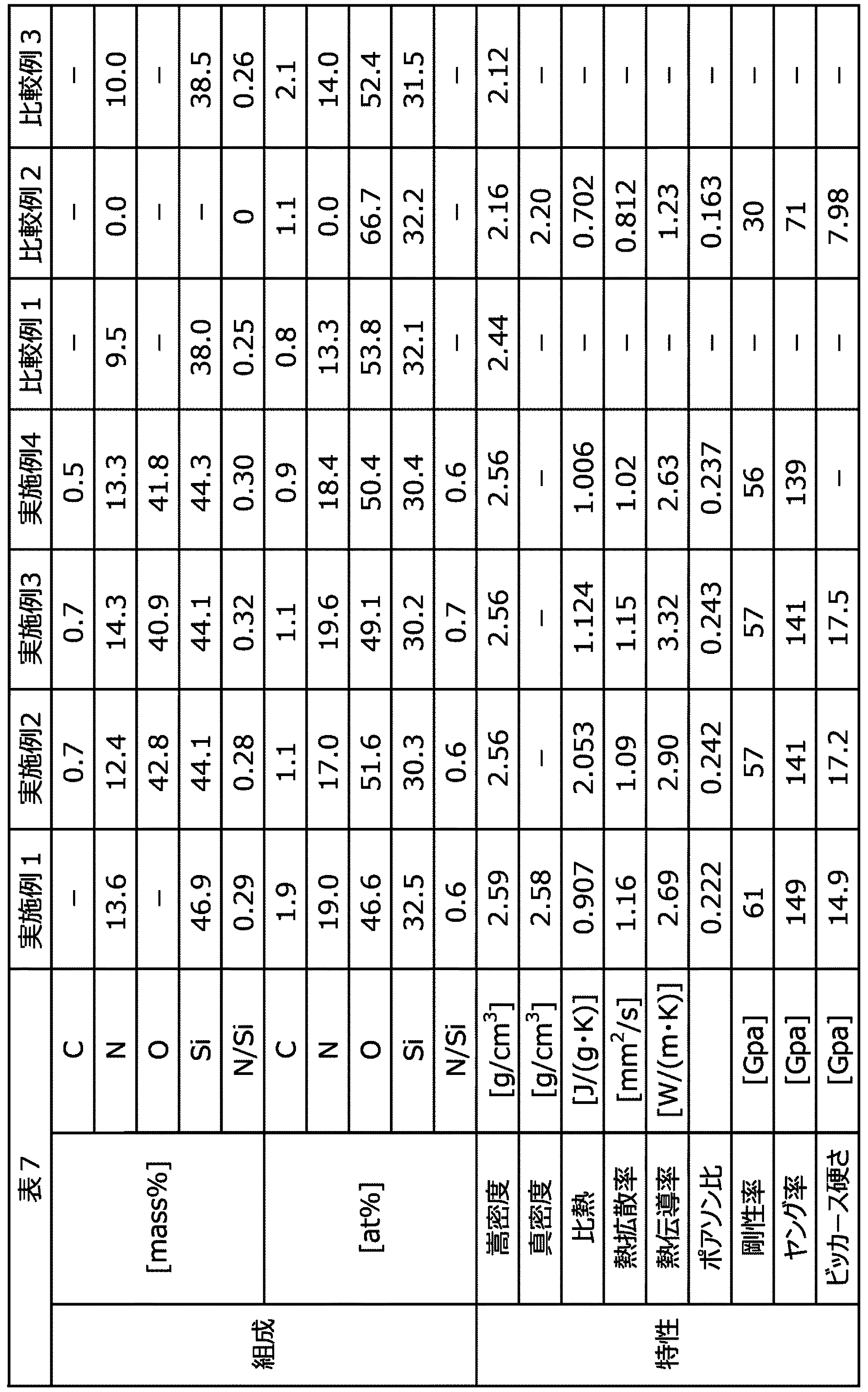
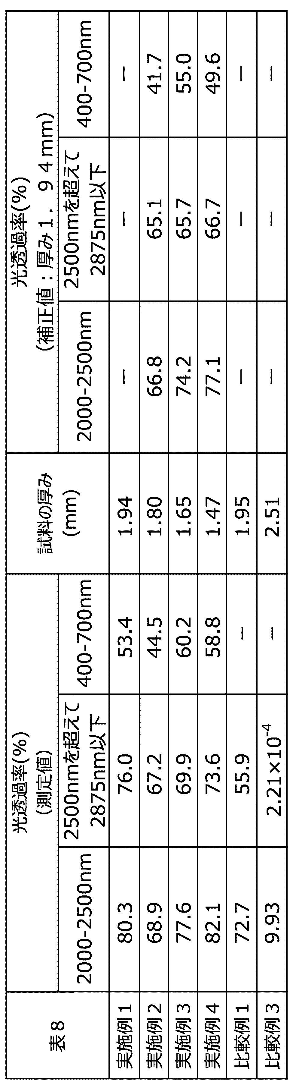
表7、及び、表8の結果から、1500℃超のSPSにより作製された実施例1~4の酸窒化ケイ素ガラスは、2000~2500μmにおける光の透過率が65%以上であることが明らかになった。また、窒素含有量が12.0質量%以上である実施例1~4の酸窒化ケイ素ガラスは、2000~2500μmにおける光の透過率が65%以上であることが明らかになった。
SPSの押圧力が70MPa以上とされた実施例1の酸窒化ケイ素ガラスは、実施例2の酸窒化ケイ素ガラスと比較して、より優れた光透過率(2000-2500nm、2500nmを超えて2875nm以下、400-700nm)を有していた。
11:電極、12:グラファイトパンチ、13:グラファイトダイ、14:カーボンシート、15:直流電源、16:チャンバ、20:試料、30:光導波路、31:コア、32:クラッド、40:赤外線イメージ炉、41:反射面、42、43:1/2楕円体ミラー、44:赤外線光源、45、46、55、65:赤外光、47、54、64:対象物、50:温度分布測定装置、51:対物レンズ、52:表示装置、53:赤外線カメラ、56:無線送信、60:放射温度計、61:バンドパスフィルタ、62:赤外線センサ、63:反射防止コート
Claims (16)
- シリカ粒子を加熱下でアンモニアガスと接触させることと、
前記接触させることにより得られた酸窒化ケイ素粒子を放電プラズマ焼結法により、1500℃を超える温度に加熱して焼結することと、を含む、酸窒化ケイ素ガラスの製造方法。 - 前記シリカ粒子の1次粒子の平均径が1000nm以下である、請求項1に記載の酸窒化ケイ素ガラスの製造方法。
- 前記酸窒化ケイ素粒子における、ケイ素原子の含有量に対する窒素原子の含有量の質量基準の含有量比が、0.10以上である、請求項1又は2に記載の酸窒化ケイ素ガラスの製造方法。
- 前記酸窒化ケイ素ガラスは、12.0質量%以上の窒素を含有し、波長2000~2500nmの領域における厚み1.94mmでの光透過率が65%以上である、請求項1~3のいずれか1項に記載の酸窒化ケイ素ガラスの製造方法。
- 請求項1~4のいずれか1項に記載の酸窒化ケイ素ガラスの製造方法を含む、赤外光を伝搬する光導波路の製造方法。
- 12.0質量%以上の窒素を含有し、波長2000~2500nmの領域における厚み1.94mmでの光透過率が65%以上である、酸窒化ケイ素ガラス。
- 波長400~700nmの領域における厚み1.94mmでの光透過率が50%以上である、請求項6に記載の酸窒化ケイ素ガラス。
- 熱伝導率が2.00W/(m・K)以上である、請求項6又は7に記載の酸窒化ケイ素ガラス。
- 波長2500nmを超えて、2875nm以下の領域における厚み1.94mmでの光透過率が65%以上である、請求項6~8のいずれか1項に記載の酸窒化ケイ素ガラス。
- 波長400~700nmの領域における屈折率が1.60以上である、請求項6~9のいずれか1項に記載の酸窒化ケイ素ガラス。
- ケイ素原子の含有量に対する窒素原子の含有量の質量基準の含有量比が、0.27以上である、請求項6~10のいずれか1項に記載の酸窒化ケイ素ガラス。
- ヤング率が100GPa以上である、請求項6~11のいずれか1項に記載の酸窒化ケイ素ガラス。
- 請求項6~12のいずれか1項に記載の酸窒化ケイ素ガラスを含む、赤外光を伝搬する光導波路。
- 請求項13に記載の光導波路を含む、赤外線イメージ炉。
- 請求項6~12のいずれか1項に記載の酸窒化ケイ素ガラスを含む、窓材。
- 請求項6~12のいずれか1項に記載の酸窒化ケイ素ガラスを含む、光学部材。
Priority Applications (1)
| Application Number | Priority Date | Filing Date | Title |
|---|---|---|---|
| JP2023574102A JP7750558B2 (ja) | 2022-01-17 | 2023-01-16 | 酸窒化ケイ素ガラスの製造方法、光導波路の製造方法、酸窒化ケイ素ガラス、光導波路、赤外線イメージ炉、窓材、及び、光学部材 |
Applications Claiming Priority (2)
| Application Number | Priority Date | Filing Date | Title |
|---|---|---|---|
| JP2022004873 | 2022-01-17 | ||
| JP2022-004873 | 2022-01-17 |
Publications (1)
| Publication Number | Publication Date |
|---|---|
| WO2023136349A1 true WO2023136349A1 (ja) | 2023-07-20 |
Family
ID=87279198
Family Applications (1)
| Application Number | Title | Priority Date | Filing Date |
|---|---|---|---|
| PCT/JP2023/001034 Ceased WO2023136349A1 (ja) | 2022-01-17 | 2023-01-16 | 酸窒化ケイ素ガラスの製造方法、光導波路の製造方法、酸窒化ケイ素ガラス、光導波路、赤外線イメージ炉、窓材、及び、光学部材 |
Country Status (2)
| Country | Link |
|---|---|
| JP (1) | JP7750558B2 (ja) |
| WO (1) | WO2023136349A1 (ja) |
Citations (3)
| Publication number | Priority date | Publication date | Assignee | Title |
|---|---|---|---|---|
| JPH01167255A (ja) * | 1987-12-24 | 1989-06-30 | Fujikura Ltd | オキシナイトガラスの製造方法 |
| JPH10502324A (ja) * | 1994-06-30 | 1998-03-03 | アルバート ロクスリィ、テッド | 焼結石英ガラス製品及びその製造方法 |
| JP2000143257A (ja) * | 1998-11-06 | 2000-05-23 | Sumitomo Electric Ind Ltd | ガラス物品の製造方法 |
-
2023
- 2023-01-16 JP JP2023574102A patent/JP7750558B2/ja active Active
- 2023-01-16 WO PCT/JP2023/001034 patent/WO2023136349A1/ja not_active Ceased
Patent Citations (3)
| Publication number | Priority date | Publication date | Assignee | Title |
|---|---|---|---|---|
| JPH01167255A (ja) * | 1987-12-24 | 1989-06-30 | Fujikura Ltd | オキシナイトガラスの製造方法 |
| JPH10502324A (ja) * | 1994-06-30 | 1998-03-03 | アルバート ロクスリィ、テッド | 焼結石英ガラス製品及びその製造方法 |
| JP2000143257A (ja) * | 1998-11-06 | 2000-05-23 | Sumitomo Electric Ind Ltd | ガラス物品の製造方法 |
Non-Patent Citations (2)
| Title |
|---|
| FAN LEI, SHI ZHONGQI, LU XUEFENG, WANG CHAO, CHEN MENG, LI YAWEN, WANG HONGJIE, RIEDEL: "Silicon Oxynitride Ceramics Prepared by Plasma Activated Sintering of Nanosized Amorphous Silicon Nitride Powder without Additives", JOURNAL OF THE AMERICAN CERAMIC SOCIETY, BLACKWELL PUBLISHING, MALDEN, MA., US, vol. 96, no. 8, 1 August 2013 (2013-08-01), US , pages 2358 - 2361, XP055845955, ISSN: 0002-7820, DOI: 10.1111/jace.12463 * |
| SJOBERG, J. ET AL.: "PREPARATION OF Si2N2O BASED SINTERED BODIES FROM POWDERS MADE BY NITRIDATION OF AMORPHOUS SILICA IN AMMONIA", HIGH TECH CERAM. A, 1987, pages 535 - 543, XP009547743 * |
Also Published As
| Publication number | Publication date |
|---|---|
| JPWO2023136349A1 (ja) | 2023-07-20 |
| JP7750558B2 (ja) | 2025-10-07 |
Similar Documents
| Publication | Publication Date | Title |
|---|---|---|
| Irifune et al. | Pressure-induced nano-crystallization of silicate garnets from glass | |
| Gautam et al. | Synthesis, IR and Raman spectroscopic studies of (Ba, Sr) TiO3 borosilicate glasses with addition of La2O3 | |
| Shaaban et al. | Electronic Polarizability, Optical Basicity, Thermal, Mechanical and Optical Investigations of (65B2O3–30Li2O–5Al2O3) Glasses Doped with Titanate: Kh. S. Shaaban, Wahab, ER Shaaban, Yousef, and Mahmoud | |
| JP5529369B2 (ja) | 熔融石英ガラスおよびその製造方法 | |
| JP4492123B2 (ja) | シリカガラス | |
| TWI335309B (en) | Synthetic silica glass optical material having high resistance to laser induced damage | |
| Sakai et al. | Enhanced second harmonic generation at surface in transparent nanocrystalline TeO 2-based glass ceramics | |
| Mohd Fudzi et al. | Linear optical properties of zinc borotellurite glass doped with lanthanum oxide nanoparticles for optoelectronic and photonic application | |
| CN108698887B (zh) | 由均质石英玻璃制得的玻璃纤维和预成形品 | |
| TW200417822A (en) | Reduced striae extreme ultraviolet elements | |
| Masuno et al. | Higher refractive index and lower wavelength dispersion of SiO2 glass by structural ordering evolution via densification at a higher temperature | |
| TW200533622A (en) | Photomask substrate made of synthetic quartz glass and photomask | |
| EP3524586A1 (en) | Transparent spinel sintered body, optical member and method for producing transparent spinel sintered body | |
| Cao et al. | Chalcogenide glass ceramics: a high-performing innovative infrared acousto-optic material | |
| EP1603843A2 (en) | Optical synthetic quartz glass and method for producing the same | |
| JP7750558B2 (ja) | 酸窒化ケイ素ガラスの製造方法、光導波路の製造方法、酸窒化ケイ素ガラス、光導波路、赤外線イメージ炉、窓材、及び、光学部材 | |
| KR101606225B1 (ko) | 포토마스크용 광학 부재 및 그 제조 방법 | |
| JPH0959034A (ja) | 合成石英ガラス材及びその製造方法 | |
| Kuzuu et al. | Temperature and hydroxyl concentration dependences of diffusion coefficients of hydroxyl groups in vitreous silica at temperatures of 850–1200 C | |
| Van et al. | Erbium-doped tin-silicate sol–gel-derived glass-ceramic thin films: effect of environment segregation on the Er3+ emission | |
| Nishikata et al. | Fabrication of silica glass for UV-transmission by gel-casting method | |
| Osawa et al. | Synthesis of bulk silicon oxynitride glass through nitridation of SiO2 aerogels and determination of T g | |
| Duverger et al. | Waveguide Raman spectroscopy: a non-destructive tool for the characterization of amorphous thin films | |
| Al-Nidawi et al. | Er2O3 doped zinc borosilicate glass substrate: Impact of doping to the structural, optical and surface plasmon resonance performance | |
| EA008276B1 (ru) | Способ формирования монокристаллической структуры и кремниевый материал, стойкий к воздействию н и он |
Legal Events
| Date | Code | Title | Description |
|---|---|---|---|
| 121 | Ep: the epo has been informed by wipo that ep was designated in this application |
Ref document number: 23740357 Country of ref document: EP Kind code of ref document: A1 |
|
| ENP | Entry into the national phase |
Ref document number: 2023574102 Country of ref document: JP Kind code of ref document: A |
|
| NENP | Non-entry into the national phase |
Ref country code: DE |
|
| 122 | Ep: pct application non-entry in european phase |
Ref document number: 23740357 Country of ref document: EP Kind code of ref document: A1 |