WO2023136305A1 - 穿刺針及び焼灼針装置 - Google Patents
穿刺針及び焼灼針装置 Download PDFInfo
- Publication number
- WO2023136305A1 WO2023136305A1 PCT/JP2023/000660 JP2023000660W WO2023136305A1 WO 2023136305 A1 WO2023136305 A1 WO 2023136305A1 JP 2023000660 W JP2023000660 W JP 2023000660W WO 2023136305 A1 WO2023136305 A1 WO 2023136305A1
- Authority
- WO
- WIPO (PCT)
- Prior art keywords
- needle
- tip
- lumen
- axis
- puncture needle
- Prior art date
- Legal status (The legal status is an assumption and is not a legal conclusion. Google has not performed a legal analysis and makes no representation as to the accuracy of the status listed.)
- Ceased
Links
Images



Classifications
-
- A—HUMAN NECESSITIES
- A61—MEDICAL OR VETERINARY SCIENCE; HYGIENE
- A61B—DIAGNOSIS; SURGERY; IDENTIFICATION
- A61B18/00—Surgical instruments, devices or methods for transferring non-mechanical forms of energy to or from the body
- A61B18/18—Surgical instruments, devices or methods for transferring non-mechanical forms of energy to or from the body by applying electromagnetic radiation, e.g. microwaves
- A61B18/20—Surgical instruments, devices or methods for transferring non-mechanical forms of energy to or from the body by applying electromagnetic radiation, e.g. microwaves using laser
- A61B18/22—Surgical instruments, devices or methods for transferring non-mechanical forms of energy to or from the body by applying electromagnetic radiation, e.g. microwaves using laser the beam being directed along or through a flexible conduit, e.g. an optical fibre; Couplings or hand-pieces therefor
Definitions
- the present disclosure relates to a puncture needle and a cautery needle device.
- Patent Document 1 Japanese Patent Application Laid-Open No. 2019-208962 (Patent Document 1) describes a device for inducing follicle growth.
- the follicle growth induction device includes an ovary puncture needle that punctures the ovary to form a puncture hole, and an optical fiber that guides laser light emitted from the laser generator.
- the ovary puncture needle consists of a proximal end, a body supported by the proximal end, and a needle tube connected to the body and having a needle tip for puncturing the ovary. It is left inside the needle cannula so that it is located nearby.
- the tip of the needle is heated by laser light emitted through an optical fiber.
- the needle tip of the needle tip portion of the ovary puncture needle is arranged at a position deviating from the axis or the center of the needle tube.
- the tip of the needle tip portion is located at a position deviating from the axis or center of the needle tube, there were cases where it was not possible to puncture the affected area accurately.
- the tip of the needle tip portion is arranged at a position deviated from the axis or the center of the needle tube, the tip of the optical fiber (hereinafter referred to as laser fiber) that guides the laser light is placed at the tip of the needle tip portion. can't get close enough.
- the tip of the laser fiber cannot be placed directly behind the tip of the needle, nor can the tip of the laser fiber be guided to just before the tip of the needle. Therefore, the tip of the needle tip portion cannot be heated sufficiently by the laser beam in some cases. Insufficient heating of the tip of the needle tip may result in insufficient hemostasis around the needle tip. Therefore, it is desired to provide a puncture needle and a cautery needle device that can accurately puncture an affected area and can appropriately heat the tip of the needle tip.
- the present disclosure has been made in view of such circumstances, and an object thereof is to provide a puncture needle and a cauterization needle device capable of accurately puncturing an affected area and appropriately heating the tip of the needle tip. It is in.
- the puncture needle according to the present disclosure for achieving the above object is a tubular body having a lumen; a needle tip portion formed at the tip portion of the body portion, The needle tip closes the tip of the lumen, The needle tip of the needle tip portion overlaps with the axis of the body portion.
- the puncture needle according to the present disclosure further comprises A distal end of the lumen may be arranged inside the needle tip portion in a direction along the axis.
- the puncture needle according to the present disclosure further comprises
- the distal end of the lumen is overlaps with the axis, It may have a shape that tapers toward the tip side.
- the puncture needle according to the present disclosure further comprises
- the tip portion may have a polygonal pyramid shape.
- An ablation needle device for achieving the above object includes: a puncture needle having a cylindrical main body portion having a lumen and a needle tip portion formed at the distal end portion of the main body portion; and a laser fiber capable of irradiating a laser serving as a heat source from the tip, The needle tip closes the tip of the lumen, the needle tip of the needle tip portion overlaps with the axis of the body portion, The laser fiber is inserted through the lumen, and is capable of heating the needle tip via a closing portion that closes the lumen.
- the cautery needle device further includes: The distal end of the lumen is overlaps with the axis, It has a shape that tapers toward the tip side, a tip of the lumen is arranged inside the needle tip portion in a direction along the axis; the tip of the needle and the tip of the lumen overlap when viewed in a direction along the axis; The laser fiber is positioned so as to overlap the tip of the needle when viewed in the direction along the axis due to the constricted shape in a state of being inserted into the lumen.
- the needle tip portion may be heated directly from behind.
- a puncture needle and a cautery needle device capable of accurately puncturing an affected area and appropriately heating the tip of the needle tip.
- FIG. 1 is a side view of a cautery needle device provided with a puncture needle according to this embodiment;
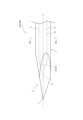
- FIG. Fig. 3 is an enlarged view of the vicinity of the tip of the puncture needle; 3 is a cross-sectional view taken along line III-III of FIG. 2;
- FIG. 10 is an enlarged view of the vicinity of the tip of the puncture needle of Modification 1;
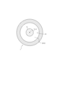
- FIG. 5 is a cross-sectional view taken along line VV of FIG. 4;
- FIG. 11 is an enlarged view of the vicinity of the tip of the puncture needle of Modification 2;
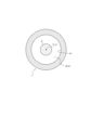
- FIG. 7 is a cross-sectional view taken along line VII-VII of FIG. 6;
- FIG. 1 shows a cautery needle device 200 having a puncture needle 100 and a laser fiber 9 according to this embodiment.
- the puncture needle 100 includes a cylindrical body portion 1 having a lumen S and a needle tip portion 2 formed at the distal end portion of the body portion 1 .
- the needle tip portion 2 closes the tip of the lumen S, and the needle tip T of the needle tip portion 2 overlaps with the axis G of the main body portion 1 .
- the laser fiber 9 is a member that forms an optical path, such as an optical fiber that can irradiate a laser serving as a heat source from its tip.
- a laser light source (not shown) for irradiating a laser beam to the optical path of the laser fiber 9 is connected to the proximal end of the laser fiber 9 .
- the puncture needle 100 is heated at the base end side of the needle tip portion 2 inside the lumen S by the laser light supplied from the laser fiber 9 . Then, the heat supplied to the needle tip portion 2 can heat or cauterize the affected area.
- the cauterization needle device 200 using the puncture needle 100 can accurately puncture the affected area with the puncture needle 100 as described later.
- the tip of the needle tip portion 2 can be appropriately heated according to the purpose of treatment of the affected area.
- the puncture needle 100 can be suitably used as an ovary puncture needle, for example.
- the cautery needle device 200 can be suitably used as a follicle growth induction device.
- the uses of the puncture needle 100 and the cautery needle device 200 are not limited to these.
- the main body 1 is, for example, cylindrical.
- a space defined by an inner wall 10 inside the cylinder of the main body 1 is a lumen S.
- FIG. 1 A space defined by an inner wall 10 inside the cylinder of the main body 1 is a lumen S.
- the main body 1 is preferably made of a material with high thermal conductivity, such as metal such as stainless steel, titanium, titanium alloy, cobalt-chromium alloy, or metal alloy.
- the main body 1 is made of stainless steel.
- the needle tip portion 2 is formed at the tip of the body portion 1 as described above, and has, for example, a conical shape.
- An example of the pyramidal shape is a conical shape or a polypyramidal shape including a plurality of plane portions on the side surface.
- Examples of the polygonal pyramid shape are a triangular pyramid shape, a square pyramid shape, and a pyramid shape with five or more angles.
- FIGS. 1 and 2 illustrate an example in which the needle tip portion 2 has a triangular pyramid shape. Note that FIG. 2 shows an enlarged view of the vicinity of the needle tip portion 2 of the puncture needle 100 .
- the needle tip T of the needle tip portion 2 overlaps with the axis G of the main body portion 1, as shown in FIGS.
- the puncture needle 100 can puncture the affected area accurately regardless of the position of the needle tip portion 2 in the circumferential direction around the axis G. That is, if the needle tip T does not overlap the axis G of the puncture needle 100, the point of puncture will deviate from the axis G of the puncture needle 100 during puncture using the puncture needle 100. Since the needle tip T is located at a position overlapping the axis G, the affected part can be punctured accurately.
- the lumen S is a space continuously formed along the axis G inside the main body 1 .
- the lumen S is formed as a columnar space whose axis overlaps with the axis G and whose cross section perpendicular to the axis G has a circular shape.
- the needle tip portion 2 closes the tip of the lumen S.
- a part of the inner wall 10 of the main body 1 which is located inside the needle tip 2 and closes the lumen S, is referred to as a closing portion 29 . That is, the body portion 1 is formed in a bottomed tubular shape in which the inner wall 10 on the distal end side of the lumen S is closed by the closing portion 29 serving as the tubular bottom.
- the lumen S is formed in the body portion 1 to reach the inside of the needle tip portion 2 . That is, the distal end of the lumen S is arranged inside the needle tip portion 2 in the direction along the axis G. As shown in FIG. As a result, the needle tip portion 2 can be heated from the inside, and the efficiency of supplying heat to the affected area is improved. For example, since the amount of heat that escapes due to heat transfer to the body portion 1 can be reduced, the temperature of the probe tip portion 2 can be quickly raised to a desired temperature. If the efficiency of heat supply to the affected area is improved, minimally invasive procedures can be realized, such as quick hemostasis at the affected area, or instantaneous cauterization of only the affected area while reducing damage to other areas.
- the tip of the lumen S should be overlapped with the axis G.
- the tip Ts of the lumen S is overlapped with the axis G. This makes it easier for the laser fiber 9 to be arranged at a position overlapping the axis G.
- the needle tip portion 2 is evenly inserted into the laser fiber. 9 can be heated.
- the lumen S should preferably have a shape that tapers toward the tip side. As a result, when the laser fiber 9 is pushed to the tip of the lumen S, the laser fiber 9 is naturally positioned at a position overlapping the axis G. As shown in FIG.
- the shape of the lumen S that tapers toward the distal end side (hereinafter, may be referred to as the “tip constricted shape of the lumen S”) is defined as The tip of S, ie, the closing portion 29, is illustrated as having a conical shape.
- the tip of S ie, the closing portion 29, is illustrated as having a conical shape.
- a lumen S is formed extending from the body portion 1 to the inside of the needle tip portion 2, and the tip Ts of the lumen S overlaps with the axis G. Therefore, the laser fiber 9 can heat the needle tip portion 2 directly behind the needle tip portion 2 .
- the cauterization needle device 200 using the puncture needle 100 requires an appropriate temperature rise up to the needle tip T according to the purpose of treatment of the affected area. If the temperature of puncture needle 100 is not properly increased to needle tip T, it may become difficult to form a solidified layer around needle tip portion 2 . Therefore, the risk of bleeding easily increases in some cases. In the cautery needle device 200, if the lumen S into which the laser fiber 9 is inserted is not formed close to the needle tip T, thermal conductivity tends to deteriorate, and the temperature of the needle tip T may not rise sufficiently.
- the needle tip portion 2 since the lumen S is formed from the body portion 1 to the inside of the needle tip portion 2 and the tip Ts of the lumen S overlaps with the axis G, the needle tip portion 2 In particular, since the laser can be irradiated directly behind the needle tip T, the temperature of the needle tip T can be raised appropriately.
- FIG. 3 is a cross-sectional view taken along line III-III in FIG.
- the tip concavity shape of the lumen S can take shapes other than a conical shape.
- the concavity shape at the tip of the lumen S may be changed to a conical shape, and may be a polygonal pyramid shape, a hemispherical shape, or a similar shape.
- Modification 1 4 and 5 show, as the shape of the tip of the lumen S, the needle tip of the puncture needle 100 when the tip portion of the lumen S, that is, the closing portion 29 has a triangular pyramid shape (an example of a polygonal pyramid shape). The figure which expanded the vicinity of the part 2 is shown. 5 is a cross-sectional view taken along line VV in FIG.
- Modification 2 6 and 7 show, as the shape of the tip of the lumen S, a puncture needle in which the tip portion of the lumen S, that is, the closing portion 29 has an elliptical hemispherical shape (an example of a hemispherical shape or similar shape).
- the figure which expanded the vicinity of the needle tip part 2 in 100 is shown.
- 7 is a cross-sectional view taken along line VII--VII in FIG.
- Other examples of hemispherical or similar shapes include oblong hemispherical shapes and shapes with cross-sections that are parabolic or hyperbolic.
- the main body 1 is made of a metal such as stainless steel or a metal alloy. Formation is not excluded. bottom.
- the lumen S is formed as a cylindrical space, but the lumen S can also be elliptical or prismatic.
- the puncture needle 100 has one lumen S, but the puncture needle 100 may have a lumen other than the lumen S. There may be.
- the cauterization needle device 200 includes the puncture needle 100 and the laser fiber 9.
- the cauterization needle device 200 may be a rod-shaped or cylindrical A member may further be provided.
- the present disclosure is applicable to puncture needles and cautery needle devices.
Landscapes
- Health & Medical Sciences (AREA)
- Surgery (AREA)
- Physics & Mathematics (AREA)
- Life Sciences & Earth Sciences (AREA)
- Engineering & Computer Science (AREA)
- Medical Informatics (AREA)
- Nuclear Medicine, Radiotherapy & Molecular Imaging (AREA)
- Electromagnetism (AREA)
- Optics & Photonics (AREA)
- Biomedical Technology (AREA)
- Heart & Thoracic Surgery (AREA)
- Otolaryngology (AREA)
- Molecular Biology (AREA)
- Animal Behavior & Ethology (AREA)
- General Health & Medical Sciences (AREA)
- Public Health (AREA)
- Veterinary Medicine (AREA)
- Surgical Instruments (AREA)
Abstract
患部を正確に穿刺でき、且つ、針先部の先端を適切に加熱できる穿刺針及び焼灼針装置を提供するべく、穿刺針(100)は、内腔(S)を有する筒状の本体部(1)と、本体部(1)の先端部に形成された針先部(2)と、を備え、針先部(2)は、内腔(S)の先端(Ts)を閉止し、針先部(2)の針先端(T)は、本体部(1)の軸心(G)と重複しているように構成した。
Description
本開示は、穿刺針及び焼灼針装置に関する。
特開2019-208962号公報(特許文献1)には、卵胞発育誘導装置が記載されている。卵胞発育誘導装置は、卵巣を穿刺し穿刺孔を形成する卵巣穿刺針と、レーザ発生装置から出射されるレーザ光を導く光ファイバとを備えている。卵巣穿刺針は、基端部と、基端部に支持される体部と、体部に連なり卵巣を穿刺する針先部からなる針管と、からなり、光ファイバは、先端が針先部の付近に位置するように、針管の内部に留置される。針先部は、光ファイバを介して導かれた、レーザ光の出射によって加熱されるようになっている。卵巣穿刺針の針先部の針先は、針管の軸心又は中心から反れた位置に配置されている。
上記のような従来の穿刺針にあっては、針先部の針先が針管の軸心又は中心から反れた位置に配置されているため、正確に患部を穿刺できない場合があった。また、針先部の針先が針管の軸心又は中心から反れた位置に配置されているため、レーザ光を導く光ファイバ(以下、レーザファイバと称する)の先端を針先部の針先に十分近づけることができない。例えば、レーザファイバの先端を、針先の真後ろに配置することができないし、レーザファイバの先端を針先の手前まで導くこともできない。そのため、レーザ光による針先部の先端の加熱が十分に行えない場合があった。針先部の先端の加熱が十分に行えないと、針先周辺での止血が十分に行えない場合も生じうる。そこで、患部を正確に穿刺でき、且つ、針先部の先端を適切に加熱できる穿刺針及び焼灼針装置の提供が望まれる。
本開示は、かかる実状に鑑みて為されたものであって、その目的は、患部を正確に穿刺でき、且つ、針先部の先端を適切に加熱できる穿刺針及び焼灼針装置を提供することにある。
上記目的を達成するための本開示に係る穿刺針は、
内腔を有する筒状の本体部と、
前記本体部の先端部に形成された針先部と、を備え、
前記針先部は、前記内腔の先端を閉止し、
前記針先部の針先端は、前記本体部の軸心と重複している。
内腔を有する筒状の本体部と、
前記本体部の先端部に形成された針先部と、を備え、
前記針先部は、前記内腔の先端を閉止し、
前記針先部の針先端は、前記本体部の軸心と重複している。
本開示に係る穿刺針は、更に、
前記内腔の先端は、前記軸心に沿う方向において、前記針先部の内側に配置されていてもよい。
前記内腔の先端は、前記軸心に沿う方向において、前記針先部の内側に配置されていてもよい。
本開示に係る穿刺針は、更に、
前記内腔の先端部は、
前記軸心と重複しており、
先端側に向けてすぼむ形状とされていてもよい。
前記内腔の先端部は、
前記軸心と重複しており、
先端側に向けてすぼむ形状とされていてもよい。
本開示に係る穿刺針は、更に、
前記針先部は、多角錘形状であってもよい。
前記針先部は、多角錘形状であってもよい。
上記目的を達成するための本開示に係る焼灼針装置は、
内腔を有する筒状の本体部と、前記本体部の先端部に形成された針先部と、を有する穿刺針と、
先端から熱源となるレーザを照射可能なレーザファイバと、を備え、
前記針先部は、前記内腔の先端を閉止し、
前記針先部の針先端は、前記本体部の軸心と重複しており、
前記レーザファイバは、前記内腔に挿通されており、前記内腔を閉止する閉止部を介して前記針先部を加熱可能とされている。
内腔を有する筒状の本体部と、前記本体部の先端部に形成された針先部と、を有する穿刺針と、
先端から熱源となるレーザを照射可能なレーザファイバと、を備え、
前記針先部は、前記内腔の先端を閉止し、
前記針先部の針先端は、前記本体部の軸心と重複しており、
前記レーザファイバは、前記内腔に挿通されており、前記内腔を閉止する閉止部を介して前記針先部を加熱可能とされている。
本開示に係る焼灼針装置は、更に、
前記内腔の先端部は、
前記軸心と重複しており、
先端側に向けてすぼむ形状とされており、
前記内腔の先端は、前記軸心に沿う方向において、前記針先部の内側に配置されており、
前記針先端と前記内腔の先端とは、前記軸心に沿う方向で見た場合に重複しており、
前記レーザファイバは、前記内腔に挿通された状態で、前記すぼむ形状により、前記軸心に沿う方向で見た場合に前記針先端と重複するように位置決めされて、前記針先部の真後ろから前記針先部を加熱可能とされていてもよい。
前記内腔の先端部は、
前記軸心と重複しており、
先端側に向けてすぼむ形状とされており、
前記内腔の先端は、前記軸心に沿う方向において、前記針先部の内側に配置されており、
前記針先端と前記内腔の先端とは、前記軸心に沿う方向で見た場合に重複しており、
前記レーザファイバは、前記内腔に挿通された状態で、前記すぼむ形状により、前記軸心に沿う方向で見た場合に前記針先端と重複するように位置決めされて、前記針先部の真後ろから前記針先部を加熱可能とされていてもよい。
本開示によれば、患部を正確に穿刺でき、且つ、針先部の先端を適切に加熱できる穿刺針及び焼灼針装置を提供することができる。
図面に基づいて、本開示の実施形態に係る穿刺針及び焼灼針装置について説明する。
(概要の説明)
図1には、本実施形態に係る穿刺針100とレーザファイバ9とを備えた焼灼針装置200を示している。
図1には、本実施形態に係る穿刺針100とレーザファイバ9とを備えた焼灼針装置200を示している。
穿刺針100は、内腔Sを有する筒状の本体部1と、本体部1の先端部に形成された針先部2と、を備えている。針先部2は、内腔Sの先端を閉止し、針先部2の針先端Tは、本体部1の軸心Gと重複している。
レーザファイバ9は、先端から熱源となるレーザを照射可能な光ファイバなどの光路を形成する部材である。レーザファイバ9の基端側には、レーザファイバ9の光路にレーザ光を照射するレーザ光源(図示せず)が接続されている。
穿刺針100は、レーザファイバ9から供給されたレーザ光により、内腔S内における、針先部2の基端側を加熱される。そして、針先部2に供給された熱により、患部を加熱又は焼灼することができる。
穿刺針100を用いた焼灼針装置200では、後述するように、穿刺針100で患部を正確に穿刺できる。また、患部の治療目的に応じて針先部2の先端を適切に加熱できる。
穿刺針100は、例えば、卵巣穿刺針として好適に用いることができる。また、焼灼針装置200は卵胞発育誘導装置として好適に用いることができる。なお、穿刺針100及び焼灼針装置200の用途は、これらに限定されるものではない。
(各部の説明)
以下、穿刺針100及びこれを用いた焼灼針装置200の各部について説明する。
以下、穿刺針100及びこれを用いた焼灼針装置200の各部について説明する。
図1に示すように、本体部1は、例えば円柱状の筒状である。本体部1の筒内部の内壁10で区画された空間が内腔Sである。
本体部1は、例えばステンレスやチタン、チタン合金、コバルト-クロム合金などの金属又は金属合金のような、熱伝導性の高い材料により形成するとよい。本実施形態において、本体部1はステンレスで形成されている場合を例示している。これにより、患部へ必要十分な熱量の供給を行える。なお、図1には、本体部1の軸心Gに交差する方向から見た図、すなわち、穿刺針100の側面図を示している。
図1、図2に示すように、針先部2は、上述のごとく、本体部1の先端に形成されており、例えば、錐体状の形状とされている。錐体状形状の一例は、円錐状や側面に複数の平面部を含む多角錘状の形状である。多角錘状の一例は、三角錐状、四角錘状及び五角以上の錘状の形状である。図1、図2には、針先部2が三角錐状である場合を例示して図示している。なお、図2は、穿刺針100における針先部2の近傍を拡大した図を示している。
針先部2の針先端Tは、図1、図2に示すように、本体部1の軸心Gと重複している。これにより、針先部2における、軸心Gを中心とした周方向の位置にかかわらず、穿刺針100で患部を正確に穿刺できる。すなわち、針先端Tが穿刺針100の軸心Gと重複する位置ではない場合は、穿刺針100を用いた穿刺の際に、穿刺のポイントが穿刺針100の軸心Gから外れてしまうが、針先端Tが軸心Gと重複する位置にあることで、正確に患部を穿刺することができるのである。
内腔Sは、本体部1の内部に、軸心Gに沿い連続的に形成された空間である。本実施形態において、内腔Sは、その軸心が軸心Gと重複し、軸心Gに直交する断面の形状が円形状の円柱形状の空間として形成されている。針先部2は、内腔Sの先端を閉止している。本実施形態では、本体部1の内壁10の一部であって、針先部2内に位置し、内腔Sを閉止している部分を閉止部29と称する。すなわち、本体部1は、内腔Sの先端側の内壁10が筒底となる閉止部29によって閉止されている有底筒状に形成されている。これにより、レーザファイバ9から供給されたレーザ光を、内腔S内であって、針先部2の基端側で受光して、熱エネルギーに変換することができる。
本実施形態において、内腔Sは本体部1において針先部2の内部に至り形成されている。すなわち、内腔Sの先端は、軸心Gに沿う方向において、針先部2の内側に配置されている。これにより、針先部2を内部から加熱することができ、患部への熱の供給効率が向上する。例えば、本体部1への伝熱によって逃げる熱量を削減することができるため、針先部2を所望の温度まで素早く昇温することができる。患部への熱の供給効率が向上すると、患部での止血が迅速に行えたり、患部のみを瞬時に焼灼しつつ他の部分のダメージを低減できたりするといった、低侵襲の手技を実現できる。
内腔Sの先端部は、軸心Gと重複させるとよい。特に、内腔Sの先端Tsを軸心Gと重複させるとよい。これにより、レーザファイバ9が軸心Gと重複する位置に配置されやすくなる。すなわち、針先部2と内腔Sに挿入されたレーザファイバ9との位置関係であって、軸心Gを中心とした周方向の位置関係によらず、偏りなく針先部2をレーザファイバ9で加熱することができる。
内腔Sは、先端側に向けてすぼむ形状とするとよい。これにより、レーザファイバ9を内腔Sの先端まで押し込むと、レーザファイバ9が自然と軸心Gと重複する位置に位置決めされる。
本実施形態では、図2、図3に示すように、内腔Sにおける先端側に向けてすぼむ形状(以下、「内腔Sの先端すぼみ形状」と称する場合がある)として、内腔Sの先端部、すなわち、閉止部29が円錐形状である場合を例示している。これにより、レーザファイバ9を内腔Sの先端まで押し込むと、内腔Sの先端部における円錐形状のない壁面にレーザファイバ9の先端が案内されて、レーザファイバ9が自然と軸心Gと重複する位置に位置決めされる。なお、本実施形態において、内腔Sの先端Tsは、円錐形状である閉止部29の頂点である。
本実施形態では、図1、図2に示すように、内腔Sが本体部1から針先部2の内部に至り形成されており、且つ、内腔Sの先端Tsが軸心Gと重複していることから、レーザファイバ9が針先部2の真後ろから針先部2を加熱可能とされている。
穿刺針100を用いた焼灼針装置200では、針先端Tまで、患部の治療目的に応じた適切な温度上昇が必要である。穿刺針100の針先端Tまで適切な温度上昇が行われなければ、針先部2の周辺で凝固層が形成されにくくなる場合がる。そのため、出血しやすくなるリスクが大きくなる場合がある。焼灼針装置200では、レーザファイバ9が挿入される内腔Sが針先端T近くまで形成されていないと熱伝導性が悪くなりやすく、針先端Tの温度上昇が十分ではなくなる場合がある。しかし、内腔Sが本体部1から針先部2の内部に至り形成されており、且つ、内腔Sの先端Tsが軸心Gと重複していることから、針先部2の真後ろ、特に針先端Tの真後ろからレーザを照射することができるので、針先端Tの温度を適切に上昇させることができるのである。
また、本実施形態では、図2、図3に示すように、針先端Tと内腔Sの先端Tsとは、軸心Gに沿う方向で見た場合に重複している。これにより、穿刺針100での患部の正確な穿刺と、針先部2の針先端T、すなわち、患部の適切な加熱を両立することができる。なお、図3は、図2における、III-III矢視断面図である。
(変形例の説明)
上記実施形態では、図2、図3に示すように、内腔Sの先端すぼみ形状として、内腔Sの先端部が円錐形状である場合を例示して説明した。しかし、内腔Sの先端すぼみ形状は、円錐形状以外の形状もとり得る。内腔Sの先端すぼみ形状は、後述するように、円錐形状に変えて、多角錘形状や半球状又はこれに類する形状とすることもできる。
上記実施形態では、図2、図3に示すように、内腔Sの先端すぼみ形状として、内腔Sの先端部が円錐形状である場合を例示して説明した。しかし、内腔Sの先端すぼみ形状は、円錐形状以外の形状もとり得る。内腔Sの先端すぼみ形状は、後述するように、円錐形状に変えて、多角錘形状や半球状又はこれに類する形状とすることもできる。
(変形例1)
図4、図5には、内腔Sの先端すぼみ形状として、内腔Sの先端部、すなわち、閉止部29が三角錐形状(多角錘形状の一例)である場合の穿刺針100における針先部2の近傍を拡大した図を示している。なお、図5は、図4における、V-V矢視断面図である。
図4、図5には、内腔Sの先端すぼみ形状として、内腔Sの先端部、すなわち、閉止部29が三角錐形状(多角錘形状の一例)である場合の穿刺針100における針先部2の近傍を拡大した図を示している。なお、図5は、図4における、V-V矢視断面図である。
(変形例2)
図6、図7には、内腔Sの先端すぼみ形状として、内腔Sの先端部、すなわち、閉止部29が楕円半球状(半球状又はこれに類する形状の一例)である場合の穿刺針100における針先部2の近傍を拡大した図を示している。なお、図7は、図6における、VII-VII矢視断面図である。半球状又はこれに類する形状の他の例としては、長円形の半球状や、断面が放物線や双曲線となる形状が挙げられる。
図6、図7には、内腔Sの先端すぼみ形状として、内腔Sの先端部、すなわち、閉止部29が楕円半球状(半球状又はこれに類する形状の一例)である場合の穿刺針100における針先部2の近傍を拡大した図を示している。なお、図7は、図6における、VII-VII矢視断面図である。半球状又はこれに類する形状の他の例としては、長円形の半球状や、断面が放物線や双曲線となる形状が挙げられる。
以上のようにして、患部を正確に穿刺でき、且つ、針先部の先端を適切に加熱できる穿刺針及び焼灼針装置を提供することができる。
〔別実施形態〕
(1)上記実施形態では、本体部1がステンレスなどの金属又は金属合金で形成されている場合を例示して説明したが、本体部1がテフロンやポリオレフィンなどの樹脂材料や、その他の材料で形成されることは排除されない。
した。
(1)上記実施形態では、本体部1がステンレスなどの金属又は金属合金で形成されている場合を例示して説明したが、本体部1がテフロンやポリオレフィンなどの樹脂材料や、その他の材料で形成されることは排除されない。
した。
(2)上記実施形態では、内腔Sが円柱形状の空間として形成されている場合を例示して説明したが、内腔Sは楕円形状や角柱状形状などの形態もとり得る。
(3)上記実施形態では、穿刺針100に内腔Sが一つ形成されている場合を例示して説明したが、穿刺針100が、内腔Sとは別の内腔を別に有するものであってもよい。
(4)上記実施形態では、焼灼針装置200が穿刺針100とレーザファイバ9とを備えている場合を例示して説明したが、焼灼針装置200は、穿刺針100以外の棒状又は筒状の部材を更に備えてもよい。
なお、上記実施形態(別実施形態を含む、以下同じ)で開示される構成は、矛盾が生じない限り、他の実施形態で開示される構成と組み合わせて適用することが可能であり、また、本明細書において開示された実施形態は例示であって、本開示の実施形態はこれに限定されず、本開示の目的を逸脱しない範囲内で適宜改変することが可能である。
本開示は、穿刺針及び焼灼針装置に適用できる。
1 :本体部
10 :内壁
100 :穿刺針
2 :針先部
200 :灼針装置
29 :閉止部
9 :レーザファイバ
G :軸心
S :内腔腔
T :針先端
Ts :先端
10 :内壁
100 :穿刺針
2 :針先部
200 :灼針装置
29 :閉止部
9 :レーザファイバ
G :軸心
S :内腔腔
T :針先端
Ts :先端
Claims (7)
- 内腔を有する筒状の本体部と、
前記本体部の先端部に形成された針先部と、を備え、
前記針先部は、前記内腔の先端を閉止し、
前記針先部の針先端は、前記本体部の軸心と重複している穿刺針。 - 前記内腔の先端は、前記軸心に沿う方向において、前記針先部の内側に配置されている請求項1に記載の穿刺針。
- 前記内腔の先端部は、
前記軸心と重複しており、
先端側に向けてすぼむ形状とされている請求項1又は2に記載の穿刺針。 - 前記針先端と前記内腔の先端とは、前記軸心に沿う方向で見た場合に重複している請求項3に記載の穿刺針。
- 前記針先部は、多角錘形状である請求項1から4の何れか一項に記載の穿刺針。
- 内腔を有する筒状の本体部と、前記本体部の先端部に形成された針先部と、を有する穿刺針と、
先端から熱源となるレーザを照射可能なレーザファイバと、を備え、
前記針先部は、前記内腔の先端を閉止し、
前記針先部の針先端は、前記本体部の軸心と重複しており、
前記レーザファイバは、前記内腔に挿通されており、前記内腔を閉止する閉止部を介して前記針先部を加熱可能とされている焼灼針装置。 - 前記内腔の先端部は、
前記軸心と重複しており、
先端側に向けてすぼむ形状とされており、
前記内腔の先端は、前記軸心に沿う方向において、前記針先部の内側に配置されており、
前記針先端と前記内腔の先端とは、前記軸心に沿う方向で見た場合に重複しており、
前記レーザファイバは、前記内腔に挿通された状態で、前記すぼむ形状により、前記軸心に沿う方向で見た場合に前記針先端と重複するように位置決めされて、前記針先部の真後ろから前記針先部を加熱可能とされている請求項6に記載の焼灼針装置。
Priority Applications (1)
| Application Number | Priority Date | Filing Date | Title |
|---|---|---|---|
| JP2023574078A JPWO2023136305A1 (ja) | 2022-01-13 | 2023-01-12 |
Applications Claiming Priority (2)
| Application Number | Priority Date | Filing Date | Title |
|---|---|---|---|
| JP2022-003839 | 2022-01-13 | ||
| JP2022003839 | 2022-01-13 |
Publications (1)
| Publication Number | Publication Date |
|---|---|
| WO2023136305A1 true WO2023136305A1 (ja) | 2023-07-20 |
Family
ID=87279208
Family Applications (1)
| Application Number | Title | Priority Date | Filing Date |
|---|---|---|---|
| PCT/JP2023/000660 Ceased WO2023136305A1 (ja) | 2022-01-13 | 2023-01-12 | 穿刺針及び焼灼針装置 |
Country Status (2)
| Country | Link |
|---|---|
| JP (1) | JPWO2023136305A1 (ja) |
| WO (1) | WO2023136305A1 (ja) |
Citations (4)
| Publication number | Priority date | Publication date | Assignee | Title |
|---|---|---|---|---|
| JPH0488958U (ja) * | 1991-03-20 | 1992-08-03 | ||
| JP2001037775A (ja) * | 1999-07-26 | 2001-02-13 | Olympus Optical Co Ltd | 治療装置 |
| JP2017080440A (ja) * | 2013-01-09 | 2017-05-18 | 富士フイルム株式会社 | 光音響画像生成装置及び挿入物 |
| US20190159832A1 (en) * | 2017-11-28 | 2019-05-30 | Hangzhou Nuo Cheng Medical Instrument Co., Ltd | Treatment method for hypertrophic cardiomyopathy |
-
2023
- 2023-01-12 WO PCT/JP2023/000660 patent/WO2023136305A1/ja not_active Ceased
- 2023-01-12 JP JP2023574078A patent/JPWO2023136305A1/ja active Pending
Patent Citations (4)
| Publication number | Priority date | Publication date | Assignee | Title |
|---|---|---|---|---|
| JPH0488958U (ja) * | 1991-03-20 | 1992-08-03 | ||
| JP2001037775A (ja) * | 1999-07-26 | 2001-02-13 | Olympus Optical Co Ltd | 治療装置 |
| JP2017080440A (ja) * | 2013-01-09 | 2017-05-18 | 富士フイルム株式会社 | 光音響画像生成装置及び挿入物 |
| US20190159832A1 (en) * | 2017-11-28 | 2019-05-30 | Hangzhou Nuo Cheng Medical Instrument Co., Ltd | Treatment method for hypertrophic cardiomyopathy |
Also Published As
| Publication number | Publication date |
|---|---|
| JPWO2023136305A1 (ja) | 2023-07-20 |
Similar Documents
| Publication | Publication Date | Title |
|---|---|---|
| US8222564B2 (en) | Methods of altering surgical fiber | |
| US9345532B2 (en) | Methods and devices for ablation of tissue | |
| US6395002B1 (en) | Electrosurgical instrument for ear surgery | |
| US9198719B2 (en) | Electrosurgical fibroid ablation system and method | |
| US6221069B1 (en) | Apparatus for medical treatment | |
| AU719108B2 (en) | Method for interstitial laser treatment | |
| US20130090637A1 (en) | Catheter device and method for denervation | |
| JP7165009B2 (ja) | 焼灼穿刺針 | |
| JP6316427B2 (ja) | 安定化機構を備えるガイドカテーテル、及びガイドカテーテルを挿入する方法 | |
| KR102668073B1 (ko) | 내시경용 고주파 처치구 | |
| US20220313339A1 (en) | Spinal percutanous puncture plasma scalpel head and operation method of spinal percutaneous puncture plasma scalpel head | |
| JPH06205789A (ja) | レーザー光による手術装置 | |
| EP1464296A1 (en) | Catheter for cryoablation with a cryotip having a spiral and a straight configuration | |
| WO2019235520A1 (ja) | 卵胞発育誘導装置 | |
| US20120271293A1 (en) | Method for targeted local heat ablation using nanoparticles | |
| EP3400896B1 (en) | Infrared denaturing device | |
| Gil et al. | Novel laser tissue-soldering technique for dural reconstruction | |
| KR102788699B1 (ko) | 연성 내시경 시술기구의 바이폴라 구조 | |
| JPS63238860A (ja) | 医療用レーザプローブ | |
| JP2001120568A (ja) | 鼻腔内治療用レーザプローブ | |
| US9820809B2 (en) | Electrosurgical instrument | |
| US11832873B2 (en) | Cannulas for radio frequency ablation | |
| US20250000570A1 (en) | Radiofrequency Cannula for Thermal Ablation | |
| KR101769712B1 (ko) | 무혈절제용 레이저수술장치 | |
| US20060259103A1 (en) | Tissue ablation using multi-point convergent RF beams |
Legal Events
| Date | Code | Title | Description |
|---|---|---|---|
| 121 | Ep: the epo has been informed by wipo that ep was designated in this application |
Ref document number: 23740313 Country of ref document: EP Kind code of ref document: A1 |
|
| WWE | Wipo information: entry into national phase |
Ref document number: 2023574078 Country of ref document: JP |
|
| NENP | Non-entry into the national phase |
Ref country code: DE |
|
| 122 | Ep: pct application non-entry in european phase |
Ref document number: 23740313 Country of ref document: EP Kind code of ref document: A1 |