WO2023136007A1 - コネクタアセンブリ - Google Patents
コネクタアセンブリ Download PDFInfo
- Publication number
- WO2023136007A1 WO2023136007A1 PCT/JP2022/045555 JP2022045555W WO2023136007A1 WO 2023136007 A1 WO2023136007 A1 WO 2023136007A1 JP 2022045555 W JP2022045555 W JP 2022045555W WO 2023136007 A1 WO2023136007 A1 WO 2023136007A1
- Authority
- WO
- WIPO (PCT)
- Prior art keywords
- boot
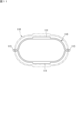
- wire
- shield shell
- connector assembly
- tubular
- Prior art date
- Legal status (The legal status is an assumption and is not a legal conclusion. Google has not performed a legal analysis and makes no representation as to the accuracy of the status listed.)
- Ceased
Links
Images




Classifications
-
- H—ELECTRICITY
- H01—ELECTRIC ELEMENTS
- H01R—ELECTRICALLY-CONDUCTIVE CONNECTIONS; STRUCTURAL ASSOCIATIONS OF A PLURALITY OF MUTUALLY-INSULATED ELECTRICAL CONNECTING ELEMENTS; COUPLING DEVICES; CURRENT COLLECTORS
- H01R13/00—Details of coupling devices of the kinds covered by groups H01R12/70 or H01R24/00 - H01R33/00
- H01R13/58—Means for relieving strain on wire connection, e.g. cord grip, for avoiding loosening of connections between wires and terminals within a coupling device terminating a cable
- H01R13/5804—Means for relieving strain on wire connection, e.g. cord grip, for avoiding loosening of connections between wires and terminals within a coupling device terminating a cable comprising a separate cable clamping part
- H01R13/5812—Means for relieving strain on wire connection, e.g. cord grip, for avoiding loosening of connections between wires and terminals within a coupling device terminating a cable comprising a separate cable clamping part the cable clamping being achieved by mounting the separate part on the housing of the coupling device
-
- H—ELECTRICITY
- H01—ELECTRIC ELEMENTS
- H01R—ELECTRICALLY-CONDUCTIVE CONNECTIONS; STRUCTURAL ASSOCIATIONS OF A PLURALITY OF MUTUALLY-INSULATED ELECTRICAL CONNECTING ELEMENTS; COUPLING DEVICES; CURRENT COLLECTORS
- H01R13/00—Details of coupling devices of the kinds covered by groups H01R12/70 or H01R24/00 - H01R33/00
- H01R13/46—Bases; Cases
- H01R13/52—Dustproof, splashproof, drip-proof, waterproof, or flameproof cases
- H01R13/5205—Sealing means between cable and housing, e.g. grommet
-
- H—ELECTRICITY
- H01—ELECTRIC ELEMENTS
- H01R—ELECTRICALLY-CONDUCTIVE CONNECTIONS; STRUCTURAL ASSOCIATIONS OF A PLURALITY OF MUTUALLY-INSULATED ELECTRICAL CONNECTING ELEMENTS; COUPLING DEVICES; CURRENT COLLECTORS
- H01R13/00—Details of coupling devices of the kinds covered by groups H01R12/70 or H01R24/00 - H01R33/00
- H01R13/648—Protective earth or shield arrangements on coupling devices, e.g. anti-static shielding
- H01R13/658—High frequency shielding arrangements, e.g. against EMI [Electro-Magnetic Interference] or EMP [Electro-Magnetic Pulse]
- H01R13/6591—Specific features or arrangements of connection of shield to conductive members
- H01R13/6592—Specific features or arrangements of connection of shield to conductive members the conductive member being a shielded cable
-
- B—PERFORMING OPERATIONS; TRANSPORTING
- B60—VEHICLES IN GENERAL
- B60R—VEHICLES, VEHICLE FITTINGS, OR VEHICLE PARTS, NOT OTHERWISE PROVIDED FOR
- B60R16/00—Electric or fluid circuits specially adapted for vehicles and not otherwise provided for; Arrangement of elements of electric or fluid circuits specially adapted for vehicles and not otherwise provided for
- B60R16/02—Electric or fluid circuits specially adapted for vehicles and not otherwise provided for; Arrangement of elements of electric or fluid circuits specially adapted for vehicles and not otherwise provided for electric constitutive elements
- B60R16/0207—Wire harnesses
- B60R16/0215—Protecting, fastening and routing means therefor
-
- H—ELECTRICITY
- H01—ELECTRIC ELEMENTS
- H01R—ELECTRICALLY-CONDUCTIVE CONNECTIONS; STRUCTURAL ASSOCIATIONS OF A PLURALITY OF MUTUALLY-INSULATED ELECTRICAL CONNECTING ELEMENTS; COUPLING DEVICES; CURRENT COLLECTORS
- H01R13/00—Details of coupling devices of the kinds covered by groups H01R12/70 or H01R24/00 - H01R33/00
- H01R13/40—Securing contact members in or to a base or case; Insulating of contact members
- H01R13/42—Securing in a demountable manner
- H01R13/422—Securing in resilient one-piece base or case, e.g. by friction; One-piece base or case formed with resilient locking means
- H01R13/4223—Securing in resilient one-piece base or case, e.g. by friction; One-piece base or case formed with resilient locking means comprising integral flexible contact retaining fingers
-
- H—ELECTRICITY
- H01—ELECTRIC ELEMENTS
- H01R—ELECTRICALLY-CONDUCTIVE CONNECTIONS; STRUCTURAL ASSOCIATIONS OF A PLURALITY OF MUTUALLY-INSULATED ELECTRICAL CONNECTING ELEMENTS; COUPLING DEVICES; CURRENT COLLECTORS
- H01R13/00—Details of coupling devices of the kinds covered by groups H01R12/70 or H01R24/00 - H01R33/00
- H01R13/46—Bases; Cases
- H01R13/52—Dustproof, splashproof, drip-proof, waterproof, or flameproof cases
- H01R13/5202—Sealing means between parts of housing or between housing part and a wall, e.g. sealing rings
-
- H—ELECTRICITY
- H01—ELECTRIC ELEMENTS
- H01R—ELECTRICALLY-CONDUCTIVE CONNECTIONS; STRUCTURAL ASSOCIATIONS OF A PLURALITY OF MUTUALLY-INSULATED ELECTRICAL CONNECTING ELEMENTS; COUPLING DEVICES; CURRENT COLLECTORS
- H01R13/00—Details of coupling devices of the kinds covered by groups H01R12/70 or H01R24/00 - H01R33/00
- H01R13/648—Protective earth or shield arrangements on coupling devices, e.g. anti-static shielding
- H01R13/658—High frequency shielding arrangements, e.g. against EMI [Electro-Magnetic Interference] or EMP [Electro-Magnetic Pulse]
- H01R13/6591—Specific features or arrangements of connection of shield to conductive members
- H01R13/65912—Specific features or arrangements of connection of shield to conductive members for shielded multiconductor cable
- H01R13/65914—Connection of shield to additional grounding conductors
-
- H—ELECTRICITY
- H01—ELECTRIC ELEMENTS
- H01R—ELECTRICALLY-CONDUCTIVE CONNECTIONS; STRUCTURAL ASSOCIATIONS OF A PLURALITY OF MUTUALLY-INSULATED ELECTRICAL CONNECTING ELEMENTS; COUPLING DEVICES; CURRENT COLLECTORS
- H01R43/00—Apparatus or processes specially adapted for manufacturing, assembling, maintaining, or repairing of line connectors or current collectors or for joining electric conductors
- H01R43/18—Apparatus or processes specially adapted for manufacturing, assembling, maintaining, or repairing of line connectors or current collectors or for joining electric conductors for manufacturing bases or cases for contact members
Definitions
- a wire harness is used to connect multiple in-vehicle devices.
- the wire harness is electrically connected to the in-vehicle device via a connector.
- a connector is disclosed in Patent Document 1.
- a connector assembly includes a connector housing that holds a terminal connected to an end of an electric wire, a tubular shield shell that surrounds the connector housing, and a shield shell that is attached to the shield shell and extends from the connector housing.
- a tubular braided wire surrounding the electric wire extending in one direction; a tubular rubber boot attached to the shield shell and surrounding the braided wire; a first tightening member for tightening the rubber boot to the shield shell; to the shield shell, wherein the shield shell includes a tubular boot attachment portion for attaching the rubber boot, a tubular wire attachment portion for attaching the braided wire, wherein the wire attachment portion is provided closer to the first direction than the boot attachment portion, and the rubber boot includes a tubular boot body and a boot body protruding radially inward from the boot body.
- the tubular boot attachment portion has, on its outer peripheral side, a tubular seal surface with which the seal portion contacts, and a portion of the first direction side of the seal surface. and a first project
- FIG. 1 is a perspective view showing the connector assembly of this embodiment.
- 2 is an exploded perspective view of the connector assembly shown in FIG. 1;
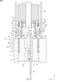
- FIG. 3 is a cross-sectional view of the connector assembly shown in FIG. 1;
- FIG. FIG. 4 is a cross-sectional view showing part of the shield shell.
- FIG. 5 is a perspective view of a first tightening member;
- FIG. 6 is a perspective view of a second tightening member;
- FIG. 7 is a schematic diagram of a boot attachment portion and a wire attachment portion.
- FIG. 8 is a cross-sectional view showing part of the connector assembly.
- FIG. 9 is a cross-sectional view of the portion where the braided wire is attached by the second tightening member.
- FIG. 10 is a cross-sectional view of a conventional connector assembly.
- FIG. 11 is an explanatory diagram of a conventional crimping ring.
- a connector includes a braided wire that encloses wires extending from its body and a tubular rubber boot that encloses the braided wire, and can also be called a connector assembly.
- FIG. 10 is a cross-sectional view of a conventional connector assembly 100. As shown in FIG. The connector assembly 100 includes a connector housing 101, a cylindrical shield shell 102 surrounding the connector housing 101, a braided wire 103 attached to the shield shell 102, and a rubber boot 104 attached to the shield shell 102 and surrounding the braided wire 103.
- Connector housing 101 holds terminal 106 connected to end 105 a of electric wire 105 .
- the electric wire 105 is provided extending from the connector housing 101 in the first direction (from left to right in FIG. 10).
- the braided wire 103 is tubular to surround the wire 105 thereof.
- the braided wire 103 is fixed to a portion 102a of the shield shell 102 by a crimping ring 110.
- the rubber boot 104 has a tubular boot body 107 and an annular seal portion 108 .
- the shield shell 102 has a cylindrical sealing surface 109 with which the sealing portion 108 contacts on its outer peripheral side.
- the crimping ring 110 is made of a plastically deformable metal member.
- a crimping ring 110 is provided with a plate portion 111 for preventing the rubber boot 104 from coming off.
- the seal portion 108 comes into contact with the plate portion 111 of the crimping ring 110 .
- the crimping ring 110 is a member for tightening and fixing the braided wire 103 to the shield shell 102 . Therefore, when assembling the connector assembly 100, the crimping ring 110 is plastically deformed in a direction of reducing the diameter.
- FIG. 11 is an explanatory diagram of the crimping ring 110, in which the state after diameter reduction is indicated by a solid line, and the state before diameter reduction is indicated by a two-dot chain line. When the diameter of the crimping ring 110 is reduced, an extra length is generated as projections 113 at two locations in the circumferential direction.
- the protrusion 113 becomes larger radially outward. Although the size of the protrusion 113 is approximately constant, variations may occur. Considering the variation, the rubber boot 104 (see FIG. 10) is designed to be large as a whole including a margin so as not to come into contact with the protrusion 113 . Therefore, there is a problem that the connector assembly 101 expands in the radial direction.
- the connector assembly of this embodiment includes a connector housing that holds terminals connected to ends of electric wires, a tubular shield shell that surrounds the connector housing, and a shield shell that is attached to the shield shell and extends from the connector housing.
- tubular braided wire surrounding the electric wire extending in one direction; a tubular rubber boot attached to the shield shell and surrounding the braided wire; a first tightening member for tightening the rubber boot to the shield shell; to the shield shell, wherein the shield shell includes a tubular boot attachment portion for attaching the rubber boot, a tubular wire attachment portion for attaching the braided wire, wherein the wire attachment portion is provided closer to the first direction than the boot attachment portion, and the rubber boot includes a tubular boot body and a boot body protruding radially inward from the boot body.
- the tubular boot attachment portion has, on its outer peripheral side, a tubular seal surface with which the seal portion contacts, and a portion of the first direction side of the seal surface. and a first projecting portion projecting radially outward from the portion.
- the connector assembly of this embodiment it is possible to prevent the rubber boot from coming off in the first direction by the first projecting portion.
- the first protrusion is provided on the shield shell and can be designed so that the rubber boot does not interfere with the first protrusion. In other words, it is no longer necessary to design a large rubber boot including a margin as in the conventional case, and it is possible to reduce the size of the connector assembly in the radial direction.
- the tubular wire attachment portion has, on its outer peripheral side, a tubular electrical connection surface that is electrically connected to the braided wire, and the wire attachment portion is located on the electrical connection surface.
- a second projecting portion projecting radially outward from a portion of the first direction side, and a tip of the second projecting portion is located radially inward of a tip of the first projecting portion. .
- the second projecting portion can prevent the braided wire from coming off in the first direction.
- the wire attachment portion as a whole is radially smaller than the boot attachment portion. As a result, the boot body can be made smaller in the radial direction, which contributes to miniaturization of the connector assembly.
- the tip of the second projecting portion is located radially inside the sealing surface. In this case, the wire attachment portion becomes even smaller in the radial direction.
- the second projecting portion is provided over the entire circumference of the wire attachment portion. In this case, the function of preventing the braided wire from falling off is enhanced.
- the first projecting portion is provided over the entire circumference of the boot mounting portion. In this case, the fall-off prevention function of the rubber boot is enhanced.
- the second tightening member has a band-shaped portion provided along the outer circumference of the tubular braided wire, and a tightening portion provided at one end of the band-shaped portion,
- the tightening portion has a locking portion that allows the other end of the band-shaped portion to pass therethrough and prevents the inserted band-shaped portion from moving in the direction opposite to the insertion direction.
- the boot body includes a cylindrical portion having a smooth inner surface, and a portion of the boot body provided in a circumferential direction of which the inner surface is radially wider than the cylindrical portion. and an accommodating portion located outside the clamping portion, wherein the tightening portion is accommodated in the accommodating portion.
- an accommodating portion for accommodating the tightening portion of the second tightening member may be provided in a portion of the boot body in the circumferential direction, and the entire boot body does not have to be unnecessarily large.
- the boot attachment portion has, on its inner peripheral side, a first inclined surface that decreases in diameter in the first direction
- the wire attachment portion has, on its inner peripheral side, the second It has a second inclined surface that expands in diameter in one direction.
- the second inclined surface of the wire attachment portion is reduced in diameter in the first direction, it is possible to reduce the radial dimension of the boot attachment portion and the wire attachment portion as a whole.
- a connector assembly 10 of the present embodiment shown in FIG. 1 is used as a conductive path for electrically connecting a plurality of electrical devices.
- electric devices such as an inverter and a battery are installed in a vehicle such as an electric vehicle or a hybrid vehicle. Electrical devices (in-vehicle devices) are connected via conductive paths for power supply.
- the conductive path includes a wire harness (electric wire) and a connector connected to an end of the wire harness.
- the connector assembly 10 of this embodiment is used as the connector.
- FIG. 1 is a perspective view showing a connector assembly 10 of this embodiment.
- FIG. 2 is an exploded perspective view of connector assembly 10 shown in FIG.
- FIG. 3 is a cross-sectional view of connector assembly 10 shown in FIG.
- the connector assembly 10 is attached to a portion of the case 7 (see FIG. 3) of the electrical equipment.
- Two electric wires 8 are connected to the connector assembly 10 . Power is supplied to the electrical device through the electrical wire 8 and the connector assembly 10 .
- the connector assembly 10 includes a connector housing 11, a shield shell 12, a braided wire 13, a rubber boot 14, a first tightening member 16 and a second tightening member 17.
- Connector assembly 10 (see FIG. 3) further comprises retainer 28 , annular sealing member 29 , first rubber ring 33 , second rubber ring 34 and third rubber ring 35 .
- the connector housing 11 holds the terminal 18 connected to the end 21 of the electric wire 8 .
- the terminal 18 is a metal member elongated in one direction.
- One end 18a of the terminal 18 is electrically connected to a mating connector (not shown) of the electrical equipment.
- the other end 18b of the terminal 18 is electrically connected to the electric wire 8.
- the electric wire 8 is provided extending from the connector housing 11 in the first direction (direction from left to right in FIG. 3).
- the orientation in the connector assembly 10 of the present disclosure will now be defined.
- the direction in which the electric wire 8 extends from the connector housing 11 (the first direction) is defined as the "front-rear direction”.
- the one end portion 18a side of the terminal 18 is “front”, and the direction side (right side in FIG. 3) in which the electric wire 8 extends is “rear”.
- Two electric wires 8 are provided side by side (see FIGS. 1 and 2).
- the direction in which the two electric wires 8 are arranged is defined as the "horizontal direction”.
- a direction perpendicular to both the front-rear direction and the left-right direction is defined as the “vertical direction”.
- XYZ orthogonal coordinates are shown in each figure.
- the X direction is the horizontal direction
- the Y direction is the front-rear direction (direction from front to back)
- the Z direction is the vertical direction (direction from bottom to top).
- One terminal 18 is connected to one electric wire 8 .
- two terminals 18 are provided side by side in the left-right direction.
- the connector housing 11 and the shield shell 12 have an oval columnar or cylindrical shape as a whole. Therefore, while the front-rear direction can be called the "axial direction”, the left-right direction and the vertical direction perpendicular thereto can be collectively called the "radial direction”.
- the connector housing 11 is made of resin.
- the connector housing 11 has a holding portion 31 and a shell attachment portion 32 .
- the holding portion 31 has an oval columnar shape with the left-right direction as the major axis direction.
- a space 31a for accommodating the terminal 18 is provided inside the holding portion 31 (see FIG. 3).
- the shell attachment portion 32 has a substantially elliptical tubular shape with the left-right direction as the major axis direction.
- the holding portion 31 is a portion that accommodates and holds the terminal 18 .
- Terminal 18 is fixed to holding portion 31 .
- the shell attachment portion 32 extends rearward (in the Y direction) from the holding portion 31 and has a shape smaller than the holding portion 31 in the vertical direction and the horizontal direction (radial direction).
- the shell mounting portion 32 has a first tubular portion 37 on the front side and a second tubular portion 38 on the rear side.
- a mounting groove 39 for mounting the third rubber ring 35 is provided on the outer circumference of the first cylindrical portion 37 .
- the second tubular portion 38 has a shape that is smaller than the first tubular portion 37 in the vertical direction and the lateral direction (radial direction).
- the seal member 29 is a ring-shaped rubber member, which is in close contact with the outer peripheral surface of the electric wire 8 and the inner peripheral surface of the shell attachment portion 32 (second cylindrical portion 38).
- the sealing member 29 prevents foreign matter such as water from entering between the wire 8 and the connector housing 11 .
- the retainer 28 is a member made of resin having a hole through which the two electric wires 8 pass. The retainer 28 is attached to the rear portion of the shell attachment portion 32 (second tubular portion 38) and prevents the seal member 29 from falling off backward.
- the first rubber ring 33 and the second rubber ring 34 are annular rubber members.
- the first rubber ring 33 and the second rubber ring 34 are attached to the outer peripheral surface of the holding portion 31 side by side in the front-rear direction.
- the first rubber ring 33 and the second rubber ring 34 are in close contact with the mounting hole 7a of the case 7 of the electrical equipment.
- the first rubber ring 33 and the second rubber ring 34 prevent foreign matter such as water from entering between the connector housing 11 and the case 7 .
- the third rubber ring 35 is an annular rubber member.
- the third rubber ring 35 is attached to the outer peripheral surface of the shell attachment portion 32 (first tubular portion 37).
- the third rubber ring 35 is in close contact with the inner peripheral surface of the shield shell 12 (boot mounting portion 19 described later).
- the third rubber ring 35 prevents foreign matter such as water from entering between the connector housing 11 and the shield shell 12 .
- the shield shell 12 has a cylindrical main body 30 and surrounds the shell attachment portion 32 of the connector housing 11 .
- the shield shell 12 has a cylindrical main body 30 and a flange portion 40 attached to the case 7 .
- the shield shell 12 is made of metal.
- Shield shell 12 is a casting.
- the case 7 is made of aluminum, and the shield shell 12 is also made of aluminum to prevent electrolytic corrosion due to contact between dissimilar metals.
- FIG. 4 is a sectional view showing part of the shield shell 12. As shown in FIG.
- the shield shell 12 has a tubular boot attachment portion 19 for attaching the rubber boot 14 and a tubular wire attachment portion 20 for attaching the braided wire 13 .
- the wire attachment portion 20 is provided on the first direction side where the electric wire 8 extends from the connector housing 11 from the boot attachment portion 19 . That is, the wire attachment portion 20 is provided behind the boot attachment portion 19 .
- a flange portion 40 is provided on the front side of the boot mounting portion 19 .
- the boot mounting portion 19 and the wire mounting portion 20 have an oval cylindrical shape with the left-right direction as the major axis direction (see FIG. 2).
- the wire attachment portion 20 has a shape that is smaller than the boot attachment portion 19 in both the outer and inner circumferences in the vertical direction and the lateral direction.
- a third rubber ring 35 contacts the inner peripheral surface of the boot mounting portion 19 .
- the shield shell 12 is a cast product, and the boot mounting portion 19, the wire mounting portion 20, and the flange portion 40 are integrally formed.
- the braided wire 13 is a conductor formed by braiding metallic (for example, copper) strands.
- the braided wire 13 has a long tubular shape provided along the electric wire 8 and surrounds the electric wire 8 .
- the braided wire 13 is attached to the wire attachment portion 20 of the shield shell 12 and electrically connected to the shield shell 12 .
- the braided wire 13 covers the outer peripheral surface of the wire attachment portion 20 .
- the braided wire 13 is tightened and fixed to the wire attachment portion 20 by a second tightening member 17 which will be described later.
- the braided wire 13 is attached to the shield shell 12 and surrounds the wire 8 extending from the connector housing 11 in the first direction.
- Braided wire 13 functions as a shield for wire 8 together with shield shell 12 .
- the rubber boot 14 is made of rubber.
- the rubber boot 14 has a long tubular shape provided along the braided wire 13 and surrounds the braided wire 13 . 1 and 2 show a state in which the rubber boot 14 is cut halfway.
- the rubber boot 14 is attached to the boot attachment portion 19 of the shield shell 12 .
- the rubber boot 14 covers the outer peripheral surface of the boot mounting portion 19 .
- the rubber boot 14 is tightened and fixed to the boot mounting portion 19 by a first tightening member 16 which will be described later.
- the rubber boot 14 is attached to the shield shell 12 and surrounds the braided wire 13 .
- a rubber boot 14 is provided along the longitudinal direction of the electric wire 8 .
- the rubber boot 14 has a tubular boot body 22 surrounding the braided wire 13 and an annular seal portion 23 (see FIG. 4).
- the seal portion 23 is provided so as to protrude radially inward of the boot body 22 from the front end portion 22 a of the boot body 22 .
- the seal portion 23 has a plurality of annular convex lip portions 42 , and the lip portions 42 contact the seal surface 24 .
- An annular groove 41 is formed on the outer periphery of the end portion 22a of the boot body 22. As shown in FIG. A first fastening member 16 , which will be described later, is attached to the concave groove 41 .
- the rubber boot 14 is tightened and fixed to the boot mounting portion 19 by the first tightening member 16 .
- the first tightening member 16 is a member that tightens the rubber boot 14 to the shield shell 12 .
- FIG. 5 is a perspective view of the first tightening member 16.
- the first tightening member 16 has an elongate strip-shaped portion 44 and a tightening portion 45 provided at one end 44 a of the strip-shaped portion 44 .
- the tightening portion 45 has a locking portion 46 .
- the locking portion 46 allows the other end 44b of the band-shaped portion 44 to pass therethrough and prevents the inserted band-shaped portion 44 from moving in the direction opposite to the insertion direction.
- the locking portion 46 has a claw, and the claw engages with a part of the band-shaped portion 44 to prevent the diameter of the loop-shaped band-shaped portion 44 from being expanded.
- a band-shaped portion 44 is provided along the outer circumference of the rubber boot 14 fitted on the boot mounting portion 19 (see FIG. 4).
- the other end 44b of the band-shaped portion 44 is inserted through the lock portion 46.
- the belt-shaped portion 44 tightens the rubber boot 14 to the boot mounting portion 19 .
- the first tightening member 16 has an annular shape when the rubber boot 14 is tightened.
- the first tightening member 16 may be made of metal such as stainless steel, but is made of resin in this embodiment.
- the second tightening member 17 is a member that tightens the braided wire 13 to the shield shell 12 .
- 6 is a perspective view of the second tightening member 17.
- the second tightening member 17 has an elongate strip-shaped portion 47 and a tightening portion 48 provided at one end 47 a of the strip-shaped portion 47 .
- the tightening portion 48 has a locking portion 49 .
- the locking portion 49 allows the other end 47b of the band-shaped portion 47 to pass therethrough and prevents the inserted band-shaped portion 47 from moving in the direction opposite to the insertion direction.
- the locking portion 49 has a claw, and the claw engages with a part of the band-shaped portion 47 to prevent the diameter of the loop-shaped band-shaped portion 47 from being expanded.
- a band-shaped portion 47 is provided along the outer circumference of the tubular braided wire 13 provided on the outer circumference of the wire attachment portion 20 (see FIG. 4).
- the other end 47b of the band-shaped portion 47 is inserted through the lock portion 49.
- the braided wire 13 is fastened to the wire attachment portion 20 by the belt-like portion 47 .
- the second tightening member 17 has a ring shape when the braided wire 13 is tightened.
- the second tightening member 17 may be made of resin, but is made of metal such as stainless steel. Since the second tightening member 17 is made of metal, it is difficult for the second tightening member 17 to be deformed by heat, and it is difficult for the tightening force to be released.
- the boot mounting portion 19 will be further described with reference to FIGS. 2 and 4.
- FIG. The boot mounting portion 19 has a tubular shape and has a seal surface 24 and a first projecting portion 25 on its outer peripheral side.
- the seal surface 24 is a cylindrical surface, and the seal portion 23 of the rubber boot 14 contacts.
- the first tightening member 16 contacts the seal portion 23 while being pressed against the seal surface 24 .
- the first protruding portion 25 protrudes radially outward of the boot mounting portion 19 from a part (end portion) on the rear side of the sealing surface 24 .
- a tip 25 a of the first projecting portion 25 is positioned radially outward of the sealing surface 24 .
- the first projecting portion 25 is provided over the entire circumference of the boot mounting portion 19 .
- the boot attachment portion 19 further has an annular portion 51 .
- the annular portion 51 is provided so as to protrude radially outward from the boot mounting portion 19 from a front portion (end portion) of the seal surface 24 .
- the flange portions 40 are connected to both lateral side portions of the annular portion 51 .
- the boot mounting portion 19 has a contact surface on its inner peripheral side with which the third rubber ring 35 contacts.
- the seal surface 24 has a linear shape parallel to the straight line in the front-rear direction.
- the inner peripheral surface 55 of the boot mounting portion 19 has a linear shape that is inclined with respect to a straight line in the front-rear direction.
- the boot mounting portion 19 has a first inclined surface 53 on its inner peripheral surface 55, the diameter of which decreases from the front to the rear. For this reason, the boot mounting portion 19 is formed such that its radial thickness is reduced from the rear to the front.
- the first inclined surface 53 is the contact surface of the third rubber ring 35 .
- the wire attachment portion 20 will be further described with reference to FIGS. 2 and 4.
- FIG. The wire attachment portion 20 has a tubular shape and has an electrical connection surface 26 on its outer peripheral side.
- the electrical connection surface 26 is a cylindrical surface and electrically connected to the braided wire 13 .
- a portion of the braided wire 13 is brought into clamped contact with the electrical connection surface 26 by the second clamping member 17 .
- the wire attachment portion 20 has a shape smaller than the boot attachment portion 19 in the vertical and horizontal directions. Therefore, the electrical connection surface 26 is provided radially inward of the sealing surface 24 .
- the wire attachment portion 20 has a second projecting portion 27 on its outer peripheral side.
- the second protruding portion 27 protrudes radially outward from the wire attachment portion 20 from a rear portion (end portion) of the electrical connection surface 26 .
- a tip 27 a of the second projecting portion 27 is positioned radially outward of the electrical connection surface 26 .
- the second projecting portion 27 is provided over the entire circumference of the wire attachment portion 20 . As shown in FIG. 4 , the tip 27a of the second projecting portion 27 is located radially inside the tip 25a of the first projecting portion 25 . Furthermore, in the present embodiment, the tip 27a of the second projecting portion 27 is located radially inside the sealing surface 24 .
- the inner peripheral surface (first inner peripheral surface 54) of the wire attachment portion 20 is smaller than the inner peripheral surface (second inner peripheral surface 55) of the boot attachment portion 19 in the vertical direction and the lateral direction (radial direction). have. Therefore, an annular wall surface 56 is provided between the first inner peripheral surface 54 and the second inner peripheral surface 55 (see FIG. 4).
- the wall surface 56 is an annular surface facing forward.
- the electrical connection surface 26 has a linear shape parallel to the straight line in the front-rear direction.
- the inner peripheral surface 54 of the wire attachment portion 20 has a linear shape that is inclined with respect to the straight line in the front-rear direction. That is, the wire attachment portion 20 has a second inclined surface 58 on the inner peripheral surface 54 thereof, the diameter of which increases from the front to the rear. For this reason, the wire attachment portion 20 is configured such that its radial thickness decreases from the front to the rear.
- FIG. 7 is a schematic diagram of the boot attachment portion 19 and the wire attachment portion 20.
- FIG. 7A on the left side, as described above, the boot attachment portion 19 has the first inclined surface 53 on its inner peripheral side, the diameter of which decreases toward the rear.
- the wire attachment portion 20 has, on its inner peripheral side, a second inclined surface 58 that expands in diameter toward the rear.
- FIG. 7 shows the inclination angles of the inner peripheral sides of the wire attachment portion 20 and the boot attachment portion 19 larger than they actually are.
- the shield shell 12 is manufactured by casting.
- the split mold for forming the inner peripheral surface of the shield shell 12 moves in the axial direction.
- the shield shell 12 having the first slanted surface 53 and the second slanted surface 58 facilitates demolding.
- FIG. 7 shows a modified example.
- the boot mounting portion 19 has a first inclined surface 53 on its inner peripheral side, the diameter of which decreases in the rearward direction. This point is the same as the present embodiment shown in (A) on the left side of FIG.
- the wire attachment portion 20 has, on its inner peripheral side, a second inclined surface 58 whose diameter decreases toward the rear. That is, the direction of inclination of the inner peripheral side of the wire attachment portion 20 is opposite between the present embodiment and the modified example.
- the radial dimension (inner diameter) of the first tubular portion 37 is the same between the present embodiment shown in FIG. 7A and the modification shown in FIG. 7B.
- the inner peripheral surface of the shield shell 12 as a whole increases radially from the rear side to the front side. That is, starting from the rear end 12e of the shield shell 12, the diameter increases in the radial direction from the rear end 12e toward the front end 12f. Therefore, the radial dimension from the rear end 12e to the front end 12f is increased. As a result, the shield shell 12 becomes thicker in the radial direction.
- the inner peripheral surface of the shield shell 12 starts from the central portion 12c in the front-rear direction and extends radially forward from the central portion 12c. , and radially increases rearward from the central portion 12c. Therefore, the radial dimension from the central portion 12c, which is the starting point, to the front end 12f is reduced.
- the shield shell 12 becomes thin in the radial direction, making it possible to make the connector assembly 10 including the rubber boot 14 small in the radial direction.
- a dimensional difference in the radial direction of the outer surface 14a of the rubber boot 14 between the modified example and the present embodiment is shown as "Q" in FIG.
- the dimension Q is radially smaller than in the modified example.
- the connector assembly 10 of the present embodiment includes the connector housing 11, the cylindrical shield shell 12 surrounding the connector housing 11, and the shield shell 12 attached to the connector housing 11, as shown in FIGS. a tubular braided wire 13 attached to the shield shell 12; a tubular rubber boot 14 attached to the shield shell 12; a first tightening member 16 for tightening the rubber boot 14 to the shield shell 12; and a second tightening member 17 for tightening.
- Connector housing 11 holds terminals 18 that are connected to ends 21 of wires 8 .
- Braided wire 13 surrounds wire 8 extending rearward from connector housing 11 .
- a rubber boot 14 surrounds the braided wire 13 .
- the shield shell 12 has a tubular boot attachment portion 19 for attaching the rubber boot 14 and a tubular wire attachment portion 20 for attaching the braided wire 13 .
- the wire attachment portion 20 is provided behind the boot attachment portion 19 .
- the rubber boot 14 has a tubular boot body 22 and an annular seal portion 23 .
- the seal portion 23 is provided so as to protrude radially inward from the boot body 22 .
- the tubular boot mounting portion 19 has, on its outer peripheral side, a tubular sealing surface 24 with which the sealing portion 23 contacts, and a first projecting portion 25 .
- the first protruding portion 25 protrudes radially outward from a portion of the rear side of the sealing surface 24 .
- the first projecting portion 25 can prevent the rubber boot 14 from falling off to the rear.
- the first projecting portion 25 is provided on the shield shell 12 and can be designed so that the rubber boot 14 does not interfere with the first projecting portion 25 . In other words, it is not necessary to design the rubber boot 14 to be large including a margin as in the conventional art. As a result, it is possible to make the connector assembly 10 radially compact.
- the shield shell 12 has a tubular wire attachment portion 20 .
- the cylindrical wire attachment portion 20 has a cylindrical electrical connection surface 26 electrically connected to the braided wire 13 on its outer peripheral side.
- the electrical connection surface 26 is provided radially inside the seal surface 24 .
- the wire attachment portion 20 is radially smaller than the boot attachment portion 19 . Therefore, the boot body 22 surrounding the braided wire 13 attached to the wire attachment portion 20 can be made smaller in the radial direction. As a result, it is possible to make the connector assembly 10 radially compact.
- FIG. 8 is a cross-sectional view showing part of the connector assembly 10.
- FIG. 8 (A) on the left and center (B) show modified examples 2 and 3, and (C) on the right shows this embodiment.
- the third rubber ring 35 is not provided in the modified example 2 shown in (A).
- the sealing function to prevent water from entering is low.
- the third rubber ring 35 is provided to enhance the sealing function, but the radial dimension is increased compared to Modification 2 shown in (A). Therefore, in the present embodiment shown in (C), even if the third rubber ring 35 is provided, the wire attachment portion 20 is radially smaller than the boot attachment portion 19 . Therefore, in this embodiment, it is possible to reduce the size of the connector assembly 10 in the radial direction.
- the wire attachment portion 20 further has a second projecting portion 27 projecting radially outward from a portion of the rear side of the electrical connection surface 26 .
- the second projecting portion 27 can prevent the braided wire 13 from falling off to the rear.
- the tip 27a of the second projecting portion 27 is located radially inside the tip 25a of the first projecting portion 25 . Therefore, the wire attachment portion 20 as a whole is radially smaller than the boot attachment portion 19 .
- the tip 27 a of the second projecting portion 27 is located radially inside the sealing surface 24 . Therefore, the wire attachment portion 20 becomes even smaller in the radial direction.
- the boot body 22 can be made smaller in the radial direction, which contributes to miniaturization of the connector assembly 10 .
- the first projecting portion 25 is provided over the entire circumference of the boot mounting portion 19 . Therefore, the function of preventing the rubber boot 14 from coming off is enhanced.
- the second projecting portion 27 is provided over the entire circumference of the wire attachment portion 20 . Therefore, the function of preventing the braided wire 13 from coming off is enhanced.
- FIG. 9 is a cross-sectional view of the portion where the braided wire 13 is attached by the second tightening member 17.
- FIG. FIG. 9 shows a cross section perpendicular to the front-rear direction.
- the second tightening member 17 has an elongate strip-shaped portion 47 and a tightening portion 48 provided at one end 47a of the strip-shaped portion 47 .
- the tightening portion 48 protrudes radially outward from the strip portion 47 .
- a housing portion 63 for housing the tightening portion 48 is provided in a part of the boot body 22 in the circumferential direction. ing.
- the boot body 22 has a tubular portion 61 having a smooth inner surface 62 and a housing portion 63 provided in a portion of the boot body 22 in the circumferential direction.
- the smooth inner surface 62 has an oval tubular shape with the left-right direction as the major axis direction.
- An inner surface 64 of the accommodating portion 63 is located radially outside the inner surface 62 of the cylindrical portion 61 . In other words, the inner surface of a part of the boot body 42 (accommodating portion 63) bulges outward in the radial direction.
- the entire accommodating portion 63 bulges outward in the radial direction.
- the tightening portion 48 of the second tightening member 17 is accommodated in the accommodation portion 63 . Therefore, the accommodation portion 63 for accommodating the tightening portion 48 of the second tightening member 17 may be provided in a part of the boot body 22 in the circumferential direction, and the boot body 22 as a whole does not need to be enlarged unnecessarily. . As described above, it is possible to reduce the size of the connector assembly 10 in the radial direction.
- first tightening member 16 and the second tightening member 17 may be made of materials other than those described above, and may be of forms other than those shown in the drawings.
Landscapes
- Connector Housings Or Holding Contact Members (AREA)
- Details Of Connecting Devices For Male And Female Coupling (AREA)
Priority Applications (4)
| Application Number | Priority Date | Filing Date | Title |
|---|---|---|---|
| CN202280088409.6A CN118591947A (zh) | 2022-01-17 | 2022-12-09 | 连接器组件 |
| JP2023573910A JP7757430B2 (ja) | 2022-01-17 | 2022-12-09 | コネクタアセンブリ |
| US18/729,808 US20250167484A1 (en) | 2022-01-17 | 2022-12-09 | Connector assembly |
| EP22919292.7A EP4468529A4 (en) | 2022-01-17 | 2022-12-09 | Connector assembly |
Applications Claiming Priority (2)
| Application Number | Priority Date | Filing Date | Title |
|---|---|---|---|
| JP2022-004967 | 2022-01-17 | ||
| JP2022004967 | 2022-01-17 |
Publications (1)
| Publication Number | Publication Date |
|---|---|
| WO2023136007A1 true WO2023136007A1 (ja) | 2023-07-20 |
Family
ID=87278859
Family Applications (1)
| Application Number | Title | Priority Date | Filing Date |
|---|---|---|---|
| PCT/JP2022/045555 Ceased WO2023136007A1 (ja) | 2022-01-17 | 2022-12-09 | コネクタアセンブリ |
Country Status (5)
| Country | Link |
|---|---|
| US (1) | US20250167484A1 (https=) |
| EP (1) | EP4468529A4 (https=) |
| JP (1) | JP7757430B2 (https=) |
| CN (1) | CN118591947A (https=) |
| WO (1) | WO2023136007A1 (https=) |
Citations (4)
| Publication number | Priority date | Publication date | Assignee | Title |
|---|---|---|---|---|
| JP2011044354A (ja) * | 2009-08-21 | 2011-03-03 | Sumitomo Wiring Syst Ltd | シールドコネクタ及びワイヤハーネス |
| JP2011086396A (ja) * | 2009-10-13 | 2011-04-28 | Autonetworks Technologies Ltd | コネクタ用ゴムブーツ及びコネクタ |
| WO2014045634A1 (ja) * | 2012-09-18 | 2014-03-27 | 住友電装株式会社 | グロメット及びグロメット付き取付部材 |
| JP2021012847A (ja) | 2019-07-09 | 2021-02-04 | 住友電装株式会社 | コネクタ |
Family Cites Families (1)
| Publication number | Priority date | Publication date | Assignee | Title |
|---|---|---|---|---|
| JP5917013B2 (ja) * | 2011-04-19 | 2016-05-11 | 住友電装株式会社 | シールドコネクタ |
-
2022
- 2022-12-09 CN CN202280088409.6A patent/CN118591947A/zh active Pending
- 2022-12-09 US US18/729,808 patent/US20250167484A1/en active Pending
- 2022-12-09 WO PCT/JP2022/045555 patent/WO2023136007A1/ja not_active Ceased
- 2022-12-09 JP JP2023573910A patent/JP7757430B2/ja active Active
- 2022-12-09 EP EP22919292.7A patent/EP4468529A4/en not_active Withdrawn
Patent Citations (4)
| Publication number | Priority date | Publication date | Assignee | Title |
|---|---|---|---|---|
| JP2011044354A (ja) * | 2009-08-21 | 2011-03-03 | Sumitomo Wiring Syst Ltd | シールドコネクタ及びワイヤハーネス |
| JP2011086396A (ja) * | 2009-10-13 | 2011-04-28 | Autonetworks Technologies Ltd | コネクタ用ゴムブーツ及びコネクタ |
| WO2014045634A1 (ja) * | 2012-09-18 | 2014-03-27 | 住友電装株式会社 | グロメット及びグロメット付き取付部材 |
| JP2021012847A (ja) | 2019-07-09 | 2021-02-04 | 住友電装株式会社 | コネクタ |
Non-Patent Citations (1)
| Title |
|---|
| See also references of EP4468529A4 |
Also Published As
| Publication number | Publication date |
|---|---|
| JPWO2023136007A1 (https=) | 2023-07-20 |
| JP7757430B2 (ja) | 2025-10-21 |
| EP4468529A4 (en) | 2025-04-16 |
| CN118591947A (zh) | 2024-09-03 |
| EP4468529A1 (en) | 2024-11-27 |
| US20250167484A1 (en) | 2025-05-22 |
Similar Documents
| Publication | Publication Date | Title |
|---|---|---|
| JP5768618B2 (ja) | ワイヤハーネスの端末防水構造 | |
| JP7128237B2 (ja) | 防水コネクタ | |
| JP5772742B2 (ja) | 電線保持装置及びワイヤハーネス | |
| JP5837739B2 (ja) | 編組線の接続構造 | |
| JP6550095B2 (ja) | 樹脂入りパッキン及び防水コネクタ | |
| CN111463621B (zh) | 防水密封垫、防水连接器和线束 | |
| CN109428233B (zh) | 直接安装于装置的屏蔽连接器 | |
| JP4550305B2 (ja) | 機器接続用シールドコネクタ | |
| JP5488387B2 (ja) | 電線導出構造およびシールドブラケット | |
| JP2008288021A (ja) | シールドコネクタ | |
| US20250329955A1 (en) | Connector | |
| JP7430738B2 (ja) | ワイヤハーネス | |
| WO2023136007A1 (ja) | コネクタアセンブリ | |
| JP4278846B2 (ja) | 機器接続用シールドコネクタ | |
| US12355181B2 (en) | Fitting device | |
| JP3947092B2 (ja) | 機器用コネクタ | |
| JP7690348B2 (ja) | 防水コネクタ | |
| JP5772386B2 (ja) | シールド部材及びシールド導電体 | |
| US7347730B2 (en) | Grommet | |
| JP2007087874A (ja) | シールドコネクタ | |
| JP7399792B2 (ja) | シールドコネクタ | |
| JP4369602B2 (ja) | 機器接続用シールドコネクタ | |
| JP6415152B2 (ja) | 防水コネクタ | |
| JP7473513B2 (ja) | コネクタ | |
| US20240396257A1 (en) | Waterproof connector |
Legal Events
| Date | Code | Title | Description |
|---|---|---|---|
| 121 | Ep: the epo has been informed by wipo that ep was designated in this application |
Ref document number: 22919292 Country of ref document: EP Kind code of ref document: A1 |
|
| ENP | Entry into the national phase |
Ref document number: 2023573910 Country of ref document: JP Kind code of ref document: A |
|
| WWE | Wipo information: entry into national phase |
Ref document number: 202280088409.6 Country of ref document: CN |
|
| WWE | Wipo information: entry into national phase |
Ref document number: 18729808 Country of ref document: US |
|
| WWE | Wipo information: entry into national phase |
Ref document number: 2022919292 Country of ref document: EP |
|
| NENP | Non-entry into the national phase |
Ref country code: DE |
|
| ENP | Entry into the national phase |
Ref document number: 2022919292 Country of ref document: EP Effective date: 20240819 |
|
| WWP | Wipo information: published in national office |
Ref document number: 18729808 Country of ref document: US |
|
| WWW | Wipo information: withdrawn in national office |
Ref document number: 2022919292 Country of ref document: EP |