WO2023132322A1 - Cutting insert, cutting tool, and method for manufacturing cut workpiece - Google Patents
Cutting insert, cutting tool, and method for manufacturing cut workpiece Download PDFInfo
- Publication number
- WO2023132322A1 WO2023132322A1 PCT/JP2022/048586 JP2022048586W WO2023132322A1 WO 2023132322 A1 WO2023132322 A1 WO 2023132322A1 JP 2022048586 W JP2022048586 W JP 2022048586W WO 2023132322 A1 WO2023132322 A1 WO 2023132322A1
- Authority
- WO
- WIPO (PCT)
- Prior art keywords
- rising
- cutting
- rising surface
- corner
- chips
- Prior art date
Links
Images


Classifications
-
- B—PERFORMING OPERATIONS; TRANSPORTING
- B23—MACHINE TOOLS; METAL-WORKING NOT OTHERWISE PROVIDED FOR
- B23B—TURNING; BORING
- B23B27/00—Tools for turning or boring machines; Tools of a similar kind in general; Accessories therefor
- B23B27/14—Cutting tools of which the bits or tips or cutting inserts are of special material
Definitions
- the present disclosure relates to a cutting insert, a cutting tool, and a method of manufacturing a cut product used for cutting a work material.
- the cutting of the work material includes, for example, turning and milling.
- Turning includes, for example, outer diameter machining, inner diameter machining, grooving and parting off.
- Patent Document 1 discusses a cutting tool used for cutting a work material made of a metal material or the like.
- the cutting tool described in Patent Document 1 has a cutting insert and a holder.
- a cutting insert has a rake face, a flank face, a cutting edge and a wall surface.
- the rake face slopes downward with distance from the cutting edge, and the wall surface slopes upward with distance from the rake face.
- a cutting insert according to the present disclosure has a rod-shaped first portion extending along a central axis from a tip toward a rear end, and a second portion protruding from the tip in a direction orthogonal to the central axis.
- the second portion has a triangular shape when viewed from the front, and includes a first corner projecting from the first portion, a first side extending from the first corner toward the first portion, and the first corner protruding from the first portion.
- a second side extending from one corner toward the first portion and located closer to the rear end than the first side; the first corner, the first side, and the second side; a cutting edge located on at least a part of a side; a rising surface located closer to the first portion than the top surface and inclined upward as the distance from the top surface increases; It has an upper end surface located near the part, and a connecting surface having a concave shape located between the top surface and the rising surface and connected to the top surface and the rising surface. Further, in a cross section orthogonal to the upper end surface and including the bisector of the first angle, the imaginary extension line of the upper surface and the imaginary extension line of the rising surface intersect at an acute angle.
- FIG. 1 is a perspective view of a non-limiting one-sided cutting insert of the present disclosure
- FIG. 2 is an enlarged view of a region A1 shown in FIG. 1
- FIG. 3 is an enlarged view of a region A2 shown in FIG. 2
- FIG. 2 is a top view of the cutting insert shown in FIG. 1 as seen from above
- FIG. 5 is an enlarged view of a region A3 shown in FIG. 4
- FIG. 6 is an enlarged view of a region A4 shown in FIG. 5
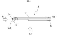
- FIG. It is the side view which looked at the cutting insert shown in FIG. 4 from B1 direction. It is the side view which looked at the cutting insert shown in FIG. 4 from B2 direction.
- FIG. 9 is an enlarged view of a region A5 shown in FIG. 8;
- FIG. 9 is an enlarged view of a region A5 shown in FIG. 8;
- FIG. 9 is an enlarged view of a region A5 shown in FIG. 8;
- FIG. 9 is an enlarged view of
- FIG. 10 is an enlarged view of a region A6 shown in FIG. 9;
- FIG. 7 is a cross-sectional view showing the XI-XI cross section in FIG. 6;
- FIG. 7 is a sectional view showing the XII-XII section in FIG. 6;
- 1 is a perspective view of a non-limiting one-sided cutting tool of the present disclosure;
- FIG. 14 is a top view of the cutting tool shown in FIG. 13;
- FIG. 1 is a schematic diagram illustrating a step in the non-limiting method of manufacturing a one-sided machined workpiece of the present disclosure;
- FIG. 1 is a schematic diagram illustrating a step in the non-limiting method of manufacturing a one-sided machined workpiece of the present disclosure;
- FIG. 1 is a schematic diagram illustrating a step in the non-limiting method of manufacturing a one-sided machined workpiece of the present disclosure;
- FIG. 1 is a schematic diagram illustrating a step in the non-limiting method of manufacturing
- a non-limiting one-sided cutting insert 1 (hereinafter also simply referred to as insert 1) in the present disclosure will be described in detail with reference to the drawings.
- insert 1 may comprise any components not shown in the referenced figures.
- the dimensions of the members in each drawing do not necessarily represent the actual dimensions of the constituent members, the dimensional ratios of the respective members, and the like faithfully.
- the insert 1 is generally rod-shaped overall and has a first portion 3 and a second portion 5, as in the non-limiting example shown in FIG.
- the first portion 3 is a bar-shaped portion extending along the central axis O1 from the front end 3a toward the rear end 3b, and serves as the base of the insert 1.
- the first portion 3 in one non-limiting example shown in FIG. 1 is generally cylindrical.
- the insert 1 is fixed to the holder by attaching the first portion 3 to a holder which will be described later.
- the “central axis O1” is an axis along the longitudinal direction of the first portion 3, and the center of at least either the front end 3a side or the rear end 3b side of the first portion 3 is It is the axis that passes through.
- an axis along the longitudinal direction passing through the center of gravity of the first portion 3 when viewed from the rear end 3b side may be regarded as the central axis O1.
- the size of the first part 3 is not limited to a specific value.
- the length of the first portion 3 in the direction along the central axis O1 can be set to 30 to 80 mm, for example.
- the maximum width of the first portion 3 in the direction orthogonal to the central axis O1 can be set to 3 to 10 mm, for example.
- the second portion 5 protrudes in a direction orthogonal to the central axis O1 from a portion of the first portion 3 on the tip 3a side. At this time, the second portion 5 may not protrude from the portion including the tip 3a of the first portion 3, but in a non-limiting example shown in FIG. It protrudes in a direction perpendicular to the central axis O1 from the portion including the .
- the second portion 5 has a cutting edge 7 as described later, and plays a major role during cutting of the work material. Therefore, the first portion 3 of the insert 1 may be called the base portion, and the second portion 5 may be called the cutting portion.
- the first part 3 and the second part 5 may be separate members, or may be integrally formed. In one non-limiting example shown in FIG. 1, the first part 3 and the second part 5 are integrally formed.
- the second part 5 has an upper surface 9 , a cutting edge 7 , a rising surface 11 , an upper end surface 5 a and a connecting surface 13 .
- the top surface 9 is triangular with a first corner 15 , a first side 17 and a second side 19 .
- a first corner 15 of the upper surface 9 protrudes in a direction orthogonal to the central axis O1. Therefore, the first corner 15 is the farthest from the first portion 3 on the upper surface 9 .
- the first corner 15 need not be a corner in the strict sense.
- the first corner 15 in one non-limiting example shown in FIG.
- the first corner 15 may be arc-shaped.
- the first side 17 and the second side 19 extend from the first corner 15 respectively.
- the first side 17 and the second side 19 each extend from the first corner 15 toward the first portion 3 .
- the distance between the first side 17 and the second side 19 increases with increasing distance from the first corner 15 .
- the first side 17 is located on the side of the leading edge 3a and the second side 19 is located on the side of the trailing edge 3b. That is, the second side 19 is located closer to the rear end 3b than the first side 17 is.
- the first side 17 and the second side 19 may each have a linear shape.
- the size of the upper surface 9 is not limited to a specific value.
- the width of the upper surface 9 in the direction along the central axis O1 when viewed from the front can be set to 0.1 to 3 mm, for example.
- the width of the upper surface 9 in the direction orthogonal to the central axis O1 when viewed from the front can be set to 0.08 to 2 mm, for example.
- viewing the upper surface 9 from the front may be referred to as viewing from the top.
- a first side 17, a second side 19, and a first corner 15 on the upper surface 9 are separated from the first portion 3, and form an outer edge of the insert 1 when viewed from above.
- the cutting edge 7 is located on at least part of the first side 17 , the second side 19 and the first corner 15 . By bringing this cutting edge 7 into contact with the work material, the work material can be cut.
- the rising surface 11 is a surface located closer to the first part 3 than the top surface 9 and is inclined with respect to the top surface 9 . Specifically, the rising surface 11 is inclined upward with distance from the upper surface 9 .
- the rising surface 11 is a surface positioned forward in the traveling direction of chips generated by the cutting edge 7 , and the chips can come into contact with the rising surface 11 . By bringing the chips into contact with the rising surface 11, the chips can be controlled by slowing down the flow speed of the chips, changing the direction of the flow of the chips, and deforming the chips.
- the upper end surface 5 a is a surface positioned closer to the first portion 3 than the rising surface 11 and is the surface positioned highest in the second portion 5 .
- the top surface 5a in one non-limiting example shown in FIG. 5 is flat.
- the upper end surface 5a in the non-limiting example shown in FIG. 10 is parallel to the central axis O1.
- the upper end surface 5a may be used as a reference plane for adjusting the position of the cutting edge 7 in the vertical direction.
- the upper surface 9 in the non-limiting example shown in FIG. 10 is slightly inclined with respect to the upper end surface 5a. Specifically, when the upper end face 5a is used as a reference plane, the upper face 9 is slightly inclined downward as it approaches the rear end 3b.
- connection surface 13 is located between the top surface 9 and the rising surface 11 and is connected to the top surface 9 and the rising surface 11 .
- top surface 9 and rising surface 11 are flat, while connecting surface 13 is concave.
- the connecting surface 13 is indicated by a concave curve.
- a surface formed by the upper surface 9, the rising surface 11, and the connecting surface 13 of the second portion 5 has a concave shape as a whole.
- the bisector of the first angle 15 may be replaced with the bisector of the angle formed by the tangents at both ends of the first angle, for example, when the first angle 15 has a convex curved shape or an arc shape. . Further, for example, when the first corner 15 is connected to the first side 17 and the second side 19 and the first side 17 and the second side 19 are linear, the first side 17 and the second side 19 are connected to each other.
- the angle formed by the imaginary extension lines extending from the sides 19 may be replaced with the bisector of the first angle 15 .
- the cross section including the bisector of the first angle 15 is a cross section including the entire bisector of the first angle 15 . In the cutting tool of the present disclosure, for convenience of explanation, a part of the above-described first cross section is enlarged and shown in the drawing.
- the upper surface 9 is slightly inclined with respect to the upper end surface 5a. Therefore, the first cross section is perpendicular to the upper end surface 5 a and is inclined with respect to the upper surface 9 . "Oblique” here is intended to be neither orthogonal nor parallel. The first cross section may be inclined with respect to the upper surface 9 and perpendicular to the rising surface 11 .
- the insert 1 does not have the connection surface 13 and the top surface 9 and the rising surface 11 are connected, chips may clog near the boundary between the top surface 9 and the rising surface 11 .
- the connecting surface 13 having a concave surface shape is positioned between the upper surface 9 and the rising surface 11, chip clogging is less likely to occur.
- the second part 5 may have side surfaces 21 .
- the side surfaces 21 are connected to the first corner 15 , the first side 17 and the second side 19 of the top surface 9 . Therefore, it can be said that the cutting edge 7 is located at the intersection of the upper surface 9 and the side surface 21 .
- a side surface 21 located along the cutting edge 7 may function as a so-called clearance surface.
- the upper surface 9 may function as a so-called rake surface.
- the side surface 21 may have a first side surface 21a, a second side surface 21b and a corner side surface 21c.
- the first side surface 21 a is connected to the first side 17 .
- the second side surface 21 b is connected to the second side 19 .
- the corner side 21 c is connected to the first corner 15 .
- the first side 21a connected to the first side 17 and the second side 21b connected to the second side 19 may each be flat.
- the side surface 21 functions as a flank
- the first side surface 21a and the second side surface 21b may approach each other as the distance from the upper surface 9 increases.
- the corner side surface 21c connected to the first corner 15 may have a convex curved shape.
- the imaginary extension line L1 of the upper surface 9 and the imaginary extension line L2 of the rising surface 11 may intersect at an acute angle. If these imaginary extension lines L1 and L2 intersect at an obtuse angle, depending on the cutting conditions, it may be difficult to sufficiently reduce the flow rate of chips on the rising surface 11 . Therefore, there is a possibility that the control of the chips becomes difficult when the chips climb over the rising surface 11 .
- the flow speed of chips can be sufficiently slowed down, and the chips tend to curl.
- the chips tend to advance parallel to the upper surface 9 .
- the chips tend to advance parallel to the rising surface 11 .
- the traveling direction of the chips traveling along the rising surface 11 includes a component that is reversed with respect to the traveling direction of the chips traveling along the upper surface 9 . Therefore, chips tend to curl as described above.
- the angle ⁇ at which imaginary extension lines L1 and L2 intersect in the first cross section is not limited to a specific value as long as it is an acute angle.
- the angle ⁇ may be set to, for example, approximately 75° to 89.8°. When the angle ⁇ is 75° or more, the connecting surface 13 is less likely to be clogged with chips. Further, when the angle ⁇ is 89.8° or less, chips are stable and tend to curl.
- the virtual extension lines L1 and L2 may be evaluated by the following procedure. First, in the first cross section, a tangent line that contacts the top surface 9 and the connection surface 13 at the boundary between the top surface 9 and the connection surface 13 is specified. This tangent line may be the imaginary extension line L1. Also, in the first cross section, a tangent line that contacts the rising surface 11 and the connecting surface 13 at the boundary between the rising surface 11 and the connecting surface 13 is specified. This tangent line may be the imaginary extension line L2.
- connection surface 13 in a non-limiting example shown in FIG. 6 has a groove shape extending in a direction inclined with respect to the central axis O1. At this time, the groove-shaped connecting surface 13 may be inclined away from the central axis O1 as it approaches the rear end 3b.
- the inclination angle ⁇ 1 of the extending direction of the connecting surface 13 with respect to the central axis O1 when viewed from above is not limited to a specific value, and may be 0° ⁇ 90°. In particular, when the inclination angle ⁇ 1 satisfies 0° ⁇ 45°, the chip discharging property is excellent. When chips come into contact with the connection surface 13 and change direction of flow, if the inclination angle ⁇ 1 is greater than 45°, the chips tend to flow in the direction perpendicular to the central axis O1, but the inclination angle ⁇ 1 is greater than 45°. This is because chips tend to flow toward the rear end 3b when they are small.
- the portion of the cutting edge 7 located on the first side 17 is called the major cutting edge 7 and is often used as the main edge in cutting. This is because the chips generated by the main cutting edge 7 located on the first side 17 tend to advance toward the rear end 3b, resulting in excellent chip discharging performance.
- the groove-shaped connection surface 13 is inclined as described above, chips traveling toward the rear end 3b are likely to come into contact with the connection surface 13 . Therefore, it is easy to control the flow of chips on the connection surface 13 .
- the rising surface 11 may be inclined with respect to the central axis O1 so as to move away from the central axis O1 as it approaches the rear end 3b when viewed from above. In this case, chips advancing toward the rear end 3 b easily come into contact with the rising surface 11 . Therefore, the flow of chips is easily controlled on the rising surface 11 .
- the upper surface 9 may be parallel to the central axis O1, or may be inclined.
- the upper surface 9 may slope downward as it approaches the rear end 3b.
- an imaginary straight line O2 parallel to the central axis O1 is set to facilitate visual understanding of the tilt angle ⁇ 2, and the angle formed by the imaginary straight line O2 and the top surface 9 indicates the tilt angle ⁇ 2.
- connection surface 13 may be open to the second side surface 21b. Chips whose flow is controlled at the connection surface 13 tend to stably advance toward the rear end 3b, and the insert 1 tends to be excellent in chip discharging performance. Also, the connection surface 13 may be open to the first side surface 21a.
- connection surface 13 is open to the first side surface 21a, even when chips advance toward the tip 3a, the chip discharging performance is excellent. That is, when the connection surface 13 is open to the first side surface 21a and the second side surface 21b, the insert 1 is less subject to structural limitations of the work material and has excellent versatility.
- the width W1 of the rising surface 11 may increase as it moves away from the first side 17 and approaches the second side 19 .
- the flow direction of the chips tends to vary more as it approaches the rear end 3b, in other words, as it moves away from the first side 17 and approaches the second side 19.
- the width W1 of the rising surface 11 is configured as described above, the flow of chips can be stably controlled even if the direction of the flow of chips varies.
- the width W1 of the entire rising surface 11 is not large, the size of the insert 1 can be reduced.
- the width W2 of the connection surface 13 may be constant from the first side 17 toward the second side 19. Chips tend to curl when they come into contact with the connecting surface 13 having a concave surface shape. If the width W2 of the connecting surface 13 changes from the first side 17 toward the second side 19, the chips tend to curl into a truncated cone shape as a whole. Therefore, chips tend to form large clumps. On the other hand, when the width W2 of the connecting surface 13 is constant as described above, the chips as a whole tend to have an elongated shape such as a spiral shape. Therefore, it is excellent in chip discharge property.
- the width W2 of the connecting surface 13 may be larger than the width W1 of the rising surface 11 in the first cross section as in a non-limiting example shown in FIG. In such a case, since the space of the connection surface 13 is easily secured, the chips tend to curl stably and clogging of the chips is less likely to occur, resulting in excellent chip discharging performance.
- the upper surface 9 and the rising surface 11 may each be flat. If the upper surface 9 is flat, the contact area of the chips on the upper surface 9 and the rising surface 11 can be reduced when the chips pass over the upper surface 9, the connecting surface 13 and the rising surface 11 while curling. Therefore, the upper surface 9 and the rising surface 11 are less likely to wear, and the durability of the insert 1 is high.
- connection surface 13 may be arc-shaped, and the radius of curvature R1 of the connection surface 13 may be larger than the width W1 of the rising surface 11. In such a case, since the chips tend to curl gently, chip clogging is less likely to occur and chip discharge is excellent.
- connection surface 13 in the first cross section has an arc shape
- the curvature radius R1 of the connection surface 13 may be constant from the first side 17 toward the second side 19 .
- the chips as a whole tend to have an elongated shape such as a helical shape rather than a truncated cone shape. Therefore, it is excellent in chip discharge property.
- the connecting surface 13 may have an elliptical arc shape, and the maximum value of the curvature radius R1 of the connecting surface 13 may be larger than the width W1 of the rising surface 11.
- it is vertically elongated, in other words, it has an elliptical arc shape whose major axis is in the vertical direction. In such a case, the chips smoothly progress from the connecting surface 13 to the rising surface 11, so that chip clogging is less likely to occur and the chip discharging performance is excellent.
- Constant does not have to be exactly the same value. This is a concept that allows for variations that are unavoidable in manufacturing. Specifically, if the minimum value is 95% or more of the maximum value, it may be evaluated as constant. For example, when the width W2 of the connection surface 13 is constant from the first side 17 to the second side 19, the minimum value of the width W2 of the connection surface 13 is 95 times the maximum value of the width W2 of the connection surface 13. ⁇ 100% is sufficient.
- Examples of materials for the insert 1 include cemented carbide and cermet.
- Cemented carbide compositions may include, for example, WC-Co, WC-TiC-Co and WC-TiC-TaC-Co.
- WC, TiC and TaC may be hard particles and Co may be the binder phase.
- the cermet may be a sintered composite material in which a metal is combined with a ceramic component.
- An example of a cermet may be a titanium compound based on titanium carbide (TiC) or titanium nitride (TiN).
- TiC titanium carbide
- TiN titanium nitride
- the material of the insert 1 is not limited to the above composition.
- the surface of the insert 1 may be coated with a coating using chemical vapor deposition (CVD) or physical vapor deposition (PVD) methods.
- the composition of the coating may include titanium carbide (TiC), titanium nitride (TiN), titanium carbonitride (TiCN), alumina (Al 2 O 3 ), and the like.
- the cutting tool 101 may have a bar-shaped holder 105 extending from the first end 105a toward the second end 105b, as in a non-limiting example shown in FIGS.
- the holder 105 may have a pocket 103 (insert pocket) located on the side of the first end 105a.
- the cutting tool 101 may comprise the insert 1 described above located in the pocket 103 .
- the insert 1 may be mounted such that at least part of the cutting edge 7 protrudes from the first end 105 a of the holder 105 .
- the holder 105 may have an elongated bar shape.
- One pocket 103 may be provided on the first end 105a side of the holder 105 .
- the pocket 103 is a portion to which the insert 1 is mounted, and may be open to the end face of the holder 105 on the side of the first end 105a.
- the insert 1 may be fixed to the holder 105 by screws 107, as a non-limiting example shown in FIG.
- the holder 105 may be provided with a threaded hole, and the insert 1 may be constrained in the pocket 103 by inserting the screw 107 into the threaded hole and pressing the screw 107 against the insert 1 .
- Steel, cast iron, or the like may be used as the member of the holder 105 .
- the toughness of the holder 105 is high.
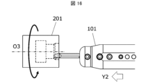
- the cutting work 203 is produced by cutting the work material 201 .
- the manufacturing method of the cut workpiece 203 in the embodiment includes the following steps. i.e. (1) a step of rotating the work material 201; (2) contacting the rotating work material 201 with the cutting tool 101 represented by the above embodiment; (3) separating the cutting tool 101 from the work material 201; Prepare.
- the work material 201 may be rotated around the axis O3 and the cutting tool 101 may be brought relatively closer to the work material 201.
- the cutting tool 101 may be brought relatively closer to the work material 201.
- at least a portion of the cutting edge 7 of the cutting tool 101 may be brought into contact with the work material 201 to cut the work material 201 .
- the cutting tool 101 may be kept relatively away from the work material 201 .
- the cutting tool 101 is moved in the Y1 direction with the axis O3 fixed and the work material 201 rotated, thereby bringing the cutting tool 101 closer to the work material 201. good too.
- the cutting tool 101 is moved in the Y2 direction while at least a portion of the cutting edge 7 of the insert 1 is in contact with the rotating work 201. You may cut the cut material 201 by making it carry out.
- the cutting tool 101 may be moved away from the work material 201 by moving the cutting tool 101 in the Y3 direction while the work material 201 is being rotated.
- the cutting tool 101 In each process, by moving the cutting tool 101, the cutting tool 101 is brought into contact with the work material 201, or the cutting tool 101 is separated from the work material 201, but it is of course not limited to such a form. .
- step (1) the work material 201 may be brought closer to the cutting tool 101 . Also, in the step (3), the work material 201 may be kept away from the cutting tool 101 . When cutting is continued, the process of keeping the work material 201 rotated and bringing at least part of the cutting edge 7 of the insert 1 into contact with a different location on the work material 201 may be repeated. .
- Representative examples of the material of the work material 201 include hardened steel, carbon steel, alloy steel, stainless steel, cast iron, non-ferrous metals, and the like.
- Cutting insert (insert) 3 First portion 3a Front end 3b Rear end 5 Second portion 5a Upper end surface 7 Cutting edge 9 Upper surface 11 Rising surface 13 Connection Surface 15 First corner 17 First side 19 Second side 21 Side 21a First side 21b Second side 21c Corner side 101 Cutting tool 103... Pocket 105... Holder 107... Screw 201... Work material 203... Cut workpiece O1... Center axis O2... Imaginary straight line L1...
Abstract
There is a demand for a cutting insert that enables performing cutting work on a cutting object under a wide range of cutting conditions. This cutting insert has a rod-shaped first portion and a second portion that protrudes from a leading end of the first portion. The second portion has an upper surface, a cutting edge, a rising surface, and a recessed curved connection surface. The rising surface is disposed at a location closer to the first portion as compared with the upper surface, and becomes tilted upward as the distance from the upper surface increases. The connection surface is disposed between the upper surface and the rising surface, and is connected to the upper surface and the rising surface. Further, in a cross-section that contains the bisector of a first vertex, a virtual extended line of the upper surface and a virtual extended line of the rising surface intersect with each other at an acute angle.
Description
本開示は、被削材の切削加工に用いられる切削インサート、切削工具、及び切削加工物の製造方法に関する。被削材の切削加工としては、例えば旋削加工及び転削加工が挙げられる。旋削加工としては、例えば外径加工、内径加工、溝入れ加工及び突切り加工が挙げられる。
The present disclosure relates to a cutting insert, a cutting tool, and a method of manufacturing a cut product used for cutting a work material. The cutting of the work material includes, for example, turning and milling. Turning includes, for example, outer diameter machining, inner diameter machining, grooving and parting off.
金属材料等からなる被削材を切削加工する際に用いられる切削工具は、例えば特許文献1において議論されている。特許文献1に記載の切削工具は、切削インサート及びホルダを有する。切削インサートは、すくい面、逃げ面、切れ刃及び壁面を有する。すくい面は、切れ刃から離れるに従って下方に向かって傾斜しており、壁面は、すくい面から離れるに従って上方に向かって傾斜している。
Patent Document 1, for example, discusses a cutting tool used for cutting a work material made of a metal material or the like. The cutting tool described in Patent Document 1 has a cutting insert and a holder. A cutting insert has a rake face, a flank face, a cutting edge and a wall surface. The rake face slopes downward with distance from the cutting edge, and the wall surface slopes upward with distance from the rake face.
本開示に係る切削インサートは、先端から後端に向かって中心軸に沿って延びた棒形状の第1部位と、前記先端から前記中心軸に直交する方向に突出した第2部位と、を有する。前記第2部位は、正面視した場合に三角形状であって、前記第1部位から突出した第1角と、前記第1角から前記第1部位に向かって延びた第1辺と、前記第1角から前記第1部位に向かって延びるとともに前記第1辺よりも前記後端部の近くに位置する第2辺と、を有する上面と、前記第1角、前記第1辺及び前記第2辺の少なくとも一部に位置する切刃と、前記上面よりも前記第1部位の近くに位置し、前記上面から離れるにしたがって上方に向かって傾斜した立ち上がり面と、前記立ち上がり面よりも前記第1部位の近くに位置する上端面と、前記上面及び前記立ち上がり面の間に位置して、前記上面及び前記立ち上がり面に接続された凹曲面形状の接続面と、を有する。また、前記上端面に直交するとともに前記第1角の二等分線を含む断面において、前記上面の仮想延長線及び前記立ち上がり面の仮想延長線が鋭角に交わる。
A cutting insert according to the present disclosure has a rod-shaped first portion extending along a central axis from a tip toward a rear end, and a second portion protruding from the tip in a direction orthogonal to the central axis. . The second portion has a triangular shape when viewed from the front, and includes a first corner projecting from the first portion, a first side extending from the first corner toward the first portion, and the first corner protruding from the first portion. a second side extending from one corner toward the first portion and located closer to the rear end than the first side; the first corner, the first side, and the second side; a cutting edge located on at least a part of a side; a rising surface located closer to the first portion than the top surface and inclined upward as the distance from the top surface increases; It has an upper end surface located near the part, and a connecting surface having a concave shape located between the top surface and the rising surface and connected to the top surface and the rising surface. Further, in a cross section orthogonal to the upper end surface and including the bisector of the first angle, the imaginary extension line of the upper surface and the imaginary extension line of the rising surface intersect at an acute angle.
本開示における限定されない一面の切削インサート1(以下、単にインサート1ともいう。)について図面を用いて詳細に説明する。但し、以下で参照する各図は、説明の便宜上、限定されない実施形態を説明する上で必要な主要部材のみを簡略化して示したものである。したがって、インサート1は、参照する各図に示されていない任意の構成部材を備え得る。また、各図中の部材の寸法は、実際の構成部材の寸法及び各部材の寸法比率等を忠実に表すとは限らない。
A non-limiting one-sided cutting insert 1 (hereinafter also simply referred to as insert 1) in the present disclosure will be described in detail with reference to the drawings. However, for convenience of explanation, each figure referred to below is a simplified representation of only the main members necessary to explain non-limiting embodiments. Accordingly, the insert 1 may comprise any components not shown in the referenced figures. Also, the dimensions of the members in each drawing do not necessarily represent the actual dimensions of the constituent members, the dimensional ratios of the respective members, and the like faithfully.
<切削インサート>
インサート1は、図1に示す限定されない一例のように、全体として概ね棒形状であり、第1部位3及び第2部位5を有している。第1部位3は、先端3aから後端3bに向かって中心軸O1に沿って延びた棒形状であり、インサート1におけるベースとなる部分である。図1に示す限定されない一例における第1部位3は、概ね円柱形状である。この第1部位3を後述するホルダに取り付けることによって、インサート1がホルダに固定される。 <Cutting insert>
Theinsert 1 is generally rod-shaped overall and has a first portion 3 and a second portion 5, as in the non-limiting example shown in FIG. The first portion 3 is a bar-shaped portion extending along the central axis O1 from the front end 3a toward the rear end 3b, and serves as the base of the insert 1. As shown in FIG. The first portion 3 in one non-limiting example shown in FIG. 1 is generally cylindrical. The insert 1 is fixed to the holder by attaching the first portion 3 to a holder which will be described later.
インサート1は、図1に示す限定されない一例のように、全体として概ね棒形状であり、第1部位3及び第2部位5を有している。第1部位3は、先端3aから後端3bに向かって中心軸O1に沿って延びた棒形状であり、インサート1におけるベースとなる部分である。図1に示す限定されない一例における第1部位3は、概ね円柱形状である。この第1部位3を後述するホルダに取り付けることによって、インサート1がホルダに固定される。 <Cutting insert>
The
本開示において、「中心軸O1」とは、第1部位3の長手方向に沿った軸のことであり、第1部位3における先端3aの側又は後端3bの側の少なくともいずれかの中心を通る軸のことである。例えば、後端3bの側から見た場合における第1部位3の重心を通り、長手方向に沿った軸を中心軸O1と見做してもよい。
In the present disclosure, the “central axis O1” is an axis along the longitudinal direction of the first portion 3, and the center of at least either the front end 3a side or the rear end 3b side of the first portion 3 is It is the axis that passes through. For example, an axis along the longitudinal direction passing through the center of gravity of the first portion 3 when viewed from the rear end 3b side may be regarded as the central axis O1.
第1部位3の大きさは特定の値に限定されない。中心軸O1に沿った方向における第1部位3の長さは、例えば、30~80mmに設定できる。中心軸O1に直交する方向における第1部位3の幅の最大値は、例えば、3~10mmに設定できる。
The size of the first part 3 is not limited to a specific value. The length of the first portion 3 in the direction along the central axis O1 can be set to 30 to 80 mm, for example. The maximum width of the first portion 3 in the direction orthogonal to the central axis O1 can be set to 3 to 10 mm, for example.
第2部位5は、第1部位3における先端3aの側の部位から中心軸O1に直交する方向に突出している。このとき、第2部位5は、第1部位3における先端3aを含む部分から突出していなくてもよいが、図1に示す限定されない一例においては、第2部位5が第1部位3における先端3aを含む部分から中心軸O1に直交する方向に突出している。
The second portion 5 protrudes in a direction orthogonal to the central axis O1 from a portion of the first portion 3 on the tip 3a side. At this time, the second portion 5 may not protrude from the portion including the tip 3a of the first portion 3, but in a non-limiting example shown in FIG. It protrudes in a direction perpendicular to the central axis O1 from the portion including the .
第2部位5は、後述するように切刃7を有しており、被削材の切削加工時に主たる役割を果たす。そのため、インサート1における第1部位3を基部、第2部位5を切削部と呼んでもよい。第1部位3及び第2部位5は別部材であってもよく、また、一体的に形成されていてもよい。図1に示す限定されない一例においては、第1部位3及び第2部位5が一体的に形成されている。
The second portion 5 has a cutting edge 7 as described later, and plays a major role during cutting of the work material. Therefore, the first portion 3 of the insert 1 may be called the base portion, and the second portion 5 may be called the cutting portion. The first part 3 and the second part 5 may be separate members, or may be integrally formed. In one non-limiting example shown in FIG. 1, the first part 3 and the second part 5 are integrally formed.
第2部位5は、上面9、切刃7、立ち上がり面11、上端面5a及び接続面13を有する。上面9は、第1角15、第1辺17及び第2辺19を有する三角形状である。上面9における第1角15が、中心軸O1に直交する方向に突出している。そのため、第1角15は上面9において第1部位3から最も離れている。第1角15は、厳密な意味での角である必要はない。図3に示す限定されない一例における第1角15は、第1部位3から離れる方向に向かって突出した凸曲線形状である。第1角15は、円弧形状であってもよい。
The second part 5 has an upper surface 9 , a cutting edge 7 , a rising surface 11 , an upper end surface 5 a and a connecting surface 13 . The top surface 9 is triangular with a first corner 15 , a first side 17 and a second side 19 . A first corner 15 of the upper surface 9 protrudes in a direction orthogonal to the central axis O1. Therefore, the first corner 15 is the farthest from the first portion 3 on the upper surface 9 . The first corner 15 need not be a corner in the strict sense. The first corner 15 in one non-limiting example shown in FIG. The first corner 15 may be arc-shaped.
第1辺17及び第2辺19は、それぞれ第1角15から延びている。第1辺17及び第2辺19は、それぞれ第1角15から第1部位3に向かって延びている。第1辺17及び第2辺19の間隔は、第1角15から離れるにしたがって広がっている。図3に示す限定されない一例において、第1辺17は先端3aの側に位置し、第2辺19は後端3bの側に位置する。すなわち、第2辺19は、第1辺17よりも後端3bの近くに位置する。第1辺17及び第2辺19は、それぞれ直線形状であってもよい。
The first side 17 and the second side 19 extend from the first corner 15 respectively. The first side 17 and the second side 19 each extend from the first corner 15 toward the first portion 3 . The distance between the first side 17 and the second side 19 increases with increasing distance from the first corner 15 . In one non-limiting example shown in FIG. 3, the first side 17 is located on the side of the leading edge 3a and the second side 19 is located on the side of the trailing edge 3b. That is, the second side 19 is located closer to the rear end 3b than the first side 17 is. The first side 17 and the second side 19 may each have a linear shape.
上面9の大きさは特定の値に限定されない。正面視した場合における中心軸O1に沿った方向での上面9の幅は、例えば、0.1~3mmに設定できる。正面視した場合における中心軸O1に直交する方向での上面9の幅は、例えば、0.08~2mmに設定できる。本開示において、上面9を正面視することを、上面視と言い換えてもよい。
The size of the upper surface 9 is not limited to a specific value. The width of the upper surface 9 in the direction along the central axis O1 when viewed from the front can be set to 0.1 to 3 mm, for example. The width of the upper surface 9 in the direction orthogonal to the central axis O1 when viewed from the front can be set to 0.08 to 2 mm, for example. In the present disclosure, viewing the upper surface 9 from the front may be referred to as viewing from the top.
上面9における第1辺17、第2辺19及び第1角15は、第1部位3から離れており、上面視した場合におけるインサート1の外縁を構成している。切刃7は、これら第1辺17、第2辺19及び第1角15の少なくとも一部に位置している。この切刃7を被削材に接触させることによって、被削材の切削加工を行うことができる。
A first side 17, a second side 19, and a first corner 15 on the upper surface 9 are separated from the first portion 3, and form an outer edge of the insert 1 when viewed from above. The cutting edge 7 is located on at least part of the first side 17 , the second side 19 and the first corner 15 . By bringing this cutting edge 7 into contact with the work material, the work material can be cut.
立ち上がり面11は、上面9よりも第1部位3の近くに位置する面であり、上面9に対して傾斜している。具体的には、立ち上がり面11は、上面9から離れるにしたがって上方に向かって傾斜している。立ち上がり面11は、切刃7で生じた切屑の進行方向の前方に位置する面であり、切屑は立ち上がり面11に接触し得る。切屑を立ち上がり面11に接触させることによって、切屑の流れる速度を遅くする、切屑の流れる方向を変える、切屑を変形させる、といった切屑の制御を行うことができる。
The rising surface 11 is a surface located closer to the first part 3 than the top surface 9 and is inclined with respect to the top surface 9 . Specifically, the rising surface 11 is inclined upward with distance from the upper surface 9 . The rising surface 11 is a surface positioned forward in the traveling direction of chips generated by the cutting edge 7 , and the chips can come into contact with the rising surface 11 . By bringing the chips into contact with the rising surface 11, the chips can be controlled by slowing down the flow speed of the chips, changing the direction of the flow of the chips, and deforming the chips.
上端面5aは、立ち上がり面11よりも第1部位3の近くに位置する面であり、第2部位5において最も上方に位置する面である。図5に示す限定されない一例における上端面5aは、平らである。また、図10に示す限定されない一例における上端面5aは、中心軸O1に平行である。上端面5aが中心軸O1に平行である場合には、上端面5aを基準面として、上下方向における切刃7の位置調整に利用してもよい。
The upper end surface 5 a is a surface positioned closer to the first portion 3 than the rising surface 11 and is the surface positioned highest in the second portion 5 . The top surface 5a in one non-limiting example shown in FIG. 5 is flat. Also, the upper end surface 5a in the non-limiting example shown in FIG. 10 is parallel to the central axis O1. When the upper end surface 5a is parallel to the central axis O1, the upper end surface 5a may be used as a reference plane for adjusting the position of the cutting edge 7 in the vertical direction.
図10に示す限定されない一例における上面9は、上端面5aに対して僅かに傾斜している。具体的には、上端面5aを基準面とした場合に、上面9は、後端3bに近づくにしたがって下方に向かうように僅かに傾斜している。
The upper surface 9 in the non-limiting example shown in FIG. 10 is slightly inclined with respect to the upper end surface 5a. Specifically, when the upper end face 5a is used as a reference plane, the upper face 9 is slightly inclined downward as it approaches the rear end 3b.
接続面13は、上面9及び立ち上がり面11の間に位置しており、上面9及び立ち上がり面11に接続されている。図2に示す限定されない一例において、上面9及び立ち上がり面11が平らである一方で、接続面13は凹曲面形状である。具体的には、上端面5aに直交するとともに第1角15の二等分線を含む断面(以下、第1断面としてもよい。)において、上面9及び立ち上がり面11が直線で示される一方で、接続面13は凹曲線で示される。第2部位5における、上面9、立ち上がり面11及び接続面13によって構成される面は、全体として凹形状となっている。
The connection surface 13 is located between the top surface 9 and the rising surface 11 and is connected to the top surface 9 and the rising surface 11 . In one non-limiting example shown in FIG. 2, top surface 9 and rising surface 11 are flat, while connecting surface 13 is concave. Specifically, in a cross section orthogonal to the upper end surface 5a and including the bisector of the first angle 15 (hereinafter may be referred to as a first cross section), while the upper surface 9 and the rising surface 11 are indicated by straight lines, , the connecting surface 13 is indicated by a concave curve. A surface formed by the upper surface 9, the rising surface 11, and the connecting surface 13 of the second portion 5 has a concave shape as a whole.
第1角15の二等分線は、例えば、第1角15が凸曲線形状又は円弧形状である場合には、第1角の両端における接線のなす角の二等分線と置き換えてもよい。また、例えば、第1角15が、第1辺17及び第2辺19と接続されており、第1辺17及び第2辺19が直線形状である場合には、第1辺17及び第2辺19をそれぞれ延ばした仮想延長線がなす角を第1角15の二等分線と置き換えてもよい。また、第1角15の二等分線を含む断面とは、第1角15の二等分線の全体を含む断面である。本開示の切削工具においては、説明の便宜上、上記した第1断面の一部を拡大して図面に表している。
The bisector of the first angle 15 may be replaced with the bisector of the angle formed by the tangents at both ends of the first angle, for example, when the first angle 15 has a convex curved shape or an arc shape. . Further, for example, when the first corner 15 is connected to the first side 17 and the second side 19 and the first side 17 and the second side 19 are linear, the first side 17 and the second side 19 are connected to each other. The angle formed by the imaginary extension lines extending from the sides 19 may be replaced with the bisector of the first angle 15 . Moreover, the cross section including the bisector of the first angle 15 is a cross section including the entire bisector of the first angle 15 . In the cutting tool of the present disclosure, for convenience of explanation, a part of the above-described first cross section is enlarged and shown in the drawing.
図10に示す限定されない一例においては、上面9が上端面5aに対して僅かに傾斜している。そのため、第1断面は、上端面5aに直交する一方で、上面9に対して傾斜している。ここでの「傾斜」とは、直交及び平行のいずれでもないことを意図している。第1断面は、上面9に対して傾斜している一方で、立ち上がり面11に対して直交していてもよい。
In one non-limiting example shown in FIG. 10, the upper surface 9 is slightly inclined with respect to the upper end surface 5a. Therefore, the first cross section is perpendicular to the upper end surface 5 a and is inclined with respect to the upper surface 9 . "Oblique" here is intended to be neither orthogonal nor parallel. The first cross section may be inclined with respect to the upper surface 9 and perpendicular to the rising surface 11 .
インサート1が接続面13を有さず、上面9及び立ち上がり面11が接続された場合、上面9及び立ち上がり面11の境界付近で切屑が詰まる恐れがある。しかしながら、これら上面9及び立ち上がり面11の間に凹曲面形状の接続面13が位置することによって切屑詰まりが生じにくくなる。
If the insert 1 does not have the connection surface 13 and the top surface 9 and the rising surface 11 are connected, chips may clog near the boundary between the top surface 9 and the rising surface 11 . However, since the connecting surface 13 having a concave surface shape is positioned between the upper surface 9 and the rising surface 11, chip clogging is less likely to occur.
第2部位5は、側面21を有してもよい。側面21は、上面9における第1角15、第1辺17及び第2辺19に接続される。そのため、切刃7は、上面9及び側面21の交わりに位置すると言い換えてもよい。切刃7に沿って位置する側面21は、いわゆる逃げ面として機能してもよい。また、側面21が逃げ面として機能する場合において、上面9は、いわゆるすくい面として機能してもよい。
The second part 5 may have side surfaces 21 . The side surfaces 21 are connected to the first corner 15 , the first side 17 and the second side 19 of the top surface 9 . Therefore, it can be said that the cutting edge 7 is located at the intersection of the upper surface 9 and the side surface 21 . A side surface 21 located along the cutting edge 7 may function as a so-called clearance surface. Moreover, when the side surface 21 functions as a flank, the upper surface 9 may function as a so-called rake surface.
側面21は、第1側面21a、第2側面21b及びコーナ側面21cを有してもよい。第1側面21aは、第1辺17に接続されている。第2側面21bは、第2辺19に接続されている。コーナ側面21cは、第1角15に接続されている。第1辺17に接続された第1側面21a及び第2辺19に接続された第2側面21bは、それぞれ平らであってもよい。側面21が逃げ面として機能する場合において、第1側面21a及び第2側面21bは、上面9から離れるにしたがって互いに近づいていてもよい。上記したように第1角15が凸曲線形状である場合において、第1角15に接続されたコーナ側面21cは、凸曲面形状であってもよい。
The side surface 21 may have a first side surface 21a, a second side surface 21b and a corner side surface 21c. The first side surface 21 a is connected to the first side 17 . The second side surface 21 b is connected to the second side 19 . The corner side 21 c is connected to the first corner 15 . The first side 21a connected to the first side 17 and the second side 21b connected to the second side 19 may each be flat. When the side surface 21 functions as a flank, the first side surface 21a and the second side surface 21b may approach each other as the distance from the upper surface 9 increases. In the case where the first corner 15 has a convex curved shape as described above, the corner side surface 21c connected to the first corner 15 may have a convex curved shape.
図11に示す限定されない一例のように、第1断面において、上面9の仮想延長線L1及び立ち上がり面11の仮想延長線L2が鋭角に交わっていてもよい。これらの仮想延長線L1、L2が鈍角で交わる場合、切削条件によっては、立ち上がり面11において切屑の流れる速度を十分に遅くすることが困難になる。そのため、切屑が立ち上がり面11を乗り越えることによって、切屑の制御が難しくなる恐れがある。
As in a non-limiting example shown in FIG. 11, in the first cross section, the imaginary extension line L1 of the upper surface 9 and the imaginary extension line L2 of the rising surface 11 may intersect at an acute angle. If these imaginary extension lines L1 and L2 intersect at an obtuse angle, depending on the cutting conditions, it may be difficult to sufficiently reduce the flow rate of chips on the rising surface 11 . Therefore, there is a possibility that the control of the chips becomes difficult when the chips climb over the rising surface 11 .
しかしながら、仮想延長線L1、L2が鋭角に交わる場合には、切屑の流れる速度を十分に遅くすることができ、また、切屑がカールしやすくなる。切屑が上面9に沿って進行する際には、上面9に平行に切屑が進行しやすい。また、切屑が立ち上がり面11に沿って進行する際には、立ち上がり面11に平行に切屑が進行しやすい。ここで、立ち上がり面11に沿って進む際の切屑の進行方向は、上面9に沿って進む際の切屑の進行方向に対して、反転する成分を含む。そのため、上記したように切屑がカールしやすくなる。
However, when the imaginary extension lines L1 and L2 intersect at an acute angle, the flow speed of chips can be sufficiently slowed down, and the chips tend to curl. When chips advance along the upper surface 9 , the chips tend to advance parallel to the upper surface 9 . Moreover, when the chips advance along the rising surface 11 , the chips tend to advance parallel to the rising surface 11 . Here, the traveling direction of the chips traveling along the rising surface 11 includes a component that is reversed with respect to the traveling direction of the chips traveling along the upper surface 9 . Therefore, chips tend to curl as described above.
第1断面における仮想延長線L1、L2の交わる角度θは、鋭角であれば特定の値に限定されない。角度θは、例えば75°~89.8°程度に設定されてもよい。角度θが75°以上である場合には、接続面13において切屑が詰まりにくい。また、角度θが89.8°以下である場合には、切屑が安定してカールしやすい。
The angle θ at which imaginary extension lines L1 and L2 intersect in the first cross section is not limited to a specific value as long as it is an acute angle. The angle θ may be set to, for example, approximately 75° to 89.8°. When the angle θ is 75° or more, the connecting surface 13 is less likely to be clogged with chips. Further, when the angle θ is 89.8° or less, chips are stable and tend to curl.
上面9の全体及び立ち上がり面11の全体がそれぞれ平らでない場合には、以下の手順によって仮想延長線L1、L2を評価してもよい。まず、第1断面において、上面9及び接続面13の境界において上面9及び接続面13に接する接線を特定する。この接線を仮想延長線L1としてもよい。また、第1断面において、立ち上がり面11及び接続面13の境界において立ち上がり面11及び接続面13に接する接線を特定する。この接線を仮想延長線L2としてもよい。
If the entire top surface 9 and the entire rising surface 11 are not flat, the virtual extension lines L1 and L2 may be evaluated by the following procedure. First, in the first cross section, a tangent line that contacts the top surface 9 and the connection surface 13 at the boundary between the top surface 9 and the connection surface 13 is specified. This tangent line may be the imaginary extension line L1. Also, in the first cross section, a tangent line that contacts the rising surface 11 and the connecting surface 13 at the boundary between the rising surface 11 and the connecting surface 13 is specified. This tangent line may be the imaginary extension line L2.
図6に示す限定されない一例における接続面13は、中心軸O1に対して傾斜した方向に延びた溝形状である。このとき、溝形状の接続面13は、後端3bに近づくにしたがって中心軸O1から離れるように傾斜していてもよい。
The connection surface 13 in a non-limiting example shown in FIG. 6 has a groove shape extending in a direction inclined with respect to the central axis O1. At this time, the groove-shaped connecting surface 13 may be inclined away from the central axis O1 as it approaches the rear end 3b.
上面視した場合における接続面13の延びる方向の中心軸O1に対する傾斜角φ1は、特定の値に限定されず、0°<θ<90°であってもよい。特に、傾斜角φ1が0°<θ<45°である場合には、切屑排出性に優れる。切屑が接続面13に接触して流れる方向が変わる際に、傾斜角φ1が45°よりも大きい場合には切屑が中心軸O1に直交する方向に流れやすいが、傾斜角φ1が45°よりも小さい場合には切屑が後端3bに向かって流れやすいからである。
The inclination angle φ1 of the extending direction of the connecting surface 13 with respect to the central axis O1 when viewed from above is not limited to a specific value, and may be 0°<θ<90°. In particular, when the inclination angle φ1 satisfies 0°<θ<45°, the chip discharging property is excellent. When chips come into contact with the connection surface 13 and change direction of flow, if the inclination angle φ1 is greater than 45°, the chips tend to flow in the direction perpendicular to the central axis O1, but the inclination angle φ1 is greater than 45°. This is because chips tend to flow toward the rear end 3b when they are small.
一般的に、切刃7のうち第1辺17に位置する部位が主切刃7と呼ばれ、切削加工において主たる刃として用いられることが多い。これは、第1辺17に位置する主切刃7で生じた切屑が後端3bに向かって進行し易く、切屑排出性に優れるからである。そして、溝形状の接続面13が上記のように傾斜している場合には、後端3bに向かって進行する切屑が接続面13に接触しやすい。そのため、接続面13において切屑の流れが制御されやすい。
Generally, the portion of the cutting edge 7 located on the first side 17 is called the major cutting edge 7 and is often used as the main edge in cutting. This is because the chips generated by the main cutting edge 7 located on the first side 17 tend to advance toward the rear end 3b, resulting in excellent chip discharging performance. When the groove-shaped connection surface 13 is inclined as described above, chips traveling toward the rear end 3b are likely to come into contact with the connection surface 13 . Therefore, it is easy to control the flow of chips on the connection surface 13 .
切屑排出性を改善する観点から、立ち上がり面11が、上面視した場合に後端3bに近づくにしたがって中心軸O1から離れるように中心軸O1に対して傾斜していてもよい。この場合には、後端3bに向かって進行する切屑が立ち上がり面11に接触しやすい。そのため、立ち上がり面11において切屑の流れが制御されやすい。
From the viewpoint of improving chip discharge performance, the rising surface 11 may be inclined with respect to the central axis O1 so as to move away from the central axis O1 as it approaches the rear end 3b when viewed from above. In this case, chips advancing toward the rear end 3 b easily come into contact with the rising surface 11 . Therefore, the flow of chips is easily controlled on the rising surface 11 .
上面9は、中心軸O1に対して平行であってもよく、また、傾斜していてもよい。例えば、図12に示す限定されない一例のように、上面9は後端3bに近づくにしたがって下方に向かうように傾斜していてもよい。図12においては、傾斜角φ2の視覚的な理解を容易にするため、中心軸O1に平行な仮想直線O2が設定され、この仮想直線O2及び上面9のなす角によって傾斜角φ2が示される。このように上面9が傾斜している場合には、切屑が後端3bに向かって進行し易く、切屑排出性に優れる。
The upper surface 9 may be parallel to the central axis O1, or may be inclined. For example, as in a non-limiting example shown in FIG. 12, the upper surface 9 may slope downward as it approaches the rear end 3b. In FIG. 12, an imaginary straight line O2 parallel to the central axis O1 is set to facilitate visual understanding of the tilt angle φ2, and the angle formed by the imaginary straight line O2 and the top surface 9 indicates the tilt angle φ2. When the upper surface 9 is inclined in this manner, chips tend to advance toward the rear end 3b, resulting in excellent chip discharging performance.
接続面13が溝形状である場合において、接続面13が、第2側面21bに対して開口していてもよい。接続面13において流れが制御された切屑が、安定して後端3bに向かって進行しやすく、切屑排出性に優れたインサート1となりやすい。また、接続面13が、第1側面21aに対して開口していてもよい。
In the case where the connection surface 13 has a groove shape, the connection surface 13 may be open to the second side surface 21b. Chips whose flow is controlled at the connection surface 13 tend to stably advance toward the rear end 3b, and the insert 1 tends to be excellent in chip discharging performance. Also, the connection surface 13 may be open to the first side surface 21a.
被削材の構造によっては、切屑を先端3aの側に向かって排出することが求められる場合もある。接続面13が、第1側面21aに対して開口している場合には、切屑が先端3aに向かって進む場合においても切屑排出性に優れる。すなわち、接続面13が、第1側面21a及び第2側面21bに対して開口している場合には、被削材の構造の制限を受けにくい、汎用性に優れたインサート1となる。
Depending on the structure of the work material, it may be required to discharge chips toward the tip 3a side. When the connection surface 13 is open to the first side surface 21a, even when chips advance toward the tip 3a, the chip discharging performance is excellent. That is, when the connection surface 13 is open to the first side surface 21a and the second side surface 21b, the insert 1 is less subject to structural limitations of the work material and has excellent versatility.
図10に示す限定されない一例のように、立ち上がり面11の幅W1が、第1辺17から離れ第2辺19に近づくにしたがって大きくなっていてもよい。後端3bに向かって切屑が流れる際に、後端3bに近づくにしたがって、言い換えれば、第1辺17から離れて第2辺19に近づくにしたがって切屑の流れる方向のバラつきが大きくなりやすい。ここで、立ち上がり面11の幅W1が上記の構成である場合には、切屑の流れる方向がバラついたとしても安定して切屑の流れを制御できる。また、立ち上がり面11全体の幅W1が大きい構成ではないため、インサート1の小型化を図ることができる。
As in a non-limiting example shown in FIG. 10, the width W1 of the rising surface 11 may increase as it moves away from the first side 17 and approaches the second side 19 . When the chips flow toward the rear end 3b, the flow direction of the chips tends to vary more as it approaches the rear end 3b, in other words, as it moves away from the first side 17 and approaches the second side 19. Here, when the width W1 of the rising surface 11 is configured as described above, the flow of chips can be stably controlled even if the direction of the flow of chips varies. Moreover, since the width W1 of the entire rising surface 11 is not large, the size of the insert 1 can be reduced.
また、図6に示す限定されない一例のように、接続面13の幅W2は、第1辺17から第2辺19に向かって一定であってもよい。切屑が凹曲面形状の接続面13に接触することによって切屑がカールしやすい。接続面13の幅W2が、第1辺17から離れて第2辺19に近づくにしたがって変化している場合には、切屑が全体として円錐台形状となるようにカールしやすい。そのため、切屑が大きな塊になりやすい。一方、接続面13の幅W2が上記のように一定である場合には、切屑が全体として螺旋形状のような細長い形状になりやすい。そのため、切屑排出性に優れる。
Further, as in a non-limiting example shown in FIG. 6, the width W2 of the connection surface 13 may be constant from the first side 17 toward the second side 19. Chips tend to curl when they come into contact with the connecting surface 13 having a concave surface shape. If the width W2 of the connecting surface 13 changes from the first side 17 toward the second side 19, the chips tend to curl into a truncated cone shape as a whole. Therefore, chips tend to form large clumps. On the other hand, when the width W2 of the connecting surface 13 is constant as described above, the chips as a whole tend to have an elongated shape such as a spiral shape. Therefore, it is excellent in chip discharge property.
図11に示す限定されない一例のように第1断面において、接続面13の幅W2が立ち上がり面11の幅W1より大きくてもよい。このような場合には、接続面13のスペースが確保されやすいため、切屑が安定してカールしやすく切屑の詰まりが生じにくく、切屑排出性に優れる。
The width W2 of the connecting surface 13 may be larger than the width W1 of the rising surface 11 in the first cross section as in a non-limiting example shown in FIG. In such a case, since the space of the connection surface 13 is easily secured, the chips tend to curl stably and clogging of the chips is less likely to occur, resulting in excellent chip discharging performance.
上記したように、上面9及び立ち上がり面11は、それぞれ平らであってもよい。上面9が平らである場合には、切屑が上面9、接続面13及び立ち上がり面11の上をカールしながら通る際に、上面9及び立ち上がり面11における切屑の接触面積を小さくできる。そのため、上面9及び立ち上がり面11が摩耗しにくく、インサート1の耐久性が高い。
As described above, the upper surface 9 and the rising surface 11 may each be flat. If the upper surface 9 is flat, the contact area of the chips on the upper surface 9 and the rising surface 11 can be reduced when the chips pass over the upper surface 9, the connecting surface 13 and the rising surface 11 while curling. Therefore, the upper surface 9 and the rising surface 11 are less likely to wear, and the durability of the insert 1 is high.
第1断面において、接続面13が円弧形状であって、接続面13の曲率半径R1が立ち上がり面11の幅W1より大きくてもよい。このような場合には、切屑が緩やかにカールしやすいため、切屑の詰まりが生じにくく切屑排出性に優れる。
In the first cross section, the connection surface 13 may be arc-shaped, and the radius of curvature R1 of the connection surface 13 may be larger than the width W1 of the rising surface 11. In such a case, since the chips tend to curl gently, chip clogging is less likely to occur and chip discharge is excellent.
第1断面における接続面13が円弧形状である場合において、接続面13の曲率半径R1は、第1辺17から第2辺19に向かって一定であってもよい。このような場合には、切屑が全体として円錐台形状ではなく螺旋形状のような細長い形状になりやすい。そのため、切屑排出性に優れる。
In the case where the connection surface 13 in the first cross section has an arc shape, the curvature radius R1 of the connection surface 13 may be constant from the first side 17 toward the second side 19 . In such a case, the chips as a whole tend to have an elongated shape such as a helical shape rather than a truncated cone shape. Therefore, it is excellent in chip discharge property.
また、図11に示す限定されない一例のように第1断面において、接続面13が楕円弧形状であって、接続面13の曲率半径R1の最大値が立ち上がり面11の幅W1より大きくてもよい。特に、図11に示す限定されない一例においては、上下方向に縦長、言い換えれば、上下方向が長軸となる楕円弧形状である。このような場合には、接続面13から立ち上がり面11への切屑の進行が円滑になるため、切屑の詰まりが生じにくく切屑排出性に優れる。
In addition, as in a non-limiting example shown in FIG. 11, in the first cross section, the connecting surface 13 may have an elliptical arc shape, and the maximum value of the curvature radius R1 of the connecting surface 13 may be larger than the width W1 of the rising surface 11. In particular, in a non-limiting example shown in FIG. 11, it is vertically elongated, in other words, it has an elliptical arc shape whose major axis is in the vertical direction. In such a case, the chips smoothly progress from the connecting surface 13 to the rising surface 11, so that chip clogging is less likely to occur and the chip discharging performance is excellent.
本開示において、「一定」とは、厳密に同じ値である必要はない。製造上で不可避な程度のバラつきを許容する概念である。具体的には、その最小値が最大値に対して95%以上であれば一定と評価してもよい。例えば、接続面13の幅W2が第1辺17から第2辺19に向かって一定であるとは、接続面13の幅W2の最小値が接続面13の幅W2の最大値に対して95~100%であればよい。
In the present disclosure, "constant" does not have to be exactly the same value. This is a concept that allows for variations that are unavoidable in manufacturing. Specifically, if the minimum value is 95% or more of the maximum value, it may be evaluated as constant. For example, when the width W2 of the connection surface 13 is constant from the first side 17 to the second side 19, the minimum value of the width W2 of the connection surface 13 is 95 times the maximum value of the width W2 of the connection surface 13. ~100% is sufficient.
インサート1の材質としては、例えば、超硬合金及びサーメットなどが挙げられ得る。超硬合金の組成としては、例えば、WC-Co、WC-TiC-Co及びWC-TiC-TaC-Coが挙げられ得る。ここで、WC、TiC及びTaCは硬質粒子であってもよく、Coは結合相であってもよい。
Examples of materials for the insert 1 include cemented carbide and cermet. Cemented carbide compositions may include, for example, WC-Co, WC-TiC-Co and WC-TiC-TaC-Co. Here, WC, TiC and TaC may be hard particles and Co may be the binder phase.
また、サーメットは、セラミック成分に金属を複合させた焼結複合材料であってもよい。サーメットの一例として、炭化チタン(TiC)又は窒化チタン(TiN)を主成分としたチタン化合物が挙げられ得る。ただし、インサート1の材質は上記の組成に限定されない。
Also, the cermet may be a sintered composite material in which a metal is combined with a ceramic component. An example of a cermet may be a titanium compound based on titanium carbide (TiC) or titanium nitride (TiN). However, the material of the insert 1 is not limited to the above composition.
インサート1の表面は、化学蒸着(CVD)法又は物理蒸着(PVD)法を用いて被膜でコーティングされてもよい。被膜の組成としては、炭化チタン(TiC)、窒化チタン(TiN)、炭窒化チタン(TiCN)及びアルミナ(Al2O3)などが挙げられ得る。
The surface of the insert 1 may be coated with a coating using chemical vapor deposition (CVD) or physical vapor deposition (PVD) methods. The composition of the coating may include titanium carbide (TiC), titanium nitride (TiN), titanium carbonitride (TiCN), alumina (Al 2 O 3 ), and the like.
<切削工具>
次に、本開示における限定されない一面の切削工具101について図面を用いて説明する。 <Cutting tool>
Next, anon-limiting cutting tool 101 in the present disclosure will be described with reference to the drawings.
次に、本開示における限定されない一面の切削工具101について図面を用いて説明する。 <Cutting tool>
Next, a
切削工具101は、図13及び図14に示す限定されない一例のように、第1端105aから第2端105bに向かって延びた棒形状のホルダ105を有してもよい。ホルダ105は、第1端105aの側に位置するポケット103(インサートポケット)を有してもよい。切削工具101は、ポケット103に位置する上記のインサート1を備えてもよい。切削工具101においては、切刃7の少なくとも一部がホルダ105の第1端105aから突出するように、インサート1が装着されてもよい。
The cutting tool 101 may have a bar-shaped holder 105 extending from the first end 105a toward the second end 105b, as in a non-limiting example shown in FIGS. The holder 105 may have a pocket 103 (insert pocket) located on the side of the first end 105a. The cutting tool 101 may comprise the insert 1 described above located in the pocket 103 . In the cutting tool 101 , the insert 1 may be mounted such that at least part of the cutting edge 7 protrudes from the first end 105 a of the holder 105 .
ホルダ105は、細長く伸びた棒形状をなしてもよい。そして、ホルダ105の第1端105aの側には、ポケット103が1つ設けられてもよい。ポケット103は、インサート1が装着される部分であり、ホルダ105における第1端105aの側の端面に対して開口してもよい。
The holder 105 may have an elongated bar shape. One pocket 103 may be provided on the first end 105a side of the holder 105 . The pocket 103 is a portion to which the insert 1 is mounted, and may be open to the end face of the holder 105 on the side of the first end 105a.
図13に示す限定されない一例のように、インサート1は、ネジ107によって、ホルダ105に固定されてもよい。例えば、ホルダ105にネジ孔が設けられ、ネジ107をネジ孔に挿入するとともに、ネジ107をインサート1に押し当てることによって、インサート1がポケット103に拘束されてもよい。
The insert 1 may be fixed to the holder 105 by screws 107, as a non-limiting example shown in FIG. For example, the holder 105 may be provided with a threaded hole, and the insert 1 may be constrained in the pocket 103 by inserting the screw 107 into the threaded hole and pressing the screw 107 against the insert 1 .
ホルダ105の部材としては、鋼、鋳鉄などが用いられてもよい。特に、これらの部材の中で鋼が用いられた場合には、ホルダ105の靱性が高い。
Steel, cast iron, or the like may be used as the member of the holder 105 . In particular, when steel is used among these members, the toughness of the holder 105 is high.
<切削加工物の製造方法>
次に、本開示における限定されない一面の切削加工物の製造方法について図面を用いて説明する。 <Manufacturing method for cutting products>
Next, a non-limiting method for manufacturing a one-sided machined product in the present disclosure will be described with reference to the drawings.
次に、本開示における限定されない一面の切削加工物の製造方法について図面を用いて説明する。 <Manufacturing method for cutting products>
Next, a non-limiting method for manufacturing a one-sided machined product in the present disclosure will be described with reference to the drawings.
切削加工物203は、被削材201を切削加工することによって作製される。実施形態における切削加工物203の製造方法は、以下の工程を備える。すなわち、
(1)被削材201を回転させる工程と、
(2)回転している被削材201に上記の実施形態に代表される切削工具101を接触させる工程と、
(3)切削工具101を被削材201から離す工程と、
を備える。 The cuttingwork 203 is produced by cutting the work material 201 . The manufacturing method of the cut workpiece 203 in the embodiment includes the following steps. i.e.
(1) a step of rotating thework material 201;
(2) contacting therotating work material 201 with the cutting tool 101 represented by the above embodiment;
(3) separating thecutting tool 101 from the work material 201;
Prepare.
(1)被削材201を回転させる工程と、
(2)回転している被削材201に上記の実施形態に代表される切削工具101を接触させる工程と、
(3)切削工具101を被削材201から離す工程と、
を備える。 The cutting
(1) a step of rotating the
(2) contacting the
(3) separating the
Prepare.
より具体的には、まず、図15に示す限定されない一例のように、被削材201を軸O3の周りで回転させるとともに、被削材201に切削工具101を相対的に近付けてもよい。次に、図16に示す限定されない一例のように、切削工具101における切刃7の少なくとも一部を被削材201に接触させて、被削材201を切削してもよい。そして、図17に示す限定されない一例のように、切削工具101を被削材201から相対的に遠ざけてもよい。
More specifically, first, as in a non-limiting example shown in FIG. 15, the work material 201 may be rotated around the axis O3 and the cutting tool 101 may be brought relatively closer to the work material 201. Next, as in a non-limiting example shown in FIG. 16 , at least a portion of the cutting edge 7 of the cutting tool 101 may be brought into contact with the work material 201 to cut the work material 201 . Then, as in a non-limiting example shown in FIG. 17 , the cutting tool 101 may be kept relatively away from the work material 201 .
図15に示す限定されない一例のように、軸O3を固定するとともに被削材201を回転させた状態で切削工具101をY1方向に移動させることによって、切削工具101を被削材201に近づけてもよい。
As in a non-limiting example shown in FIG. 15, the cutting tool 101 is moved in the Y1 direction with the axis O3 fixed and the work material 201 rotated, thereby bringing the cutting tool 101 closer to the work material 201. good too.
また、図16に示す限定されない一例のように、回転している被削材201にインサート1における切刃7として用いられる部分の少なくとも一部を接触させた状態で切削工具101をY2方向に移動させることによって、被削材201を切削してもよい。
Further, as in a non-limiting example shown in FIG. 16, the cutting tool 101 is moved in the Y2 direction while at least a portion of the cutting edge 7 of the insert 1 is in contact with the rotating work 201. You may cut the cut material 201 by making it carry out.
また、図17に示す限定されない一例のように、被削材201を回転させた状態で切削工具101をY3方向に移動させることによって、切削工具101を被削材201から遠ざけてもよい。
Further, as in a non-limiting example shown in FIG. 17, the cutting tool 101 may be moved away from the work material 201 by moving the cutting tool 101 in the Y3 direction while the work material 201 is being rotated.
それぞれの工程において、切削工具101を動かすことによって、切削工具101を被削材201に接触させる、あるいは、切削工具101を被削材201から離しているが、当然ながらこのような形態に限定されない。
In each process, by moving the cutting tool 101, the cutting tool 101 is brought into contact with the work material 201, or the cutting tool 101 is separated from the work material 201, but it is of course not limited to such a form. .
例えば、(1)の工程において、被削材201を切削工具101に近づけてもよい。また、(3)の工程において、被削材201を切削工具101から遠ざけてもよい。切削加工を継続する場合には、被削材201を回転させた状態を維持して、被削材201の異なる箇所にインサート1における切刃7の少なくとも一部を接触させる工程を繰り返してもよい。
For example, in step (1), the work material 201 may be brought closer to the cutting tool 101 . Also, in the step (3), the work material 201 may be kept away from the cutting tool 101 . When cutting is continued, the process of keeping the work material 201 rotated and bringing at least part of the cutting edge 7 of the insert 1 into contact with a different location on the work material 201 may be repeated. .
被削材201の材質の代表例としては、焼入鋼、炭素鋼、合金鋼、ステンレス、鋳鉄、又は非鉄金属などが挙げられ得る。
Representative examples of the material of the work material 201 include hardened steel, carbon steel, alloy steel, stainless steel, cast iron, non-ferrous metals, and the like.
1・・・切削インサート(インサート)
3・・・第1部位
3a・・先端
3b・・後端
5・・・第2部位
5a・・上端面
7・・・切刃
9・・・上面
11・・・立ち上がり面
13・・・接続面
15・・・第1角
17・・・第1辺
19・・・第2辺
21・・・側面
21a・・第1側面
21b・・第2側面
21c・・コーナ側面
101・・・切削工具
103・・・ポケット
105・・・ホルダ
107・・・ネジ
201・・・被削材
203・・・切削加工物
O1・・・中心軸
O2・・・仮想直線
L1・・・(上面の)仮想延長線
L2・・・(立ち上がり面の)仮想延長線
θ・・・仮想延長線の交わる角度
φ1・・・上面視における接続面の傾斜角
φ2・・・上面の傾斜角
W1・・・立ち上がり面の幅
W2・・・接続面の幅
R1・・・曲率半径
1 ... cutting insert (insert)
3First portion 3a Front end 3b Rear end 5 Second portion 5a Upper end surface 7 Cutting edge 9 Upper surface 11 Rising surface 13 Connection Surface 15 First corner 17 First side 19 Second side 21 Side 21a First side 21b Second side 21c Corner side 101 Cutting tool 103... Pocket 105... Holder 107... Screw 201... Work material 203... Cut workpiece O1... Center axis O2... Imaginary straight line L1... Imaginary (upper surface) Extension line L2: Imaginary extension line (of rising surface) θ: Intersecting angle of imaginary extension lines φ1: Inclination angle of connecting surface in top view φ2: Inclination angle of upper surface W1: Rising surface Width W2: Width of connecting surface R1: Radius of curvature
3・・・第1部位
3a・・先端
3b・・後端
5・・・第2部位
5a・・上端面
7・・・切刃
9・・・上面
11・・・立ち上がり面
13・・・接続面
15・・・第1角
17・・・第1辺
19・・・第2辺
21・・・側面
21a・・第1側面
21b・・第2側面
21c・・コーナ側面
101・・・切削工具
103・・・ポケット
105・・・ホルダ
107・・・ネジ
201・・・被削材
203・・・切削加工物
O1・・・中心軸
O2・・・仮想直線
L1・・・(上面の)仮想延長線
L2・・・(立ち上がり面の)仮想延長線
θ・・・仮想延長線の交わる角度
φ1・・・上面視における接続面の傾斜角
φ2・・・上面の傾斜角
W1・・・立ち上がり面の幅
W2・・・接続面の幅
R1・・・曲率半径
1 ... cutting insert (insert)
3
Claims (6)
- 先端から後端に向かって中心軸に沿って延びた棒形状の第1部位と、
前記先端から前記中心軸に直交する方向に突出した第2部位と、を有し、
前記第2部位は、
正面視した場合に三角形状であって、
前記第1部位から突出した第1角と、
前記第1角から前記第1部位に向かって延びた第1辺と、
前記第1角から前記第1部位に向かって延びるとともに前記第1辺よりも前記後端の近くに位置する第2辺と、を有する上面と、
前記第1角、前記第1辺及び前記第2辺の少なくとも一部に位置する切刃と、
前記上面よりも前記第1部位の近くに位置し、前記上面から離れるにしたがって上方に向かって傾斜した立ち上がり面と、
前記立ち上がり面よりも前記第1部位の近くに位置する上端面と、
前記上面及び前記立ち上がり面の間に位置して、前記上面及び前記立ち上がり面に接続された凹曲面形状の接続面と、を有し、
前記上端面に直交するとともに前記第1角の二等分線を含む断面において、前記上面の仮想延長線及び前記立ち上がり面の仮想延長線が鋭角に交わる、切削インサート。 a rod-shaped first portion extending along the central axis from the front end toward the rear end;
a second portion protruding from the tip in a direction orthogonal to the central axis;
The second part is
It has a triangular shape when viewed from the front,
a first corner protruding from the first portion;
a first side extending from the first corner toward the first portion;
a top surface having a second side extending from the first corner toward the first portion and located closer to the rear end than the first side;
a cutting edge located on at least a part of the first corner, the first side and the second side;
a rising surface located closer to the first part than the top surface and sloping upward with increasing distance from the top surface;
an upper end surface positioned closer to the first portion than the rising surface;
a concave curved connection surface located between the top surface and the rising surface and connected to the top surface and the rising surface;
A cutting insert, wherein a virtual extension line of the top surface and a virtual extension line of the rising surface intersect at an acute angle in a cross section orthogonal to the top surface and including the bisector of the first angle. - 前記立ち上がり面の幅が、前記第1辺から離れ前記第2辺に近づくにしたがって大きくなる、請求項1に記載の切削インサート。 The cutting insert according to claim 1, wherein the width of the rising surface increases away from the first side and approaches the second side.
- 前記上面及び前記立ち上がり面が、それぞれ平らである、請求項1又は2に記載の切削インサート。 The cutting insert according to claim 1 or 2, wherein the upper surface and the rising surface are each flat.
- 前記断面において、前記接続面が楕円弧形状であって、
前記接続面の曲率半径の最大値が、前記立ち上がり面の幅よりも大きい、請求項3に記載の切削インサート。 In the cross section, the connecting surface has an elliptical arc shape,
4. The cutting insert according to claim 3, wherein the maximum radius of curvature of said connecting surface is greater than the width of said rising surface. - 第1端から第2端に向かって延びた棒形状であって、第1端に位置するポケットを有するホルダと、
前記ポケットに位置する、請求項1から4のいずれか1項に記載の切削インサートと、を備える、切削工具。 a bar-shaped holder extending from a first end toward a second end and having a pocket located at the first end;
a cutting insert according to any one of claims 1 to 4 located in said pocket. - 被削材を回転させる工程と、
回転している前記被削材に請求項5に記載の切削工具を接触させる工程と、
前記切削工具を前記被削材から離す工程と、を備える、切削加工物の製造方法。 rotating the work material;
A step of bringing the cutting tool according to claim 5 into contact with the rotating work material;
and separating the cutting tool from the work material.
Applications Claiming Priority (2)
| Application Number | Priority Date | Filing Date | Title |
|---|---|---|---|
| JP2022000615 | 2022-01-05 | ||
| JP2022-000615 | 2022-01-05 |
Publications (1)
| Publication Number | Publication Date |
|---|---|
| WO2023132322A1 true WO2023132322A1 (en) | 2023-07-13 |
Family
ID=87073743
Family Applications (1)
| Application Number | Title | Priority Date | Filing Date |
|---|---|---|---|
| PCT/JP2022/048586 WO2023132322A1 (en) | 2022-01-05 | 2022-12-28 | Cutting insert, cutting tool, and method for manufacturing cut workpiece |
Country Status (1)
| Country | Link |
|---|---|
| WO (1) | WO2023132322A1 (en) |
Citations (8)
| Publication number | Priority date | Publication date | Assignee | Title |
|---|---|---|---|---|
| EP0157114A2 (en) * | 1984-02-06 | 1985-10-09 | MAPAL Fabrik für Präzisionswerkzeuge Dr. Kress KG | Cutting bit |
| JPH0497609U (en) * | 1991-01-11 | 1992-08-24 | ||
| JP2009095922A (en) * | 2007-10-16 | 2009-05-07 | Ngk Spark Plug Co Ltd | Tool for processing bore diameter |
| WO2017204045A1 (en) * | 2016-05-26 | 2017-11-30 | 住友電工ハードメタル株式会社 | Vibration cutting insert |
| JP2019042817A (en) * | 2017-08-29 | 2019-03-22 | 京セラ株式会社 | Cutting insert, cutting tool, and manufacturing method of cutting workpiece |
| JP2019509183A (en) * | 2016-03-22 | 2019-04-04 | ハルトメタル−ウェルクゾーグファブリック ポール ホーン ゲゼルシャフト ミット ベシュレンクテル ハフツング | Cutting tools |
| JP2020163524A (en) * | 2019-03-29 | 2020-10-08 | 三菱マテリアル株式会社 | Edge replaceable cutting tool, cutting insert and tool body |
| CN113385702A (en) * | 2021-07-09 | 2021-09-14 | 抚州长丰机械有限责任公司 | Finish machining combined tool for flanged hollow pipe |
-
2022
- 2022-12-28 WO PCT/JP2022/048586 patent/WO2023132322A1/en unknown
Patent Citations (8)
| Publication number | Priority date | Publication date | Assignee | Title |
|---|---|---|---|---|
| EP0157114A2 (en) * | 1984-02-06 | 1985-10-09 | MAPAL Fabrik für Präzisionswerkzeuge Dr. Kress KG | Cutting bit |
| JPH0497609U (en) * | 1991-01-11 | 1992-08-24 | ||
| JP2009095922A (en) * | 2007-10-16 | 2009-05-07 | Ngk Spark Plug Co Ltd | Tool for processing bore diameter |
| JP2019509183A (en) * | 2016-03-22 | 2019-04-04 | ハルトメタル−ウェルクゾーグファブリック ポール ホーン ゲゼルシャフト ミット ベシュレンクテル ハフツング | Cutting tools |
| WO2017204045A1 (en) * | 2016-05-26 | 2017-11-30 | 住友電工ハードメタル株式会社 | Vibration cutting insert |
| JP2019042817A (en) * | 2017-08-29 | 2019-03-22 | 京セラ株式会社 | Cutting insert, cutting tool, and manufacturing method of cutting workpiece |
| JP2020163524A (en) * | 2019-03-29 | 2020-10-08 | 三菱マテリアル株式会社 | Edge replaceable cutting tool, cutting insert and tool body |
| CN113385702A (en) * | 2021-07-09 | 2021-09-14 | 抚州长丰机械有限责任公司 | Finish machining combined tool for flanged hollow pipe |
Similar Documents
| Publication | Publication Date | Title |
|---|---|---|
| EP2682208B1 (en) | Cutting insert, cutting tool, and method for manufacturing cut product using cutting insert and cutting tool | |
| EP3006142B1 (en) | Cutting insert and cutting tool, and method for producing cut workpieces using cutting tool | |
| JP6356781B2 (en) | Cutting insert, cutting tool, and manufacturing method of cut workpiece | |
| JP6861269B2 (en) | Manufacturing method for cutting inserts, cutting tools and cutting products | |
| JP6272345B2 (en) | Cutting insert, cutting tool, and method of manufacturing a cut product using the same | |
| JP6730442B2 (en) | Manufacturing method of cutting insert, cutting tool, and cut product | |
| JP7017553B2 (en) | Manufacturing method for cutting inserts, cutting tools and cutting materials | |
| WO2017217481A1 (en) | Cutting insert, cutting tool, and manufacturing method for cut product | |
| WO2023132322A1 (en) | Cutting insert, cutting tool, and method for manufacturing cut workpiece | |
| WO2017073663A1 (en) | Cutting tool holder, cutting tool, and method for producing cut workpiece | |
| JP6346200B2 (en) | Cutting insert, cutting tool, and manufacturing method of cut workpiece | |
| CN111148590B (en) | Cutting insert, cutting tool, and method for manufacturing cut product | |
| WO2023277176A1 (en) | Rotating tool, and method for manufacturing cut workpiece | |
| CN110198800B (en) | Cutting insert, drill, and method for manufacturing cut product using same | |
| JP6352639B2 (en) | Cutting insert, cutting tool, and method of manufacturing cut workpiece | |
| CN110944783B (en) | Cutting insert, cutting tool, and method for manufacturing cut product | |
| WO2020179538A1 (en) | Cutting tool, and method for producing cut workpiece | |
| JP6711842B2 (en) | Manufacturing method of cutting insert, cutting tool, and machined product | |
| JP6877921B2 (en) | Manufacturing method for cutting inserts, cutting tools and cutting products | |
| WO2019004030A1 (en) | Cutting insert, cutting tool, and method for manufacturing cut workpiece | |
| WO2022118946A1 (en) | Cutting insert, cutting tool, and method for producing cutting workpiece | |
| WO2021005951A1 (en) | Cutting insert, cutting tool, and method for manufacturing cut workpiece | |
| CN111601675B (en) | Cutting insert, cutting tool, and method for manufacturing cut product | |
| WO2023063183A1 (en) | Cutting insert, cutting tool, and method for producing cut-machined product | |
| WO2021230219A1 (en) | Cutting insert, cutting tool, and method for manufacturing cut workpiece |
Legal Events
| Date | Code | Title | Description |
|---|---|---|---|
| 121 | Ep: the epo has been informed by wipo that ep was designated in this application |
Ref document number: 22918905 Country of ref document: EP Kind code of ref document: A1 |