WO2023132259A1 - Method for treating surface of metal oxide, method for manufacturing perovskite solar cell, and metal oxide surface treatment device - Google Patents
Method for treating surface of metal oxide, method for manufacturing perovskite solar cell, and metal oxide surface treatment device Download PDFInfo
- Publication number
- WO2023132259A1 WO2023132259A1 PCT/JP2022/047340 JP2022047340W WO2023132259A1 WO 2023132259 A1 WO2023132259 A1 WO 2023132259A1 JP 2022047340 W JP2022047340 W JP 2022047340W WO 2023132259 A1 WO2023132259 A1 WO 2023132259A1
- Authority
- WO
- WIPO (PCT)
- Prior art keywords
- metal oxide
- layer
- surface treatment
- oxygen
- khz
- Prior art date
Links
Images


Classifications
-
- H—ELECTRICITY
- H05—ELECTRIC TECHNIQUES NOT OTHERWISE PROVIDED FOR
- H05H—PLASMA TECHNIQUE; PRODUCTION OF ACCELERATED ELECTRICALLY-CHARGED PARTICLES OR OF NEUTRONS; PRODUCTION OR ACCELERATION OF NEUTRAL MOLECULAR OR ATOMIC BEAMS
- H05H1/00—Generating plasma; Handling plasma
- H05H1/24—Generating plasma
- H05H1/46—Generating plasma using applied electromagnetic fields, e.g. high frequency or microwave energy
-
- H—ELECTRICITY
- H10—SEMICONDUCTOR DEVICES; ELECTRIC SOLID-STATE DEVICES NOT OTHERWISE PROVIDED FOR
- H10K—ORGANIC ELECTRIC SOLID-STATE DEVICES
- H10K30/00—Organic devices sensitive to infrared radiation, light, electromagnetic radiation of shorter wavelength or corpuscular radiation
- H10K30/40—Organic devices sensitive to infrared radiation, light, electromagnetic radiation of shorter wavelength or corpuscular radiation comprising a p-i-n structure, e.g. having a perovskite absorber between p-type and n-type charge transport layers
-
- H—ELECTRICITY
- H10—SEMICONDUCTOR DEVICES; ELECTRIC SOLID-STATE DEVICES NOT OTHERWISE PROVIDED FOR
- H10K—ORGANIC ELECTRIC SOLID-STATE DEVICES
- H10K30/00—Organic devices sensitive to infrared radiation, light, electromagnetic radiation of shorter wavelength or corpuscular radiation
- H10K30/50—Photovoltaic [PV] devices
-
- H—ELECTRICITY
- H10—SEMICONDUCTOR DEVICES; ELECTRIC SOLID-STATE DEVICES NOT OTHERWISE PROVIDED FOR
- H10K—ORGANIC ELECTRIC SOLID-STATE DEVICES
- H10K30/00—Organic devices sensitive to infrared radiation, light, electromagnetic radiation of shorter wavelength or corpuscular radiation
- H10K30/80—Constructional details
- H10K30/84—Layers having high charge carrier mobility
- H10K30/85—Layers having high electron mobility, e.g. electron-transporting layers or hole-blocking layers
-
- Y—GENERAL TAGGING OF NEW TECHNOLOGICAL DEVELOPMENTS; GENERAL TAGGING OF CROSS-SECTIONAL TECHNOLOGIES SPANNING OVER SEVERAL SECTIONS OF THE IPC; TECHNICAL SUBJECTS COVERED BY FORMER USPC CROSS-REFERENCE ART COLLECTIONS [XRACs] AND DIGESTS
- Y02—TECHNOLOGIES OR APPLICATIONS FOR MITIGATION OR ADAPTATION AGAINST CLIMATE CHANGE
- Y02E—REDUCTION OF GREENHOUSE GAS [GHG] EMISSIONS, RELATED TO ENERGY GENERATION, TRANSMISSION OR DISTRIBUTION
- Y02E10/00—Energy generation through renewable energy sources
- Y02E10/50—Photovoltaic [PV] energy
- Y02E10/549—Organic PV cells
Definitions
- This application relates to a method of treating the surface of metal oxides used in the electron transport layer of perovskite solar cells, etc., using oxygen ions in oxygen plasma.
- the present application also relates to a method of manufacturing a perovskite solar cell, including a method of treating the surface of this metal oxide.
- the present application also relates to a metal oxide surface treatment apparatus suitable for carrying out this method of treating the surface of metal oxides.
- Patent Document 1 describes a method of modifying the surface of an ITO substrate using mixed gas plasma of argon gas and oxygen gas.
- Patent Document 1 the ITO substrate surface is modified for 2 minutes.
- a method of modifying the surface of the metal oxide that constitutes the electron transport layer of the perovskite solar cell by UV irradiation of ozone which does not require a plasma treatment apparatus.
- UV irradiation of ozone it takes about 20 minutes to modify the surface of the metal oxide.
- the present application has been made in view of such circumstances, and the object of the present application is to treat the surface of metal oxides used as the electron transport layer of perovskite solar cells in a short period of time.
- the metal oxide surface treatment method of the present application comprises an oxygen plasma generation step of supplying high-frequency power with a frequency of 1 kHz or more and 40 kHz or less to generate oxygen plasma, and irradiating the surface of the metal oxide with oxygen ions in the oxygen plasma. and a metal oxide surface modification step of modifying the surface of the metal oxide.
- a method for producing a perovskite solar cell of the present application comprises: a transparent electrode layer, a metal oxide layer that is an electron transport layer or a hole transport layer; a perovskite crystal layer that is a power generation layer; a hole transport layer or an electron transport layer; and an electrode layer in this order, and a perovskite crystal layer is formed on the surface of the metal oxide layer, wherein high-frequency power with a frequency of 1 kHz or more and 40 kHz or less is applied to generate oxygen plasma. and irradiating oxygen ions in the oxygen plasma to the surface of the metal oxide layer of the object to be treated, which includes the transparent electrode layer and the metal oxide layer, to modify the surface of the metal oxide layer. and a perovskite crystal layer forming step of forming a perovskite crystal layer on the surface of the metal oxide layer modified by the metal oxide layer surface modification step.
- a metal oxide surface treatment apparatus includes a processing container, an upper electrode provided in the processing container, and a transparent electrode layer and a metal oxide layer provided in the processing container so as to be grounded.
- a metal oxide surface treatment apparatus includes a dielectric processing container, an induction coil provided around the dielectric processing container, and a transparent electrode layer and a metal oxide provided in the dielectric processing container.
- the surface of the metal oxide is irradiated with oxygen ions of oxygen plasma generated by high-frequency power with a frequency of 1 kHz or more and 40 kHz or less. Therefore, according to the metal oxide surface treatment method of the present application, the surface of the metal oxide can be treated in a short time.
- the method of manufacturing a perovskite solar cell of the present application includes a step of irradiating the surface of the metal oxide layer with oxygen ions of oxygen plasma generated by high-frequency power having a frequency of 1 kHz or more and 40 kHz or less.
- a perovskite solar cell can be manufactured in a short time.
- the metal oxide surface treatment apparatus of the present application is configured to irradiate the surface of the metal oxide layer with oxygen ions of oxygen plasma generated by high-frequency power having a frequency of 1 kHz to 40 kHz. Therefore, according to the metal oxide surface treatment apparatus of the present application, the surface of the metal oxide layer can be treated in a short time.
- FIG. 1 is a schematic cross-sectional view of a perovskite solar cell according to an embodiment
- FIG. An emission spectroscopic analysis chart of oxygen plasma of a reference example.
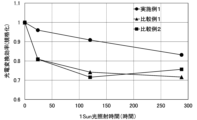
- 4 is a graph showing the relationship between the light irradiation time and the photoelectric conversion efficiency of the perovskite solar cell of Example 2.
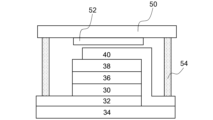
- FIG. 4 is a schematic cross-sectional view of the perovskite solar cell of Example 2.
- the metal oxide surface treatment method of the present application will be described based on embodiments and examples with reference to the drawings as appropriate.
- the metal oxide surface treatment method of the present application will be described as part of the method of manufacturing the perovskite solar cell of the present application.
- the metal oxide surface treatment apparatus and perovskite solar cell in the drawings are schematic representations of their configurations, they do not match the dimensional ratios of the actual metal oxide surface treatment apparatus and perovskite solar cell. .
- the same reference numerals may be given to the same members, and repeated explanations will be omitted as appropriate.
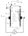
- FIG. 1 schematically shows a cross section of a metal oxide surface treatment apparatus 10 (hereinafter sometimes simply referred to as "surface treatment apparatus 10") according to an embodiment of the present application.
- the surface treatment apparatus 10 includes a processing vessel 12, an upper electrode 14, a lower electrode 16, a gas supply section 18, a high frequency power source 20, an exhaust port 22, an observation window 24, an emission detection section 26, and a recording section. 28.
- the surface treatment apparatus 10 treats the surface of the metal oxide 30 forming the electron transport layer of the object S to be treated with oxygen ions in oxygen plasma, which will be described later.
- the metals of the metal oxides are Al, Si, Sc with atomic number 21 to As with atomic number 33, Y with atomic number 38 to Sb with atomic number 51, and La with atomic number 57 to atomic number Up to Po of 84.
- the processing container 12 is made of a conductor material, such as an aluminum alloy, and is grounded.
- the upper electrode 14 is provided inside the processing container 12 and is made of a conductive material such as carbon.
- the lower electrode 16 is provided inside the processing container 12 so as to face the upper electrode 14 .
- the bottom electrode 16 is made of a conductive material such as carbon and is grounded.
- An object S to be processed is placed on the lower electrode 16 .
- the object S to be processed includes a transparent electrode layer 32 which is a constituent member of the perovskite solar cell C, and a layer of metal oxide 30 which is an electron transport layer formed on the transparent electrode layer 32 .
- a transparent electrode layer 32 and a layer of metal oxide 30 are laminated on a substrate 34 made of glass. Then, the object S to be processed is placed on the lower electrode 16 so that the layer of the metal oxide 30 is exposed.
- the gas supply unit 18 is connected to the processing container 12 and introduces oxygen gas G into the processing container 12 .
- a high frequency power supply 20 is electrically connected to the upper electrode 14 and the lower electrode 16 .
- the high-frequency power supply 20 applies a voltage having a frequency of 1 kHz or more and 40 kHz or less between the upper electrode 14 and the lower electrode 16, that is, supplies electric power.
- the oxygen gas G introduced between the upper electrode 14 and the lower electrode 16 from the gas supply section 18 is plasmatized to generate oxygen.
- Plasma PO is generated.
- oxygen plasma P 0 that is, oxygen radicals R 2 O and oxygen ions I 2 O can be efficiently generated. Further, by setting the frequency of the high-frequency power to 1 kHz or higher, the oxygen gas G can be turned into plasma.
- oxygen plasma is plasma generated from a gas containing 90 vol % or more of oxygen gas.
- the oxygen plasma is preferably a plasma generated from a gas containing 95 vol% or more of oxygen gas, more preferably a plasma generated from a gas containing 99 vol% or more of oxygen gas, and substantially composed of only oxygen gas. More preferably, the plasma is generated from a gas that
- Oxygen gas composed substantially only of oxygen is oxygen gas that does not contain impurities other than unavoidable impurities.
- oxygen gas supplied from a commercially available oxygen gas cylinder is oxygen gas substantially composed only of oxygen. Since the lower electrode 16 is grounded in the surface treatment apparatus 10, the oxygen ions I.sub.2O in the oxygen plasma P.sub.2O reach the surface of the metal oxide 30 considerably faster than the oxygen radicals R.sub.2O . The surface of the metal oxide 30 is modified by the oxygen ions I 2 O that have reached the surface of the metal oxide 30 .
- the exhaust port 22 discharges substances and oxygen radicals generated when the surface of the metal oxide 30 is treated with oxygen ions to the outside of the processing container 12 by an exhaust pump (not shown).
- Exhaust pumps include, for example, dry pumps, rotary pumps, or turbomolecular pumps that produce a high vacuum. In general, high vacuum increases the mean free path of plasma and improves plasma generation efficiency, so use of a turbo-molecular pump is preferred.
- the observation window 24 is a window for observing the inside of the processing container 12 from the outside, and is made of quartz, for example.
- the luminescence detector 26 detects luminescence within the processing container 12 .
- the light emission detector 26 is an optical fiber.
- the recording unit 28 is connected to the luminescence detection unit 26 to analyze and record luminescence within the processing container 12 .
- the recording unit 28 is a computer equipped with software for analyzing the type and intensity of light.
- the metal oxide surface treatment apparatus is a capacitively coupled plasma type metal oxide surface treatment apparatus, but instead of this, an inductively coupled plasma type metal oxide surface treatment apparatus is used. good too.
- An inductively coupled plasma type metal oxide surface treatment apparatus comprises: a dielectric processing container; an induction coil provided around the dielectric processing container; An electrode on which the object to be processed is installed so that the metal oxide layer of the object to be processed on which layers are laminated is exposed, a gas supply unit for introducing oxygen gas into the dielectric processing container, and a dielectric from the gas supply unit a high-frequency power supply having a frequency of 1 kHz or more and 40 kHz or less for supplying power to the induction coil so as to generate oxygen plasma from the oxygen gas introduced into the body treatment container.
- FIG. 2 schematically shows a cross section of the perovskite solar cell C.
- the perovskite solar cell C comprises a substrate 34, a transparent electrode layer 32, a layer of metal oxide 30 as an electron transport layer, a perovskite crystal layer 36 as a power generation layer, a hole transport layer 38, and an upper electrode layer 40. and , in that order.
- a perovskite crystal layer 36 is formed on the surface of the layer of metal oxide 30 .
- the perovskite solar cell C in addition to these constituent members, a diffusion prevention film provided on the light incident side of the substrate 34 and an interface between the metal oxide 30 layer as the electron transport layer and the perovskite crystal layer 36 are provided.
- An interface modification film or auxiliary layer, an interface modification film or auxiliary layer provided at the interface between the perovskite crystal layer 36 and the hole transport layer 38, or a sealing material and moisture for protecting the perovskite solar cell C from atmospheric moisture A getter material may be provided.
- the perovskite solar cell may be an inverted structure solar cell in which the electron transport layer and the hole transport layer in the perovskite solar cell C are exchanged. In this inverted structure solar cell, a structure in which the hole transport layer is a layer of metal oxide 30 and a perovskite crystal layer 36 is formed on the layer of metal oxide 30 can be adopted.
- the substrate 34 is a glass substrate
- the transparent electrode layer 32 is an FTO (fluorine-doped tin oxide) layer
- the metal oxide 30 layer is a tin oxide (SnO 2 ) layer composed of nanoparticles.
- the perovskite crystal layer 36 is Cs 0.05 (FA 0.89 MA 0.11 ) 0.95 Pb(I 0.89 Br 0.11 ) three layers (FA is formidinium, MA is methylamine (hereinafter the same) ),
- the hole-transporting layer 38 is a Spiro-OMeTAD (2,2′,7,7′-Tetrakis[N,N-di(4-methoxyphenyl)amino]-9,9′-spirobifluorene) layer
- the upper electrode layer 40 is a gold layer.
- a method for manufacturing a perovskite solar cell C according to an embodiment of the present application includes a transparent electrode layer, a metal oxide layer as an electron transport layer, a perovskite crystal layer as a power generation layer, a hole transport layer, and an upper electrode layer. , in this order, and the perovskite crystal layer is formed on the surface of the metal oxide layer.
- a method for manufacturing a perovskite solar cell according to another embodiment of the present application includes a transparent electrode layer, a metal oxide layer that is a hole transport layer, a perovskite crystal layer that is a power generation layer, an electron transport layer, and an upper electrode layer. are provided in this order, and the perovskite crystal layer is formed on the surface of the metal oxide layer.
- a method for manufacturing a perovskite solar cell according to each embodiment includes an oxygen plasma generation step, a metal oxide layer surface modification step, and a perovskite crystal layer formation step.
- the metal oxide 30 include titanium oxide and nickel oxide, in addition to tin oxide.
- perovskite crystals forming the perovskite crystal layer 36 in addition to Cs0.05 ( FA0.89MA0.11 ) 0.95Pb ( I0.89Br0.11 ) 3 , CH3NH3PbI3 and CH(NH 2 ) 2 PbI 3 and the like.
- the surface treatment apparatus 10 may be used, or another plasma treatment apparatus may be used.
- high-frequency power with a frequency of 1 kHz or more and 40 kHz or less is applied to generate oxygen plasma. More specifically, after cleaning the inside of the processing chamber 12 in advance with oxygen plasma, the object S to be processed is placed on the lower electrode 16, and the upper electrode 14 and the lower electrode are supplied from an oxygen tank connected to the gas supply unit 18. 16, the pressure in the processing container 12 is set to 50 Pa or more and 1200 Pa or less, and the power of 10 W is applied from the high frequency power supply 20 between the upper electrode 14 and the lower electrode 16 at a frequency of 1 kHz or more and 40 kHz or less. A high frequency power of 1000 W or more is supplied. Oxygen ions are efficiently generated by setting the power to 100 W or more and 1000 W or less.
- the supply of this high-frequency power converts the oxygen gas G into plasma, generating oxygen plasma PO .
- the pressure in the processing container 12 where the oxygen plasma P 2 O is generated is maintained at 1 Pa or more and 200 Pa or less, and the metal oxide layer surface modification step is performed. Oxygen ions are efficiently generated by setting the pressure to 1 Pa or more and 200 Pa or less.
- oxygen plasma P 2 O containing oxygen ions I 2 O was generated when the pressure in the processing container 12 was 500 Pa or less.
- this upper limit pressure varies depending on the surface treatment apparatus, the object to be treated, the concentration of the oxygen gas supplied into the treatment container, and the like. Therefore, as long as oxygen plasma P 2 O containing oxygen ions I 2 O can be generated, the pressure inside the processing container 12 is not particularly limited.
- the surface of the metal oxide 30 layer of the object S to be processed is irradiated with oxygen ions I 2 O in the oxygen plasma P 2 O to modify the surface of the metal oxide 30 layer.
- oxygen radicals R 2 O are not charged, they float between the upper electrode 14 and the lower electrode 16, and the surface of the metal oxide 30 is hardly irradiated.
- the surface of the metal oxide 30 after modification has substantially the same shape and a larger work function than the surface of the metal oxide 30 before modification.
- the surface of the metal oxide 30 is modified by the oxygen ions I 2 O , the surface of the metal oxide 30 is generated by plasma generated from a mixed gas of oxygen gas containing less than 90 vol % of oxygen gas and other gases. Processing time can be shortened compared to reforming.
- the surface modification can be performed in less than 40 seconds, whereas the treatment time is It takes 2 minutes or more for metal oxide surface modification using plasma of a mixed gas containing equal amounts of oxygen gas and argon gas, and 20 minutes or more for metal oxide surface modification by UV irradiation of ozone.
- the metal oxide surface treatment method of the embodiment of the present application includes the above oxygen plasma generation step and the above metal oxide surface modification step.
- the surface of the metal oxide is irradiated with oxygen ions in oxygen plasma to modify the surface of the metal oxide.
- This method for surface treatment of metal oxides is also a method for producing metal oxides whose surfaces have been modified.
- a perovskite crystal layer forming step a perovskite crystal layer is formed on the surface of the metal oxide layer modified in the metal oxide layer surface modification step.
- a perovskite crystal layer can be formed on the surface of the modified metal oxide layer by applying a perovskite crystal precursor to the surface of the modified metal oxide layer and drying it.
- a transparent electrode layer 32 is formed on a glass substrate 34 using a spin coating method, a sputtering method, a vacuum deposition method, a spray film forming method, a die coating method, a gravure printing method, a screen printing method, or the like.
- a metal oxide 30 is formed on the substrate, a hole transport layer 38 is formed on the perovskite crystal layer 36, and an upper electrode layer 40 is formed on the hole transport layer 38, respectively. These methods can also be employed when forming the perovskite crystal layer 36 on the layer of metal oxide 30 . The same is true for the reverse structure solar cell.
- a transparent electrode layer 32 is formed on a substrate 34 made of glass, and a metal oxide layer 30, which is a hole transport layer, is formed on the transparent electrode layer 32. , the perovskite crystal layer 36 on the metal oxide 30 layer, the electron transport layer on the perovskite crystal layer 36, and the upper electrode layer 40 on the electron transport layer.
- a plasma treatment apparatus (FEMTO (high-frequency power source frequency: 40 kHz, maximum power: 100 W), manufactured by Diener) having a structure as shown in FIG. 1 was used.
- a dry pump (ISP-50, manufactured by Anest Iwata Co., Ltd.) was connected to the exhaust port 22, and an oxygen cylinder (oxygen gas concentration: 99.5 vol%) was connected to the gas supply unit 18, respectively.
- Oxygen gas G was introduced into the processing container 12, and oxygen plasma P 2 O was generated so that the pressure in the processing container 12 was 10 different values ranging from 100 Pa to 1000 Pa.
- FIG. 3 shows an emission spectroscopic analysis chart at this time.
- Example 1 Surface Treatment of Tin Oxide with Oxygen Ions Surface treatment of tin oxide was performed using the plasma treatment apparatus of Reference Example. First, the FTO surface of glass with FTO (Nippon Sheet Glass Co., Ltd., NSG TEC 10) was dripped and spin-coated with a 15% by mass aqueous dispersion of tin (IV) oxide (Alfa Aesar) and dried at 150° C. for 1 hour. Thus, an object to be processed was obtained in which a glass substrate, an FTO layer as a transparent electrode layer, and a tin oxide layer as an electron transport layer were laminated in this order.
- this object to be processed was placed on the lower electrode so that the tin oxide faced the upper electrode.
- the pressure inside the processing container was reduced to 20 Pa or less by evacuation.
- oxygen gas was introduced into the processing chamber, the pressure in the processing chamber was maintained at 100 Pa, and high frequency power of 100 W was supplied between the upper electrode and the lower electrode to perform plasma cleaning for 30 seconds. rice field.
- the object to be processed was heated at 150°C for 1 hour.
- oxygen gas is introduced into the processing chamber, the pressure in the processing chamber is maintained at 100 Pa, high-frequency power of 100 W is supplied between the upper electrode and the lower electrode, and the oxygen gas is turned into plasma to generate oxygen plasma. let me This oxygen plasma contains oxygen radicals and oxygen ions as compared with the reference example. Then, the tin oxide was surface-treated for 30 seconds using oxygen ions in the oxygen plasma.
- Comparative Example 1 Surface Treatment of Tin Oxide with Ozone
- the surface treatment of tin oxide on the same object to be treated as in Example 1 was performed using a tabletop surface treatment apparatus (SSP16-110, Sen Special Light Source Co., Ltd.). First, this object to be processed was heated at 150° C. for 1 hour. Next, this object to be treated was placed in a desktop surface treatment apparatus. Then, the power of the UV light source was turned on, and the surface treatment of the tin oxide was performed for 20 minutes with ozone generated by the UV irradiation.
- SSP16-110 Sen Special Light Source Co., Ltd.
- Comparative Example 2 Surface Treatment of Tin Oxide with Oxygen Radicals Oxidation was carried out in the same manner as in Example 1, except that the pressure during oxygen plasma generation in Example 1 was changed to 1000 Pa and the surface treatment time was changed to 50 seconds. Tin surface treatment was performed. Oxygen plasma at a pressure of 1000 Pa contains only oxygen radicals compared to the reference example. Since the pressure inside the processing vessel is higher than in Example 1, the oxygen radicals descend quickly due to gravity, irradiate the object to be processed, and modify the surface of the tin oxide.
- Example 2 Evaluation of surface treatment of tin oxide (1) Work function of tin oxide By UPS (ultraviolet photoelectron spectroscopy), before surface treatment (untreated), Example 1, Comparative Example 1, and Comparative Example 2 The work function of the tin oxide surface after the surface treatment was calculated. The work functions of the tin oxide surfaces before the surface treatment and after the surface treatments of Example 1, Comparative Example 1, and Comparative Example 2 were 3.79 eV, 4.12 eV, 4.06 eV, and 4.04 eV, respectively. rice field. The surface treatment increased the work function of the tin oxide surface. Moreover, in Example 1, the work function of the tin oxide surface after the surface treatment was larger than in Comparative Examples 1 and 2. This is the effect of efficiently repairing oxygen defects in tin oxide with oxygen ions.
- UPS ultraviolet photoelectron spectroscopy
- the level of the conduction band of the perovskite crystal layer used in perovskite solar cells is generally between 3.5 eV and 4.5 eV, although it depends on the perovskite material.
- the work function of the metal oxide should be brought close to the level of the conduction band of the perovskite crystal layer, or the work function of the metal oxide is higher than the conduction band level of the perovskite crystal layer by about 0.2 eV. Since the work function of the tin oxide after the surface treatment of Example 1 was 4.12 eV, the electron extraction efficiency from this tin oxide to the perovskite crystal is high.
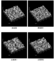
- the RMS of the tin oxide surface before the surface treatment and after the surface treatments of Example 1, Comparative Example 1, and Comparative Example 2 were 13.71 nm, 13.63 nm, 14.32 nm, and 12.72 nm, respectively. there were. From these similar RMS, it was found that the surface treatment did not cause damage that would change the surface shape of the tin oxide.
- Spiro-OMeTAD 61 mg of Spiro-OMeTAD and 10 mg of LiTFSI were dissolved in 0.7 mL of chlorobenzene, and 22 ⁇ L of 4-tert-butylpyridine was added to obtain a Spiro-OMeTAD precursor solution.
- This Spiro-OMeTAD precursor solution was applied to the surface of each of the Cs 0.05 (FA 0.89 MA 0.11 ) 0.95 Pb(I 0.89 Br 0.11 ) three layers obtained above at 3000 rpm. Spin coated for 30 seconds. Then, it was dried at 65° C. for 10 minutes to form a Spiro-OMeTAD layer.
- a gold layer having a thickness of 50 nm was deposited on the surface of these Spiro-OMeTAD layers using a vacuum deposition machine to obtain a solar cell member.
- FIG. 6 schematically shows a cross section of these perovskite solar cells.
- These perovskite solar cells were irradiated with simulated AM 1.5 sunlight (intensity 1000 W/m 2 ) using a solar simulator (OTENTO-SUN, manufactured by Spectroscopic Instruments Co., Ltd.).
- a short-circuit current density, an open-circuit voltage, a fill factor, and a photoelectric conversion efficiency were obtained from a curve plotting a current-voltage relationship using a source meter (Keithley 2400, manufactured by Keithley Instruments (hereinafter the same)). Table 1 shows the results.
- the perovskite solar cell manufactured from the processed material obtained in Example 1 had a higher open-circuit voltage than the perovskite solar cell manufactured from the processed material obtained in Comparative Example 1. .
- the light durability of the perovskite solar cells produced from the objects to be treated obtained in Example 1, Comparative Example 1, and Comparative Example 2 was evaluated.
- these perovskite solar cells were continuously irradiated with AM1.5 simulated sunlight (intensity 1000 W/m 2 ) at 25° C. and 30% humidity.
- the photoelectric conversion efficiency was obtained from a curve obtained by plotting the current-voltage relationship with a source meter at predetermined time intervals, and the ratio between the obtained photoelectric conversion efficiency and the initial photoelectric conversion efficiency was calculated. The results are shown in FIG. As shown in FIG.
- the perovskite solar cell manufactured from the object to be processed obtained in Example 1 had higher light durability than other perovskite solar cells. This is because the oxygen deficiency on the surface of the tin oxide was repaired by the surface treatment of the tin oxide in Example 1, and the light durability centering on the visible light region was improved.
- Example 3 Surface Treatment of Titanium Oxide with Oxygen Ions
- a titanium diisopropoxide acetylacetonate solution (Aldrich Co.) was diluted with ethanol so that the concentration of this titanium compound was 6% by mass to prepare a titanium oxide precursor solution. got In an environment of 400° C., this titanium oxide precursor liquid was sprayed onto the FTO surface of a glass with FTO (NSG TEC 10, Nippon Sheet Glass Co., Ltd.) using an air brush, and dried at 500° C. for 10 minutes to form a glass substrate, An object to be treated was obtained in which an FTO layer and a titanium oxide layer used as an electron transport layer of a regular structure perovskite solar cell were laminated in this order. In the same manner as in Example 1, the titanium oxide surface of this object to be treated was treated with oxygen ions.
- Comparative Example 3 Surface Treatment of Titanium Oxide with Ozone An object to be treated having a layer of titanium oxide was obtained in the same manner as in Example 3, and the surface of the titanium oxide of the object to be treated was treated with ozone in the same manner as in Comparative Example 1. processed.
- Comparative Example 4 Surface Treatment of Titanium Oxide with Oxygen Radicals An object to be treated having a layer of titanium oxide was obtained in the same manner as in Example 3, and the titanium oxide surface of the object to be treated was treated in the same manner as in Comparative Example 2. Oxygen radical treatment.
- Example 4 Evaluation of surface treatment of titanium oxide
- titanium oxide before surface treatment (untreated) and after surface treatment of Example 3, Comparative Example 3, and Comparative Example 4 We calculated the work function of the surface of The work functions of the titanium oxide surfaces before the surface treatment and after the surface treatments of Example 2, Comparative Example 3, and Comparative Example 4 were 3.87 eV, 4.12 eV, 4.27 eV, and 4.34 eV, respectively. rice field.
- the surface treatment increased the work function of the titanium oxide surface.
- the work function of the titanium oxide surface after the surface treatment was larger than in Comparative Examples 3 and 4. This is the effect of efficiently repairing oxygen defects in titanium oxide with oxygen ions.
- the work function of the titanium oxide after the surface treatment in Example 3 was 4.12 eV, so the electron extraction efficiency from this titanium oxide to the perovskite crystal is high.
- Example 5 Surface Treatment of Nickel Oxide with Oxygen Ions
- Nickel oxide used as a hole-transporting layer for an inverse structure perovskite solar cell was performed.
- FTO surface of glass with FTO Nippon Sheet Glass Co., Ltd., NSG TEC 10
- AVANTAMA 2.5 mass% ethanol dispersion of nickel oxide
- an object to be processed in which the glass substrate, the FTO layer, and the nickel oxide layer were laminated in this order was obtained.
- Comparative Example 5 Surface Treatment of Nickel Oxide with Ozone An object to be treated having a nickel oxide layer was obtained in the same manner as in Example 5, and the nickel oxide surface of the object to be treated was treated with ozone in the same manner as in Comparative Example 1. processed.
- Comparative Example 6 Surface Treatment of Nickel Oxide with Oxygen Radicals An object to be treated having a layer of nickel oxide was obtained in the same manner as in Example 5, and the nickel oxide surface of the object to be treated was treated in the same manner as in Comparative Example 2. Oxygen radical treatment.
- Example 6 Evaluation of surface treatment of nickel oxide
- nickel oxide before surface treatment (untreated) and after surface treatment of Example 5, Comparative Example 5, and Comparative Example 6 We calculated the work function of the surface of The work functions of the nickel oxide surfaces before the surface treatment and after the surface treatments of Example 5, Comparative Example 5, and Comparative Example 6 were 5.16 eV, 5.43 eV, 5.59 eV, and 5.52 eV, respectively. rice field.
- the surface treatment increased the work function of the nickel oxide surface.
- the valence band level of the perovskite crystal layer used in perovskite solar cells depends on the perovskite material, but is generally between 4.5 eV and 6.0 eV. be. In order to reduce the interfacial resistance between the perovskite crystal and the metal oxide and improve the hole extraction efficiency, it is preferable to bring the work function of the metal oxide closer to the level of the valence band of the perovskite crystal layer. Since the work function of the nickel oxide after the surface treatment of Example 5 was 5.43 eV, the hole extraction efficiency from this nickel oxide to the perovskite crystal is high.
Abstract
In order to treat, in a short time, the surface of a metal oxide used in an electron transport layer or the like of a Perovskite solar cell, this method for treating the surface of a metal oxide 30 is provided with an oxygen plasma generation step for supplying high-frequency electric power having a frequency of 1-40 kHz to generate an oxygen plasma PO, and a metal oxide surface modification step for irradiating the surface of the metal oxide 30 with oxygen ions IO in the oxygen plasma PO to modify the surface of the metal oxide 30.
Description
本願は、酸素プラズマ中の酸素イオンを用いて、ペロブスカイト太陽電池の電子輸送層などに使用される金属酸化物の表面を処理する方法に関する。また、本願は、この金属酸化物の表面を処理する方法を含むペロブスカイト太陽電池の製造方法に関する。また、本願は、この金属酸化物の表面を処理する方法を行うのに適した金属酸化物表面処理装置に関する。
This application relates to a method of treating the surface of metal oxides used in the electron transport layer of perovskite solar cells, etc., using oxygen ions in oxygen plasma. The present application also relates to a method of manufacturing a perovskite solar cell, including a method of treating the surface of this metal oxide. The present application also relates to a metal oxide surface treatment apparatus suitable for carrying out this method of treating the surface of metal oxides.
近年、透明電極層、電子輸送層、ペロブスカイト結晶層、正孔輸送層、および電極層をこの順序で備えるペロブスカイト太陽電池が注目されている。ペロブスカイト太陽電池の電子輸送層を構成する金属酸化物とペロブスカイト結晶層との密着性を向上させるため、および界面抵抗を下げるため、金属酸化物の表面の改質処理が行われている。特許文献1には、アルゴンガスと酸素ガスとの混合ガスプラズマを用いて、ITO基板の表面を改質処理する方法が記載されている。
In recent years, attention has been paid to perovskite solar cells that comprise a transparent electrode layer, an electron transport layer, a perovskite crystal layer, a hole transport layer, and an electrode layer in this order. In order to improve the adhesion between the metal oxide and the perovskite crystal layer that constitute the electron transport layer of the perovskite solar cell and to reduce the interfacial resistance, the surface of the metal oxide is subjected to modification treatment. Patent Document 1 describes a method of modifying the surface of an ITO substrate using mixed gas plasma of argon gas and oxygen gas.
特許文献1では、2分間かけてITO基板表面の改質処理を行っている。一方、プラズマ処理装置が不要なオゾンのUV照射によって、ペロブスカイト太陽電池の電子輸送層を構成する金属酸化物の表面を改質する方法も知られている。しかし、このオゾンのUV照射によっても、金属酸化物の表面の改質に約20分間要する。ペロブスカイト太陽電池の量産時のコストダウンのためには、金属酸化物の表面処理速度の向上が求められている。
In Patent Document 1, the ITO substrate surface is modified for 2 minutes. On the other hand, there is also known a method of modifying the surface of the metal oxide that constitutes the electron transport layer of the perovskite solar cell by UV irradiation of ozone, which does not require a plasma treatment apparatus. However, even with this UV irradiation of ozone, it takes about 20 minutes to modify the surface of the metal oxide. In order to reduce the cost of mass-producing perovskite solar cells, it is necessary to improve the surface treatment speed of metal oxides.
本願は、このような事情に鑑みてなされたものであり、ペロブスカイト太陽電池の電子輸送層などとして使用される金属酸化物の表面を短時間で処理することを課題とする。
The present application has been made in view of such circumstances, and the object of the present application is to treat the surface of metal oxides used as the electron transport layer of perovskite solar cells in a short period of time.
本願の金属酸化物の表面処理方法は、周波数1kHz以上40kHz以下の高周波電力を供給して、酸素プラズマを生成する酸素プラズマ生成工程と、金属酸化物の表面に酸素プラズマ中の酸素イオンを照射して、金属酸化物の表面を改質する金属酸化物表面改質工程と、を有する。
The metal oxide surface treatment method of the present application comprises an oxygen plasma generation step of supplying high-frequency power with a frequency of 1 kHz or more and 40 kHz or less to generate oxygen plasma, and irradiating the surface of the metal oxide with oxygen ions in the oxygen plasma. and a metal oxide surface modification step of modifying the surface of the metal oxide.
本願のペロブスカイト太陽電池の製造方法は、透明電極層、電子輸送層または正孔輸送層である金属酸化物層と、発電層であるペロブスカイト結晶層と、正孔輸送層または電子輸送層と、上部電極層とを、この順序で備え、金属酸化物層の表面にペロブスカイト結晶層が形成されているペロブスカイト太陽電池の製造方法であって、周波数1kHz以上40kHz以下の高周波電力を印加して、酸素プラズマを生成する酸素プラズマ生成工程と、透明電極層および金属酸化物層を備える被処理体の金属酸化物層の表面に、酸素プラズマ中の酸素イオンを照射して、金属酸化物層の表面を改質する金属酸化物層表面改質工程と、金属酸化物層表面改質工程によって改質された金属酸化物層の表面に、ペロブスカイト結晶層を形成するペロブスカイト結晶層形成工程と、を有する。
A method for producing a perovskite solar cell of the present application comprises: a transparent electrode layer, a metal oxide layer that is an electron transport layer or a hole transport layer; a perovskite crystal layer that is a power generation layer; a hole transport layer or an electron transport layer; and an electrode layer in this order, and a perovskite crystal layer is formed on the surface of the metal oxide layer, wherein high-frequency power with a frequency of 1 kHz or more and 40 kHz or less is applied to generate oxygen plasma. and irradiating oxygen ions in the oxygen plasma to the surface of the metal oxide layer of the object to be treated, which includes the transparent electrode layer and the metal oxide layer, to modify the surface of the metal oxide layer. and a perovskite crystal layer forming step of forming a perovskite crystal layer on the surface of the metal oxide layer modified by the metal oxide layer surface modification step.
本願の一態様の金属酸化物表面処理装置は、処理容器と、処理容器内に設けられた上部電極と、接地されるように処理容器内に設けられ、透明電極層および金属酸化物層が積層されている被処理体の金属酸化物層が露出するように被処理体が設置される下部電極と、酸素ガスを処理容器内に導入するガス供給部と、ガス供給部から上部電極と下部電極との間に導入された酸素ガスから酸素プラズマが生成するように、上部電極と下部電極との間に電力を供給する周波数1kHz以上40kHz以下の高周波電源と、を有する。
A metal oxide surface treatment apparatus according to one aspect of the present application includes a processing container, an upper electrode provided in the processing container, and a transparent electrode layer and a metal oxide layer provided in the processing container so as to be grounded. a lower electrode on which the object to be processed is placed so as to expose the metal oxide layer of the object to be processed, a gas supply unit for introducing oxygen gas into the processing container, and the upper electrode and the lower electrode from the gas supply unit a high-frequency power source with a frequency of 1 kHz or more and 40 kHz or less for supplying power between the upper electrode and the lower electrode so that oxygen plasma is generated from the oxygen gas introduced between.
本願の他の態様の金属酸化物表面処理装置は、誘電体処理容器と、誘電体処理容器の周囲に設けられた誘導コイルと、誘電体処理容器内に設けられ、透明電極層および金属酸化物層が積層されている被処理体の金属酸化物層が露出するように被処理体が設置される電極と、酸素ガスを誘電体処理容器内に導入するガス供給部と、ガス供給部から誘電体処理容器内に導入された酸素ガスから酸素プラズマが生成するように、誘導コイルに電力を供給する周波数1kHz以上40kHz以下の高周波電源と、を有する。
A metal oxide surface treatment apparatus according to another aspect of the present application includes a dielectric processing container, an induction coil provided around the dielectric processing container, and a transparent electrode layer and a metal oxide provided in the dielectric processing container. An electrode on which the object to be processed is installed so that the metal oxide layer of the object to be processed on which layers are laminated is exposed, a gas supply unit for introducing oxygen gas into the dielectric processing container, and a dielectric from the gas supply unit a high-frequency power supply with a frequency of 1 kHz or more and 40 kHz or less for supplying power to the induction coil so as to generate oxygen plasma from the oxygen gas introduced into the body treatment container.
本願の金属酸化物の表面処理方法は、周波数1kHz以上40kHz以下の高周波電力による酸素プラズマの酸素イオンを金属酸化物の表面に照射する。このため、本願の金属酸化物の表面処理方法によれば、金属酸化物の表面を短時間で処理できる。また、本願のペロブスカイト太陽電池の製造方法は、周波数1kHz以上40kHz以下の高周波電力による酸素プラズマの酸素イオンを金属酸化物層の表面に照射する過程を備えている。このため、本願のペロブスカイト太陽電池の製造方法によれば、ペロブスカイト太陽電池を短時間で製造できる。本願の金属酸化物表面処理装置は、周波数1kHz以上40kHz以下の高周波電力による酸素プラズマの酸素イオンを金属酸化物層の表面に照射するように構成されている。このため、本願の金属酸化物表面処理装置によれば、金属酸化物層の表面を短時間で処理できる。
In the metal oxide surface treatment method of the present application, the surface of the metal oxide is irradiated with oxygen ions of oxygen plasma generated by high-frequency power with a frequency of 1 kHz or more and 40 kHz or less. Therefore, according to the metal oxide surface treatment method of the present application, the surface of the metal oxide can be treated in a short time. Further, the method of manufacturing a perovskite solar cell of the present application includes a step of irradiating the surface of the metal oxide layer with oxygen ions of oxygen plasma generated by high-frequency power having a frequency of 1 kHz or more and 40 kHz or less. Therefore, according to the method for manufacturing a perovskite solar cell of the present application, a perovskite solar cell can be manufactured in a short time. The metal oxide surface treatment apparatus of the present application is configured to irradiate the surface of the metal oxide layer with oxygen ions of oxygen plasma generated by high-frequency power having a frequency of 1 kHz to 40 kHz. Therefore, according to the metal oxide surface treatment apparatus of the present application, the surface of the metal oxide layer can be treated in a short time.
以下、図面を適宜参照しながら、本願の金属酸化物の表面処理方法、本願のペロブスカイト太陽電池の製造方法、および本願の金属酸化物表面処理装置について、実施形態と実施例に基づいて説明する。なお、本願の金属酸化物の表面処理方法は、本願のペロブスカイト太陽電池の製造方法の一部として説明される。また、図面上の金属酸化物表面処理装置およびペロブスカイト太陽電池は、その構成を模式的に表したものであるから、実物の金属酸化物表面処理装置およびペロブスカイト太陽電池の寸法比と一致していない。同一部材には同一符号を付与することがあり、重複説明は適宜省略する。
Hereinafter, the metal oxide surface treatment method of the present application, the perovskite solar cell manufacturing method of the present application, and the metal oxide surface treatment apparatus of the present application will be described based on embodiments and examples with reference to the drawings as appropriate. The metal oxide surface treatment method of the present application will be described as part of the method of manufacturing the perovskite solar cell of the present application. Also, since the metal oxide surface treatment apparatus and perovskite solar cell in the drawings are schematic representations of their configurations, they do not match the dimensional ratios of the actual metal oxide surface treatment apparatus and perovskite solar cell. . The same reference numerals may be given to the same members, and repeated explanations will be omitted as appropriate.
図1は、本願の実施形態の金属酸化物表面処理装置10(以下単に「表面処理装置10」ということがある)の断面を模式的に示している。表面処理装置10は、処理容器12と、上部電極14と、下部電極16と、ガス供給部18と、高周波電源20と、排気口22と、観察窓24と、発光検出部26と、記録部28とを備えている。表面処理装置10は、被処理体Sの電子輸送層を構成する金属酸化物30の表面を、後述する酸素プラズマ中の酸素イオンによって処理する。本願において、金属酸化物の金属とは、Al、Si、原子番号21のScから原子番号33のAsまで、原子番号38のYから原子番号51のSbまで、および原子番号57のLaから原子番号84のPoまでをいう。
FIG. 1 schematically shows a cross section of a metal oxide surface treatment apparatus 10 (hereinafter sometimes simply referred to as "surface treatment apparatus 10") according to an embodiment of the present application. The surface treatment apparatus 10 includes a processing vessel 12, an upper electrode 14, a lower electrode 16, a gas supply section 18, a high frequency power source 20, an exhaust port 22, an observation window 24, an emission detection section 26, and a recording section. 28. The surface treatment apparatus 10 treats the surface of the metal oxide 30 forming the electron transport layer of the object S to be treated with oxygen ions in oxygen plasma, which will be described later. In this application, the metals of the metal oxides are Al, Si, Sc with atomic number 21 to As with atomic number 33, Y with atomic number 38 to Sb with atomic number 51, and La with atomic number 57 to atomic number Up to Po of 84.
処理容器12は、導体材料、例えばアルミニウム合金から構成されており、接地されている。上部電極14は、処理容器12内に設けられており、導電性材料、例えば炭素から構成されている。下部電極16は、上部電極14と対向するように処理容器12内に設けられている。下部電極16は、導電性材料、例えば炭素から構成されており、接地されている。被処理体Sは下部電極16上に設置される。被処理体Sは、ペロブスカイト太陽電池Cの構成部材の透明電極層32と、透明電極層32の上に形成された電子輸送層である金属酸化物30の層とを備えている。本実施形態では、ガラスから構成されている基板34上に透明電極層32と金属酸化物30の層とが積層されている。そして、金属酸化物30の層が露出するように、被処理体Sが下部電極16上に設置される。
The processing container 12 is made of a conductor material, such as an aluminum alloy, and is grounded. The upper electrode 14 is provided inside the processing container 12 and is made of a conductive material such as carbon. The lower electrode 16 is provided inside the processing container 12 so as to face the upper electrode 14 . The bottom electrode 16 is made of a conductive material such as carbon and is grounded. An object S to be processed is placed on the lower electrode 16 . The object S to be processed includes a transparent electrode layer 32 which is a constituent member of the perovskite solar cell C, and a layer of metal oxide 30 which is an electron transport layer formed on the transparent electrode layer 32 . In this embodiment, a transparent electrode layer 32 and a layer of metal oxide 30 are laminated on a substrate 34 made of glass. Then, the object S to be processed is placed on the lower electrode 16 so that the layer of the metal oxide 30 is exposed.
ガス供給部18は、処理容器12に接続されており、処理容器12内に酸素ガスGを導入する。高周波電源20は、上部電極14および下部電極16に電気的に接続されている。高周波電源20は、上部電極14と下部電極16との間に周波数1kHz以上40kHz以下の電圧を印加、すなわち電力を供給する。高周波電源20から上部電極14と下部電極16との間に電力が供給されると、ガス供給部18から上部電極14と下部電極16との間に導入された酸素ガスGがプラズマ化され、酸素プラズマPOが生成する。
The gas supply unit 18 is connected to the processing container 12 and introduces oxygen gas G into the processing container 12 . A high frequency power supply 20 is electrically connected to the upper electrode 14 and the lower electrode 16 . The high-frequency power supply 20 applies a voltage having a frequency of 1 kHz or more and 40 kHz or less between the upper electrode 14 and the lower electrode 16, that is, supplies electric power. When electric power is supplied between the upper electrode 14 and the lower electrode 16 from the high-frequency power source 20, the oxygen gas G introduced between the upper electrode 14 and the lower electrode 16 from the gas supply section 18 is plasmatized to generate oxygen. Plasma PO is generated.
高周波電力の周波数を40kHz以下とすることで、酸素プラズマPO、すなわち酸素ラジカルROと酸素イオンIOを効率よく生成できる。また、高周波電力の周波数を1kHz以上とすることで、酸素ガスGのプラズマ化が可能となる。なお、酸素プラズマとは、酸素ガスを90vol%以上含むガスから生成するプラズマである。酸素プラズマは、酸素ガスを95vol%以上含むガスから生成するプラズマであることが好ましく、酸素ガスを99vol%以上含むガスから生成するプラズマであることがより好ましく、実質的に酸素ガスのみから構成されるガスから生成するプラズマであることがさらに好ましい。
By setting the frequency of the high-frequency power to 40 kHz or less, oxygen plasma P 0 , that is, oxygen radicals R 2 O and oxygen ions I 2 O can be efficiently generated. Further, by setting the frequency of the high-frequency power to 1 kHz or higher, the oxygen gas G can be turned into plasma. Note that oxygen plasma is plasma generated from a gas containing 90 vol % or more of oxygen gas. The oxygen plasma is preferably a plasma generated from a gas containing 95 vol% or more of oxygen gas, more preferably a plasma generated from a gas containing 99 vol% or more of oxygen gas, and substantially composed of only oxygen gas. More preferably, the plasma is generated from a gas that
実質的に酸素のみから構成される酸素ガスとは、不可避的な不純物以外の不純物を含まない酸素ガスである。例えば、市販の酸素ガスボンベから供給される酸素ガスは、実質的に酸素のみから構成される酸素ガスである。表面処理装置10では、下部電極16が接地されているので、酸素プラズマPO中の酸素イオンIOは、酸素ラジカルROと比べて、かなり速く金属酸化物30の表面に到達する。金属酸化物30の表面に到達した酸素イオンIOによって、金属酸化物30の表面が改質される。
Oxygen gas composed substantially only of oxygen is oxygen gas that does not contain impurities other than unavoidable impurities. For example, oxygen gas supplied from a commercially available oxygen gas cylinder is oxygen gas substantially composed only of oxygen. Since the lower electrode 16 is grounded in the surface treatment apparatus 10, the oxygen ions I.sub.2O in the oxygen plasma P.sub.2O reach the surface of the metal oxide 30 considerably faster than the oxygen radicals R.sub.2O . The surface of the metal oxide 30 is modified by the oxygen ions I 2 O that have reached the surface of the metal oxide 30 .
排気口22は、排気ポンプ(不図示)によって、金属酸化物30の表面が酸素イオンで処理されたときに生成する物質および酸素ラジカルなどを処理容器12の外に排出する。排気ポンプとしては、例えば、ドライポンプ、ロータリーポンプ、または高真空を生じるターボ分子ポンプが挙げられる。一般的に高真空の方がプラズマの平均自由行程が増え、プラズマ生成効率が上がるため、ターボ分子ポンプの使用が好ましい。
The exhaust port 22 discharges substances and oxygen radicals generated when the surface of the metal oxide 30 is treated with oxygen ions to the outside of the processing container 12 by an exhaust pump (not shown). Exhaust pumps include, for example, dry pumps, rotary pumps, or turbomolecular pumps that produce a high vacuum. In general, high vacuum increases the mean free path of plasma and improves plasma generation efficiency, so use of a turbo-molecular pump is preferred.
観察窓24は、処理容器12内を外から観察するための窓であり、例えば石英から構成されている。発光検出部26は処理容器12内の発光を検出する。本実施形態では、発光検出部26は光ファイバーである。記録部28は、発光検出部26に接続され、処理容器12内の発光を解析し、記録する。本実施形態では、記録部28は、光の種類と強度などを解析するソフトウェアを搭載したコンピューターである。
The observation window 24 is a window for observing the inside of the processing container 12 from the outside, and is made of quartz, for example. The luminescence detector 26 detects luminescence within the processing container 12 . In this embodiment, the light emission detector 26 is an optical fiber. The recording unit 28 is connected to the luminescence detection unit 26 to analyze and record luminescence within the processing container 12 . In this embodiment, the recording unit 28 is a computer equipped with software for analyzing the type and intensity of light.
金属酸化物表面処理装置は、本実施形態では、容量結合型プラズマ方式の金属酸化物表面処理装置であったが、これに代えて、誘導結合型プラズマ方式の金属酸化物表面処理装置であってもよい。誘導結合型プラズマ方式の金属酸化物表面処理装置は、誘電体処理容器と、誘電体処理容器の周囲に設けられた誘導コイルと、誘電体処理容器内に設けられ、透明電極層および金属酸化物層が積層されている被処理体の金属酸化物層が露出するように被処理体が設置される電極と、酸素ガスを誘電体処理容器内に導入するガス供給部と、ガス供給部から誘電体処理容器内に導入された酸素ガスから酸素プラズマが生成するように、誘導コイルに電力を供給する周波数1kHz以上40kHz以下の高周波電源と、を備えている。
In this embodiment, the metal oxide surface treatment apparatus is a capacitively coupled plasma type metal oxide surface treatment apparatus, but instead of this, an inductively coupled plasma type metal oxide surface treatment apparatus is used. good too. An inductively coupled plasma type metal oxide surface treatment apparatus comprises: a dielectric processing container; an induction coil provided around the dielectric processing container; An electrode on which the object to be processed is installed so that the metal oxide layer of the object to be processed on which layers are laminated is exposed, a gas supply unit for introducing oxygen gas into the dielectric processing container, and a dielectric from the gas supply unit a high-frequency power supply having a frequency of 1 kHz or more and 40 kHz or less for supplying power to the induction coil so as to generate oxygen plasma from the oxygen gas introduced into the body treatment container.
表面処理装置10を用いたペロブスカイト太陽電池Cの製造方法について以下で説明する。図2は、ペロブスカイト太陽電池Cの断面を模式的に示している。ペロブスカイト太陽電池Cは、基板34と、透明電極層32と、電子輸送層である金属酸化物30の層と、発電層であるペロブスカイト結晶層36と、正孔輸送層38と、上部電極層40とを、この順序で備えている。そして、金属酸化物30の層の表面にペロブスカイト結晶層36が形成されている。
A method for manufacturing the perovskite solar cell C using the surface treatment apparatus 10 will be described below. FIG. 2 schematically shows a cross section of the perovskite solar cell C. As shown in FIG. The perovskite solar cell C comprises a substrate 34, a transparent electrode layer 32, a layer of metal oxide 30 as an electron transport layer, a perovskite crystal layer 36 as a power generation layer, a hole transport layer 38, and an upper electrode layer 40. and , in that order. A perovskite crystal layer 36 is formed on the surface of the layer of metal oxide 30 .
ペロブスカイト太陽電池Cは、これらの構成部材以外に、基板34の光入射側に設けられた拡散防止膜、電子輸送層である金属酸化物30の層とペロブスカイト結晶層36との界面に設けられた界面修飾膜もしくは補助層、ペロブスカイト結晶層36と正孔輸送層38との界面に設けられた界面修飾膜もしくは補助層、または、ペロブスカイト太陽電池Cを大気中の水分から保護する封止材および水分ゲッター材を備えていてもよい。また、ペロブスカイト太陽電池は、ペロブスカイト太陽電池Cでの電子輸送層と正孔輸送層とが入れ替わった逆型構造太陽電池であってもよい。この逆型構造太陽電池では、正孔輸送層が金属酸化物30の層であり、この金属酸化物30の層上にペロブスカイト結晶層36が形成された構造が採用されることができる。
In the perovskite solar cell C, in addition to these constituent members, a diffusion prevention film provided on the light incident side of the substrate 34 and an interface between the metal oxide 30 layer as the electron transport layer and the perovskite crystal layer 36 are provided. An interface modification film or auxiliary layer, an interface modification film or auxiliary layer provided at the interface between the perovskite crystal layer 36 and the hole transport layer 38, or a sealing material and moisture for protecting the perovskite solar cell C from atmospheric moisture A getter material may be provided. Moreover, the perovskite solar cell may be an inverted structure solar cell in which the electron transport layer and the hole transport layer in the perovskite solar cell C are exchanged. In this inverted structure solar cell, a structure in which the hole transport layer is a layer of metal oxide 30 and a perovskite crystal layer 36 is formed on the layer of metal oxide 30 can be adopted.
本実施形態では、基板34がガラス基板であり、透明電極層32がFTO(Fluorine-doped tin oxide)層であり、金属酸化物30の層がナノ粒子から構成される酸化スズ(SnO2)層であり、ペロブスカイト結晶層36がCs0.05(FA0.89MA0.11)0.95Pb(I0.89Br0.11)3層(FAはformamidinium、MAはMethylamine(以下同じ))であり、正孔輸送層38がSpiro-OMeTAD(2,2’,7,7’-Tetrakis[N,N-di(4-methoxyphenyl)amino]-9,9’-spirobifluorene)層であり、上部電極層40が金層である。
In this embodiment, the substrate 34 is a glass substrate, the transparent electrode layer 32 is an FTO (fluorine-doped tin oxide) layer, and the metal oxide 30 layer is a tin oxide (SnO 2 ) layer composed of nanoparticles. and the perovskite crystal layer 36 is Cs 0.05 (FA 0.89 MA 0.11 ) 0.95 Pb(I 0.89 Br 0.11 ) three layers (FA is formidinium, MA is methylamine (hereinafter the same) ), the hole-transporting layer 38 is a Spiro-OMeTAD (2,2′,7,7′-Tetrakis[N,N-di(4-methoxyphenyl)amino]-9,9′-spirobifluorene) layer, The upper electrode layer 40 is a gold layer.
本願の実施形態のペロブスカイト太陽電池Cの製造方法は、透明電極層と、電子輸送層である金属酸化物層と、発電層であるペロブスカイト結晶層と、正孔輸送層と、上部電極層とを、この順序で備え、前記金属酸化物層の表面に前記ペロブスカイト結晶層が形成されているペロブスカイト太陽電池の製造方法である。本願の他の実施形態のペロブスカイト太陽電池の製造方法は、透明電極層と、正孔輸送層である金属酸化物層と、発電層であるペロブスカイト結晶層と、電子輸送層と、上部電極層とを、この順序で備え、前記金属酸化物層の表面に前記ペロブスカイト結晶層が形成されているペロブスカイト太陽電池の製造方法である。
A method for manufacturing a perovskite solar cell C according to an embodiment of the present application includes a transparent electrode layer, a metal oxide layer as an electron transport layer, a perovskite crystal layer as a power generation layer, a hole transport layer, and an upper electrode layer. , in this order, and the perovskite crystal layer is formed on the surface of the metal oxide layer. A method for manufacturing a perovskite solar cell according to another embodiment of the present application includes a transparent electrode layer, a metal oxide layer that is a hole transport layer, a perovskite crystal layer that is a power generation layer, an electron transport layer, and an upper electrode layer. are provided in this order, and the perovskite crystal layer is formed on the surface of the metal oxide layer.
各実施形態のペロブスカイト太陽電池の製造方法は、酸素プラズマ生成工程と、金属酸化物層表面改質工程と、ペロブスカイト結晶層形成工程とを備えている。金属酸化物30としては、酸化スズ以外に、酸化チタンおよび酸化ニッケルなどが挙げられる。ペロブスカイト結晶層36を構成するペロブスカイト結晶としては、Cs0.05(FA0.89MA0.11)0.95Pb(I0.89Br0.11)3以外に、CH3NH3PbI3およびCH(NH2)2PbI3などが挙げられる。なお、各実施形態のペロブスカイト太陽電池の製造方法では、表面処理装置10を使用してもよいし、他のプラズマ処理装置を使用してもよい。
A method for manufacturing a perovskite solar cell according to each embodiment includes an oxygen plasma generation step, a metal oxide layer surface modification step, and a perovskite crystal layer formation step. Examples of the metal oxide 30 include titanium oxide and nickel oxide, in addition to tin oxide. As perovskite crystals forming the perovskite crystal layer 36, in addition to Cs0.05 ( FA0.89MA0.11 ) 0.95Pb ( I0.89Br0.11 ) 3 , CH3NH3PbI3 and CH(NH 2 ) 2 PbI 3 and the like. In addition, in the method for manufacturing a perovskite solar cell according to each embodiment, the surface treatment apparatus 10 may be used, or another plasma treatment apparatus may be used.
酸素プラズマ生成工程では、周波数1kHz以上40kHz以下の高周波電力を印加して、酸素プラズマを生成する。より具体的には、事前に酸素プラズマによって処理容器12内を洗浄した後、被処理体Sを下部電極16上に設置し、ガス供給部18に接続された酸素ボンベから上部電極14と下部電極16との間に酸素ガスGを導入し、処理容器12内の圧力を50Pa以上1200Pa以下にして、高周波電源20から上部電極14と下部電極16との間に、周波数1kHz以上40kHz以下で電力10W以上1000W以下の高周波電力を供給する。電力を100W以上1000W以下とすることで酸素イオンが効率的に生成される。
In the oxygen plasma generation step, high-frequency power with a frequency of 1 kHz or more and 40 kHz or less is applied to generate oxygen plasma. More specifically, after cleaning the inside of the processing chamber 12 in advance with oxygen plasma, the object S to be processed is placed on the lower electrode 16, and the upper electrode 14 and the lower electrode are supplied from an oxygen tank connected to the gas supply unit 18. 16, the pressure in the processing container 12 is set to 50 Pa or more and 1200 Pa or less, and the power of 10 W is applied from the high frequency power supply 20 between the upper electrode 14 and the lower electrode 16 at a frequency of 1 kHz or more and 40 kHz or less. A high frequency power of 1000 W or more is supplied. Oxygen ions are efficiently generated by setting the power to 100 W or more and 1000 W or less.
この高周波電力の供給によって、酸素ガスGがプラズマ化されて、酸素プラズマPOが生成する。酸素プラズマPOが生成している処理容器12内の圧力を1Pa以上200Pa以下に維持し、金属酸化物層表面改質工程を行う。圧力を1Pa以上200Pa以下とすることで酸素イオンが効率的に生成される。後述する実施例では、処理容器12内の圧力が500Pa以下のときに、酸素イオンIOを含む酸素プラズマPOが生成した。しかし、この上限圧力は、表面処理装置、被処理体、および処理容器内に供給される酸素ガスの濃度などによって変化する。したがって、酸素イオンIOを含む酸素プラズマPOが生成できれば、処理容器12内の圧力は特に制限されない。
The supply of this high-frequency power converts the oxygen gas G into plasma, generating oxygen plasma PO . The pressure in the processing container 12 where the oxygen plasma P 2 O is generated is maintained at 1 Pa or more and 200 Pa or less, and the metal oxide layer surface modification step is performed. Oxygen ions are efficiently generated by setting the pressure to 1 Pa or more and 200 Pa or less. In Examples described later, oxygen plasma P 2 O containing oxygen ions I 2 O was generated when the pressure in the processing container 12 was 500 Pa or less. However, this upper limit pressure varies depending on the surface treatment apparatus, the object to be treated, the concentration of the oxygen gas supplied into the treatment container, and the like. Therefore, as long as oxygen plasma P 2 O containing oxygen ions I 2 O can be generated, the pressure inside the processing container 12 is not particularly limited.
金属酸化物層表面改質工程では、被処理体Sの金属酸化物30の層の表面に、酸素プラズマPO中の酸素イオンIOを照射して、金属酸化物30の層の表面を改質する。なお、酸素ラジカルROは、帯電していないので、上部電極14と下部電極16との間で浮遊しており、金属酸化物30の表面に、ほとんど照射されない。改質後の金属酸化物30の表面は、改質前の金属酸化物30の表面と比べて、形状がほぼ同じで仕事関数が大きい。
In the metal oxide layer surface modification step, the surface of the metal oxide 30 layer of the object S to be processed is irradiated with oxygen ions I 2 O in the oxygen plasma P 2 O to modify the surface of the metal oxide 30 layer. question. Since the oxygen radicals R 2 O are not charged, they float between the upper electrode 14 and the lower electrode 16, and the surface of the metal oxide 30 is hardly irradiated. The surface of the metal oxide 30 after modification has substantially the same shape and a larger work function than the surface of the metal oxide 30 before modification.
また、酸素イオンIOによって金属酸化物30の表面を改質するので、酸素ガスを90vol%未満しか含まない酸素ガスと他のガスとの混合ガスから生成したプラズマでの金属酸化物30の表面改質と比べて、処理時間が短縮できる。例えば、酸素ガスを90vol%以上含むガスから生成するプラズマを用いる本実施形態の金属酸化物層表面改質工程では、40秒間未満で表面改質することができるのに対して、処理時間は、酸素ガスおよびアルゴンガスを等量含む混合ガスのプラズマを用いる金属酸化物表面改質では2分間以上、オゾンのUV照射による金属酸化物表面改質では20分間以上要する。
In addition, since the surface of the metal oxide 30 is modified by the oxygen ions I 2 O , the surface of the metal oxide 30 is generated by plasma generated from a mixed gas of oxygen gas containing less than 90 vol % of oxygen gas and other gases. Processing time can be shortened compared to reforming. For example, in the metal oxide layer surface modification step of the present embodiment using plasma generated from a gas containing 90 vol % or more of oxygen gas, the surface modification can be performed in less than 40 seconds, whereas the treatment time is It takes 2 minutes or more for metal oxide surface modification using plasma of a mixed gas containing equal amounts of oxygen gas and argon gas, and 20 minutes or more for metal oxide surface modification by UV irradiation of ozone.
本願の実施形態の金属酸化物の表面処理方法は、上記の酸素プラズマ生成工程と、上記の金属酸化物表面改質工程とを備えている。金属酸化物表面改質工程では、金属酸化物の表面に酸素プラズマ中の酸素イオンを照射して、金属酸化物の表面を改質する。なお、この金属酸化物の表面処理方法は、表面が改質された金属酸化物の製造方法でもある。ペロブスカイト結晶層形成工程では、金属酸化物層表面改質工程によって改質された金属酸化物層の表面に、ペロブスカイト結晶層を形成する。例えば、改質された金属酸化物層の表面に、ペロブスカイト結晶の前駆体を塗布し、乾燥させることによって、改質された金属酸化物層の表面にペロブスカイト結晶層が形成されることができる。
The metal oxide surface treatment method of the embodiment of the present application includes the above oxygen plasma generation step and the above metal oxide surface modification step. In the metal oxide surface modification step, the surface of the metal oxide is irradiated with oxygen ions in oxygen plasma to modify the surface of the metal oxide. This method for surface treatment of metal oxides is also a method for producing metal oxides whose surfaces have been modified. In the perovskite crystal layer forming step, a perovskite crystal layer is formed on the surface of the metal oxide layer modified in the metal oxide layer surface modification step. For example, a perovskite crystal layer can be formed on the surface of the modified metal oxide layer by applying a perovskite crystal precursor to the surface of the modified metal oxide layer and drying it.
ペロブスカイト太陽電池Cを製造するための他の工程は、例えば以下のように行える。スピンコーティング法、スパッタリング法、真空蒸着法、スプレー製膜法、ダイコート法、グラビア印刷法、またはスクリーン印刷法などを用いて、ガラス製の基板34上に透明電極層32を、透明電極層32上に金属酸化物30を、ペロブスカイト結晶層36上に正孔輸送層38を、正孔輸送層38上に上部電極層40を、それぞれ形成する。金属酸化物30の層上にペロブスカイト結晶層36を形成するときにもこれらの方法が採用できる。なお、逆型構造太陽電池の場合も同様であり、これらの方法を用いて、ガラス製の基板34上に透明電極層32を、透明電極層32上に正孔輸送層である金属酸化物30の層を、金属酸化物30の層上にペロブスカイト結晶層36を、ペロブスカイト結晶層36上に電子輸送層を、電子輸送層上に上部電極層40を、それぞれ形成する。
Other processes for manufacturing the perovskite solar cell C can be performed, for example, as follows. A transparent electrode layer 32 is formed on a glass substrate 34 using a spin coating method, a sputtering method, a vacuum deposition method, a spray film forming method, a die coating method, a gravure printing method, a screen printing method, or the like. A metal oxide 30 is formed on the substrate, a hole transport layer 38 is formed on the perovskite crystal layer 36, and an upper electrode layer 40 is formed on the hole transport layer 38, respectively. These methods can also be employed when forming the perovskite crystal layer 36 on the layer of metal oxide 30 . The same is true for the reverse structure solar cell. Using these methods, a transparent electrode layer 32 is formed on a substrate 34 made of glass, and a metal oxide layer 30, which is a hole transport layer, is formed on the transparent electrode layer 32. , the perovskite crystal layer 36 on the metal oxide 30 layer, the electron transport layer on the perovskite crystal layer 36, and the upper electrode layer 40 on the electron transport layer.
参考例
金属酸化物表面処理装置として、図1に示すような構造を備えるプラズマ処理装置(diener社、FEMTO(高周波電源の周波数40kHz、最大電力100W))を使用した。なお、排気口22にはドライポンプ(アネスト岩田社、ISP―50)を、ガス供給部18には酸素ボンベ(酸素ガスの濃度99.5vol%)をそれぞれ接続した。処理容器12内に酸素ガスGを導入し、処理容器12内の圧力が100Pa~1000Paの10通りとなるように酸素プラズマPOを生成させた。このときの発光分光分析チャートを図3に示す。 Reference Example As a metal oxide surface treatment apparatus, a plasma treatment apparatus (FEMTO (high-frequency power source frequency: 40 kHz, maximum power: 100 W), manufactured by Diener) having a structure as shown in FIG. 1 was used. A dry pump (ISP-50, manufactured by Anest Iwata Co., Ltd.) was connected to theexhaust port 22, and an oxygen cylinder (oxygen gas concentration: 99.5 vol%) was connected to the gas supply unit 18, respectively. Oxygen gas G was introduced into the processing container 12, and oxygen plasma P 2 O was generated so that the pressure in the processing container 12 was 10 different values ranging from 100 Pa to 1000 Pa. FIG. 3 shows an emission spectroscopic analysis chart at this time.
金属酸化物表面処理装置として、図1に示すような構造を備えるプラズマ処理装置(diener社、FEMTO(高周波電源の周波数40kHz、最大電力100W))を使用した。なお、排気口22にはドライポンプ(アネスト岩田社、ISP―50)を、ガス供給部18には酸素ボンベ(酸素ガスの濃度99.5vol%)をそれぞれ接続した。処理容器12内に酸素ガスGを導入し、処理容器12内の圧力が100Pa~1000Paの10通りとなるように酸素プラズマPOを生成させた。このときの発光分光分析チャートを図3に示す。 Reference Example As a metal oxide surface treatment apparatus, a plasma treatment apparatus (FEMTO (high-frequency power source frequency: 40 kHz, maximum power: 100 W), manufactured by Diener) having a structure as shown in FIG. 1 was used. A dry pump (ISP-50, manufactured by Anest Iwata Co., Ltd.) was connected to the
図3に示すように、圧力が100Paおよび200Paのときには、酸素イオン(O2
+とO+)および酸素ラジカル(O2
*)に由来する発光が観察され、圧力が300Pa、400Pa、および500Paのときには、酸素イオン(O2
+)および酸素ラジカル(O2
*)に由来する発光が観察され、圧力が600Pa以上のときには、酸素イオン(O2
+とO+)に由来する発光が観察されず、酸素ラジカル(O2
*)に由来する発光だけが観察された。すなわち、圧力が低いほど、より具体的には圧力が200Pa以下で、酸素イオンが効率的に生成することがわかった。なお、圧力が1Pa以上であれば酸素プラズマが生成する。
As shown in FIG. 3, at pressures of 100 Pa and 200 Pa, luminescence derived from oxygen ions (O 2 + and O + ) and oxygen radicals (O 2 * ) was observed, and at pressures of 300 Pa, 400 Pa, and 500 Pa. Occasionally, luminescence derived from oxygen ions (O 2 + ) and oxygen radicals (O 2 * ) was observed, and when the pressure was 600 Pa or higher, luminescence derived from oxygen ions (O 2 + and O + ) was not observed. , only luminescence originating from oxygen radicals (O 2 * ) was observed. That is, it was found that the lower the pressure, more specifically, the pressure of 200 Pa or less, the more efficiently oxygen ions are generated. Oxygen plasma is generated when the pressure is 1 Pa or more.
実施例1:酸素イオンでの酸化スズの表面処理
参考例のプラズマ処理装置を用いて酸化スズの表面処理を行った。まず、FTO付きガラス(日本板硝子社、NSG TEC 10)のFTO面に、酸化スズ(IV)の15質量%水分散液(Alfa Aesar社)を滴下およびスピンコーティングし、150℃で1時間乾燥させて、ガラス基板と、透明電極層であるFTO層と、電子輸送層である酸化スズ層とがこの順序で積層されている被処理体を得た。 Example 1 Surface Treatment of Tin Oxide with Oxygen Ions Surface treatment of tin oxide was performed using the plasma treatment apparatus of Reference Example. First, the FTO surface of glass with FTO (Nippon Sheet Glass Co., Ltd., NSG TEC 10) was dripped and spin-coated with a 15% by mass aqueous dispersion of tin (IV) oxide (Alfa Aesar) and dried at 150° C. for 1 hour. Thus, an object to be processed was obtained in which a glass substrate, an FTO layer as a transparent electrode layer, and a tin oxide layer as an electron transport layer were laminated in this order.
参考例のプラズマ処理装置を用いて酸化スズの表面処理を行った。まず、FTO付きガラス(日本板硝子社、NSG TEC 10)のFTO面に、酸化スズ(IV)の15質量%水分散液(Alfa Aesar社)を滴下およびスピンコーティングし、150℃で1時間乾燥させて、ガラス基板と、透明電極層であるFTO層と、電子輸送層である酸化スズ層とがこの順序で積層されている被処理体を得た。 Example 1 Surface Treatment of Tin Oxide with Oxygen Ions Surface treatment of tin oxide was performed using the plasma treatment apparatus of Reference Example. First, the FTO surface of glass with FTO (Nippon Sheet Glass Co., Ltd., NSG TEC 10) was dripped and spin-coated with a 15% by mass aqueous dispersion of tin (IV) oxide (Alfa Aesar) and dried at 150° C. for 1 hour. Thus, an object to be processed was obtained in which a glass substrate, an FTO layer as a transparent electrode layer, and a tin oxide layer as an electron transport layer were laminated in this order.
つぎに、酸化スズが上部電極と対向するように、この被処理体を下部電極に設置した。大気中の水分および窒素を除去するため、真空排気により処理容器内の圧力を20Pa以下にした。プラズマ発生のため、酸素ガスを処理容器内に導入し、処理容器内の圧力を100Paに保ち、上部電極と下部電極との間に100Wの高周波電力を供給して、30秒間、プラズマクリーニングを行った。
Next, this object to be processed was placed on the lower electrode so that the tin oxide faced the upper electrode. In order to remove moisture and nitrogen in the atmosphere, the pressure inside the processing container was reduced to 20 Pa or less by evacuation. In order to generate plasma, oxygen gas was introduced into the processing chamber, the pressure in the processing chamber was maintained at 100 Pa, and high frequency power of 100 W was supplied between the upper electrode and the lower electrode to perform plasma cleaning for 30 seconds. rice field.
そして、この被処理体に含まれている溶媒を除去するため、この被処理体を150℃で1時間加熱した。つぎに、酸素ガスを処理容器内に導入し、処理容器内の圧力を100Paに保ち、上部電極と下部電極との間に100Wの高周波電力を供給し、酸素ガスをプラズマ化して酸素プラズマを生成させた。この酸素プラズマは、参考例と比べて、酸素ラジカルおよび酸素イオンを含んでいる。そして、酸素プラズマ中の酸素イオンを用いて、酸化スズの表面処理を30秒間行った。
Then, in order to remove the solvent contained in the object to be processed, the object to be processed was heated at 150°C for 1 hour. Next, oxygen gas is introduced into the processing chamber, the pressure in the processing chamber is maintained at 100 Pa, high-frequency power of 100 W is supplied between the upper electrode and the lower electrode, and the oxygen gas is turned into plasma to generate oxygen plasma. let me This oxygen plasma contains oxygen radicals and oxygen ions as compared with the reference example. Then, the tin oxide was surface-treated for 30 seconds using oxygen ions in the oxygen plasma.
比較例1:オゾンでの酸化スズの表面処理
卓上型表面処理装置(セン特殊光源株式会社、SSP16―110)を用いて、実施例1と同じ被処理体の酸化スズの表面処理を行った。まず、この被処理体を150℃で1時間加熱した。つぎに、卓上型表面処理装置にこの被処理体を設置した。そして、UV光源の電源を入れ、UV照射によって生成したオゾンによって、酸化スズの表面処理を20分間行った。 Comparative Example 1: Surface Treatment of Tin Oxide with Ozone The surface treatment of tin oxide on the same object to be treated as in Example 1 was performed using a tabletop surface treatment apparatus (SSP16-110, Sen Special Light Source Co., Ltd.). First, this object to be processed was heated at 150° C. for 1 hour. Next, this object to be treated was placed in a desktop surface treatment apparatus. Then, the power of the UV light source was turned on, and the surface treatment of the tin oxide was performed for 20 minutes with ozone generated by the UV irradiation.
卓上型表面処理装置(セン特殊光源株式会社、SSP16―110)を用いて、実施例1と同じ被処理体の酸化スズの表面処理を行った。まず、この被処理体を150℃で1時間加熱した。つぎに、卓上型表面処理装置にこの被処理体を設置した。そして、UV光源の電源を入れ、UV照射によって生成したオゾンによって、酸化スズの表面処理を20分間行った。 Comparative Example 1: Surface Treatment of Tin Oxide with Ozone The surface treatment of tin oxide on the same object to be treated as in Example 1 was performed using a tabletop surface treatment apparatus (SSP16-110, Sen Special Light Source Co., Ltd.). First, this object to be processed was heated at 150° C. for 1 hour. Next, this object to be treated was placed in a desktop surface treatment apparatus. Then, the power of the UV light source was turned on, and the surface treatment of the tin oxide was performed for 20 minutes with ozone generated by the UV irradiation.
比較例2:酸素ラジカルでの酸化スズの表面処理
実施例1の酸素プラズマ生成時の圧力を1000Paに、表面処理時間を50秒間に変更した点を除いて、実施例1と同様にして、酸化スズの表面処理を行った。圧力が1000Paでの酸素プラズマは、参考例と比べて、酸素ラジカルのみを含んでいる。実施例1と比べて処理容器内の圧力が高いので、酸素ラジカルが重力によって速く降下し、被処理体に照射されて、酸化スズの表面が改質される。 Comparative Example 2: Surface Treatment of Tin Oxide with Oxygen Radicals Oxidation was carried out in the same manner as in Example 1, except that the pressure during oxygen plasma generation in Example 1 was changed to 1000 Pa and the surface treatment time was changed to 50 seconds. Tin surface treatment was performed. Oxygen plasma at a pressure of 1000 Pa contains only oxygen radicals compared to the reference example. Since the pressure inside the processing vessel is higher than in Example 1, the oxygen radicals descend quickly due to gravity, irradiate the object to be processed, and modify the surface of the tin oxide.
実施例1の酸素プラズマ生成時の圧力を1000Paに、表面処理時間を50秒間に変更した点を除いて、実施例1と同様にして、酸化スズの表面処理を行った。圧力が1000Paでの酸素プラズマは、参考例と比べて、酸素ラジカルのみを含んでいる。実施例1と比べて処理容器内の圧力が高いので、酸素ラジカルが重力によって速く降下し、被処理体に照射されて、酸化スズの表面が改質される。 Comparative Example 2: Surface Treatment of Tin Oxide with Oxygen Radicals Oxidation was carried out in the same manner as in Example 1, except that the pressure during oxygen plasma generation in Example 1 was changed to 1000 Pa and the surface treatment time was changed to 50 seconds. Tin surface treatment was performed. Oxygen plasma at a pressure of 1000 Pa contains only oxygen radicals compared to the reference example. Since the pressure inside the processing vessel is higher than in Example 1, the oxygen radicals descend quickly due to gravity, irradiate the object to be processed, and modify the surface of the tin oxide.
実施例2:酸化スズの表面処理の評価
(1)酸化スズの仕事関数
UPS(紫外光電子分光法)により、表面処理前(未処理)、ならびに実施例1、比較例1、および比較例2の表面処理後の酸化スズの表面の仕事関数を算出した。表面処理前、ならびに実施例1、比較例1、および比較例2の表面処理後の酸化スズの表面の仕事関数は、それぞれ3.79eV、4.12eV、4.06eV、および4.04eVであった。表面処理によって酸化スズの表面の仕事関数が大きくなった。また、実施例1では、比較例1および比較例2と比べて、表面処理後の酸化スズの表面の仕事関数が大きかった。酸素イオンによって酸化スズの酸素欠陥を効率的に修復させた効果である。 Example 2: Evaluation of surface treatment of tin oxide (1) Work function of tin oxide By UPS (ultraviolet photoelectron spectroscopy), before surface treatment (untreated), Example 1, Comparative Example 1, and Comparative Example 2 The work function of the tin oxide surface after the surface treatment was calculated. The work functions of the tin oxide surfaces before the surface treatment and after the surface treatments of Example 1, Comparative Example 1, and Comparative Example 2 were 3.79 eV, 4.12 eV, 4.06 eV, and 4.04 eV, respectively. rice field. The surface treatment increased the work function of the tin oxide surface. Moreover, in Example 1, the work function of the tin oxide surface after the surface treatment was larger than in Comparative Examples 1 and 2. This is the effect of efficiently repairing oxygen defects in tin oxide with oxygen ions.
ペロブスカイト太陽電池に用いられるペロブスカイト結晶層の伝導帯の準位は、ペロブスカイトの材料に依存するものの、おおむね3.5eV~4.5eVの間にある。ペロブスカイト結晶と金属酸化物との界面抵抗を下げて電子の取り出し効率を向上させるためには、金属酸化物の仕事関数をペロブスカイト結晶層の伝導帯の準位に近づける、または金属酸化物の仕事関数がペロブスカイト結晶層の伝導帯の準位よりも0.2eV程度高いことが好ましい。実施例1の表面処理後の酸化スズの仕事関数は4.12eVであったから、この酸化スズからペロブスカイト結晶への電子の取り出し効率は高い。
The level of the conduction band of the perovskite crystal layer used in perovskite solar cells is generally between 3.5 eV and 4.5 eV, although it depends on the perovskite material. In order to reduce the interfacial resistance between the perovskite crystal and the metal oxide and improve the electron extraction efficiency, the work function of the metal oxide should be brought close to the level of the conduction band of the perovskite crystal layer, or the work function of the metal oxide is higher than the conduction band level of the perovskite crystal layer by about 0.2 eV. Since the work function of the tin oxide after the surface treatment of Example 1 was 4.12 eV, the electron extraction efficiency from this tin oxide to the perovskite crystal is high.
(2)酸化スズの表面粗さ
プラズマによる酸化スズの表面形状へのダメージがないか、AFM(原子間力顕微鏡)(エスアイアイ・ナノテクノロジー社、E-sweep)により酸化スズの表面を観察し、RMS(二乗平均平方根粗さ)を評価した。表面処理前、ならびに実施例1、比較例1、および比較例2の表面処理後の酸化スズの表面の原子間力顕微鏡像を図4に示す。図4に示すように、表面処理前後で酸化スズの表面の形状はほとんど変わらなかった。また、表面処理前、ならびに実施例1、比較例1、および比較例2の表面処理後の酸化スズの表面のRMSは、それぞれ13.71nm、13.63nm、14.32nm、および12.72nmであった。これら同程度のRMSからも、酸化スズの表面形状が変化するようなダメージを表面処理によって受けていないことがわかった。 (2) Surface Roughness of Tin Oxide The surface of tin oxide was observed with an AFM (atomic force microscope) (SII Nanotechnology Co., Ltd., E-sweep) for plasma damage to the surface shape of tin oxide. , RMS (root mean square roughness) was evaluated. Atomic force microscope images of the surface of tin oxide before the surface treatment and after the surface treatments of Example 1, Comparative Example 1, and Comparative Example 2 are shown in FIG. As shown in FIG. 4, the shape of the tin oxide surface was almost unchanged before and after the surface treatment. In addition, the RMS of the tin oxide surface before the surface treatment and after the surface treatments of Example 1, Comparative Example 1, and Comparative Example 2 were 13.71 nm, 13.63 nm, 14.32 nm, and 12.72 nm, respectively. there were. From these similar RMS, it was found that the surface treatment did not cause damage that would change the surface shape of the tin oxide.
プラズマによる酸化スズの表面形状へのダメージがないか、AFM(原子間力顕微鏡)(エスアイアイ・ナノテクノロジー社、E-sweep)により酸化スズの表面を観察し、RMS(二乗平均平方根粗さ)を評価した。表面処理前、ならびに実施例1、比較例1、および比較例2の表面処理後の酸化スズの表面の原子間力顕微鏡像を図4に示す。図4に示すように、表面処理前後で酸化スズの表面の形状はほとんど変わらなかった。また、表面処理前、ならびに実施例1、比較例1、および比較例2の表面処理後の酸化スズの表面のRMSは、それぞれ13.71nm、13.63nm、14.32nm、および12.72nmであった。これら同程度のRMSからも、酸化スズの表面形状が変化するようなダメージを表面処理によって受けていないことがわかった。 (2) Surface Roughness of Tin Oxide The surface of tin oxide was observed with an AFM (atomic force microscope) (SII Nanotechnology Co., Ltd., E-sweep) for plasma damage to the surface shape of tin oxide. , RMS (root mean square roughness) was evaluated. Atomic force microscope images of the surface of tin oxide before the surface treatment and after the surface treatments of Example 1, Comparative Example 1, and Comparative Example 2 are shown in FIG. As shown in FIG. 4, the shape of the tin oxide surface was almost unchanged before and after the surface treatment. In addition, the RMS of the tin oxide surface before the surface treatment and after the surface treatments of Example 1, Comparative Example 1, and Comparative Example 2 were 13.71 nm, 13.63 nm, 14.32 nm, and 12.72 nm, respectively. there were. From these similar RMS, it was found that the surface treatment did not cause damage that would change the surface shape of the tin oxide.
(3)太陽電池特性
DMF560μLとDMSO140μLの混合液に、FAI123mg、PbI2382mg、MABr14mg、PbBr236mg、およびCsIのDMSO溶液(1.5M)29μLをそれぞれ溶解して、Cs0.05(FA0.89MA0.11)0.95Pb(I0.89Br0.11)3の前駆体溶液を調製した。実施例1、比較例1、および比較例2でそれぞれ得られた被処理体の酸化スズの表面にこの前駆体溶液を1000rpmで10秒間スピンコートした後、少量のクロロベンゼンを6000rpmで20秒間さらにスピンコートして、均一なペロブスカイト前駆体薄膜を得た。つぎに、ホットプレートにより100℃で1時間加熱して、Cs0.05(FA0.89MA0.11)0.95Pb(I0.89Br0.11)3層を形成した。 (3) Solar cell characteristics In a mixture of 560 µL of DMF and 140 µL of DMSO, 123 mg of FAI, 382 mg of PbI 2 , 14 mg of MABr, 36 mg of PbBr 2 , and 29 µL of a DMSO solution (1.5 M) of CsI were dissolved, respectively. A precursor solution of .89MA0.11 ) 0.95Pb ( I0.89Br0.11 ) 3 was prepared. This precursor solution was spin-coated on the tin oxide surface of the object to be treated obtained in Example 1, Comparative Example 1, and Comparative Example 2 at 1000 rpm for 10 seconds, and then a small amount of chlorobenzene was further spin-coated at 6000 rpm for 20 seconds. Coated to obtain a uniform perovskite precursor thin film. Next, it was heated at 100° C. for 1 hour on a hot plate to form Cs 0.05 (FA 0.89 MA 0.11 ) 0.95 Pb(I 0.89 Br 0.11 ) 3 layers.
DMF560μLとDMSO140μLの混合液に、FAI123mg、PbI2382mg、MABr14mg、PbBr236mg、およびCsIのDMSO溶液(1.5M)29μLをそれぞれ溶解して、Cs0.05(FA0.89MA0.11)0.95Pb(I0.89Br0.11)3の前駆体溶液を調製した。実施例1、比較例1、および比較例2でそれぞれ得られた被処理体の酸化スズの表面にこの前駆体溶液を1000rpmで10秒間スピンコートした後、少量のクロロベンゼンを6000rpmで20秒間さらにスピンコートして、均一なペロブスカイト前駆体薄膜を得た。つぎに、ホットプレートにより100℃で1時間加熱して、Cs0.05(FA0.89MA0.11)0.95Pb(I0.89Br0.11)3層を形成した。 (3) Solar cell characteristics In a mixture of 560 µL of DMF and 140 µL of DMSO, 123 mg of FAI, 382 mg of PbI 2 , 14 mg of MABr, 36 mg of PbBr 2 , and 29 µL of a DMSO solution (1.5 M) of CsI were dissolved, respectively. A precursor solution of .89MA0.11 ) 0.95Pb ( I0.89Br0.11 ) 3 was prepared. This precursor solution was spin-coated on the tin oxide surface of the object to be treated obtained in Example 1, Comparative Example 1, and Comparative Example 2 at 1000 rpm for 10 seconds, and then a small amount of chlorobenzene was further spin-coated at 6000 rpm for 20 seconds. Coated to obtain a uniform perovskite precursor thin film. Next, it was heated at 100° C. for 1 hour on a hot plate to form Cs 0.05 (FA 0.89 MA 0.11 ) 0.95 Pb(I 0.89 Br 0.11 ) 3 layers.
クロロベンゼン0.7mLにSpiro-OMeTAD61mgとLiTFSI10mgを溶かし、4-tert-ブチルピリジン22μLを添加して、Spiro-OMeTAD前駆体溶液を得た。上記で得たそれぞれのCs0.05(FA0.89MA0.11)0.95Pb(I0.89Br0.11)3層の表面に、このSpiro-OMeTAD前駆体溶液を3000rpmで30秒間スピンコートした。つぎに、65℃で10分間乾燥させて、Spiro-OMeTAD層を形成した。これらのSpiro-OMeTAD層の表面に、真空蒸着機を用いて厚さ50nmの金層を蒸着し、太陽電池部材を得た。
61 mg of Spiro-OMeTAD and 10 mg of LiTFSI were dissolved in 0.7 mL of chlorobenzene, and 22 μL of 4-tert-butylpyridine was added to obtain a Spiro-OMeTAD precursor solution. This Spiro-OMeTAD precursor solution was applied to the surface of each of the Cs 0.05 (FA 0.89 MA 0.11 ) 0.95 Pb(I 0.89 Br 0.11 ) three layers obtained above at 3000 rpm. Spin coated for 30 seconds. Then, it was dried at 65° C. for 10 minutes to form a Spiro-OMeTAD layer. A gold layer having a thickness of 50 nm was deposited on the surface of these Spiro-OMeTAD layers using a vacuum deposition machine to obtain a solar cell member.
ガラス板50の表面の中央に酸化カルシウム52を担持し、周辺に直径10μmのガラス球を含む紫外線硬化型接着剤54を厚み0.05mm、幅0.2mmでスペーサーとして塗布して、封止部材を得た。窒素雰囲気で、この太陽電池部材にこの封止部材を重ね、紫外線を照射して接着剤54を硬化させ、実施例1、比較例1、および比較例2で得られた被処理体からペロブスカイト太陽電池をそれぞれ製造した。図6は、これらのペロブスカイト太陽電池の断面を模式的に示している。
Calcium oxide 52 is supported in the center of the surface of the glass plate 50, and an ultraviolet curable adhesive 54 containing glass spheres with a diameter of 10 μm is applied to the periphery as a spacer with a thickness of 0.05 mm and a width of 0.2 mm to form a sealing member. got In a nitrogen atmosphere, this sealing member is placed on this solar cell member, and the adhesive 54 is cured by irradiating with ultraviolet rays. Each battery was manufactured. FIG. 6 schematically shows a cross section of these perovskite solar cells.
これらのペロブスカイト太陽電池の特性を評価した。ソーラーシミュレータ(分光計器株式会社製、OTENTO-SUN)を用いて、これらのペロブスカイト太陽電池にAM1.5の擬似太陽光(強度1000W/m2)を照射した。ソースメータ(ケースレーインスツルメンツ社製、Keithley 2400(以下同じ))により電流-電圧の関係をプロットした曲線から、短絡電流密度、開放電圧、曲線因子、および光電変換効率を求めた。その結果を表1に示す。
The properties of these perovskite solar cells were evaluated. These perovskite solar cells were irradiated with simulated AM 1.5 sunlight (intensity 1000 W/m 2 ) using a solar simulator (OTENTO-SUN, manufactured by Spectroscopic Instruments Co., Ltd.). A short-circuit current density, an open-circuit voltage, a fill factor, and a photoelectric conversion efficiency were obtained from a curve plotting a current-voltage relationship using a source meter (Keithley 2400, manufactured by Keithley Instruments (hereinafter the same)). Table 1 shows the results.

表1に示すように、実施例1で得られた被処理体から製造したペロブスカイト太陽電池は、比較例1で得られた被処理体から製造したペロブスカイト太陽電池と比べて、開放電圧が大きかった。酸素イオンによる酸化スズの表面処理により、酸化スズの表面の仕事関数をより大きくした効果である。
As shown in Table 1, the perovskite solar cell manufactured from the processed material obtained in Example 1 had a higher open-circuit voltage than the perovskite solar cell manufactured from the processed material obtained in Comparative Example 1. . This is the effect of increasing the work function of the surface of tin oxide by the surface treatment of tin oxide with oxygen ions.
また、実施例1、比較例1、および比較例2で得られた被処理体からそれぞれ製造したペロブスカイト太陽電池の光耐久性を評価した。小型光照射環境試験システム(ESPEC社製)を用いて、25℃、湿度30%で、これらのペロブスカイト太陽電池にAM1.5の擬似太陽光(強度1000W/m2)を照射し続けた。所定時間ごとにソースメータで電流-電圧の関係をプロットした曲線から光電変換効率を求め、求められた光電変換効率と初期の光電変換効率との比を算出した。その結果を図5に示す。図5に示すように、実施例1で得られた被処理体から製造したペロブスカイト太陽電池は、他のペロブスカイト太陽電池と比べて、光耐久性が高かった。実施例1の酸化スズの表面処理によって酸化スズの表面の酸素欠損が修復できており、可視光領域を中心とした光耐久性が向上したからである。
In addition, the light durability of the perovskite solar cells produced from the objects to be treated obtained in Example 1, Comparative Example 1, and Comparative Example 2 was evaluated. Using a compact light irradiation environment test system (manufactured by ESPEC), these perovskite solar cells were continuously irradiated with AM1.5 simulated sunlight (intensity 1000 W/m 2 ) at 25° C. and 30% humidity. The photoelectric conversion efficiency was obtained from a curve obtained by plotting the current-voltage relationship with a source meter at predetermined time intervals, and the ratio between the obtained photoelectric conversion efficiency and the initial photoelectric conversion efficiency was calculated. The results are shown in FIG. As shown in FIG. 5, the perovskite solar cell manufactured from the object to be processed obtained in Example 1 had higher light durability than other perovskite solar cells. This is because the oxygen deficiency on the surface of the tin oxide was repaired by the surface treatment of the tin oxide in Example 1, and the light durability centering on the visible light region was improved.
実施例3:酸素イオンでの酸化チタンの表面処理
チタンジイソプロポキシドアセチルアセトナート溶液(アルドリッチ社)を、このチタン化合物の濃度が6質量%となるようにエタノールで希釈して酸化チタン前駆体液を得た。400℃の環境下で、FTO付きガラス(日本板硝子社、NSG TEC 10)のFTO面にエアーブラシを用いてこの酸化チタン前駆体液を噴霧し、500℃で10分間乾燥させて、ガラス基板と、FTO層と、順型構造ペロブスカイト太陽電池の電子輸送層として用いられる酸化チタンの層とがこの順序で積層されている被処理体を得た。実施例1と同様にしてこの被処理体の酸化チタンの表面を酸素イオンで処理した。 Example 3: Surface Treatment of Titanium Oxide with Oxygen Ions A titanium diisopropoxide acetylacetonate solution (Aldrich Co.) was diluted with ethanol so that the concentration of this titanium compound was 6% by mass to prepare a titanium oxide precursor solution. got In an environment of 400° C., this titanium oxide precursor liquid was sprayed onto the FTO surface of a glass with FTO (NSG TEC 10, Nippon Sheet Glass Co., Ltd.) using an air brush, and dried at 500° C. for 10 minutes to form a glass substrate, An object to be treated was obtained in which an FTO layer and a titanium oxide layer used as an electron transport layer of a regular structure perovskite solar cell were laminated in this order. In the same manner as in Example 1, the titanium oxide surface of this object to be treated was treated with oxygen ions.
チタンジイソプロポキシドアセチルアセトナート溶液(アルドリッチ社)を、このチタン化合物の濃度が6質量%となるようにエタノールで希釈して酸化チタン前駆体液を得た。400℃の環境下で、FTO付きガラス(日本板硝子社、NSG TEC 10)のFTO面にエアーブラシを用いてこの酸化チタン前駆体液を噴霧し、500℃で10分間乾燥させて、ガラス基板と、FTO層と、順型構造ペロブスカイト太陽電池の電子輸送層として用いられる酸化チタンの層とがこの順序で積層されている被処理体を得た。実施例1と同様にしてこの被処理体の酸化チタンの表面を酸素イオンで処理した。 Example 3: Surface Treatment of Titanium Oxide with Oxygen Ions A titanium diisopropoxide acetylacetonate solution (Aldrich Co.) was diluted with ethanol so that the concentration of this titanium compound was 6% by mass to prepare a titanium oxide precursor solution. got In an environment of 400° C., this titanium oxide precursor liquid was sprayed onto the FTO surface of a glass with FTO (
比較例3:オゾンでの酸化チタンの表面処理
実施例3と同様にして酸化チタンの層を備える被処理体を得て、比較例1と同様にしてこの被処理体の酸化チタンの表面をオゾン処理した。 Comparative Example 3 Surface Treatment of Titanium Oxide with Ozone An object to be treated having a layer of titanium oxide was obtained in the same manner as in Example 3, and the surface of the titanium oxide of the object to be treated was treated with ozone in the same manner as in Comparative Example 1. processed.
実施例3と同様にして酸化チタンの層を備える被処理体を得て、比較例1と同様にしてこの被処理体の酸化チタンの表面をオゾン処理した。 Comparative Example 3 Surface Treatment of Titanium Oxide with Ozone An object to be treated having a layer of titanium oxide was obtained in the same manner as in Example 3, and the surface of the titanium oxide of the object to be treated was treated with ozone in the same manner as in Comparative Example 1. processed.
比較例4:酸素ラジカルでの酸化チタンの表面処理
実施例3と同様にして酸化チタンの層を備える被処理体を得て、比較例2と同様にしてこの被処理体の酸化チタンの表面を酸素ラジカル処理した。 Comparative Example 4 Surface Treatment of Titanium Oxide with Oxygen Radicals An object to be treated having a layer of titanium oxide was obtained in the same manner as in Example 3, and the titanium oxide surface of the object to be treated was treated in the same manner as in Comparative Example 2. Oxygen radical treatment.
実施例3と同様にして酸化チタンの層を備える被処理体を得て、比較例2と同様にしてこの被処理体の酸化チタンの表面を酸素ラジカル処理した。 Comparative Example 4 Surface Treatment of Titanium Oxide with Oxygen Radicals An object to be treated having a layer of titanium oxide was obtained in the same manner as in Example 3, and the titanium oxide surface of the object to be treated was treated in the same manner as in Comparative Example 2. Oxygen radical treatment.
実施例4:酸化チタンの表面処理の評価
実施例2(1)と同様にして、表面処理前(未処理)、ならびに実施例3、比較例3、および比較例4の表面処理後の酸化チタンの表面の仕事関数を算出した。表面処理前、ならびに実施例2、比較例3、および比較例4の表面処理後の酸化チタンの表面の仕事関数は、それぞれ3.87eV、4.12eV、4.27eV、および4.34eVであった。表面処理によって酸化チタンの表面の仕事関数が大きくなった。また、実施例3では、比較例3および比較例4と比べて、表面処理後の酸化チタンの表面の仕事関数が大きかった。酸素イオンによって酸化チタンの酸素欠陥を効率的に修復させた効果である。実施例2(1)と同様の理由により、実施例3の表面処理後の酸化チタンの仕事関数は4.12eVであったから、この酸化チタンからペロブスカイト結晶への電子の取り出し効率は高い。 Example 4: Evaluation of surface treatment of titanium oxide In the same manner as in Example 2 (1), titanium oxide before surface treatment (untreated) and after surface treatment of Example 3, Comparative Example 3, and Comparative Example 4 We calculated the work function of the surface of The work functions of the titanium oxide surfaces before the surface treatment and after the surface treatments of Example 2, Comparative Example 3, and Comparative Example 4 were 3.87 eV, 4.12 eV, 4.27 eV, and 4.34 eV, respectively. rice field. The surface treatment increased the work function of the titanium oxide surface. Moreover, in Example 3, the work function of the titanium oxide surface after the surface treatment was larger than in Comparative Examples 3 and 4. This is the effect of efficiently repairing oxygen defects in titanium oxide with oxygen ions. For the same reason as in Example 2(1), the work function of the titanium oxide after the surface treatment in Example 3 was 4.12 eV, so the electron extraction efficiency from this titanium oxide to the perovskite crystal is high.
実施例2(1)と同様にして、表面処理前(未処理)、ならびに実施例3、比較例3、および比較例4の表面処理後の酸化チタンの表面の仕事関数を算出した。表面処理前、ならびに実施例2、比較例3、および比較例4の表面処理後の酸化チタンの表面の仕事関数は、それぞれ3.87eV、4.12eV、4.27eV、および4.34eVであった。表面処理によって酸化チタンの表面の仕事関数が大きくなった。また、実施例3では、比較例3および比較例4と比べて、表面処理後の酸化チタンの表面の仕事関数が大きかった。酸素イオンによって酸化チタンの酸素欠陥を効率的に修復させた効果である。実施例2(1)と同様の理由により、実施例3の表面処理後の酸化チタンの仕事関数は4.12eVであったから、この酸化チタンからペロブスカイト結晶への電子の取り出し効率は高い。 Example 4: Evaluation of surface treatment of titanium oxide In the same manner as in Example 2 (1), titanium oxide before surface treatment (untreated) and after surface treatment of Example 3, Comparative Example 3, and Comparative Example 4 We calculated the work function of the surface of The work functions of the titanium oxide surfaces before the surface treatment and after the surface treatments of Example 2, Comparative Example 3, and Comparative Example 4 were 3.87 eV, 4.12 eV, 4.27 eV, and 4.34 eV, respectively. rice field. The surface treatment increased the work function of the titanium oxide surface. Moreover, in Example 3, the work function of the titanium oxide surface after the surface treatment was larger than in Comparative Examples 3 and 4. This is the effect of efficiently repairing oxygen defects in titanium oxide with oxygen ions. For the same reason as in Example 2(1), the work function of the titanium oxide after the surface treatment in Example 3 was 4.12 eV, so the electron extraction efficiency from this titanium oxide to the perovskite crystal is high.
実施例5:酸素イオンでの酸化ニッケルの表面処理
逆型構造ペロブスカイト太陽電池の正孔輸送層として用いられる酸化ニッケルの表面処理を行った。まず、FTO付きガラス(日本板硝子社、NSG TEC 10)のFTO面に、酸化ニッケル(II)の2.5質量%エタノール分散液(AVANTAMA社)を滴下およびスピンコーティングし、150℃で1時間乾燥させて、ガラス基板と、FTO層と、酸化ニッケル層とがこの順序で積層されている被処理体を得た。 Example 5 Surface Treatment of Nickel Oxide with Oxygen Ions Surface treatment of nickel oxide used as a hole-transporting layer for an inverse structure perovskite solar cell was performed. First, the FTO surface of glass with FTO (Nippon Sheet Glass Co., Ltd., NSG TEC 10) was dropped and spin-coated with a 2.5 mass% ethanol dispersion of nickel (II) oxide (AVANTAMA), and dried at 150 ° C. for 1 hour. Then, an object to be processed in which the glass substrate, the FTO layer, and the nickel oxide layer were laminated in this order was obtained.
逆型構造ペロブスカイト太陽電池の正孔輸送層として用いられる酸化ニッケルの表面処理を行った。まず、FTO付きガラス(日本板硝子社、NSG TEC 10)のFTO面に、酸化ニッケル(II)の2.5質量%エタノール分散液(AVANTAMA社)を滴下およびスピンコーティングし、150℃で1時間乾燥させて、ガラス基板と、FTO層と、酸化ニッケル層とがこの順序で積層されている被処理体を得た。 Example 5 Surface Treatment of Nickel Oxide with Oxygen Ions Surface treatment of nickel oxide used as a hole-transporting layer for an inverse structure perovskite solar cell was performed. First, the FTO surface of glass with FTO (Nippon Sheet Glass Co., Ltd., NSG TEC 10) was dropped and spin-coated with a 2.5 mass% ethanol dispersion of nickel (II) oxide (AVANTAMA), and dried at 150 ° C. for 1 hour. Then, an object to be processed in which the glass substrate, the FTO layer, and the nickel oxide layer were laminated in this order was obtained.
比較例5:オゾンでの酸化ニッケルの表面処理
実施例5と同様にして酸化ニッケルの層を備える被処理体を得て、比較例1と同様にしてこの被処理体の酸化ニッケルの表面をオゾン処理した。 Comparative Example 5 Surface Treatment of Nickel Oxide with Ozone An object to be treated having a nickel oxide layer was obtained in the same manner as in Example 5, and the nickel oxide surface of the object to be treated was treated with ozone in the same manner as in Comparative Example 1. processed.
実施例5と同様にして酸化ニッケルの層を備える被処理体を得て、比較例1と同様にしてこの被処理体の酸化ニッケルの表面をオゾン処理した。 Comparative Example 5 Surface Treatment of Nickel Oxide with Ozone An object to be treated having a nickel oxide layer was obtained in the same manner as in Example 5, and the nickel oxide surface of the object to be treated was treated with ozone in the same manner as in Comparative Example 1. processed.
比較例6:酸素ラジカルでの酸化ニッケルの表面処理
実施例5と同様にして酸化ニッケルの層を備える被処理体を得て、比較例2と同様にしてこの被処理体の酸化ニッケルの表面を酸素ラジカル処理した。 Comparative Example 6 Surface Treatment of Nickel Oxide with Oxygen Radicals An object to be treated having a layer of nickel oxide was obtained in the same manner as in Example 5, and the nickel oxide surface of the object to be treated was treated in the same manner as in Comparative Example 2. Oxygen radical treatment.
実施例5と同様にして酸化ニッケルの層を備える被処理体を得て、比較例2と同様にしてこの被処理体の酸化ニッケルの表面を酸素ラジカル処理した。 Comparative Example 6 Surface Treatment of Nickel Oxide with Oxygen Radicals An object to be treated having a layer of nickel oxide was obtained in the same manner as in Example 5, and the nickel oxide surface of the object to be treated was treated in the same manner as in Comparative Example 2. Oxygen radical treatment.
実施例6:酸化ニッケルの表面処理の評価
実施例2(1)と同様にして、表面処理前(未処理)、ならびに実施例5、比較例5、および比較例6の表面処理後の酸化ニッケルの表面の仕事関数を算出した。表面処理前、ならびに実施例5、比較例5、および比較例6の表面処理後の酸化ニッケルの表面の仕事関数は、それぞれ5.16eV、5.43eV、5.59eV、および5.52eVであった。表面処理によって酸化ニッケルの表面の仕事関数が大きくなった。 Example 6: Evaluation of surface treatment of nickel oxide In the same manner as in Example 2 (1), nickel oxide before surface treatment (untreated) and after surface treatment of Example 5, Comparative Example 5, and Comparative Example 6 We calculated the work function of the surface of The work functions of the nickel oxide surfaces before the surface treatment and after the surface treatments of Example 5, Comparative Example 5, and Comparative Example 6 were 5.16 eV, 5.43 eV, 5.59 eV, and 5.52 eV, respectively. rice field. The surface treatment increased the work function of the nickel oxide surface.
実施例2(1)と同様にして、表面処理前(未処理)、ならびに実施例5、比較例5、および比較例6の表面処理後の酸化ニッケルの表面の仕事関数を算出した。表面処理前、ならびに実施例5、比較例5、および比較例6の表面処理後の酸化ニッケルの表面の仕事関数は、それぞれ5.16eV、5.43eV、5.59eV、および5.52eVであった。表面処理によって酸化ニッケルの表面の仕事関数が大きくなった。 Example 6: Evaluation of surface treatment of nickel oxide In the same manner as in Example 2 (1), nickel oxide before surface treatment (untreated) and after surface treatment of Example 5, Comparative Example 5, and Comparative Example 6 We calculated the work function of the surface of The work functions of the nickel oxide surfaces before the surface treatment and after the surface treatments of Example 5, Comparative Example 5, and Comparative Example 6 were 5.16 eV, 5.43 eV, 5.59 eV, and 5.52 eV, respectively. rice field. The surface treatment increased the work function of the nickel oxide surface.
ペロブスカイト太陽電池に用いられるペロブスカイト結晶層の価電子帯の準位は、ペロブスカイトの材料に依存するものの、おおむね4.5eV~6.0eVの間にあり、汎用されるペロブスカイト結晶では5.5eV付近にある。ペロブスカイト結晶と金属酸化物との界面抵抗を下げて正孔の取り出し効率を向上させるためには、金属酸化物の仕事関数をペロブスカイト結晶層の価電子帯の準位に近づけることが好ましい。実施例5の表面処理後の酸化ニッケルの仕事関数は5.43eVであったから、この酸化ニッケルからペロブスカイト結晶への正孔の取り出し効率は高い。
The valence band level of the perovskite crystal layer used in perovskite solar cells depends on the perovskite material, but is generally between 4.5 eV and 6.0 eV. be. In order to reduce the interfacial resistance between the perovskite crystal and the metal oxide and improve the hole extraction efficiency, it is preferable to bring the work function of the metal oxide closer to the level of the valence band of the perovskite crystal layer. Since the work function of the nickel oxide after the surface treatment of Example 5 was 5.43 eV, the hole extraction efficiency from this nickel oxide to the perovskite crystal is high.
10 表面処理装置
12 処理容器
14 上部電極
16 下部電極
18 ガス供給部
20 高周波電源
22 排気口
24 観察窓
26 発光検出部
28 記録部
30 金属酸化物
32 透明電極層
34 基板
36 ペロブスカイト結晶層
38 正孔輸送層
40 上部電極層
50 ガラス板
52 酸化カルシウム
54 紫外線硬化型接着剤
C ペロブスカイト太陽電池
S 被処理体
PO 酸素プラズマ
RO 酸素ラジカル
IO 酸素イオン
G 酸素ガス 10Surface treatment apparatus 12 Processing container 14 Upper electrode 16 Lower electrode 18 Gas supply unit 20 High frequency power supply 22 Exhaust port 24 Observation window 26 Light emission detection unit 28 Recording unit 30 Metal oxide 32 Transparent electrode layer 34 Substrate 36 Perovskite crystal layer 38 Holes Transport layer 40 Upper electrode layer 50 Glass plate 52 Calcium oxide 54 Ultraviolet curable adhesive C Perovskite solar cell S Object to be processed P O oxygen plasma R O oxygen radicals I O oxygen ions G Oxygen gas
12 処理容器
14 上部電極
16 下部電極
18 ガス供給部
20 高周波電源
22 排気口
24 観察窓
26 発光検出部
28 記録部
30 金属酸化物
32 透明電極層
34 基板
36 ペロブスカイト結晶層
38 正孔輸送層
40 上部電極層
50 ガラス板
52 酸化カルシウム
54 紫外線硬化型接着剤
C ペロブスカイト太陽電池
S 被処理体
PO 酸素プラズマ
RO 酸素ラジカル
IO 酸素イオン
G 酸素ガス 10
Claims (8)
- 周波数1kHz以上40kHz以下の高周波電力を供給して、酸素プラズマを生成する酸素プラズマ生成工程と、
金属酸化物の表面に前記酸素プラズマ中の酸素イオンを照射して、前記金属酸化物の表面を改質する金属酸化物表面改質工程と、
を有する金属酸化物の表面処理方法。 an oxygen plasma generation step of generating oxygen plasma by supplying high-frequency power with a frequency of 1 kHz or more and 40 kHz or less;
a metal oxide surface modification step of irradiating the surface of the metal oxide with oxygen ions in the oxygen plasma to modify the surface of the metal oxide;
A method for surface treatment of a metal oxide having - 請求項1に記載の金属酸化物の表面処理方法において、
前記金属酸化物が、酸化スズ、酸化チタン、または酸化ニッケルである金属酸化物の表面処理方法。 In the method for surface treatment of metal oxide according to claim 1,
A method for surface treatment of a metal oxide, wherein the metal oxide is tin oxide, titanium oxide, or nickel oxide. - 請求項1または2に記載の金属酸化物の表面処理方法において、
前記酸素プラズマ生成工程と前記金属酸化物表面改質工程が、1Pa以上200Pa以下の圧力雰囲気で行われる金属酸化物の表面処理方法。 In the metal oxide surface treatment method according to claim 1 or 2,
A metal oxide surface treatment method, wherein the oxygen plasma generation step and the metal oxide surface modification step are performed in a pressure atmosphere of 1 Pa or more and 200 Pa or less. - 請求項1から3のいずれかに記載の金属酸化物の表面処理方法において、
前記高周波電力が50W以上1000W以下である金属酸化物の表面処理方法。 In the metal oxide surface treatment method according to any one of claims 1 to 3,
A surface treatment method for a metal oxide, wherein the high-frequency power is 50 W or more and 1000 W or less. - 透明電極層と、電子輸送層である金属酸化物層と、発電層であるペロブスカイト結晶層と、正孔輸送層と、上部電極層とをこの順序で備え、前記金属酸化物層の表面に前記ペロブスカイト結晶層が形成されているペロブスカイト太陽電池の製造方法であって、
周波数1kHz以上40kHz以下の高周波電力を印加して、酸素プラズマを生成する酸素プラズマ生成工程と、
前記透明電極層および前記金属酸化物層を備える被処理体の前記金属酸化物層の表面に、前記酸素プラズマ中の酸素イオンを照射して、前記金属酸化物層の表面を改質する金属酸化物層表面改質工程と、
前記金属酸化物層表面改質工程によって改質された前記金属酸化物層の表面に、前記ペロブスカイト結晶層を形成するペロブスカイト結晶層形成工程と、
を有するペロブスカイト太陽電池の製造方法。 A transparent electrode layer, a metal oxide layer that is an electron transport layer, a perovskite crystal layer that is a power generation layer, a hole transport layer, and an upper electrode layer are provided in this order. A method for manufacturing a perovskite solar cell in which a perovskite crystal layer is formed,
an oxygen plasma generation step of generating oxygen plasma by applying high-frequency power with a frequency of 1 kHz or more and 40 kHz or less;
Metal oxidation of modifying the surface of the metal oxide layer by irradiating the surface of the metal oxide layer of the object to be treated comprising the transparent electrode layer and the metal oxide layer with oxygen ions in the oxygen plasma. a material layer surface modification step;
a perovskite crystal layer forming step of forming the perovskite crystal layer on the surface of the metal oxide layer modified by the metal oxide layer surface modification step;
A method for manufacturing a perovskite solar cell having - 透明電極層と、正孔輸送層である金属酸化物層と、発電層であるペロブスカイト結晶層、電子輸送層と、上部電極層とをこの順序で備え、前記金属酸化物層の表面に前記ペロブスカイト結晶層が形成されているペロブスカイト太陽電池の製造方法であって、
周波数1kHz以上40kHz以下の高周波電力を印加して、酸素プラズマを生成する酸素プラズマ生成工程と、
前記透明電極層および前記金属酸化物層を備える被処理体の前記金属酸化物層の表面に、前記酸素プラズマ中の酸素イオンを照射して、前記金属酸化物層の表面を改質する金属酸化物層表面改質工程と、
前記金属酸化物層表面改質工程によって改質された前記金属酸化物層の表面に、前記ペロブスカイト結晶層を形成するペロブスカイト結晶層形成工程と、
を有するペロブスカイト太陽電池の製造方法。 A transparent electrode layer, a metal oxide layer as a hole transport layer, a perovskite crystal layer as a power generation layer, an electron transport layer, and an upper electrode layer are provided in this order, and the perovskite layer is provided on the surface of the metal oxide layer. A method for producing a perovskite solar cell having a crystal layer, comprising:
an oxygen plasma generation step of generating oxygen plasma by applying high-frequency power with a frequency of 1 kHz or more and 40 kHz or less;
Metal oxidation of modifying the surface of the metal oxide layer by irradiating the surface of the metal oxide layer of the object to be treated comprising the transparent electrode layer and the metal oxide layer with oxygen ions in the oxygen plasma. a material layer surface modification step;
a perovskite crystal layer forming step of forming the perovskite crystal layer on the surface of the metal oxide layer modified by the metal oxide layer surface modification step;
A method for manufacturing a perovskite solar cell having - 処理容器と、
前記処理容器内に設けられた上部電極と、
接地されるように前記処理容器内に設けられ、透明電極層と金属酸化物層が積層されている被処理体の前記金属酸化物層が露出するように前記被処理体が設置される下部電極と、
酸素ガスを前記処理容器内に導入するガス供給部と、
前記ガス供給部から前記上部電極と前記下部電極との間に導入された酸素ガスから酸素プラズマが生成するように、前記上部電極と前記下部電極との間に電力を供給する周波数1kHz以上40kHz以下の高周波電源と、
を有する金属酸化物表面処理装置。 a processing vessel;
an upper electrode provided in the processing container;
a lower electrode provided in the processing vessel so as to be grounded, and on which the object to be processed is placed so as to expose the metal oxide layer of the object to be processed in which the transparent electrode layer and the metal oxide layer are laminated; and,
a gas supply unit for introducing oxygen gas into the processing container;
a frequency of 1 kHz or more and 40 kHz or less for supplying electric power between the upper electrode and the lower electrode so that oxygen plasma is generated from the oxygen gas introduced between the upper electrode and the lower electrode from the gas supply unit; a high-frequency power supply of
A metal oxide surface treatment apparatus having - 誘電体処理容器と、
前記誘電体処理容器の周囲に設けられた誘導コイルと、
前記誘電体処理容器内に設けられ、透明電極層および金属酸化物層が積層されている被処理体の前記金属酸化物層が露出するように前記被処理体が設置される電極と、
酸素ガスを前記誘電体処理容器内に導入するガス供給部と、
前記ガス供給部から前記誘電体処理容器内に導入された酸素ガスから酸素プラズマが生成するように、前記誘導コイルに電力を供給する周波数1kHz以上40kHz以下の高周波電源と、
を有する金属酸化物表面処理装置。 a dielectric processing container;
an induction coil provided around the dielectric processing container;
an electrode provided in the dielectric processing vessel, on which the object to be processed is placed so as to expose the metal oxide layer of the object to be processed on which the transparent electrode layer and the metal oxide layer are laminated;
a gas supply unit for introducing oxygen gas into the dielectric processing container;
a high frequency power supply having a frequency of 1 kHz or more and 40 kHz or less for supplying power to the induction coil so as to generate oxygen plasma from the oxygen gas introduced into the dielectric processing container from the gas supply unit;
A metal oxide surface treatment apparatus having
Applications Claiming Priority (2)
| Application Number | Priority Date | Filing Date | Title |
|---|---|---|---|
| JP2022-000890 | 2022-01-06 | ||
| JP2022000890 | 2022-01-06 |
Publications (1)
| Publication Number | Publication Date |
|---|---|
| WO2023132259A1 true WO2023132259A1 (en) | 2023-07-13 |
Family
ID=87073568
Family Applications (1)
| Application Number | Title | Priority Date | Filing Date |
|---|---|---|---|
| PCT/JP2022/047340 WO2023132259A1 (en) | 2022-01-06 | 2022-12-22 | Method for treating surface of metal oxide, method for manufacturing perovskite solar cell, and metal oxide surface treatment device |
Country Status (1)
| Country | Link |
|---|---|
| WO (1) | WO2023132259A1 (en) |
Citations (12)
| Publication number | Priority date | Publication date | Assignee | Title |
|---|---|---|---|---|
| JP2001284060A (en) * | 2000-03-29 | 2001-10-12 | Honda Motor Co Ltd | Transparent electrode and organic electroluminescent element |
| JP2008159347A (en) * | 2006-12-22 | 2008-07-10 | Seiko Epson Corp | Manufacturing method of transparent conductive film, manufacturing method of organic electroluminescent device, and plasma treatment device |
| JP2008205254A (en) * | 2007-02-21 | 2008-09-04 | Toyota Central R&D Labs Inc | Organic electroluminescence element |
| JP2009224596A (en) * | 2008-03-17 | 2009-10-01 | Tokyo Electron Ltd | Plasma processing apparatus |
| JP2010037648A (en) * | 2008-07-09 | 2010-02-18 | Univ Of Tokyo | Inorganic thin film, method for producing the same, and glass |
| US20120132272A1 (en) * | 2010-11-19 | 2012-05-31 | Alliance For Sustainable Energy, Llc. | Solution processed metal oxide thin film hole transport layers for high performance organic solar cells |
| JP2013534057A (en) * | 2010-06-30 | 2013-08-29 | コーニング インコーポレイテッド | Method for finishing an SOI substrate |
| JP2013191423A (en) * | 2012-03-14 | 2013-09-26 | Toshiba Corp | Plasma processing apparatus |
| CN108054282A (en) * | 2017-11-27 | 2018-05-18 | 济南大学 | Zinc doping nickel oxide nanoparticle hole transmission layer inverts perovskite solar cell and preparation method |
| CN109841740A (en) * | 2019-03-22 | 2019-06-04 | 上海交通大学 | A kind of preparation method of the perovskite solar cell based on nickel oxide hole transmission layer |
| CN111540835A (en) * | 2020-05-11 | 2020-08-14 | 北京工业大学 | Method for improving thermal stability of perovskite solar cell |
| CN112397654A (en) * | 2020-11-16 | 2021-02-23 | 西交利物浦大学 | Perovskite solar cell and preparation method thereof |
-
2022
- 2022-12-22 WO PCT/JP2022/047340 patent/WO2023132259A1/en unknown
Patent Citations (12)
| Publication number | Priority date | Publication date | Assignee | Title |
|---|---|---|---|---|
| JP2001284060A (en) * | 2000-03-29 | 2001-10-12 | Honda Motor Co Ltd | Transparent electrode and organic electroluminescent element |
| JP2008159347A (en) * | 2006-12-22 | 2008-07-10 | Seiko Epson Corp | Manufacturing method of transparent conductive film, manufacturing method of organic electroluminescent device, and plasma treatment device |
| JP2008205254A (en) * | 2007-02-21 | 2008-09-04 | Toyota Central R&D Labs Inc | Organic electroluminescence element |
| JP2009224596A (en) * | 2008-03-17 | 2009-10-01 | Tokyo Electron Ltd | Plasma processing apparatus |
| JP2010037648A (en) * | 2008-07-09 | 2010-02-18 | Univ Of Tokyo | Inorganic thin film, method for producing the same, and glass |
| JP2013534057A (en) * | 2010-06-30 | 2013-08-29 | コーニング インコーポレイテッド | Method for finishing an SOI substrate |
| US20120132272A1 (en) * | 2010-11-19 | 2012-05-31 | Alliance For Sustainable Energy, Llc. | Solution processed metal oxide thin film hole transport layers for high performance organic solar cells |
| JP2013191423A (en) * | 2012-03-14 | 2013-09-26 | Toshiba Corp | Plasma processing apparatus |
| CN108054282A (en) * | 2017-11-27 | 2018-05-18 | 济南大学 | Zinc doping nickel oxide nanoparticle hole transmission layer inverts perovskite solar cell and preparation method |
| CN109841740A (en) * | 2019-03-22 | 2019-06-04 | 上海交通大学 | A kind of preparation method of the perovskite solar cell based on nickel oxide hole transmission layer |
| CN111540835A (en) * | 2020-05-11 | 2020-08-14 | 北京工业大学 | Method for improving thermal stability of perovskite solar cell |
| CN112397654A (en) * | 2020-11-16 | 2021-02-23 | 西交利物浦大学 | Perovskite solar cell and preparation method thereof |
Similar Documents
| Publication | Publication Date | Title |
|---|---|---|
| Im et al. | Morphology-photovoltaic property correlation in perovskite solar cells: One-step versus two-step deposition of CH3NH3PbI3 | |
| JP6624257B2 (en) | Electronic device and method of manufacturing the same | |
| Mozaffari et al. | An investigation on the effect of electrodeposited nanostructured ZnO on the electron transfer process efficiency of TiO2 based DSSC | |
| JP3671183B2 (en) | Method for producing dye-sensitized solar cell | |
| Sudhagar et al. | Interfacial engineering of quantum dot-sensitized TiO 2 fibrous electrodes for futuristic photoanodes in photovoltaic applications | |
| Peiris et al. | Stacked rGO–TiO2 photoanode via electrophoretic deposition for highly efficient dye-sensitized solar cells | |
| Lin et al. | A sandwich-like electron transport layer to assist highly efficient planar perovskite solar cells | |
| Malara et al. | A free-standing aligned-carbon-nanotube/nanocomposite foil as an efficient counter electrode for dye solar cells | |
| Gkini et al. | Energy band tuning induced by g-C3N4 interface engineering for efficient and stable perovskite solar cells | |
| WO2023132259A1 (en) | Method for treating surface of metal oxide, method for manufacturing perovskite solar cell, and metal oxide surface treatment device | |
| Huang et al. | Performance improvement of dye-sensitized solar cells by using TiO2 compact layer and silver nanowire scattering layer | |
| US8765520B2 (en) | Methods of manufacturing photovoltaic electrodes | |
| Phuc et al. | Band tunable CdSe quantum dot-doped metals for quantum dot-sensitized solar cell application | |
| Hvojnik et al. | The effect of rapid atmospheric plasma treatment of FTO substrates on the quality of TiO2 blocking layers for printed perovskite solar cells | |
| Hashimoto et al. | Effect of oxygen plasma treatment of indium tin oxide for organic solar cell | |
| Weiwei et al. | Influence of different surface modifications on the photovoltaic performance and dark current of dye-sensitized solar cells | |
| JP4096555B2 (en) | Semiconductor for photoelectric conversion material, method for manufacturing semiconductor for photoelectric conversion material, photoelectric conversion element, and solar cell | |
| Jung et al. | Solar conversion efficiency improvement of dye-sensitized solar cells via plasma treatment of transparent conducting oxide substrate | |
| Ramachandran et al. | Photovoltaic studies of dye sensitized solar cells fabricated from microwave exposed photo anodes | |
| TWI818610B (en) | Photoelectrochemical device | |
| TWI820777B (en) | Photoelectrochemical device | |
| Li et al. | In‐Situ Polymer Framework Strategy Enabling Printable and Efficient Perovskite Solar Cells by Mitigating “Coffee Ring” Effect | |
| WO2015133286A1 (en) | Sealing method for functional elements, and functional element sealed by said sealing method | |
| Yuangkaew et al. | The Effect of Annealing Treatment on WO3 Thin Film Prepared by Reactive DC Magnetron Sputtering for Photo-electrochemical Water Splitting Application | |
| Lee et al. | Deposition of zinc oxide photoelectrode using plasma enhanced chemical vapor deposition for dye-sensitized solar cells |
Legal Events
| Date | Code | Title | Description |
|---|---|---|---|
| 121 | Ep: the epo has been informed by wipo that ep was designated in this application |
Ref document number: 22918843 Country of ref document: EP Kind code of ref document: A1 |