WO2023127743A1 - 脱気モジュール及び液体の脱気方法 - Google Patents
脱気モジュール及び液体の脱気方法 Download PDFInfo
- Publication number
- WO2023127743A1 WO2023127743A1 PCT/JP2022/047699 JP2022047699W WO2023127743A1 WO 2023127743 A1 WO2023127743 A1 WO 2023127743A1 JP 2022047699 W JP2022047699 W JP 2022047699W WO 2023127743 A1 WO2023127743 A1 WO 2023127743A1
- Authority
- WO
- WIPO (PCT)
- Prior art keywords
- hollow fiber
- pipe
- fiber membranes
- liquid
- extending direction
- Prior art date
- Legal status (The legal status is an assumption and is not a legal conclusion. Google has not performed a legal analysis and makes no representation as to the accuracy of the status listed.)
- Ceased
Links
Images



Classifications
-
- B—PERFORMING OPERATIONS; TRANSPORTING
- B01—PHYSICAL OR CHEMICAL PROCESSES OR APPARATUS IN GENERAL
- B01D—SEPARATION
- B01D19/00—Degasification of liquids
-
- B—PERFORMING OPERATIONS; TRANSPORTING
- B01—PHYSICAL OR CHEMICAL PROCESSES OR APPARATUS IN GENERAL
- B01D—SEPARATION
- B01D19/00—Degasification of liquids
- B01D19/0031—Degasification of liquids by filtration
-
- B—PERFORMING OPERATIONS; TRANSPORTING
- B01—PHYSICAL OR CHEMICAL PROCESSES OR APPARATUS IN GENERAL
- B01D—SEPARATION
- B01D61/00—Processes of separation using semi-permeable membranes, e.g. dialysis, osmosis or ultrafiltration; Apparatus, accessories or auxiliary operations specially adapted therefor
-
- B—PERFORMING OPERATIONS; TRANSPORTING
- B01—PHYSICAL OR CHEMICAL PROCESSES OR APPARATUS IN GENERAL
- B01D—SEPARATION
- B01D63/00—Apparatus in general for separation processes using semi-permeable membranes
- B01D63/02—Hollow fibre modules
-
- B—PERFORMING OPERATIONS; TRANSPORTING
- B01—PHYSICAL OR CHEMICAL PROCESSES OR APPARATUS IN GENERAL
- B01D—SEPARATION
- B01D63/00—Apparatus in general for separation processes using semi-permeable membranes
- B01D63/02—Hollow fibre modules
- B01D63/021—Manufacturing thereof
- B01D63/0232—Manufacturing thereof using hollow fibers mats as precursor, e.g. wound or pleated mats
-
- B—PERFORMING OPERATIONS; TRANSPORTING
- B01—PHYSICAL OR CHEMICAL PROCESSES OR APPARATUS IN GENERAL
- B01D—SEPARATION
- B01D63/00—Apparatus in general for separation processes using semi-permeable membranes
- B01D63/02—Hollow fibre modules
- B01D63/033—Specific distribution of fibres within one potting or tube-sheet
-
- B—PERFORMING OPERATIONS; TRANSPORTING
- B01—PHYSICAL OR CHEMICAL PROCESSES OR APPARATUS IN GENERAL
- B01D—SEPARATION
- B01D63/00—Apparatus in general for separation processes using semi-permeable membranes
- B01D63/02—Hollow fibre modules
- B01D63/04—Hollow fibre modules comprising multiple hollow fibre assemblies
-
- B—PERFORMING OPERATIONS; TRANSPORTING
- B01—PHYSICAL OR CHEMICAL PROCESSES OR APPARATUS IN GENERAL
- B01D—SEPARATION
- B01D69/00—Semi-permeable membranes for separation processes or apparatus characterised by their form, structure or properties; Manufacturing processes specially adapted therefor
- B01D69/08—Hollow fibre membranes
-
- B—PERFORMING OPERATIONS; TRANSPORTING
- B01—PHYSICAL OR CHEMICAL PROCESSES OR APPARATUS IN GENERAL
- B01D—SEPARATION
- B01D2313/00—Details relating to membrane modules or apparatus
- B01D2313/08—Flow guidance means within the module or the apparatus
-
- B—PERFORMING OPERATIONS; TRANSPORTING
- B01—PHYSICAL OR CHEMICAL PROCESSES OR APPARATUS IN GENERAL
- B01D—SEPARATION
- B01D2313/00—Details relating to membrane modules or apparatus
- B01D2313/10—Specific supply elements
-
- B—PERFORMING OPERATIONS; TRANSPORTING
- B01—PHYSICAL OR CHEMICAL PROCESSES OR APPARATUS IN GENERAL
- B01D—SEPARATION
- B01D2313/00—Details relating to membrane modules or apparatus
- B01D2313/19—Specific flow restrictors
Definitions
- One aspect of the present invention relates to a degassing module for degassing a liquid and a liquid degassing method.
- a deaeration module that deaerates a liquid using multiple hollow fiber membranes has been known for some time.
- a degassing module for example, there is a contactor described in Patent Document 1.
- the contactor described in Patent Document 1 includes a perforated pipe, a plurality of hollow fiber membranes surrounding the pipe, a baffle for changing the direction of the liquid flow, and a plurality of hollow fiber membrane ends fixed to the pipe.
- a tube sheet that holds a plurality of hollow fiber membranes; a shell that accommodates a plurality of hollow fiber membranes; and an air inlet formed in the shell.
- the liquid exits the pipe upstream of the baffle, passes through the intermembrane space between the plurality of hollow fiber membranes, passes between the baffle and the shell, It then passes through the intermembrane space between the hollow fiber membranes and re-enters the pipe downstream of the baffle.
- the lumen of the hollow fiber membrane is vacuum-sucked from the intake port, so that gas accompanying the liquid moves to the lumen side of the hollow fiber membrane, and the liquid is degassed. The degassed liquid is then discharged through the pipe.
- the deaeration performance of the deaeration module can be improved.
- the effect is great in a large-sized degassing module.
- an object of one aspect of the present invention is to provide a degassing module and a liquid degassing method that can reduce the pressure loss of the liquid.
- a degassing module includes a pipe having a plurality of holes for opening the pipe interior channel and having a liquid supply port and a liquid discharge port, and a plurality of weft yarns.
- a hollow fiber membrane group in which a hollow fiber membrane fabric having hollow fiber membranes and warp fibers is wound around the outer peripheral side of a pipe so as to cover a plurality of holes, and a hollow fiber membrane group is connected to the outer peripheral surface of the pipe and accommodates the hollow fiber membrane group.
- a housing a partition section that divides the area inside the housing into an internal area containing the inner peripheral side spaces of each of the plurality of hollow fiber membranes, and an external area containing the inter-membrane spaces between the plurality of hollow fiber membranes;
- An inlet of the housing communicated with the internal region, and a baffle that partitions the pipe inner channel and the inter-membrane space in the pipe extending direction, and the ratio of the diameter of each of the plurality of hollow fiber membranes to the diameter of the warp is , is greater than or equal to 0.6.
- the liquid can be degassed by sucking the internal area through the intake port and supplying the liquid to the pipe channel through the liquid supply port.
- the pipe internal flow path and the inter-membrane space are partitioned in the extending direction by baffles. Therefore, when liquid is supplied from the liquid supply port to the pipe channel, the liquid exits the pipe on the liquid supply port side of the baffle, passes through the inter-membrane space, passes through the baffle clearance between the baffle and the housing, It passes through the intermembrane space and re-enters the pipe on the liquid outlet side of the baffle.
- the warp threads of the hollow fiber membrane fabric do not contribute to the deaeration of the liquid, and on the contrary, they impede the flow of the liquid.
- the diameter of the warp was made extremely smaller than the diameter of each of the plurality of hollow fiber membranes.
- the porosity remains unchanged, the liquid pressure loss can be reduced by increasing the ratio of the diameter of the warp to the diameter of each of the plurality of hollow fiber membranes. I got some insight.
- the ratio of the diameter of the warp to the diameter of each of the plurality of hollow fiber membranes is 0.6 or more, the plurality of hollow fiber membranes are pressed toward the pipe side by the flow of liquid that crosses the baffle and re-enters the pipe. It is possible to reduce the degree of reduction in the inter-membrane space between the plurality of hollow fiber membranes. Thereby, the pressure loss of the liquid can be reduced.
- the ratio of the warp diameter to each diameter of the plurality of hollow fiber membranes may be 1.5 or less.
- the ratio of the diameter of the warp to the diameter of each of the plurality of hollow fiber membranes may be 1.5 or less, the number of the plurality of hollow fiber membranes accommodated in the housing and the membrane area of the plurality of hollow fiber membranes are increased. It can be suppressed from becoming too small.
- the warp diameter may be 50 ⁇ m or more.
- the diameter of the warp may be 50 ⁇ m or more.
- the diameter of the warp may be 300 ⁇ m or less.
- the diameter of the warp may be 300 ⁇ m or less.
- the diameter of each of the plurality of hollow fiber membranes may be 50 ⁇ m or more and 500 ⁇ m or less. In this way, by setting the diameter of each of the plurality of hollow fiber membranes to 50 ⁇ m or more and 500 ⁇ m or less, while suppressing breakage of the plurality of hollow fiber membranes, the number of the plurality of hollow fiber membranes accommodated in the housing and the number of hollow fiber membranes. A sufficient membrane area of the yarn membrane can be secured.
- the ratio of the warp pitch to the diameter of each of the plurality of hollow fiber membranes may be 600 or less.
- the plurality of hollow fiber membranes are pressed toward the pipe by the flow of liquid that crosses the baffle and enters the pipe again. It is possible to further reduce the pressure loss of the liquid.
- the ratio of the warp pitch to the diameter of each of the plurality of hollow fiber membranes may be 2 or more.
- the warp pitch may be 30 mm or less. In this way, by setting the warp pitch to 30 mm or less, when the plurality of hollow fiber membranes are pressed toward the pipe side by the flow of liquid that crosses the baffle and re-enters the pipe, each of the plurality of hollow fiber membranes is The degree of deformation can be reduced. Thereby, the pressure loss of the liquid can be appropriately reduced.
- the warp pitch may be 1 mm or more. In this way, by setting the warp pitch to 1 mm or more, the pressure loss of the liquid caused by passing through the warp can be appropriately reduced.
- the storage area is The porosity, which is the ratio of the area of the spatial region to the area of the space, may be 30% or more and 80% or less. In this way, by setting the porosity, which is the ratio of the area of the space area to the area of the accommodation area, to 30% or more and 80% or less, the pressure loss of the liquid can be reduced, and the plurality of hollow fiber membranes accommodated in the housing. It is possible to sufficiently secure the number of hollow fiber membranes and the membrane area of a plurality of hollow fiber membranes.
- the baffles include an inner baffle that is arranged on the inner peripheral side of the pipe and partitions the pipe internal flow path in the extending direction, and an outer baffle that is arranged on the outer peripheral side of the pipe and partitions the inter-membrane space in the extending direction.
- the baffle since the baffle has an inner baffle arranged on the inner peripheral side of the pipe and an outer baffle arranged on the outer peripheral side of the pipe, the baffle can be arranged without dividing the pipe in the extending direction. can be done.
- the partition part is arranged at a first end on one side of the group of hollow fiber membranes in the extending direction, and a second end on the other side of the group of hollow fiber membranes in the extending direction. and a second sealing portion, wherein each of the first sealing portion and the second sealing portion has a plurality of hollow fiber membranes between the pipe and the housing in an orthogonal cross section orthogonal to the extending direction and the plurality of holes of the pipe may be formed between the first sealing portion and the second sealing portion in the extending direction.
- each of the first sealing part and the second sealing part is filled in the entire area except for the plurality of hollow fiber membranes between the pipe and the housing in the orthogonal cross section orthogonal to the extending direction.
- a plurality of holes in the pipe are formed between the first sealing part and the second sealing part. Therefore, the area inside the housing can be partitioned into an internal area and an external area by the first sealing portion and the second sealing portion. Further, since the first sealing portion and the second sealing portion are arranged at the first end portion on one side and the second end portion on the other side of the hollow fiber membrane group in the extending direction, Over a long range, the liquid can contact multiple hollow fiber membranes.
- the air inlet is composed of a first air inlet formed on the side opposite to the second sealing portion of the first sealing portion in the extending direction, and a first sealing portion of the second sealing portion in the extending direction. and a second inlet formed on the opposite side.
- this degassing module since the first inlet and the second inlet are formed outside the first sealing part and the second sealing part in the extending direction, the plurality of hollow fiber membranes from both ends of the plurality of hollow fiber membranes Each inner peripheral space of the hollow fiber membrane can be sucked. As a result, it is possible to improve the degassing efficiency of the liquid.
- a method for degassing a liquid according to one aspect of the present invention is, in any one of the degassing modules described above, sucking air into the internal region from the intake port and supplying the liquid from the liquid supply port to the pipe channel.
- any one of the degassing modules described above is used to degas the liquid, so the pressure loss of the liquid can be reduced.
- pressure loss of liquid can be reduced.
- FIG. 1 is a schematic cross-sectional view of a degassing module according to an embodiment
- FIG. FIG. 2 is a schematic cross-sectional view taken along line II-II shown in FIG. 1;
- FIG. 2 is a schematic cross-sectional view enlarging a part of the degassing module shown in FIG. 1;
- FIG. 2 is a schematic cross-sectional view enlarging a part of the degassing module shown in FIG. 1;
- FIG. 2 is a schematic cross-sectional view enlarging a part of the degassing module shown in FIG. 1;
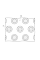
- FIG. 2 is a schematic diagram showing a part of the hollow fiber membrane fabric; It is a schematic sectional drawing explaining an example of the formation method of a baffle. It is a schematic sectional drawing explaining an example of the formation method of a baffle.
- FIG. 3 is a schematic cross-sectional view enlarging a part of FIG. 2; It is the graph which showed
- FIG. 1 is a schematic cross-sectional view of the degassing module according to the embodiment.
- FIG. 2 is a schematic cross-sectional view along line II-II shown in FIG. 3 to 5 are schematic sectional views enlarging a part of the degassing module shown in FIG.
- the degassing module 1 according to the embodiment is a module for degassing the liquid L.
- the liquid L to be degassed by the degassing module 1 is not particularly limited. Examples include organic solvents such as alcohols and hydrocarbons, and ionic liquids.
- the degassing module 1 includes a pipe 2 , a hollow fiber membrane group 3 , a housing 4 , partitions 5 and baffles 6 .
- the pipe 2 is a cylindrical member extending linearly along the central axis A.
- the direction in which the pipe 2 extends cylindrically, that is, the direction of the central axis A is called an extension direction D.
- the pipe 2 forms an intra-pipe flow path 23 having a liquid supply port 21 and a liquid discharge port 22 .
- the pipe internal flow path 23 is a flow path formed by the inner peripheral surface of the pipe 2 and through which the liquid L can flow.
- a plurality of holes 24 are formed in the pipe 2 to open the pipe internal flow path 23 .
- the plurality of holes 24 are holes for discharging the liquid L from the in-pipe channel 23 to the outside of the pipe 2 and for letting the liquid L into the in-pipe channel 23 from the outside of the pipe 2 .
- the pipe 2 has a hole-formed portion 25 , a first hole-unformed portion 26 and a second hole-unformed portion 27 .
- the hole forming portion 25 is a portion in which a plurality of holes 24 are formed.
- the first non-hole-formed portion 26 and the second non-hole-formed portion 27 are portions where the plurality of holes 24 are not formed.
- the hole forming portion 25 is located in the central portion of the pipe 2 in the extending direction D.
- the first non-hole forming portion 26 is adjacent to the liquid supply port 21 side of the hole forming portion 25 in the extending direction D.
- the second hole non-formed portion 27 is adjacent to the hole formed portion 25 in the extension direction D on the liquid outlet 22 side.
- the inner and outer diameters of the hole-formed portion 25, the first hole-unformed portion 26, and the second hole-unformed portion 27 are not particularly limited.
- the inner and outer diameters of the hole-formed portion 25 may be larger than the inner and outer diameters of the first non-hole-formed portion 26 and the second non-hole-formed portion 27.
- the hole-formed portion 25, the first hole-unformed portion 26, and the second hole-unformed portion 27 are separate members, and the small-diameter first hole-unformed portion 26 is provided at both ends of the large-diameter hole-formed portion 25.
- the pipe 2 may be configured by inserting the second non-hole forming portion 27 .
- the hollow fiber membrane group 3 is formed by winding the hollow fiber membrane fabric 8 around the outer peripheral side of the pipe 2 so as to cover the plurality of holes 24 . That is, the hollow fiber membrane group 3 is composed of the hollow fiber membrane fabric 8 arranged on the outer peripheral side of the pipe 2 so as to cover the plurality of holes 24 .
- FIG. 6 is a schematic diagram showing part of the hollow fiber membrane fabric.
- the hollow fiber membrane fabric 8 has a plurality of hollow fiber membranes 31 as wefts and warps 9 .
- the hollow fiber membrane fabric 8 is constructed by weaving a plurality of hollow fiber membranes 31 arranged substantially parallel to each other and warp yarns 9 extending in a direction substantially orthogonal to the plurality of hollow fiber membranes 31 .
- the weaving structure of the plurality of hollow fiber membranes 31 and the warp yarns 9 is not particularly limited, and various weaving structures can be adopted.
- the hollow fiber membrane fabric 8 is wound around the pipe 2 so that the plurality of hollow fiber membranes 31 extend in the extension direction D like the pipe 2 .
- Each of the plurality of hollow fiber membranes 31 is a hollow fiber membrane that allows the gas G to permeate but the liquid L not to permeate.
- the material, membrane shape, membrane form, and the like of each of the plurality of hollow fiber membranes 31 are not particularly limited.
- Examples of the material for each of the plurality of hollow fiber membranes 31 include polyolefin resins such as polypropylene, polyethylene, and polymethylpentene; silicone resins such as polydimethylsiloxane copolymers thereof; fluorine resins such as PTFE and vinylidene fluoride. resin.
- each of the plurality of hollow fiber membranes 31 examples include a porous film, a microporous film, and a homogeneous film having no porosity (non-porous film).
- Examples of the form of each of the plurality of hollow fiber membranes 31 include a symmetrical membrane (homogeneous membrane) in which the chemical or physical structure of the entire membrane is homogeneous, and an asymmetric membrane in which the chemical or physical structure of the membrane differs depending on the part of the membrane.
- membranes heterogeneous membranes
- Asymmetric membranes are membranes having non-porous dense layers and porous layers.
- the dense layer may be formed anywhere in the film, such as the surface layer of the film or the inside of the porous film.
- Heterogeneous films also include composite films with different chemical structures and multi-layer structures such as three-layer structures.
- a heterogeneous film using poly-4-methylpentene-1 resin is particularly preferable because it has a dense layer that blocks the liquid L.
- a dense layer is formed on the outer surface.
- the hollow fiber membrane group 3 is arranged on the outer peripheral side of the hole formed portion 25 of the pipe 2, and the first hole non-formed portion 26 and the second hole non-formed portion of the pipe 2 27 is not arranged on the outer peripheral side. That is, the hollow fiber membrane group 3 is configured by winding the hollow fiber membrane fabric around the hole forming portion 25 . Therefore, the hollow fiber membrane group 3 is formed in a substantially cylindrical shape.
- an inter-membrane space S1 through which the liquid L can flow is formed between the plurality of hollow fiber membranes 31 (between the adjacent hollow fiber membranes 31).
- the inter-membrane space S1 is also formed between the plurality of hollow fiber membranes 31 in the circumferential direction of the pipe 2 and is also formed between the plurality of hollow fiber membranes 31 in the circumferential direction of the pipe 2 .
- the inter-membrane space S1 is also formed between the adjacent hollow fiber membranes 31 in the hollow fiber membrane fabric 8, and the hollow fiber membranes 31 in the hollow fiber membrane fabric 8 on the inner peripheral side (inner hollow fiber membranes 31) It is also formed between the membrane 31) and the hollow fiber membrane 31 (hollow fiber membrane 31 on the outer peripheral side) in the hollow fiber membrane fabric 8 on the outer peripheral side.
- the housing 4 is connected to the outer peripheral surface of the pipe 2 and accommodates the hollow fiber membrane group 3 .
- the housing 4 is formed in a cylindrical shape extending in the extending direction D of the pipe 2 . Both ends of the housing 4 in the extending direction D are airtightly connected to the outer peripheral surface of the pipe 2 .
- the connection of the housing 4 to the pipe 2 can be performed, for example, by welding, adhesion, or the like. Both ends of the pipe 2 do not need to protrude from the housing 4 , but in the present embodiment, the ends of the pipe 2 protrude from the housing 4 in order to facilitate connection of other members to the pipe 2 .
- An intake port 41 is formed in the housing 4 .
- the intake port 41 is an opening for sucking air from the housing 4 .
- the intake port 41 is composed of a first intake port 42 and a second intake port 43 .
- Each of the first intake port 42 and the second intake port 43 is an opening for sucking air from the housing 4 .
- a suction device (not shown) such as a vacuum pump is connected to the first intake port 42 and the second intake port 43, for example.
- a liquid circulation space S2 is formed in the housing 4 .
- the liquid flow space S2 is a space between the hollow fiber membrane group 3 and the housing 4 through which the liquid L can flow.
- the liquid circulation space S2 is a space formed between the hollow fiber membrane group 3 and the housing 4 at least when the degassing module 1 is not in use. Therefore, the hollow fiber membrane group 3 is not in contact with the inner peripheral surface of the housing 4 when the degassing module 1 is not in use. After the degassing module 1 is used, the hollow fiber membrane group 3 may come into contact with the inner peripheral surface of the housing 4 due to swelling of the plurality of hollow fiber membranes 31 .
- the partition part 5 partitions the area inside the housing 4 into an internal area R1 and an external area R2.
- the internal region R ⁇ b>1 is a region including the inner peripheral side spaces 32 of the plurality of hollow fiber membranes 31 .
- the outer region R2 is a region containing the inter-membrane space S1. Therefore, each of the plurality of hollow fiber membranes 31 serves as a boundary between the inner region R1 and the outer region R2.
- Each of the plurality of hollow fiber membranes 31 prevents passage of the liquid L from the outer region R2 to the inner region R1, and prevents gas G (dissolved gas in the liquid L, gas in the liquid L) from the outer region R2 to the inner region R1 air bubbles, etc.) to pass through.
- the partition section 5 has a first sealing section 51 and a second sealing section 52 .
- the first sealing portion 51 is arranged at the first end portion 33 on one side of the hollow fiber membrane group 3 in the extending direction D. As shown in FIG.
- the first end portion 33 is the end portion on the liquid supply port 21 side in the extending direction D.
- the first end portion 33 of the hollow fiber membrane group 3 is fixed to the outer peripheral surface of the pipe 2 and the inner peripheral surface of the housing 4 by the first sealing portion 51 .
- the second sealing portion 52 is arranged at the second end portion 34 on the other side of the hollow fiber membrane group 3 in the extending direction D. As shown in FIG.
- the second end portion 34 is the end portion on the side of the liquid outlet 22 in the extending direction D. As shown in FIG.
- the second end portion 34 of the hollow fiber membrane group 3 is fixed to the outer peripheral surface of the pipe 2 and the inner peripheral surface of the housing 4 by the second sealing portion 52 .
- the first sealing portion 51 and the second sealing portion 52 are made of resin, for example.
- resins used for the first sealing portion 51 and the second sealing portion 52 include epoxy resins, urethane resins, ultraviolet curing resins, and polyolefin resins such as polyethylene and polypropylene.
- Each of the first sealing portion 51 and the second sealing portion 52 fills the entire area between the pipe 2 and the housing 4 except for the plurality of hollow fiber membranes 31 in the orthogonal cross section orthogonal to the extending direction D. ing. That is, each of the first sealing portion 51 and the second sealing portion 52 is located between the pipe 2 and the hollow fiber membrane group 3, between the plurality of hollow fiber membranes 31, and between the hollow fiber membrane group 3 and the housing 4. is filled between The inner peripheral space 32 of each of the plurality of hollow fiber membranes 31 is open from the first sealing portion 51 to the liquid supply port 21 side, and is open from the second sealing portion 52 to the liquid discharge port 22 side. is open.
- the first sealing portion 51 is arranged between the hole forming portion 25 and the first hole non-forming portion 26 in the extending direction D.
- the second sealing portion 52 is arranged between the hole forming portion 25 and the second hole non-forming portion 27 in the extending direction D.
- the plurality of holes 24 of the pipe 2 are formed between the first sealing portion 51 and the second sealing portion 52 in the extending direction D.
- the area between the pipe 2 and the housing 4 on the side of the liquid supply port 21 of the first sealing portion 51 is an internal area R1.
- a region between the pipe 2 and the housing 4 on the liquid outlet 22 side of the second sealing portion 52 is an internal region R1.
- the first intake port 42 is arranged on the side opposite to the second sealing portion 52 of the first sealing portion 51 in the extending direction D, that is, on the liquid supply port 21 side of the first sealing portion 51 in the extending direction D. It is The first intake port 42 communicates with an internal region R ⁇ b>1 located between the pipe 2 and the housing 4 on the liquid supply port 21 side of the first sealing portion 51 .
- the second intake port 43 is arranged on the side of the second sealing portion 52 opposite to the first sealing portion 51 in the extending direction D, that is, on the liquid outlet 22 side of the second sealing portion 52 in the extending direction D. It is The second intake port 43 communicates with an internal region R1 located between the pipe 2 and the housing 4 on the side of the liquid discharge port 22 of the second sealing portion 52 .
- the baffle 6 separates the first sealing portion 51 and the second sealing portion 52 in the extending direction D in order to detour the liquid L supplied to the liquid supply port 21 and bring it into contact with the plurality of hollow fiber membranes 31 . placed in between.
- the region of the degassing module 1 between the first sealing portion 51 and the baffle 6 in the extending direction D is called an upstream portion 10
- the region between the baffle 6 and the second sealing portion 52 in the extending direction D is called an upstream portion 10.
- the region of the degassing module 1 in between is called the downstream portion 11 .
- the baffle 6 partitions the pipe inner channel 23 and the inter-membrane space S1 in the extending direction D. More specifically, the baffle 6 partitions the in-pipe flow path 23 in the extending direction D and partitions the external region R2 in the extending direction D such that a baffle clearance C is formed between the baffle 6 and the housing 4 . That is, the pipe internal flow path 23 is partitioned in the extending direction D by the baffle 6 .
- the inter-membrane space S1 is partitioned in the extending direction D by the baffle 6 .
- the external region R2 is partitioned in the extending direction D by the baffle 6 so that a baffle clearance C is formed between the baffle 6 and the housing 4 .
- the liquid L supplied from the liquid supply port 21 to the pipe internal flow path 23 exits the pipe 2 in the upstream section 10, passes through the inter-membrane space S1, and passes through the baffle clearance C between the baffle 6 and the housing 4. and enters the pipe 2 at the downstream portion 11 through the intermembrane space S1.
- the position of the baffle 6 in the extending direction D can be any position between the first sealing portion 51 and the second sealing portion 52 .
- the baffle 6 divides the space between the first sealing portion 51 and the second sealing portion 52 into three in the extending direction D. can be placed in the center of the
- the baffle 6 has an inner baffle 61 and an outer baffle 62.
- the inner baffle 61 is arranged on the inner peripheral side of the pipe 2 and partitions the pipe inner flow path 23 in the extending direction D.
- the outer baffle 62 is arranged on the outer peripheral side of the pipe 2 and partitions at least part of the inter-membrane space S1 in the extending direction D.
- the inner baffle 61 may completely partition the pipe inner channel 23 in the extending direction D, or may imperfectly partition the pipe inner channel 23 in the extending direction D. That is, even if the inner baffle 61 completely blocks the pipe channel 23 so that the liquid L cannot pass from the pipe channel 23 of the upstream portion 10 to the pipe channel 23 of the downstream portion 11, good. In addition, the inner baffle 61 partially blocks the pipe internal flow path 23 so that the liquid L can pass from the pipe internal flow path 23 of the upstream section 10 to the pipe internal flow path 23 of the downstream section 11. good. Even if the inner baffle 61 partially closes the pipe channel 23 , the inner baffle 61 prevents the passage of the liquid L from the pipe channel 23 in the upstream portion 10 to the pipe channel 23 in the downstream portion 11 . Since it is partially blocked, the liquid L supplied to the liquid supply port 21 can be detoured and brought into contact with the plurality of hollow fiber membranes 31 .
- the inner baffle 61 is made of resin, for example.
- the resin used for the inner baffle 61 include urethane-based resins such as polyurethane (PU) and thermoplastic polyurethane (TPU); polycarbonate (PC); polyvinyl chloride (PVC); Vinyl chloride resin; acrylic resin such as polyacrylic acid, polymethacrylic acid, polymethyl acrylate, polymethyl methacrylate (PMMA), polyethyl methacrylate; polyethylene terephthalate (PET), polybutylene terephthalate Polytrimethylene terephthalate, polyethylene naphthalate, polyester resins such as polybutylene naphthalate; polyamide resins such as nylon (registered trademark); polystyrene (PS), imide-modified polystyrene, acrylonitrile Polystyrene resins such as butadiene-styrene (ABS) resin, imide-modified ABS resin, styrene-acrylonit
- the outer baffle 62 is arranged in the inter-membrane space S1 (between the plurality of hollow fiber membranes 31) to partition the inter-membrane space S1 in the extending direction D.
- the outer baffle 62 may completely partition the inter-membrane space S1 in the extending direction D, or may imperfectly partition the inter-membrane space S1 in the extending direction D. That is, the outer baffle 62 may completely block the inter-membrane space S1 so that the liquid L cannot pass from the inter-membrane space S1 of the upstream portion 10 to the inter-membrane space S1 of the downstream portion 11 .
- the outer baffle 62 may partially block the inter-membrane space S1 so as to allow passage of the liquid L from the inter-membrane space S1 of the upstream portion 10 to the inter-membrane space S1 of the downstream portion 11 . Even if the outer baffle 62 partially blocks the inter-membrane space S1, passage of the liquid L from the inter-membrane space S1 of the upstream portion 10 to the inter-membrane space S1 of the downstream portion 11 is partially blocked by the outer baffle 62. Therefore, the liquid L supplied to the liquid supply port 21 can be bypassed and brought into contact with the plurality of hollow fiber membranes 31 .
- the outer baffle 62 may also be arranged in the pipe-side space S3, which is the space between the pipe 2 and the hollow fiber membrane group 3, and partition the pipe-side space S3 in the extending direction D.
- the outer baffle 62 may completely partition the pipe-side space S3 in the extending direction D, or may imperfectly partition the pipe-side space S3 in the extending direction D. That is, the outer baffle 62 may completely block the pipe-side space S3 so that the liquid L cannot pass from the pipe-side space S3 of the upstream portion 10 to the pipe-side space S3 of the downstream portion 11 .
- the outer baffle 62 may partially block the pipe-side space S3 so that the liquid L can pass from the pipe-side space S3 of the upstream portion 10 to the pipe-side space S3 of the downstream portion 11 . Note that if a portion of the liquid L supplied to the liquid supply port 21 can be detoured and brought into contact with the plurality of hollow fiber membranes 31, the outer baffle 62 will not be arranged in the pipe-side space S3 but will be located in the pipe-side space S3. may not be partitioned in the extending direction D.
- the outer baffle 62 is separated from the housing 4. However, the outer baffle 62 may be in contact with the housing 4 as long as the baffle clearance C is formed even partially between the outer baffle 62 and the housing 4 . Although the outer baffle 62 is not arranged in the liquid circulation space S2, it is arranged in the liquid circulation space S2 if the baffle clearance C is formed even partially between the outer baffle 62 and the housing 4. may
- the outer baffle 62 is made of resin, for example.
- the resin used for the outer baffle 62 include urethane-based resins such as polyurethane (PU) and thermoplastic polyurethane (TPU); polycarbonate (PC); polyvinyl chloride (PVC); Vinyl chloride resin; acrylic resin such as polyacrylic acid, polymethacrylic acid, polymethyl acrylate, polymethyl methacrylate (PMMA), polyethyl methacrylate; polyethylene terephthalate (PET), polybutylene terephthalate Polytrimethylene terephthalate, polyethylene naphthalate, polyester resins such as polybutylene naphthalate; polyamide resins such as nylon (registered trademark); polystyrene (PS), imide-modified polystyrene, acrylonitrile Polystyrene resins such as butadiene-styrene (ABS) resin, imide-modified ABS resin, styrene-acrylonit
- FIG. 7 and 8 are schematic cross-sectional views explaining an example of a method of forming the baffle 6.
- FIG. 6 When forming the baffle 6, first, as shown in FIG. This disk-shaped member becomes the inner baffle 61 .
- the hollow fiber membrane fabric 8 is wound around the pipe 2 so as to cover the plurality of holes 24 of the pipe 2 .
- the molten resin 13 is applied to the position corresponding to the outer baffle 62 of the fabric inner surface 8a.
- the hollow fiber membrane fabric 8 coated with the molten resin 13 is wound around the pipe 2 .
- the hollow fiber membrane fabric 8 on the inner layer side and the hollow fiber membrane fabric 8 on the outer layer side are impregnated with the molten resin 13 so that the positions corresponding to the outer baffles 62 are filled.
- the molten resin 13 becomes the outer baffle 62 by curing the molten resin 13 .
- the internal region R1 is sucked from the first intake port 42 and the second intake port 43, and the liquid L is supplied from the liquid supply port 21 to the pipe internal channel 23.
- Intake of the internal region R1 from the first intake port 42 and the second intake port 43 is performed by connecting a suction device (not shown) such as a vacuum pump to the first intake port 42 and the second intake port 43, for example. It can be done by activating the device.
- a suction device such as a vacuum pump
- the liquid supplied to the pipe internal flow path 23 passes through the plurality of holes 24 formed in the pipe 2 in the upstream section 10 so as to bypass the baffle 6, exits the pipe 2, and enters the inter-membrane space S1. pass through
- gas G such as dissolved gas in the liquid L and air bubbles contained in the liquid L is released into the plurality of hollow fiber membranes. 31, whereby the liquid L is degassed.
- the liquid L passes through the baffle clearance C, passes through the inter-membrane space S1 in the downstream portion 11 and enters the pipe 2 through a plurality of holes 24 formed in the pipe 2 .
- each of the plurality of hollow fiber membranes 31 since the inner peripheral space 32 of each of the plurality of hollow fiber membranes 31 is in a decompressed state, the dissolved gas in the liquid L and the gas G such as air bubbles contained in the liquid L are released into the plurality of hollow fibers. Each of the membranes 31 is passed through, whereby the liquid L is degassed. After that, the deaerated liquid L entering the pipe 2 is discharged from the liquid discharge port 22 .
- the internal region R1 is sucked from the first intake port 42 and the second intake port 43, and the liquid L is supplied from the liquid supply port 21 to the pipe channel 23.
- the liquid L can be degassed.
- the pipe internal flow path 23 and the inter-membrane space S1 are partitioned in the extending direction D by the baffle 6 . Therefore, when the liquid L is supplied from the liquid supply port 21 to the pipe internal channel 23, the liquid L exits the pipe 2 on the liquid supply port 21 side of the baffle 6, passes through the inter-membrane space S1, and flows through the baffle 6 and the housing.
- the warp yarns 9 of the hollow fiber membrane fabric 8 do not contribute to the degassing of the liquid L, and on the contrary, hinder the flow of the liquid.
- the diameter of the warp was made extremely smaller than the diameter of each of the plurality of hollow fiber membranes.
- the pressure loss of the liquid L was found to be able to reduce
- FIG. 9 is a schematic sectional view enlarging a part of FIG.
- FIG.2 and FIG.9 has shown the orthogonal cross section orthogonal to the extension direction D.
- FIG. As shown in FIGS. 2 and 9, the area between the housing 4 and the pipe 2 in the orthogonal cross section perpendicular to the extension direction D is called a housing area R3.
- the housing region R3 is a region containing a plurality of hollow fiber membranes 31.
- a spatial region R4 a region excluding the plurality of hollow fiber membranes 31 between the housing 4 and the pipe 2 in an orthogonal cross section perpendicular to the extending direction D.
- the spatial region R4 is a region obtained by excluding the hatched region in FIG. 9 from the accommodation region R3.
- the ratio of the area of the space region R4 to the area of the accommodation region R3 (the ratio of the area of the space region R4/the area of the accommodation region R3) is called the porosity.
- the ratio of the warp diameter D2 to the diameter D1 of each of the plurality of hollow fiber membranes is 0.6 or more. That is, D2/D1 is 0.6 or more. In addition, when this ratio of 0.6 is expressed as a percentage, it becomes 60%. In this case, the ratio of diameter D2 to diameter D1 may be 0.7 or more, or 0.8 or more.
- the ratio of the diameter D2 to the diameter D1 is 0.6 or more, preferably 0.7 or more, and more preferably 0.8 or more in this way, the flow of the liquid L that crosses the baffle 6 and enters the pipe 2 again Therefore, the degree of reduction of the inter-membrane space S1 between the plurality of hollow fiber membranes 31 when the plurality of hollow fiber membranes 31 are pressed toward the pipe 2 can be reduced. Thereby, the pressure loss of the liquid L can be reduced.
- the ratio of diameter D2 to diameter D1 may be 1.5 or less, 1 or less, or 0.8 or less. In addition, when this ratio of 1.5 is expressed as a percentage, it becomes 150%.
- the ratio of the diameter D2 to the diameter D1 preferably 1 or less, more preferably 0.8 or less, the number of the plurality of hollow fiber membranes 31 accommodated in the housing 4 and the plurality of It is possible to prevent the membrane area of the hollow fiber membrane 31 from becoming too small.
- the diameter D2 of the warp yarns 9 may be 50 ⁇ m or more, 100 ⁇ m or more, or 150 ⁇ m or more.
- the diameter D2 of the warp yarns 9 may be 50 ⁇ m or more, preferably 100 ⁇ m or more, and more preferably 150 ⁇ m or more.
- the diameter D2 of the warp yarns 9 may be 300 ⁇ m or less, 250 ⁇ m or less, or 200 ⁇ m or less.
- the diameter D2 of the warp yarns 9 may be 300 ⁇ m or less, preferably 250 ⁇ m or less, more preferably 200 ⁇ m or less, the number of the plurality of hollow fiber membranes 31 accommodated in the housing 4 and the number of the plurality of hollow fiber membranes 31 It is possible to prevent the area from becoming too small.
- the diameter D1 of each of the plurality of hollow fiber membranes 31 may be 50 ⁇ m or more and 500 ⁇ m or less, 100 ⁇ m or more and 350 ⁇ m or less, or 150 ⁇ m or more and 250 ⁇ m or less.
- the diameter D1 of each of the plurality of hollow fiber membranes 31 may be 50 ⁇ m or more and 500 ⁇ m or less, 100 ⁇ m or more and 350 ⁇ m or less, or 150 ⁇ m or more and 250 ⁇ m or less.
- the ratio of the pitch P of the warp yarns 9 to the diameter D1 of each of the hollow fiber membranes 31 may be 600 or less, 100 or less, or 40 or less. That is, P/D1 may be 600 or less, 100 or less, or 40 or less. In addition, when this ratio of 600 is expressed as a percentage, it becomes 60000%. In this way, by setting the ratio of the pitch P to the diameter D1 to 600 or less, preferably 100 or less, more preferably 40 or less, the flow of the liquid L that crosses the baffle 6 and enters the pipe 2 again causes a plurality of hollow fiber membranes to be formed. The degree of deformation of each of the plurality of hollow fiber membranes when the hollow fiber membranes 31 are pressed toward the pipe 2 can be reduced. Thereby, the pressure loss of the liquid L can be further reduced.
- the ratio of the pitch P of the warp yarns 9 to the diameter D1 of each of the hollow fiber membranes 31 may be 2 or more, 5.7 or more, or 16 or more. That is, P/D1 may be 2 or more, 5.7 or more, or 16 or more. The ratio of 2 is 200% when expressed as a percentage.
- the ratio of the pitch P to the diameter D1 to 2 or more, preferably 5.7 or more, and more preferably 16 or more, the pressure loss of the liquid L caused by passing through the warp yarns 9 can be reduced. .
- the pitch P of the warp yarns 9 may be 30 mm or less, 10 mm or less, or 6 mm or less.
- the plurality of hollow fiber membranes 31 are separated into the pipe 2 by the flow of the liquid L that crosses the baffle 6 and enters the pipe 2 again.
- the degree of deformation of each of the plurality of hollow fiber membranes 31 when pressed to the side can be reduced. Thereby, the pressure loss of the liquid L can be appropriately reduced.
- the pitch P of the warp yarns 9 may be 1 mm or more, 2 mm or more, or 4 mm or more.
- the pitch P may be 1 mm or more, preferably 2 mm or more, and more preferably 4 mm or more.
- the porosity which is the ratio of the area of the space region R4 to the area of the accommodation region R3, may be 30% or more and 80% or less, may be 45% or more and 75% or less, or may be 60% or more and 70% or less. There may be. That is, (area of space region R4)/(area of accommodation region R3) ⁇ 100 may be 30% or more and 80% or less, 45% or more and 75% or less, or 60% or more and 70% or less.
- the pressure loss of the liquid L can be reduced while the housing 4
- the number of the plurality of hollow fiber membranes 31 to be accommodated and the membrane area of the plurality of hollow fiber membranes 31 can be sufficiently secured.
- the baffle 6 has an inner baffle 61 arranged on the inner peripheral side of the pipe 2 and an outer baffle 62 arranged on the outer peripheral side of the pipe 2, so that the pipe 2 extends in the extending direction D.
- the baffle 6 can be arranged without dividing into two.
- each of the first sealing portion 51 and the second sealing portion 52 has a plurality of hollow fiber membranes between the pipe 2 and the housing 4 in an orthogonal cross section orthogonal to the extending direction D.
- the entire area except 31 is filled, and a plurality of holes 24 of the pipe 2 are formed between the first sealing portion 51 and the second sealing portion 52 . Therefore, the first sealing portion 51 and the second sealing portion 52 can partition the area inside the housing 4 into the internal area R1 and the external area R2.
- the extending direction D The liquid L can be brought into contact with the plurality of hollow fiber membranes 31 over a long range.
- the first inlet 42 and the second inlet 43 are formed outside the first sealing section 51 and the second sealing section 52 in the extending direction D. Air can be sucked into the inner peripheral side spaces 32 of the plurality of hollow fiber membranes 31 from both ends of the hollow fiber membranes 31 . Thereby, the degassing efficiency of the liquid L can be improved.
- the pressure loss of the liquid L can be reduced.
- one aspect of the present invention is not limited to the above embodiment.
- the pipe and the housing are separate members, but the pipe and the housing may be integrated as long as there is no manufacturing problem.
- Comparative example 1 As Comparative Example 1, a degassing module having the same configuration as that of the above-described embodiment except that the ratio of the diameter of the warp to the diameter of each of the plurality of hollow fiber membranes was set to 0.29 was produced.
- the diameter of each of the plurality of hollow fiber membranes was set to 210 ⁇ m, and the diameter of the warp was set to 60 ⁇ m (22 dtx). was set to 0.29.
- the warp pitch was set to 8.4 mm, so that the ratio of the warp pitch to the diameter of each of the plurality of hollow fiber membranes was set to 40 (40 times).
- Example 1 As Example 1, a degassing module having the same configuration as in Comparative Example 1 was produced, except that the ratio of the diameter of the warp to the diameter of each of the plurality of hollow fiber membranes was set to 0.71.
- the diameter of each of the plurality of hollow fiber membranes was 210 ⁇ m, and the diameter of the warp was 150 ⁇ m (56 dtx). was set to 0.71.
- the warp pitch was set to 8.4 mm, so that the ratio of the warp pitch to the diameter of each of the plurality of hollow fiber membranes was set to 40 (40 times).
- Example 2 As Example 2, a degassing module having the same configuration as in Example 1 was produced, except that the ratio of the warp pitch to the diameter of each of the plurality of hollow fiber membranes was set to 19 (19 times).
- the diameter of each of the plurality of hollow fiber membranes is 210 ⁇ m
- the diameter of the warp is 150 ⁇ m (56 dtx). was set to 0.71.
- the warp pitch was set to 4.2 mm, so that the ratio of the warp pitch to the diameter of each of the plurality of hollow fiber membranes was 19 (19 times).
- Example 1 As Experiment 1, each degassing module of Comparative Example 1, Example 1, and Example 2 was used to measure the pressure loss of the liquid. In Experiment 1, the flow rate of the liquid supplied to the degassing module was changed, and the pressure loss of the liquid from the liquid supply port to the liquid discharge port of the degassing module was measured. FIG. 10 shows the measurement results. FIG. 10 is a graph showing the measurement results of pressure loss.
- the liquid pressure loss is higher in the degassing module in which the ratio of the warp diameter to the diameter of each hollow fiber membrane is 0.71.
- the degassing module of Comparative Example 1 in which the ratio of the warp diameter to the warp diameter is 0.29, it is much smaller.
- the pressure loss of the liquid in the degassing module of Example 1 is greater than the pressure loss of the liquid in the degassing module of Comparative Example 1. decreased by 37%.
- the pressure loss of the liquid in the degassing module of Example 2 in which the ratio of the warp pitch to the diameter of each of the hollow fiber membranes is 19, is higher than that of the warp to the diameter of each of the hollow fiber membranes.
- the pressure loss of the liquid in the degassing module of Example 2 is decreased by 53%.
- One aspect of the present invention is applicable to a degassing module for degassing a liquid and a liquid degassing method.
Landscapes
- Chemical & Material Sciences (AREA)
- Chemical Kinetics & Catalysis (AREA)
- Engineering & Computer Science (AREA)
- Water Supply & Treatment (AREA)
- Manufacturing & Machinery (AREA)
- Separation Using Semi-Permeable Membranes (AREA)
- Degasification And Air Bubble Elimination (AREA)
Priority Applications (5)
| Application Number | Priority Date | Filing Date | Title |
|---|---|---|---|
| US18/719,877 US20250050242A1 (en) | 2021-12-28 | 2022-12-23 | Degassing module and method for degassing liquid |
| KR1020247011346A KR20240051288A (ko) | 2021-12-28 | 2022-12-23 | 탈기 모듈 및 액체의 탈기 방법 |
| CN202280082099.7A CN118382491A (zh) | 2021-12-28 | 2022-12-23 | 脱气组件及液体的脱气方法 |
| EP22915966.0A EP4458444A4 (en) | 2021-12-28 | 2022-12-23 | DEGASING MODULE, AND LIQUID DEGASING PROCESS |
| JP2023570975A JP7683745B2 (ja) | 2021-12-28 | 2022-12-23 | 脱気モジュール及び液体の脱気方法 |
Applications Claiming Priority (2)
| Application Number | Priority Date | Filing Date | Title |
|---|---|---|---|
| JP2021-213996 | 2021-12-28 | ||
| JP2021213996 | 2021-12-28 |
Publications (1)
| Publication Number | Publication Date |
|---|---|
| WO2023127743A1 true WO2023127743A1 (ja) | 2023-07-06 |
Family
ID=86999128
Family Applications (1)
| Application Number | Title | Priority Date | Filing Date |
|---|---|---|---|
| PCT/JP2022/047699 Ceased WO2023127743A1 (ja) | 2021-12-28 | 2022-12-23 | 脱気モジュール及び液体の脱気方法 |
Country Status (6)
| Country | Link |
|---|---|
| US (1) | US20250050242A1 (https=) |
| EP (1) | EP4458444A4 (https=) |
| JP (1) | JP7683745B2 (https=) |
| KR (1) | KR20240051288A (https=) |
| CN (1) | CN118382491A (https=) |
| WO (1) | WO2023127743A1 (https=) |
Cited By (2)
| Publication number | Priority date | Publication date | Assignee | Title |
|---|---|---|---|---|
| JP7827236B1 (ja) * | 2024-09-05 | 2026-03-10 | Dic株式会社 | 中空糸膜エレメント、中空糸膜モジュール、脱気方法、及びガス付加方法 |
| WO2026053703A1 (ja) * | 2024-09-05 | 2026-03-12 | Dic株式会社 | 中空糸膜エレメント、中空糸膜モジュール、脱気方法、及びガス付加方法 |
Families Citing this family (2)
| Publication number | Priority date | Publication date | Assignee | Title |
|---|---|---|---|---|
| KR20250152849A (ko) | 2024-04-17 | 2025-10-24 | 주식회사 엘지에너지솔루션 | 다이 코터 |
| CN119139888B (zh) * | 2024-11-19 | 2025-03-11 | 厦门海洋职业技术学院 | 一种旋转气体膜分离设备及其废水脱氨系统 |
Citations (7)
| Publication number | Priority date | Publication date | Assignee | Title |
|---|---|---|---|---|
| JPS63236502A (ja) * | 1987-03-10 | 1988-10-03 | アクゾ・エヌ・ヴエー | 多層中空繊維巻体、その製法、熱伝達法、物質交換法、物質転送法、物質分離法、透析法及び酸素付加法 |
| JPH02107317A (ja) * | 1988-10-14 | 1990-04-19 | Dainippon Ink & Chem Inc | 多孔質中空糸膜型気液接触装置 |
| JPH05245347A (ja) * | 1991-12-31 | 1993-09-24 | Hoechst Celanese Corp | 流れ差向けバッフルを持つ螺旋状に巻付けた中空糸膜織物カートリッジ及びモジュール |
| JP2000084369A (ja) * | 1998-09-10 | 2000-03-28 | Dainippon Ink & Chem Inc | 中空糸膜型気液ガス交換装置及びそのガス交換方法 |
| JP2003038904A (ja) | 2001-06-21 | 2003-02-12 | Celgard Inc | 中空繊維膜の接触器 |
| JP2013502315A (ja) * | 2009-08-17 | 2013-01-24 | セルガード エルエルシー | 高圧液体脱気膜コンタクタならびに製造法および使用法 |
| JP2014172019A (ja) * | 2013-03-12 | 2014-09-22 | Mitsubishi Rayon Co Ltd | 中空糸膜シート状物およびこれを用いた中空糸膜モジュールの製造方法 |
Family Cites Families (1)
| Publication number | Priority date | Publication date | Assignee | Title |
|---|---|---|---|---|
| JPH0696098B2 (ja) * | 1988-05-27 | 1994-11-30 | 株式会社クラレ | 中空糸型流体処理装置 |
-
2022
- 2022-12-23 EP EP22915966.0A patent/EP4458444A4/en active Pending
- 2022-12-23 CN CN202280082099.7A patent/CN118382491A/zh active Pending
- 2022-12-23 KR KR1020247011346A patent/KR20240051288A/ko active Pending
- 2022-12-23 JP JP2023570975A patent/JP7683745B2/ja active Active
- 2022-12-23 US US18/719,877 patent/US20250050242A1/en active Pending
- 2022-12-23 WO PCT/JP2022/047699 patent/WO2023127743A1/ja not_active Ceased
Patent Citations (7)
| Publication number | Priority date | Publication date | Assignee | Title |
|---|---|---|---|---|
| JPS63236502A (ja) * | 1987-03-10 | 1988-10-03 | アクゾ・エヌ・ヴエー | 多層中空繊維巻体、その製法、熱伝達法、物質交換法、物質転送法、物質分離法、透析法及び酸素付加法 |
| JPH02107317A (ja) * | 1988-10-14 | 1990-04-19 | Dainippon Ink & Chem Inc | 多孔質中空糸膜型気液接触装置 |
| JPH05245347A (ja) * | 1991-12-31 | 1993-09-24 | Hoechst Celanese Corp | 流れ差向けバッフルを持つ螺旋状に巻付けた中空糸膜織物カートリッジ及びモジュール |
| JP2000084369A (ja) * | 1998-09-10 | 2000-03-28 | Dainippon Ink & Chem Inc | 中空糸膜型気液ガス交換装置及びそのガス交換方法 |
| JP2003038904A (ja) | 2001-06-21 | 2003-02-12 | Celgard Inc | 中空繊維膜の接触器 |
| JP2013502315A (ja) * | 2009-08-17 | 2013-01-24 | セルガード エルエルシー | 高圧液体脱気膜コンタクタならびに製造法および使用法 |
| JP2014172019A (ja) * | 2013-03-12 | 2014-09-22 | Mitsubishi Rayon Co Ltd | 中空糸膜シート状物およびこれを用いた中空糸膜モジュールの製造方法 |
Cited By (2)
| Publication number | Priority date | Publication date | Assignee | Title |
|---|---|---|---|---|
| JP7827236B1 (ja) * | 2024-09-05 | 2026-03-10 | Dic株式会社 | 中空糸膜エレメント、中空糸膜モジュール、脱気方法、及びガス付加方法 |
| WO2026053703A1 (ja) * | 2024-09-05 | 2026-03-12 | Dic株式会社 | 中空糸膜エレメント、中空糸膜モジュール、脱気方法、及びガス付加方法 |
Also Published As
| Publication number | Publication date |
|---|---|
| KR20240051288A (ko) | 2024-04-19 |
| JPWO2023127743A1 (https=) | 2023-07-06 |
| EP4458444A4 (en) | 2025-12-03 |
| EP4458444A1 (en) | 2024-11-06 |
| JP7683745B2 (ja) | 2025-05-27 |
| TW202330078A (zh) | 2023-08-01 |
| US20250050242A1 (en) | 2025-02-13 |
| CN118382491A (zh) | 2024-07-23 |
Similar Documents
| Publication | Publication Date | Title |
|---|---|---|
| WO2023127743A1 (ja) | 脱気モジュール及び液体の脱気方法 | |
| JP6462131B2 (ja) | 中空糸膜モジュール | |
| KR0161292B1 (ko) | 와권형 가스투과막모듀울과 그것을 사용하는 장치 및 방법 | |
| EP3639912B1 (en) | External circulation-type hollow fiber membrane module | |
| WO2023127506A1 (ja) | 脱気モジュール及び液体の脱気方法 | |
| US8449706B2 (en) | Process for manufacturing deaerating hollow fiber module | |
| JPWO2020138096A1 (ja) | 脱気システム、液体の脱気方法、脱気ユニット、脱気モジュール、脱気システムの製造方法、及び天然資源の産生方法 | |
| US11534536B2 (en) | Heat exchanger and oxygenator | |
| JPH08942A (ja) | 脱湿用中空糸膜モジュール | |
| TWI915611B (zh) | 脫氣模組及液體的脫氣方法 | |
| JP7790637B2 (ja) | 脱気モジュール及び液体の脱気方法 | |
| JP7290208B2 (ja) | 中空糸膜モジュール | |
| JP7827237B1 (ja) | 液体の脱気方法及び脱気モジュール | |
| TW202545614A (zh) | 脫氣模組及液體之脫氣方法 | |
| JP7782762B2 (ja) | 脱気エレメント、脱気モジュール、及び液体の脱気方法 | |
| JP7827235B1 (ja) | 脱気モジュール及び液体の脱気方法 | |
| JP2000042377A (ja) | 平膜状気液接触膜エレメント、平膜状気液接触膜モジュールおよびスパイラル型膜モジュール | |
| HK1153422B (en) | Process for manufacturing deaerating hollow fiber module |
Legal Events
| Date | Code | Title | Description |
|---|---|---|---|
| 121 | Ep: the epo has been informed by wipo that ep was designated in this application |
Ref document number: 22915966 Country of ref document: EP Kind code of ref document: A1 |
|
| WWE | Wipo information: entry into national phase |
Ref document number: 2023570975 Country of ref document: JP |
|
| ENP | Entry into the national phase |
Ref document number: 20247011346 Country of ref document: KR Kind code of ref document: A |
|
| WWE | Wipo information: entry into national phase |
Ref document number: 202280082099.7 Country of ref document: CN |
|
| WWE | Wipo information: entry into national phase |
Ref document number: 18719877 Country of ref document: US |
|
| NENP | Non-entry into the national phase |
Ref country code: DE |
|
| ENP | Entry into the national phase |
Ref document number: 2022915966 Country of ref document: EP Effective date: 20240729 |