WO2023127697A1 - 車載通信装置、通信管理サーバ、プログラム、通信管理システム及び通信管理方法 - Google Patents
車載通信装置、通信管理サーバ、プログラム、通信管理システム及び通信管理方法 Download PDFInfo
- Publication number
- WO2023127697A1 WO2023127697A1 PCT/JP2022/047459 JP2022047459W WO2023127697A1 WO 2023127697 A1 WO2023127697 A1 WO 2023127697A1 JP 2022047459 W JP2022047459 W JP 2022047459W WO 2023127697 A1 WO2023127697 A1 WO 2023127697A1
- Authority
- WO
- WIPO (PCT)
- Prior art keywords
- communication
- activation
- vehicle
- management server
- line
- Prior art date
- Legal status (The legal status is an assumption and is not a legal conclusion. Google has not performed a legal analysis and makes no representation as to the accuracy of the status listed.)
- Ceased
Links
Images













Classifications
-
- H—ELECTRICITY
- H04—ELECTRIC COMMUNICATION TECHNIQUE
- H04W—WIRELESS COMMUNICATION NETWORKS
- H04W52/00—Power management, e.g. Transmission Power Control [TPC] or power classes
- H04W52/02—Power saving arrangements
- H04W52/0209—Power saving arrangements in terminal devices
- H04W52/0261—Power saving arrangements in terminal devices managing power supply demand, e.g. depending on battery level
- H04W52/0274—Power saving arrangements in terminal devices managing power supply demand, e.g. depending on battery level by switching on or off the equipment or parts thereof
- H04W52/0277—Power saving arrangements in terminal devices managing power supply demand, e.g. depending on battery level by switching on or off the equipment or parts thereof according to available power supply, e.g. switching off when a low battery condition is detected
-
- G—PHYSICS
- G06—COMPUTING OR CALCULATING; COUNTING
- G06F—ELECTRIC DIGITAL DATA PROCESSING
- G06F1/00—Details not covered by groups G06F3/00 - G06F13/00 and G06F21/00
- G06F1/26—Power supply means, e.g. regulation thereof
- G06F1/32—Means for saving power
- G06F1/3203—Power management, i.e. event-based initiation of a power-saving mode
- G06F1/3206—Monitoring of events, devices or parameters that trigger a change in power modality
- G06F1/3209—Monitoring remote activity, e.g. over telephone lines or network connections
-
- G—PHYSICS
- G06—COMPUTING OR CALCULATING; COUNTING
- G06F—ELECTRIC DIGITAL DATA PROCESSING
- G06F1/00—Details not covered by groups G06F3/00 - G06F13/00 and G06F21/00
- G06F1/26—Power supply means, e.g. regulation thereof
- G06F1/32—Means for saving power
- G06F1/3203—Power management, i.e. event-based initiation of a power-saving mode
- G06F1/3234—Power saving characterised by the action undertaken
- G06F1/3287—Power saving characterised by the action undertaken by switching off individual functional units in the computer system
-
- H—ELECTRICITY
- H04—ELECTRIC COMMUNICATION TECHNIQUE
- H04W—WIRELESS COMMUNICATION NETWORKS
- H04W48/00—Access restriction; Network selection; Access point selection
- H04W48/16—Discovering, processing access restriction or access information
-
- H—ELECTRICITY
- H04—ELECTRIC COMMUNICATION TECHNIQUE
- H04W—WIRELESS COMMUNICATION NETWORKS
- H04W52/00—Power management, e.g. Transmission Power Control [TPC] or power classes
- H04W52/02—Power saving arrangements
-
- H—ELECTRICITY
- H04—ELECTRIC COMMUNICATION TECHNIQUE
- H04W—WIRELESS COMMUNICATION NETWORKS
- H04W52/00—Power management, e.g. Transmission Power Control [TPC] or power classes
- H04W52/02—Power saving arrangements
- H04W52/0209—Power saving arrangements in terminal devices
- H04W52/0225—Power saving arrangements in terminal devices using monitoring of external events, e.g. the presence of a signal
- H04W52/0238—Power saving arrangements in terminal devices using monitoring of external events, e.g. the presence of a signal where the received signal is an unwanted signal, e.g. interference or idle signal
-
- H—ELECTRICITY
- H04—ELECTRIC COMMUNICATION TECHNIQUE
- H04W—WIRELESS COMMUNICATION NETWORKS
- H04W88/00—Devices specially adapted for wireless communication networks, e.g. terminals, base stations or access point devices
- H04W88/02—Terminal devices
- H04W88/06—Terminal devices adapted for operation in multiple networks or having at least two operational modes, e.g. multi-mode terminals
Definitions
- the present disclosure relates to an in-vehicle communication device, a communication management server, a program, a communication management system, and a communication management method.
- Various devices are known to have a power saving mode that stops some functions to reduce power consumption. Also known is a technique of returning from a power saving mode by remote control.
- identification information for each communication interface is provided in order to be able to return from a power saving state regardless of which communication interface receives a startup packet.
- a technique is disclosed for storing a wake-up packet received from any communication interface and returning from the power saving state if the identification information included in the wake-up packet matches the stored identification information. .
- An object of the present disclosure is to provide an in-vehicle communication device, a communication management server, a communication management system, and a program that can reduce power consumption compared to the case where all communication modules are in a standby state while maintaining a state in which remote activation is possible. is to provide
- An in-vehicle communication device includes a communication unit including a plurality of communication modules corresponding to a plurality of communication lines different from each other; determining at least one activation line to be used for remote activation from the power supply, and controlling the communication management of the some communication modules while maintaining the supply of power from the power supply to the communication module corresponding to the activation line.
- a power control unit that is in a standby state in which only a request signal from the server can be received, and that stops the remaining communication modules by cutting off the supply of power from the power source to the remaining communication modules.
- a communication management server includes a communication unit including a plurality of communication modules corresponding to a plurality of communication lines different from each other; determining at least one activation line to be used for remote activation from the power supply, and controlling the communication management of the some communication modules while maintaining the supply of power from the power supply to the communication module corresponding to the activation line.
- a power control unit that is in a standby state in which only a request signal from a server can be received, and that cuts off the supply of power from the power supply to the remaining communication modules to stop the remaining communication modules.
- a communication management server that manages an in-vehicle communication device, and notifies the in-vehicle communication device of a communication line having a higher stability of the communication state than other communication lines among the plurality of communication lines as a start line candidate.
- a remote activation unit that activates the vehicle-mounted communication device by transmitting an activation request through the activation line.
- a communication management system includes a communication unit including a plurality of communication modules corresponding to a plurality of communication lines different from each other; determining at least one activation line to be used for remote activation from the power supply, and controlling the communication management of the some communication modules while maintaining the supply of power from the power supply to the communication module corresponding to the activation line.
- a power control unit that is in a standby state in which only a request signal from a server can be received, and that cuts off the supply of power from the power supply to the remaining communication modules to stop the remaining communication modules.
- a communication management server comprising: a notification unit that notifies the in-vehicle communication device as a line candidate; and a remote activation unit that activates the in-vehicle communication device by transmitting an activation request via the activation line.
- an in-vehicle communication device having a communication unit including a plurality of communication modules corresponding to a plurality of communication lines different from each other is provided with communication capable of communicating with the in-vehicle communication device via a network.
- the management server notifies the in-vehicle communication device of a communication line having a higher communication state stability than other communication lines among the plurality of communication lines, and the in-vehicle communication device receives the notification when the vehicle is stopped.
- At least one activation line to be used for remote activation from a communication management server is determined based on a communication line whose stability is higher than that of other communication lines, and power is supplied from a power supply to some communication modules corresponding to the activation line.
- some of the communication modules are placed in a standby state in which only the request signal from the communication management server can be received, and the supply of power from the power supply to the remaining communication modules is cut off.
- the remaining communication modules are brought into a stopped state, and the communication management server activates the in-vehicle communication device by transmitting an activation request through the activation line.
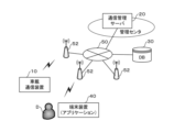
- FIG. 1 is a schematic diagram showing an example of the configuration of a communication management system according to the first embodiment of the present disclosure
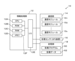
- FIG. 2 is a block diagram showing an example of the electrical configuration of an in-vehicle communication device
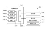
- FIG. 3 is a block diagram showing an example of the electrical configuration of the communication management server
- FIG. 4 is a state transition diagram of the communication module
- FIG. 5 is a functional block diagram showing an example of the functional configuration of each part of the communication management system according to the first embodiment of the present disclosure
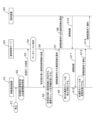
- FIG. 6 is a sequence diagram showing an example of an overview of the processing procedure of the communication management system of the present disclosure
- FIG. 1 is a schematic diagram showing an example of the configuration of a communication management system according to the first embodiment of the present disclosure
- FIG. 2 is a block diagram showing an example of the electrical configuration of an in-vehicle communication device
- FIG. 3 is a block diagram showing an example of the electrical configuration of the communication management server
- FIG. 4 is a state transition diagram of the communication module
- FIG. 7 is a sequence diagram showing another example of the outline of the processing procedure of the communication management system of the present disclosure
- FIG. 8 is a chart showing an example of a table for managing individual data collected from vehicles
- FIG. 9 is a schematic diagram showing an example of statistical data obtained from the database
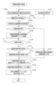
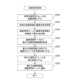
- FIG. 10 is a flowchart showing an example of the procedure of "standby state transition processing" executed by the in-vehicle communication device
- FIG. 11 is a flow chart showing an example of a procedure for handling processing when a trigger is received, which is executed by the in-vehicle communication device
- FIG. 12 is a flowchart showing an example of the procedure of "startup processing"
- FIG. 13 is a flowchart showing an example of the procedure of "line change processing”
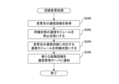
- FIG. 14 is a flowchart showing another example of the procedure of "line change processing”
- FIG. 15 is a flow chart showing an example of a procedure for handling processing when a trigger is received, which is executed by the communication management server
- FIG. 16 is a flow chart showing an example of the procedure of "standby state transition support processing”
- FIG. 17 is a chart showing an example of an activation line registration table
- FIG. 18 is a flowchart showing an example of the procedure of "remote activation processing”
- FIG. 19 is a flowchart showing an example of the procedure of "communication status monitoring processing" executed by the communication management server
- FIG. 20 is a graph showing how the communication state fluctuates;
- FIG. 20 is a graph showing how the communication state fluctuates
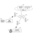
- FIG. 21 is a schematic diagram showing an example of the configuration of a communication management system according to the second embodiment of the present disclosure
- FIG. 22 is a functional block diagram showing an example of the functional configuration of each part of the communication management system according to the second embodiment of the present disclosure
- FIG. 23 is a flowchart showing an example of the procedure of "standby state transition processing" according to the second embodiment of the present disclosure
- FIG. 24 is a schematic diagram showing an example of the configuration of a communication management system according to the third embodiment of the present disclosure
- FIG. 25 is a functional block diagram showing an example of the functional configuration of each part of the communication management system according to the third embodiment of the present disclosure
- FIG. 26 is a flowchart showing an example of the procedure of "standby state transition processing” according to the third embodiment of the present disclosure
- FIG. 27 is a flowchart illustrating an example of a procedure of "remote activation processing” according to the third embodiment of the present disclosure
- the communication management system of the present disclosure includes an in-vehicle communication device 10 mounted on a vehicle, a communication management server 20 installed in a management center, and a database connected to the communication management server 20 (hereinafter referred to as abbreviated as “DB”) 30 and a terminal device 40 used by the user D.
- the vehicle may be an automatically driven vehicle that runs autonomously, or a general vehicle that is driven by the user D.
- the in-vehicle communication device 10 and the terminal device 40 are connected via a wireless base station 52 to a network 50 that is a public network such as the Internet.
- the in-vehicle communication device 10 wirelessly communicates with the communication management server 20 connected to the network 50 .
- the communication management server 20 and the DB 30 are connected via a LAN or the like, and perform wired or wireless communication.
- the communication management system of the present disclosure is a system that remotely activates the vehicle-mounted communication device 10 that has shifted to the power saving mode from the communication management server 20 .
- the communication management server 20 is a server that manages a plurality of in-vehicle communication devices 10, manages each in-vehicle communication device 10, and remotely activates each in-vehicle communication device 10 even after the in-vehicle communication device 10 shifts to the power saving mode. keep it possible.
- in-vehicle communication device 10 one communication management server 20, one DB 30, and one terminal device 40 are illustrated, the number of each device is not limited to the illustrated example. From the viewpoint of constructing the DB 30, it is assumed that there are a plurality of vehicles, that is, a plurality of in-vehicle communication devices 10 . A plurality of communication management servers 20, DBs 30, and terminal devices 40 may also be arranged.
- the installation location of the communication management server 20 and the DB 30 is merely an example, and may be installed on the cloud, for example.
- the terminal device 40 may be omitted.
- the terminal device 40 stores an application program for remote activation, and the communication management server 20 issues a activation request to the in-vehicle communication device 10 based on the activation instruction from the terminal device 40.
- the management server 20 may decide by itself whether or not to issue an activation request.
- the in-vehicle communication device 10 is an electronic control unit (ECU: Electronic Control Unit) or the like, and includes an information processing section 12, a communication section 14, various sensors 16, and a storage section 18, which are computers.
- the information processing unit 12 includes a CPU (Central Processing Unit) 12A, a ROM (Read Only Memory) 12B, a RAM (Random Access Memory) 12C, a nonvolatile memory 12D, and an input/output unit (I/O) 12E. , are interconnected by a bus 12F.
- Each part of the communication part 14, the various sensors 16, and the storage part 18 is connected to the I/O 120E.
- the CPU 12A reads the program from the storage unit 18 and executes the program using the RAM 12C as a work area.
- the CPU 12A performs control of each unit connected to the I/O 12E and various arithmetic processing according to programs stored in the storage unit 18 .
- Various sensors 16 include a GPS (Global Positioning System) device that acquires the current position of the vehicle, an on-board camera that captures images of the vehicle's surroundings such as the front and sides of the vehicle, and obstacles around the vehicle.
- GPS Global Positioning System
- a millimeter wave radar, LIDAR (Light Detection and Ranging/Laser Imaging Detection and Ranging), a microphone for collecting sounds around the vehicle, and the like may be included. Since this disclosure primarily uses GPS devices, they will be referred to hereinafter as GPS devices 16 .
- the communication unit 14 is a communication interface for communicating with the outside (for example, the communication management server 20).
- the outside for example, standards such as Ethernet (registered trademark), FDDI, and Wi-Fi (registered trademark), and wide-area wireless communication standards such as LTE (Long Term Evolution), 4G, and 5G are used.
- the communication unit 14 also includes a plurality of communication modules 15 1 to 15 n each of which can be independently controlled.
- a plurality of communication modules 15 1 to 15 n are provided corresponding to each of a plurality of available communication service providers (carriers), and use different communication lines.
- the plurality of communication modules 15 1 to 15 n are collectively referred to as communication modules 15 when there is no need to distinguish between them.
- the storage unit 18 is an external storage device such as an HDD (Hard Disk Drive). Various programs and various data are stored in the storage unit 18 . In this embodiment, the storage unit 18 stores various programs 60 and various data 62 for executing "standby state transition processing", “startup processing”, and “line change processing”, which will be described later.
- HDD Hard Disk Drive
- the on-vehicle communication device 10 When mounted on a general vehicle, the on-vehicle communication device 10 may be equipped with various user interfaces that are so-called HMI (Human Machine Interface). In addition, when mounted in an automatic driving vehicle, the in-vehicle communication device 10 may further include a vehicle control unit for controlling each mechanism of the vehicle to achieve automatic driving and remote control.
- HMI Human Machine Interface
- the communication management server 20 includes an information processing section 22, a communication section 24, and a storage section .
- Each unit of the communication unit 24 and the storage unit 26 is connected to the I/O 22E.
- the information processing unit 22 and the communication unit 24 have the same configuration as the in-vehicle communication device 10, so description thereof will be omitted.
- the storage unit 26 is an external storage device such as an HDD.
- the storage unit 26 stores various programs 64 for executing "standby state shift support processing”, “remote activation processing”, and “communication status monitoring processing”, which will be described later, and various data 66 such as activation line registration tables. ing.
- the terminal device 40 has the same configuration as the communication management server 20 except that it has an operation display unit as a user interface.
- Each communication module 15, as shown in FIG. 4, has three states: a remote activation standby state (hereinafter referred to as "standby state"), an activated state, and a stopped state.
- the communication module 15 is controlled by the information processing unit 12, and when a standby instruction signal is input, the communication module 15 shifts from the activated state to the standby state, and when the activation instruction signal is input, transitions from the standby state to the activated state. Further, the communication module 15 is in a stopped state when the power is turned off, and is in an active state when the power is turned on.
- the remote activation standby state is a state of waiting for an activation request from the communication management server 20 to become activated.
- the standby state the power of the communication module 15 is on, but data communication cannot be performed because of the power saving mode.
- the activated state is a state in which data communication is possible and the power is on.
- a stopped state is a state in which the power is off and data communication cannot be performed.
- the in-vehicle communication device 10 includes a communication state detection section 70 and a power control section 72 .
- the communication state detection unit 70 and the power supply control unit 72 are realized by executing various programs described later on the in-vehicle communication device 10 side.
- the communication state detection unit 70 detects the communication state of multiple communication lines used by the communication unit 14 . Specifically, the communication state detection unit 70 acquires from the communication unit 14 one of the parameters representing the communication state such as the radio wave intensity measured by the communication unit 14 . Note that the parameters representing the communication state will be described later. Also, the communication state detection unit 70 acquires the current position information of the vehicle from the GPS device 16 . The power control unit 72 controls switching of the states of the plurality of communication modules 15 of the communication unit 14 and controls power supply to the plurality of communication modules 15 .
- the power control unit 72 puts some of the communication modules 15 corresponding to the communication lines used for remote activation (hereinafter referred to as "activation lines") into a standby state, and puts the remaining communication modules 15 into a stopped state.
- activation lines may be used for remote activation, in which case a plurality of communication modules 15 corresponding to the plurality of activation lines are placed in a standby state.
- the power control unit 72 notifies the communication management server 20 of the activation line.
- the communication management server 20 includes an information collection unit 74, an activation line candidate notification unit 76, a remote activation unit 78, and a communication status monitoring unit 80.
- An information collection unit 74, an activation line candidate notification unit 76, a remote activation unit 78, and a communication status monitoring unit 80 are realized by executing various programs described later on the communication management server 20 side.
- the information collection unit 74 collects information about the communication state at each parking point (hereinafter referred to as "communication state information") from each of the plurality of in-vehicle communication devices 10 and stores it in the DB 30 .
- the activation line candidate notification unit 76 refers to the information in the DB 30 and selects the activation line candidates. A plurality of activation line candidates may be selected.
- the activation line candidate notification unit 76 notifies the selected activation line candidate to the in-vehicle communication device 10 .
- the communication status information includes parameter values that represent the communication status.
- Parameters representing the communication state include radio wave intensity, congestion state, throughput, latency, and the like.
- the stability of the communication line is determined using any one of the listed parameters as an index.
- the congestion state represents the degree of congestion
- the throughput represents the amount of data that can be transmitted per unit time
- the latency represents the delay time. For example, when the congestion state and latency are used as indicators, the stability of the communication line represents the speed of the communication speed.
- the individual data collected from the in-vehicle communication device 10, that is, the parking position and time, the communication status of all available communication lines (for example, the radio wave intensity of each communication line A, B, C) ) are accumulated in the DB 30 in the form of a table, for example.
- the accumulated data can be used as statistical data.
- FIG. 9 it is possible to obtain from the DB 30 representative values (for example, average values, maximum values, minimum values, etc.) of parameters representing the communication state for each time zone.
- FIG. 9 shows the prediction of changes in radio wave intensity for 24 hours in Chiyoda-ku, Tokyo.
- the radio field strength of the communication line A is low and the communication state is unstable, but in the afternoon the radio field strength is high and the communication state is stable.
- the communication state of each communication line fluctuates under the influence of, for example, the congestion state of the base station, but the fluctuation trend can be predicted from statistical data.
- the data from the area where the communication failure occurred is accumulated, so it is possible to grasp the fluctuation trend of the communication state in real time until recovery.
- the remote activation unit 78 remotely activates each communication module of the in-vehicle communication device 10 via the notified activation line according to the activation instruction from the terminal device 40 . If there are multiple activation lines, each communication module is remotely activated via at least one activation line.
- the communication state monitoring unit 80 refers to the information in the DB 30 and monitors the communication state of the activation line notified from the in-vehicle communication device 10 . When the communication state of the notified activation line is likely to deteriorate, the remote activation unit 78 requests the in-vehicle communication device 10 to change the activation line.
- the processing of the communication management system of the present disclosure starts when the in-vehicle communication device 10 stops moving due to parking of the vehicle (S1).
- the communication state detection unit 70 detects the communication state of a plurality of communication lines from the communication unit 14, and acquires the current position information of the vehicle from the GPS device 16 (S2).
- the acquired communication state information and location information are transmitted to the communication management server 20 (S3).
- the information collection unit 74 associates the communication status information and the location information with the time and saves them in the DB 30 (S4).
- the activation line candidate notifying unit 76 identifies the parking area from the position information, refers to the DB 30, and from the identified area and time zone, the communication state is good, that is, the communication line is more stable than the other communication lines.
- Information on the communication line is obtained and transmitted to the in-vehicle communication device 10 (S5). The in-vehicle communication device 10 is notified of the activation line candidate.
- the power control unit 72 determines the notified activation line candidate, that is, the communication line with higher stability than the other communication lines, as the activation line, and the communication module corresponding to the activation line is switched to the power source. remains ON and enters a standby state (S6).
- the power control unit 72 notifies the communication management server 20 of which communication line is to be used for remote activation standby (S7).
- the communication management server 20 also notifies the terminal device 40 of which communication line is waiting for remote activation (S8).
- the power control unit 72 powers off the rest of the communication modules to stop them (S9). Then, the in-vehicle communication device 10 shifts to the power saving mode and waits for remote activation from the communication management server 20 .
- a startup instruction is sent from the terminal device 40 to the communication management server 20 (S10).
- the remote activation unit 78 receives the activation instruction from the terminal device 40, it transmits an activation request to the in-vehicle communication device 10 via the activation line (S11).
- the power control unit 72 activates all communication modules (S12), and transmits a remote activation completion notification to the communication management server 20 (S13).
- the communication management server 20 also notifies the terminal device 40 of completion of remote activation (S14).
- the communication management server 20 requests the in-vehicle communication device 10 to change the activation line when the communication state of the activation line deteriorates. The flow of processing in that case will be described with reference to FIG.
- the communication status monitoring unit 80 refers to the information in the DB 30, and for each of the in-vehicle communication devices 10 notified of the activation line, the communication status of the activation line deteriorates. It is periodically checked whether or not the device has been installed (S20). Then, when the communication condition of the activation line is likely to deteriorate in the future, the remote activation unit 78 transmits a line change request requesting a change of the activation line to the in-vehicle communication device 10 via the activation line (S21).
- all communication modules are remotely activated as described below.
- the power control unit 72 activates all communication modules in response to the line change request (S22), and transmits a preparation completion notification to the communication management server 20 (S23). That is, the in-vehicle communication device 10 is once remotely activated by the judgment of the management center.
- the activation line candidate notification unit 76 refers to the DB 30, acquires information on a communication line with a high degree of stability, and transmits the information to the in-vehicle communication device 10 (S24). The in-vehicle communication device 10 is notified of the new activation line candidate.
- the power control unit 72 determines the notified activation line candidate, that is, the communication line with high stability, as the activation line, and keeps the communication module corresponding to the activation line in the standby state while the power is on. (S25).
- the power control unit 72 powers off the rest of the communication modules to bring them into a stopped state (S26).
- the power control unit 72 notifies the communication management server 20 of which communication line is to be used for remote activation standby (S27).
- the communication management server 20 also notifies the terminal device 40 of which communication line is waiting for remote activation (S28). Then, the in-vehicle communication device 10 shifts to the power saving mode again and waits for remote activation from the communication management server 20 .
- step S100 the CPU 12A acquires the communication status of all communication lines.
- step S102 the CPU 12A determines whether or not there is a line through which communication with the communication management server 20 is possible. If there is a communicable line, the process proceeds to step S104, and if there is no communicable line, the process proceeds to step S122.
- step S104 the CPU 12A tries to acquire the position information of the host vehicle from the GPS device 16. FIG.
- step S122 instruct to change the parking location, and return to step S100.
- Communication with the communication management server 20 cannot be performed when there is no connected communication line, such as when all carriers are out of service. For this reason, a general vehicle issues a warning to the driver, and an autonomous vehicle instructs the vehicle control unit to change the parking location.
- step S106 the CPU 12A determines whether or not position information has been acquired from the GPS device 16. If the position information could be obtained, the process proceeds to step S108, and if the position information could not be obtained, the process proceeds to step S124.
- step S108 the CPU 12A controls the communication section 14 to transmit the communication state information and the location information to the communication management server 20.
- step S110 the CPU 12A repeatedly determines whether or not a reply has been received from the communication management server 20 until a reply is received.
- the communication management server 20 may not be able to select the activation line candidate because the data in the parking area does not exist in the DB 30 or the like. In this case, the communication management server 20 notifies that the activation line candidate cannot be selected.
- step S112 the CPU 12A determines whether or not the activation line candidate has been acquired from the communication management server 20. If the activation line candidate could be obtained, the process proceeds to step S114, and if the activation line candidate could not be obtained from the communication management server 20, the process proceeds to step S124.
- step S114 the CPU 12A determines the candidate communication line as the activation line.
- step S124 the CPU 12A refers to the communication status of all the communication lines obtained in step S100, and determines whether the communication status is Determine the best communication line to be the activation line.
- step S116 the CPU 12A puts the communication module corresponding to the activated line into the standby state, in the following step S118, notifies the communication management server 20 of the activated line, and in the following step S120, the rest of the communication modules are placed in the stopped state. to end the routine.
- step S200 when the CPU 12A of the in-vehicle communication device 10 receives any trigger signal, it determines in step S200 whether or not a remote activation request has been received. When the remote activation request is received, the process proceeds to step S202, and "activation processing" is executed in step S202. On the other hand, if the remote activation request has not been received, since the line change request has been received, the process proceeds to step S204, and the "activation line change process" is executed in step S204.
- step S210 the CPU 12A activates all communication modules in response to the activation request.
- step S212 the CPU 12A controls the communication unit 14 to transmit a remote activation completion notification to the communication management server 20, and terminates the routine.
- step S220 the CPU 12A activates all communication modules in response to the line change request.
- step S222 the CPU 12A acquires the communication status of all communication lines.
- step S224 the CPU 12A controls the communication unit 14 to transmit the communication state information and the preparation completion notification to the communication management server 20.
- step S226 the CPU 12A acquires a new activation line candidate from the communication management server 20.
- step S232 the CPU 12A notifies the communication management server 20 of the new activation line, and terminates the routine.
- the in-vehicle communication device 10 acquires the communication status of all communication lines and transmits the communication status information to the communication management server 20 even when the line is changed. It's for.
- the communication management server 20 may designate the communication line to be changed in advance and request the line change.
- FIG. 14 shows the procedure of line change processing in this case.
- step S240 the CPU 12A acquires the communication line to be changed.
- step S242 the CPU 12A stops the communication module in the standby state.
- step S244 the CPU 12A puts the communication module corresponding to the communication line to be changed into a standby state.
- step S246 the CPU 12A notifies the communication management server 20 of the new activation line, and terminates the routine.
- step S310 when the CPU 22A receives the communication state information and the location information, it stores the communication state information and the location information in the DB 30 in association with the time.
- step S312 the CPU 22A refers to the DB 30 and selects an activation line candidate based on the area and time period according to the location information.
- step S314 the CPU 22A controls the communication unit 24 to notify the in-vehicle communication device 10 of the selected activation line candidate.
- step S316 the CPU 22A determines whether or not an activation line notification has been received from the in-vehicle communication device 10. If the activation line notification has been received, in step S318, the CPU 22A associates the received activation line with the vehicle. and exit the routine.
- the storage unit 26 of the communication management server 20 stores, for example, an activation line registration table.
- the activation line registration table stores the relationship between vehicle identification information (for example, vehicle ID), parking position, and standby line in the form of a table.
- vehicle identification information for example, vehicle ID
- parking position for example, parking position
- standby line in the form of a table.
- a wake-up line notification is received, a new relationship is added to this wake-up line registration table.
- the in-vehicle communication device 10 is remotely activated, there is no need to manage the activation line, so the corresponding relationship is deleted from the table.
- step S320 the CPU 22A controls the communication unit 24 in response to the activation instruction from the terminal device 40 to transmit an activation request to the in-vehicle communication device 10 via the activation line.
- step S322 the CPU 22A determines whether or not the activation completion notification has been received from the in-vehicle communication device 10. If the activation completion notification has been received, in step S324, the CPU 22A controls the communication unit 24 to The device 40 is caused to transmit a boot completion notification, and the routine ends.
- step S400 the CPU 22A selects one target vehicle from the activation line registration table. As described above, the in-vehicle communication device 10 is in one-to-one correspondence with the vehicle.
- step S402 the CPU 22A predicts the communication state of the activation line after a predetermined time (for example, one hour) has passed in the parking area of the vehicle.
- step S404 the CPU 22A determines whether communication with the communication management server 20 is possible through the activation line. If the activation line cannot communicate, the process proceeds to step S406. On the other hand, if communication is possible through the activation line, there is no need to change the activation line, so the process proceeds to step S418.
- the index representing the communication state is the radio wave intensity.
- the radio wave intensity of each communication line fluctuates with time, and communication cannot be performed when the radio wave intensity is below the threshold. For example, assume that there is a vehicle with a communication line B as the activation line. After a predetermined time has elapsed from the present time, the radio wave intensity of the communication line B becomes equal to or less than the threshold value, and communication with the communication management server 20 cannot be performed on the communication line B.
- step S406 the CPU 22A controls the communication unit 24 to transmit a line change request to the in-vehicle communication device 10.
- step S408 the CPU 22A determines whether or not it has received a notification of the completion of preparation. A communication line to be changed to is selected, and in subsequent step S412, the vehicle-mounted communication device 10 is notified of a new activation line candidate.
- step S414 the CPU 22A determines whether or not an activation line notification has been received from the in-vehicle communication device 10. If the activation line notification has been received, in step S416 the received activation line is associated with the vehicle. to register. For example, the activation line column of the activation line registration table shown in FIG. 17 is updated. Next, in step S418, the CPU 22A determines whether or not there is a next vehicle. If there is a next vehicle, the process returns to step S400, and if there is no next vehicle, the routine ends. In this way, the communication state of the activation line is checked one by one for each vehicle that manages the activation line.
- the in-vehicle communication device shifts to the power saving mode by putting some communication modules corresponding to communication lines in good communication state into the standby state. state can be maintained. In addition, since other communication modules are put in the stopped state, power consumption can be suppressed as compared with the case where all communication modules are put in the standby state.
- the communication management server can utilize the information in the database to select a communication line with a good communication state in a specific area and at a specific time, either now or after the elapse of a predetermined period of time.
- the communication management server can reliably remotely activate the on-board communication device via the activation line. Furthermore, the communication management server periodically checks the communication status of the activation line notified from the in-vehicle communication device, and requests the in-vehicle communication device to change the activation line when the communication status of the activation line deteriorates. It is possible to maintain a remote start-up state regardless of fluctuations in the communication state of each communication line.
- the communication management system according to the second embodiment is the same as the first embodiment except that the DB 30 is arranged on the network 50 so that it can be directly accessed from the vehicle-mounted communication device 10. Therefore, the same components are denoted by the same reference numerals, the description thereof is omitted, and only the differences are described.
- the DB 30 in this case may be a database server, a file server, or a NAS (Network Attached Storage).
- the in-vehicle communication device 10 includes a communication state detection section 70 and a power control section 72 .
- the communication management server 20 has a remote starter 78 and a communication status monitor 80 .
- the functions of the remote starter 78 and the communication status monitor 80 are the same as in the first embodiment.
- the communication state detection unit 70 acquires the communication states of multiple communication lines and the current position information of the vehicle. Also, the communication state detection unit 70 stores the location information and the communication state information in the DB 30 .
- the power supply control unit 72 refers to the information in the DB 30 and tries to acquire an activation line candidate, and determines the activation line. In the power saving mode, the power control unit 72 puts some of the communication modules 15 corresponding to the activation line into the standby state, and puts the rest of the communication modules 15 into the stop state. Then, the power control unit 72 notifies the communication management server 20 of the activation line.
- step S508 the CPU 12A controls the communication unit 14 to transmit the communication state information and the location information to the DB30.
- step S510 the CPU 12A directly accesses the DB 30 and acquires activation line candidates based on the area and time period according to the location information.
- the in-vehicle communication device in addition to being able to obtain the same effect as the first embodiment, it is possible to directly access the database from the vehicle-mounted communication device and acquire activation line candidates. Therefore, the in-vehicle communication device can shift to the power saving mode without waiting for a response from the communication management server.
- the in-vehicle communication device 10 has a dedicated DB 32 .
- the dedicated DB 32 may be arranged outside the information processing section 22, and may be stored in the storage section 18, which is an external storage device, for example.
- the dedicated DB 32 stores communication status information and position information acquired by the own vehicle at the time of parking in association with the time zone.
- the power control unit 72 of the on-vehicle communication device 10 refers to the information in the dedicated DB 32 and selects an activation line candidate.
- the power supply control unit 72 puts some of the communication modules 15 corresponding to the communication lines of the activation line candidates into the standby state, and puts the remaining communication modules 15 into the stop state.
- the remote activation unit 78 of the communication management server 20 remotely activates each communication module of the in-vehicle communication device 10 via all communication lines.
- step S600 the CPU 12A acquires the communication status of all communication lines.
- step S602 the CPU 12A determines whether or not there is a communicable line. If there is a communicable line, the process proceeds to step S604, and if there is no communicable line, an instruction to change the parking location is given in step S616, and the process returns to step S600.
- step S604 the CPU 12A acquires position information of the own vehicle from the GPS device 16.
- step S606 the CPU 12A stores the communication status information and location information in the dedicated DB32.
- step S608 the CPU 12A refers to the dedicated DB 32 and selects an activation line candidate based on the area and time period according to the location information.
- step S610 the CPU 12A determines the activation line candidate communication line as the activation line.
- step S612 the CPU 12A puts the communication module corresponding to the activation line into the standby state, and in the following step S614, puts the remaining communication modules into the stop state, and ends the routine.
- step S700 the CPU 22A controls the communication unit 24 in response to an activation instruction from the terminal device 40 to transmit an activation request to the in-vehicle communication device 10 through all communication lines.
- step S702 the CPU 22A determines whether or not the activation completion notification has been received from the in-vehicle communication device 10. If the activation completion notification has been received, in step S704, the CPU 22A controls the communication unit 24 to The terminal device 40 is made to transmit a start-up completion notification, and the routine ends.
- the vehicle-mounted communication device when communication is possible, the same effect as in the first embodiment can be obtained.
- the vehicle-mounted communication device can be activated by transmitting a activation request to the vehicle-mounted communication device through all the communication lines.
- the communication management server may select a communication line with the most stable communication state from the communication state history in the database, and transmit an activation request to the in-vehicle communication device.
- the communication management server may select a communication line with a high communication speed and transmit an activation request to the in-vehicle communication device.
- the information of the activation line candidate that is, the information of the highly stable communication line is obtained directly from the DB 30 or via the communication management server. It is also possible to acquire from other companies through (V2V) and mesh communication networks.
- processing flow of the program described in the above embodiment is also an example, and unnecessary steps may be deleted, new steps added, or the processing order changed without departing from the spirit.
- processing according to the embodiment is realized by a software configuration using a computer by executing a program, but the present invention is not limited to this.
- processing may be realized by a hardware configuration or a combination of a hardware configuration and a software configuration.
- processors other than the CPU may execute the program that the CPU reads and executes the software (program) in the above embodiment.
- the processor is PLD (Programmable Logic Device) whose circuit configuration can be changed after manufacturing such as FPGA (Field-Programmable Gate Array), and ASIC (Application Specific Integrated Circuit) to execute specific processing.
- PLD Programmable Logic Device
- FPGA Field-Programmable Gate Array
- ASIC Application Specific Integrated Circuit
- each of the above programs may be executed by one of these various processors, or a combination of two or more processors of the same or different type (for example, a plurality of FPGAs and a combination of a CPU and an FPGA). etc.). More specifically, the hardware structure of these various processors is an electric circuit in which circuit elements such as semiconductor elements are combined.
- each of the above embodiments the mode in which the program is pre-stored (installed) in the storage unit has been described, but the present invention is not limited to this.
- Programs are stored on non-transitory storage media such as CD-ROM (Compact Disk Read Only Memory), DVD-ROM (Digital Versatile Disk Read Only Memory), USB (Universal Serial Bus) memory, semiconductor memory, etc. may be provided in any form.
- each of the above programs may be downloaded from an external device via a network.
Landscapes
- Engineering & Computer Science (AREA)
- Computer Networks & Wireless Communication (AREA)
- Signal Processing (AREA)
- Theoretical Computer Science (AREA)
- General Engineering & Computer Science (AREA)
- Physics & Mathematics (AREA)
- General Physics & Mathematics (AREA)
- Computer Security & Cryptography (AREA)
- Computer Hardware Design (AREA)
- Computing Systems (AREA)
- Mobile Radio Communication Systems (AREA)
- Power Sources (AREA)
- Small-Scale Networks (AREA)
- Cable Transmission Systems, Equalization Of Radio And Reduction Of Echo (AREA)
Abstract
車載通信装置は、互いに異なる複数の通信回線に対応する複数の通信モジュールを含む通信部と、車両の停止時に、複数の通信回線各々の通信状態に基づいて通信管理サーバからの遠隔起動に使用する起動回線を少なくとも1つ決定し、起動回線に対応する一部の通信モジュールへの電源からの電力の供給を維持したままで一部の通信モジュールを通信管理サーバからの要求信号のみを受信可能な待機状態とすると共に、残りの通信モジュールへの電源からの電力の供給を遮断して前記残りの通信モジュールを停止状態とする電源制御部と、を備えている。
Description
本出願は、2021年12月28日に出願された日本出願番号2021-214979号に基づくものであって、その優先権の利益を主張するものであり、その特許出願のすべての内容が、参照により本明細書に組み入れられる。
本開示は、車載通信装置、通信管理サーバ、プログラム、通信管理システム及び通信管理方法に関する。
各種機器では、一部の機能を停止させて電力の消費を抑制する省電力モードを備えるものが知られている。また、遠隔操作により省電力モードから復帰させる技術も知られている。例えば、特許文献1には、通信インターフェイスを複数持つ情報処理装置において、どの通信インターフェイスを介して起動パケットを受信したとしても省電力状態から復帰できるようにするために、各通信インターフェイスの識別情報を記憶しておき、何れの通信インターフェイスから受信した起動パケットであっても、起動パケットに含まれる識別情報が記憶した識別情報と合致するものであれば省電力状態から復帰させる技術が開示されている。
しかしながら、発明者の詳細な検討の結果、上記技術を車載通信装置に適用した場合に、以下のような課題が見出された。まず、セルラー通信回線を用いる場合、回線状態は、エリアや時間帯により変動するため、駐車場所によっては遠隔起動できない場合がある。また、複数の通信モジュールに電力を供給したまま省電力モードに移行したのでは、消費電力が高くなり、車両のバッテリ上がりが懸念される。
本開示の目的は、遠隔起動可能な状態を維持しつつ、全部の通信モジュールを待機状態とする場合に比べて消費電力を抑えることができる、車載通信装置、通信管理サーバ、通信管理システム及びプログラムを提供することにある。
本開示の一態様による車載通信装置は、互いに異なる複数の通信回線に対応する複数の通信モジュールを含む通信部と、車両の停止時に、前記複数の通信回線各々の通信状態に基づいて通信管理サーバからの遠隔起動に使用する起動回線を少なくとも1つ決定し、前記起動回線に対応する一部の通信モジュールへの電源からの電力の供給を維持したままで前記一部の通信モジュールを前記通信管理サーバからの要求信号のみを受信可能な待機状態とすると共に、残りの通信モジュールへの前記電源からの電力の供給を遮断して前記残りの通信モジュールを停止状態とする電源制御部と、を備える。
本開示の一態様による通信管理サーバは、互いに異なる複数の通信回線に対応する複数の通信モジュールを含む通信部と、車両の停止時に、前記複数の通信回線各々の通信状態に基づいて通信管理サーバからの遠隔起動に使用する起動回線を少なくとも1つ決定し、前記起動回線に対応する一部の通信モジュールへの電源からの電力の供給を維持したままで前記一部の通信モジュールを前記通信管理サーバからの要求信号のみを受信可能な待機状態とすると共に、残りの通信モジュールへの前記電源からの電力の供給を遮断して前記残りの通信モジュールを停止状態とする電源制御部と、を備えた車載通信装置を管理する通信管理サーバであって、前記複数の通信回線のうちで前記通信状態の安定度が他の通信回線より高い通信回線を起動回線候補として前記車載通信装置に通知する通知部と、前記起動回線を介して起動要求を送信することにより前記車載通信装置を起動する遠隔起動部と、を備える。
本開示の一態様による通信管理システムは、互いに異なる複数の通信回線に対応する複数の通信モジュールを含む通信部と、車両の停止時に、前記複数の通信回線各々の通信状態に基づいて通信管理サーバからの遠隔起動に使用する起動回線を少なくとも1つ決定し、前記起動回線に対応する一部の通信モジュールへの電源からの電力の供給を維持したままで前記一部の通信モジュールを前記通信管理サーバからの要求信号のみを受信可能な待機状態とすると共に、残りの通信モジュールへの前記電源からの電力の供給を遮断して前記残りの通信モジュールを停止状態とする電源制御部と、を備えた車載通信装置と、前記車載通信装置とネットワークを介して通信可能な通信管理サーバであって、前記複数の通信回線のうちで前記通信状態の安定度が他の通信回線より高い通信回線を起動回線候補として前記車載通信装置に通知する通知部と、前記起動回線を介して起動要求を送信することにより前記車載通信装置を起動する遠隔起動部と、を備えた通信管理サーバと、を備える。
本開示の一態様による通信管理方法では、互いに異なる複数の通信回線に対応する複数の通信モジュールを含む通信部を備えた車載通信装置に対し、前記車載通信装置とネットワークを介して通信可能な通信管理サーバから、前記複数の通信回線のうちで通信状態の安定度が他の通信回線より高い通信回線を前記車載通信装置に通知し、前記車載通信装置は、車両の停止時に、通知された前記安定度が他の通信回線より高い通信回線に基づいて通信管理サーバからの遠隔起動に使用する起動回線を少なくとも1つ決定し、前記起動回線に対応する一部の通信モジュールへの電源からの電力の供給を維持したままで前記一部の通信モジュールを前記通信管理サーバからの要求信号のみを受信可能な待機状態とすると共に、残りの通信モジュールへの前記電源からの電力の供給を遮断して前記残りの通信モジュールを停止状態とし、前記通信管理サーバは、前記起動回線を介して起動要求を送信することにより前記車載通信装置を起動する。
本開示についての上記目的およびその他の目的、特徴や利点は、添付の図面を参照しながら下記の詳細な記述により、より明確になる。その図面は、
図1は、本開示の第1の実施形態に係る通信管理システムの構成の一例を示す模式図であり、
図2は、車載通信装置の電気的構成の一例を示すブロック図であり、
図3は、通信管理サーバの電気的構成の一例を示すブロック図であり、
図4は、通信モジュールの状態遷移図であり、
図5は、本開示の第1の実施形態に係る通信管理システムの各部の機能的な構成の一例を示す機能ブロック図であり、
図6は、本開示の通信管理システムの処理手順の概要の一例を示すシーケンス図であり、
図7は、本開示の通信管理システムの処理手順の概要の他の一例を示すシーケンス図であり、
図8は、車両から収集された個別データを管理するテーブルの一例を示す図表であり、
図9は、データベースから取得される統計的データの一例を示す模式図であり、
図10は、車載通信装置によって実行される「待機状態移行処理」の手順の一例を示すフローチャートであり、
図11は、車載通信装置によって実行されるトリガを受信した場合の対応処理の手順の一例を示すフローチャートであり、
図12は、「起動処理」の手順の一例を示すフローチャートであり、
図13は、「回線変更処理」の手順の一例を示すフローチャートであり、
図14は、「回線変更処理」の手順の他の一例を示すフローチャートであり、
図15は、通信管理サーバによって実行されるトリガを受信した場合の対応処理の手順の一例を示すフローチャートであり、
図16は、「待機状態移行支援処理」の手順の一例を示すフローチャートであり、
図17は、起動回線登録テーブルの一例を示す図表であり、
図18は、「遠隔起動処理」の手順の一例を示すフローチャートであり、
図19は、通信管理サーバによって実行される「通信状態監視処理」の手順の一例を示すフローチャートであり、
図20は、通信状態が変動する様子を示すグラフであり、
図21は、本開示の第2の実施形態に係る通信管理システムの構成の一例を示す模式図であり、
図22は、本開示の第2の実施形態に係る通信管理システムの各部の機能的な構成の一例を示す機能ブロック図であり、
図23は、本開示の第2の実施形態に係る「待機状態移行処理」の手順の一例を示すフローチャートであり、
図24は、本開示の第3の実施形態に係る通信管理システムの構成の一例を示す模式図であり、
図25は、本開示の第3の実施形態に係る通信管理システムの各部の機能的な構成の一例を示す機能ブロック図であり、
図26は、本開示の第3の実施形態に係る「待機状態移行処理」の手順の一例を示すフローチャートであり、
図27は、本開示の第3の実施形態に係る「遠隔起動処理」の手順の一例を示すフローチャートである。
以下、図面を参照して本発明の実施の形態を詳細に説明する。
[第1実施形態]
まず、本開示の第1の実施形態に係る通信管理システムについて説明する。
まず、本開示の第1の実施形態に係る通信管理システムについて説明する。
<通信管理システム>
図1に示すように、本開示の通信管理システムは、車両に搭載された車載通信装置10と、管理センタに設置された通信管理サーバ20と、通信管理サーバ20に接続されたデータベース(以下、「DB」と略称する。)30と、利用者Dが使用する端末装置40と、を備えている。車両は、自律的に走行する自動運転車両であってもよく、利用者Dの運転により走行する一般車両であってもよい。
図1に示すように、本開示の通信管理システムは、車両に搭載された車載通信装置10と、管理センタに設置された通信管理サーバ20と、通信管理サーバ20に接続されたデータベース(以下、「DB」と略称する。)30と、利用者Dが使用する端末装置40と、を備えている。車両は、自律的に走行する自動運転車両であってもよく、利用者Dの運転により走行する一般車両であってもよい。
車載通信装置10及び端末装置40は、無線基地局52を介してインターネット等の公衆網であるネットワーク50に接続されている。車載通信装置10は、ネットワーク50に接続された通信管理サーバ20と無線により通信を行う。また、通信管理サーバ20とDB30とは、LAN等で接続されており、有線又は無線により通信を行う。
本開示の通信管理システムは、省電力モードに移行した車載通信装置10を、通信管理サーバ20から遠隔起動するシステムである。通信管理サーバ20は、複数の車載通信装置10を管理するサーバであり、車載通信装置10が省電力モードに移行した後も、各車載通信装置10を管理し、各車載通信装置10を遠隔起動可能な状態に維持する。
なお、車載通信装置10、通信管理サーバ20、DB30及び端末装置40を1つずつ図示しているが、各装置の個数は図示した例に限定されない。DB30構築の観点からは、複数の車両、即ち、複数の車載通信装置10が存在することが前提となる。また、通信管理サーバ20、DB30及び端末装置40もそれぞれ複数個配置されていてもよい。
また、通信管理サーバ20及びDB30の設置場所も一例に過ぎず、例えばクラウド上に配置されていてもよい。さらに、端末装置40は省略してもよい。本実施の形態では、端末装置40には遠隔起動用のアプリケーションプログラムが格納されており、通信管理サーバ20は端末装置40からの起動指示に基づいて車載通信装置10に起動要求を行うが、通信管理サーバ20が起動要求を行うか否かを自ら決定してもよい。
(各装置の電気的構成)
ここで、車載通信装置10の電気的構成の一例について説明する。
図2に示すように、車載通信装置10は、電子制御装置(ECU:Electronic Control Unit)等であり、コンピュータである情報処理部12、通信部14、各種センサ16、及び記憶部18を備えている。情報処理部12は、CPU(Central Processing Unit)12A、ROM(Read Only Memory)12B、RAM(Random Access Memory)12C、不揮発性のメモリ12D、及び入出力部(I/O)12Eを備えており、これら各部はバス12Fにより相互に接続されている。通信部14、各種センサ16、及び記憶部18の各部は、I/O120Eに接続されている。
ここで、車載通信装置10の電気的構成の一例について説明する。
図2に示すように、車載通信装置10は、電子制御装置(ECU:Electronic Control Unit)等であり、コンピュータである情報処理部12、通信部14、各種センサ16、及び記憶部18を備えている。情報処理部12は、CPU(Central Processing Unit)12A、ROM(Read Only Memory)12B、RAM(Random Access Memory)12C、不揮発性のメモリ12D、及び入出力部(I/O)12Eを備えており、これら各部はバス12Fにより相互に接続されている。通信部14、各種センサ16、及び記憶部18の各部は、I/O120Eに接続されている。
CPU12Aは、記憶部18からプログラムを読み出し、RAM12Cを作業領域としてプログラムを実行する。CPU12Aは、記憶部18に記憶されているプログラムにしたがって、I/O12Eに接続されている各部の制御及び各種の演算処理を行う。
各種センサ16としては、自車両の現在位置を取得するGPS(Global Positioning System)装置の外に、車両の前方、側方など車両の周囲を撮影する車載カメラ、車両の周囲の障害物を検知するミリ波レーダやLIDAR(Light Detection and Ranging/Laser Imaging Detection and Ranging)、車両周囲の音声を収集するマイクロフォン等を含んでいてもよい。本開示では、主にGPS装置を使用するため、以下ではGPS装置16と称する。
通信部14は、外部(例えば、通信管理サーバ20)と通信するための通信インタフェースである。外部との通信には、例えば、イーサネット(登録商標)、FDDI、Wi-Fi(登録商標)等の規格、LTE(Long Term Evolution)や4G、5G等の広域無線通信規格が用いられる。また、通信部14は、各々が独立に制御可能な複数の通信モジュール151~15nを備えている。複数の通信モジュール151~15nは、利用可能な複数の通信事業者(キャリア)の各々に対応して設けられ、使用する通信回線がそれぞれ異なっている。複数の通信モジュール151~15nの各々を区別する必要がない場合は、通信モジュール15と総称する。
記憶部18は、HDD(Hard Disk Drive)等の外部記憶装置である。記憶部18には、各種プログラムや各種データが格納されている。本実施の形態では、記憶部18には、後述する「待機状態移行処理」や「起動処理」や「回線変更処理」を実行するための各種プログラム60、各種データ62が格納されている。
なお、一般車両に搭載される場合、車載通信装置10は、いわゆるHMI(Human Machine Interface)である各種ユーザインタフェースを備えていてもよい。また、自動運転車両に搭載される場合、車載通信装置10は、車両の各機構を制御して自動運転や遠隔操縦を実現するための車両制御部をさらに備えていてもよい。
次に、通信管理サーバ20の電気的構成の一例について説明する。
図3に示すように、通信管理サーバ20は、情報処理部22、通信部24、及び記憶部26を備えている。サーバコンピュータである情報処理部22は、CPU22A、ROM22B、RAM22C、不揮発性のメモリ22D、及び入出力部(I/O)22Eを備えており、これら各部はバス22Fにより相互に接続されている。通信部24及び記憶部26の各部は、I/O22Eに接続されている。
図3に示すように、通信管理サーバ20は、情報処理部22、通信部24、及び記憶部26を備えている。サーバコンピュータである情報処理部22は、CPU22A、ROM22B、RAM22C、不揮発性のメモリ22D、及び入出力部(I/O)22Eを備えており、これら各部はバス22Fにより相互に接続されている。通信部24及び記憶部26の各部は、I/O22Eに接続されている。
情報処理部22及び通信部24は、車載通信装置10と同様の構成であるため説明を省略する。記憶部26は、HDD等の外部記憶装置である。記憶部26には、後述する「待機状態移行支援処理」や「遠隔起動処理」や「通信状態監視処理」を実行するための各種プログラム64や、起動回線登録テーブル等の各種データ66が格納されている。
なお、端末装置40の電気的構成の説明は省略する。端末装置40は、ユーザインタフェースとしての操作表示部を備える以外は、通信管理サーバ20と同様の構成である。
(システムの機能構成)
次に、図4~図7を参照して、システムの機能構成について説明する。
次に、図4~図7を参照して、システムの機能構成について説明する。
まず、通信モジュール15の状態遷移について説明する。
各通信モジュール15は、図4に示すように、遠隔起動待機状態(以下、「待機状態」という。)、起動状態、及び停止状態という3つの状態を有する。通信モジュール15は、情報処理部12により制御され、待機指示信号が入力されると、起動状態から待機状態に移行し、起動指示信号が入力されると、待機状態から起動状態に移行する。また、通信モジュール15は、電源がオフにされると停止状態となり、電源がオンにされると起動状態になる。
各通信モジュール15は、図4に示すように、遠隔起動待機状態(以下、「待機状態」という。)、起動状態、及び停止状態という3つの状態を有する。通信モジュール15は、情報処理部12により制御され、待機指示信号が入力されると、起動状態から待機状態に移行し、起動指示信号が入力されると、待機状態から起動状態に移行する。また、通信モジュール15は、電源がオフにされると停止状態となり、電源がオンにされると起動状態になる。
遠隔起動待機状態とは、通信管理サーバ20からの起動要求を受信して起動状態になるのを待機する状態である。待機状態では、通信モジュール15の電源はオンの状態であるが、省電力モードであるためデータ通信は行うことができない。起動状態とは、データ通信が可能な状態で、電源もオンの状態である。停止状態とは、電源がオフの状態であり、データ通信を行うことができない。
次に、図5を参照してシステムの機能構成について説明する。
車載通信装置10は、通信状態検出部70及び電源制御部72を備えている。車載通信装置10側で後述する各種プログラムが実行されることにより通信状態検出部70及び電源制御部72が実現される。
車載通信装置10は、通信状態検出部70及び電源制御部72を備えている。車載通信装置10側で後述する各種プログラムが実行されることにより通信状態検出部70及び電源制御部72が実現される。
通信状態検出部70は、通信部14が使用する複数の通信回線の通信状態を検出する。具体的には、通信状態検出部70は、通信部14で計測された電波強度など通信状態を表すパラメータの1つを通信部14から取得する。なお、通信状態を表すパラメータについては後述する。また、通信状態検出部70は、GPS装置16から車両の現在の位置情報を取得する。電源制御部72は、通信部14の複数の通信モジュール15の状態の切り替えを制御すると共に、複数の通信モジュール15への電力の供給を制御する。
電源制御部72は、省電力モードでは、遠隔起動に使用する通信回線(以下、「起動回線」という。)に対応する一部の通信モジュール15を待機状態にし、残りの通信モジュール15を停止状態にする。複数の起動回線を遠隔起動に使用してもよく、その場合は、複数の起動回線に対応する複数の通信モジュール15を待機状態にする。電源制御部72は、起動回線を通信管理サーバ20に通知する。
通信管理サーバ20は、情報収集部74、起動回線候補通知部76、遠隔起動部78、及び通信状態監視部80を備えている。通信管理サーバ20側で後述する各種プログラムが実行されることにより情報収集部74、起動回線候補通知部76、遠隔起動部78、及び通信状態監視部80の各々が実現される。
情報収集部74は、複数の車載通信装置10の各々から各駐車地点での通信状態に関する情報(以下、「通信状態情報」という。)を収集してDB30に格納する。起動回線候補通知部76は、DB30の情報を参照して起動回線の候補を選定する。起動回線候補は、複数選定されてもよい。起動回線候補通知部76は、選定した起動回線候補を車載通信装置10に通知する。
通信状態情報には、通信状態を表すパラメータの値が含まれる。通信状態を表すパラメータとしては、電波強度、輻輳状態、スループット、レイテンシ等がある。本実施の形態では、列挙したパラメータのうちの何れか1つを指標として通信回線の安定度を判断する。輻輳状態は混雑度合いを表し、スループットは単位時間あたりに伝送できるデータ量を表し、レイテンシは遅延時間を表す。例えば、輻輳状態やレイテンシを指標とする場合、通信回線の安定度は、通信速度の速さを表すことになる。
図8に示すように、車載通信装置10から収集された個別データ、即ち、駐車した位置や時刻、利用可能な全部の通信回線の通信状態(例えば、通信回線A、B、C各々の電波強度)は、例えばテーブルの形式でDB30に蓄積されてゆく。多くのデータがDB30に蓄積されることで、蓄積されたデータは統計的データとして利用できるようになる。例えば、図9に示すように、DB30から、特定のエリアについての通信状態を表すパラメータの時間帯毎の代表値(例えば、平均値、最大値、最小値など)を得ることができる。
図9に示す例は、東京都千代田区についての電波強度の24時間の変化予測を示す。通信回線Aは、午前中は電波強度が低く通信状態が不安定であるが、午後には電波強度が高くなり通信状態が安定する。このように、各通信回線の通信状態は、例えば基地局の混雑状況等の影響を受けて変動するが、その変動傾向は統計的データから予測することができる。また、一時的な通信障害が発生した場合にも、通信障害が発生したエリアからのデータが蓄積されることで、復旧までの通信状態の変動傾向をリアルタイムに把握することができる。
遠隔起動部78は、端末装置40からの起動指示に応じて、通知された起動回線を介して車載通信装置10の各通信モジュールを遠隔起動する。複数の起動回線がある場合は、そのうちの少なくとも1つの起動回線を介して各通信モジュールを遠隔起動する。通信状態監視部80は、DB30の情報を参照して、車載通信装置10から通知された起動回線の通信状態を監視している。遠隔起動部78は、通知された起動回線の通信状態が悪化しそうな場合に、車載通信装置10に起動回線の変更を要求する。
次に、シーケンス図を参照して処理の流れの概要を時系列に説明する。
図6に示すように、本開示の通信管理システムの処理は、車両の駐車により車載通信装置10が移動を停止すると開始する(S1)。まず、車載通信装置10では、通信状態検出部70が、通信部14から複数の通信回線の通信状態を検出し、GPS装置16から車両の現在の位置情報を取得する(S2)。取得した通信状態情報と位置情報とを通信管理サーバ20に送信する(S3)。
図6に示すように、本開示の通信管理システムの処理は、車両の駐車により車載通信装置10が移動を停止すると開始する(S1)。まず、車載通信装置10では、通信状態検出部70が、通信部14から複数の通信回線の通信状態を検出し、GPS装置16から車両の現在の位置情報を取得する(S2)。取得した通信状態情報と位置情報とを通信管理サーバ20に送信する(S3)。
通信管理サーバ20では、情報収集部74が、通信状態情報と位置情報とを時刻と関連付けてDB30に保存する(S4)。起動回線候補通知部76は、位置情報から駐車したエリアを特定し、DB30を参照して、特定したエリアと時間帯とから通信状態の良好な、即ち、他の通信回線よりも安定度の高い通信回線の情報を取得して車載通信装置10に送信する(S5)。起動回線候補が車載通信装置10に通知される。
車載通信装置10では、電源制御部72は、通知された起動回線候補、即ち、他の通信回線よりも安定度の高い通信回線を起動回線に決定し、起動回線に対応する通信モジュールを、電源はオンのままで待機状態にする(S6)。電源制御部72は、どの通信回線で遠隔起動待ちにするかを通信管理サーバ20に通知する(S7)。通信管理サーバ20は、どの通信回線で遠隔起動待ちかを端末装置40にも通知しておく(S8)。電源制御部72は、残りの通信モジュールを、電源をオフにして停止状態にする(S9)。そして、車載通信装置10は、省電力モードに移行し、通信管理サーバ20から遠隔起動されるのを待つ。
端末装置40から通信管理サーバ20に起動指示が送信される(S10)。通信管理サーバ20では、遠隔起動部78が、端末装置40から起動指示を受信すると、起動回線を介して車載通信装置10に起動要求を送信する(S11)。車載通信装置10では、電源制御部72は、全部の通信モジュールを起動状態にし(S12)、通信管理サーバ20に遠隔起動完了通知を送信する(S13)。通信管理サーバ20は、端末装置40にも遠隔起動完了を通知する(S14)。
また、通信管理サーバ20は、起動回線の通信状態が悪化すると、車載通信装置10に起動回線の変更を要求する。その場合の処理の流れを、図7を参照して説明する。
図7に示すように、通信管理サーバ20では、通信状態監視部80が、DB30の情報を参照して、起動回線が通知されている車載通信装置10の各々について、起動回線の通信状況が悪化していないか否かを定期的に確認している(S20)。そして、遠隔起動部78は、起動回線の通信状況が今後悪化しそうな場合は、起動回線を介して車載通信装置10に起動回線の変更を要求する回線変更要求を送信する(S21)。なお、ここでは、次に説明するように、全部の通信モジュールを遠隔起動する。
車載通信装置10では、電源制御部72は、回線変更要求に応じて、全部の通信モジュールを起動状態にし(S22)、通信管理サーバ20に準備完了通知を送信する(S23)。即ち、管理センタ側の判断で、車載通信装置10は一度遠隔起動される。通信管理サーバ20では、起動回線候補通知部76が、DB30を参照して、安定度の高い通信回線の情報を取得して車載通信装置10に送信する(S24)。新たな起動回線候補が車載通信装置10に通知される。
車載通信装置10では、電源制御部72は、通知された起動回線候補、即ち、安定度の高い通信回線を起動回線に決定し、起動回線に対応する通信モジュールを電源はオンのままで待機状態にする(S25)。電源制御部72は、残りの通信モジュールを、電源をオフにして停止状態にする(S26)。電源制御部72は、どの通信回線で遠隔起動待ちにするかを通信管理サーバ20に通知する(S27)。通信管理サーバ20は、どの通信回線で遠隔起動待ちかを端末装置40にも通知しておく(S28)。そして、車載通信装置10は、再び省電力モードに移行し、通信管理サーバ20から遠隔起動されるのを待つ。
<車載通信装置側の処理>
次に、車載通信装置側で実行される各種プログラムについて説明する。
次に、車載通信装置側で実行される各種プログラムについて説明する。
(待機状態移行処理)
まず、図10を参照して「待機状態移行処理」を実行するプログラムについて説明する。このプログラムは、車載通信装置10のCPU12Aにより実行され、車載通信装置10が移動を停止すると開始される。
まず、図10を参照して「待機状態移行処理」を実行するプログラムについて説明する。このプログラムは、車載通信装置10のCPU12Aにより実行され、車載通信装置10が移動を停止すると開始される。
まず、ステップS100で、CPU12Aは、全部の通信回線の通信状態を取得する。
次に、ステップS102で、CPU12Aは、通信管理サーバ20と通信可能な回線があるか否かを判断する。通信可能な回線がある場合は、ステップS104に進み、通信可能な回線が無い場合は、ステップS122に進む。次に、ステップS104で、CPU12Aは、GPS装置16から自車両の位置情報の取得を試みる。
次に、ステップS102で、CPU12Aは、通信管理サーバ20と通信可能な回線があるか否かを判断する。通信可能な回線がある場合は、ステップS104に進み、通信可能な回線が無い場合は、ステップS122に進む。次に、ステップS104で、CPU12Aは、GPS装置16から自車両の位置情報の取得を試みる。
通信可能な回線が無い場合は、ステップS122で、駐車場所の変更を指示して、ステップS100に戻る。全部のキャリアで圏外になる等、繋がる通信回線が1つも無い場合は、通信管理サーバ20との通信が行えない。このため、一般車両ではドライバに対し警告を行い、自動運転車両では車両制御部に駐車場所の変更を指示する。
次に、ステップS106で、CPU12Aは、GPS装置16から位置情報を取得できたか否かを判断する。位置情報を取得できた場合は、ステップS108に進み、位置情報を取得できなかった場合は、ステップS124に進む。次に、ステップS108で、CPU12Aは、通信部14を制御して、通信状態情報と位置情報とを通信管理サーバ20に送信させる。
次に、ステップS110で、CPU12Aは、返信を受信するまで、通信管理サーバ20から返信を受信したか否かを繰り返し判断する。駐車したエリアでのデータがDB30に存在しない等により、通信管理サーバ20が起動回線候補を選定できない場合がある。この場合は、通信管理サーバ20から起動回線候補を選定できない旨が通知される。
次に、ステップS112で、CPU12Aは、通信管理サーバ20から起動回線候補を取得できたか否かを判断する。起動回線候補を取得できた場合は、ステップS114に進み、通信管理サーバ20から起動回線候補を取得できなかった場合は、ステップS124に進む。
起動回線候補を取得できた場合は、ステップS114で、CPU12Aは、候補の通信回線を起動回線に決定する。一方、位置情報を取得できなかった場合及び起動回線候補を取得できなかった場合は、ステップS124で、CPU12Aは、ステップS100で取得された全部の通信回線の通信状態を参照して、通信状態が最良の通信回線を起動回線に決定する。
次に、ステップS116で、CPU12Aは、起動回線に対応する通信モジュールを待機状態にし、続くステップS118で、起動回線を通信管理サーバ20に通知し、続くステップS120で、残りの通信モジュールを停止状態にして、ルーチンを終了する。
(起動処理と回線変更処理)
次に、「起動処理」を実行するプログラムと「回線変更処理」を実行するプログラムとについて説明する。これらのプログラムは、トリガ信号の受信により開始される。車載通信装置10のCPU12Aは、図11に示すように、何かトリガ信号を受信すると、ステップS200で、遠隔起動要求を受信したかを判断する。遠隔起動要求を受信した場合は、ステップS202に進み、ステップS202で「起動処理」を実行する。一方、遠隔起動要求を受信していない場合、受信したのは回線変更要求であるため、ステップS204に進み、ステップS204で「起動回線変更処理」を実行する。
次に、「起動処理」を実行するプログラムと「回線変更処理」を実行するプログラムとについて説明する。これらのプログラムは、トリガ信号の受信により開始される。車載通信装置10のCPU12Aは、図11に示すように、何かトリガ信号を受信すると、ステップS200で、遠隔起動要求を受信したかを判断する。遠隔起動要求を受信した場合は、ステップS202に進み、ステップS202で「起動処理」を実行する。一方、遠隔起動要求を受信していない場合、受信したのは回線変更要求であるため、ステップS204に進み、ステップS204で「起動回線変更処理」を実行する。
図12を参照して「起動処理」の手順を説明する。
まず、ステップS210で、CPU12Aは、起動要求に応じて、全部の通信モジュールを起動状態にする。続くステップS212で、CPU12Aは、通信部14を制御して、通信管理サーバ20に遠隔起動完了通知を送信させて、ルーチンを終了する。
まず、ステップS210で、CPU12Aは、起動要求に応じて、全部の通信モジュールを起動状態にする。続くステップS212で、CPU12Aは、通信部14を制御して、通信管理サーバ20に遠隔起動完了通知を送信させて、ルーチンを終了する。
図13を参照して「回線変更処理」の手順を説明する。
まず、ステップS220で、CPU12Aは、回線変更要求に応じて、全部の通信モジュールを起動状態にする。次に、ステップS222で、CPU12Aは、全部の通信回線の通信状態を取得する。次に、ステップS224で、CPU12Aは、通信部14を制御して、通信状態情報及び準備完了通知を通信管理サーバ20に送信させる。
まず、ステップS220で、CPU12Aは、回線変更要求に応じて、全部の通信モジュールを起動状態にする。次に、ステップS222で、CPU12Aは、全部の通信回線の通信状態を取得する。次に、ステップS224で、CPU12Aは、通信部14を制御して、通信状態情報及び準備完了通知を通信管理サーバ20に送信させる。
次に、ステップS226で、CPU12Aは、通信管理サーバ20から新たな起動回線候補を取得する。次に、ステップS228で、CPU12Aは、新たな起動回線候補の通信回線を新たな起動回線に決定し、新たな起動回線に対応する通信モジュールを待機状態にし、続くステップS230で、残りの通信モジュールを停止状態にする。次に、ステップS232で、CPU12Aは、新たな起動回線を通信管理サーバ20に通知して、ルーチンを終了する。
なお、図13に示す例では、車載通信装置10は、回線変更時にも全部の通信回線の通信状態を取得して、通信状態情報を通信管理サーバ20に送信するが、これはDB30を充実させるためである。通信管理サーバ20から予め変更先の通信回線を指定して回線変更を要求してもよい。この場合の回線変更処理の手順を図14に示す。
図14に示す例では、まず、ステップS240で、CPU12Aは、変更先の通信回線を取得する。次に、ステップS242で、CPU12Aは、待機状態の通信モジュールを停止状態にする。次に、ステップS244で、CPU12Aは、変更先の通信回線に対応する通信モジュールを待機状態にする。次に、ステップS246で、CPU12Aは、新たな起動回線を通信管理サーバ20に通知して、ルーチンを終了する。
<通信管理サーバ側の処理>
次に、通信管理サーバ20側で実行される各種プログラムについて説明する。
まず、「待機状態移行支援処理」を実行するプログラムと「遠隔起動処理」を実行するプログラムとについて説明する。これらのプログラムは、トリガ信号の受信により開始される。通信管理サーバ20のCPU22Aは、図15に示すように、何かトリガ信号を受信すると、ステップS300で、通信状態情報(及び位置情報)を受信したかを判断し、通信状態情報を受信した場合は、ステップS302で「待機状態移行支援処理」を実行する。一方、通信状態情報を受信していない場合、受信したのは端末装置40からの起動指示であるため、ステップS304で、CPU22Aは「遠隔起動処理」を実行する。
次に、通信管理サーバ20側で実行される各種プログラムについて説明する。
まず、「待機状態移行支援処理」を実行するプログラムと「遠隔起動処理」を実行するプログラムとについて説明する。これらのプログラムは、トリガ信号の受信により開始される。通信管理サーバ20のCPU22Aは、図15に示すように、何かトリガ信号を受信すると、ステップS300で、通信状態情報(及び位置情報)を受信したかを判断し、通信状態情報を受信した場合は、ステップS302で「待機状態移行支援処理」を実行する。一方、通信状態情報を受信していない場合、受信したのは端末装置40からの起動指示であるため、ステップS304で、CPU22Aは「遠隔起動処理」を実行する。
(待機状態移行支援処理)
図16を参照して「待機状態移行支援処理」の手順を説明する。
まず、ステップS310で、CPU22Aは、通信状態情報及び位置情報を受信すると、通信状態情報と位置情報とを時刻と関連付けてDB30に保存する。次に、ステップS312で、CPU22Aは、DB30を参照して、位置情報に応じたエリアと時間帯とから起動回線候補を選定する。次に、ステップS314で、CPU22Aは、通信部24を制御して、選定した起動回線候補を車載通信装置10に通知する。次に、ステップS316で、CPU22Aは、車載通信装置10から起動回線通知を受信したか否かを判断し、起動回線通知を受信した場合には、ステップS318で、受信した起動回線を車両に関連付けて登録して、ルーチンを終了する。
図16を参照して「待機状態移行支援処理」の手順を説明する。
まず、ステップS310で、CPU22Aは、通信状態情報及び位置情報を受信すると、通信状態情報と位置情報とを時刻と関連付けてDB30に保存する。次に、ステップS312で、CPU22Aは、DB30を参照して、位置情報に応じたエリアと時間帯とから起動回線候補を選定する。次に、ステップS314で、CPU22Aは、通信部24を制御して、選定した起動回線候補を車載通信装置10に通知する。次に、ステップS316で、CPU22Aは、車載通信装置10から起動回線通知を受信したか否かを判断し、起動回線通知を受信した場合には、ステップS318で、受信した起動回線を車両に関連付けて登録して、ルーチンを終了する。
各車両には1台の車載通信装置10が搭載されている。したがって、車載通信装置10は、車両の識別情報により識別することができる。通信管理サーバ20の記憶部26には、例えば、起動回線登録テーブルが記憶されている。起動回線登録テーブルは、図17に示すように、車両の識別情報(例えば、車両ID)、駐車位置、及び待機回線の関係がテーブルの形式で記憶するものである。起動回線通知を受信した場合には、新たな関係がこの起動回線登録テーブルに追加される。逆に、車載通信装置10が遠隔起動された場合には、起動回線を管理する必要が無くなるため、該当する関係がテーブルから削除される。
(遠隔起動処理)
図18を参照して「遠隔起動処理」の手順を説明する。
まず、ステップS320で、CPU22Aは、端末装置40からの起動指示に応じて、通信部24を制御して、起動回線を介して車載通信装置10に起動要求を送信させる。次に、ステップS322で、CPU22Aは、車載通信装置10から起動完了通知を受信したか否かを判断し、起動完了通知を受信した場合には、ステップS324で、通信部24を制御して端末装置40に起動完了通知を送信させて、ルーチンを終了する。
図18を参照して「遠隔起動処理」の手順を説明する。
まず、ステップS320で、CPU22Aは、端末装置40からの起動指示に応じて、通信部24を制御して、起動回線を介して車載通信装置10に起動要求を送信させる。次に、ステップS322で、CPU22Aは、車載通信装置10から起動完了通知を受信したか否かを判断し、起動完了通知を受信した場合には、ステップS324で、通信部24を制御して端末装置40に起動完了通知を送信させて、ルーチンを終了する。
(通信状態監視処理)
次に、図19を参照して「通信状態監視処理」を実行するプログラムについて説明する。このプログラムは、通信管理サーバ20のCPU22Aにより定期的に実行される。
次に、図19を参照して「通信状態監視処理」を実行するプログラムについて説明する。このプログラムは、通信管理サーバ20のCPU22Aにより定期的に実行される。
まず、ステップS400で、CPU22Aは、起動回線登録テーブルから対象車両の1つを選択する。上記の通り、車載通信装置10は、車両と1対1で対応している。次に、ステップS402で、CPU22Aは、車両の駐車エリアの所定時間(例えば、1時間)経過後の起動回線の通信状態を予測する。次に、ステップS404で、CPU22Aは、起動回線で通信管理サーバ20と通信可能か否かを判断する。起動回線で通信できない場合は、ステップS406に進む。一方、起動回線で通信可能な場合は、起動回線を変更する必要がないのでステップS418に進む。
ここで、図20を参照して起動回線で通信可能か否かを判断する手法について説明する。図示した例では、通信回線はA、B、Cの3種類であり、通信状態を表す指標は電波強度である。各通信回線の電波強度は時間と共に変動し、電波強度が閾値以下では通信を行うことができない。例えば、起動回線が通信回線Bの車両があるとする。現時点から所定時間経過後を見ると、通信回線Bの電波強度は閾値以下になり、通信回線Bでは通信管理サーバ20と通信を行うことができない。
次に、ステップS406で、CPU22Aは、通信部24を制御して、車載通信装置10に回線変更要求を送信させる。次に、ステップS408で、CPU22Aは、準備完了通知を受信したか否かを判断し、準備完了通知を受信した場合には、ステップS410で、DB30を参照して新たな起動回線候補、即ち、変更先の通信回線を選定し、続くステップS412で、新たな起動回線候補を車載通信装置10に通知する。
次に、ステップS414で、CPU22Aは、車載通信装置10から起動回線通知を受信したか否かを判断し、起動回線通知を受信した場合には、ステップS416で、受信した起動回線を車両に関連付けて登録する。例えば、図17に示す起動回線登録テーブルの起動回線の欄を更新する。次に、ステップS418で、CPU22Aは、次の車両があるかを判断し、次の車両がある場合はステップS400に戻り、次の車両が無い場合はルーチンを終了する。こうして、起動回線を管理している車両について1台ずつ起動回線の通信状態を確認する。
以上の通り、第1の実施形態によれば、車載通信装置は、通信状態が良好な通信回線に対応する一部の通信モジュールを待機状態にして省電力モードに移行するので、遠隔起動可能な状態を維持することができる。また、他の通信モジュールを停止状態にするので、全部の通信モジュールを待機状態とする場合に比べて消費電力を抑えることができる。
また、第1の実施形態によれば、駐車中の各車両から通信状態情報がデータベースに蓄積されるので、エリア毎かつ時間帯毎の各通信回線の通信状態に関する統計的データを得ることができる。さらに、通信管理サーバは、データベースの情報を活用して、現在又は所定時間経過後において特定のエリア及び特定の時間における通信状態が良好な通信回線を選定することができる。
また、第1の実施形態によれば、車載通信装置から通信管理サーバに起動回線が通知されるので、通信管理サーバは起動回線を介して車載通信装置を確実に遠隔起動することができる。さらに、通信管理サーバが、車載通信装置から通知された起動回線の通信状態を定期的に確認し、起動回線の通信状態が悪化した場合に、車載通信装置に起動回線の変更を要求するので、各通信回線の通信状態の変動にも拘わらず、遠隔起動可能な状態を維持することができる。
[第2実施形態]
第2の実施形態に係る通信管理システムは、図21に示すように、DB30をネットワーク50上に配置し、車載通信装置10から直接アクセスできるようにした以外は、第1の実施の形態と同様であるため、同じ構成部分については同じ符号を付して説明を省略し、相違点のみ説明する。なお、この場合のDB30は、データベースサーバやファイルサーバとしてもよく、NAS(Network Attached Storage)としてもよい。
第2の実施形態に係る通信管理システムは、図21に示すように、DB30をネットワーク50上に配置し、車載通信装置10から直接アクセスできるようにした以外は、第1の実施の形態と同様であるため、同じ構成部分については同じ符号を付して説明を省略し、相違点のみ説明する。なお、この場合のDB30は、データベースサーバやファイルサーバとしてもよく、NAS(Network Attached Storage)としてもよい。
次に、図22を参照してシステムの機能構成について説明する。
車載通信装置10は、通信状態検出部70及び電源制御部72を備えている。通信管理サーバ20は、遠隔起動部78及び通信状態監視部80を備えている。遠隔起動部78及び通信状態監視部80の機能は、第1の実施形態と同様である。
車載通信装置10は、通信状態検出部70及び電源制御部72を備えている。通信管理サーバ20は、遠隔起動部78及び通信状態監視部80を備えている。遠隔起動部78及び通信状態監視部80の機能は、第1の実施形態と同様である。
通信状態検出部70は、複数の通信回線の通信状態と車両の現在の位置情報を取得する。また、通信状態検出部70は、位置情報及び通信状態情報をDB30に格納する。電源制御部72は、DB30の情報を参照して起動回線候補の取得を試み、起動回線を決定する。電源制御部72は、省電力モードでは、起動回線に対応する一部の通信モジュール15を待機状態にし、残りの通信モジュール15を停止状態にする。そして、電源制御部72は、起動回線を通信管理サーバ20に通知する。
次に、図23を参照して車載通信装置10側で実行される「待機状態移行処理」の手順を説明する。図23に示す手順は、図10のステップS108及びステップS110を、ステップS508及びステップS510に置き換えた以外は、同じ手順であるため、ステップS508及びステップS510だけを説明する。ステップS508で、CPU12Aは、通信部14を制御して、通信状態情報と位置情報とをDB30に送信させる。次に、ステップS510で、CPU12Aは、DB30に直接アクセスして、位置情報に応じたエリアと時間帯とから起動回線候補を取得する。
第2の実施形態によれば、第1の実施形態と同様の効果を得ることができる外に、車載通信装置からデータベースに直接アクセスして、起動回線候補を取得することができる。したがって、車載通信装置は、通信管理サーバの応答を待たずに省電力モードに移行することができる。
[第3実施形態]
第3の実施形態に係る通信管理システムは、図24に示すように、DB30とは別に、車両側に専用DB32を配置した以外は、第1の実施の形態と同様であるため、同じ構成部分については同じ符号を付して説明を省略し、相違点のみ説明する。
第3の実施形態に係る通信管理システムは、図24に示すように、DB30とは別に、車両側に専用DB32を配置した以外は、第1の実施の形態と同様であるため、同じ構成部分については同じ符号を付して説明を省略し、相違点のみ説明する。
次に、図25を参照してシステムの機能構成について説明する。
車載通信装置10は、専用DB32を備えている。専用DB32は、情報処理部22の外部に配置されていてもよく、例えば、外部記憶装置である記憶部18に格納されていてもよい。専用DB32には、駐車時に自車両で取得した通信状態情報及び位置情報が、時間帯と関連付けて記憶されている。車載通信装置10の電源制御部72は、一時的に通信管理サーバ20との通信が行えなくなった場合は、専用DB32の情報を参照して起動回線候補を選定する。
車載通信装置10は、専用DB32を備えている。専用DB32は、情報処理部22の外部に配置されていてもよく、例えば、外部記憶装置である記憶部18に格納されていてもよい。専用DB32には、駐車時に自車両で取得した通信状態情報及び位置情報が、時間帯と関連付けて記憶されている。車載通信装置10の電源制御部72は、一時的に通信管理サーバ20との通信が行えなくなった場合は、専用DB32の情報を参照して起動回線候補を選定する。
電源制御部72は、省電力モードでは、起動回線候補の通信回線に対応する一部の通信モジュール15を待機状態にし、残りの通信モジュール15を停止状態にする。通信管理サーバ20の遠隔起動部78は、車載通信装置10との通信が復旧すると、全部の通信回線を介して車載通信装置10の各通信モジュールを遠隔起動する。
次に、図26を参照して車載通信装置10側で実行される「待機状態移行処理」の手順を説明する。まず、ステップS600で、CPU12Aは、全部の通信回線の通信状態を取得する。次に、ステップS602で、CPU12Aは、通信可能な回線があるか否かを判断する。通信可能な回線がある場合は、ステップS604に進み、通信可能な回線が無い場合は、ステップS616で、駐車場所の変更を指示して、ステップS600に戻る。次に、ステップS604で、CPU12Aは、GPS装置16から自車両の位置情報を取得する。
次に、ステップS606で、CPU12Aは、通信状態情報及び位置情報を専用DB32に格納する。次に、ステップS608で、CPU12Aは、専用DB32を参照して、位置情報に応じたエリアと時間帯とから起動回線候補を選定する。次に、ステップS610で、CPU12Aは、起動回線候補の通信回線を起動回線に決定する。次に、ステップS612で、CPU12Aは、起動回線に対応する通信モジュールを待機状態にし、続くステップS614で、残りの通信モジュールを停止状態にして、ルーチンを終了する。
次に、図27を参照して通信管理サーバ20側で実行される「遠隔起動処理」の手順を説明する。まず、ステップS700で、CPU22Aは、端末装置40からの起動指示に応じて、通信部24を制御して、全部の通信回線で車載通信装置10に起動要求を送信させる。次に、ステップS702で、CPU22Aは、車載通信装置10から起動完了通知を受信したか否かを判断し、起動完了通知を受信した場合には、ステップS704で、通信部24を制御して、端末装置40に起動完了通知を送信させて、ルーチンを終了する。
第3の実施形態によれば、通信可能なときには第1の実施形態と同様の効果を得ることができる外に、外部と通信が行えない状況であっても、自車両に設けた専用のデータベースを参照して起動回線候補を選定することで、起動回線を決定して省電力モードに移行することができる。また、通信管理サーバ側では、どの通信回線が起動回線かは不明であるが、全部の通信回線で車載通信装置に起動要求を送信することで、車載通信装置を起動することができる。
[変形例]
本開示は、実施例に準拠して記述されたが、本開示は当該実施例や構造に限定されるものではないと理解される。本開示は、様々な変形例や均等範囲内の変形をも包含する。加えて、様々な組み合わせや形態、さらには、それらに一要素のみ、それ以上、あるいはそれ以下、を含む他の組み合わせや形態をも、本開示の範疇や思想範囲に入るものである。
本開示は、実施例に準拠して記述されたが、本開示は当該実施例や構造に限定されるものではないと理解される。本開示は、様々な変形例や均等範囲内の変形をも包含する。加えて、様々な組み合わせや形態、さらには、それらに一要素のみ、それ以上、あるいはそれ以下、を含む他の組み合わせや形態をも、本開示の範疇や思想範囲に入るものである。
例えば、上記各実施形態は、適宜組み合わせて実行することも可能である。
また、上記各実施形態では、複数の起動回線がある場合について説明したが、複数の起動回線がある場合、複数の起動回線に優先順位をつけてもよい。例えば、通信管理サーバは、データベースにある通信状態履歴から最も安定した通信状態の通信回線を選んで、車載通信装置に起動要求を送信するようにしてもよい。或いは、通信管理サーバは、通信速度が速い通信回線を選んで、車載通信装置に起動要求を送信するようにしてもよい。
また、上記各実施形態では、起動回線候補、即ち、安定度の高い通信回線の情報を、通信管理サーバを介して又はDB30から直接取得する例について説明したが、これらの情報は、車車間通信(V2V)やメッシュ通信網を通じて他社から取得することも可能である。
また、例えば、上記実施の形態で説明したプログラムの処理の流れも一例であり、主旨を逸脱しない範囲内において不要なステップを削除したり、新たなステップを追加したり、処理順序を入れ替えたりしてもよい。また、上記実施の形態では、プログラムを実行することにより、実施形態に係る処理がコンピュータを利用してソフトウェア構成により実現される場合について説明したが、これに限らない。例えば、ハードウェア構成や、ハードウェア構成とソフトウェア構成との組み合わせによって処理を実現してもよい。
また、上記実施形態でCPUがソフトウェア(プログラム)を読み込んで実行したプログラムを、CPU以外の各種のプロセッサが実行してもよい。この場合のプロセッサとしては、FPGA(Field-Programmable Gate Array)等の製造後に回路構成を変更可能なPLD(Programmable Logic Device)、及びASIC(Application Specific Integrated Circuit)等の特定の処理を実行させるために専用に設計された回路構成を有するプロセッサである専用電気回路等が例示される。
また、上記各プログラムを、これらの各種のプロセッサのうちの1つで実行してもよいし、同種又は異種の2つ以上のプロセッサの組み合わせ(例えば、複数のFPGA、及びCPUとFPGAとの組み合わせ等)で実行してもよい。また、これらの各種のプロセッサのハードウェア的な構造は、より具体的には、半導体素子等の回路素子を組み合わせた電気回路である。
また、上記各実施形態では、プログラムが記憶部に予め記憶(インストール)されている態様を説明したが、これに限定されない。プログラムは、CD-ROM(Compact DiskRead Only Memory)、DVD-ROM(Digital Versatile Disk Read Only Memory)、USB(Universal Serial Bus)メモリ、半導体メモリ等の非一時的(non-transitory)記憶媒体に記憶された形態で提供されてもよい。また、上記各プログラムは、ネットワークを介して外部装置からダウンロードされる形態としてもよい。
Claims (25)
- 互いに異なる複数の通信回線に対応する複数の通信モジュール(15)を含む通信部(14)と、
車両の停止時に、前記複数の通信回線各々の通信状態に基づいて通信管理サーバ(20)からの遠隔起動に使用する起動回線を少なくとも1つ決定し、前記起動回線に対応する一部の通信モジュールへの電源からの電力の供給を維持したままで前記一部の通信モジュールを前記通信管理サーバからの要求信号のみを受信可能な待機状態とすると共に、残りの通信モジュールへの前記電源からの電力の供給を遮断して前記残りの通信モジュールを停止状態とする電源制御部(72)と、
を備えた車載通信装置(10)。 - 前記起動回線の通信状態の安定度は、前記複数の通信回線の他の通信回線の通信状態の安定度よりも高い、請求項1に記載の車載通信装置。
- 前記通信状態の安定度は、通信状態を表すパラメータに基づいて判断され、
前記通信状態を表すパラメータは、電波強度、輻輳状態、スループット、及びレイテンシのいずれか1つである、請求項2に記載の車載通信装置。 - 前記電源制御部は、前記起動回線を前記通信管理サーバに事前に通知しておく、請求項1から請求項3までのいずれか1項に記載の車載通信装置。
- 前記電源制御部は、前記起動回線を介して前記通信管理サーバから受信した起動要求に応じて、前記複数の通信モジュールの各々に前記電源から電力を供給して全部の通信モジュールをデータ通信可能な起動状態とする、請求項1から請求項4までのいずれか1項に記載の車載通信装置。
- 前記電源制御部は、前記起動回線を介して前記通信管理サーバから受信した起動回線の変更を求める回線変更要求に応じて、前記起動回線を変更し、変更後の起動回線に対応する通信モジュールを待機状態とし、残りの通信モジュールを停止状態とする、請求項1から請求項5までのいずれか1項に記載の車載通信装置。
- 前記電源制御部は、前記複数の通信回線のうちで通信状態の安定度が他の通信回線より高い通信回線を起動回線候補として提示する情報であって外部から取得された情報に基づいて、前記起動回線を決定する、請求項1から請求項6までのいずれか1項に記載の車載通信装置。
- 前記起動回線候補の情報は、エリア毎及び時間帯毎に前記複数の通信回線の通信状態を表す情報を格納した外部データベース(30、32)から前記通信管理サーバを介して又は直接に取得される、請求項7に記載の車載通信装置。
- 前記通信部による前記複数の通信回線の通信状態を検出する検出部(70)をさらに備え、
前記電源制御部は、前記検出部で検出された通信状態に基づいて前記起動回線を決定する、請求項1から請求項8までのいずれか1項に記載の車載通信装置。 - 前記電源制御部は、起動回線候補の情報を外部から取得できない場合に、前記検出部で検出された通信状態に基づいて前記起動回線を決定する、請求項9に記載の車載通信装置。
- 前記検出部は、前記通信状態と共に自車両の位置情報を取得し、取得した通信状態情報及び位置情報を、エリア毎及び時間帯毎に前記複数の通信回線の通信状態を表す情報を格納した外部データベースに前記通信管理サーバを介して又は直接に格納する、請求項9に記載の車載通信装置。
- 前記電源制御部は、前記通信管理サーバから受信した回線変更要求に応じて、前記複数の通信モジュールの各々に電力を供給して各通信モジュールを起動状態にし、
前記検出部は、前記複数の通信回線の通信状態を再度検出して、検出した通信状態情報を前記外部データベースに格納する、請求項11に記載の車載通信装置。 - 互いに異なる複数の通信回線に対応する複数の通信モジュールを含む通信部と、車両の停止時に、前記複数の通信回線各々の通信状態に基づいて通信管理サーバからの遠隔起動に使用する起動回線を少なくとも1つ決定し、前記起動回線に対応する一部の通信モジュールへの電源からの電力の供給を維持したままで前記一部の通信モジュールを前記通信管理サーバからの要求信号のみを受信可能な待機状態とすると共に、残りの通信モジュールへの前記電源からの電力の供給を遮断して前記残りの通信モジュールを停止状態とする電源制御部と、を備えた車載通信装置を管理する通信管理サーバ(20)であって、
前記複数の通信回線のうちで前記通信状態の安定度が他の通信回線より高い通信回線を起動回線候補として前記車載通信装置に通知する通知部(76)と、
前記起動回線を介して起動要求を送信することにより前記車載通信装置を起動する遠隔起動部(78)と、
を備えた通信管理サーバ。 - 前記通信状態の安定度は、通信状態を表すパラメータに基づいて判断され、
前記通信状態を表すパラメータは、電波強度、輻輳状態、スループット、及びレイテンシのいずれか1つである、請求項13に記載の通信管理サーバ。 - 前記通知部は、エリア毎及び時間帯毎に前記複数の通信回線の通信状態を表す情報を格納した外部データベースを参照して、車両の位置情報及び駐車時刻に応じて前記起動回線候補を選定する、請求項13又は請求項14に記載の通信管理サーバ。
- 前記遠隔起動部は、前記車載通信装置から通知された前記起動回線を記憶部に記憶しておいて、起動時に前記記憶部から前記起動回線の情報を記憶部から取得する、請求項13から請求項15までのいずれか1項に記載の通信管理サーバ。
- 前記起動回線の通信状態を監視する監視部(80)をさらに備え、
前記遠隔起動部は、前記監視部の監視結果から所定時間経過後に前記起動回線の通信状態が低下する場合に、前記起動回線を介して前記起動回線の変更を求める回線変更要求を送信する、請求項13から請求項16までのいずれか1項に記載の通信管理サーバ。 - 前記監視部は、エリア毎及び時間帯毎に前記複数の通信回線の通信状態を表す情報を格納した外部データベースの駐車エリアにおける所定時間経過後の前記複数の通信回線の通信状態を表す情報に基づいて、前記起動回線の通信状態の低下を予測する、請求項17に記載の通信管理サーバ。
- 前記遠隔起動部は、前記起動回線の通信状態を表すパラメータが予め定めた閾値以下に低下する場合に、前記回線変更要求を送信する、請求項17又は請求項18に記載の通信管理サーバ。
- 前記車載通信装置から通信状態情報及び位置情報を収集して、エリア毎及び時間帯毎に前記複数の通信回線の通信状態を表す情報を格納した外部データベースに格納する情報収集部(74)をさらに備える、請求項13から請求項19までのいずれか1項に記載の通信管理サーバ。
- 互いに異なる複数の通信回線に対応する複数の通信モジュールを含む通信部を備えた車載装置で実行されるプログラムであって、
コンピュータを、
車両の停止時に、前記複数の通信回線各々の通信状態に基づいて通信管理サーバからの遠隔起動に使用する起動回線を少なくとも1つ決定し、前記起動回線に対応する一部の通信モジュールへの電源からの電力の供給を維持したままで前記一部の通信モジュールを前記通信管理サーバからの要求信号のみを受信可能な待機状態とすると共に、残りの通信モジュールへの前記電源からの電力の供給を遮断して前記残りの通信モジュールを停止状態とする電源制御部として機能させるためのプログラム。 - 互いに異なる複数の通信回線に対応する複数の通信モジュールを含む通信部と、車両の停止時に、前記複数の通信回線各々の通信状態に基づいて通信管理サーバからの遠隔起動に使用する起動回線を少なくとも1つ決定し、前記起動回線に対応する一部の通信モジュールへの電源からの電力の供給を維持したままで前記一部の通信モジュールを前記通信管理サーバからの要求信号のみを受信可能な待機状態とすると共に、残りの通信モジュールへの前記電源からの電力の供給を遮断して前記残りの通信モジュールを停止状態とする電源制御部と、を備えた車載通信装置を管理する通信管理サーバで実行されるプログラムであって、
コンピュータを、
前記複数の通信回線のうちで前記通信状態の安定度が他の通信回線より高い通信回線を起動回線候補として前記車載通信装置に通知する通知部と、
前記起動回線を介して起動要求を送信することにより前記車載通信装置を起動する遠隔起動部と、
として機能させるためのプログラム。 - 互いに異なる複数の通信回線に対応する複数の通信モジュールを含む通信部と、車両の停止時に、前記複数の通信回線各々の通信状態に基づいて通信管理サーバからの遠隔起動に使用する起動回線を少なくとも1つ決定し、前記起動回線に対応する一部の通信モジュールへの電源からの電力の供給を維持したままで前記一部の通信モジュールを前記通信管理サーバからの要求信号のみを受信可能な待機状態とすると共に、残りの通信モジュールへの前記電源からの電力の供給を遮断して前記残りの通信モジュールを停止状態とする電源制御部と、を備えた車載通信装置と、
前記車載通信装置とネットワークを介して通信可能な通信管理サーバであって、前記複数の通信回線のうちで前記通信状態の安定度が他の通信回線より高い通信回線を起動回線候補として前記車載通信装置に通知する通知部と、前記起動回線を介して起動要求を送信することにより前記車載通信装置を起動する遠隔起動部と、を備えた通信管理サーバと、
を備えた通信管理システム。 - 前記通信管理サーバ及び前記車載通信装置の少なくとも一方と通信可能に接続され、エリア毎及び時間帯毎に前記複数の通信回線の通信状態を表す情報を格納した外部データベースをさらに備える、請求項23に記載の通信管理システム。
- 互いに異なる複数の通信回線に対応する複数の通信モジュールを含む通信部を備えた車載通信装置に対し、前記車載通信装置とネットワークを介して通信可能な通信管理サーバから、前記複数の通信回線のうちで通信状態の安定度が他の通信回線より高い通信回線を前記車載通信装置に通知し、
前記車載通信装置は、車両の停止時に、通知された前記安定度が他の通信回線より高い通信回線に基づいて通信管理サーバからの遠隔起動に使用する起動回線を少なくとも1つ決定し、前記起動回線に対応する一部の通信モジュールへの電源からの電力の供給を維持したままで前記一部の通信モジュールを前記通信管理サーバからの要求信号のみを受信可能な待機状態とすると共に、残りの通信モジュールへの前記電源からの電力の供給を遮断して前記残りの通信モジュールを停止状態とし、
前記通信管理サーバは、前記起動回線を介して起動要求を送信することにより前記車載通信装置を起動する、
通信管理方法。
Priority Applications (2)
| Application Number | Priority Date | Filing Date | Title |
|---|---|---|---|
| CN202280086559.3A CN118451751A (zh) | 2021-12-28 | 2022-12-22 | 车载通信装置、通信管理服务器、程序、通信管理系统以及通信管理方法 |
| US18/755,146 US20240357503A1 (en) | 2021-12-28 | 2024-06-26 | In-vehicle communication device, communication management server, program, communication management system, and communication management method |
Applications Claiming Priority (2)
| Application Number | Priority Date | Filing Date | Title |
|---|---|---|---|
| JP2021-214979 | 2021-12-28 | ||
| JP2021214979A JP7605100B2 (ja) | 2021-12-28 | 2021-12-28 | 車載通信装置、通信管理サーバ、プログラム、通信管理システム及び通信管理方法 |
Related Child Applications (1)
| Application Number | Title | Priority Date | Filing Date |
|---|---|---|---|
| US18/755,146 Continuation US20240357503A1 (en) | 2021-12-28 | 2024-06-26 | In-vehicle communication device, communication management server, program, communication management system, and communication management method |
Publications (1)
| Publication Number | Publication Date |
|---|---|
| WO2023127697A1 true WO2023127697A1 (ja) | 2023-07-06 |
Family
ID=86999110
Family Applications (1)
| Application Number | Title | Priority Date | Filing Date |
|---|---|---|---|
| PCT/JP2022/047459 Ceased WO2023127697A1 (ja) | 2021-12-28 | 2022-12-22 | 車載通信装置、通信管理サーバ、プログラム、通信管理システム及び通信管理方法 |
Country Status (4)
| Country | Link |
|---|---|
| US (1) | US20240357503A1 (ja) |
| JP (1) | JP7605100B2 (ja) |
| CN (1) | CN118451751A (ja) |
| WO (1) | WO2023127697A1 (ja) |
Families Citing this family (1)
| Publication number | Priority date | Publication date | Assignee | Title |
|---|---|---|---|---|
| EP4474583A4 (en) * | 2022-03-14 | 2025-12-10 | Hd Hyundai Infracore Co Ltd | CONSTRUCTION EQUIPMENT AND METHOD OF MOVING IT |
Citations (3)
| Publication number | Priority date | Publication date | Assignee | Title |
|---|---|---|---|---|
| JP2006129019A (ja) * | 2004-10-28 | 2006-05-18 | Denso Corp | 車載無線lanシステム、車載移動電話通信機及び車載無線lan通信機 |
| JP2007243844A (ja) * | 2006-03-10 | 2007-09-20 | Casio Hitachi Mobile Communications Co Ltd | 携帯端末 |
| JP2015159475A (ja) * | 2014-02-25 | 2015-09-03 | Necプラットフォームズ株式会社 | 通信装置および通信システム |
-
2021
- 2021-12-28 JP JP2021214979A patent/JP7605100B2/ja active Active
-
2022
- 2022-12-22 WO PCT/JP2022/047459 patent/WO2023127697A1/ja not_active Ceased
- 2022-12-22 CN CN202280086559.3A patent/CN118451751A/zh active Pending
-
2024
- 2024-06-26 US US18/755,146 patent/US20240357503A1/en active Pending
Patent Citations (3)
| Publication number | Priority date | Publication date | Assignee | Title |
|---|---|---|---|---|
| JP2006129019A (ja) * | 2004-10-28 | 2006-05-18 | Denso Corp | 車載無線lanシステム、車載移動電話通信機及び車載無線lan通信機 |
| JP2007243844A (ja) * | 2006-03-10 | 2007-09-20 | Casio Hitachi Mobile Communications Co Ltd | 携帯端末 |
| JP2015159475A (ja) * | 2014-02-25 | 2015-09-03 | Necプラットフォームズ株式会社 | 通信装置および通信システム |
Also Published As
| Publication number | Publication date |
|---|---|
| US20240357503A1 (en) | 2024-10-24 |
| JP7605100B2 (ja) | 2024-12-24 |
| JP2023098302A (ja) | 2023-07-10 |
| CN118451751A (zh) | 2024-08-06 |
Similar Documents
| Publication | Publication Date | Title |
|---|---|---|
| JP2023107847A (ja) | 制御装置 | |
| US9449512B2 (en) | Orchestrating autonomous movements of parked vehicles to optimize parking efficiency | |
| CN111844024A (zh) | 机器人故障处理方法、装置、智能设备和存储介质 | |
| EP1808338B1 (en) | Power management system for in-vehicle apparatus and in-vehicle apparatus | |
| WO2013136872A1 (ja) | 車載通信システム | |
| US12003345B2 (en) | In-vehicle network system | |
| JP2022526909A (ja) | 車両制御システムの体感品質(QoE)管理 | |
| WO2019156678A1 (en) | Pedestrian management systems and methods | |
| WO2023127697A1 (ja) | 車載通信装置、通信管理サーバ、プログラム、通信管理システム及び通信管理方法 | |
| JP5177628B2 (ja) | 舶用機器のネットワークシステム用端末、及び舶用機器のネットワークシステム | |
| EP4115654B1 (fr) | Procédé et dispositif de communication entre un véhicule et un réseau mobile terrestre public | |
| JP2023005936A (ja) | 中継装置、中継システム、中継方法及びコンピュータプログラム | |
| US11977427B2 (en) | Telematics device with input/output expansion power fault handling | |
| CN114629731B (zh) | 车载系统、车载系统控制方法以及非暂时性记录介质 | |
| CN120202144A (zh) | 一种控制方法、装置、车辆、电子设备及存储介质 | |
| US20250018965A1 (en) | Vehicle control apparatus and method thereof | |
| CN113632523B (zh) | 通信装置、用户终端、通信系统及其控制方法、以及存储介质 | |
| JP2024177764A (ja) | 車両サービス管理装置、車両サービス管理方法および車両サービス管理プログラム | |
| US10582474B2 (en) | Paging and tracking a wireless communication device | |
| US12056963B2 (en) | Technologies for switching between communication modes in a telematics device | |
| WO2017058106A1 (en) | A self-adaptive vehicle movement network service for smart traffic data collection | |
| US20240262383A1 (en) | System and method for globally waking up a fleet of autonomously guided vehicles | |
| US20260012793A1 (en) | In-vehicle device, roadside device, vehicle-external device, security management method, and computer program | |
| US20250168924A1 (en) | Server apparatus, communication control method, terminal apparatus, and base station | |
| JP2021103378A (ja) | 通信制御装置 |
Legal Events
| Date | Code | Title | Description |
|---|---|---|---|
| 121 | Ep: the epo has been informed by wipo that ep was designated in this application |
Ref document number: 22915920 Country of ref document: EP Kind code of ref document: A1 |
|
| WWE | Wipo information: entry into national phase |
Ref document number: 202280086559.3 Country of ref document: CN |
|
| NENP | Non-entry into the national phase |
Ref country code: DE |
|
| 122 | Ep: pct application non-entry in european phase |
Ref document number: 22915920 Country of ref document: EP Kind code of ref document: A1 |