WO2023127460A1 - 検知装置および検知方法 - Google Patents
検知装置および検知方法 Download PDFInfo
- Publication number
- WO2023127460A1 WO2023127460A1 PCT/JP2022/045396 JP2022045396W WO2023127460A1 WO 2023127460 A1 WO2023127460 A1 WO 2023127460A1 JP 2022045396 W JP2022045396 W JP 2022045396W WO 2023127460 A1 WO2023127460 A1 WO 2023127460A1
- Authority
- WO
- WIPO (PCT)
- Prior art keywords
- detection
- value
- message
- unit
- network
- Prior art date
- Legal status (The legal status is an assumption and is not a legal conclusion. Google has not performed a legal analysis and makes no representation as to the accuracy of the status listed.)
- Ceased
Links
Images





Classifications
-
- H—ELECTRICITY
- H04—ELECTRIC COMMUNICATION TECHNIQUE
- H04L—TRANSMISSION OF DIGITAL INFORMATION, e.g. TELEGRAPHIC COMMUNICATION
- H04L43/00—Arrangements for monitoring or testing data switching networks
- H04L43/10—Active monitoring, e.g. heartbeat, ping or trace-route
- H04L43/106—Active monitoring, e.g. heartbeat, ping or trace-route using time related information in packets, e.g. by adding timestamps
-
- H—ELECTRICITY
- H04—ELECTRIC COMMUNICATION TECHNIQUE
- H04L—TRANSMISSION OF DIGITAL INFORMATION, e.g. TELEGRAPHIC COMMUNICATION
- H04L12/00—Data switching networks
- H04L12/28—Data switching networks characterised by path configuration, e.g. LAN [Local Area Networks] or WAN [Wide Area Networks]
-
- H—ELECTRICITY
- H04—ELECTRIC COMMUNICATION TECHNIQUE
- H04L—TRANSMISSION OF DIGITAL INFORMATION, e.g. TELEGRAPHIC COMMUNICATION
- H04L43/00—Arrangements for monitoring or testing data switching networks
- H04L43/08—Monitoring or testing based on specific metrics, e.g. QoS, energy consumption or environmental parameters
-
- H—ELECTRICITY
- H04—ELECTRIC COMMUNICATION TECHNIQUE
- H04L—TRANSMISSION OF DIGITAL INFORMATION, e.g. TELEGRAPHIC COMMUNICATION
- H04L43/00—Arrangements for monitoring or testing data switching networks
- H04L43/08—Monitoring or testing based on specific metrics, e.g. QoS, energy consumption or environmental parameters
- H04L43/0876—Network utilisation, e.g. volume of load or congestion level
Definitions
- the present disclosure relates to sensing devices and sensing methods. This application claims priority based on Japanese Patent Application No. 2021-214171 filed on December 28, 2021, and the entire disclosure thereof is incorporated herein.
- Patent Document 1 International Publication No. 2021/111685 discloses the following detection device. That is, the detection device is a detection device that detects an unauthorized message in an in-vehicle network, and includes an acquisition unit that acquires a target distribution that is a distribution of reception intervals of periodic messages transmitted in the in-vehicle network; an extraction unit that extracts a part of the target distribution obtained according to a predetermined standard; and a detection unit that performs detection processing for detecting the fraudulent message based on the part of the target distribution extracted by the extraction unit.
- the detection device is a detection device that detects an unauthorized message in an in-vehicle network, and includes an acquisition unit that acquires a target distribution that is a distribution of reception intervals of periodic messages transmitted in the in-vehicle network; an extraction unit that extracts a part of the target distribution obtained according to a predetermined standard; and a detection unit that performs detection processing for detecting the fraudulent message based on the part of the target distribution extracted by the extraction unit.
- a detection device of the present disclosure is a detection device that detects anomalies in a network in which a plurality of messages including periodic messages are transmitted and received, and according to the relationship between observation results of the plurality of messages and reference information related to the observation results.
- a calculation unit that calculates a detection index that increases or decreases based on the detection index calculated by the calculation unit; a detection unit that performs detection processing for detecting an abnormality in the network based on the detection index calculated by the calculation unit; and a reset unit that resets the detection index used in the detection process when an extreme value of the index is detected.
- a detection method of the present disclosure is a detection method in a detection device for detecting anomalies in a network in which a plurality of messages including periodic messages are transmitted and received, wherein observation results of the plurality of messages and reference information regarding the observation results are provided. a step of calculating a detection index that increases or decreases according to the relationship between; a step of performing a detection process for detecting an abnormality in the network based on the calculated detection index; a step of monitoring the detection index; resetting the sensing index used in the sensing process if a value is detected.
- One aspect of the present disclosure can be realized not only as a detection device including such a characteristic processing unit, but also as a program for causing a computer to execute steps of such characteristic processing, or as a detection device.
- a detection device including such a characteristic processing unit, but also as a program for causing a computer to execute steps of such characteristic processing, or as a detection device.
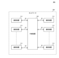
- FIG. 1 is a diagram showing the configuration of a communication system according to an embodiment of the present disclosure.
- FIG. 2 is a diagram illustrating a configuration of a relay device according to an embodiment of the present disclosure
- FIG. 3 is a diagram illustrating an example of distribution of target messages and reception times received by a relay device according to an embodiment of the present disclosure.
- FIG. 4 is a diagram illustrating an example of statistical values used for detection processing in the relay device according to the embodiment of the present disclosure.
- FIG. 5 is a diagram illustrating an example of distribution of target messages and reception times received by the relay device according to the embodiment of the present disclosure.
- FIG. 6 is a diagram illustrating an example of statistical values used for detection processing in a relay device according to a comparative example of the embodiment of the present disclosure;
- FIG. 1 is a diagram showing the configuration of a communication system according to an embodiment of the present disclosure.
- FIG. 2 is a diagram illustrating a configuration of a relay device according to an embodiment of the present disclosure
- FIG. 3 is
- FIG. 7 is a diagram illustrating an example of statistical values used for detection processing in the relay device according to the embodiment of the present disclosure.
- FIG. 8 is a diagram illustrating another example of distribution of target messages and reception times received by the relay device according to the embodiment of the present disclosure.
- FIG. 9 is a diagram illustrating an example of statistical values used for detection processing in the relay device according to the embodiment of the present disclosure.
- FIG. 10 is a diagram illustrating another example of distribution of target messages and reception times received by the relay device according to the embodiment of the present disclosure.
- FIG. 11 is a diagram illustrating an example of statistical values used for detection processing in the relay device according to the embodiment of the present disclosure.
- FIG. 12 is a flowchart that defines an example of an operation procedure when the relay device according to the embodiment of the present disclosure performs detection processing.
- FIG. 13 is a diagram illustrating an example of a network connection topology according to an embodiment of the present disclosure.
- 14 is a diagram illustrating an example of anomaly degrees calculated by a calculation unit in
- the present disclosure has been made to solve the above-mentioned problems, and its purpose is to provide a detection device and a detection method capable of more accurately detecting anomalies in networks.
- a detection device is a detection device for detecting an anomaly in a network in which a plurality of messages including periodic messages are transmitted and received, wherein observation results of the plurality of messages and the observation results a calculation unit that calculates a detection index that increases or decreases according to the relationship with reference information related to the and a reset unit that monitors a detection index and resets the detection index used in the detection process when an extreme value of the detection index is detected.
- the detection process is performed based on the detection index that increases or decreases according to the relationship between the observation result of the message and the reference information related to the observation result, and the detection index is reset when an extreme value of the detection index is detected.
- detection processing can be performed based on the reset detection index.
- the reference information may be a past reception interval of the message calculated based on the observation result, and the calculation unit is calculated based on the observation result.
- moving average value of the message reception intervals using the message reception intervals and the past message reception intervals, The moving average value that increases or decreases accordingly may be calculated for each message as the detection index.
- detection processing can be performed using a moving average value that is likely to change according to the occurrence of anomalies in the network, so occurrence of anomalies can be detected early.
- the detection unit may determine that an abnormality has occurred in the network when the detection index is less than a predetermined threshold value, and the reset unit may determine that an abnormality has occurred in the network.
- the detection index used in the detection process may be reset.
- the reference information may be an average value of reception intervals of the messages
- the calculation unit calculates the reception intervals of the messages calculated based on the observation result, Using the average value and the standard deviation of the message reception interval, the statistical value of the message reception interval, which increases or decreases according to the magnitude of the difference between the message reception interval and the average value A statistic may be calculated for each message as the detection indicator.
- the detection unit may determine that an abnormality has occurred in the network when the detection index is greater than a predetermined threshold value, and the reset unit may determine that an abnormality has occurred in the network.
- the detection index used in the detection process may be reset.
- a detection method is a detection method in a detection device for detecting anomalies in a network in which a plurality of messages including periodic messages are transmitted and received, wherein observation results of the plurality of messages and calculating a detection index that increases or decreases according to the relationship with the reference information related to the observation result; performing a detection process for detecting an anomaly in the network based on the calculated detection index; monitoring and resetting the sensing metric used in the sensing process if an extreme value of the sensing metric is detected.
- the detection process is performed based on the detection index that increases or decreases according to the relationship between the observation result of the message and the reference information related to the observation result, and the detection index is reset when an extreme value of the detection index is detected.
- detection processing can be performed based on the reset detection index.
- FIG. 1 is a diagram showing the configuration of a communication system according to an embodiment of the present disclosure.
- communication system 301 includes relay device 101 and a plurality of communication devices 111 .
- Communication system 301 is mounted on a vehicle, for example.
- communication device 111 is, for example, an in-vehicle ECU (Electronic Control Unit).
- the relay device 101 and the communication device 111 constitute a network 201. More specifically, relay device 101 and communication device 111 are connected to each other via transmission line 10 .
- the transmission line 10 is, for example, CAN (Controller Area Network) (registered trademark), FlexRay (registered trademark), MOST (Media Oriented Systems Transport) (registered trademark), Ethernet (registered trademark), and LIN (Local Interconnect Network). It is a cable that complies with the standards of
- the relay device 101 can communicate with the communication device 111.
- the relay device 101 performs relay processing for relaying information exchanged between a plurality of communication devices 111 connected to different transmission lines 10, for example.
- a plurality of messages including periodically transmitted messages are transmitted and received.
- periodic message is not limited to strictly periodic messages, but means messages of a type that should be periodically transmitted.
- messages that are irregularly transmitted from the communication device 111 to another communication device 111 via the relay device 101 in addition to the periodic messages are also referred to as event messages.
- Transmission of messages by the communication device 111 may be performed by broadcasting, unicasting, or multicasting.
- the relay device 101 functions as a detection device and detects an abnormality in the network 201. For example, relay device 101 detects the presence of an unauthorized message on network 201 as an anomaly in network 201 .
- FIG. 2 is a diagram illustrating a configuration of a relay device according to an embodiment of the present disclosure
- relay device 101 includes communication processing unit 11 , calculation unit 12 , reset unit 13 , detection unit 14 , storage unit 15 and multiple communication ports 16 .
- a part or all of the communication processing unit 11, the calculation unit 12, the reset unit 13, and the detection unit 14 are realized by, for example, a processing circuit (circuitry) including one or more processors.
- the storage unit 15 is, for example, a flash memory included in the processing circuit.
- Communication port 16 is, for example, a connector or terminal.
- a transmission line 10 is connected to each communication port 16 .
- the communication processing unit 11 performs relay processing for relaying messages transmitted between the communication devices 111 . For example, when the communication processing unit 11 receives a message from the communication device 111 via the corresponding transmission line 10 and the corresponding communication port 16, it generates a message CP that is a copy of the received message, and adds the received message CP to the generated message CP. Adds a timestamp indicating the time the message was received. Then, the communication processing unit 11 transmits the received message to the other communication device 111 via the corresponding communication port 16 and the corresponding transmission line 10 and outputs the time-stamped message CP to the calculation unit 12 .
- the calculation unit 12 calculates a detection index that increases or decreases according to the relationship between the reception time of the message and the reference information regarding the reception time.
- the reception time of the message is an example of the observation result of the message.
- the calculation unit 12 acquires the reception time t of the message to be detected by the relay device 101 among the messages relayed by the communication processing unit 11 .
- a message to be detected by the relay device 101 is also referred to as a target message.
- the target message may be one type of message transmitted from one communication device 111 or multiple types of messages transmitted from each of a plurality of communication devices 111 .
- An example in which the relay device 101 performs detection processing with a message transmitted from a communication device 111 as the "target message M" will be described below.
- the storage unit 15 stores an ID for each type of target message.
- the ID of the target message M will also be referred to as a target ID.
- the calculation unit 12 receives the message CP from the communication processing unit 11 and confirms the ID included in the received message CP and the target ID in the storage unit 15 .
- the calculation unit 12 recognizes that the copy source message of the message CP is the target message M, and By referring to the given time stamp, the reception time t of the target message M is obtained.
- the calculation unit 12 When the calculation unit 12 acquires the reception time t of the target message M, it calculates the difference between the reception time t and the reception time t of the previous target message M as the target message M reception interval x. More specifically, the calculator 12 calculates the (m ⁇ 1)-th target message M(m ⁇ 1), the reception interval xm of the target message Mm is calculated by subtracting the reception time t(m ⁇ 1). where m is a positive integer. The calculation unit 12 stores the calculated reception interval xm in the storage unit 15 .
- the calculation unit 12 calculates a detection index using the calculated reception interval x. For example, the calculation unit 12 calculates the statistical value T of the reception interval x for each target message M using the standard deviation ⁇ of the reception interval x. The statistical value T indicates the degree of deviation of the reception interval x from the normal state. Statistical value T is an example of a detection index.
- the calculator 12 calculates the anomaly degree Dm of the target message Mm according to the following equation (1).
- ⁇ is the average value of the reception interval x and is an example of reference information regarding the target message M.
- the standard deviation ⁇ and the average value ⁇ are stored in the storage unit 15 .
- the standard deviation ⁇ is calculated in advance by the manufacturer of the communication system 301 based on the reception interval x and stored in the storage unit 15 .
- the average value ⁇ is a value calculated in advance by the manufacturer of the communication system 301 based on the design value of the transmission cycle of the target message M in the network 201 and stored in the storage unit 15 in advance.
- the calculation unit 12 periodically or irregularly calculates the standard deviation ⁇ and the average ⁇ based on a plurality of reception intervals x corresponding to a plurality of target messages M, and calculates the standard deviation ⁇ and the average ⁇ in the storage unit 15.
- the value ⁇ may be updated to the calculated standard deviation ⁇ and mean ⁇ .
- the calculator 12 calculates the statistical value Tm of the target message Mm according to the following equation (2).
- the statistic value Tm of the target message Mm is a value obtained by subtracting the restriction parameter k from the sum of the statistic value T(m ⁇ 1) of the target message M(m ⁇ 1) and the degree of anomaly Dm. , and zero, whichever is greater.
- the statistical value Tm increases or decreases according to the magnitude of the difference between the reception interval xm of the target message Mm and the average value ⁇ . Specifically, when the reception interval xm becomes a value greatly deviating from the average value ⁇ and the abnormality degree Dm becomes a value larger than the limit parameter k, the statistic value Tm of the target message Mm is A value larger than the statistical value T(m-1) of the message M(m-1).
- the statistic value Tm of the target message Mm becomes zero, or The value is smaller than the statistical value T(m-1) of the target message M(m-1).
- the calculation unit 12 After calculating the statistical value Tm, the calculation unit 12 stores the calculated statistical value Tm in the storage unit 15 .
- the detection unit 14 performs detection processing for detecting an abnormality in the network 201 based on the statistical value T calculated by the calculation unit 12 . For example, the detection unit 14 detects the presence of an unauthorized message in the network 201 as an abnormality in the network 201 based on the statistical value T calculated by the calculation unit 12 and a predetermined threshold value Thx.
- the detection unit 14 acquires the statistical value T calculated by the calculation unit 12 from the storage unit 15, and compares the acquired statistical value T with the threshold value Thx. The detection unit 14 determines that an abnormality has not occurred in the network 201 when the statistical value T is equal to or less than the threshold Thx. On the other hand, the detection unit 14 determines that an abnormality has occurred in the network 201 when the statistical value T is greater than the threshold value Thx.
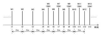
- FIG. 3 is a diagram showing an example of distribution of target messages and reception times received by the relay device according to the embodiment of the present disclosure.
- the horizontal axis indicates time.
- a plurality of target messages M received by communication processing unit 11 are legitimate periodic messages received at timings based on a predetermined transmission period Cm during a period from reception time t1 to reception time t12.
- target messages M1 to M4, M6, M8, M10, and M12, and target messages M5 and M7 which are fraudulent messages BM received, for example, at timings based on the transmission cycle Cm during the period from reception time t5 to reception time t13.
- M9, M11, M13 That is, during the period from reception time t5 to reception time t13, valid periodic messages and unauthorized periodic messages arrive alternately at relay apparatus 101.
- FIG. 4 is a diagram showing an example of statistical values used for detection processing in the relay device according to the embodiment of the present disclosure.
- the horizontal axis indicates time
- the vertical axis indicates statistical values.
- Statistical values T1 to T13 in FIG. 4 are statistical values T calculated by the calculation unit 12 according to the above-described equation (2) based on the reception times t1 to t13 of the target messages M1 to M13 shown in FIG.
- communication processing unit 11 receives only valid target messages M1 to M4 transmitted at fixed transmission cycle Cm, and reception intervals x1 to x4 are received. is approximately equal to the average value ⁇ , the statistical values T1 to T4 calculated by the calculator 12 are zero.
- the detection unit 14 determines that no abnormality has occurred in the network 201 during the period from the reception time t1 to the reception time t4. .
- the communication processing unit 11 receives the fraudulent message BM. Since x13 is a value that deviates from the average value ⁇ , the statistical values T5 to T13 calculated by the calculator 12 gradually increase.
- the detection unit 14 determines that an abnormality has occurred in the network 201 at reception time t9.
- the detection unit 14 transmits alarm information indicating that an abnormality has occurred in the network 201 to a higher-level device outside the communication system 301 via the communication processing unit 11 .
- a host device is, for example, a device such as a server that receives alarm information and performs predetermined processing.
- the threshold Thx can be arbitrarily set by the network 201 manufacturer. For example, by setting threshold Thx to a smaller value, it is possible to determine that an abnormality has occurred in network 201 earlier after transmission of an unauthorized message in network 201 has started.
- FIG. 5 is a diagram showing an example of distribution of target messages and reception times received by the relay device according to the embodiment of the present disclosure.
- the horizontal axis indicates time.
- FIG. 5 shows target messages M14 to M16 received by the communication processing unit 11 at reception times t14 to t16 after reception time t13 shown in FIG.
- the target messages M14 to M16 received by the communication processing unit 11 are legitimate periodic messages transmitted at the transmission period Cm during the period from reception time t14 to reception time t16. That is, at the reception time t13, the arrival of the unauthorized message to the relay device 101 has ended.
- FIG. 6 is a diagram illustrating an example of statistical values used for detection processing in a relay device according to a comparative example of the embodiment of the present disclosure;
- the horizontal axis indicates time, and the vertical axis indicates statistical values.
- Statistical values T4 to T16 in FIG. 6 are statistical values T calculated by the calculation unit 12 according to the above-described equation (2) based on the reception times t4 to t16 of the target messages M4 to M16 shown in FIG.
- the network 201 since the statistical values T14 to T16 are larger than the threshold value Thx, in addition to the period from the reception time t9 to the reception time t13, the network 201 It is determined that an abnormality has occurred in That is, when the relay device according to the comparative example performs the detection processing based on the statistical values T14 to T16, the arrival of the unauthorized message has ended at the reception time t13, and the network 201 has not been attacked. In spite of this, the end of arrival of the unauthorized message cannot be detected, and it is determined that the abnormality in the network 201 continues.
- the relay device 101 solves the above problem with the following configuration.
- the reset unit 13 monitors the statistical value T, and resets the statistical value T used in the detection process when the maximum value of the statistical value T is detected. For example, the reset unit 13 determines whether or not the statistical value T is the maximum value. If the reset unit 13 determines that the statistic value T at a certain timing is the maximum value and the statistic value T is greater than the threshold value Thx, the reset unit 13 resets the statistic value T at the timing for updating.
- the detecting unit 14 determines that the statistical value T is not the maximum value by the reset unit 13, or The detection process based on the statistical value T waits until the value T is updated.
- the detection unit 14 performs detection processing based on the statistical value T.
- the detection unit 14 performs detection processing based on the updated statistical value T.
- the detection unit 14 may sequentially perform detection processing based on the statistical value T each time the reset unit 13 determines that the statistical value T is not the maximum value or the statistical value T is updated. Alternatively, a predetermined number of statistical values T determined by the reset unit 13 to be not the maximum value or updated may be accumulated, and based on the accumulated statistical values T, detection processing may be performed ex post facto.
- FIG. 7 is a diagram showing an example of statistical values used for detection processing in the relay device according to the embodiment of the present disclosure.
- the horizontal axis indicates time
- the vertical axis indicates statistical values.
- Statistical values T4 to T13 in FIG. 7 are statistical values T calculated by the calculation unit 12 according to the above-described equation (2) based on the reception times t4 to t13 of the target messages M4 to M13 shown in FIG.
- Statistical values T14 to T16 in FIG. 7 are calculated by the calculating unit 12 according to the above equation (2) based on the receiving times t14 to t16 of the target messages M14 to M16, and the statistical values T updated by the resetting unit 13. is.
- reset unit 13 monitors statistical value T stored in storage unit 15 by calculating unit 12, and determines that two statistical values T, ie, statistical value T(m ⁇ 1) and statistical value Tm are consecutive. and the two statistical values T(m+1) and T(m+2) are continuously decreasing, it is determined that the statistical value Tm is the maximum value.
- the reset unit 13 refers to the storage unit 15, the statistical value T13 has increased from the statistical value T12, the statistical value T14 has increased from the statistical value T13, and the statistical value T15 has increased from the statistical value T14. and the statistical value T16 is reduced from the statistical value T15. Since the statistical values T13 and T14 are continuously increasing and the statistical values T15 and T16 are continuously decreasing, the reset unit 13 determines that the statistical value T14 is the maximum value.
- the reset unit 13 updates the statistical value T14 in the storage unit 15 to, for example, a reset value of zero. Further, the reset unit 13 updates the other statistical values T15 and T16 calculated after the calculation timing of the statistical value T14 and stored in the storage unit 15 based on the updated statistical value T14. More specifically, the reset unit 13 uses the updated statistical value T14 to calculate the statistical value T15 according to the above-described formula (2).
- the reset unit 13 After calculating the statistical value T15, the reset unit 13 updates the statistical value T15 in the storage unit 15 to the calculated statistical value T15.
- the reset unit 13 similarly calculates the statistical value T16, and updates the statistical value T16 in the storage unit 15 to the calculated statistical value T16.
- the detection unit 14 determines that no abnormality has occurred in the network 201 during the period from reception times t14 to t16 because the statistical values T14 to T16 after updating by the reset unit 13 are equal to or less than the threshold value Thx. That is, the detection unit 14 determines that the abnormal state that started at the reception time t9 ended by the reception time t13.
- the configuration in which the detection unit 14 performs the detection processing based on the reset statistical value T14 makes it possible for the relay apparatus 101 to perform fraudulent operations more effectively than the configuration in which the detection processing is performed based on the non-reset statistical value T14.
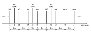
- FIG. 8 is a diagram showing another example of distribution of target messages and reception times received by the relay device according to the embodiment of the present disclosure.
- the horizontal axis indicates time.
- a plurality of target messages M received by communication processing unit 11 are legitimate periodic messages received at timings based on transmission period Cm during the period from reception time t1 to reception time t11.
- Target messages M1, M3, M4, M6, M7, M9 to M11, and unauthorized messages BM received at timings based on, for example, a cycle that is twice the transmission cycle Cm during the period from reception time t2 to reception time t8.
- FIG. 9 is a diagram showing an example of statistical values used for detection processing in the relay device according to the embodiment of the present disclosure.
- the horizontal axis indicates time, and the vertical axis indicates statistical values.
- Statistical values T1 to T8 in FIG. 9 are statistical values T calculated by the calculation unit 12 according to the above-described equation (2) based on the reception times t1 to t8 of the target messages M1 to M8 shown in FIG.
- Statistical values T9 to T11 in FIG. 9 are calculated by the calculating unit 12 according to the above equation (2) based on the reception times t9 to t11 of the target messages M9 to M11, and the statistical values T updated by the resetting unit 13. is.
- communication processing unit 11 receives unauthorized target message M2 at reception time t2 before transmission cycle Cm elapses from reception time t1 of legitimate target message M1, and transmission cycle Cm starts from reception time t1. Since the valid target message M3 is received by the communication processing unit 11 at the reception time t3 after Cm has elapsed, the statistical values T2 and T3 calculated by the calculation unit 12 gradually increase.
- the statistical value T4 calculated by the calculating unit 12 decreases from the statistical value T3.
- the communication processing unit 11 receives the unauthorized target message M5, and at reception time t6 after the transmission cycle Cm elapses from reception time t4, the valid message M5 is received.
- the target message M6 is received by the communication processing unit 11 . Therefore, the statistical values T5 and T6 calculated by the calculator 12 gradually increase, and the statistical values T5 and T6 exceed the threshold value Thx. Since the statistical value T5 calculated by the calculation unit 12 is larger than the threshold value Thx, the detection unit 14 determines that an abnormality has occurred in the network 201 at the reception time t5.
- the statistical value T7 calculated by the calculating unit 12 decreases from the statistical value T6. .
- an unauthorized target message M8 is received by the communication processing unit 11 at reception time t8 before the transmission cycle Cm has passed since reception time t7, and is valid at reception time t9 after transmission cycle Cm has passed since reception time t7. Since the target message M9 is received by the communication processing unit 11, the statistical values T8 and T9 calculated by the calculation unit 12 gradually increase.
- the valid target message M10 is received by the communication processing unit 11 at the reception time t10 after the transmission cycle Cm has passed since the reception time t9, and the valid target message M11 is received at the reception time t11 after the transmission cycle Cm has passed since the reception time t10. Since M11 is received by the communication processing unit 11, the statistical values T10 and T11 calculated by the calculating unit 12 gradually decrease from the statistical value T9.
- the reset unit 13 determines that the statistical value T9 is the maximum value because the statistical values T8 and T9 are continuously increasing and the statistical values T10 and T11 are continuously decreasing. Then, the reset unit 13 updates the statistical value T9 to the reset value because the statistical value T9 determined to be the maximum value is greater than the threshold value Thx. Furthermore, the reset unit 13 updates the statistical value T10 calculated by the calculating unit 12 to the statistical value T10 calculated using the updated statistical value T9, and updates the statistical value T11 calculated by the calculating unit 12. It is updated to the statistical value T11 calculated using the later statistical value T10.
- the detection unit 14 determines that no abnormality has occurred in the network 201 during the period from reception time t9 to t11. That is, the detection unit 14 determines that the abnormal state that started at the reception time t5 ended by the reception time t8.
- FIG. 10 is a diagram showing another example of distribution of target messages and reception times received by the relay device according to the embodiment of the present disclosure.
- the horizontal axis indicates time.
- a plurality of target messages M received by communication processing unit 11 are legitimate periodic messages received at timings based on transmission period Cm during the period from reception time t1 to reception time t12.
- FIG. 11 is a diagram showing an example of statistical values used for detection processing in the relay device according to the embodiment of the present disclosure.
- the horizontal axis indicates time, and the vertical axis indicates statistical values.
- Statistical values T1 to T9 in FIG. 11 are statistical values T calculated by the calculation unit 12 according to the above-described equation (2) based on the reception times t1 to t9 of the target messages M1 to M9 shown in FIG.
- Statistical values T10 to T12 in FIG. 11 are calculated by the calculating unit 12 according to the above equation (2) based on the reception times t10 to t12 of the target messages M10 to M12, and the statistical values T updated by the resetting unit 13. is.
- communication processing unit 11 receives unauthorized target message M2 at reception time t2 before transmission cycle Cm elapses from reception time t1 of legitimate target message M1, and transmission cycle starts from reception time t1. Since the valid target message M3 is received by the communication processing unit 11 at the reception time t3 after Cm has elapsed, the statistical values T2 and T3 calculated by the calculation unit 12 gradually increase.
- the statistical value T4 calculated by the calculating unit 12 decreases from the statistical value T3.
- the communication processing unit 11 receives the valid target message M5 and the illegal target message M6, which are transmitted irregularly, respectively, and The valid target message M7 is received by the communication processing unit 11 at the reception time t7 after the transmission period Cm has elapsed from the reception time t4. Therefore, the statistical values T5, T6, T7 calculated by the calculation unit 12 gradually increase, and the statistical values T6, T7 exceed the threshold value Thx. Since the statistical value T6 calculated by the calculation unit 12 is larger than the threshold value Thx, the detection unit 14 determines that an abnormality has occurred in the network 201 at the reception time t6.
- the statistical value T8 calculated by the calculating unit 12 decreases from the statistical value T7. .
- the communication processing unit 11 receives the unauthorized target message M9, and at reception time t10 after the transmission cycle Cm elapses from reception time t8, the valid message M9 is received. Since the target message M10 is received by the communication processing unit 11, the statistical values T9 and T10 calculated by the calculation unit 12 gradually increase.
- the valid target message M11 is received by the communication processing unit 11 at the reception time t11 after the transmission cycle Cm has passed since the reception time t10, and the valid target message M11 is received at the reception time t12 after the transmission cycle Cm has passed since the reception time t11. Since M12 is received by the communication processing unit 11, the statistical values T11 and T12 calculated by the calculating unit 12 gradually decrease from the statistical value T10.
- the reset unit 13 determines that the statistical value T10 is the maximum value. Then, the reset unit 13 updates the statistical value T10 to the reset value because the statistical value T10 determined to be the maximum value is greater than the threshold value Thx. Furthermore, the reset unit 13 updates the statistical value T11 calculated by the calculating unit 12 to the statistical value T11 calculated using the updated statistical value T10, and updates the statistical value T12 calculated by the calculating unit 12. The statistical value is updated to the statistical value T12 calculated using the later statistical value T11.
- the detection unit 14 determines that no abnormality has occurred in the network 201 during the period from reception times t10 to t12.
- the relay device 101 may be configured to perform detection processing based on a detection index other than the statistical value T.
- the calculation unit 12 calculates the detection index using a moving average of the receiving interval x of the target message M.
- the calculation unit 12 calculates, for each target message M, the moving average value A of the reception interval x of the latest p target messages M received by the communication processing unit 11 .
- p is an integer of 2 or more.
- the moving average value A is an example of a detection index.
- the calculation unit 12 calculates the reception interval xm of the target message Mm, the reception interval xm and the past target messages M(m ⁇ 1), M(m ⁇ 2) . . . M(m ⁇ p+1) receiving intervals x(m ⁇ 1), x(m ⁇ 2), .
- the reception intervals x(m ⁇ 1), x(m ⁇ 2), . . . , x(m ⁇ p+1) are also referred to as reference intervals rm.
- the moving average value Am increases or decreases according to the magnitude relationship between the reception interval xm of the target message Mm and the reference interval rm.
- the moving average value A calculated by the calculation unit 12 is gradually decreases during the period of
- the detection unit 14 performs detection processing based on the moving average value A calculated by the calculation unit 12 .
- the detection unit 14 detects an abnormality in the network 201 based on the moving average value A calculated by the calculation unit 12 and a predetermined threshold value Thy.
- the detection unit 14 compares the moving average value A calculated by the calculation unit 12 with the threshold value Thy. If the moving average value A is greater than or equal to the threshold value Thy, the detection unit 14 determines that an abnormality has not occurred in the network 201 . On the other hand, when the moving average value A is less than the threshold value Thy, the detection unit 14 determines that an abnormality has occurred in the network 201 .
- the reset unit 13 monitors the moving average value A, and resets the moving average value A used in the detection process when the minimum value of the moving average value A is detected. For example, the reset unit 13 determines whether the moving average value A is the minimum value in the same manner as the procedure for determining whether the statistical value T is the maximum value. The reset unit 13 updates the moving average value A by resetting it when determining that the moving average value A is a minimum value and when the moving average value A is less than the threshold value Thy.
- the detection unit 14 performs detection processing based on the updated moving average value A.
- FIG. 12 is a flowchart that defines an example of an operation procedure when the relay device according to the embodiment of the present disclosure performs detection processing.
- relay device 101 waits for arrival of a message (NO in step S102), and upon receiving a message (YES in step S102), determines whether or not the received message is target message M. It judges (step S104).
- the relay device 101 determines that the received message is not the target message M (NO in step S106), it waits for the arrival of a new message (NO in step S102).
- the relay device 101 determines that the received message is the target message M (YES in step S106)
- the statistic value T is calculated using the reception time t of the target message M.
- the relay device 101 stores the calculated statistical value T in the storage unit 15 (step S108).
- the relay device 101 determines whether or not the statistical value T calculated a predetermined number of times before is the maximum value (step S110).
- the relay apparatus 101 determines that the statistical value T calculated a predetermined number of times before is not the maximum value (NO in step S112), it performs detection processing based on the statistical value T (step S116).
- the relay apparatus 101 determines that the statistical value T calculated a predetermined number of times before is the maximum value (YES in step S112), the statistical value T is reset and updated. Also, the relay apparatus 101 updates another statistical value T calculated after the calculation timing of the statistical value T and stored in the storage unit 15 based on the updated statistical value T (step S114).
- the relay device 101 performs detection processing based on the updated statistical value T (step S116).
- relay device 101 determines that no abnormality has occurred in network 201 (NO in step S118)
- relay device 101 waits for the arrival of a new message (NO in step S102).
- relay device 101 determines that an abnormality has occurred in network 201 (YES in step S118)
- relay device 101 transmits alarm information indicating that an abnormality has occurred in network 201 to a host device outside communication system 301 (step S120).
- the relay device 101 waits for the arrival of a new message (NO in step S102).
- the configuration is not limited to this.
- a device other than the relay device 101 may function as a detection device and detect an abnormality in the network 201 .
- communication system 301 comprises a sensing device connected to relay device 101 via transmission line 10 .
- the relay device 101 Upon receiving a message from the communication device 111 , the relay device 101 transmits a mirror message, which is a copy of the received message, to the detection device via the transmission line 10 .
- the detection device calculates a detection index and performs detection processing based on the reception time in the relay device 101 of the mirror message received from the relay device 101 .
- the communication system 301 has a configuration in which the relay device 101 functioning as a detection device is directly connected to the transmission line 10, the configuration is not limited to this.
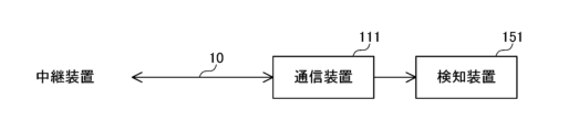
- FIG. 13 is a diagram showing an example of a network connection topology according to the embodiment of the present disclosure.
- detection device 151 may be configured to be connected to transmission line 10 via communication device 111 .
- the detection device 151 detects an abnormality in the network 201 by monitoring messages transmitted and received by the communication device 111, for example.
- detection device 151 includes calculation unit 12 , reset unit 13 , detection unit 14 and storage unit 15 .
- the calculation unit 12 in the detection device 151 acquires the reception time t of the target message M received by the communication device 111 and calculates the statistical value T based on the acquired reception time t.
- the calculation unit 12 is configured to calculate the statistic value T of the reception interval x, but the configuration is not limited to this.
- the calculation unit 12 is configured to periodically or irregularly calculate the communication load of the target message M, and calculate a detection index such as the statistical value T based on the communication load instead of the reception interval x.
- a communication load is an example of a message observation result.
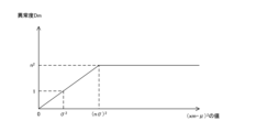
- the calculation unit 12 is configured to calculate the degree of abnormality Dm according to Equation (1), but the configuration is not limited to this. For example, when the reception interval xm satisfies the following expression (3), the calculation unit 12 calculates the abnormality degree Dm according to the expression (1), while when the reception interval xm satisfies the following expression (4), The degree of abnormality Dm is determined according to the formula (5).
- n is a preset constant based on the frequency distribution of legitimate periodic messages.
- FIG. 14 is a diagram showing an example of the degree of anomaly calculated by the calculator in the relay device according to the embodiment of the present disclosure.
- the horizontal axis indicates the square of the difference between the reception interval xm and the average value ⁇
- the vertical axis indicates the degree of abnormality Dm.
- the target message which is a legitimate event message received by communication processing unit 11
- the anomaly degree Dm of the target message Mm is a value equal to or less than the square of n. It is possible to suppress a large increase in T and suppress the occurrence of erroneous detection of abnormality in the normal state where the abnormal state has been resolved.
- the reset unit 13 continuously increases the two statistical values T, ie, the statistical value T(m ⁇ 1) and the statistical value Tm, and the statistical value
- the reset unit 13 resets a number of statistical values T from the statistical value T(m ⁇ a+1) to the statistical value Tm that are continuously increasing, and from the statistical value T(m+1) to the statistical value T(m+b):
- a configuration may be adopted in which, when the b statistical values T are continuously decreasing, the statistical value Tm is determined to be the maximum value.
- a and b are integers of 2 or more.
- the calculation unit 12 calculates a detection index that increases or decreases according to the relationship between the observation result of the target message M and the reference information related to the observation result. .
- the detection unit 14 performs detection processing for detecting an abnormality in the network 201 based on the detection index calculated by the calculation unit 12 .
- the reset unit 13 monitors the detection index, and resets the detection index used in the detection process when an extreme value of the detection index is detected.
- an extreme value means a maximum value or a minimum value.
- the detection process is performed based on the detection index that increases or decreases according to the relationship between the observation result of the message and the reference information related to the observation result, and the detection index is reset when an extreme value of the detection index is detected.
- detection processing can be performed based on the reset detection index.
- Each process (each function) of the above-described embodiment is realized by a processing circuit (circuitry) including one or more processors.
- the processing circuit may be configured by an integrated circuit or the like in which one or more memories, various analog circuits, and various digital circuits are combined in addition to the one or more processors.
- the one or more memories store programs (instructions) that cause the one or more processors to execute the processes.
- the one or more processors may execute the above processes according to the program read from the one or more memories, or execute the above processes according to a logic circuit designed in advance to execute the above processes. may be executed.
- the above processors are CPU (Central Processing Unit), GPU (Graphics Processing Unit), DSP (Digital Signal Processor), FPGA (Field Programmable Gate Array), and ASIC (Application Specific Integrate d Circuit), etc., which are suitable for computer control processor.
- the plurality of physically separated processors may cooperate with each other to execute the above processes.
- the processors installed in each of a plurality of physically separated computers cooperate with each other via networks such as LAN (Local Area Network), WAN (Wide Area Network), and the Internet to perform each of the above processes. may be executed.
- the program may be installed in the memory from an external server device or the like via the network, and may be CD-ROM (Compact Disc Read Only Memory), DVD-ROM (Digital Versatile Disk Read Only Memory), and semiconductor It may be distributed in a state stored in a recording medium such as a memory, and installed in the memory from the recording medium.
- CD-ROM Compact Disc Read Only Memory
- DVD-ROM Digital Versatile Disk Read Only Memory
- semiconductor It may be distributed in a state stored in a recording medium such as a memory, and installed in the memory from the recording medium.
Landscapes
- Engineering & Computer Science (AREA)
- Computer Networks & Wireless Communication (AREA)
- Signal Processing (AREA)
- Environmental & Geological Engineering (AREA)
- Health & Medical Sciences (AREA)
- Cardiology (AREA)
- General Health & Medical Sciences (AREA)
- Data Exchanges In Wide-Area Networks (AREA)
- Maintenance And Management Of Digital Transmission (AREA)
- Debugging And Monitoring (AREA)
Priority Applications (3)
| Application Number | Priority Date | Filing Date | Title |
|---|---|---|---|
| JP2023570798A JPWO2023127460A1 (https=) | 2021-12-28 | 2022-12-09 | |
| US18/718,856 US20250047585A1 (en) | 2021-12-28 | 2022-12-09 | Detection device and detection method |
| CN202280078383.7A CN118302994A (zh) | 2021-12-28 | 2022-12-09 | 检测装置和检测方法 |
Applications Claiming Priority (2)
| Application Number | Priority Date | Filing Date | Title |
|---|---|---|---|
| JP2021214171 | 2021-12-28 | ||
| JP2021-214171 | 2021-12-28 |
Publications (1)
| Publication Number | Publication Date |
|---|---|
| WO2023127460A1 true WO2023127460A1 (ja) | 2023-07-06 |
Family
ID=86998674
Family Applications (1)
| Application Number | Title | Priority Date | Filing Date |
|---|---|---|---|
| PCT/JP2022/045396 Ceased WO2023127460A1 (ja) | 2021-12-28 | 2022-12-09 | 検知装置および検知方法 |
Country Status (4)
| Country | Link |
|---|---|
| US (1) | US20250047585A1 (https=) |
| JP (1) | JPWO2023127460A1 (https=) |
| CN (1) | CN118302994A (https=) |
| WO (1) | WO2023127460A1 (https=) |
Citations (3)
| Publication number | Priority date | Publication date | Assignee | Title |
|---|---|---|---|---|
| JP2014146868A (ja) * | 2013-01-28 | 2014-08-14 | Hitachi Automotive Systems Ltd | ネットワーク装置およびデータ送受信システム |
| JP2019029961A (ja) * | 2017-08-03 | 2019-02-21 | 住友電気工業株式会社 | 検知装置、検知方法および検知プログラム |
| WO2021111685A1 (ja) * | 2019-12-05 | 2021-06-10 | 住友電気工業株式会社 | 検知装置、車両、検知方法および検知プログラム |
Family Cites Families (8)
| Publication number | Priority date | Publication date | Assignee | Title |
|---|---|---|---|---|
| JP5138293B2 (ja) * | 2007-07-05 | 2013-02-06 | 富士通株式会社 | 受信ダイバーシチを制御する通信装置および方法 |
| WO2014155495A1 (ja) * | 2013-03-25 | 2014-10-02 | Nttエレクトロニクス株式会社 | 通信装置、受信装置、及び送信装置 |
| JP6330277B2 (ja) * | 2013-09-10 | 2018-05-30 | 日本電気株式会社 | 送信装置、送信方法、送信プログラム、及び、中継システム |
| WO2018135604A1 (ja) * | 2017-01-19 | 2018-07-26 | 日本電気株式会社 | 抽出装置、抽出方法と記憶媒体、ならびに、異常検知装置、異常検知方法 |
| JP2019080119A (ja) * | 2017-10-20 | 2019-05-23 | 国立大学法人名古屋大学 | 車載通信装置、車載通信システム及び車載通信方法 |
| WO2020079874A1 (ja) * | 2018-10-18 | 2020-04-23 | 住友電気工業株式会社 | 検知装置、ゲートウェイ装置、検知方法および検知プログラム |
| WO2021152918A1 (ja) * | 2020-01-31 | 2021-08-05 | 住友電気工業株式会社 | 検知システム、検知装置および検知方法 |
| US12488101B2 (en) * | 2021-01-14 | 2025-12-02 | Autonetworks Technologies, Ltd. | Detection device, detection method and detection program |
-
2022
- 2022-12-09 JP JP2023570798A patent/JPWO2023127460A1/ja active Pending
- 2022-12-09 WO PCT/JP2022/045396 patent/WO2023127460A1/ja not_active Ceased
- 2022-12-09 CN CN202280078383.7A patent/CN118302994A/zh active Pending
- 2022-12-09 US US18/718,856 patent/US20250047585A1/en active Pending
Patent Citations (3)
| Publication number | Priority date | Publication date | Assignee | Title |
|---|---|---|---|---|
| JP2014146868A (ja) * | 2013-01-28 | 2014-08-14 | Hitachi Automotive Systems Ltd | ネットワーク装置およびデータ送受信システム |
| JP2019029961A (ja) * | 2017-08-03 | 2019-02-21 | 住友電気工業株式会社 | 検知装置、検知方法および検知プログラム |
| WO2021111685A1 (ja) * | 2019-12-05 | 2021-06-10 | 住友電気工業株式会社 | 検知装置、車両、検知方法および検知プログラム |
Also Published As
| Publication number | Publication date |
|---|---|
| US20250047585A1 (en) | 2025-02-06 |
| CN118302994A (zh) | 2024-07-05 |
| JPWO2023127460A1 (https=) | 2023-07-06 |
Similar Documents
| Publication | Publication Date | Title |
|---|---|---|
| US9380070B1 (en) | Intrusion detection mechanism | |
| EP3361677B1 (en) | Communication device, communication method and non-transitory storage medium | |
| US20210226872A1 (en) | Abnormality detection method, abnormality detection apparatus, and abnormality detection system | |
| JP6828632B2 (ja) | 検知装置、検知方法および検知プログラム | |
| TW201800972A (zh) | 侵入偵知裝置以及侵入偵知程式產品 | |
| JP2019174426A (ja) | 異常検知装置、異常検知方法およびプログラム | |
| US11316770B2 (en) | Abnormality detection apparatus, abnormality detection method, and abnormality detection program | |
| CN110289992B (zh) | 一种报文处理方法及装置 | |
| WO2023127460A1 (ja) | 検知装置および検知方法 | |
| CN110012490A (zh) | 告警方法、装置、操作维护中心及计算机可读存储介质 | |
| EP2566078B1 (en) | Determining a quality of a clock signal | |
| JP7175858B2 (ja) | 情報処理装置および正規通信判定方法 | |
| JP6528239B2 (ja) | 通信装置およびプログラム | |
| JP2019102011A (ja) | 学習装置、学習方法及び学習プログラム | |
| CN118592018A (zh) | 检测装置及检测方法 | |
| JP2005203992A (ja) | ネットワーク異常検出装置、ネットワーク異常検出方法およびネットワーク異常検出プログラム | |
| JP7694824B2 (ja) | 監視装置、車両監視方法および車両監視プログラム | |
| CN113542012B (zh) | 一种故障检测方法、故障检测装置及电子设备 | |
| CN111510443B (zh) | 基于设备画像的终端监测方法和终端监测装置 | |
| WO2022195887A1 (ja) | トラフィックセンサ、分析方法、および、分析プログラム | |
| CN118104217A (zh) | 检测装置、检测方法和检测程序 | |
| CN115664788B (zh) | 一种通信数据劫持监控方法及存储介质、电子设备 | |
| US20240214124A1 (en) | Abnormal frame determination device, abnormal frame determination method, and non-transitory computer readable medium | |
| CN117640281A (zh) | 装置和方法 | |
| WO2023233711A1 (ja) | 情報処理方法、異常判定方法、および、情報処理装置 |
Legal Events
| Date | Code | Title | Description |
|---|---|---|---|
| 121 | Ep: the epo has been informed by wipo that ep was designated in this application |
Ref document number: 22915684 Country of ref document: EP Kind code of ref document: A1 |
|
| ENP | Entry into the national phase |
Ref document number: 2023570798 Country of ref document: JP Kind code of ref document: A |
|
| WWE | Wipo information: entry into national phase |
Ref document number: 202280078383.7 Country of ref document: CN |
|
| WWE | Wipo information: entry into national phase |
Ref document number: 18718856 Country of ref document: US |
|
| NENP | Non-entry into the national phase |
Ref country code: DE |
|
| 122 | Ep: pct application non-entry in european phase |
Ref document number: 22915684 Country of ref document: EP Kind code of ref document: A1 |