WO2023120725A1 - Robotic hand, robot and robot controlling system - Google Patents
Robotic hand, robot and robot controlling system Download PDFInfo
- Publication number
- WO2023120725A1 WO2023120725A1 PCT/JP2022/047748 JP2022047748W WO2023120725A1 WO 2023120725 A1 WO2023120725 A1 WO 2023120725A1 JP 2022047748 W JP2022047748 W JP 2022047748W WO 2023120725 A1 WO2023120725 A1 WO 2023120725A1
- Authority
- WO
- WIPO (PCT)
- Prior art keywords
- elastic member
- robot hand
- finger
- modulus
- young
- Prior art date
Links
Images


Classifications
-
- B—PERFORMING OPERATIONS; TRANSPORTING
- B25—HAND TOOLS; PORTABLE POWER-DRIVEN TOOLS; MANIPULATORS
- B25J—MANIPULATORS; CHAMBERS PROVIDED WITH MANIPULATION DEVICES
- B25J15/00—Gripping heads and other end effectors
- B25J15/08—Gripping heads and other end effectors having finger members
-
- B—PERFORMING OPERATIONS; TRANSPORTING
- B25—HAND TOOLS; PORTABLE POWER-DRIVEN TOOLS; MANIPULATORS
- B25J—MANIPULATORS; CHAMBERS PROVIDED WITH MANIPULATION DEVICES
- B25J15/00—Gripping heads and other end effectors
- B25J15/08—Gripping heads and other end effectors having finger members
- B25J15/10—Gripping heads and other end effectors having finger members with three or more finger members
Definitions
- This disclosure relates to robot hands.
- Patent Document 1 Conventionally, there has been known a gripping control method that can lift an object with unknown weight and coefficient of friction by a robot hand or a manipulator without shifting the gripping position (see Patent Document 1, for example).
- a robot hand includes a plurality of fingers that grip an object to be gripped.
- the plurality of finger portions have a plurality of finger bodies and a plurality of elastic members arranged on the plurality of finger bodies.
- the plurality of elastic members have portions in which Young's modulus in a first direction in which a gripping force acts on the gripped object is lower than Young's modulus in a second direction intersecting with the first direction.
- a robot according to an embodiment of the present disclosure includes the robot hand and an arm connected to the robot hand.
- a robot control system includes the robot and a control device that controls the robot.
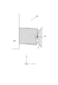
- FIG. 1 is a cross-sectional view showing a configuration example of a robot hand according to an embodiment
- FIG. FIG. 2 is an enlarged view of a portion surrounded by a dashed line in FIG. 1, showing an example of a state of an elastic member when an object to be gripped is gripped
- FIG. 4 is a cross-sectional view showing a configuration example in which the movement of an elastic member is restricted by a supporting portion
- FIG. 5 is a cross-sectional view showing an elastic member of a robot hand according to a comparative example
- FIG. 3 is a schematic diagram showing a configuration example of a robot hand including gripping fingers and regulating fingers
- FIG. 4 is a plan view showing a configuration example of a robot hand having gripping fingers and regulating fingers
- FIG. 4 is a cross-sectional view showing another configuration example of an elastic member
- FIG. 8 is a cross-sectional view taken along line AA of FIG. 7
- FIG. 8 is a cross-sectional view showing a configuration example when gripping an object to be gripped by the elastic member of FIG. 7
- FIG. 4 is a cross-sectional view showing a configuration example of an elastic member in which the first elastic member and the second elastic member are not laminated in the first direction and the first elastic member is positioned inside
- FIG. 4 is a cross-sectional view showing a configuration example of an elastic member in which the first elastic member and the second elastic member are not laminated in the first direction and the first elastic member is positioned outside
- FIG. 4 is a cross-sectional view showing another configuration example of an elastic member
- FIG. 8 is a cross-sectional view taken along line AA of FIG. 7
- FIG. 8 is a cross-sectional view showing a configuration example when gripping an object to be gripped by the elastic member of FIG. 7
- FIG. 10 is a cross-sectional view showing another configuration example of the robot hand
- FIG. 4 is a cross-sectional view showing a configuration example of a robot hand provided with sensors
- FIG. 4 is a schematic diagram showing a configuration example of a robot hand including finger portions having elastic members and finger portions not having elastic members
- 1 is a schematic diagram showing a configuration example of a robot control system according to an embodiment
- a robot hand 10 (Configuration example of robot hand 10) is installed on a robot 2 (see FIG. 15).
- the robot hand 10 has fingers that grip a gripping object 8 (see FIG. 1, etc.).
- the robot hand 10 may have two fingers 20, for example, as shown in FIG.
- the two fingers 20 are configured to grip the gripping object 8 .
- At least one finger 20 comprises a first elastic member 21 , a second elastic member 22 and a finger body 24 .
- the Young's modulus of the first elastic member 21 may be lower than the Young's modulus of the second elastic member 22 .
- the first elastic member 21 and the second elastic member 22 are also collectively referred to as an elastic member.
- a gripping force acts in the direction normal to the surface where the fingers 20 contact the gripped object 8 .
- the direction in which the gripping force acts is also referred to as the first direction. In FIG. 1, the first direction corresponds to the X-axis direction.
- the finger body 24 includes a support portion 23 that supports the elastic member.
- the support portion 23 supports the elastic member so as to restrict movement of the elastic member in a direction intersecting the first direction.
- a direction that intersects the first direction is also referred to as a second direction.
- the first direction corresponds to the X-axis direction
- the second direction corresponds to a direction including a Y-axis direction or Z-axis direction component.
- the support portion 23 is configured to restrict the movement of the elastic member in contact with the grasped object 8 in the second direction when the finger portion 20 grasps the grasped object 8 .
- the support portion 23 is configured as an inner wall of a concave portion provided in the finger body 24 .
- the inner wall of the recess of the finger body 24 functions as the support portion 23 by accommodating the elastic member in the recess provided in the finger body 24 .
- the plurality of elastic members are arranged in the plurality of concave portions of the finger body 24 respectively.
- FIG. 2 shows an example of the state of the elastic member when the gripping object 8 is gripped.
- FIG. 2 corresponds to an enlarged view of the portion enclosed by the dashed line in FIG.
- a position at which the elastic member and the grasped object 8 contact when the grasped object 8 is grasped by the finger portion 20 is referred to as a contact point 8P.
- a gripping force FX in the X-axis direction acts on the elastic member from the contact point 8P.
- the elastic member is compressed by the gripping force FX.
- the Young's modulus of the first elastic member 21 in the X-axis direction is lower than the Young's modulus of the second elastic member 22 in the X-axis direction.
- the first elastic member 21 is compressed more in the X-axis direction than the second elastic member 22 . It is assumed that the deformation of the second elastic member 22 in the X-axis direction is negligibly small.
- the inner surface of the first elastic member 21 (the surface facing the gripped object 8) when the gripping force FX is acting is represented by a solid line 21A.
- the inner surface of the first elastic member 21 in the state where the gripping force FX is not acting is represented by a chain double-dashed line 21B.
- the thickness of the first elastic member 21 in the X-axis direction when the gripping force FX is acting is represented by XA.
- XB represents the thickness of the first elastic member 21 in the X-axis direction when the gripping force FX is not applied.
- the amount of compression of the first elastic member 21 by the gripping force FX is expressed as XB-XA.
- the Young's modulus of the elastic member as a whole is low in the X-axis direction. Since the elastic member has a low Young's modulus in the X-axis direction, even if the fingers 20 are moved in the X-axis direction to grip the gripping object 8, the gripping force applied to the gripping object 8 is reduced. Small in size. In other words, the change rate of the gripping force with respect to the movement of the fingers 20 is small. Since the rate of change in gripping force with respect to movement of the fingers 20 is small, the gripping force applied from the fingers 20 to the gripped object 8 can be easily controlled. As a result, an excessive grasping force that damages the grasped object 8 is less likely to be applied.
- a frictional force is generated between the gripping object 8 and the elastic member by the gripping force FX.
- a A static friction force is generated to balance the inertia force FZ (such as the inertia force due to gravity or the acceleration of the robot 2).
- the inertial force FZ acts in a direction intersecting the direction in which the gripping force FX acts (gripping direction) at the contact point 8P between the gripped object 8 and the elastic member.
- the inertial force FZ in the negative direction of the Z-axis acts on the contact point 8P of the elastic member that is in contact with the grasped object 8, as illustrated in FIG.
- the contact point 8P in contact moves in the negative direction of the Z-axis.
- the inertial force FZ acts as a shear force on the second elastic member 22 .
- the second elastic member 22 is supported at a support point 22D by a support portion 23 positioned in the negative direction of the Z-axis, and supported at a support point 22U by a support portion 23 positioned in the positive direction of the Z-axis.
- the support portion 23 supports at least part of the elastic member so as to restrict the movement of the grasped object 8 in the second direction.
- the shear force acts to bend the second elastic member 22 in the negative direction of the Z-axis with the support point 22D as a fulcrum. It is assumed that the bending rigidity in the negative direction of the Z-axis at the support point 22D of the second elastic member 22 is sufficiently high such that the amount of bending due to the shear force can be ignored.
- the bending stiffness in the negative direction of the Z-axis at the support point 22D of the second elastic member 22 is the Young's modulus in the Z-axis direction of the second elastic member 22 and the second elastic modulus in the cross section including the support point 22D along the Z-axis direction. It is calculated as the product of the second moment of area of the member 22 in the Z-axis direction.
- the surface of the second elastic member 22 in contact with the grasped object 8 tilts in the Z-axis direction.
- the contact surface between the second elastic member 22 and the grasped object 8 is tilted in the Z-axis direction, thereby reducing the static friction force.
- the grasped object 8 becomes easier to slip. Therefore, since the second elastic member 22 is less likely to bend in the Z-axis direction at the support point 22D, the grasped object 8 is less likely to slip.
- the angle at which the second elastic member 22 is inclined with respect to the gripping direction is less than the predetermined angle, the static friction force is less likely to decrease.
- the predetermined angle can be determined based on the properties of the grasped object 8 .
- the characteristics of the grasped object 8 are, for example, the mass of the grasped object 8, the coefficient of static or dynamic friction between the grasped object 8 and the second elastic member 22, or the degree of grasping that does not damage the grasped object 8. May include force and the like.
- the angle at which the second elastic member 22 is inclined with respect to the gripping direction is such that the gap between the concave portion of the finger body 24 functioning as the support portion 23 and the second elastic member 22 crosses the edge of the support portion 23 (the concave portion of the finger body 24). It can be made small by being set so as to restrict the rotation of the second elastic member 22 as the rotation axis.
- a finger portion 920 according to the comparative example includes an elastic member 921 and a finger body 924 .
- the elastic member 921 tends to bend in the Z-axis direction, although excessive gripping force is less likely to be applied to the gripped object 8 .
- the elastic member 921 illustrated in FIG. 4 is bent in the Z-axis direction compared to the original shape (the shape when the gripping object 8 is not gripped) indicated by the two-dot chain line. Then, the elastic member 921 bends in the Z-axis direction, so that the object to be grasped 8 slides easily.
- the elastic member 921 has a high Young's modulus
- the elastic member 921 is less likely to bend in the Z-axis direction, making it difficult for the grasped object 8 to slip, but an excessive grasping force is likely to be applied to the grasped object 8 .
- the gripping object 8 can be damaged by applying excessive gripping force to the gripping object 8 .
- the Young's modulus in the gripping direction is low for the elastic member as a whole. Moreover, the bending rigidity in the direction intersecting with the gripping direction is high. By doing so, an excessive gripping force is less likely to be applied to the gripping object 8 . In addition, the grasped object 8 is less likely to slip. As a result, gripping stability is improved.
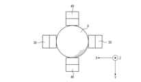
- the robot hand 10 may include gripping fingers 30 and regulating fingers 40, as shown in FIGS.
- the gripping fingers 30 are configured to grip the gripping object 8 in the X-axis direction (first direction).
- the restricting fingers 40 are configured to restrict the elastic members of the gripping fingers 30 contacting the gripping object 8 from moving in the Z-axis direction (second direction).
- the regulating fingers 40 assist in gripping the gripping object 8 when the gripping fingers 30 grip the gripping object 8, and reduce the force acting on the elastic member of the gripping fingers 30 in the second direction. It is configured to indirectly restrict the movement of the elastic members of the gripping fingers 30 in the Z-axis direction (second direction).
- the Young's modulus and bending rigidity of the portion of the regulating finger 40 contacting the grasped object 8 are higher than the Young's modulus and bending rigidity of the portion of the grasping finger 30 contacting the grasped object 8 .
- the plurality of elastic members are arranged on at least one of the plurality of finger bodies 24, the first elastic member 21, and at least one other of the plurality of finger bodies 24.
- a second elastic member 22 having a Young's modulus higher than that of the member 21 may be provided.
- At least one finger body 24 on which the first elastic member 21 is arranged corresponds to the gripping finger 30 .
- At least one other finger body 24 on which the second elastic member 22 is arranged corresponds to the regulating finger 40 .
- the robot hand 10 includes a plurality of fingers 20 that grip the gripping target 8 .
- the plurality of finger portions 20 has a plurality of finger bodies 24 and a plurality of elastic members arranged on the plurality of finger bodies 24 .
- the plurality of elastic members are configured to have a portion in which the Young's modulus in the first direction in which the gripping force acts on the gripping object 8 is lower than the Young's modulus in the second direction intersecting the first direction. be done.
- the robot hand 10 is configured to restrict the movement of the elastic member in the second direction when gripping the gripping target 8 . By doing so, an excessive gripping force is less likely to act on the gripped object 8 and the gripped object 8 is less likely to slip. As a result, the stability of gripping by the robot hand 10 is improved.
- the elastic member illustrated in FIG. 2 is also called a laminated elastic member when it has a configuration in which the first elastic member 21 and the second elastic member 22 are laminated.
- the support portion 23 supports a portion of the laminated elastic member.
- the laminated elastic member has a first region and a second region in a portion of the laminated elastic member that is supported by the support portion 23 .
- the bending rigidity in the direction along the second direction in the second region is greater than the bending rigidity in the direction along the second direction in the first region.
- the second area is positioned closer to the grasped object 8 than the first area.
- the first region and the second region may correspond to the first elastic member 21 and the second elastic member 22, respectively.
- the first region and the second region may each correspond to two regions included in the second elastic member 22 .
- the first region and the second region may each correspond to two regions separated at any position in the elastic member.
- the laminated elastic member may have a long side component along the second direction at least in the cross section along the second direction in the second region. Also, the shape of the second elastic member 22 included in the laminated elastic member may be layered. The gap between the concave portion of the finger body 24 functioning as the support portion 23 and the second elastic member 22 is designed to restrict the rotation of the second elastic member 22 around the edge of the support portion 23 (the concave portion of the finger body 24) as the rotation axis. may be set to
- the elastic member may be configured as a single member instead of a member in which the first elastic member 21 and the second elastic member 22 are combined.
- the elastic member configured as a single member may be configured such that the Young's modulus in the first direction is less than the Young's modulus in the second direction.
- the first elastic member 21 and the second elastic member 22 do not have to be joined.
- the elastic member illustrated in FIG. 2 is configured such that a first elastic member 21 and a second elastic member 22 are laminated. Other configuration examples are described below.
- the second elastic member 22 includes a main body portion 22B and a protruding portion 22A arranged on the side of the plurality of finger main bodies 24 of the main body portion 22B and having a smaller width than the main body portion 22B. may have The projecting portion 22A of the second elastic member 22 is surrounded by the first elastic member 21 around the axis in the first direction. In other words, both the first elastic member 21 and the second elastic member 22 may be included in a predetermined cross section that intersects or is perpendicular to the gripping direction.
- the apparent Young's modulus in the first direction in an arbitrary cross section intersecting the first direction of the elastic member is the ratio of the area of the first elastic member 21 to the area of the second elastic member 22 in that cross section, and the first elastic member 21 and the Young's modulus of the second elastic member 22 in the first direction.
- the bending rigidity in the second direction at any position of the elastic member is determined based on the geometrical moment of inertia of each of the first elastic member 21 and the second elastic member 22 in the cross section including the bending direction.
- the flexural rigidity in the second direction can be enhanced by including the second elastic member 22 in the cross section.
- a gripping force FX acts on the second elastic member 22 from the gripping object 8 .
- a frictional force is generated between the gripping object 8 and the elastic member by the gripping force FX.
- a A static friction force is generated to balance the inertia force FZ (such as the inertia force due to gravity or the acceleration of the robot 2).
- the inertial force FZ acts in a direction intersecting the direction in which the gripping force FX acts (gripping direction).
- the inner surface of the first elastic member 21 (the surface facing the gripped object 8) when the gripping force FX is acting is represented by a solid line 21A.
- the inner surface of the first elastic member 21 in the state where the gripping force FX is not acting is represented by a chain double-dashed line 21B.
- the apparent Young's modulus in the first direction is lowered due to the narrow cross-sectional area of the projecting portion 22A of the second elastic member 22 .
- the projecting portion 22A of the second elastic member 22 can deform in the first direction together with the first elastic member 21 .
- the elastic members of the finger portion 20 include a first elastic member 21 extending in the first direction (the X-axis direction) in a rod shape, and an outer side of the first elastic member 21 formed in a cylindrical shape. It may be configured in combination with the surrounding second elastic member 22 . That is, the first elastic member 21 and the second elastic member 21 may be configured so as not to be stacked in the first direction.
- a member in which the first elastic member 21 and the second elastic member 21 are combined so as not to be laminated in the first direction is also called a composite elastic member.
- the composite elastic member may be configured such that the first elastic member 21 is positioned inside the second elastic member 22 .
- the plurality of elastic members include the columnar first elastic member 21 extending in the first direction, the Young's modulus of the first elastic member 21 higher than that of the first elastic member 21 and adjacent to the first elastic member 21, and the first elastic member 21 being adjacent to the first elastic member 21. It may be configured as a composite elastic member having a columnar second elastic member 22 extending in the direction. Also, the second elastic member 22 may be cylindrical. The first elastic member 21 may be positioned inside the second elastic member 22 .
- the second elastic member 22 may be configured to surround the entire circumference of the first elastic member 21 in a cross-sectional view that intersects the first direction (cross-sectional view including the second direction).
- the second elastic members 22 may be configured to be discretely positioned around the first elastic member 21 in a cross-sectional view that intersects the first direction.
- the second elastic member 22 may be positioned so as to restrict movement of the first elastic member 21 in at least one direction (for example, the negative direction of the Z-axis where gravity acts).
- the second elastic member 22 may be arranged at each position (position every 120 degrees) obtained by dividing the circumference of the first elastic member 21 into three equal parts, for example, in a cross-sectional view that intersects with the first direction.
- the second elastic member 22 may be arranged at four or more positions (at intervals of 90 degrees or less) obtained by equally dividing the periphery of the first elastic member 21 in a cross-sectional view that intersects the first direction.
- the position of the second elastic member 22 in a cross-sectional view that intersects the first direction does not have to be a position evenly divided around the first elastic member 21 .
- the second elastic member 22 may be arranged at any position around the first elastic member 21 in a cross-sectional view that intersects the first direction.
- the second elastic member 22 may be configured in a plate shape, rod shape, or the like extending in the first direction.
- the second elastic member 22 may be configured in various shapes without being limited to these examples.
- the first elastic member 21 first contacts the gripping object 8 , so that the contact point 8P between the elastic member and the gripping object 8 touches the first elastic member 21 .
- the second elastic member 22 does not contact the grasped object 8 .
- the apparent Young's modulus of the elastic member in the first direction when gripping the gripping object 8 is determined based on the Young's modulus of the first elastic member 21 .
- the bending rigidity in the second direction at any position of the elastic member is determined based on the geometrical moment of inertia of each of the first elastic member 21 and the second elastic member 22 in the cross section including the bending direction.
- the first elastic member 21 may protrude more than the second elastic member 22 on the side that contacts the grasped object 8 . By doing so, when the fingers 20 grip the gripped object 8, the gripped object 8 tends to come into contact with the first elastic member 21 first. As a result, excessive gripping force is less likely to be applied to the gripping object 8 .
- the elastic members of the finger portion 20 include a second elastic member 22 extending in a rod shape along the first direction (X-axis direction), and a cylindrical outer side of the second elastic member 22. It may be configured in combination with the surrounding first elastic member 21 .
- the first elastic member 21 and the second elastic member 22 are switched between the inside and the outside. That is, the composite elastic member may be configured such that the first elastic member 21 is positioned outside the second elastic member 22 .
- the first elastic member 21 may be cylindrical.
- the second elastic member 22 may be positioned inside the first elastic member 21 .
- the first elastic member 21 may protrude more than the second elastic member 22 on the side that contacts the grasped object 8 .
- the end portion of the first elastic member 21 may protrude to the side contacting the grasped object 8 more than the end portion of the second elastic member 22 .
- the apparent Young's modulus of the elastic member in the first direction when gripping the gripping object 8 is based on the Young's modulus of the first elastic member 21 that first contacts the gripping object 8 at the initial stage of gripping. determined.
- an excessive gripping force is less likely to be applied to the gripping object 8 at the initial stage of gripping.
- the bending stiffness in the second direction at an arbitrary position of the elastic member is the first elastic member 21 and It is determined based on the area moment of inertia of each of the second elastic members 22 .
- the first elastic member 21 and the second elastic member 22 it is possible to reduce the Young's modulus in the first direction and increase the bending rigidity in the direction intersecting the first direction. can be realized.
- the finger portion 20 may include a support portion 23 configured separately from the finger body 24 .
- the elastic member is accommodated inside the support portion 23 and supported by at least a part of the inside of the support portion 23 so as to be restricted from moving in the second direction.
- the shape of the support portion 23 may be, for example, a tubular shape such as a cylinder.
- the support portion 23 may be configured to surround the elastic member all around in a cross-sectional view including the second direction.
- the support portions 23 may be configured to be discretely positioned around the elastic member in a cross-sectional view including the second direction.
- the support portion 23 may be positioned so as to restrict the movement of the elastic member in at least one direction (for example, the negative direction of the Z-axis where gravity acts).
- the support portion 23 may be arranged at positions (positions at intervals of 120 degrees) obtained by, for example, dividing the circumference of the elastic member into three equal parts.
- the support portion 23 may be arranged at each position (at intervals of 90 degrees or less) obtained by equally dividing the circumference of the elastic member into four or more.
- the positions of the support portions 23 in a cross-sectional view including the second direction may not be equally divided around the elastic member.
- the support portion 23 may be arranged at any position around the elastic member in a cross-sectional view including the second direction.
- the support part 23 may be configured in a plate shape, a bar shape, or the like extending in the first direction.
- the support portion 23 may be configured in various shapes without being limited to these examples.
- the finger portion 20 may include a sensor 25 that detects the gripping force FX via an elastic member.
- Sensor 25 may be a pressure sensor.
- the fingers 20 may further have pressure sensors arranged on the finger bodies 24 .
- the plurality of elastic members may be arranged on the pressure sensor.
- the sensor 25 has a sensor surface 25A that detects gripping force, and is configured to detect force acting on the entire sensor surface 25A.
- Sensor 25 may be configured as a piezoelectric sensor, strain gauge, or the like. By detecting the gripping force FX with the sensor 25, the state of the gripped object 8 can be easily estimated. The state of the grasped object 8 includes whether the grasped object 8 is slipping in the Z-axis direction.
- Fingers 20 may also include a cover 26 for distributing gripping force FX over sensor surface 25A. The Young's modulus of the cover 26 is higher than the Young's modulus of the first elastic member 21 . The force distributed by cover 26 and acting on sensor 25 is illustrated as load FX_A.
- the pressure sensor may have a sensor surface 25A that detects gripping force and a cover 26 that covers at least a portion of the sensor surface 25A.
- the Young's modulus of the cover 26 in the first direction may be higher than the Young's modulus of the elastic member in the first direction.
- the gripping force FX acting on the sensor 25 via the first elastic member 21 has large variations in the first elastic member 21, the high Young's modulus of the cover 26 covering the sensor surface 25A can , the gripping force FX acting on the sensor 25 may be distributed over the sensor surface 25A.
- the detection accuracy of the sensor 25 can be improved by the force acting on each part of the sensor surface 25A approaching a uniform magnitude.
- the robot hand 10 may include a force sensor that detects force or torque acting on the finger portion 20 or elastic member or finger body 24 .
- the robot hand 10 may include a current sensor that detects the current flowing through the arm 2A or the motor that drives the robot hand 10 .
- the robot hand 10 may include fingers 20 having elastic members and opposing fingers 50 having no elastic members.
- the opposing finger 50 includes a contact portion 52 that contacts the grasped object 8 and a finger body 54 .
- the contact portion 52 may be configured as a concave portion provided in the finger body 54 as illustrated in FIG. may be configured as one.
- Opposed finger 50 or contact portion 52 may be configured such that its elastic modulus is higher than the elastic modulus of the elastic member of finger portion 20 .
- the gripping force applied to the gripped object 8 is easily controlled by the elastic members of the fingers 20 regardless of the modulus of elasticity of the opposing fingers 50 or the contact portion 52 .
- the construction of the opposing finger 50 can be simpler than that of the finger portion 20 .
- the robotic hand 10 can be simplified as a whole by replacing one finger 20 with an opposing finger 50 . Also, the manufacturing cost of the robot hand 10 can be reduced.
- a robot control system 1 includes a robot 2 having a robot hand 10 and an arm 2A, and a controller 80 that controls the robot 2 .
- the robot control system 1 may further include an information acquisition section 4 .
- the control device 80 may control the robot 2 so that the robot 2 grips the grasped object 8 on the work start table 6 and moves the grasped object 8 from the work start table 6 to the work target table 7 .
- the robot 2 operates inside the operating range 5 .
- the arm 2A of the robot 2 may be configured as, for example, a 6-axis or 7-axis vertical articulated robot.
- the arm 2A may be configured as a 3-axis or 4-axis horizontal articulated robot or SCARA robot.
- the arm 2A may be configured as a 2-axis or 3-axis Cartesian robot.
- Arm 2A may be configured as a parallel link robot or the like.
- the number of shafts forming the arm 2A is not limited to the illustrated one.
- the robot 2 has an arm 2A connected by a plurality of joints and operates by driving the joints.
- the control device 80 can control the position of the robot hand 10 by operating the arm 2A of the robot 2 .
- the robot hand 10 may have an axis that serves as a reference for the direction in which it acts on the gripped object 8 .
- the controller 80 can control the direction of the axis of the robot hand 10 by operating the arm 2A.
- the control device 80 controls the start and end of the action of the robot hand 10 acting on the grasped object 8 .
- the control device 80 can move or process the grasped object 8 by controlling the position of the robot hand 10 or the direction of the axis of the robot hand 10 and controlling the operation of the robot hand 10 . . In the configuration illustrated in FIG.
- the control device 80 controls the robot 2 so that the robot hand 10 grips the gripping object 8 on the work start table 6 and moves the robot hand 10 to the work target table 7 .
- the control device 80 controls the robot 2 so that the robot hand 10 releases the grasped object 8 on the work target table 7 . By doing so, the control device 80 can move the grasped object 8 from the work start table 6 to the work target table 7 by the robot 2 .
- the control device 80 may be configured including at least one processor.
- the processor may execute programs that implement various functions of controller 80 .
- a processor may be implemented as a single integrated circuit.
- An integrated circuit is also called an IC (Integrated Circuit).
- a processor may be implemented as a plurality of communicatively coupled integrated and discrete circuits. Processors may be implemented based on various other known technologies.
- the control device 80 may include a storage unit.
- the storage unit may include an electromagnetic storage medium such as a magnetic disk, or may include a memory such as a semiconductor memory or a magnetic memory.
- the storage unit stores various information.
- the storage unit stores programs and the like executed by the control device 80 .
- the storage unit may be configured as a non-transitory readable medium.
- the storage unit may function as a work memory for the control device 80 . At least part of the storage unit may be configured separately from the control device 80 .
- the information acquisition unit 4 acquires information on the grasped object 8 .
- the information acquisition unit 4 may be configured including a camera.
- a camera as the information acquisition unit 4 captures an image of the grasped object 8 as information of the grasped object 8 .
- the information acquisition unit 4 may be configured including a depth sensor.
- a depth sensor as the information acquisition unit 4 acquires depth data of the grasped object 8 .
- the depth data may be converted into point cloud information of the gripped object 8 .
- the robot control system 1 controls the robot 2 with the control device 80 to cause the robot 2 to perform work.
- the control device 80 controls the robot 2 so that the robot hand 10 grips the gripping target 8 .
- the finger portion 20 of the robot hand 10 includes the support portion 23, the finger portion 20 alone can restrict the movement of the elastic member in the second direction.
- the controller 80 simply controls the robot 2 so that the fingers 20 of the robot hand 10 grip the gripping object 8 .
- the robot hand 10 can regulate the movement of the elastic member in the second direction by supporting the grasped object 8 with the regulating fingers 40 while grasping the grasped object 8 with the grasping fingers 30, the control device 80 , the robot 2 is controlled so that the gripping finger 30 and the regulating finger 40 are linked.
- embodiments according to the present disclosure are not limited to any specific configuration of the embodiments described above. Embodiments of the present disclosure may extend to any novel feature or combination thereof described in this disclosure.
- robot control system (4: information acquisition unit, 5: motion range, 6: work start table, 7: work target table, 8: grasped object (8P, 8Q: contact point), 80: control device) 2 robot (2A: arm) 10 robot hand 20 finger part (21: first elastic member, 22: second elastic member (22A: protruding part, 22B: body part), 23: support part, 24: finger body, 25: sensor, 25A: sensor surface , 26: cover) 30 gripping finger 40 regulating finger 50 opposing finger (52: contact portion, 54: finger body)
Abstract
A robotic hand is equipped with a plurality of finger units that grip an object to be gripped. The plurality of finger units comprises a plurality of finger bodies, and a plurality of elastic members provided to the plurality of finger bodies. The plurality of elastic members includes a section where the Young's modulus in a first direction is smaller than the Young's modulus in a second direction that intersects with the first direction, the first direction being the direction in which the gripping force acts on the object to be gripped.
Description
本出願は、日本国特許出願2021-209857号(2021年12月23日出願)の優先権を主張するものであり、当該出願の開示全体を、ここに参照のために取り込む。
This application claims priority from Japanese Patent Application No. 2021-209857 (filed on December 23, 2021), and the entire disclosure of this application is incorporated herein for reference.
本開示は、ロボットハンドに関する。
This disclosure relates to robot hands.
従来、重量及び摩擦係数が未知の物体をロボットハンド又はマニピュレータによって、把持位置のずれなく持ち上げることができる把持制御方法が知られている(例えば特許文献1参照)。
Conventionally, there has been known a gripping control method that can lift an object with unknown weight and coefficient of friction by a robot hand or a manipulator without shifting the gripping position (see Patent Document 1, for example).
本開示の一実施形態に係るロボットハンドは、把持対象物を把持する複数の指部を備える。前記複数の指部は、複数の指本体と、前記複数の指本体に配された複数の弾性部材とを有する。前記複数の弾性部材は、前記把持対象物に把持力が作用する第1方向のヤング率が前記第1方向に交差する第2方向のヤング率よりも低い部分を有する。
A robot hand according to an embodiment of the present disclosure includes a plurality of fingers that grip an object to be gripped. The plurality of finger portions have a plurality of finger bodies and a plurality of elastic members arranged on the plurality of finger bodies. The plurality of elastic members have portions in which Young's modulus in a first direction in which a gripping force acts on the gripped object is lower than Young's modulus in a second direction intersecting with the first direction.
本開示の一実施形態に係るロボットは、前記ロボットハンドと、前記ロボットハンドが接続したアームと、を備える。
A robot according to an embodiment of the present disclosure includes the robot hand and an arm connected to the robot hand.
本開示の一実施形態に係るロボット制御システムは、前記ロボットと、前記ロボットを制御する制御装置と、を備える。
A robot control system according to an embodiment of the present disclosure includes the robot and a control device that controls the robot.
(ロボットハンド10の構成例)
本開示の一実施形態に係るロボットハンド10は、ロボット2(図15参照)に設置される。ロボットハンド10は、把持対象物8(図1等参照)を把持する指を備える。 (Configuration example of robot hand 10)
Arobot hand 10 according to an embodiment of the present disclosure is installed on a robot 2 (see FIG. 15). The robot hand 10 has fingers that grip a gripping object 8 (see FIG. 1, etc.).
本開示の一実施形態に係るロボットハンド10は、ロボット2(図15参照)に設置される。ロボットハンド10は、把持対象物8(図1等参照)を把持する指を備える。 (Configuration example of robot hand 10)
A
<弾性部材の特性による規制の実現>
ロボットハンド10は、例えば図1に示されるように、2本の指部20を備えてよい。2本の指部20は、把持対象物8を把持するように構成される。少なくとも1本の指部20は、第1弾性部材21と、第2弾性部材22と、指本体24とを備える。第1弾性部材21のヤング率は、第2弾性部材22のヤング率よりも低くてもよい。第1弾性部材21と第2弾性部材22とはまとめて弾性部材とも称される。指部20が把持対象物8を把持するとき、指部20が把持対象物8に接触する面の法線方向に把持力が作用する。把持力が作用する方向は、第1方向とも称される。図1において、第1方向は、X軸方向に対応する。 <Realization of regulations based on the characteristics of elastic members>
Therobot hand 10 may have two fingers 20, for example, as shown in FIG. The two fingers 20 are configured to grip the gripping object 8 . At least one finger 20 comprises a first elastic member 21 , a second elastic member 22 and a finger body 24 . The Young's modulus of the first elastic member 21 may be lower than the Young's modulus of the second elastic member 22 . The first elastic member 21 and the second elastic member 22 are also collectively referred to as an elastic member. When the fingers 20 grip the gripped object 8 , a gripping force acts in the direction normal to the surface where the fingers 20 contact the gripped object 8 . The direction in which the gripping force acts is also referred to as the first direction. In FIG. 1, the first direction corresponds to the X-axis direction.
ロボットハンド10は、例えば図1に示されるように、2本の指部20を備えてよい。2本の指部20は、把持対象物8を把持するように構成される。少なくとも1本の指部20は、第1弾性部材21と、第2弾性部材22と、指本体24とを備える。第1弾性部材21のヤング率は、第2弾性部材22のヤング率よりも低くてもよい。第1弾性部材21と第2弾性部材22とはまとめて弾性部材とも称される。指部20が把持対象物8を把持するとき、指部20が把持対象物8に接触する面の法線方向に把持力が作用する。把持力が作用する方向は、第1方向とも称される。図1において、第1方向は、X軸方向に対応する。 <Realization of regulations based on the characteristics of elastic members>
The
指本体24は、弾性部材を支持する支持部23を含む。支持部23は、弾性部材が第1方向に交差する方向へ移動することを規制するように弾性部材を支持する。第1方向に交差する方向は、第2方向とも称される。第1方向がX軸方向に対応する場合、第2方向は、Y軸方向又はZ軸方向の成分を含む方向に対応する。支持部23は、指部20が把持対象物8を把持したときに、把持対象物8に接触する弾性部材の第2方向への動きを規制するように構成される。
The finger body 24 includes a support portion 23 that supports the elastic member. The support portion 23 supports the elastic member so as to restrict movement of the elastic member in a direction intersecting the first direction. A direction that intersects the first direction is also referred to as a second direction. When the first direction corresponds to the X-axis direction, the second direction corresponds to a direction including a Y-axis direction or Z-axis direction component. The support portion 23 is configured to restrict the movement of the elastic member in contact with the grasped object 8 in the second direction when the finger portion 20 grasps the grasped object 8 .
図1において、支持部23は、指本体24に設けられた凹部の内壁として構成される。言い換えれば、弾性部材が指本体24に設けられた凹部の中に収容されることによって、指本体24の凹部の内壁が支持部23として機能する。複数の弾性部材は、指本体24の複数の凹部にそれぞれ配されているともいえる。
In FIG. 1, the support portion 23 is configured as an inner wall of a concave portion provided in the finger body 24 . In other words, the inner wall of the recess of the finger body 24 functions as the support portion 23 by accommodating the elastic member in the recess provided in the finger body 24 . It can also be said that the plurality of elastic members are arranged in the plurality of concave portions of the finger body 24 respectively.
図2に把持対象物8を把持したときの弾性部材の状態の一例が示される。図2は、図1の破線囲み部の拡大図に対応する。指部20で把持対象物8を把持したとき、弾性部材と把持対象物8とが接触する位置は、接触点8Pと称されるとする。把持対象物8に作用する力の反力として、X軸方向の把持力FXが接触点8Pから弾性部材に作用する。弾性部材は、把持力FXによって圧縮される。本例において、例えば、第1弾性部材21のX軸方向のヤング率は、第2弾性部材22のX軸方向のヤング率よりも低いとする。この場合、第1弾性部材21は、第2弾性部材22よりもX軸方向に大きく圧縮される。第2弾性部材22のX軸方向の変形は無視できる程度に小さいとする。
FIG. 2 shows an example of the state of the elastic member when the gripping object 8 is gripped. FIG. 2 corresponds to an enlarged view of the portion enclosed by the dashed line in FIG. A position at which the elastic member and the grasped object 8 contact when the grasped object 8 is grasped by the finger portion 20 is referred to as a contact point 8P. As a reaction force to the force acting on the gripping object 8, a gripping force FX in the X-axis direction acts on the elastic member from the contact point 8P. The elastic member is compressed by the gripping force FX. In this example, for example, the Young's modulus of the first elastic member 21 in the X-axis direction is lower than the Young's modulus of the second elastic member 22 in the X-axis direction. In this case, the first elastic member 21 is compressed more in the X-axis direction than the second elastic member 22 . It is assumed that the deformation of the second elastic member 22 in the X-axis direction is negligibly small.
把持力FXが作用している状態における第1弾性部材21の内側の面(把持対象物8に向く面)は、実線21Aとして表される。一方で、把持力FXが作用していない状態における第1弾性部材21の内側の面は、二点鎖線21Bとして表される。把持力FXが作用している状態における第1弾性部材21のX軸方向の厚みは、XAで表される。把持力FXが作用していない状態における第1弾性部材21のX軸方向の厚みは、XBで表される。把持力FXによる第1弾性部材21の圧縮量は、XB-XAとして表される。
The inner surface of the first elastic member 21 (the surface facing the gripped object 8) when the gripping force FX is acting is represented by a solid line 21A. On the other hand, the inner surface of the first elastic member 21 in the state where the gripping force FX is not acting is represented by a chain double-dashed line 21B. The thickness of the first elastic member 21 in the X-axis direction when the gripping force FX is acting is represented by XA. XB represents the thickness of the first elastic member 21 in the X-axis direction when the gripping force FX is not applied. The amount of compression of the first elastic member 21 by the gripping force FX is expressed as XB-XA.
第1弾性部材21のX軸方向のヤング率が低いことよって、弾性部材全体としてX軸方向のヤング率が低くなる。弾性部材のX軸方向のヤング率が低いことによって、指部20がX軸方向に把持対象物8を把持するために指部20を大きく動かしたとしても、把持対象物8に加わる把持力の大きさが小さい。つまり、指部20の動きに対する把持力の変化率が小さい。指部20の動きに対する把持力の変化率が小さいことによって、指部20から把持対象物8に加わる把持力が制御されやすくなる。その結果、把持対象物8を損傷させるような過剰な把持力が加わりにくくなる。
Due to the low Young's modulus of the first elastic member 21 in the X-axis direction, the Young's modulus of the elastic member as a whole is low in the X-axis direction. Since the elastic member has a low Young's modulus in the X-axis direction, even if the fingers 20 are moved in the X-axis direction to grip the gripping object 8, the gripping force applied to the gripping object 8 is reduced. Small in size. In other words, the change rate of the gripping force with respect to the movement of the fingers 20 is small. Since the rate of change in gripping force with respect to movement of the fingers 20 is small, the gripping force applied from the fingers 20 to the gripped object 8 can be easily controlled. As a result, an excessive grasping force that damages the grasped object 8 is less likely to be applied.
把持力FXによって把持対象物8と弾性部材との間に摩擦力が生じる。把持対象物8が弾性部材に対して滑らない状態(把持対象物8が弾性部材に対して静止している状態)において、把持対象物8と弾性部材との間に、把持対象物8にかかる慣性力FZ(例えば重力又はロボット2の加速度に起因する慣性力等)と釣り合うように静止摩擦力が生じる。その結果、慣性力FZは、把持対象物8と弾性部材との接触点8Pにおいて把持力FXが作用する方向(把持方向)に交差する方向に作用する。
A frictional force is generated between the gripping object 8 and the elastic member by the gripping force FX. In a state in which the gripped object 8 does not slide on the elastic member (a state in which the gripped object 8 is stationary with respect to the elastic member), a A static friction force is generated to balance the inertia force FZ (such as the inertia force due to gravity or the acceleration of the robot 2). As a result, the inertial force FZ acts in a direction intersecting the direction in which the gripping force FX acts (gripping direction) at the contact point 8P between the gripped object 8 and the elastic member.
Z軸の負の方向の慣性力FZが弾性部材のうち把持対象物8と接触している接触点8Pに作用する場合、図3に例示されるように、弾性部材のうち把持対象物8と接触している接触点8Pは、Z軸の負の方向に移動する。慣性力FZは、第2弾性部材22に対するせん断力として作用する。第2弾性部材22は、Z軸の負の方向に位置する支持部23によって支持点22Dで支持され、Z軸の正の方向に位置する支持部23によって支持点22Uで支持される。つまり、支持部23は、把持対象物8の第2方向への動きを規制するように弾性部材の少なくとも一部を支持する。この場合、せん断力は、第2弾性部材22を、支持点22Dを支点としてZ軸の負の方向に曲げるように作用する。第2弾性部材22の支持点22DにおけるZ軸の負の方向の曲げ剛性は、せん断力によって曲がる大きさが無視できる程度に十分に高いとする。第2弾性部材22の支持点22DにおけるZ軸の負の方向の曲げ剛性は、第2弾性部材のZ軸方向のヤング率と、Z軸方向に沿って支持点22Dを含む断面における第2弾性部材22のZ軸方向の断面2次モーメントとの積として算出される。
When the inertial force FZ in the negative direction of the Z-axis acts on the contact point 8P of the elastic member that is in contact with the grasped object 8, as illustrated in FIG. The contact point 8P in contact moves in the negative direction of the Z-axis. The inertial force FZ acts as a shear force on the second elastic member 22 . The second elastic member 22 is supported at a support point 22D by a support portion 23 positioned in the negative direction of the Z-axis, and supported at a support point 22U by a support portion 23 positioned in the positive direction of the Z-axis. In other words, the support portion 23 supports at least part of the elastic member so as to restrict the movement of the grasped object 8 in the second direction. In this case, the shear force acts to bend the second elastic member 22 in the negative direction of the Z-axis with the support point 22D as a fulcrum. It is assumed that the bending rigidity in the negative direction of the Z-axis at the support point 22D of the second elastic member 22 is sufficiently high such that the amount of bending due to the shear force can be ignored. The bending stiffness in the negative direction of the Z-axis at the support point 22D of the second elastic member 22 is the Young's modulus in the Z-axis direction of the second elastic member 22 and the second elastic modulus in the cross section including the support point 22D along the Z-axis direction. It is calculated as the product of the second moment of area of the member 22 in the Z-axis direction.
仮に第2弾性部材22が支持点22DにおいてZ軸方向に曲がりやすい場合、第2弾性部材22が把持対象物8に接触している面がZ軸方向に傾く。第2弾性部材22と把持対象物8との接触面がZ軸方向に傾くことによって、静止摩擦力が小さくなる。静止摩擦力が小さくなることによって、把持対象物8が滑りやすくなる。したがって、第2弾性部材22が支持点22DにおいてZ軸方向に曲がりにくいことによって、把持対象物8が滑りにくくなる。また、把持方向に対して第2弾性部材22が傾斜する角度が所定角度未満であることによって、静止摩擦力が小さくなりにくくなる。その結果、把持対象物8が滑りにくくなる。所定角度は、把持対象物8の特性に基づいて定めされ得る。把持対象物8の特性は、例えば、把持対象物8の質量、把持対象物8と第2弾性部材22との間の静止摩擦係数若しくは動摩擦係数、又は、把持対象物8が損傷しない程度の把持力等を含んでよい。把持方向に対して第2弾性部材22が傾斜する角度は、支持部23として機能する指本体24の凹部と第2弾性部材22との隙間が支持部23(指本体24の凹部)の縁を回転軸とした第2弾性部材22の回転を規制するように設定されることによって小さくされ得る。
If the second elastic member 22 is likely to bend in the Z-axis direction at the support point 22D, the surface of the second elastic member 22 in contact with the grasped object 8 tilts in the Z-axis direction. The contact surface between the second elastic member 22 and the grasped object 8 is tilted in the Z-axis direction, thereby reducing the static friction force. As the static frictional force becomes smaller, the grasped object 8 becomes easier to slip. Therefore, since the second elastic member 22 is less likely to bend in the Z-axis direction at the support point 22D, the grasped object 8 is less likely to slip. In addition, since the angle at which the second elastic member 22 is inclined with respect to the gripping direction is less than the predetermined angle, the static friction force is less likely to decrease. As a result, the grasped object 8 becomes less slippery. The predetermined angle can be determined based on the properties of the grasped object 8 . The characteristics of the grasped object 8 are, for example, the mass of the grasped object 8, the coefficient of static or dynamic friction between the grasped object 8 and the second elastic member 22, or the degree of grasping that does not damage the grasped object 8. May include force and the like. The angle at which the second elastic member 22 is inclined with respect to the gripping direction is such that the gap between the concave portion of the finger body 24 functioning as the support portion 23 and the second elastic member 22 crosses the edge of the support portion 23 (the concave portion of the finger body 24). It can be made small by being set so as to restrict the rotation of the second elastic member 22 as the rotation axis.
比較例に係る指部920は、弾性部材921と、指本体924とを備える。弾性部材921のヤング率が低い場合、把持対象物8に対して過剰な把持力が加わりにくいものの、弾性部材921がZ軸方向に曲がりやすい。図4に例示されている弾性部材921は、二点鎖線で表されている元の形状(把持対象物8を把持していない状態における形状)と比べてZ軸方向に曲がっている。そして、弾性部材921がZ軸方向に曲がることによって把持対象物8が滑りやすい。
A finger portion 920 according to the comparative example includes an elastic member 921 and a finger body 924 . When the Young's modulus of the elastic member 921 is low, the elastic member 921 tends to bend in the Z-axis direction, although excessive gripping force is less likely to be applied to the gripped object 8 . The elastic member 921 illustrated in FIG. 4 is bent in the Z-axis direction compared to the original shape (the shape when the gripping object 8 is not gripped) indicated by the two-dot chain line. Then, the elastic member 921 bends in the Z-axis direction, so that the object to be grasped 8 slides easily.
逆に、弾性部材921のヤング率が高い場合、弾性部材921がZ軸方向に曲がりにくいことによって把持対象物8が滑りにくいものの、把持対象物8に対して過剰な把持力が加わりやすい。把持対象物8に対して過剰な把持力が加わることによって把持対象物8が損傷し得る。
Conversely, when the elastic member 921 has a high Young's modulus, the elastic member 921 is less likely to bend in the Z-axis direction, making it difficult for the grasped object 8 to slip, but an excessive grasping force is likely to be applied to the grasped object 8 . The gripping object 8 can be damaged by applying excessive gripping force to the gripping object 8 .
比較例に対して、本開示に係る指部20において、弾性部材全体として把持方向のヤング率が低い。また、把持方向に交差する方向の曲げ剛性が高い。このようにすることで、把持対象物8に対して過剰な把持力が加わりにくい。また、把持対象物8が滑りにくい。その結果、把持の安定性が向上する。
Compared to the comparative example, in the finger portion 20 according to the present disclosure, the Young's modulus in the gripping direction is low for the elastic member as a whole. Moreover, the bending rigidity in the direction intersecting with the gripping direction is high. By doing so, an excessive gripping force is less likely to be applied to the gripping object 8 . In addition, the grasped object 8 is less likely to slip. As a result, gripping stability is improved.
<規制指40による規制の実現>
ロボットハンド10は、図5及び図6に示されるように、把持指30と規制指40とを備えてよい。把持指30は、把持対象物8をX軸方向(第1方向)に把持するように構成される。規制指40は、把持対象物8に接触する把持指30の弾性部材がZ軸方向(第2方向)に移動することを規制するように構成される。言い換えれば、規制指40は、把持指30が把持対象物8を把持する場合に補助的に把持対象物8を把持し、把持指30の弾性部材に対して第2方向に作用する力を低減させることによって、把持指30の弾性部材がZ軸方向(第2方向)に移動することを間接的に規制するように構成される。規制指40の把持対象物8に接触する部分のヤング率及び曲げ剛性は、把持指30の把持対象物8に接触する部分のヤング率及び曲げ剛性よりも高い。このようにすることで、把持指30で把持力が制御され、かつ、規制指40で把持対象物8が第2方向に動くことが規制される。その結果、把持の安定性が向上する。 <Realization of regulation byregulation finger 40>
Therobot hand 10 may include gripping fingers 30 and regulating fingers 40, as shown in FIGS. The gripping fingers 30 are configured to grip the gripping object 8 in the X-axis direction (first direction). The restricting fingers 40 are configured to restrict the elastic members of the gripping fingers 30 contacting the gripping object 8 from moving in the Z-axis direction (second direction). In other words, the regulating fingers 40 assist in gripping the gripping object 8 when the gripping fingers 30 grip the gripping object 8, and reduce the force acting on the elastic member of the gripping fingers 30 in the second direction. It is configured to indirectly restrict the movement of the elastic members of the gripping fingers 30 in the Z-axis direction (second direction). The Young's modulus and bending rigidity of the portion of the regulating finger 40 contacting the grasped object 8 are higher than the Young's modulus and bending rigidity of the portion of the grasping finger 30 contacting the grasped object 8 . By doing so, the grasping force is controlled by the grasping fingers 30 and the movement of the grasped object 8 in the second direction is restricted by the restricting fingers 40 . As a result, gripping stability is improved.
ロボットハンド10は、図5及び図6に示されるように、把持指30と規制指40とを備えてよい。把持指30は、把持対象物8をX軸方向(第1方向)に把持するように構成される。規制指40は、把持対象物8に接触する把持指30の弾性部材がZ軸方向(第2方向)に移動することを規制するように構成される。言い換えれば、規制指40は、把持指30が把持対象物8を把持する場合に補助的に把持対象物8を把持し、把持指30の弾性部材に対して第2方向に作用する力を低減させることによって、把持指30の弾性部材がZ軸方向(第2方向)に移動することを間接的に規制するように構成される。規制指40の把持対象物8に接触する部分のヤング率及び曲げ剛性は、把持指30の把持対象物8に接触する部分のヤング率及び曲げ剛性よりも高い。このようにすることで、把持指30で把持力が制御され、かつ、規制指40で把持対象物8が第2方向に動くことが規制される。その結果、把持の安定性が向上する。 <Realization of regulation by
The
言い換えれば、複数の弾性部材は、複数の指本体24の少なくとも1つに配された第1弾性部材21と、複数の指本体24の他の少なくとも1つに配されているとともに、第1弾性部材21よりもヤング率が高い第2弾性部材22と有してよい。第1弾性部材21が配された少なくとも1つの指本体24は、把持指30に対応する。第2弾性部材22が配された他の少なくとも1つの指本体24は、規制指40に対応する。
In other words, the plurality of elastic members are arranged on at least one of the plurality of finger bodies 24, the first elastic member 21, and at least one other of the plurality of finger bodies 24. A second elastic member 22 having a Young's modulus higher than that of the member 21 may be provided. At least one finger body 24 on which the first elastic member 21 is arranged corresponds to the gripping finger 30 . At least one other finger body 24 on which the second elastic member 22 is arranged corresponds to the regulating finger 40 .
<小括>
以上述べてきたように、本開示に係るロボットハンド10は、把持対象物8を把持する複数の指部20を備える。複数の指部20は、複数の指本体24と、複数の指本体24に配された複数の弾性部材とを有する。本例において、例えば、複数の弾性部材は、把持対象物8に把持力が作用する第1方向のヤング率が第1方向に交差する第2方向のヤング率よりも低い部分を有するように構成される。また、ロボットハンド10は、把持対象物8を把持したときに、第2方向への弾性部材の動きを規制するように構成される。このようにすることで、把持対象物8に過剰な把持力が作用しにくく、かつ、把持対象物8が滑りにくくなる。その結果、ロボットハンド10による把持の安定性が向上する。 <Summary>
As described above, therobot hand 10 according to the present disclosure includes a plurality of fingers 20 that grip the gripping target 8 . The plurality of finger portions 20 has a plurality of finger bodies 24 and a plurality of elastic members arranged on the plurality of finger bodies 24 . In this example, for example, the plurality of elastic members are configured to have a portion in which the Young's modulus in the first direction in which the gripping force acts on the gripping object 8 is lower than the Young's modulus in the second direction intersecting the first direction. be done. Further, the robot hand 10 is configured to restrict the movement of the elastic member in the second direction when gripping the gripping target 8 . By doing so, an excessive gripping force is less likely to act on the gripped object 8 and the gripped object 8 is less likely to slip. As a result, the stability of gripping by the robot hand 10 is improved.
以上述べてきたように、本開示に係るロボットハンド10は、把持対象物8を把持する複数の指部20を備える。複数の指部20は、複数の指本体24と、複数の指本体24に配された複数の弾性部材とを有する。本例において、例えば、複数の弾性部材は、把持対象物8に把持力が作用する第1方向のヤング率が第1方向に交差する第2方向のヤング率よりも低い部分を有するように構成される。また、ロボットハンド10は、把持対象物8を把持したときに、第2方向への弾性部材の動きを規制するように構成される。このようにすることで、把持対象物8に過剰な把持力が作用しにくく、かつ、把持対象物8が滑りにくくなる。その結果、ロボットハンド10による把持の安定性が向上する。 <Summary>
As described above, the
図2に例示される弾性部材は、第1弾性部材21と第2弾性部材22とが積層されている構成を有する場合、積層弾性部材とも称される。支持部23は、積層弾性部材の一部を支持する。積層弾性部材は、積層弾性部材のうち支持部23によって支持される部分において、第1領域と第2領域とを有する。第2領域における第2方向に沿った方向への曲げ剛性は、第1領域における第2方向に沿った方向への曲げ剛性よりも大きい。また、第2領域は、第1領域よりも把持対象物8に近い側に位置している。例えば、第1領域及び第2領域はそれぞれ、第1弾性部材21及び第2弾性部材22に対応してよい。また、第1領域及び第2領域はそれぞれ、第2弾性部材22に含まれる2つの領域に対応してもよい。また、第1領域及び第2領域はそれぞれ、弾性部材の中の任意の位置で区切られる2つの領域に対応してもよい。
The elastic member illustrated in FIG. 2 is also called a laminated elastic member when it has a configuration in which the first elastic member 21 and the second elastic member 22 are laminated. The support portion 23 supports a portion of the laminated elastic member. The laminated elastic member has a first region and a second region in a portion of the laminated elastic member that is supported by the support portion 23 . The bending rigidity in the direction along the second direction in the second region is greater than the bending rigidity in the direction along the second direction in the first region. Also, the second area is positioned closer to the grasped object 8 than the first area. For example, the first region and the second region may correspond to the first elastic member 21 and the second elastic member 22, respectively. Also, the first region and the second region may each correspond to two regions included in the second elastic member 22 . Also, the first region and the second region may each correspond to two regions separated at any position in the elastic member.
積層弾性部材は、少なくとも第2領域における第2方向に沿った断面において、第2方向に沿った長辺成分を有してもよい。また、積層弾性部材に含まれる第2弾性部材22の形状は層状であってよい。支持部23として機能する指本体24の凹部と第2弾性部材22との隙間は、支持部23(指本体24の凹部)の縁を回転軸とした第2弾性部材22の回転を規制するように設定されていてよい。
The laminated elastic member may have a long side component along the second direction at least in the cross section along the second direction in the second region. Also, the shape of the second elastic member 22 included in the laminated elastic member may be layered. The gap between the concave portion of the finger body 24 functioning as the support portion 23 and the second elastic member 22 is designed to restrict the rotation of the second elastic member 22 around the edge of the support portion 23 (the concave portion of the finger body 24) as the rotation axis. may be set to
弾性部材は、第1弾性部材21と第2弾性部材22とを組み合わせた部材ではなく、単一の部材として構成されてもよい。単一の部材として構成される弾性部材は、第1方向におけるヤング率が第2方向におけるヤング率よりも低くなるように構成されてよい。
The elastic member may be configured as a single member instead of a member in which the first elastic member 21 and the second elastic member 22 are combined. The elastic member configured as a single member may be configured such that the Young's modulus in the first direction is less than the Young's modulus in the second direction.
第1弾性部材21と第2弾性部材22とは接合されていなくてもよい。
The first elastic member 21 and the second elastic member 22 do not have to be joined.
(他の実施形態)
以下、他の実施形態が説明される。 (Other embodiments)
Other embodiments are described below.
以下、他の実施形態が説明される。 (Other embodiments)
Other embodiments are described below.
<弾性部材の他の構成例>
図2に例示される弾性部材は、第1弾性部材21と第2弾性部材22とが積層するように構成される。以下、他の構成例が説明される。 <Another configuration example of the elastic member>
The elastic member illustrated in FIG. 2 is configured such that a firstelastic member 21 and a second elastic member 22 are laminated. Other configuration examples are described below.
図2に例示される弾性部材は、第1弾性部材21と第2弾性部材22とが積層するように構成される。以下、他の構成例が説明される。 <Another configuration example of the elastic member>
The elastic member illustrated in FIG. 2 is configured such that a first
<<第2方向を含む断面で第1弾性部材21と第2弾性部材22とを含む構成>>
図7及び図8に示されるように、第2弾性部材22は、本体部22Bと、本体部22Bの複数の指本体24側に配され、本体部22Bよりも幅が縮小した突出部22Aとを有してよい。第2弾性部材22の突出部22Aは、第1方向の軸の回りに第1弾性部材21によって囲まれる。言い換えれば、第1弾性部材21と第2弾性部材22とが把持方向に交差又は直交する所定の断面において両方とも含まれるように構成されてもよい。 <<Configuration including firstelastic member 21 and second elastic member 22 in cross section including second direction>>
As shown in FIGS. 7 and 8, the secondelastic member 22 includes a main body portion 22B and a protruding portion 22A arranged on the side of the plurality of finger main bodies 24 of the main body portion 22B and having a smaller width than the main body portion 22B. may have The projecting portion 22A of the second elastic member 22 is surrounded by the first elastic member 21 around the axis in the first direction. In other words, both the first elastic member 21 and the second elastic member 22 may be included in a predetermined cross section that intersects or is perpendicular to the gripping direction.
図7及び図8に示されるように、第2弾性部材22は、本体部22Bと、本体部22Bの複数の指本体24側に配され、本体部22Bよりも幅が縮小した突出部22Aとを有してよい。第2弾性部材22の突出部22Aは、第1方向の軸の回りに第1弾性部材21によって囲まれる。言い換えれば、第1弾性部材21と第2弾性部材22とが把持方向に交差又は直交する所定の断面において両方とも含まれるように構成されてもよい。 <<Configuration including first
As shown in FIGS. 7 and 8, the second
弾性部材の第1方向に交差する任意の断面における第1方向の見かけのヤング率は、その断面における第1弾性部材21の面積と第2弾性部材22の面積との比率と、第1弾性部材21及び第2弾性部材22それぞれの第1方向のヤング率とに基づいて定まる。第1弾性部材21の面積の割合が大きいほど、見かけのヤング率は低い。一方で、弾性部材の任意の位置における第2方向の曲げ剛性は、曲げる方向を含む断面における第1弾性部材21及び第2弾性部材22それぞれの断面二次モーメントに基づいて定まる。断面に第2弾性部材22が含まれることによって第2方向の曲げ剛性は高められ得る。
The apparent Young's modulus in the first direction in an arbitrary cross section intersecting the first direction of the elastic member is the ratio of the area of the first elastic member 21 to the area of the second elastic member 22 in that cross section, and the first elastic member 21 and the Young's modulus of the second elastic member 22 in the first direction. The larger the area ratio of the first elastic member 21, the lower the apparent Young's modulus. On the other hand, the bending rigidity in the second direction at any position of the elastic member is determined based on the geometrical moment of inertia of each of the first elastic member 21 and the second elastic member 22 in the cross section including the bending direction. The flexural rigidity in the second direction can be enhanced by including the second elastic member 22 in the cross section.
図9に示されるように、把持対象物8から第2弾性部材22に対して把持力FXが作用する。把持力FXによって把持対象物8と弾性部材との間に摩擦力が生じる。把持対象物8が弾性部材に対して滑らない状態(把持対象物8が弾性部材に対して静止している状態)において、把持対象物8と弾性部材との間に、把持対象物8にかかる慣性力FZ(例えば重力又はロボット2の加速度に起因する慣性力等)と釣り合うように静止摩擦力が生じる。その結果、慣性力FZは、把持力FXが作用する方向(把持方向)に交差する方向に作用する。
As shown in FIG. 9, a gripping force FX acts on the second elastic member 22 from the gripping object 8 . A frictional force is generated between the gripping object 8 and the elastic member by the gripping force FX. In a state in which the gripped object 8 does not slide on the elastic member (a state in which the gripped object 8 is stationary with respect to the elastic member), a A static friction force is generated to balance the inertia force FZ (such as the inertia force due to gravity or the acceleration of the robot 2). As a result, the inertial force FZ acts in a direction intersecting the direction in which the gripping force FX acts (gripping direction).
把持力FXが作用している状態における第1弾性部材21の内側の面(把持対象物8に向く面)は、実線21Aとして表される。一方で、把持力FXが作用していない状態における第1弾性部材21の内側の面は、二点鎖線21Bとして表される。第2弾性部材22の突出部22Aの断面積が狭いことによって第1方向の見かけのヤング率が低くなる。その結果、第2弾性部材22の突出部22Aは、第1弾性部材21とともに第1方向に変形し得る。
The inner surface of the first elastic member 21 (the surface facing the gripped object 8) when the gripping force FX is acting is represented by a solid line 21A. On the other hand, the inner surface of the first elastic member 21 in the state where the gripping force FX is not acting is represented by a chain double-dashed line 21B. The apparent Young's modulus in the first direction is lowered due to the narrow cross-sectional area of the projecting portion 22A of the second elastic member 22 . As a result, the projecting portion 22A of the second elastic member 22 can deform in the first direction together with the first elastic member 21 .
<<第1弾性部材21が第2弾性部材22の内側に位置する構成>>
図10に示されるように、指部20の弾性部材は、第1方向(X軸方向)に沿って棒状に延在する第1弾性部材21と、第1弾性部材21の外側を筒状に囲む第2弾性部材22とを組み合わせて構成されてもよい。つまり、第1弾性部材21と第2弾性部材21とは、第1方向に積層しないように構成されてもよい。第1弾性部材21と第2弾性部材21とを第1方向に積層しないように組み合わせた部材は、複合弾性部材とも称される。複合弾性部材は、第1弾性部材21が第2弾性部材22の内側に位置するように構成されてよい。言い換えれば、複数の弾性部材は、第1方向に伸びた柱状の第1弾性部材21と、第1弾性部材21のヤング率よりも高く、第1弾性部材21に隣接しているとともに、第1方向に伸びた柱状の第2弾性部材22とを有した複合弾性部材として構成されてよい。また、第2弾性部材22は、円筒状であってよい。第1弾性部材21は、第2弾性部材22の内部に位置してよい。 <<Configuration in which the firstelastic member 21 is positioned inside the second elastic member 22>>
As shown in FIG. 10, the elastic members of thefinger portion 20 include a first elastic member 21 extending in the first direction (the X-axis direction) in a rod shape, and an outer side of the first elastic member 21 formed in a cylindrical shape. It may be configured in combination with the surrounding second elastic member 22 . That is, the first elastic member 21 and the second elastic member 21 may be configured so as not to be stacked in the first direction. A member in which the first elastic member 21 and the second elastic member 21 are combined so as not to be laminated in the first direction is also called a composite elastic member. The composite elastic member may be configured such that the first elastic member 21 is positioned inside the second elastic member 22 . In other words, the plurality of elastic members include the columnar first elastic member 21 extending in the first direction, the Young's modulus of the first elastic member 21 higher than that of the first elastic member 21 and adjacent to the first elastic member 21, and the first elastic member 21 being adjacent to the first elastic member 21. It may be configured as a composite elastic member having a columnar second elastic member 22 extending in the direction. Also, the second elastic member 22 may be cylindrical. The first elastic member 21 may be positioned inside the second elastic member 22 .
図10に示されるように、指部20の弾性部材は、第1方向(X軸方向)に沿って棒状に延在する第1弾性部材21と、第1弾性部材21の外側を筒状に囲む第2弾性部材22とを組み合わせて構成されてもよい。つまり、第1弾性部材21と第2弾性部材21とは、第1方向に積層しないように構成されてもよい。第1弾性部材21と第2弾性部材21とを第1方向に積層しないように組み合わせた部材は、複合弾性部材とも称される。複合弾性部材は、第1弾性部材21が第2弾性部材22の内側に位置するように構成されてよい。言い換えれば、複数の弾性部材は、第1方向に伸びた柱状の第1弾性部材21と、第1弾性部材21のヤング率よりも高く、第1弾性部材21に隣接しているとともに、第1方向に伸びた柱状の第2弾性部材22とを有した複合弾性部材として構成されてよい。また、第2弾性部材22は、円筒状であってよい。第1弾性部材21は、第2弾性部材22の内部に位置してよい。 <<Configuration in which the first
As shown in FIG. 10, the elastic members of the
第2弾性部材22は、第1方向に交差する断面視(第2方向を含む断面視)において、第1弾性部材21を全周にわたって取り囲むように構成されてよい。第2弾性部材22は、第1方向に交差する断面視において、第1弾性部材21の周囲に離散的に位置するように構成されてよい。第2弾性部材22は、第1弾性部材21の少なくとも1方向(例えば重力が作用するZ軸の負の方向等)への動きを規制するように位置してよい。第2弾性部材22は、第1方向に交差する断面視において、第1弾性部材21の周囲を例えば3等分した位置(120度ごとの位置)それぞれに配されてもよい。第2弾性部材22は、第1方向に交差する断面視において、第1弾性部材21の周囲を4つ以上に等分した位置(90度以下ごとの位置)それぞれに配されてもよい。第1方向に交差する断面視における第2弾性部材22の位置は、第1弾性部材21の周囲において等分された位置でなくてもよい。第2弾性部材22は、第1方向に交差する断面視において、第1弾性部材21の周囲の任意の位置に配されてもよい。第2弾性部材22は、第1方向に延在する板状又は棒状等に構成されてよい。第2弾性部材22は、これらの例に限られず種々の形状で構成されてよい。
The second elastic member 22 may be configured to surround the entire circumference of the first elastic member 21 in a cross-sectional view that intersects the first direction (cross-sectional view including the second direction). The second elastic members 22 may be configured to be discretely positioned around the first elastic member 21 in a cross-sectional view that intersects the first direction. The second elastic member 22 may be positioned so as to restrict movement of the first elastic member 21 in at least one direction (for example, the negative direction of the Z-axis where gravity acts). The second elastic member 22 may be arranged at each position (position every 120 degrees) obtained by dividing the circumference of the first elastic member 21 into three equal parts, for example, in a cross-sectional view that intersects with the first direction. The second elastic member 22 may be arranged at four or more positions (at intervals of 90 degrees or less) obtained by equally dividing the periphery of the first elastic member 21 in a cross-sectional view that intersects the first direction. The position of the second elastic member 22 in a cross-sectional view that intersects the first direction does not have to be a position evenly divided around the first elastic member 21 . The second elastic member 22 may be arranged at any position around the first elastic member 21 in a cross-sectional view that intersects the first direction. The second elastic member 22 may be configured in a plate shape, rod shape, or the like extending in the first direction. The second elastic member 22 may be configured in various shapes without being limited to these examples.
指部20が把持対象物8を把持するときに第1弾性部材21が把持対象物8に先に接触することによって、弾性部材と把持対象物8との接触点8Pが第1弾性部材21に位置する。また、第2弾性部材22が把持対象物8に接触しない。この場合、把持対象物8を把持したときの弾性部材の第1方向の見かけのヤング率は、第1弾性部材21のヤング率に基づいて定まる。一方で、弾性部材の任意の位置における第2方向の曲げ剛性は、曲げる方向を含む断面における第1弾性部材21及び第2弾性部材22それぞれの断面二次モーメントに基づいて定まる。第1弾性部材21の回りに第2弾性部材22が配されることによって、第2方向の曲げ剛性は高められ得る。
When the fingers 20 grip the gripping object 8 , the first elastic member 21 first contacts the gripping object 8 , so that the contact point 8P between the elastic member and the gripping object 8 touches the first elastic member 21 . To position. Also, the second elastic member 22 does not contact the grasped object 8 . In this case, the apparent Young's modulus of the elastic member in the first direction when gripping the gripping object 8 is determined based on the Young's modulus of the first elastic member 21 . On the other hand, the bending rigidity in the second direction at any position of the elastic member is determined based on the geometrical moment of inertia of each of the first elastic member 21 and the second elastic member 22 in the cross section including the bending direction. By disposing the second elastic member 22 around the first elastic member 21, the bending rigidity in the second direction can be increased.
第1弾性部材21は、把持対象物8に接触する側において、第2弾性部材22よりも突出していてよい。このようにすることで、指部20が把持対象物8を把持するときに把持対象物8が第1弾性部材21に先に接触しやすくなる。その結果、把持対象物8に対して過剰な把持力が加わりにくくなる。
The first elastic member 21 may protrude more than the second elastic member 22 on the side that contacts the grasped object 8 . By doing so, when the fingers 20 grip the gripped object 8, the gripped object 8 tends to come into contact with the first elastic member 21 first. As a result, excessive gripping force is less likely to be applied to the gripping object 8 .
<<第1弾性部材21が第2弾性部材22の外側に位置する構成>>
図11に示されるように、指部20の弾性部材は、第1方向(X軸方向)に沿って棒状に延在する第2弾性部材22と、第2弾性部材22の外側を筒状に囲む第1弾性部材21とを組み合わせて構成されてもよい。図10に例示される構成と比べて、第1弾性部材21と第2弾性部材22とが内側と外側とで入れ替わっている。つまり、複合弾性部材は、第1弾性部材21が第2弾性部材22の外側に位置するように構成されてよい。言い換えれば、第1弾性部材21は、円筒状であってよい。第2弾性部材22は、第1弾性部材21の内部に位置してよい。 <<Configuration in which the firstelastic member 21 is positioned outside the second elastic member 22>>
As shown in FIG. 11, the elastic members of thefinger portion 20 include a second elastic member 22 extending in a rod shape along the first direction (X-axis direction), and a cylindrical outer side of the second elastic member 22. It may be configured in combination with the surrounding first elastic member 21 . Compared to the configuration illustrated in FIG. 10, the first elastic member 21 and the second elastic member 22 are switched between the inside and the outside. That is, the composite elastic member may be configured such that the first elastic member 21 is positioned outside the second elastic member 22 . In other words, the first elastic member 21 may be cylindrical. The second elastic member 22 may be positioned inside the first elastic member 21 .
図11に示されるように、指部20の弾性部材は、第1方向(X軸方向)に沿って棒状に延在する第2弾性部材22と、第2弾性部材22の外側を筒状に囲む第1弾性部材21とを組み合わせて構成されてもよい。図10に例示される構成と比べて、第1弾性部材21と第2弾性部材22とが内側と外側とで入れ替わっている。つまり、複合弾性部材は、第1弾性部材21が第2弾性部材22の外側に位置するように構成されてよい。言い換えれば、第1弾性部材21は、円筒状であってよい。第2弾性部材22は、第1弾性部材21の内部に位置してよい。 <<Configuration in which the first
As shown in FIG. 11, the elastic members of the
第1弾性部材21は、把持対象物8に接触する側において、第2弾性部材22よりも突出していてよい。言い換えれば、第1弾性部材21の端部は、第2弾性部材22の端部よりも把持対象物8に接触する側に突出してよい。このようにすることで、指部20が把持対象物8を把持するときに第1弾性部材21が把持対象物8に先に接触点8Qで接触する。把持力が増大するほど第1弾性部材21が第1方向に圧縮される。第1弾性部材21が圧縮されることによって、把持対象物8は、第2弾性部材22と接触点8Pでも接触する。この場合、把持対象物8を把持するときの弾性部材の第1方向の見かけのヤング率は、把持の初期において、先に把持対象物8に接触する第1弾性部材21のヤング率に基づいて定まる。その結果、把持の初期において、把持対象物8に対して過剰な把持力が加わりにくくなる。また、把持動作が進むことによって把持対象物8が第2弾性部材22に接触した後、弾性部材の任意の位置における第2方向の曲げ剛性は、曲げる方向を含む断面における第1弾性部材21及び第2弾性部材22それぞれの断面二次モーメントに基づいて定まる。弾性部材の内部に柱状の第2弾性部材22が配されることによって、第2方向の曲げ剛性は高められ得る。
The first elastic member 21 may protrude more than the second elastic member 22 on the side that contacts the grasped object 8 . In other words, the end portion of the first elastic member 21 may protrude to the side contacting the grasped object 8 more than the end portion of the second elastic member 22 . By doing so, when the fingers 20 grip the gripped object 8, the first elastic member 21 first contacts the gripped object 8 at the contact point 8Q. The first elastic member 21 is compressed in the first direction as the gripping force increases. By compressing the first elastic member 21, the grasped object 8 also contacts the second elastic member 22 at the contact point 8P. In this case, the apparent Young's modulus of the elastic member in the first direction when gripping the gripping object 8 is based on the Young's modulus of the first elastic member 21 that first contacts the gripping object 8 at the initial stage of gripping. determined. As a result, an excessive gripping force is less likely to be applied to the gripping object 8 at the initial stage of gripping. Further, after the gripping operation progresses and the gripping object 8 comes into contact with the second elastic member 22, the bending stiffness in the second direction at an arbitrary position of the elastic member is the first elastic member 21 and It is determined based on the area moment of inertia of each of the second elastic members 22 . By arranging the columnar second elastic member 22 inside the elastic member, the bending rigidity in the second direction can be increased.
以上述べてきたように、第1弾性部材21と第2弾性部材22とを組み合わせることによって、第1方向のヤング率の低減と、第1方向に交差する方向の曲げ剛性の増大とが両方とも実現され得る。
As described above, by combining the first elastic member 21 and the second elastic member 22, it is possible to reduce the Young's modulus in the first direction and increase the bending rigidity in the direction intersecting the first direction. can be realized.
<支持部23の他の構成例>
図12に示されるように、指部20は、指本体24と別体に構成される支持部23を備えてもよい。弾性部材は、支持部23の内側に収容され、支持部23の内側の少なくとも一部によって、第2方向への移動が規制されるように支持される。支持部23の形状は、例えば円筒等の筒状に構成されてよい。言い換えれば、支持部23は、第2方向を含む断面視において、弾性部材を全周にわたって取り囲むように構成されてよい。支持部23は、第2方向を含む断面視において、弾性部材の周囲に離散的に位置するように構成されてよい。支持部23は、弾性部材の少なくとも1方向(例えば重力が作用するZ軸の負の方向等)への動きを規制するように位置してよい。支持部23は、第2方向を含む断面視において、弾性部材の周囲を例えば3等分した位置(120度ごとの位置)それぞれに配されてもよい。支持部23は、第2方向を含む断面視において、弾性部材の周囲を4つ以上に等分した位置(90度以下ごとの位置)それぞれに配されてもよい。第2方向を含む断面視における支持部23の位置は、弾性部材の周囲において等分された位置でなくてもよい。支持部23は、第2方向を含む断面視において、弾性部材の周囲の任意の位置に配されてもよい。支持部23は、第1方向に延在する板状又は棒状等に構成されてよい。支持部23は、これらの例に限られず種々の形状で構成されてよい。 <Another configuration example of thesupport portion 23>
As shown in FIG. 12 , thefinger portion 20 may include a support portion 23 configured separately from the finger body 24 . The elastic member is accommodated inside the support portion 23 and supported by at least a part of the inside of the support portion 23 so as to be restricted from moving in the second direction. The shape of the support portion 23 may be, for example, a tubular shape such as a cylinder. In other words, the support portion 23 may be configured to surround the elastic member all around in a cross-sectional view including the second direction. The support portions 23 may be configured to be discretely positioned around the elastic member in a cross-sectional view including the second direction. The support portion 23 may be positioned so as to restrict the movement of the elastic member in at least one direction (for example, the negative direction of the Z-axis where gravity acts). In a cross-sectional view including the second direction, the support portion 23 may be arranged at positions (positions at intervals of 120 degrees) obtained by, for example, dividing the circumference of the elastic member into three equal parts. In a cross-sectional view including the second direction, the support portion 23 may be arranged at each position (at intervals of 90 degrees or less) obtained by equally dividing the circumference of the elastic member into four or more. The positions of the support portions 23 in a cross-sectional view including the second direction may not be equally divided around the elastic member. The support portion 23 may be arranged at any position around the elastic member in a cross-sectional view including the second direction. The support part 23 may be configured in a plate shape, a bar shape, or the like extending in the first direction. The support portion 23 may be configured in various shapes without being limited to these examples.
図12に示されるように、指部20は、指本体24と別体に構成される支持部23を備えてもよい。弾性部材は、支持部23の内側に収容され、支持部23の内側の少なくとも一部によって、第2方向への移動が規制されるように支持される。支持部23の形状は、例えば円筒等の筒状に構成されてよい。言い換えれば、支持部23は、第2方向を含む断面視において、弾性部材を全周にわたって取り囲むように構成されてよい。支持部23は、第2方向を含む断面視において、弾性部材の周囲に離散的に位置するように構成されてよい。支持部23は、弾性部材の少なくとも1方向(例えば重力が作用するZ軸の負の方向等)への動きを規制するように位置してよい。支持部23は、第2方向を含む断面視において、弾性部材の周囲を例えば3等分した位置(120度ごとの位置)それぞれに配されてもよい。支持部23は、第2方向を含む断面視において、弾性部材の周囲を4つ以上に等分した位置(90度以下ごとの位置)それぞれに配されてもよい。第2方向を含む断面視における支持部23の位置は、弾性部材の周囲において等分された位置でなくてもよい。支持部23は、第2方向を含む断面視において、弾性部材の周囲の任意の位置に配されてもよい。支持部23は、第1方向に延在する板状又は棒状等に構成されてよい。支持部23は、これらの例に限られず種々の形状で構成されてよい。 <Another configuration example of the
As shown in FIG. 12 , the
<センサ25を備える構成例>
図13に示されるように、指部20は、弾性部材を介して把持力FXを検出するセンサ25を備えてもよい。センサ25は、圧力センサであってよい。言い換えれば、複数の指部20は、複数の指本体24に配された圧力センサをさらに有してよい。また、複数の弾性部材は、圧力センサの上に配されてよい。 <Configurationexample including sensor 25>
As shown in FIG. 13, thefinger portion 20 may include a sensor 25 that detects the gripping force FX via an elastic member. Sensor 25 may be a pressure sensor. In other words, the fingers 20 may further have pressure sensors arranged on the finger bodies 24 . Also, the plurality of elastic members may be arranged on the pressure sensor.
図13に示されるように、指部20は、弾性部材を介して把持力FXを検出するセンサ25を備えてもよい。センサ25は、圧力センサであってよい。言い換えれば、複数の指部20は、複数の指本体24に配された圧力センサをさらに有してよい。また、複数の弾性部材は、圧力センサの上に配されてよい。 <Configuration
As shown in FIG. 13, the
センサ25は、把持力を検出するセンサ面25Aを有し、センサ面25Aの全体に作用する力を検出するように構成される。センサ25は、圧電センサ又は歪みゲージ等として構成されてよい。センサ25で把持力FXが検出されることによって、把持対象物8の状態が推定されやすい。把持対象物8の状態は、把持対象物8がZ軸方向に滑っているかを含む。また、指部20は、把持力FXをセンサ面25Aの全体に分散するためのカバー26を更に備えてもよい。カバー26のヤング率は、第1弾性部材21のヤング率よりも高い。カバー26によって分散されてセンサ25に作用する力は、負荷FX_Aとして図示されている。言い換えれば、圧力センサは、把持力を検出するセンサ面25Aと、センサ面25Aの少なくとも一部を覆うカバー26とを有してよい。カバー26の第1方向のヤング率は、弾性部材の第1方向のヤング率よりも高くされてよい。
The sensor 25 has a sensor surface 25A that detects gripping force, and is configured to detect force acting on the entire sensor surface 25A. Sensor 25 may be configured as a piezoelectric sensor, strain gauge, or the like. By detecting the gripping force FX with the sensor 25, the state of the gripped object 8 can be easily estimated. The state of the grasped object 8 includes whether the grasped object 8 is slipping in the Z-axis direction. Fingers 20 may also include a cover 26 for distributing gripping force FX over sensor surface 25A. The Young's modulus of the cover 26 is higher than the Young's modulus of the first elastic member 21 . The force distributed by cover 26 and acting on sensor 25 is illustrated as load FX_A. In other words, the pressure sensor may have a sensor surface 25A that detects gripping force and a cover 26 that covers at least a portion of the sensor surface 25A. The Young's modulus of the cover 26 in the first direction may be higher than the Young's modulus of the elastic member in the first direction.
第1弾性部材21を介してセンサ25に作用する把持力FXが第1弾性部材21において大きいバラつきを有している場合であっても、センサ面25Aを覆うカバー26のヤング率が高いことによって、センサ25に作用する把持力FXがセンサ面25Aの全体に分散し得る。センサ面25Aの各部に作用する力が一様な大きさに近づくことによって、センサ25の検出精度が高められ得る。
Even if the gripping force FX acting on the sensor 25 via the first elastic member 21 has large variations in the first elastic member 21, the high Young's modulus of the cover 26 covering the sensor surface 25A can , the gripping force FX acting on the sensor 25 may be distributed over the sensor surface 25A. The detection accuracy of the sensor 25 can be improved by the force acting on each part of the sensor surface 25A approaching a uniform magnitude.
ロボットハンド10は、指部20又は弾性部材若しくは指本体24に作用する力又はトルクを検出する力覚センサを備えてもよい。ロボットハンド10は、アーム2A又はロボットハンド10を駆動するモータに流れる電流を検出する電流センサを備えてもよい。
The robot hand 10 may include a force sensor that detects force or torque acting on the finger portion 20 or elastic member or finger body 24 . The robot hand 10 may include a current sensor that detects the current flowing through the arm 2A or the motor that drives the robot hand 10 .
<弾性部材を有しない対向指50>
図14に示されるように、ロボットハンド10は、弾性部材を有する指部20と、弾性部材を有しない対向指50とを備えてよい。対向指50は、把持対象物8に接触する接触部52と指本体54とを備える。接触部52は、図14に例示されるように指本体54に設けられた凹部として構成されてもよいし、指本体54から突出する凸部として構成されてもよいし、指本体54と面一に構成されてもよい。対向指50又は接触部52は、その弾性係数が指部20の弾性部材の弾性係数よりも高くなるように構成されてもよい。対向指50又は接触部52の弾性係数にかかわらず、把持対象物8に加わる把持力は、指部20の弾性部材によって容易に制御される。対向指50の構成は指部20よりも簡素化され得る。ロボットハンド10は、1本の指部20を対向指50に置き換えることによって全体として簡素化され得る。また、ロボットハンド10の製造コストが低減され得る。 <Opposed finger 50 having no elastic member>
As shown in FIG. 14, therobot hand 10 may include fingers 20 having elastic members and opposing fingers 50 having no elastic members. The opposing finger 50 includes a contact portion 52 that contacts the grasped object 8 and a finger body 54 . The contact portion 52 may be configured as a concave portion provided in the finger body 54 as illustrated in FIG. may be configured as one. Opposed finger 50 or contact portion 52 may be configured such that its elastic modulus is higher than the elastic modulus of the elastic member of finger portion 20 . The gripping force applied to the gripped object 8 is easily controlled by the elastic members of the fingers 20 regardless of the modulus of elasticity of the opposing fingers 50 or the contact portion 52 . The construction of the opposing finger 50 can be simpler than that of the finger portion 20 . The robotic hand 10 can be simplified as a whole by replacing one finger 20 with an opposing finger 50 . Also, the manufacturing cost of the robot hand 10 can be reduced.
図14に示されるように、ロボットハンド10は、弾性部材を有する指部20と、弾性部材を有しない対向指50とを備えてよい。対向指50は、把持対象物8に接触する接触部52と指本体54とを備える。接触部52は、図14に例示されるように指本体54に設けられた凹部として構成されてもよいし、指本体54から突出する凸部として構成されてもよいし、指本体54と面一に構成されてもよい。対向指50又は接触部52は、その弾性係数が指部20の弾性部材の弾性係数よりも高くなるように構成されてもよい。対向指50又は接触部52の弾性係数にかかわらず、把持対象物8に加わる把持力は、指部20の弾性部材によって容易に制御される。対向指50の構成は指部20よりも簡素化され得る。ロボットハンド10は、1本の指部20を対向指50に置き換えることによって全体として簡素化され得る。また、ロボットハンド10の製造コストが低減され得る。 <
As shown in FIG. 14, the
<ロボット制御システム1の構成例>
図15に示されるように、本開示の一実施形態に係るロボット制御システム1は、ロボットハンド10とアーム2Aとを有するロボット2と、ロボット2を制御する制御装置80とを備える。ロボット制御システム1は、情報取得部4を更に備えてもよい。制御装置80は、ロボット2が把持対象物8を作業開始台6で把持し、把持対象物8を作業開始台6から作業目標台7へ移動させるように、ロボット2を制御してよい。ロボット2は、動作範囲5の内側で動作する。 <Configuration example ofrobot control system 1>
As shown in FIG. 15 , arobot control system 1 according to an embodiment of the present disclosure includes a robot 2 having a robot hand 10 and an arm 2A, and a controller 80 that controls the robot 2 . The robot control system 1 may further include an information acquisition section 4 . The control device 80 may control the robot 2 so that the robot 2 grips the grasped object 8 on the work start table 6 and moves the grasped object 8 from the work start table 6 to the work target table 7 . The robot 2 operates inside the operating range 5 .
図15に示されるように、本開示の一実施形態に係るロボット制御システム1は、ロボットハンド10とアーム2Aとを有するロボット2と、ロボット2を制御する制御装置80とを備える。ロボット制御システム1は、情報取得部4を更に備えてもよい。制御装置80は、ロボット2が把持対象物8を作業開始台6で把持し、把持対象物8を作業開始台6から作業目標台7へ移動させるように、ロボット2を制御してよい。ロボット2は、動作範囲5の内側で動作する。 <Configuration example of
As shown in FIG. 15 , a
<<ロボット2>>
ロボット2のアーム2Aは、例えば、6軸又は7軸の垂直多関節ロボットとして構成されてよい。アーム2Aは、3軸又は4軸の水平多関節ロボット又はスカラロボットとして構成されてもよい。アーム2Aは、2軸又は3軸の直交ロボットとして構成されてもよい。アーム2Aは、パラレルリンクロボット等として構成されてもよい。アーム2Aを構成する軸の数は、例示したものに限られない。言い換えれば、ロボット2は、複数の関節で接続されるアーム2Aを有し、関節の駆動によって動作する。 <<Robot 2>>
Thearm 2A of the robot 2 may be configured as, for example, a 6-axis or 7-axis vertical articulated robot. The arm 2A may be configured as a 3-axis or 4-axis horizontal articulated robot or SCARA robot. The arm 2A may be configured as a 2-axis or 3-axis Cartesian robot. Arm 2A may be configured as a parallel link robot or the like. The number of shafts forming the arm 2A is not limited to the illustrated one. In other words, the robot 2 has an arm 2A connected by a plurality of joints and operates by driving the joints.
ロボット2のアーム2Aは、例えば、6軸又は7軸の垂直多関節ロボットとして構成されてよい。アーム2Aは、3軸又は4軸の水平多関節ロボット又はスカラロボットとして構成されてもよい。アーム2Aは、2軸又は3軸の直交ロボットとして構成されてもよい。アーム2Aは、パラレルリンクロボット等として構成されてもよい。アーム2Aを構成する軸の数は、例示したものに限られない。言い換えれば、ロボット2は、複数の関節で接続されるアーム2Aを有し、関節の駆動によって動作する。 <<
The
<<制御装置80>>
制御装置80は、ロボット2のアーム2Aを動作させることによって、ロボットハンド10の位置を制御できる。ロボットハンド10は、把持対象物8に対して作用する方向の基準となる軸を有してもよい。ロボットハンド10が軸を有する場合、制御装置80は、アーム2Aを動作させることによって、ロボットハンド10の軸の方向を制御できる。制御装置80は、ロボットハンド10が把持対象物8に作用する動作の開始及び終了を制御する。制御装置80は、ロボットハンド10の位置、又は、ロボットハンド10の軸の方向を制御しつつ、ロボットハンド10の動作を制御することによって、把持対象物8を動かしたり加工したりすることができる。図1に例示される構成において、制御装置80は、作業開始台6でロボットハンド10に把持対象物8を把持させ、ロボットハンド10を作業目標台7へ移動させるようにロボット2を制御する。制御装置80は、作業目標台7でロボットハンド10に把持対象物8を解放させるようにロボット2を制御する。このようにすることで、制御装置80は、ロボット2によって把持対象物8を作業開始台6から作業目標台7へ移動させることができる。 <<controldevice 80>>
Thecontrol device 80 can control the position of the robot hand 10 by operating the arm 2A of the robot 2 . The robot hand 10 may have an axis that serves as a reference for the direction in which it acts on the gripped object 8 . When the robot hand 10 has an axis, the controller 80 can control the direction of the axis of the robot hand 10 by operating the arm 2A. The control device 80 controls the start and end of the action of the robot hand 10 acting on the grasped object 8 . The control device 80 can move or process the grasped object 8 by controlling the position of the robot hand 10 or the direction of the axis of the robot hand 10 and controlling the operation of the robot hand 10 . . In the configuration illustrated in FIG. 1 , the control device 80 controls the robot 2 so that the robot hand 10 grips the gripping object 8 on the work start table 6 and moves the robot hand 10 to the work target table 7 . The control device 80 controls the robot 2 so that the robot hand 10 releases the grasped object 8 on the work target table 7 . By doing so, the control device 80 can move the grasped object 8 from the work start table 6 to the work target table 7 by the robot 2 .
制御装置80は、ロボット2のアーム2Aを動作させることによって、ロボットハンド10の位置を制御できる。ロボットハンド10は、把持対象物8に対して作用する方向の基準となる軸を有してもよい。ロボットハンド10が軸を有する場合、制御装置80は、アーム2Aを動作させることによって、ロボットハンド10の軸の方向を制御できる。制御装置80は、ロボットハンド10が把持対象物8に作用する動作の開始及び終了を制御する。制御装置80は、ロボットハンド10の位置、又は、ロボットハンド10の軸の方向を制御しつつ、ロボットハンド10の動作を制御することによって、把持対象物8を動かしたり加工したりすることができる。図1に例示される構成において、制御装置80は、作業開始台6でロボットハンド10に把持対象物8を把持させ、ロボットハンド10を作業目標台7へ移動させるようにロボット2を制御する。制御装置80は、作業目標台7でロボットハンド10に把持対象物8を解放させるようにロボット2を制御する。このようにすることで、制御装置80は、ロボット2によって把持対象物8を作業開始台6から作業目標台7へ移動させることができる。 <<control
The
制御装置80は、少なくとも1つのプロセッサを含んで構成されてよい。プロセッサは、制御装置80の種々の機能を実現するプログラムを実行してよい。プロセッサは、単一の集積回路として実現されてよい。集積回路は、IC(Integrated Circuit)とも称される。プロセッサは、複数の通信可能に接続された集積回路及びディスクリート回路として実現されてよい。プロセッサは、他の種々の既知の技術に基づいて実現されてよい。
The control device 80 may be configured including at least one processor. The processor may execute programs that implement various functions of controller 80 . A processor may be implemented as a single integrated circuit. An integrated circuit is also called an IC (Integrated Circuit). A processor may be implemented as a plurality of communicatively coupled integrated and discrete circuits. Processors may be implemented based on various other known technologies.
制御装置80は、記憶部を備えてよい。記憶部は、磁気ディスク等の電磁記憶媒体を含んでよいし、半導体メモリ又は磁気メモリ等のメモリを含んでもよい。記憶部は、各種情報を格納する。記憶部は、制御装置80で実行されるプログラム等を格納する。記憶部は、非一時的な読み取り可能媒体として構成されてもよい。記憶部は、制御装置80のワークメモリとして機能してよい。記憶部の少なくとも一部は、制御装置80とは別体として構成されてもよい。
The control device 80 may include a storage unit. The storage unit may include an electromagnetic storage medium such as a magnetic disk, or may include a memory such as a semiconductor memory or a magnetic memory. The storage unit stores various information. The storage unit stores programs and the like executed by the control device 80 . The storage unit may be configured as a non-transitory readable medium. The storage unit may function as a work memory for the control device 80 . At least part of the storage unit may be configured separately from the control device 80 .
<<情報取得部4>>
情報取得部4は、把持対象物8の情報を取得する。情報取得部4は、カメラを含んで構成されてよい。情報取得部4としてのカメラは、把持対象物8の情報として把持対象物8の画像を撮影する。情報取得部4は、デプスセンサを含んで構成されてよい。情報取得部4としてのデプスセンサは、把持対象物8のデプスデータを取得する。デプスデータは、把持対象物8の点群情報に変換されてよい。 <<Information Acquisition Unit 4>>
Theinformation acquisition unit 4 acquires information on the grasped object 8 . The information acquisition unit 4 may be configured including a camera. A camera as the information acquisition unit 4 captures an image of the grasped object 8 as information of the grasped object 8 . The information acquisition unit 4 may be configured including a depth sensor. A depth sensor as the information acquisition unit 4 acquires depth data of the grasped object 8 . The depth data may be converted into point cloud information of the gripped object 8 .
情報取得部4は、把持対象物8の情報を取得する。情報取得部4は、カメラを含んで構成されてよい。情報取得部4としてのカメラは、把持対象物8の情報として把持対象物8の画像を撮影する。情報取得部4は、デプスセンサを含んで構成されてよい。情報取得部4としてのデプスセンサは、把持対象物8のデプスデータを取得する。デプスデータは、把持対象物8の点群情報に変換されてよい。 <<
The
<<ロボット制御システム1の動作例>>
ロボット制御システム1は、制御装置80によってロボット2を制御してロボット2に作業を実行させる。本実施形態において、制御装置80は、ロボットハンド10が把持対象物8を把持するようにロボット2を制御する。ロボットハンド10の指部20が支持部23を備える場合、指部20は、単独で弾性部材の第2方向への動きを規制できる。この場合、制御装置80は、単にロボットハンド10の指部20に把持対象物8を把持させるようにロボット2を制御する。ロボットハンド10が把持指30で把持対象物8を把持しつつ規制指40で補助的に把持対象物8を支持することによって弾性部材の第2方向への動きを規制できる場合、制御装置80は、把持指30と規制指40とを連携させるようにロボット2を制御する。 <<Operation example of therobot control system 1>>
Therobot control system 1 controls the robot 2 with the control device 80 to cause the robot 2 to perform work. In this embodiment, the control device 80 controls the robot 2 so that the robot hand 10 grips the gripping target 8 . When the finger portion 20 of the robot hand 10 includes the support portion 23, the finger portion 20 alone can restrict the movement of the elastic member in the second direction. In this case, the controller 80 simply controls the robot 2 so that the fingers 20 of the robot hand 10 grip the gripping object 8 . When the robot hand 10 can regulate the movement of the elastic member in the second direction by supporting the grasped object 8 with the regulating fingers 40 while grasping the grasped object 8 with the grasping fingers 30, the control device 80 , the robot 2 is controlled so that the gripping finger 30 and the regulating finger 40 are linked.
ロボット制御システム1は、制御装置80によってロボット2を制御してロボット2に作業を実行させる。本実施形態において、制御装置80は、ロボットハンド10が把持対象物8を把持するようにロボット2を制御する。ロボットハンド10の指部20が支持部23を備える場合、指部20は、単独で弾性部材の第2方向への動きを規制できる。この場合、制御装置80は、単にロボットハンド10の指部20に把持対象物8を把持させるようにロボット2を制御する。ロボットハンド10が把持指30で把持対象物8を把持しつつ規制指40で補助的に把持対象物8を支持することによって弾性部材の第2方向への動きを規制できる場合、制御装置80は、把持指30と規制指40とを連携させるようにロボット2を制御する。 <<Operation example of the
The
本開示に係る実施形態について、諸図面及び実施例に基づき説明してきたが、当業者であれば本開示に基づき種々の変形又は改変を行うことが可能であることに注意されたい。従って、これらの変形又は改変は本開示の範囲に含まれることに留意されたい。例えば、各構成部等に含まれる機能等は論理的に矛盾しないように再配置可能であり、複数の構成部等を1つに組み合わせたり、或いは分割したりすることが可能である。
Although the embodiments according to the present disclosure have been described based on various drawings and examples, it should be noted that a person skilled in the art can make various modifications or alterations based on the present disclosure. Therefore, it should be noted that these variations or modifications are included within the scope of this disclosure. For example, the functions included in each component can be rearranged so as not to be logically inconsistent, and multiple components can be combined into one or divided.
本開示に記載された構成要件の全てについては、これらの特徴が相互に排他的である組合せを除き、任意の組合せで組み合わせることができる。また、本開示に記載された特徴の各々は、明示的に否定されない限り、同一の目的、同等の目的、または類似する目的のために働く代替の特徴に置換することができる。したがって、明示的に否定されない限り、開示された特徴の各々は、包括的な一連の同一、又は、均等となる特徴の一例にすぎない。
All of the constituent elements described in this disclosure can be combined in any combination, except for combinations in which these features are mutually exclusive. Also, each feature disclosed in this disclosure, unless expressly contradicted, may be replaced by alternative features serving the same, equivalent, or similar purpose. Thus, unless expressly stated otherwise, each feature disclosed is one example only of a generic series of identical or equivalent features.
さらに、本開示に係る実施形態は、上述した実施形態のいずれの具体的構成にも制限されるものではない。本開示に係る実施形態は、本開示に記載された全ての新規な特徴、又は、それらの組合せに拡張することができる。
Furthermore, the embodiments according to the present disclosure are not limited to any specific configuration of the embodiments described above. Embodiments of the present disclosure may extend to any novel feature or combination thereof described in this disclosure.
1 ロボット制御システム(4:情報取得部、5:動作範囲、6:作業開始台、7:作業目標台、8:把持対象物(8P、8Q:接触点)、80:制御装置)
2 ロボット(2A:アーム)
10 ロボットハンド
20 指部(21:第1弾性部材、22:第2弾性部材(22A:突出部、22B:本体部)、23:支持部、24:指本体、25:センサ、25A:センサ面、26:カバー)
30 把持指
40 規制指
50 対向指(52:接触部、54:指本体) 1 robot control system (4: information acquisition unit, 5: motion range, 6: work start table, 7: work target table, 8: grasped object (8P, 8Q: contact point), 80: control device)
2 robot (2A: arm)
10robot hand 20 finger part (21: first elastic member, 22: second elastic member (22A: protruding part, 22B: body part), 23: support part, 24: finger body, 25: sensor, 25A: sensor surface , 26: cover)
30 grippingfinger 40 regulating finger 50 opposing finger (52: contact portion, 54: finger body)
2 ロボット(2A:アーム)
10 ロボットハンド
20 指部(21:第1弾性部材、22:第2弾性部材(22A:突出部、22B:本体部)、23:支持部、24:指本体、25:センサ、25A:センサ面、26:カバー)
30 把持指
40 規制指
50 対向指(52:接触部、54:指本体) 1 robot control system (4: information acquisition unit, 5: motion range, 6: work start table, 7: work target table, 8: grasped object (8P, 8Q: contact point), 80: control device)
2 robot (2A: arm)
10
30 gripping
Claims (17)
- 把持対象物を把持する複数の指部を備え、
前記複数の指部は、複数の指本体と、前記複数の指本体に配された複数の弾性部材とを有し、
前記複数の弾性部材は、前記把持対象物に把持力が作用する第1方向のヤング率が前記第1方向に交差する第2方向のヤング率よりも低い部分を有する、ロボットハンド。 comprising a plurality of fingers for gripping an object to be gripped,
The plurality of finger portions have a plurality of finger bodies and a plurality of elastic members arranged on the plurality of finger bodies,
The robot hand, wherein the plurality of elastic members have portions in which a Young's modulus in a first direction in which a gripping force acts on the gripping object is lower than a Young's modulus in a second direction intersecting the first direction. - 前記複数の弾性部材は、第1弾性部材と前記第1弾性部材に積層されているとともに前記第1弾性部材よりもヤング率の高い第2弾性部材とを含む積層弾性部材を有し、
前記複数の指部は、前記積層弾性部材の一部を支持する支持部をさらに備え、
前記積層弾性部材は、前記積層弾性部材のうち前記支持部によって支持される部分において、第1領域と、前記第2方向に沿った断面における曲げ剛性が前記第1領域よりも大きい第2領域を有し、
前記第2領域は、前記第1領域よりも前記把持対象物に接触する側に位置している、請求項1に記載のロボットハンド。 the plurality of elastic members includes a laminated elastic member including a first elastic member and a second elastic member laminated on the first elastic member and having a Young's modulus higher than that of the first elastic member;
The plurality of finger portions further includes a support portion that supports a portion of the laminated elastic member,
The laminated elastic member has a first region and a second region having a higher flexural rigidity than the first region in a cross section along the second direction in a portion of the laminated elastic member supported by the support portion. have
2. The robot hand according to claim 1, wherein the second area is located closer to the gripped object than the first area. - 前記積層弾性部材は、少なくとも前記第2領域における前記第2方向に沿った断面において、第2方向に沿った長辺成分を有する、請求項2に記載のロボットハンド。 The robot hand according to claim 2, wherein the laminated elastic member has a long side component along the second direction at least in the cross section along the second direction in the second region.
- 前記積層弾性部材に含まれる第2弾性部材の形状は層状であり、
前記支持部は、前記複数の指本体に配された複数の凹部として構成され、
前記凹部と前記第2弾性部材との隙間は、前記支持部の縁を回転軸とした前記第2弾性部材の回転を規制するように設定されている、請求項2又は3に記載のロボットハンド。 The shape of the second elastic member included in the laminated elastic member is layered,
The support portion is configured as a plurality of recesses arranged in the plurality of finger bodies,
4. The robot hand according to claim 2, wherein a gap between said recess and said second elastic member is set so as to restrict rotation of said second elastic member about an edge of said support portion as a rotation axis. . - 前記複数の弾性部材は、前記第1方向におけるヤング率が前記第2方向におけるヤング率よりも低い単一の弾性部材を有する、請求項1に記載のロボットハンド。 The robot hand according to claim 1, wherein said plurality of elastic members have a single elastic member whose Young's modulus in said first direction is lower than Young's modulus in said second direction.
- 前記複数の弾性部材は、
前記第1方向に伸びた柱状の第1弾性部材と、
前記第1弾性部材のヤング率よりも高く、前記第1弾性部材に隣接しているとともに、前記第1方向に伸びた柱状の第2弾性部材と
を有した複合弾性部材として構成される、請求項1に記載のロボットハンド。 The plurality of elastic members are
a columnar first elastic member extending in the first direction;
and a columnar second elastic member having a higher Young's modulus than the first elastic member and adjacent to the first elastic member and extending in the first direction. Item 1. The robot hand according to item 1. - 前記第2弾性部材は円筒状であり、前記第1弾性部材は前記第2弾性部材の内部に位置している、請求項6に記載のロボットハンド。 The robot hand according to claim 6, wherein said second elastic member is cylindrical, and said first elastic member is positioned inside said second elastic member.
- 前記第1弾性部材は円筒状であり、前記第2弾性部材は前記第1弾性部材の内部に位置している、請求項6に記載のロボットハンド。 The robot hand according to claim 6, wherein said first elastic member is cylindrical, and said second elastic member is positioned inside said first elastic member.
- 前記第1弾性部材の端部は、前記第2弾性部材の端部よりも、前記把持対象物に接触する側に突出している、請求項8に記載のロボットハンド。 The robot hand according to claim 8, wherein the end portion of the first elastic member protrudes from the end portion of the second elastic member to the side contacting the grasped object.
- 前記複数の指部は、前記弾性部材の一部を支持する支持部をさらに備え、
前記支持部は、前記複数の指本体に配された複数の凹部として構成され、
前記複数の弾性部材は、前記複数の凹部にそれぞれ配されている、請求項1から9までのいずれか一項に記載のロボットハンド。 The plurality of finger portions further includes a support portion that supports a portion of the elastic member,
The support portion is configured as a plurality of recesses arranged in the plurality of finger bodies,
The robot hand according to any one of claims 1 to 9, wherein said plurality of elastic members are respectively arranged in said plurality of recesses. - 前記第1弾性部材と前記第2弾性部材とは接合されていない、請求項1から10までのいずれか一項に記載のロボットハンド。 The robot hand according to any one of claims 1 to 10, wherein said first elastic member and said second elastic member are not joined.
- 前記第2弾性部材は、本体部と、前記本体部の前記複数の指本体の側に配され、前記本体部よりも幅が縮小した突出部と、を有している、請求項1から11までのいずれか一項に記載のロボットハンド。 12. The second elastic member has a main body and a protruding part arranged on the plurality of finger bodies of the main body and having a width smaller than that of the main body. A robotic hand according to any one of the preceding paragraphs.
- 前記複数の指部は、前記複数の指本体に配された圧力センサをさらに有し、
前記複数の弾性部材は、前記圧力センサの上に配されている、請求項1から10までのいずれか一項に記載のロボットハンド。 the plurality of fingers further having pressure sensors disposed on the plurality of finger bodies,
The robot hand according to any one of claims 1 to 10, wherein said plurality of elastic members are arranged above said pressure sensor. - 前記圧力センサは、前記把持力を検出するセンサ面と、前記センサ面の少なくとも一部を覆うカバーとを有し、
前記カバーの前記第1方向のヤング率は、前記弾性部材の前記第1方向のヤング率よりも高い、請求項13に記載のロボットハンド。 The pressure sensor has a sensor surface that detects the gripping force and a cover that covers at least a portion of the sensor surface,
The robot hand according to claim 13, wherein Young's modulus of said cover in said first direction is higher than Young's modulus of said elastic member in said first direction. - 前記複数の弾性部材は、
前記複数の指本体の少なくとも1つに配された第1弾性部材と、
前記複数の指本体の他の少なくとも1つに配されているとともに、前記第1弾性部材よりもヤング率が高い第2弾性部材と
を有する、請求項1から14までのいずれか一項に記載のロボットハンド。 The plurality of elastic members are
a first elastic member disposed on at least one of the plurality of finger bodies;
15. The finger according to any one of claims 1 to 14, further comprising: a second elastic member disposed on at least one other of the plurality of finger bodies and having a Young's modulus higher than that of the first elastic member. robot hand. - 請求項1から15までのいずれか一項に記載のロボットハンドと、
前記ロボットハンドが接続したアームと、を備えるロボット。 a robot hand according to any one of claims 1 to 15;
and an arm to which the robot hand is connected. - 請求項16に記載のロボットと、
前記ロボットを制御する制御装置と、を備えるロボット制御システム。 a robot according to claim 16;
and a control device that controls the robot.
Applications Claiming Priority (2)
| Application Number | Priority Date | Filing Date | Title |
|---|---|---|---|
| JP2021-209857 | 2021-12-23 | ||
| JP2021209857 | 2021-12-23 |
Publications (1)
| Publication Number | Publication Date |
|---|---|
| WO2023120725A1 true WO2023120725A1 (en) | 2023-06-29 |
Family
ID=86902881
Family Applications (1)
| Application Number | Title | Priority Date | Filing Date |
|---|---|---|---|
| PCT/JP2022/047748 WO2023120725A1 (en) | 2021-12-23 | 2022-12-23 | Robotic hand, robot and robot controlling system |
Country Status (1)
| Country | Link |
|---|---|
| WO (1) | WO2023120725A1 (en) |
Citations (12)
| Publication number | Priority date | Publication date | Assignee | Title |
|---|---|---|---|---|
| JPS5620785U (en) * | 1979-07-19 | 1981-02-24 | ||
| JP2006321018A (en) * | 2005-05-19 | 2006-11-30 | Sharp Corp | Robot device |
| JP2008087105A (en) * | 2006-10-02 | 2008-04-17 | Toyota Motor Corp | Robot hand |
| JP2009101424A (en) * | 2006-12-14 | 2009-05-14 | Yaskawa Electric Corp | Robot |
| JP2012115972A (en) * | 2010-12-03 | 2012-06-21 | Nitta Corp | Finger unit and grasping device |
| JP2013223897A (en) * | 2012-04-20 | 2013-10-31 | Toyota Industries Corp | Robot hand |
| JP2015112661A (en) * | 2013-12-10 | 2015-06-22 | Nok株式会社 | Coating material and coating structure of robot holding part |
| JP2019010715A (en) * | 2017-06-30 | 2019-01-24 | 学校法人立命館 | Artificial skin for robot hand and robot hand |
| WO2019235151A1 (en) * | 2018-06-07 | 2019-12-12 | コニカミノルタ株式会社 | Gripping device, and method for manufacturing resilient body |
| WO2019244710A1 (en) * | 2018-06-22 | 2019-12-26 | ソニー株式会社 | Slipping detection device |
| JP6883908B1 (en) * | 2020-10-02 | 2021-06-09 | KiQ Robotics株式会社 | Robot hand device and gripping means used for it |
| JP2021112789A (en) * | 2020-01-17 | 2021-08-05 | タイガースポリマー株式会社 | Buffer member and gripping method by robot equipped with buffer member |
-
2022
- 2022-12-23 WO PCT/JP2022/047748 patent/WO2023120725A1/en unknown
Patent Citations (12)
| Publication number | Priority date | Publication date | Assignee | Title |
|---|---|---|---|---|
| JPS5620785U (en) * | 1979-07-19 | 1981-02-24 | ||
| JP2006321018A (en) * | 2005-05-19 | 2006-11-30 | Sharp Corp | Robot device |
| JP2008087105A (en) * | 2006-10-02 | 2008-04-17 | Toyota Motor Corp | Robot hand |
| JP2009101424A (en) * | 2006-12-14 | 2009-05-14 | Yaskawa Electric Corp | Robot |
| JP2012115972A (en) * | 2010-12-03 | 2012-06-21 | Nitta Corp | Finger unit and grasping device |
| JP2013223897A (en) * | 2012-04-20 | 2013-10-31 | Toyota Industries Corp | Robot hand |
| JP2015112661A (en) * | 2013-12-10 | 2015-06-22 | Nok株式会社 | Coating material and coating structure of robot holding part |
| JP2019010715A (en) * | 2017-06-30 | 2019-01-24 | 学校法人立命館 | Artificial skin for robot hand and robot hand |
| WO2019235151A1 (en) * | 2018-06-07 | 2019-12-12 | コニカミノルタ株式会社 | Gripping device, and method for manufacturing resilient body |
| WO2019244710A1 (en) * | 2018-06-22 | 2019-12-26 | ソニー株式会社 | Slipping detection device |
| JP2021112789A (en) * | 2020-01-17 | 2021-08-05 | タイガースポリマー株式会社 | Buffer member and gripping method by robot equipped with buffer member |
| JP6883908B1 (en) * | 2020-10-02 | 2021-06-09 | KiQ Robotics株式会社 | Robot hand device and gripping means used for it |
Similar Documents
| Publication | Publication Date | Title |
|---|---|---|
| US8335591B2 (en) | Robot apparatus and method of controlling the same | |
| EP1645374B1 (en) | Gripping hand with strain detecting means for adjusting its gripping force | |
| JP5281377B2 (en) | Robot equipment | |
| WO2014129110A1 (en) | Robot, robot control device and control method, and robot control program | |
| US20170259431A1 (en) | Robot control apparatus, robot, and robot system | |
| JP2010149274A5 (en) | ||
| JP2015163429A (en) | Joint-space impedance control for tendon-driven manipulators | |
| JP7206638B2 (en) | ROBOT, CONTROL DEVICE, AND ROBOT CONTROL METHOD | |
| JP6831530B2 (en) | Disturbance observer and robot control device | |
| JP5924107B2 (en) | Robot hand and robot | |
| JP2007098501A (en) | Robot system | |
| JP2009066683A (en) | Robot hand, control method, and program | |
| JP2013099807A (en) | Robot and method for controlling the robot | |
| JP6003312B2 (en) | Robot system | |
| JP2005059161A (en) | Robot control device | |
| JP2009036557A (en) | Device and method for detection, and program | |
| Robson et al. | Kinematic synthesis and design of the robust closed loop articulated minimally actuated (clam) hand | |
| WO2023120725A1 (en) | Robotic hand, robot and robot controlling system | |
| WO2022039058A1 (en) | Information processing device, information processing method, and program | |
| JP7458818B2 (en) | Robot device, interface device, control device, end effector, control method, method for manufacturing articles using robot device, program, and recording medium | |
| JP6988757B2 (en) | End effector and end effector device | |
| TWI735822B (en) | Holding device and installation device | |
| KR101211601B1 (en) | Motion Control System and Method for Grasping Object with Dual Arms of Robot | |
| JP2005144573A (en) | Gripping force control method of robot hand | |
| JP2013071239A (en) | Control device and control method of robot arm, robot, control program of robot arm, and integrated electronic circuit |
Legal Events
| Date | Code | Title | Description |
|---|---|---|---|
| 121 | Ep: the epo has been informed by wipo that ep was designated in this application |
Ref document number: 22911426 Country of ref document: EP Kind code of ref document: A1 |