WO2023120437A1 - Battery pack - Google Patents
Battery pack Download PDFInfo
- Publication number
- WO2023120437A1 WO2023120437A1 PCT/JP2022/046502 JP2022046502W WO2023120437A1 WO 2023120437 A1 WO2023120437 A1 WO 2023120437A1 JP 2022046502 W JP2022046502 W JP 2022046502W WO 2023120437 A1 WO2023120437 A1 WO 2023120437A1
- Authority
- WO
- WIPO (PCT)
- Prior art keywords
- height direction
- battery
- partition
- battery pack
- batteries
- Prior art date
Links
- 238000005192 partition Methods 0.000 claims abstract description 134
- 230000000452 restraining effect Effects 0.000 claims abstract description 31
- 238000000638 solvent extraction Methods 0.000 claims abstract description 10
- 230000009970 fire resistant effect Effects 0.000 claims description 2
- 229920005989 resin Polymers 0.000 description 13
- 239000011347 resin Substances 0.000 description 13
- 239000000463 material Substances 0.000 description 11
- 230000002159 abnormal effect Effects 0.000 description 8
- 239000000853 adhesive Substances 0.000 description 8
- 230000001070 adhesive effect Effects 0.000 description 8
- 238000009434 installation Methods 0.000 description 7
- 229910052500 inorganic mineral Inorganic materials 0.000 description 5
- 239000010445 mica Substances 0.000 description 5
- 229910052618 mica group Inorganic materials 0.000 description 5
- 230000004048 modification Effects 0.000 description 5
- 238000012986 modification Methods 0.000 description 5
- 239000000470 constituent Substances 0.000 description 4
- 230000020169 heat generation Effects 0.000 description 4
- 238000007789 sealing Methods 0.000 description 4
- 230000000694 effects Effects 0.000 description 3
- 239000005011 phenolic resin Substances 0.000 description 3
- 239000000126 substance Substances 0.000 description 3
- 229920001187 thermosetting polymer Polymers 0.000 description 3
- KXGFMDJXCMQABM-UHFFFAOYSA-N 2-methoxy-6-methylphenol Chemical compound [CH]OC1=CC=CC([CH])=C1O KXGFMDJXCMQABM-UHFFFAOYSA-N 0.000 description 2
- PXHVJJICTQNCMI-UHFFFAOYSA-N Nickel Chemical compound [Ni] PXHVJJICTQNCMI-UHFFFAOYSA-N 0.000 description 2
- 239000004734 Polyphenylene sulfide Substances 0.000 description 2
- 239000004820 Pressure-sensitive adhesive Substances 0.000 description 2
- 229910052782 aluminium Inorganic materials 0.000 description 2
- XAGFODPZIPBFFR-UHFFFAOYSA-N aluminium Chemical compound [Al] XAGFODPZIPBFFR-UHFFFAOYSA-N 0.000 description 2
- 239000000919 ceramic Substances 0.000 description 2
- 229910052751 metal Inorganic materials 0.000 description 2
- 239000002184 metal Substances 0.000 description 2
- 229920001568 phenolic resin Polymers 0.000 description 2
- 229920000069 polyphenylene sulfide Polymers 0.000 description 2
- 229920002050 silicone resin Polymers 0.000 description 2
- 229920006305 unsaturated polyester Polymers 0.000 description 2
- 229920006337 unsaturated polyester resin Polymers 0.000 description 2
- 239000006096 absorbing agent Substances 0.000 description 1
- 239000004020 conductor Substances 0.000 description 1
- 238000010276 construction Methods 0.000 description 1
- 238000011109 contamination Methods 0.000 description 1
- 230000008094 contradictory effect Effects 0.000 description 1
- 238000010586 diagram Methods 0.000 description 1
- 239000000835 fiber Substances 0.000 description 1
- 239000000945 filler Substances 0.000 description 1
- 230000017525 heat dissipation Effects 0.000 description 1
- 239000007769 metal material Substances 0.000 description 1
- 150000002739 metals Chemical class 0.000 description 1
- 238000000465 moulding Methods 0.000 description 1
- 229910052759 nickel Inorganic materials 0.000 description 1
- 230000002093 peripheral effect Effects 0.000 description 1
- 229920005749 polyurethane resin Polymers 0.000 description 1
Images


Classifications
-
- H—ELECTRICITY
- H01—ELECTRIC ELEMENTS
- H01M—PROCESSES OR MEANS, e.g. BATTERIES, FOR THE DIRECT CONVERSION OF CHEMICAL ENERGY INTO ELECTRICAL ENERGY
- H01M50/00—Constructional details or processes of manufacture of the non-active parts of electrochemical cells other than fuel cells, e.g. hybrid cells
- H01M50/20—Mountings; Secondary casings or frames; Racks, modules or packs; Suspension devices; Shock absorbers; Transport or carrying devices; Holders
- H01M50/204—Racks, modules or packs for multiple batteries or multiple cells
- H01M50/207—Racks, modules or packs for multiple batteries or multiple cells characterised by their shape
- H01M50/213—Racks, modules or packs for multiple batteries or multiple cells characterised by their shape adapted for cells having curved cross-section, e.g. round or elliptic
-
- H—ELECTRICITY
- H01—ELECTRIC ELEMENTS
- H01M—PROCESSES OR MEANS, e.g. BATTERIES, FOR THE DIRECT CONVERSION OF CHEMICAL ENERGY INTO ELECTRICAL ENERGY
- H01M50/00—Constructional details or processes of manufacture of the non-active parts of electrochemical cells other than fuel cells, e.g. hybrid cells
- H01M50/20—Mountings; Secondary casings or frames; Racks, modules or packs; Suspension devices; Shock absorbers; Transport or carrying devices; Holders
- H01M50/289—Mountings; Secondary casings or frames; Racks, modules or packs; Suspension devices; Shock absorbers; Transport or carrying devices; Holders characterised by spacing elements or positioning means within frames, racks or packs
- H01M50/291—Mountings; Secondary casings or frames; Racks, modules or packs; Suspension devices; Shock absorbers; Transport or carrying devices; Holders characterised by spacing elements or positioning means within frames, racks or packs characterised by their shape
-
- H—ELECTRICITY
- H01—ELECTRIC ELEMENTS
- H01M—PROCESSES OR MEANS, e.g. BATTERIES, FOR THE DIRECT CONVERSION OF CHEMICAL ENERGY INTO ELECTRICAL ENERGY
- H01M50/00—Constructional details or processes of manufacture of the non-active parts of electrochemical cells other than fuel cells, e.g. hybrid cells
- H01M50/30—Arrangements for facilitating escape of gases
- H01M50/342—Non-re-sealable arrangements
-
- H—ELECTRICITY
- H01—ELECTRIC ELEMENTS
- H01M—PROCESSES OR MEANS, e.g. BATTERIES, FOR THE DIRECT CONVERSION OF CHEMICAL ENERGY INTO ELECTRICAL ENERGY
- H01M50/00—Constructional details or processes of manufacture of the non-active parts of electrochemical cells other than fuel cells, e.g. hybrid cells
- H01M50/50—Current conducting connections for cells or batteries
- H01M50/502—Interconnectors for connecting terminals of adjacent batteries; Interconnectors for connecting cells outside a battery casing
- H01M50/505—Interconnectors for connecting terminals of adjacent batteries; Interconnectors for connecting cells outside a battery casing comprising a single busbar
-
- Y—GENERAL TAGGING OF NEW TECHNOLOGICAL DEVELOPMENTS; GENERAL TAGGING OF CROSS-SECTIONAL TECHNOLOGIES SPANNING OVER SEVERAL SECTIONS OF THE IPC; TECHNICAL SUBJECTS COVERED BY FORMER USPC CROSS-REFERENCE ART COLLECTIONS [XRACs] AND DIGESTS
- Y02—TECHNOLOGIES OR APPLICATIONS FOR MITIGATION OR ADAPTATION AGAINST CLIMATE CHANGE
- Y02E—REDUCTION OF GREENHOUSE GAS [GHG] EMISSIONS, RELATED TO ENERGY GENERATION, TRANSMISSION OR DISTRIBUTION
- Y02E60/00—Enabling technologies; Technologies with a potential or indirect contribution to GHG emissions mitigation
- Y02E60/10—Energy storage using batteries
Abstract
This battery pack comprises a restraining member which includes a side part disposed so as to surround at least a section, in the height direction, of a plurality of batteries arranged in alignment. The battery pack comprises a partitioning member which includes: a partitioning part that partitions between two adjacent batteries; and a head part that is connected to at least one end, in the height direction, of the partitioning part. The head part includes a portion that protrudes in the height direction, beyond the position of a battery exhaust valve, and that protrudes in the thickness direction of the partitioning part so as to overlap with at least one of the two batteries in the height direction.
Description
本開示は、電池パックに関する。
The present disclosure relates to battery packs.
従来、電池パックとしては、特許文献1に記載されているものがある。この電池パックは、樹脂製の仕切部材と、断熱性を有する2つのマイカ製のシート部材を備える。仕切部材は、隣り合う2つの円筒形電池の間に配置される。仕切部材は、一方の円筒形電池の側面の一部に対応する形状を有する第1曲面と、他方の円筒形電池の側面の一部に対応する形状を有する第2曲面を含む。一方のシート部材は、一方の円筒形電池の側面と第1曲面とで挟持され、他方のシート部材は、他方の円筒形電池の側面と第2曲面とで挟持されている。
Conventionally, there is one described in Patent Document 1 as a battery pack. This battery pack includes a resin partition member and two heat insulating sheet members made of mica. The partition member is arranged between two adjacent cylindrical cells. The partition member includes a first curved surface having a shape corresponding to a portion of the side surface of one cylindrical battery, and a second curved surface having a shape corresponding to a portion of the side surface of the other cylindrical battery. One sheet member is sandwiched between the side surface of one cylindrical battery and the first curved surface, and the other sheet member is sandwiched between the side surface of the other cylindrical battery and the second curved surface.
この電池パックでは、断熱性を有する2つのシート部材で両側を挟まれた仕切部材が隣り合う2つの円筒形電池の間に配置される。したがって、一方の円筒形電池が異常発熱したときに、その円筒形電池で発生した熱が他方の円筒形電池に伝導することを2つのシート部材で抑制できる。よって、電池パック内のいずれかの円筒形電池が異常発熱しても、その異常発熱の影響が他の円筒形電池に及びにくい。
In this battery pack, a partition member whose both sides are sandwiched by two heat-insulating sheet members is arranged between two adjacent cylindrical batteries. Therefore, when one cylindrical battery generates abnormal heat, the two sheet members can prevent the heat generated in that cylindrical battery from being conducted to the other cylindrical battery. Therefore, even if one of the cylindrical batteries in the battery pack generates abnormal heat, the other cylindrical batteries are less likely to be affected by the abnormal heat generation.
隣り合う電池の電池間距離を短くできれば、電池パックのコンパクト化を実現できるが、そのような場合においても、電池の異常発熱の影響が他の電池に及ぶことを効果的に抑制できれば、安全性が高い電池パックを作製できて好ましい。そこで、本開示の目的は、コンパクトにし易く、安全性も高くし易い電池パックを提供することにある。
If the distance between adjacent batteries can be shortened, the battery pack can be made more compact. It is preferable because a battery pack with a high resistance can be produced. Accordingly, an object of the present disclosure is to provide a battery pack that is easy to make compact and easy to improve safety.
上記課題を解決するため、本開示に係る電池パックは、整列配置された複数の電池における高さ方向の少なくとも一部を取り囲むように配置される側方部を含む拘束部材と、隣り合う2つの電池の間を仕切る仕切部、及び仕切部の高さ方向の少なくとも一方側の端部に接続される頭部を有する仕切部材と、を備え、頭部は、高さ方向に電池の排気弁の位置より突出し、かつ仕切部の厚さ方向に突出して2つの電池のうち少なくとも一方に高さ方向に重なる部分を含む。なお、上記高さ方向は、いずれか1つの電池の軸方向として定義してもよい。
In order to solve the above problems, a battery pack according to the present disclosure includes a restraining member including a side portion arranged to surround at least a portion of a plurality of aligned batteries in the height direction, and two adjacent and a partition member having a head connected to at least one end of the partition in the height direction, wherein the head extends in the height direction of the exhaust valve of the battery. It includes a portion that protrudes from the position, protrudes in the thickness direction of the partition, and overlaps at least one of the two batteries in the height direction. Note that the height direction may be defined as the axial direction of any one battery.
本開示に係る電池パックによれば、隣り合う電池間距離を短くし易くてコンパクトにし易く、電池の異常発熱の影響が他の電池に及ぶことも効果的に抑制できて、安全性も高くし易い。
According to the battery pack according to the present disclosure, the distance between adjacent batteries can be easily shortened and the size can be easily reduced, the influence of abnormal heat generation of batteries can be effectively suppressed from affecting other batteries, and safety can be enhanced. easy.
以下に、本開示に係る実施の形態について添付図面を参照しながら詳細に説明する。なお、以下において複数の実施形態や変形例などが含まれる場合、それらの特徴部分を適宜に組み合わせて新たな実施形態を構築することは当初から想定されている。また、以下の実施例では、図面において同一構成に同一符号を付し、重複する説明を省略する。また、複数の図面には、模式図が含まれ、異なる図間において、各部材における、縦、横、高さ等の寸法比は、必ずしも一致しない。また、以下で説明される構成要素のうち、最上位概念を示す独立請求項に記載されていない構成要素については、任意の構成要素であり、必須の構成要素ではない。
Hereinafter, embodiments according to the present disclosure will be described in detail with reference to the accompanying drawings. In addition, when a plurality of embodiments and modifications are included in the following, it is assumed from the beginning that the characteristic portions thereof will be appropriately combined to construct a new embodiment. Further, in the following embodiments, the same reference numerals are given to the same configurations in the drawings, and redundant explanations are omitted. In addition, a plurality of drawings include schematic diagrams, and the dimensional ratios of length, width, height, etc. of each member do not necessarily match between different drawings. In addition, among the constituent elements described below, constituent elements that are not described in independent claims indicating the highest concept are optional constituent elements and are not essential constituent elements.
また、以下の説明では、高さ方向は、仕切部材70,170,270,370が仕切る電池40の軸方向に平行な方向であり、当該電池の中心軸に平行な方向である。また、以下では、電池が、有底筒状の外装缶41(図2参照)、外装缶41内に配置される電極体(図示せず)、及び外装缶41の開口を絶縁性のガスケット(図示せず)を介して封止する封口体42(図2参照)を有する円筒形電池40(図2参照)である場合について説明する。また、封口体42が、円筒形電池40が異常発熱した際に破断することで円筒形電池40内の高温のガスを排気する排気弁を有する場合について説明する。しかし、電池は、封口体及び外装缶の底部の両方に排気弁を有する円筒形電池でもよく、外装缶の底部のみに排気弁を有する円筒形電池でもよい。又は、電池は、円筒形電池でなくてもよく、例えば、角形電池等でもよい。
Also, in the following description, the height direction is a direction parallel to the axial direction of the battery 40 partitioned by the partition members 70, 170, 270, 370 and parallel to the central axis of the battery. In addition, below, the battery includes a bottomed cylindrical outer can 41 (see FIG. 2), an electrode body (not shown) arranged in the outer can 41, and an insulating gasket ( A cylindrical battery 40 (see FIG. 2) having a sealing body 42 (see FIG. 2) that seals via a (not shown) will be described. Also, a case where the sealing member 42 has an exhaust valve that is broken when the cylindrical battery 40 is abnormally heated to exhaust high-temperature gas in the cylindrical battery 40 will be described. However, the battery may be a cylindrical battery having exhaust valves on both the sealing member and the bottom of the outer can, or may be a cylindrical battery having an exhaust valve only on the bottom of the outer can. Alternatively, the battery may not be a cylindrical battery, but may be, for example, a prismatic battery.
図1は、本開示の一実施形態に係る電池パック1における内部構造が分かるようにした斜視図である。図1に示すように、電池パック1は、ケース5と、ケース5内に収容された1以上の電池ブロック10を備える。ケース5は、例えば、アルミニウム等の金属材料や樹脂材料等で構成される。電池ブロック10は、高さ方向の存在位置が略同一になっていると共に略平行に配置される複数の円筒形電池(以下、単に電池という)40を有し、複数の電池40は、電気的に接続される。複数の電池40は、並列接続されてもよく、直列接続されてもよく、又は並列接続と直列接続の両方を用いて電気的に接続されてもよい。本実施形態では、電池ブロック10は、並列接続される2つの電池40を有する。図示及び詳述しないが、電池パック1は、複数の電池ブロック10を電気的に接続する接続構造を有する。
FIG. 1 is a perspective view showing the internal structure of a battery pack 1 according to an embodiment of the present disclosure. As shown in FIG. 1 , the battery pack 1 includes a case 5 and one or more battery blocks 10 housed within the case 5 . The case 5 is made of, for example, a metal material such as aluminum or a resin material. The battery block 10 has a plurality of cylindrical batteries (hereinafter simply referred to as batteries) 40 arranged substantially parallel to each other at approximately the same position in the height direction. connected to The multiple batteries 40 may be connected in parallel, connected in series, or electrically connected using both parallel and series connections. In this embodiment, the battery block 10 has two batteries 40 connected in parallel. Although not shown or described in detail, the battery pack 1 has a connection structure for electrically connecting the plurality of battery blocks 10 .
接続構造は、例えば、1以上の配線及び1以上のバスバーのうちの少なくとも一方を含んでもよく、それらの少なくとも一方は、ケース5が画定する内部室に収容されてもよく、ケース5が樹脂で構成されている場合には、ケース5内に埋め込み配置されてもよい。又は、それらの少なくとも一方は、ケース5が画定する内部室に収容される部分と樹脂製のケース5内に埋め込み配置される部分の両方を有してもよい。
The connection structure may include, for example, at least one of one or more wires and one or more bus bars, at least one of which may be accommodated in an internal chamber defined by the case 5, and the case 5 may be made of resin. If configured, it may be recessed within the case 5 . Alternatively, at least one of them may have both a portion accommodated in the internal chamber defined by the case 5 and a portion embedded in the resin case 5 .
複数の電池ブロック10は、接続構造によって、直列接続と並列接続のうちの少なくとも一方で電気的に接続される。複数の電池ブロック10が直列接続された2以上の電池ブロック10を有する場合、電池パック1の電圧を高くできる。また、複数の電池ブロック10が並列接続された2以上の電池ブロック10を有する場合、電池パック1の容量を大きくできる。
The plurality of battery blocks 10 are electrically connected in at least one of series connection and parallel connection by the connection structure. When the plurality of battery blocks 10 has two or more battery blocks 10 connected in series, the voltage of the battery pack 1 can be increased. In addition, when the plurality of battery blocks 10 has two or more battery blocks 10 connected in parallel, the capacity of the battery pack 1 can be increased.
ケース5には、外部に露出して外部から接続可能な外部端子7が設けられる。外部端子7は、上記接続構造を介して、複数の電池ブロック10に電気的に接続される。外部端子7は、電池パック1が、搭載機器、例えば、電動アシスト自転車等に装着された場合に、直流電圧を供給する端子として使用される。外部端子7は、電池パック1が有する電池40を充電する際に使用されてもよい。外部端子7は、ケース5に一箇所のみ設けられてもよく、ケース5に複数箇所設けられてもよい。
The case 5 is provided with external terminals 7 that are exposed to the outside and connectable from the outside. The external terminals 7 are electrically connected to the plurality of battery blocks 10 via the connection structure. The external terminal 7 is used as a terminal for supplying DC voltage when the battery pack 1 is mounted on a device such as a power-assisted bicycle. The external terminal 7 may be used when charging the battery 40 included in the battery pack 1 . The external terminal 7 may be provided at only one location on the case 5 or may be provided at a plurality of locations on the case 5 .
図2は、電池パック1の模式断面図である。図2に示すように、本実施形態では、電池ブロック10は、2つの電池40を一体に拘束するホルダ15を備える。ホルダ15は、第1電池40に対する第2電池40の相対位置を位置決めし、第1電池40に対する第2電池40の相対移動を禁止する。第1電池40及び第2電池40の夫々は、高さ方向一方側の端面の中央に高さ方向一方側に突出する突出端子43を有する。ホルダ15は、第1拘束部材50と、第2拘束部材60と、2つの拘束部材50,60よりも熱伝導率が低い仕切部材70を備える。第1及び第2拘束部材50,60の夫々は、例えば、高熱伝導性PPS(ポリフェニレンスルファイド)樹脂や、放熱フィラーを含有する樹脂等で構成される。また、仕切部材70は、例えば、射出成形可能な熱硬化性樹脂で構成され、より具体的には、フェノール樹脂、不飽和ポリエステル、又は吸熱剤が混入された不飽和ポリエステル等で構成されることができる。又は、仕切部材70は、マイカ等の無機鉱物、又は樹脂材料にマイカ等の無機鉱物を混入した材料で構成されてもよい。
FIG. 2 is a schematic cross-sectional view of the battery pack 1. FIG. As shown in FIG. 2, in this embodiment, the battery block 10 includes a holder 15 that holds two batteries 40 together. The holder 15 positions the second battery 40 relative to the first battery 40 and prohibits the second battery 40 from moving relative to the first battery 40 . Each of the first battery 40 and the second battery 40 has a protruding terminal 43 protruding to one side in the height direction at the center of the end face on one side in the height direction. The holder 15 includes a first restraining member 50, a second restraining member 60, and a partition member 70 having a lower thermal conductivity than the two restraining members 50,60. Each of the first and second restraining members 50 and 60 is made of, for example, high thermal conductive PPS (polyphenylene sulfide) resin, resin containing heat dissipation filler, or the like. The partition member 70 is made of, for example, an injection-moldable thermosetting resin, and more specifically, made of phenolic resin, unsaturated polyester, unsaturated polyester mixed with a heat-absorbing agent, or the like. can be done. Alternatively, the partition member 70 may be made of an inorganic mineral such as mica, or a material obtained by mixing an inorganic mineral such as mica into a resin material.
第1拘束部材50は、一体の樹脂で構成される。第1拘束部材50は、環状の側方部51と、被覆部52を含む。第1拘束部材50は、2つの電池40における突出端子43以外の部分における高さ方向一方側の端部を取り囲むように配置される。また、被覆部52は、高さ方向に略直交する直交方向に広がり、電池40の高さ方向一方側の端面の一部を覆う。第1拘束部材50は、電池ブロック10に含まれる2つの電池40で構成される電池組45の高さ方向の突出端子43側を拘束し、2つの電池40を保持する。なお、図2に示す実施形態に用いられた電池40は突出端子43を有する形態であるが、突出端子43を有さない形態の電池40であっても良い。
The first restraining member 50 is made of integral resin. The first restraining member 50 includes an annular side portion 51 and a covering portion 52 . The first restraining member 50 is arranged to surround the ends on one side in the height direction of the portions of the two batteries 40 other than the projecting terminals 43 . In addition, the covering portion 52 extends in an orthogonal direction that is substantially perpendicular to the height direction, and covers part of the end surface of the battery 40 on one side in the height direction. The first binding member 50 holds the two batteries 40 by binding the protruding terminal 43 side in the height direction of the battery set 45 composed of the two batteries 40 included in the battery block 10 . Note that the battery 40 used in the embodiment shown in FIG.
図3は、第1拘束部材50を高さ方向の一方側の外方から見たときの平面図である。なお、図3において点線8は、電池40の外装缶41の外縁の位置を示す。図3に示すように、第1拘束部材50の被覆部52は、略長方形の平面形状を有し、2つの略同一の円筒孔53,54を有する。2つの円筒孔53,54は、貫通孔であり、被覆部52の長手方向に間隔をおいて配置される。第1円筒孔53は、第1電池40の排気弁を有する突出端子43を収容すると共に、第1電池40の電極と集電板とを接続する配線に用いられ、第2円筒孔54は、第2電池40の排気弁を有する突出端子43を収容すると共に、第2電池40の電極と集電板とを接続する配線に用いられる。第1及び第2円筒孔53,54が対応する電池40の突出端子43を収容している状態で、第1電池40と第2電池40は、間隔をおいて長手方向に対向する。突出端子43を有さない形態の電池を使用する場合、第1円筒孔53は、第1電池40の排気弁を収容し、第2円筒孔54は、第2電池40の排気弁を収容する。
FIG. 3 is a plan view of the first restraint member 50 viewed from the outside on one side in the height direction. A dotted line 8 in FIG. 3 indicates the position of the outer edge of the outer can 41 of the battery 40 . As shown in FIG. 3, the covering portion 52 of the first restraining member 50 has a substantially rectangular planar shape and has two substantially identical cylindrical holes 53 and 54 . The two cylindrical holes 53 and 54 are through holes and are spaced apart in the longitudinal direction of the covering portion 52 . The first cylindrical hole 53 accommodates the protruding terminal 43 having the exhaust valve of the first battery 40 and is used for wiring that connects the electrode of the first battery 40 and the current collector plate. It accommodates the projecting terminal 43 having the exhaust valve of the second battery 40 and is used for wiring that connects the electrode of the second battery 40 and the current collector plate. The first battery 40 and the second battery 40 face each other in the longitudinal direction with a gap therebetween in a state in which the protruding terminals 43 of the corresponding batteries 40 are accommodated in the first and second cylindrical holes 53 and 54 . When using a battery with a form that does not have the protruding terminal 43, the first cylindrical hole 53 accommodates the exhaust valve of the first battery 40, and the second cylindrical hole 54 accommodates the exhaust valve of the second battery 40. .
被覆部52は、長手方向の中央部に2つの円筒孔53,54の両方に間隔をおいて配置される仕切設置孔55を有する。仕切設置孔55は、貫通孔であり、被覆部52の幅方向に延在し、略長方形の平面形状を有する。被覆部52は、仕切設置孔55の長手方向(被覆部52の幅方向に一致)の両端部の夫々に、仕切設置孔55の長手方向中央側に突出する2つの突出部56,57を有する。第1突出部56と第2突出部57は、仕切設置孔55の幅方向(被覆部の長手方向に一致)に間隔をおいて配置され、第1突出部56と第2突出部57の間には、平面視が長方形の貫通凹部59が存在する。貫通凹部59は、仕切設置孔55の幅方向の中央部に位置する。
The covering part 52 has a partition setting hole 55 which is arranged at intervals in both of the two cylindrical holes 53 and 54 in the central part in the longitudinal direction. The partition installation hole 55 is a through hole, extends in the width direction of the covering portion 52, and has a substantially rectangular planar shape. The covering portion 52 has two protruding portions 56 and 57 projecting toward the center of the partition setting hole 55 in the longitudinal direction at both ends of the partition setting hole 55 in the longitudinal direction (matching the width direction of the covering portion 52). . The first projecting portion 56 and the second projecting portion 57 are spaced apart in the width direction of the partition setting hole 55 (matching the longitudinal direction of the covering portion). , there is a through recess 59 that is rectangular in plan view. The through recessed portion 59 is positioned in the center portion of the partition setting hole 55 in the width direction.
なお、仕切設置孔の長手方向一方側の第1突出部と仕切設置孔の長手方向他方側の第1突出部を接続して一体としてもよい。また、仕切設置孔の長手方向他方側の第2突出部と仕切設置孔の長手方向他方側の第2突出部を接続して一体としてもよい。このようにして、仕切設置孔の幅方向の中央部に平面視が長方形の貫通孔を設けてもよい。
Note that the first projecting portion on one longitudinal side of the partition setting hole and the first projecting portion on the other longitudinal direction side of the partition setting hole may be connected and integrated. Alternatively, the second projecting portion on the other longitudinal direction side of the partition setting hole and the second projecting portion on the other longitudinal direction side of the partition setting hole may be connected to be integrated. In this way, a rectangular through-hole may be provided in the widthwise central portion of the partition installation hole.
図2に示すように、第1及び第2突出部56,57の厚さ(高さ方向の寸法)は被覆部52の厚さ(高さ方向の寸法)よりも薄くなっている。また、第1及び第2突出部56,57の電池40側の下面と、被覆部52の電池側の下面とは、同一平面上に位置している。このことから、仕切設置孔55における第1及び第2突出部56,57の上面の上側には、断面略矩形の頭部収容室69が設けられる。なお、図3に示す電池ブロック10のように、電池10の間の隙間に突出部56,57がある場合は、その高さ方向の位置は、自由に決められる、よって、第1及び第2突出部56,57の電池40側の下面と、被覆部52の電池側の下面とは、同一平面上に位置していなくてもよい。
As shown in FIG. 2, the thickness (dimension in the height direction) of the first and second projecting portions 56 and 57 is thinner than the thickness (dimension in the height direction) of the covering portion 52 . In addition, the lower surfaces of the first and second projecting portions 56 and 57 on the battery 40 side and the lower surface of the covering portion 52 on the battery side are positioned on the same plane. Accordingly, above the upper surfaces of the first and second projecting portions 56 and 57 in the partition setting hole 55, a head accommodating chamber 69 having a substantially rectangular cross section is provided. 3, if there are projections 56 and 57 in the gaps between the batteries 10, the positions in the height direction can be freely determined. The lower surface of the projecting portions 56 and 57 on the battery 40 side and the lower surface of the covering portion 52 on the battery side need not be positioned on the same plane.
第2拘束部材60は、第1拘束部材50との比較において、仕切設置孔55が存在しない点で異なる構造を有する。第2拘束部材60は、環状の側方部61と、被覆部62を含む。側方部61は、2つの電池40における高さ方向他方側の端部を取り囲むように配置される。また、被覆部62は、高さ方向に略直交する直交方向に広がり、電池40の高さ方向他方側の端面の一部を覆う。第2拘束部材60は、電池組45の高さ方向の底側を拘束し、2つの電池40が高さ方向の底側で分離することを防止する。
The second restraining member 60 has a different structure from the first restraining member 50 in that the partition installation hole 55 does not exist. The second restraining member 60 includes an annular side portion 61 and a covering portion 62 . The side portion 61 is arranged to surround the ends of the two batteries 40 on the other side in the height direction. Moreover, the covering portion 62 extends in the orthogonal direction substantially orthogonal to the height direction, and covers a part of the end surface of the battery 40 on the other side in the height direction. The second restraint member 60 restrains the bottom side in the height direction of the battery set 45 and prevents the two batteries 40 from being separated at the bottom side in the height direction.
第2拘束部材60における第1円筒孔63は、貫通孔であり、第1電池40の外装缶41の底面の中央部に高さ方向に重なる。また、第2拘束部材60における第2円筒孔64は、貫通孔であり、第2電池40の外装缶41の底面の中央部に高さ方向に重なる。円筒孔63,64は、例えば、第1電池40を第2電池40に電気的に接続すると共に、電池ブロック10を高さ方向に隣り合う電池ブロック10に電気的に接続するのに用いられる。本実施形態では、電池ブロック10に含まれる2つの電池40は、並列接続され、高さ方向に隣り合う2つの電池ブロック10は、直列接続される。そのような電気的な接続を可能にする接続構造の一例については、後で簡単に説明する。
The first cylindrical hole 63 in the second restraining member 60 is a through hole and overlaps the center of the bottom surface of the outer can 41 of the first battery 40 in the height direction. Also, the second cylindrical hole 64 in the second restraint member 60 is a through hole, and overlaps with the central portion of the bottom surface of the outer can 41 of the second battery 40 in the height direction. The cylindrical holes 63 and 64 are used, for example, to electrically connect the first battery 40 to the second battery 40 and to electrically connect the battery block 10 to the battery blocks 10 adjacent in the height direction. In this embodiment, two batteries 40 included in the battery block 10 are connected in parallel, and two battery blocks 10 adjacent in the height direction are connected in series. An example of a connection structure that enables such electrical connection will be briefly described later.
仕切部材70は、電池ブロック10に含まれる隣り合う2つの電池40,40の間を仕切る仕切部71、及び仕切部71の高さ方向の少なくとも一方側の端部に接続される頭部72を有する。頭部72は、電池40の排気弁を有する端部側に配置される。仕切部71は、平面視が矩形の板形状を有し、頭部72は、ブロック構造を有し、直方体形状を有する。仕切部材70は、仕切部71の厚さ方向に垂直な平面であって仕切部71を二等分する平面Pに対して略面対称な形状を有する。仕切部71の厚さ方向を仕切部材70の幅方向とするとき、仕切部71の幅方向長さは、頭部72の幅方向長さよりも小さくなっている。このことから、頭部72は、仕切部71の厚さ方向両側に突出して仕切部71の肉厚より肉厚になっている。なお、頭部72は、仕切部71の厚さ方向の片側のみに突出させて仕切部71の肉厚より肉厚にしても良い。
The partition member 70 includes a partition portion 71 that partitions the two adjacent batteries 40, 40 included in the battery block 10, and a head portion 72 that is connected to at least one end of the partition portion 71 in the height direction. have. The head 72 is arranged at the end of the battery 40 having the exhaust valve. The partition part 71 has a rectangular plate shape in plan view, and the head part 72 has a block structure and a rectangular parallelepiped shape. The partition member 70 has a shape substantially symmetrical with respect to a plane P perpendicular to the thickness direction of the partition 71 and bisecting the partition 71 . Assuming that the thickness direction of the partitioning portion 71 is the width direction of the partitioning member 70 , the widthwise length of the partitioning portion 71 is smaller than the widthwise length of the head portion 72 . Therefore, the head portion 72 protrudes to both sides in the thickness direction of the partition portion 71 and is thicker than the partition portion 71 . In addition, the head portion 72 may be made to be thicker than the partition portion 71 by protruding only to one side of the partition portion 71 in the thickness direction.
頭部72は、仕切部71の高さ方向に電池40の排気弁の位置より突出し、かつ、仕切部71から厚さ方向に突出して第1電池40に高さ方向に重なる第1部分91と、仕切部71から厚さ方向に突出して第2電池40に高さ方向に重なる第2部分92とを含む。頭部72は、高さ方向一方側に位置する天面73と、高さ方向他方側に位置する底面74を含む。天面73及び底面74の夫々は、高さ方向に略直交する直交方向に広がる。仕切部材70の仕切部71の幅方向長さ(厚さ)は、貫通凹部59(図3参照)の幅と略同一になっており、頭部72を高さ方向から見たときの形状及び大きさは、仕切設置孔55を高さ方向から見たときの形状及び大きさと略一致している。仕切部材70の仕切部71を貫通凹部59に圧入で挿入すると共に、頭部72を頭部72の底面74が第1及び第2突出部56,57の上面に接触するまで頭部収容室69に収容する。このようにして、仕切部材70を第1拘束部材50に取り付ける。
The head portion 72 protrudes from the position of the exhaust valve of the battery 40 in the height direction of the partition portion 71, and protrudes from the partition portion 71 in the thickness direction to overlap the first battery 40 in the height direction. , and a second portion 92 that protrudes from the partition portion 71 in the thickness direction and overlaps the second battery 40 in the height direction. The head 72 includes a top surface 73 located on one side in the height direction and a bottom surface 74 located on the other side in the height direction. Each of the top surface 73 and the bottom surface 74 extends in an orthogonal direction substantially orthogonal to the height direction. The widthwise length (thickness) of the partition portion 71 of the partition member 70 is substantially the same as the width of the through recess 59 (see FIG. 3), and the shape and thickness of the head portion 72 when viewed from the height direction. The size substantially matches the shape and size of the partition installation hole 55 when viewed from the height direction. The partitioning portion 71 of the partitioning member 70 is press-fitted into the through recess 59 , and the head portion 72 is pushed into the head receiving chamber 69 until the bottom surface 74 of the head portion 72 contacts the upper surfaces of the first and second projecting portions 56 and 57 . housed in In this manner, the partition member 70 is attached to the first restraint member 50 .
図2に示すように、電池ブロック10において、仕切部材70の第1面81は、第1電池40に接触し、仕切部材70の第2面82は、第2電池40に接触する。第1面81は、第1電池40に第1面81の法線方向の力を付与し、第2面82は、第2電池40に第2面82の法線方向の力を付与する。これにより、第1及び第2電池40の夫々は、側方部51,61と仕切部71で挟持され、直交方向の位置決めが行われる。仕切部材70の頭部72側とは反対側の先端面83は、第2拘束部材60の内側底面65に接触している。
As shown in FIG. 2 , in the battery block 10 , the first surface 81 of the partition member 70 contacts the first batteries 40 and the second surface 82 of the partition member 70 contacts the second batteries 40 . The first surface 81 applies force to the first battery 40 in the direction normal to the first surface 81 , and the second surface 82 applies force to the second battery 40 in the direction normal to the second surface 82 . As a result, the first and second batteries 40 are sandwiched between the side portions 51 and 61 and the partition portion 71 and positioned in the orthogonal direction. A tip surface 83 of the partition member 70 on the side opposite to the head 72 side is in contact with the inner bottom surface 65 of the second restraint member 60 .
図4は、図2のA-A線断面図であり、仕切部材70を上記平面Pで切断したときの高さ方向一方側の断面を示す断面図である。図4に示すように、仕切部材70は、頭部72から高さ方向に延在する高さ方向延在部77と、高さ方向延在部77における高さ方向の頭部72側とは反対側の端部に接続されると共に頭部72に隙間を介して高さ方向に対向する対向部78とを有する。頭部72、高さ方向延在部77、及び対向部78が、スリット84を画定する。
FIG. 4 is a cross-sectional view taken along the line AA in FIG. 2, and is a cross-sectional view showing a cross section on one side in the height direction when the partition member 70 is cut along the plane P. As shown in FIG. As shown in FIG. 4 , the partition member 70 has a height direction extending portion 77 extending in the height direction from the head portion 72 and a portion of the height direction extending portion 77 facing the head portion 72 in the height direction. It has a facing portion 78 that is connected to the opposite end and faces the head portion 72 in the height direction with a gap therebetween. Head 72 , heightwise extension 77 , and opposing portion 78 define slit 84 .
電池パック1は、更に、集電板67と、シート部材68を備える。集電板67は、金属等の導通性を有する材料で構成され、例えば、アルミニウムやニッケルで構成される。集電板67の少なくとも一部は、スリット84に収容される。また、シート部材68は、耐火シートや不燃シートで構成され、例えば、熱硬化性樹脂(例えば、フェノール樹脂、不飽和ポリエステル樹脂、シリコーン樹脂、ポリウレタン樹脂等)または、不燃性を持つ材料(例えば、無機鉱物、セラミック、金属等)で構成される。シート部材68の少なくとも一部は、スリット84における集電板67と対向部78の間に収容される。
The battery pack 1 further includes a collector plate 67 and a sheet member 68. The current collecting plate 67 is made of a conductive material such as metal, such as aluminum or nickel. At least part of the current collector plate 67 is accommodated in the slit 84 . The sheet member 68 is made of a fireproof sheet or a noncombustible sheet, such as a thermosetting resin (eg, phenol resin, unsaturated polyester resin, silicone resin, polyurethane resin, etc.) or a noncombustible material (eg, inorganic minerals, ceramics, metals, etc.). At least part of the sheet member 68 is accommodated between the collector plate 67 and the facing portion 78 in the slit 84 .
図2に示すように、集電板67は、第1円筒孔53に高さ方向に重なる位置に第1切起部67aを有し、第1切起部67aは、その弾性により第1電池40の突出端子43を押圧して突出端子43に接触する。また、同様に、集電板67は、第2円筒孔54に高さ方向に重なる位置に第2切起部67bを有し、第2切起部67bは、その弾性により第2電池40の突出端子43を押圧して突出端子43に接触する。
As shown in FIG. 2, the current collecting plate 67 has a first cut-and-raised portion 67a at a position overlapping the first cylindrical hole 53 in the height direction. The protruding terminal 43 of 40 is pressed to come into contact with the protruding terminal 43 . Similarly, the current collector plate 67 has a second cut-and-raised portion 67b at a position overlapping the second cylindrical hole 54 in the height direction. The projecting terminal 43 is pressed to come into contact with the projecting terminal 43 .
図1及び図2に示すように、電池パック1においては、複数の電池ブロック10が高さ方向に一列に配置される。図2に示すように、高さ方向に隣り合う2つの電池ブロック10に関し、一方の電池ブロックの各電池40の外装缶41の底は、バスバー95により他方の電池ブロック10の集電板67に電気的に接続される。更には、電池パック1の高さ方向の一端に位置する電池ブロック10の集電板67は、外部端子7(図2には図示せず)の一方の電極に電気的に接続され、電池パック1の高さ方向の他端に位置する電池ブロック10の各電池40の外装缶41の底は、バスバー96及び図示しない配線を介して外部端子7の他方の電極に電気的に接続される。これにより、各電池ブロック10に関して、第1電池40と第2電池40が並列接続され、複数の電池ブロック10が直列接続される。
As shown in FIGS. 1 and 2, in the battery pack 1, a plurality of battery blocks 10 are arranged in a row in the height direction. As shown in FIG. 2, for two battery blocks 10 adjacent in the height direction, the bottom of the outer can 41 of each battery 40 of one battery block is connected to the current collector plate 67 of the other battery block 10 by a bus bar 95. electrically connected. Furthermore, the current collecting plate 67 of the battery block 10 located at one end in the height direction of the battery pack 1 is electrically connected to one electrode of the external terminal 7 (not shown in FIG. 2), thereby The bottom of the outer can 41 of each battery 40 of the battery block 10 positioned at the other end in the height direction of the battery block 10 is electrically connected to the other electrode of the external terminal 7 via a bus bar 96 and wiring (not shown). As a result, for each battery block 10, the first battery 40 and the second battery 40 are connected in parallel, and the plurality of battery blocks 10 are connected in series.
電池パック1は、仕切部材70における高さ方向の少なくとも一方側の端部に接触する仕切接触部を備える。詳しくは、図2の一番上に図示されている電池ブロック10の仕切部材70の高さ方向の一方側の端部を構成する対向部78の天面78aは、ケース5の内面に接触している。したがって、ケース5において天面78aに接触している箇所98は、仕切接触部となっている。
The battery pack 1 has a partition contact portion that contacts at least one end of the partition member 70 in the height direction. Specifically, the top surface 78 a of the facing portion 78 forming one end in the height direction of the partition member 70 of the battery block 10 illustrated at the top of FIG. 2 contacts the inner surface of the case 5 . ing. Therefore, the portion 98 of the case 5 that is in contact with the top surface 78a serves as a partition contact portion.
また、図2の上から2番目に位置する電池ブロック10の仕切部材70の高さ方向の一方側の端部を構成する対向部78の天面78aは、図2の一番上に図示されている電池ブロック10の第2拘束部材60の底面60aに接触している。よって、電池ブロック10の第2拘束部材60の底面60aにおいて隣り合う電池ブロック10の対向部78の天面78aに接触している箇所99も、仕切接触部となっている。
2, the top surface 78a of the facing portion 78 forming one end in the height direction of the partition member 70 of the battery block 10 positioned second from the top in FIG. contact with the bottom surface 60a of the second restraint member 60 of the battery block 10 that is in contact with the battery block 10. Therefore, the portion 99 of the bottom surface 60a of the second restraint member 60 of the battery block 10 that contacts the top surface 78a of the opposing portion 78 of the adjacent battery block 10 also serves as a partition contact portion.
以上、電池パック1は、整列配置された複数の電池40における高さ方向の少なくとも一部を取り囲むように配置される側方部51,61を含む拘束部材50,60を備える。また、電池パック1は、隣り合う2つの電池40の間を仕切る仕切部71、及び仕切部71の高さ方向の少なくとも一方側の端部に接続される頭部72を有する仕切部材70を備える。また、頭部72は、高さ方向に電池40の排気弁の位置より突出し、かつ仕切部71の厚さ方向に突出して2つの電池40のうち少なくとも一方に高さ方向に重なる部分91,92を含む。
As described above, the battery pack 1 includes the restraining members 50 and 60 including the side portions 51 and 61 arranged to surround at least a portion of the aligned batteries 40 in the height direction. The battery pack 1 also includes a partition member 70 having a partition portion 71 that partitions two adjacent batteries 40 and a head portion 72 that is connected to at least one end of the partition portion 71 in the height direction. . Moreover, the head portion 72 has portions 91 and 92 that protrude in the height direction from the position of the exhaust valve of the battery 40 and also protrude in the thickness direction of the partition portion 71 so as to overlap at least one of the two batteries 40 in the height direction. including.
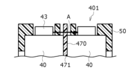
図5は、参考例の電池パック401における突出端子43周辺の断面図であり、図6は、電池パック1における突出端子43周辺の断面図である。図5に示すように、電池パック401は、隣り合う2つの電池40の間を仕切る仕切部材470が頭部を有さなくて板状の仕切部471しか有さず、突出端子43の周辺も板状の仕切部471で仕切られている点が、電池パック1と異なる。
FIG. 5 is a cross-sectional view around the projecting terminal 43 in the battery pack 401 of the reference example, and FIG. 6 is a cross-sectional view around the projecting terminal 43 in the battery pack 1 . As shown in FIG. 5 , in battery pack 401 , partition member 470 that partitions two adjacent batteries 40 does not have a head but has only plate-like partition 471 . It differs from the battery pack 1 in that it is partitioned by a plate-like partition 471 .
参考例の電池パック401において、1の電池40が異常発熱して排気弁が動作したとする。すると、突出端子43周辺から高温のガスや噴出物の一部が図5に矢印Aで示す仕切部471側に噴射される。このとき、仕切部471の厚さが薄いと、仕切部471に孔があいて、高温のガスや噴出物が隣の電池40に到達して、異常発熱した電池40の影響が、隣の電池40に及ぶ虞がある。したがって、仕切部471の厚さを薄くできず、電池パック401をコンパクトにしにくい。
Assume that in the battery pack 401 of the reference example, one battery 40 abnormally heats up and the exhaust valve operates. Then, a part of the high-temperature gas and ejected substance is jetted from the vicinity of the projecting terminal 43 toward the partition portion 471 indicated by the arrow A in FIG. At this time, if the thickness of the partition 471 is thin, a hole is formed in the partition 471, and high-temperature gas or spouted matter reaches the adjacent battery 40, and the abnormally heated battery 40 affects the adjacent battery. There is a risk of as many as 40. Therefore, the thickness of the partition portion 471 cannot be reduced, and it is difficult to make the battery pack 401 compact.
これに対し、電池パック1によれば、仕切部材70が、仕切部71の高さ方向の一方側に仕切部71より肉厚のブロック状の頭部72を有するので、1の電池40が異常発熱して排気弁が動作したとしても、突出端子43周辺から図6に矢印Bで示す方向に放出された高温のガスや噴出物を頭部72でブロックできて、突出端子43周辺から放出された高温のガスや噴出物が隣の電池40に到達することを効果的に抑制できる。
In contrast, according to the battery pack 1, the partition member 70 has the block-shaped head portion 72 thicker than the partition portion 71 on one side in the height direction of the partition portion 71, so that one battery 40 is abnormal. Even if the heat is generated and the exhaust valve is operated, the head 72 can block high-temperature gas and spouts emitted from the vicinity of the protruding terminal 43 in the direction indicated by the arrow B in FIG. Therefore, it is possible to effectively prevent the high-temperature gas and ejected matter from reaching the adjacent battery 40 .
更には、頭部72で安全性を確保できるので、隣り合う電池40の間を仕切る仕切部71の厚さを頭部72に必要な肉厚と独立して設定できるので、電池40の並び方向(直交方向)の寸法も大きくする必要がなく、電池パック1をコンパクトに構成し易い。
Furthermore, since the safety can be ensured by the head 72, the thickness of the partition 71 that partitions the adjacent batteries 40 can be set independently of the thickness required for the head 72. It is not necessary to increase the dimension (perpendicular direction), and the battery pack 1 can be easily configured to be compact.
よって、電池パック1によれば、互いに相反してトレードオフの関係にある、隣り合う電池間距離を短くし易くて電池パック1をコンパクトにし易いという作用効果と、1の電池の異常発熱の影響が他の電池に及ぶことを効果的に抑制できて、安全性を高くし易いという作用効果の両方を同時に実現することができる。
Therefore, according to the battery pack 1, the effect that the distance between adjacent batteries can be easily shortened and the battery pack 1 can be easily made compact, and the influence of abnormal heat generation of one battery, which are in a mutually contradictory trade-off relationship. It is possible to effectively suppress the influence of the contamination on other batteries, and simultaneously achieve both the operational effects of facilitating a high level of safety.
また、頭部72は、仕切部71の厚さ方向の両側に突出して隣り合う2つの電池40,40のうちの一方に高さ方向に重なる第1部分91と、上記2つの電池40,40のうちの他方に高さ方向に重なる第2部分92とを含んでもよい。
The head portion 72 includes a first portion 91 that protrudes on both sides in the thickness direction of the partition portion 71 and overlaps one of the two adjacent batteries 40, 40 in the height direction, and a first portion 91 that overlaps the two batteries 40, 40 and a second portion 92 overlapping in the height direction with the other of the two.
本構成によれば、頭部72における上記厚さ方向の寸法を大きくできる。したがって、一方の電池40が異常発熱した際に、その影響が他方の電池40に及ぶことを抑制する効果を顕著なものにできる。なお、頭部72が、2つの電池40,40のうちの一方に高さ方向に重なる第1部分91と、2つの電池40,40のうちの他方に高さ方向に重なる第2部分92とを有する場合について説明した。しかし、頭部は、隣り合う2つの電池のうちの一方に高さ方向に重なる部分を有する一方、2つの電池のうちの他方に高さ方向に重なる部分を有さなくてもよい。
According to this configuration, the dimension of the head 72 in the thickness direction can be increased. Therefore, when one battery 40 generates abnormal heat, the effect of suppressing the other battery 40 from being affected can be made remarkable. The head 72 has a first portion 91 that overlaps one of the two batteries 40 and 40 in the height direction, and a second portion 92 that overlaps the other of the two batteries 40 and 40 in the height direction. The case of having However, the head may have a portion that overlaps one of the two adjacent batteries in the height direction and no portion that overlaps the other of the two batteries in the height direction.
また、仕切部材70が、頭部72から高さ方向に延在する高さ方向延在部77と、高さ方向延在部77における高さ方向の頭部72側とは反対側の端部に接続されると共に頭部72に隙間を介して高さ方向に対向する対向部78とを有してもよい。また、頭部72、高さ方向延在部77、及び対向部78が、スリット84を画定してもよい。そして、電池パック1が、少なくとも一部がスリット84に収容される集電板67を備えてもよい。
In addition, the partition member 70 has a height direction extension portion 77 extending in the height direction from the head portion 72 and an end portion of the height direction extension portion 77 opposite to the head portion 72 side in the height direction. and facing the head 72 in the height direction with a gap therebetween. The head 72 , the heightwise extending portion 77 and the facing portion 78 may also define the slit 84 . Then, the battery pack 1 may include the collector plate 67 at least partially accommodated in the slit 84 .
本構成によれば、集電板67を用いて隣り合う電池40,40を容易に電気的に接続できる。なお、本実施形態では、隣り合う電池40,40が同じ向きに配置されて、隣り合う電池40,40が集電板67により並列接続された。しかし、隣り合う電池が互いに逆向きに配置されて、隣り合う電池が集電板により直列接続されてもよい。
According to this configuration, the adjacent batteries 40 , 40 can be easily electrically connected using the current collector plate 67 . In this embodiment, the adjacent batteries 40 , 40 are arranged in the same direction, and the adjacent batteries 40 , 40 are connected in parallel by the current collector plate 67 . However, adjacent batteries may be arranged opposite to each other, and adjacent batteries may be connected in series by current collector plates.
また、電池パック1が、少なくとも一部がスリット84における集電板67と対向部78の間に収容され、耐火性を有するシート部材68を備えてもよい。
Also, the battery pack 1 may include a fire-resistant sheet member 68 at least partially accommodated between the collector plate 67 and the facing portion 78 in the slit 84 .
本構成によれば、シート部材68によって、1の電池の異常発熱の影響が他の電池に及ぶことを更に効果的に抑制でき、電池パック1を更に安全なものにできる。なお、耐火性を有するシート部材が存在せず、スリットに、集電板の一部のみを収容する構成でもよい。
According to this configuration, the sheet member 68 can more effectively suppress the influence of abnormal heat generation of one battery from affecting the other batteries, and the battery pack 1 can be made even safer. It should be noted that a structure in which only a part of the current collector plate is accommodated in the slit without the sheet member having fire resistance may be used.
また、電池パック1が、仕切部材70における高さ方向の少なくとも一方側の端部に接触する仕切接触部を備えてもよい。
Also, the battery pack 1 may include a partition contact portion that contacts at least one end of the partition member 70 in the height direction.
本構成によれば、仕切部材70の頭部72側の先端と、その先端に対応する部位との間に隙間が生じないようにできる。したがって、1の電池40の突出端子43付近から排出された高温ガスや噴出物が仕切部材70の頭部72側の先端の上側を迂回して隣の電池40に到達する迂回経路を遮断できる。よって、非常に安全な電池パック1を実現できる。
According to this configuration, it is possible to prevent a gap from being generated between the tip of the partition member 70 on the head 72 side and the portion corresponding to the tip. Therefore, it is possible to cut off a detour route in which high-temperature gas and ejected substances discharged from the vicinity of the projecting terminal 43 of one battery 40 detour above the tip of the partition member 70 on the head 72 side and reach the adjacent battery 40 . Therefore, a very safe battery pack 1 can be realized.
また、仕切部材70が、拘束部材50,60よりも熱伝導率が低くてもよい。
Also, the partition member 70 may have a lower thermal conductivity than the restraining members 50 and 60.
本構成によれば、異常発熱した電池40からの熱を熱伝導率が高い拘束部材50,60を介して外部に効果的に放熱できる。よって、異常発熱した電池40の影響が他の電池40に及ぶことを効果的に抑制できる。
According to this configuration, the heat from the abnormally heated battery 40 can be effectively radiated to the outside through the restraining members 50 and 60 with high thermal conductivity. Therefore, it is possible to effectively prevent the other batteries 40 from being affected by the abnormally heated battery 40 .
また、電池パック1が、拘束部材50,60を収容するケース5を備えてもよい。
Also, the battery pack 1 may include a case 5 that accommodates the restraining members 50 and 60 .
本構成によれば、電池パック1に複数の電池ブロック10を収容し易い。よって、電池パック1の電圧を高くし易く、電池パック1の容量も大きくし易い。
According to this configuration, it is easy to accommodate a plurality of battery blocks 10 in the battery pack 1 . Therefore, the voltage of the battery pack 1 can be easily increased, and the capacity of the battery pack 1 can be easily increased.
なお、本開示は、上記実施形態およびその変形例に限定されるものではなく、本願の請求の範囲に記載された事項およびその均等な範囲において種々の改良や変更が可能である。
It should be noted that the present disclosure is not limited to the above embodiments and modifications thereof, and various improvements and modifications are possible within the scope of the claims of the present application and their equivalents.
例えば、上記実施形態では、仕切部材70の熱伝導率が、拘束部材50,60の熱伝導率よりも低い場合について説明した。しかし、仕切部材の熱伝導率は、拘束部材の熱伝導率と同一でもよく、拘束部材の熱伝導率よりも高くてもよい。
For example, in the above embodiment, the case where the thermal conductivity of the partition member 70 is lower than the thermal conductivity of the restraining members 50 and 60 has been described. However, the thermal conductivity of the partition member may be the same as the thermal conductivity of the restraint member, or may be higher than the thermal conductivity of the restraint member.
また、仕切部材70が、頭部72、高さ方向延在部77、及び対向部78を有する場合について説明した。しかし、図7、すなわち、変形例の電池パック101の突出端子43周辺の断面図に示すように、仕切部材170は、断面においてT字形状を有してもよい。すなわち、仕切部材170は、高さ方向延在部、及び対向部を有さなくてもよく、頭部72が仕切部材170の高さ方向一方側の端部を構成してもよい。なお、図6においては、スリット84を構成する、高さ方向延在部77と対向部78の図示を省略している。
Also, the case where the partition member 70 has the head portion 72, the height direction extending portion 77, and the facing portion 78 has been described. However, partition member 170 may have a T-shape in cross section, as shown in FIG. That is, the partition member 170 may not have the height direction extending portion and the facing portion, and the head portion 72 may form one end portion of the partition member 170 in the height direction. 6, illustration of the height-direction extending portion 77 and the facing portion 78 that constitute the slit 84 is omitted.
また、電池パック1が拘束部材50,60を収容するケース5を備える場合について説明したが、拘束部材が、ケースである構成でもよい。
Also, although the case where the battery pack 1 includes the case 5 that accommodates the restraining members 50 and 60 has been described, the restraining member may be a case.
また、仕切部材70を、同一の樹脂材料で一体成形する場合について説明した。しかし、仕切部材は、仕切部と頭部が異なる材料で構成されてもよい。例えば、仕切部材は、2色成形で一体に作成されてもよい。又は、仕切部材は、同一材料で作成された仕切部と、仕切部と異なる材料で構成された頭部とを、接合手段、例えば、接着剤や溶着部等によって接合することで、一体にしてもよい。この場合において、仕切部及び頭部のうちの一方を、マイカ等の無機鉱物、又は樹脂材料にマイカ等の無機鉱物を混入した材料で構成してもよい。又は、仕切部及び頭部のうちの一方を、熱硬化性樹脂(例えば、フェノール樹脂、不飽和ポリエステル樹脂、シリコーン樹脂等)または、セラミック繊維のシート材料で構成してもよい。
Also, the case where the partition member 70 is integrally molded with the same resin material has been described. However, the partition member may be made of a different material for the partition portion and the head portion. For example, the partition member may be made integrally by two-color molding. Alternatively, the partition member is formed by joining the partition made of the same material and the head made of a material different from that of the partition by a joining means such as an adhesive or a welded portion. good too. In this case, one of the partition and the head may be made of an inorganic mineral such as mica, or a material obtained by mixing an inorganic mineral such as mica into a resin material. Alternatively, one of the partition and the head may be made of a thermosetting resin (for example, phenolic resin, unsaturated polyester resin, silicone resin, etc.) or ceramic fiber sheet material.
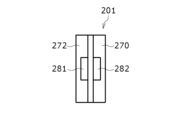
また、仕切部材は、電池40に対して相対移動不可になっていてもよい。図8は、他の変形例の電池パック201における図7に対応する断面図であり、図9は、電池パック201の仕切部材270を高さ方向の頭部272とは反対側から見たときの平面図である。図8及び図9に示すように、頭部272は、第1部分291における電池40に対向する端面に第1凹部255を有すると共に第2部分292における電池40に対向する端面に第2凹部256を有してもよい。また、第1及び第2凹部255,256の夫々に固定手段281,282、例えば、接着剤、粘着剤、又は両面テープ等の粘着シートを収容してもよい。そして、第1固定手段281を第1凹部255の内面と電池40の端面の両方に固定すると共に第2固定手段282を第2凹部256の内面と電池40の端面の両方に固定してもよい。
Also, the partition member may be immovable relative to the battery 40 . FIG. 8 is a cross-sectional view corresponding to FIG. 7 in battery pack 201 of another modification, and FIG. 9 is a view of partition member 270 of battery pack 201 from the opposite side of head 272 in the height direction. is a plan view of the. 8 and 9, the head 272 has a first recess 255 on the end face of the first portion 291 facing the battery 40 and a second recess 256 on the end face of the second portion 292 facing the battery 40. As shown in FIGS. may have In addition, fixing means 281, 282, for example, an adhesive, an adhesive, or an adhesive sheet such as double-sided tape may be accommodated in the first and second recesses 255, 256, respectively. The first fixing means 281 may be fixed to both the inner surface of the first recess 255 and the end surface of the battery 40, and the second fixing means 282 may be fixed to both the inner surface of the second recess 256 and the end surface of the battery 40. .
このようにすれば、仕切部材270を隣り合う2つの電池40の両方に固定できて、仕切部材270が隣り合う2つの電池40の夫々に対して相対移動することを禁止でき、各電池40が仕切部材270に対して相対回転することを防止できる。なお、頭部の第1部分における電池側の端面に凹部を設けずに、頭部の第1部分と電池の端面の間に第1固定手段、例えば、接着剤、粘着剤、又は両面テープ等の粘着シートを配置してもよい。また、同様に、頭部の第2部分における電池側の端面に凹部を設けずに、頭部の第2部分と電池の端面の間に第2固定手段、例えば、接着剤、粘着剤、又は両面テープ等の粘着シートを配置してもよい。このようにして、第1部分を第1電池に固定すると共に、第2部分を第2電池に固定してもよい。
In this way, the partition member 270 can be fixed to both of the two adjacent batteries 40, the partition member 270 can be prevented from moving relative to each of the two adjacent batteries 40, and each battery 40 can be Relative rotation with respect to the partition member 270 can be prevented. A first fixing means such as an adhesive, a pressure-sensitive adhesive, or a double-sided tape is inserted between the first portion of the head portion and the end surface of the battery without providing a concave portion on the end surface of the first portion of the head portion on the battery side. of adhesive sheets may be placed. Similarly, a second fixing means such as an adhesive, a pressure-sensitive adhesive, or the like is provided between the second portion of the head portion and the end surface of the battery without providing a concave portion on the end surface of the second portion of the head portion on the battery side. An adhesive sheet such as double-sided tape may be arranged. In this manner, the first portion may be secured to the first battery and the second portion may be secured to the second battery.
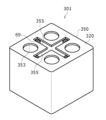
また、電池ブロックが整列配置された2つの電池と2つの拘束部材を有する場合について説明した。しかし、各電池ブロックは、配列配置された3以上の電池を備えてもよく、1つのみの拘束部材を備えてもよい。図10は、更なる変形例の電池パック301の拘束部材350の斜視図であり、図11は、電池パック301の拘束部材350の天板部320の外面321を高さ方向から見たときの平面図である。また、図12は、電池パック301の天板部320の内面322を高さ方向から見たときの平面図であり、図13は、電池パック301の仕切部材370の斜視図である。
Also, the case where the battery block has two batteries and two restraining members arranged in alignment has been described. However, each battery block may have three or more batteries arranged in an array, or may have only one restraining member. FIG. 10 is a perspective view of restraining member 350 of battery pack 301 of a further modified example, and FIG. It is a top view. 12 is a plan view of inner surface 322 of top plate portion 320 of battery pack 301 viewed from the height direction, and FIG. 13 is a perspective view of partition member 370 of battery pack 301. As shown in FIG.
図10に示すように、拘束部材350は、略直方体の内部室を有すると共に、略直方体外観を有してもよい。また、図10~図12に示すように、天板部320にプラス形状(+形状)の仕切設置孔355を設けてもよく、仕切設置孔355の4つの端部の夫々に、図3を用いて説明した第1突出部56、第2突出部57、及び貫通凹部59を設けてもよい。また、矩形の平面形状を有する天板部320においてプラス形状の仕切設置孔355で区切られた4つの部位の夫々に電池40の突出端子43(あるいは排気弁)を収容する円筒孔353を設けてもよい。そして、底板部(図示せず)にも、4つの円筒孔353に高さ方向に対向する対向位置の周辺に円筒孔(図示せず)を設けてもよい。
As shown in FIG. 10, the restraining member 350 may have a substantially rectangular parallelepiped internal chamber and a substantially rectangular parallelepiped external appearance. In addition, as shown in FIGS. 10 to 12, a plus-shaped (+-shaped) partition installation hole 355 may be provided in the top plate portion 320, and each of the four ends of the partition installation hole 355 may have a shape as shown in FIG. The first projecting portion 56, the second projecting portion 57, and the through recess 59 described with reference to FIG. In addition, cylindrical holes 353 for accommodating protruding terminals 43 (or exhaust valves) of the batteries 40 are provided in each of four portions separated by plus-shaped partition installation holes 355 in the top plate portion 320 having a rectangular planar shape. good too. Then, the bottom plate portion (not shown) may also be provided with cylindrical holes (not shown) around positions facing the four cylindrical holes 353 in the height direction.
また、図12に示すように、天板部320の内面322と底板部の内面に電池40の高さ方向の端部を収容する凹部315を設けてもよく、この凹部315が電池40の円筒外周面の一部に対応する形状の電池拘束面318を有してもよい。また、図13に示すように、仕切部材370が、一体構造を有し、高さ方向から見たときの平面視がプラス形状の仕切部371と、高さ方向から見たときの平面視がプラス形状の頭部372を含んでもよい。また、仕切部371が、端面形状が正方形の四角柱と、四角柱の各側面から90度の間隔をおいて放射状に延びる4つの板状部340を有してもよい。また、頭部372が、端面形状が正方形の第1板状部345と、第1板状部345の各側面から90度の間隔をおいて放射状に延びる4つの第2板状部347を有してもよい。
Further, as shown in FIG. 12, recesses 315 for accommodating the ends of the batteries 40 in the height direction may be provided on the inner surface 322 of the top plate 320 and the inner surface of the bottom plate. It may have a battery restraint surface 318 having a shape corresponding to a part of the outer peripheral surface. Moreover, as shown in FIG. 13, the partition member 370 has an integral structure, and the partition portion 371 has a positive shape when viewed from the height direction, and the partition portion 371 has a positive shape when viewed from the height direction. A plus-shaped head 372 may be included. Moreover, the partition part 371 may have a quadrangular prism whose end face shape is a square and four plate-shaped parts 340 radially extending from each side face of the quadrangular prism at intervals of 90 degrees. The head portion 372 has a first plate-shaped portion 345 with a square end face shape and four second plate-shaped portions 347 radially extending from each side surface of the first plate-shaped portion 345 at intervals of 90 degrees. You may
また、頭部372の第2板状部347の高さ方向の片側端部と仕切部371の板状部340の高さ方向の片側端部とを繋げてもよい。また、対をなす、頭部372の第2板状部347と、仕切部371の板状部340とが、図2,図3等を用いて説明した上述の頭部72と仕切部71の一体構造と同一の構造を有してもよい。つまり、頭部372の第2板状部347は、仕切部371の板状部340の厚さ方向の両側に突出する部分を有してもよい。また、頭部372の底面が第1及び第2突出部56,57に接触するまで、仕切部371の各板状部340を貫通凹部59に圧入すると共に、頭部372の各第2板状部347を頭部収容室69(図10参照)に収容してもよい。このようにすれば、2行2列に整列配置される4つの電池40を有する電池ブロックを構成できる。
Alternatively, one side end in the height direction of the second plate-like portion 347 of the head portion 372 and one side end in the height direction of the plate-like portion 340 of the partition portion 371 may be connected. Also, the second plate-shaped portion 347 of the head portion 372 and the plate-shaped portion 340 of the partition portion 371, which form a pair, are the same as the head portion 72 and the partition portion 71 described above with reference to FIGS. It may have the same structure as the one-piece structure. That is, the second plate-like portion 347 of the head portion 372 may have portions that protrude on both sides in the thickness direction of the plate-like portion 340 of the partition portion 371 . Further, each plate-like portion 340 of the partition portion 371 is press-fitted into the through recess 59 until the bottom surface of the head portion 372 contacts the first and second projecting portions 56 and 57, and each second plate-like portion of the head portion 372 is pressed. The portion 347 may be housed in the head housing chamber 69 (see FIG. 10). In this way, a battery block having four batteries 40 arranged in two rows and two columns can be constructed.
また、隣り合う電池は、高さ方向の存在位置が異なっていてもよい。例えば、隣り合う電池を互い違いに配置する場合、両端で一方の電池の突出端子が他の電池の外装缶の底よりも高さ方向に突出する配置でもよい。また、図2に示すように、頭部72の高さ方向の天面73の全てと、頭部72の底面74の全てが、略平行になっている場合について説明したが、そのようになっていなくてもよい。仕切部材の頭部は、高さ方向に電池の排気弁の位置より突出し、かつ仕切部の厚さ方向に突出して2つの電池のうち少なくとも一方に高さ方向に重なる部分を含んでいれば、如何なる形状及び構造でもよい。
Also, adjacent batteries may have different positions in the height direction. For example, when adjacent batteries are arranged in a staggered manner, the protruding terminals of one battery may protrude in the height direction from the bottom of the outer can of the other battery at both ends. Also, as shown in FIG. 2, the case where all of the top surface 73 of the head 72 in the height direction and all of the bottom surface 74 of the head 72 are substantially parallel has been described, but this is not the case. It doesn't have to be. If the head portion of the partition member protrudes in the height direction from the position of the exhaust valve of the battery and includes a portion that protrudes in the thickness direction of the partition portion and overlaps at least one of the two batteries in the height direction, It can be of any shape and construction.
また、仕切部材70が、高さ方向の電池40の突出端子43側に頭部72を有する場合について説明した。しかし、仕切部材は、仕切部の高さ方向の電池の突出端子側とは反対側に頭部を有してもよい。電池は、排気弁を外装缶の底部に有する場合がある。そのような場合に、その構造を採用すると、外装缶の底部から放出された高温ガスや噴出物が隣の電池に到達することを効果的に抑制できる。又は、仕切部材は、仕切部の高さ方向の両側に頭部を有してもよい。電池は、排気弁を封口体と外装缶の底部の2箇所に有する場合がある。そのような場合に、その構造を採用すると、外装缶の封口体や底部から放出された高温ガスや噴出物が隣の電池に到達することを効果的に抑制できる。
Also, the case where the partition member 70 has the head 72 on the protruding terminal 43 side of the battery 40 in the height direction has been described. However, the partition member may have a head on the side opposite to the projecting terminal side of the battery in the height direction of the partition. The battery may have a vent valve at the bottom of the outer can. In such a case, if this structure is adopted, it is possible to effectively prevent the high-temperature gas and ejected substances discharged from the bottom of the outer can from reaching the adjacent battery. Alternatively, the partition member may have heads on both sides of the partition in the height direction. A battery may have exhaust valves at two locations, the seal and the bottom of the outer can. In such a case, by adopting this structure, it is possible to effectively prevent the high-temperature gas and spouts released from the sealing member and the bottom of the outer can from reaching the adjacent battery.
1,101,201,301,401 電池パック、 5 ケース、 10 電池ブロック、 40 電池、 50 第1拘束部材、 51 側方部、 60 第2拘束部材、 61 側方部、 67 集電板、 68 シート部材、 70,170,270,370,470 仕切部材、 71,371,471 仕切部、 72,272,372 頭部、 77 高さ方向延在部、 78 対向部、 84 スリット、 91,291 第1部分、 92,292 第2部分、 98,99 仕切接触部、 281 第1固定手段、 282 第2固定手段、 350 拘束部材。
1, 101, 201, 301, 401 battery pack, 5 case, 10 battery block, 40 battery, 50 first restraint member, 51 side portion, 60 second restraint member, 61 side portion, 67 current collector, 68 Sheet member 70, 170, 270, 370, 470 Partition member 71, 371, 471 Partition section 72, 272, 372 Head section 77 Height direction extension section 78 Opposing section 84 Slit 91, 291 Section 1 part, 92, 292 second part, 98, 99 partition contact part, 281 first fixing means, 282 second fixing means, 350 restraining member.
Claims (9)
- 整列配置された複数の電池における高さ方向の少なくとも一部を取り囲むように配置される側方部を含む拘束部材と、隣り合う2つの前記電池の間を仕切る仕切部、及び前記仕切部の前記高さ方向の少なくとも一方側の端部に接続される頭部を有する仕切部材と、を備え、
前記頭部は、前記高さ方向に前記電池の排気弁の位置より突出し、かつ前記仕切部の厚さ方向に突出して前記2つの電池のうち少なくとも一方に前記高さ方向に重なる部分を含む、電池パック。 a restraining member including a side portion arranged to surround at least a portion of a plurality of aligned batteries in a height direction; a partition partitioning between two adjacent batteries; a partition member having a head connected to at least one end in the height direction,
The head includes a portion that protrudes in the height direction from the position of the exhaust valve of the battery, protrudes in the thickness direction of the partition portion, and overlaps at least one of the two batteries in the height direction. battery pack. - 前記頭部は、前記仕切部の厚さ方向の両側に突出して前記2つの電池のうちの一方に前記高さ方向に重なる第1部分と、前記2つの電池のうちの他方に前記高さ方向に重なる第2部分とを含む、請求項1に記載の電池パック。 The head includes a first portion that protrudes on both sides of the partition in the thickness direction and overlaps one of the two batteries in the height direction, and a first portion that overlaps the other of the two batteries in the height direction. 2. The battery pack of claim 1, comprising a second portion overlapping the .
- 前記仕切部材が、前記頭部から前記高さ方向に延在する高さ方向延在部と、前記高さ方向延在部における前記高さ方向の前記頭部側とは反対側の端部に接続されると共に前記頭部に隙間を介して前記高さ方向に対向する対向部とを有して、前記頭部、前記高さ方向延在部、及び前記対向部が、スリットを画定し、
少なくとも一部が前記スリットに収容される集電板を備える、請求項1または2に記載の電池パック。 The partition member is provided at a height direction extension portion extending from the head portion in the height direction and at an end portion of the height direction extension portion opposite to the head side in the height direction. and a facing portion connected to and facing the head portion in the height direction with a gap therebetween, wherein the head portion, the height direction extending portion, and the facing portion define a slit,
3. The battery pack according to claim 1, comprising a collector plate at least part of which is accommodated in said slit. - 少なくとも一部が前記スリットにおける前記集電板と前記対向部の間に収容され、耐火性を有するシート部材を備える、請求項3に記載の電池パック。 4. The battery pack according to claim 3, further comprising a fire-resistant sheet member, at least a part of which is housed between the collector plate and the facing portion of the slit.
- 前記仕切部材における前記高さ方向の少なくとも一方側の端部に接触する仕切接触部を備える、請求項1から4のいずれか1つに記載の電池パック。 The battery pack according to any one of claims 1 to 4, comprising a partition contact portion that contacts at least one end of the partition member in the height direction.
- 前記仕切部材が、前記拘束部材よりも熱伝導率が低い、請求項1から5のいずれか1つに記載の電池パック。 The battery pack according to any one of claims 1 to 5, wherein said partition member has lower thermal conductivity than said restraint member.
- 前記第1部分と前記2つの電池のうちの一方との間に配置される第1固定手段と、
前記第2部分と前記2つの電池のうちの他方との間に配置される第2固定手段と、
を備える、請求項2から6のいずれか1つに記載の電池パック。 a first securing means disposed between said first portion and one of said two batteries;
a second fixing means disposed between the second portion and the other of the two batteries;
The battery pack according to any one of claims 2 to 6, comprising: - 前記拘束部材を収容するケースを備える、請求項1から7のいずれか1つに記載の電池パック。 The battery pack according to any one of claims 1 to 7, comprising a case that accommodates the restraining member.
- 前記拘束部材が、ケースを構成する、請求項1から7のいずれか1つに記載の電池パック。 The battery pack according to any one of claims 1 to 7, wherein the restraining member constitutes a case.
Applications Claiming Priority (2)
| Application Number | Priority Date | Filing Date | Title |
|---|---|---|---|
| JP2021211278 | 2021-12-24 | ||
| JP2021-211278 | 2021-12-24 |
Publications (1)
| Publication Number | Publication Date |
|---|---|
| WO2023120437A1 true WO2023120437A1 (en) | 2023-06-29 |
Family
ID=86902708
Family Applications (1)
| Application Number | Title | Priority Date | Filing Date |
|---|---|---|---|
| PCT/JP2022/046502 WO2023120437A1 (en) | 2021-12-24 | 2022-12-16 | Battery pack |
Country Status (1)
| Country | Link |
|---|---|
| WO (1) | WO2023120437A1 (en) |
Cited By (1)
| Publication number | Priority date | Publication date | Assignee | Title |
|---|---|---|---|---|
| WO2024024422A1 (en) * | 2022-07-26 | 2024-02-01 | パナソニックIpマネジメント株式会社 | Battery pack |
Citations (5)
| Publication number | Priority date | Publication date | Assignee | Title |
|---|---|---|---|---|
| JP2012033464A (en) * | 2010-07-02 | 2012-02-16 | Sanyo Electric Co Ltd | Battery pack |
| JP2016046234A (en) * | 2014-08-27 | 2016-04-04 | 三洋電機株式会社 | Battery system |
| WO2018225609A1 (en) * | 2017-06-08 | 2018-12-13 | 三洋電機株式会社 | Battery module |
| JP2018206605A (en) * | 2017-06-05 | 2018-12-27 | 積水化学工業株式会社 | Thermal runaway prevention sheet |
| JP2020166991A (en) * | 2019-03-28 | 2020-10-08 | 三洋電機株式会社 | Battery pack |
-
2022
- 2022-12-16 WO PCT/JP2022/046502 patent/WO2023120437A1/en active Application Filing
Patent Citations (5)
| Publication number | Priority date | Publication date | Assignee | Title |
|---|---|---|---|---|
| JP2012033464A (en) * | 2010-07-02 | 2012-02-16 | Sanyo Electric Co Ltd | Battery pack |
| JP2016046234A (en) * | 2014-08-27 | 2016-04-04 | 三洋電機株式会社 | Battery system |
| JP2018206605A (en) * | 2017-06-05 | 2018-12-27 | 積水化学工業株式会社 | Thermal runaway prevention sheet |
| WO2018225609A1 (en) * | 2017-06-08 | 2018-12-13 | 三洋電機株式会社 | Battery module |
| JP2020166991A (en) * | 2019-03-28 | 2020-10-08 | 三洋電機株式会社 | Battery pack |
Cited By (1)
| Publication number | Priority date | Publication date | Assignee | Title |
|---|---|---|---|---|
| WO2024024422A1 (en) * | 2022-07-26 | 2024-02-01 | パナソニックIpマネジメント株式会社 | Battery pack |
Similar Documents
| Publication | Publication Date | Title |
|---|---|---|
| US11128012B2 (en) | Battery module including thermal insulator disposed between battery blocks | |
| JP7186371B2 (en) | battery block | |
| US20130136969A1 (en) | Battery module and battery assembly used in battery module | |
| JP2006278334A (en) | Battery module | |
| JP4916183B2 (en) | Pack battery | |
| JP6685001B2 (en) | Battery pack | |
| WO2023120437A1 (en) | Battery pack | |
| WO2016199563A1 (en) | Battery module | |
| JP7042174B2 (en) | Battery pack | |
| WO2012073440A1 (en) | Battery module | |
| KR20120061004A (en) | Battery Pack | |
| US20210184190A1 (en) | Battery pack | |
| US11721864B2 (en) | Battery pack with separated cooling channels and discharge path | |
| JP4712929B2 (en) | Abnormal temperature detection device for battery pack | |
| JP7276896B2 (en) | battery module | |
| JP2016015253A (en) | Power storage module | |
| JP2018133152A (en) | Battery module and battery pack | |
| JP7418409B2 (en) | battery module | |
| CN111033810B (en) | Battery module | |
| JP2003331803A (en) | Battery pack | |
| JP7325442B2 (en) | battery module | |
| JP2022062288A (en) | Battery module | |
| WO2020137411A1 (en) | Power storage device | |
| JP2008243783A (en) | Battery pack | |
| WO2020059298A1 (en) | Battery module |
Legal Events
| Date | Code | Title | Description |
|---|---|---|---|
| 121 | Ep: the epo has been informed by wipo that ep was designated in this application |
Ref document number: 22911140 Country of ref document: EP Kind code of ref document: A1 |
|
| WWE | Wipo information: entry into national phase |
Ref document number: 2023569410 Country of ref document: JP |