KR20120061004A - Battery Pack - Google Patents
Battery Pack Download PDFInfo
- Publication number
- KR20120061004A KR20120061004A KR1020100107792A KR20100107792A KR20120061004A KR 20120061004 A KR20120061004 A KR 20120061004A KR 1020100107792 A KR1020100107792 A KR 1020100107792A KR 20100107792 A KR20100107792 A KR 20100107792A KR 20120061004 A KR20120061004 A KR 20120061004A
- Authority
- KR
- South Korea
- Prior art keywords
- positive temperature
- internal terminal
- battery pack
- heat transfer
- battery cell
- Prior art date
Links
Images


Classifications
-
- H—ELECTRICITY
- H01—ELECTRIC ELEMENTS
- H01M—PROCESSES OR MEANS, e.g. BATTERIES, FOR THE DIRECT CONVERSION OF CHEMICAL ENERGY INTO ELECTRICAL ENERGY
- H01M50/00—Constructional details or processes of manufacture of the non-active parts of electrochemical cells other than fuel cells, e.g. hybrid cells
- H01M50/50—Current conducting connections for cells or batteries
- H01M50/572—Means for preventing undesired use or discharge
-
- H—ELECTRICITY
- H01—ELECTRIC ELEMENTS
- H01M—PROCESSES OR MEANS, e.g. BATTERIES, FOR THE DIRECT CONVERSION OF CHEMICAL ENERGY INTO ELECTRICAL ENERGY
- H01M10/00—Secondary cells; Manufacture thereof
- H01M10/42—Methods or arrangements for servicing or maintenance of secondary cells or secondary half-cells
- H01M10/425—Structural combination with electronic components, e.g. electronic circuits integrated to the outside of the casing
- H01M10/4257—Smart batteries, e.g. electronic circuits inside the housing of the cells or batteries
-
- H—ELECTRICITY
- H01—ELECTRIC ELEMENTS
- H01M—PROCESSES OR MEANS, e.g. BATTERIES, FOR THE DIRECT CONVERSION OF CHEMICAL ENERGY INTO ELECTRICAL ENERGY
- H01M10/00—Secondary cells; Manufacture thereof
- H01M10/05—Accumulators with non-aqueous electrolyte
- H01M10/052—Li-accumulators
- H01M10/0525—Rocking-chair batteries, i.e. batteries with lithium insertion or intercalation in both electrodes; Lithium-ion batteries
-
- H—ELECTRICITY
- H01—ELECTRIC ELEMENTS
- H01M—PROCESSES OR MEANS, e.g. BATTERIES, FOR THE DIRECT CONVERSION OF CHEMICAL ENERGY INTO ELECTRICAL ENERGY
- H01M10/00—Secondary cells; Manufacture thereof
- H01M10/60—Heating or cooling; Temperature control
- H01M10/63—Control systems
-
- H—ELECTRICITY
- H01—ELECTRIC ELEMENTS
- H01M—PROCESSES OR MEANS, e.g. BATTERIES, FOR THE DIRECT CONVERSION OF CHEMICAL ENERGY INTO ELECTRICAL ENERGY
- H01M50/00—Constructional details or processes of manufacture of the non-active parts of electrochemical cells other than fuel cells, e.g. hybrid cells
- H01M50/10—Primary casings, jackets or wrappings of a single cell or a single battery
- H01M50/102—Primary casings, jackets or wrappings of a single cell or a single battery characterised by their shape or physical structure
- H01M50/105—Pouches or flexible bags
-
- H—ELECTRICITY
- H01—ELECTRIC ELEMENTS
- H01M—PROCESSES OR MEANS, e.g. BATTERIES, FOR THE DIRECT CONVERSION OF CHEMICAL ENERGY INTO ELECTRICAL ENERGY
- H01M50/00—Constructional details or processes of manufacture of the non-active parts of electrochemical cells other than fuel cells, e.g. hybrid cells
- H01M50/50—Current conducting connections for cells or batteries
- H01M50/572—Means for preventing undesired use or discharge
- H01M50/574—Devices or arrangements for the interruption of current
- H01M50/581—Devices or arrangements for the interruption of current in response to temperature
-
- Y—GENERAL TAGGING OF NEW TECHNOLOGICAL DEVELOPMENTS; GENERAL TAGGING OF CROSS-SECTIONAL TECHNOLOGIES SPANNING OVER SEVERAL SECTIONS OF THE IPC; TECHNICAL SUBJECTS COVERED BY FORMER USPC CROSS-REFERENCE ART COLLECTIONS [XRACs] AND DIGESTS
- Y02—TECHNOLOGIES OR APPLICATIONS FOR MITIGATION OR ADAPTATION AGAINST CLIMATE CHANGE
- Y02E—REDUCTION OF GREENHOUSE GAS [GHG] EMISSIONS, RELATED TO ENERGY GENERATION, TRANSMISSION OR DISTRIBUTION
- Y02E60/00—Enabling technologies; Technologies with a potential or indirect contribution to GHG emissions mitigation
- Y02E60/10—Energy storage using batteries
Abstract
Description
본 발명은 배터리팩에 관한 것이다.The present invention relates to a battery pack.
일반적으로 배터리 팩은 재충전 가능한 배터리 셀과, 배터리 셀의 충전 또는 방전을 제어하는 보호회로모듈을 포함한다. 또한 보호회로모듈은 충전이나 방전을 제어하기 위한 다수의 소자를 갖는다. 배터리 셀로서 주로 리튬 이온 전지 또는 리튬 폴리머 전지가 이용되고 있다. In general, a battery pack includes a rechargeable battery cell and a protection circuit module that controls charging or discharging of the battery cell. The protection circuit module also has a plurality of elements for controlling charging or discharging. As a battery cell, a lithium ion battery or a lithium polymer battery is mainly used.
상기 배터리 팩은 충방전시 배터리 셀에서 열이 과도하게 발생하면 배터리 팩의 안전을 위해 양성온도소자(PTC)에 의해 전류의 흐름이 차단되도록 하여 배터리 셀 내부의 온도가 더 이상 올라가지 않게 함으로써 배터리 팩의 안정성을 유지시킨다.When the battery pack generates excessive heat in the battery cell during charging and discharging, the battery pack is blocked by the positive temperature element (PTC) to prevent the flow of current so that the temperature inside the battery cell does not increase any more. To maintain stability.
본 발명은 배터리 셀의 내부에서 발생하는 열을 양성온도소자(PTC)에 신속히 전달되도록 함으로써, 배터리 셀의 온도가 고온으로 상승하는 경우에 신속한 전류 차단이 이루어질 수 있는 배터리 팩을 제공한다.The present invention provides a battery pack capable of quickly breaking current when the temperature of the battery cell rises to a high temperature by quickly transferring heat generated inside the battery cell to the positive temperature device (PTC).
셀탭을 갖는 배터리 셀; 상기 셀탭과 연결되는 내부단자, 상기 내부단자와 연결되는 양성온도소자(PTC), 상기 내부단자와 양성온도소자 사이에 위치하며 상기 내부단자 및 양성온도소자를 전기적으로 연결하는 배선패턴을 포함하는 보호회로모듈; 상기 배선패턴과 일면이 접하고, 양 측이 상기 내부단자 및 양성온도소자와 연결되는 열전달 부재가 형성될 수 있다.A battery cell having a cell tab; A protection pattern including an internal terminal connected to the cell tab, a positive temperature device (PTC) connected to the internal terminal, a wiring pattern positioned between the internal terminal and the positive temperature device and electrically connecting the internal terminal and the positive temperature device; Circuit module; A heat transfer member may be formed in which one surface is in contact with the wiring pattern and both sides thereof are connected to the internal terminal and the positive temperature device.
상기 배터리 셀은 파우치형일 수 있다.The battery cell may be a pouch type.
상기 연전달 부재는 열도전성 아크릴 폼 테이프로 형성될 수 있고, 상기 열도전성 아크릴 폼 테이프는 세라믹 입자들, 감압성 아크릴제 및 난연제를 포함할 수 있다. 또한 상기 열전달 부재는 솔더크림으로 형성될 수 있고, 상기 열전달 부재는 열도전성 아크릴 폼 테이프 및 솔더크림이 적층되어 형성될 수 있다.The transfer member may be formed of a thermally conductive acrylic foam tape, and the thermally conductive acrylic foam tape may include ceramic particles, a pressure sensitive acrylic agent, and a flame retardant. In addition, the heat transfer member may be formed of a solder cream, the heat transfer member may be formed by laminating a thermally conductive acrylic foam tape and solder cream.
상기 열전달 부재의 폭은 상기 내부단자 또는 상기 양성온도소자(PTC) 의 폭 중 작은 폭의 적어도 50%일 수 있다.The width of the heat transfer member may be at least 50% of the smaller width of the inner terminal or the width of the positive temperature element (PTC).
상기 양성온도소자(PTC)는 상기 보호회로모듈의 표면에 실장되는 칩(Chip) PTC일 수 있다.The positive temperature element PTC may be a chip PTC mounted on a surface of the protection circuit module.
본 발명은 배터리 셀의 내부에서 발생하는 열을 양성온도소자(PTC)에 신속히 전달되도록 함으로써, 배터리 셀의 온도가 고온으로 상승하는 경우에 신속한 전류 차단이 이루어지도록 한다. 따라서, 본 발명의 한 실시예에 따른 배터리 팩은 안전성 및 신뢰성이 향상된다.The present invention allows the heat generated inside the battery cell to be quickly transferred to the positive temperature device (PTC), so that a rapid current cutoff occurs when the temperature of the battery cell rises to a high temperature. Therefore, the battery pack according to an embodiment of the present invention is improved in safety and reliability.
도1a는 본 발명의 일 실시예에 따른 배터리 팩의 사시도이다.
도 1b는 본 발명의 일 실시예에 따른 배터리 팩의 분해 사시도이다.
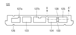
도2는 본 발명의 일 실시예에 따른 배터리 팩을 구성하는 보호회로모듈의 저면도이다.
도 3은 도 2a의 A-A’선 단면도이다.1A is a perspective view of a battery pack according to an embodiment of the present invention.
1B is an exploded perspective view of a battery pack according to an embodiment of the present invention.
2 is a bottom view of a protection circuit module constituting a battery pack according to an exemplary embodiment of the present invention.
3 is a cross-sectional view taken along the line AA ′ of FIG. 2A.
이하에서 실시예와 첨부한 도면을 통하여 본 발명의 배터리 팩에 대하여 보다 구체적으로 설명한다.Hereinafter, the battery pack of the present invention will be described in more detail with reference to the accompanying drawings.
도1a는 본 발명의 일실시예에 따른 배터리 팩의 사시도이고, 도 1b는 본 발명의 일실시예에 따른 배터리 팩의 분해 사시도이고, 도 2는 본 발명의 일 실시예에 따른 배터리 팩을 구성하는 보호회로모듈의 저면도이고, 도 3은 도 2의 A-A’선 단면도이다.1A is a perspective view of a battery pack according to an embodiment of the present invention, FIG. 1B is an exploded perspective view of a battery pack according to an embodiment of the present invention, and FIG. 2 is a battery pack according to an embodiment of the present invention. 3 is a cross-sectional view taken along line AA ′ of FIG. 2.
도 1a내지 도 3을 참조하면, 본 발명의 일 실시예에 따른 배터리 팩(100)은 배터리 셀(110), 보호회로모듈(120), 열전달부재(130), 프레임케이스(140), 커버(150), 및 라벨(160)을 포함하여 이루어 질 수 있다.1A to 3, a
상기 배터리 셀(110)은 각형, 원통형 및 파우치형 등으로 구분된다. 본 발명의 일 실시예에서는 파우치형인 것을 예로 든다. 그러나, 이로써 본 발명이 한정되지 않는다.The
상기 배터리 셀(110)은 양극, 음극 및 양극과 음극 사이에 개재되는 세퍼레이터를 포함하는 전극 조립체(미도시)와, 상기 전극 조립체를 수용하는 파우치 케이스(111), 상기 전극 조립체의 양극 및 음극 각각에 연결되며 상기 파우치 케이스의 외부로 돌출되는 셀 탭(112, 113)을 포함한다. 상기 전극 조립체는 액체, 또는 겔 상태의 전해액을 포함 할 수 있다. 또한 상기 파우치 케이스(111)에 접촉하는 셀탭(112, 113)에는 전기적인 단락을 방지하기 위해 절연테이프(114, 115)가 더 형성 될 수 있다. 그러나, 상기 절연테이프(114, 115)가 모든 실시예에서 사용될 필요는 없다. 또한, 상기 셀탭(112, 113)은 파우치 케이스(111)의 외측으로 연장 및 절곡 되어 보호회로모듈(120)에 연결될 수 있다. The
이러한 배터리 셀(110)은 보호회로모듈(120)이 배치되는 상측부(110a), 상측부(110a)와 연결되는 한쌍의 단측부(110b, 110c)와 한쌍의 장측부(110d, 110e), 및 상측부(110a)와 마주보며 측부들(110b, 110c, 110d, 110e)과 연결되는 하측부(110f)를 포함한다. 여기서, 한 쌍의 단측부(110b, 110c)는 배터리 셀(110)의 상측부(110a)와 연결되는 측부들(110b, 110c, 110d, 110e) 중 폭이 좁은 측부들이며, 한 쌍의 장측부(110d, 110e)는 배터리 셀(110)의 측부들(110b, 110c, 110d, 110e) 중 폭이 넓은 측부들이다.The
상기 보호회로모듈(120)은 배터리 셀(110)의 상측부(110a)에 배치되고, 배터리 셀(110)과 전기적으로 연결되어 배터리 셀(110)의 충ㆍ방전을 제어한다. The
도 2 내지 도 3을 참조하면, 보호회로모듈(120)은 회로 기판(121), 외부 단자들(122), 내부 단자들(123, 124), 양성온도소자(PTC)(125), 체결홈(126) 및 배선패턴(128)을 포함한다.2 to 3, the
상기 회로기판(121)은 판상의 절연층(121a)과 상시 절연층의 표면에 형성된 배선들(미도시) 및 상기 배선을 덮는 보호층(121b)으로 형성될 수 있다. The
상기 회로기판(121)의 하면에는 배터리 셀(100)의 충전 전압, 방전 전압 및 전류를 감지하는 회로(127a), 과충전 전압, 과방전 전압 또는 과전류시에 전류를 차단하는 스위치(127b) 등이 형성될 수 있다.The lower surface of the
상기 외부 단자들(122)은 회로 기판(121)의 상면에 설치되며, 보호 회로 모듈(120)과 외부 장치(미도시)를 전기적으로 연결하는 역할을 한다. The
상기 내부 단자들(123, 124)은 회로기판(121)의 하면에 위치하고, 배터리 셀(100)을 향하도록 형성된다. 상기 내부 단자들(123, 124)은 배터리 셀의 셀탭(112, 113)과 직접 용접에 의해 전기적으로 연결된다. 여기서 제 1 내부 단자(123)와 셀탭(112)은 보호회로모듈(120)의 양극 배선(미도시)과 전기적으로 연결될 수 있으며, 제 2 내부 단자(124)와 셀탭(113)은 양성온도소자(125)를 경유하여 보호회로모듈(120)의 음극 배선 패턴(미도시)과 연결될 수 있다. 더하여 이하의 설명에서는 보다 정확한 설명을 위해 상기 내부 단자들(123, 124)을 제 1 내부단자(123)와 제 2 내부 단자(124)로 명명하여 설명하도록 한다. The
상기 양성온도소자(125)는 상기 회로기판(121)의 하부에 위치하고, 제 2 내부단자(124)와 전기적으로 연결된다.The
상기 양성온도소자(125)는 배터리 셀(110)의 온도가 허용 온도 이상이 되면 전류를 차단시킴으로써 배터리 셀(110)의 발열로 인해 발생되는 이상 현상을 방지하는 역할을 한다. 또한, 상기 양성온도소자(125)는 제 2내부 단자(124)대신 제 1 내부 단자 (123)에 연결 될 수 있다.The
더불어 상기 양성온도소자(125)는 회로기판(121)에 표면 실장이 가능한 칩 PTC(Positive Temperature Coefficient)일 수 있다.In addition, the
또한 상기 양성온도소자(125)는 단자들(125a, 125b)과 기능성소자(125c)로 이루어 질 수 있으며, 일측 단자(125a)가 후술하는 배선패턴(128)과 접촉하고, 타측 단자(125b)가 상기 배선패턴(121c)에 접촉될 수 있다.In addition, the
상기 체결홈(126)은 회로 기판(121)의 장측 외주연에 수개의 홈이 형성된 것으로, 보호회로모듈(120)과 프레임 케이스(130)를 물리적으로 체결하는 역할을 한다.The
상기 배선패턴(128)은 회로기판(121)의 하부에 형성된다. 보다 자세하게는 상기 제 2 내부 단자(124)와 양성온도소자(125) 사이에 위치하며, 배선패턴(128)의 일단과 타단 각각이 제 2 내부 단자(124)와 양성온도소자(125)에 연결된다. 그러므로 상기 배터리 셀(110)로부터 발생하는 전류는 제 2 내부 단자(124), 배선패턴(128), 양성온도소자(125), 패턴(129)을 경유하여 흐른다. 또한 상기 배터리 셀(110)로 부터 발생한 열은 셀탭(113)과 내부단자를 거쳐 상기 배선 패턴(128)을 통해서 양성온도소자(125)로 전달된다.The
상기 열전달 부재(130)는 판상이며 제 2 내부 단자(124)와 양성온도소자(125) 사이에 위치하고, 열전달 부재의 일면이 상기 배선 패턴(128)의 일면과 접촉한다. 상기 열전달 부재(130)의 양 단 각각은 제 2 내부 단자(124) 및 양성온도소자(125)와 접촉된다. 그러므로 상기 배터리 셀(110) 내부로부터 발생된 열은 제 2 내부 단자(124) 및 열전달 부재(130)를 거쳐 양성온도 소자로 전해진다.The
상기 열전달 부재(130)는 전기적으로 절연성이고, 열적으로 도전성인 것이면 어떠한 것을 사용해도 좋다. 예로서 상기 열전달 부재는 (130)는 세라믹 입자와 감압성 아크릴제 및 난연제로 이루어진 열도전성 아크릴 폼 테이프(Thermally Conductive Acrylic Tape)일 수 있고, 또는 솔더크림으로 형성될 수 있다. 또는 상기의 아크릴 폼 테이프 및 솔더크림을 동시에 적용하여 아크릴 폼 테이프와 솔더크림이 적층 형태로 위치하여 열전달 부재(130)를 형성할 수 있다.Any of the
또한 상기 열전달 부재(130)의 폭은 상기 보호회로모듈(120)의 제 2 내부 단자(124)의 폭 및 양성온도 소자(125)의 폭 중 작은 값과 비교해서 적어도 50% 이상이 되도록 형성시키는 것이 바람직하다. 상기 열전달 부재(130)는 열의 이동 통로의 역할을 하는 것이기 때문에 열전달 부재(130)의 폭이 너무 좁게 형성되면 열전달의 효과가 미비할 수 있기 때문이다.In addition, the width of the
상기 배선 패턴(128) 및 열전달달 부재(130)는 제 2 내부 단자(124)와 양성온도 소자(125)사이에 형성됨으로써 베어 셀(110) 내부에서 발생한 열과 양성온도소자(125)에서 감지되는 열의 차이가 크지 않도록 신속한 열전달이 이루어 질 수 있다. 그러므로 상기 배터리 셀(110)의 온도가 고온으로 상승하는 경우에 양성온도소자(125)에 의해 신속한 전류 차단이 이루어질 수 있기 때문에 상기 배터리 팩(100)의 안정성이 향상된다. The
더하여, 상기 열전달 부재(130)가 배터리 셀(110)쪽으로 향하는 면에는 열전달 부재(130)에 전해진 열의 방출을 막기 위해 단열부(미도시)가 더 형성 될 수 있다.In addition, a heat insulating part (not shown) may be further formed on the surface of the
상기 프레임 케이스(140)는 상기 배터리 셀(110)을 감싸며, 보호회로모듈(120)과 물리적으로 결합된다. 이러한 프레임 케이스(140)는 배터리 셀(110)의 상측부(110a)와, 하측부(110f)와, 한쌍의 단측부(110b, 110c)를 각각 커버하되, 배터리 셀(110)중 한쌍의 장측부(110d, 110e)가 외부로 노출되도록 하면서 한쌍의 장측부(110d, 110e)의 측면 모서리부는 덮어지도록 한다. 이러한 구성에 의해 프레임 케이스(140)는 배터리 셀(110)의 수용 공간 (S1)을 갖는다.The
구체적으로, 상기 프레임 케이스(140)는 배터리 셀(110)의 상측부(110a), 한쌍의 단측부(110b, 110c) 및 하측부(110f)를 커버하는 평면부(141, 142, 143, 144)와, 배터리 셀(110)중 한 쌍의 장측부(110d, 110e)의 모서리부를 커버하도록 상기 모서리부와 평행한 평면부(141, 142, 143, 144)의 단부로부터 절곡되어 배터리 셀(110)중 한쌍의 장측부(110d, 110e)를 향해 연장된 연장부(141a, 142a, 143a, 144a)를 포함한다.Specifically, the
또한, 상기 프레임 케이스(140)는 평면부(141)에 형성되는 지지부(145), 체결 돌기(146) 및 리브(147)를 포함할 수 있다. In addition, the
상기 지지부(145)는 사각판의 형태로 평면부(141)의 가장 자리 및 중간 영역에서 보호회로모듈(120)쪽으로 돌출된다. 상기 지지부(145)는 보호회로모듈(120)이 평면부(141)의 상부에 배치될 때 보호회로모듈(120)을 지지하는 역할을 하며, 상기 평면부(141)와 보호회로모듈(120) 사이에 셀탭들(112, 113), 내부 단자들(123, 124) 및 양성온도소자(125)가 배치될 공간을 제공하는 역할을 한다.The
상기 체결 돌기(146)는 원기둥 형태로 보호회로모듈(120)의 체결홈(126)에 대응되는 지지부(145)로부터 보호회로모듈(120)쪽으로 돌출된다. 상기 체결 돌기(146)는 체결홈(126)에 끼워져 보호회로모듈(120)과 프레임 케이스(140)를 물리적으로 체결한다.The
상기 리브(147)는 사각 판의 형태로 지지부(145)의 측부에 돌출된다. 이러한 리브(147)는 후술되는 커버(150)의 리브 결합홀(157)에 끼워져, 프레임 케이스(140)와 커버(150)를 물리적으로 체결하는 역할을 한다.The
상기와 같은 구성을 갖는 프레임 케이스(140)는 사출 성형 공정에 의해 일체로 형성될 수 있으며, PC(Polycarbonate), PETG(Polyethylene Terephthalate Glycol), PE(PolyEthylene), PP(PolyPropylene), 및 ABS(Acronitrile ? Butadiene - Styren) 중 선택된 어느 하나로 형성될 수 있다.The
상기 커버(150)는 배터리 셀(110)의 상측에 결합되며, 내부 공간에 보호회로모듈(120)을 수용한다. 이러한 커버(150)는 커버 플레이트(151)와, 커버 플레이트(151)로부터 보호회로모듈(120)쪽으로 연장된 측벽(152)을 포함한다. The
상기 커버 플레이트(151)는 회로 기판(121)과 대략 유사한 형상으로 형성될 수 있다. 상기 커버 플레이트(151)의 내면은 회로 기판(121)의 상면과 마주 접한다. 커버 플레이트(151)는 외부 단자들(122)과 대응하는 영역에 관통홀(153)이 형성된다. 이러한 관통홀(153)은 외부 단자들(122)을 외부로 노출시켜, 배터리 팩(100)과 외부 장치(미도시)가 전기적으로 연결되도록 한다.The
상기 측벽(152)은 커버(140)의 길이방향 양 끝단에 위치하는 양단부들(154, 155)과, 단부(154)와 단부(155)를 연결하는 연결부들(156)을 포함한다. 여기서, 양단부들(154, 155)과 연결부들(156)의 일부는 후술되는 라벨(160)에 의해 커버된다. The
또한, 측벽(152)은 연결부(156) 중 프레임 케이스(140)의 리브(147)와 대응되는 영역에 형성되는 리브 결합홀(157)을 포함할 수 있다. 이러한 리브 결합홀(157)은 프레임 케이스(140)의 리브(147)가 끼워져, 프레임 케이스(140)와 커버(150)을 물리적으로 체결하는 역할을 한다. In addition, the
상기 라벨(160)은 배터리 셀(110)의 측부들(110b, 110c, 110d, 110e)을 감싸도록 부착된다. 라벨(160)은 커버(150)의 양단부(154, 155)의 일부와 연결부(156)들의 일부를 덮는다. 이러한 라벨(160)은 배터리 셀(110), 프레임 케이스(140) 및 커버(150)의 결합력을 높이는 역할을 한다.
The
본 발명은 상기 실시예들에 한정되지 않고 본 발명의 기술적 요지를 벗어나지 아니하는 범위 내에서 다양하게 수정?변형되어 실시 될 수 있음은 본 발명이 속하는 기술분야에서 통상의 지식을 가진 자에 있어서 자명한 것이다.
It will be apparent to those skilled in the art that the present invention is not limited to the above embodiments and may be variously modified and modified without departing from the technical spirit of the present invention. It is.
100 : 배터리 팩 110 : 배터리 셀
120 : 보호회로모듈 130 : 열전달부재
140 : 프레임케이스 150 : 커버
160 : 라벨100: battery pack 110: battery cell
120: protection circuit module 130: heat transfer member
140: frame case 150: cover
160: label
Claims (8)
상기 셀탭과 연결되는 내부단자, 상기 내부단자와 연결되는 양성온도소자(PTC), 상기 내부단자와 양성온도소자 사이에 위치하며 상기 내부단자 및 양성온도소자를 전기적으로 연결하는 배선패턴을 포함하는 보호회로모듈;
상기 배선패턴과 일면이 접하고, 양 측이 상기 내부단자 및 양성온도소자와 연결되는 열전달 부재를 포함하는 것을 특징으로 하는 배터리 팩. A battery cell having a cell tab;
A protection pattern including an internal terminal connected to the cell tab, a positive temperature device (PTC) connected to the internal terminal, a wiring pattern positioned between the internal terminal and the positive temperature device and electrically connecting the internal terminal and the positive temperature device; Circuit module;
And a heat transfer member having one surface in contact with the wiring pattern and both sides connected to the internal terminal and the positive temperature device.
상기 배터리 셀은 파우치형인 것을 특징으로 하는 배터리 팩.The method of claim 1,
And the battery cell is a pouch type.
상기 연전달 부재는 열도전성 아크릴 폼 테이프로 형성되는 것을 특징으로 하는 배터리 팩.The method of claim 1,
The transfer member is a battery pack, characterized in that formed of a thermally conductive acrylic foam tape.
상기 열도전성 아크릴 폼 테이프는 세라믹 입자들, 감압성 아크릴제 및 난연제를 포함하는 것을 특징으로 하는 배터리 팩.The method of claim 3, wherein
The thermally conductive acrylic foam tape comprises ceramic particles, pressure sensitive acrylic and flame retardant.
상기 열전달 부재는 솔더크림으로 형성되는 것을 특징으로 하는 배터리 팩.The method of claim 1,
The heat transfer member is a battery pack, characterized in that formed with a solder cream.
상기 열전달 부재는 열도전성 아크릴 폼 테이프 및 솔더크림이 적층되어 형성되는 것을 특징으로 하는 배터리 팩.The method of claim 1,
The heat transfer member is a battery pack, characterized in that the thermal conductive acrylic foam tape and the solder cream is formed by stacking.
상기 열전달 부재의 폭은 상기 내부단자 또는 상기 양성온도소자(PTC) 의 폭 중 작은 폭의 적어도 50%인 것을 특징으로 하는 배터리 팩.The method of claim 1,
The width of the heat transfer member is a battery pack, characterized in that at least 50% of the smaller of the width of the internal terminal or the positive temperature element (PTC).
상기 양성온도소자(PTC)는 상기 보호회로모듈의 표면에 실장되는 칩(Chip) PTC인 것을 특징으로 하는 배터리 팩.The method of claim 1,
The positive temperature device (PTC) is a battery pack, characterized in that the chip (Chip) PTC mounted on the surface of the protective circuit module.
Priority Applications (2)
| Application Number | Priority Date | Filing Date | Title |
|---|---|---|---|
| KR1020100107792A KR101192042B1 (en) | 2010-11-01 | 2010-11-01 | Battery Pack |
| US13/052,960 US8854783B2 (en) | 2010-11-01 | 2011-03-21 | Battery pack |
Applications Claiming Priority (1)
| Application Number | Priority Date | Filing Date | Title |
|---|---|---|---|
| KR1020100107792A KR101192042B1 (en) | 2010-11-01 | 2010-11-01 | Battery Pack |
Publications (2)
| Publication Number | Publication Date |
|---|---|
| KR20120061004A true KR20120061004A (en) | 2012-06-12 |
| KR101192042B1 KR101192042B1 (en) | 2012-10-17 |
Family
ID=45996494
Family Applications (1)
| Application Number | Title | Priority Date | Filing Date |
|---|---|---|---|
| KR1020100107792A KR101192042B1 (en) | 2010-11-01 | 2010-11-01 | Battery Pack |
Country Status (2)
| Country | Link |
|---|---|
| US (1) | US8854783B2 (en) |
| KR (1) | KR101192042B1 (en) |
Cited By (2)
| Publication number | Priority date | Publication date | Assignee | Title |
|---|---|---|---|---|
| WO2018221836A1 (en) * | 2017-05-29 | 2018-12-06 | 주식회사 엘지화학 | Battery pack and manufacturing method therefor |
| US11480474B2 (en) | 2018-06-14 | 2022-10-25 | Lg Energy Solution, Ltd. | Apparatus and method for measuring temperature of battery |
Families Citing this family (10)
| Publication number | Priority date | Publication date | Assignee | Title |
|---|---|---|---|---|
| WO2013125748A1 (en) * | 2012-02-23 | 2013-08-29 | 세방전지(주) | Battery cell casing using engraved structure |
| USD687777S1 (en) * | 2012-05-24 | 2013-08-13 | Sony Corporation | Rechargeable battery |
| USD740226S1 (en) * | 2014-01-30 | 2015-10-06 | Nikon Corporation | Battery |
| USD740752S1 (en) * | 2014-01-30 | 2015-10-13 | Nikon Corporation | Battery |
| KR101493829B1 (en) * | 2014-03-27 | 2015-02-16 | 삼성에스디아이 주식회사 | Battery Pack |
| CN105264689B (en) | 2014-04-30 | 2017-11-17 | 株式会社Lg 化学 | Circuit board for secondary cell and the battery pack including the circuit board |
| USD782410S1 (en) * | 2015-12-11 | 2017-03-28 | Hongfujin Precision Electronics (Chongqing) Co. Ltd | Portable power supply |
| KR102357835B1 (en) * | 2017-01-26 | 2022-02-04 | 삼성에스디아이 주식회사 | Battery pack |
| CN112886104B (en) * | 2021-02-10 | 2023-02-03 | 东莞新能德科技有限公司 | Battery and electric equipment |
| DE102022103705A1 (en) | 2022-02-17 | 2023-08-17 | Dr. Ing. H.C. F. Porsche Aktiengesellschaft | battery cell |
Family Cites Families (15)
| Publication number | Priority date | Publication date | Assignee | Title |
|---|---|---|---|---|
| US3345568A (en) * | 1964-01-13 | 1967-10-03 | Motorola Inc | Transistorized portable radio transmitter-receiver structure |
| US5473511A (en) * | 1994-05-05 | 1995-12-05 | Ford Motor Company | Printed circuit board with high heat dissipation |
| JPH1154110A (en) * | 1997-07-31 | 1999-02-26 | N Ii C Mori Energ Kk | Battery protective device having positive characteristic temperature element |
| US6178628B1 (en) * | 1997-10-22 | 2001-01-30 | Aavid Thermalloy, Llc | Apparatus and method for direct attachment of heat sink to surface mount |
| KR100390971B1 (en) * | 1999-05-14 | 2003-07-12 | 미쓰비시덴키 가부시키가이샤 | Flat battery and electronic device |
| EP1071147A1 (en) * | 1999-07-19 | 2001-01-24 | Toshiba Battery Co., Ltd. | Battery pack |
| JP4904614B2 (en) | 2000-06-22 | 2012-03-28 | パナソニック株式会社 | Battery pack and manufacturing method thereof |
| JP2002124305A (en) | 2000-10-13 | 2002-04-26 | Matsushita Electric Ind Co Ltd | Battery pack |
| JP3929839B2 (en) * | 2001-06-28 | 2007-06-13 | 松下電器産業株式会社 | Batteries and battery packs |
| KR100502354B1 (en) | 2003-06-20 | 2005-07-21 | 삼성에스디아이 주식회사 | Pouched-type lithium secondary battery |
| JP3922281B2 (en) * | 2003-11-14 | 2007-05-30 | ソニー株式会社 | Battery pack and battery pack manufacturing method |
| KR20060126838A (en) | 2004-03-09 | 2006-12-08 | 헨켈 코포레이션 | Thermally conductive two-part adhesive composition |
| KR100760784B1 (en) | 2006-07-04 | 2007-09-20 | 삼성에스디아이 주식회사 | Protective circuit module for secondary battery and battery pack using it |
| DE102008010838A1 (en) * | 2008-02-23 | 2009-08-27 | Daimler Ag | Battery with a battery housing and a heat-conducting plate for tempering the battery |
| KR101023874B1 (en) | 2008-10-22 | 2011-03-22 | 삼성에스디아이 주식회사 | Protective circuit module and rechargeable battery including protective circuit module |
-
2010
- 2010-11-01 KR KR1020100107792A patent/KR101192042B1/en not_active IP Right Cessation
-
2011
- 2011-03-21 US US13/052,960 patent/US8854783B2/en not_active Expired - Fee Related
Cited By (5)
| Publication number | Priority date | Publication date | Assignee | Title |
|---|---|---|---|---|
| WO2018221836A1 (en) * | 2017-05-29 | 2018-12-06 | 주식회사 엘지화학 | Battery pack and manufacturing method therefor |
| KR20180130305A (en) * | 2017-05-29 | 2018-12-07 | 주식회사 엘지화학 | Battery pack and method for manufacturing the same |
| CN110546808A (en) * | 2017-05-29 | 2019-12-06 | 株式会社Lg化学 | Battery pack and method for manufacturing same |
| US11355825B2 (en) | 2017-05-29 | 2022-06-07 | Lg Energy Solution, Ltd. | Battery pack and manufacturing method therefor |
| US11480474B2 (en) | 2018-06-14 | 2022-10-25 | Lg Energy Solution, Ltd. | Apparatus and method for measuring temperature of battery |
Also Published As
| Publication number | Publication date |
|---|---|
| KR101192042B1 (en) | 2012-10-17 |
| US8854783B2 (en) | 2014-10-07 |
| US20120106015A1 (en) | 2012-05-03 |
Similar Documents
| Publication | Publication Date | Title |
|---|---|---|
| KR101192042B1 (en) | Battery Pack | |
| KR102152364B1 (en) | Battery pack | |
| US8916278B2 (en) | Heat transfer member for battery pack | |
| EP2375471B1 (en) | Spacer for battery pack and a battery pack comprising the same | |
| EP2835846A1 (en) | Battery pack | |
| KR101261769B1 (en) | Battery pack | |
| KR101502901B1 (en) | Battery pack | |
| US8841011B2 (en) | Secondary battery | |
| US8668996B2 (en) | Battery pack | |
| US9099726B2 (en) | Secondary battery and method of fabricating the same | |
| EP2706588B1 (en) | Lead tab, battery pack having the lead tab and method of manufacturing the lead tab | |
| US11271275B2 (en) | Battery pack | |
| TW201340157A (en) | Switching board of novel structure, and battery module containing the same | |
| KR101397025B1 (en) | Lead tab assembly and battery module with the same | |
| JP2011119203A (en) | Battery pack | |
| JP2005317460A (en) | Battery pack | |
| KR20140096197A (en) | Battery pack | |
| KR20120029168A (en) | Battery pack | |
| JP2005317459A (en) | Battery pack | |
| JP2005317458A (en) | Battery pack | |
| KR20130051399A (en) | Battery pack | |
| KR101985836B1 (en) | Battery pack | |
| KR20200015246A (en) | Battery module | |
| KR20130005117A (en) | Battery cell and battery pack comprising thereof | |
| KR20150037678A (en) | Battery pack |
Legal Events
| Date | Code | Title | Description |
|---|---|---|---|
| A201 | Request for examination | ||
| E902 | Notification of reason for refusal | ||
| E701 | Decision to grant or registration of patent right | ||
| GRNT | Written decision to grant | ||
| FPAY | Annual fee payment |
Payment date: 20150925 Year of fee payment: 4 |
|
| LAPS | Lapse due to unpaid annual fee |