WO2023119924A1 - 電動機及び電動送風機 - Google Patents
電動機及び電動送風機 Download PDFInfo
- Publication number
- WO2023119924A1 WO2023119924A1 PCT/JP2022/041738 JP2022041738W WO2023119924A1 WO 2023119924 A1 WO2023119924 A1 WO 2023119924A1 JP 2022041738 W JP2022041738 W JP 2022041738W WO 2023119924 A1 WO2023119924 A1 WO 2023119924A1
- Authority
- WO
- WIPO (PCT)
- Prior art keywords
- brush
- spring
- electric motor
- commutator
- rotating shaft
- Prior art date
- Legal status (The legal status is an assumption and is not a legal conclusion. Google has not performed a legal analysis and makes no representation as to the accuracy of the status listed.)
- Ceased
Links
Images







Classifications
-
- H—ELECTRICITY
- H02—GENERATION; CONVERSION OR DISTRIBUTION OF ELECTRIC POWER
- H02K—DYNAMO-ELECTRIC MACHINES
- H02K13/00—Structural associations of current collectors with motors or generators, e.g. brush mounting plates or connections to windings; Disposition of current collectors in motors or generators; Arrangements for improving commutation
-
- H—ELECTRICITY
- H02—GENERATION; CONVERSION OR DISTRIBUTION OF ELECTRIC POWER
- H02K—DYNAMO-ELECTRIC MACHINES
- H02K23/00—DC commutator motors or generators having mechanical commutator; Universal AC/DC commutator motors
Definitions
- the present disclosure relates to an electric motor and an electric blower including the electric motor.
- Electric motors are widely used not only in the field of household electric appliances such as vacuum cleaners, but also in the field of electrical components such as automobiles.
- an electric blower mounted on a vacuum cleaner uses an electric motor to rotate a rotating fan.
- Electric motors are used in two-wheeled or four-wheeled vehicles to drive cooling fans such as radiators.
- the brushed electric motor includes a stator, a rotor rotated by the magnetic force of the stator, a commutator attached to the rotating shaft of the rotor, and brushes in sliding contact with the commutator.
- a brushed motor uses a brush spring to press the brush against the commutator.
- the brush spring applies pressure to the brush using spring elasticity.
- coil springs or torsion springs have been used as brush springs for electric motors with brushes.
- the causes of brush wear are classified into two: electrical wear caused by commutation sparks and mechanical wear caused by sliding between the brushes and the commutator. Although it is desirable to reduce both electrical wear and mechanical wear in order to extend the life of the motor, mechanical wear is dominant in motors with small winding current values and commutation sparks. Therefore, it is required to reduce the mechanical wear of the brush.
- Patent Document 1 a technique of using a constant force spring as a brush spring for the purpose of reducing the difference between the initial pressure and the final pressure of the brush spring and reducing the mechanical wear of the brush.
- the constant load spring itself has a constant spring load. Therefore, by using a constant force spring as the brush spring of the electric motor, the load applied to the spring does not change with respect to the stroke (that is, as the brush wears), and it is possible to continue applying a uniform pressure to the brush. Conceivable.
- An object of the present disclosure is to provide an electric motor and an electric blower that can improve the life of the electric motor.
- one aspect of the electric motor according to the present disclosure includes a rotor having a rotating shaft extending in an axial direction, a commutator attached to the rotating shaft, and brushes in contact with the commutator. a brush spring for pressing the brush against the commutator; and a brush storage unit for storing the brush and the brush spring.
- a constant force spring having a spiral portion in contact and a fixed portion fixed to the brush housing portion on the other side, wherein the fixed portion and the brush housing portion are arranged in the axial direction before the brush wears.
- h1 be the height of the spiral portion from the reference position where the brush is in contact with
- h2 be the height of the spiral portion from the reference position where the fixed portion and the brush housing portion contact after the brush is worn
- an electric blower includes the electric motor described above and a fan attached to the rotating shaft of the electric motor.
- the life of the electric motor can be improved.
- FIG. 1 is an external perspective view of the electric motor according to the embodiment when viewed obliquely from above.
- FIG. 2 is a cross-sectional view of the electric motor according to the embodiment, taken along a plane passing through the axis of the rotating shaft and passing through the brushes.
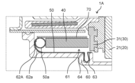
- FIG. 3 is an enlarged view showing the peripheral structure of the brush in the electric motor according to the embodiment.
- FIG. 4 is a perspective view showing the configuration of a brush holder to which various parts are attached in the electric motor according to the embodiment.
- 5 is an exploded perspective view of the various components and brush holder shown in FIG. 4;
- FIG. 6 is an enlarged perspective view showing a configuration of part of the electric motor according to the embodiment.
- FIG. 7A is a diagram showing how the brush is assembled to the brush holder in the electric motor of the comparative example.
- FIG. 7B is a diagram showing how the brush is assembled to the brush holder in the electric motor of the comparative example.
- FIG. 7C is a diagram showing how the brush wears in the electric motor of the comparative example.
- FIG. 7D is a diagram showing how the brush wears in the electric motor of the comparative example.
- FIG. 7E is a diagram showing how the brush wears in the electric motor of the comparative example.
- FIG. 7F is a diagram showing how the brush wears in the electric motor of the comparative example.
- FIG. 8 is a diagram showing a model of a general constant force spring.
- FIG. 9A is a diagram showing how the brush is assembled to the brush holder in the electric motor according to the embodiment.
- FIG. 9B is a diagram showing how the brush is assembled to the brush holder in the electric motor according to the embodiment.
- FIG. 9C is a diagram showing how the brush wears in the electric motor according to the embodiment.
- FIG. 9D is a diagram showing how the brush wears in the electric motor according to the embodiment.
- FIG. 9E is a diagram showing how the brush wears in the electric motor according to the embodiment.
- FIG. 9F is a diagram showing how the brush wears in the electric motor according to the embodiment.
- FIG. 10 is an enlarged view showing the peripheral structure of the brush in the electric motor according to Modification 1.
- FIG. FIG. 10 is an enlarged view showing the peripheral structure of the brush in the electric motor according to Modification 1.
- FIG. 11 is a developed view of a brush spring in an electric motor according to Modification 2.
- FIG. 12 is a developed view of a brush spring in an electric motor according to Modification 3.
- FIG. 13 is a developed view of a brush spring in an electric motor according to Modification 4.
- each figure is a schematic diagram and is not necessarily strictly illustrated.
- the same reference numerals are assigned to substantially the same configurations, and duplicate descriptions are omitted or simplified.
- the terms “upper” and “lower” do not necessarily indicate upward (vertically upward) and downward (vertically downward) directions in absolute spatial recognition.
- FIG. 1 is an external perspective view of an electric motor 1 according to an embodiment when viewed obliquely from above.
- FIG. 2 is a cross-sectional view of the electric motor 1 according to the embodiment taken along a plane passing through the axis C of the rotating shaft 21 and passing through the brushes 40 .
- FIG. 3 is an enlarged view showing a peripheral structure of brushes 40 in electric motor 1 according to the embodiment.
- FIG. 4 is a perspective view showing the configuration of a brush holder 60 to which various parts are attached in the electric motor 1 according to the embodiment.
- FIG. 5 is an exploded perspective view of the various components and brush holder 60 shown in FIG. 3 to 5, the brush 40 shows a state before being worn.
- the electric motor 1 includes a stator 10 (stator) and a rotor 20 (rotor) that rotates due to the magnetic force of the stator 10 .
- the electric motor 1 is a brushed electric motor.
- the electric motor 1 further includes a commutator 30 attached to a rotating shaft 21 of the rotor 20, at least one brush 40 in contact with the commutator 30, a brush spring 50 for pressing the brush 40 against the commutator 30, A brush holder 60 holding the brush 40 and a cover plate 70 covering the brush 40 are provided.
- the electric motor 1 further includes terminals 80 electrically connected to the brushes 40 and capacitors 90 connected to the terminals 80 .
- Electric motor 1 also includes bearing 100 , first bracket 111 , and second bracket 112 .
- electric wires 120 are connected to the electric motor 1 .
- the electric motor 1 is a type of direct current motor (DC motor) driven by direct current.
- a magnet is used as the stator 10 in the electric motor 1 .
- An armature having a coil 22 is used as the rotor 20 in the electric motor 1 .
- the electric motor 1 is a flat-type brushed coreless motor (flat motor) mounted on a two-wheeled or four-wheeled vehicle. Therefore, the stator 10 and rotor 20 do not have a core (iron core). Therefore, the electric motor 1 has a thin and light configuration as a whole.
- the electric motor 1 is a small motor used for a radiator cooling fan in a vehicle.
- the outer diameter (diameter) ⁇ of the electric motor 1 is 120 mm or less. As an example, the outer diameter ⁇ of the electric motor 1 is ⁇ 60 mm, ⁇ 70 mm, ⁇ 90 mm, or the like.
- the electric motor 1 is driven by an input voltage of DC 12V.
- the stator 10 is arranged with a minute air gap between it and the rotor 20 .
- the stator 10 generates magnetic force acting on the rotor 20 .
- the stator 10 is configured to generate magnetic flux on the air gap surface with the rotor 20 .
- the rotor 20 forms a magnetic circuit together with the stator 10, which is an armature.
- the stator 10 as a whole is substantially doughnut-shaped.
- the stator 10 is configured such that N poles and S poles alternately and evenly exist on the air gap surface with the rotor 20 along the circumferential direction of the rotating shaft 21 .
- the stator 10 is a magnetic field that creates magnetic flux for generating torque.
- the stator 10 is composed of a plurality of magnets (magnets).
- the magnets forming the stator 10 are, for example, permanent magnets.
- the direction of the main magnetic flux generated by the stator 10 (magnet) is along the direction in which the rotating shaft 21 extends.
- Stator 10
- the rotor 20 has a rotating shaft 21 and coils 22 .
- Rotor 20 is a coreless rotor that does not have a core.
- the rotor 20 rotates around the direction of the axis C along which the rotating shaft 21 extends (also referred to simply as the "axis direction"). Rotor 20 generates a magnetic force acting on stator 10 .
- the direction of the main magnetic flux generated by the rotor 20 is along the axial center C direction along which the rotating shaft 21 extends.
- the rotor 20 is arranged facing the stator 10 .
- the rotor 20 faces the stator 10 in the axial center C direction along which the rotating shaft 21 extends.
- the coil 22 of the rotor 20 and the stator 10 face each other in the direction of the axis C along which the rotating shaft 21 extends. That is, the coil 22 and the stator 10 are arranged in the direction of the axis C of the rotating shaft 21 .
- the rotating shaft 21 is a shaft having an axis C.
- the rotating shaft 21 is an elongated rod-shaped member.
- the rotating shaft 21 is a metal rod made of a metal material such as SUS (Steel Use Stainless).
- An axis C included in the rotating shaft 21 is the center of rotation when the rotor 20 rotates.
- the longitudinal direction of the rotating shaft 21, that is, the direction in which the rotating shaft 21 extends (stretching direction) is the axial center C direction.
- the rotating shaft 21 is supported by bearings 100 .
- the bearing 100 rotatably supports the rotating shaft 21 .
- the rotating shaft 21 is press-fitted into the bearing 100 .
- Bearing 100 is held by first bracket 111 . Specifically, the bearing 100 is press-fitted into a recess provided in the first bracket 111 and fixed.
- bearing 100 is a ball bearing.
- bearing 100 is a deep groove ball bearing.
- the first end 21a of the rotating shaft 21 is the output-side end (output shaft).
- a first end 21 a of the rotary shaft 21 protrudes from the first bracket 111 and the bearing 100 .
- a first end portion 21 a of the rotating shaft 21 is an end portion of the bearing 100 and the commutator 30 of the rotating shaft 21 on the side of the bearing 100 .
- a load such as a rotating fan is attached to the first end portion 21a.
- the electric motor 1 in which a rotating fan is attached to the rotating shaft 21 can be used as, for example, a cooling fan and an electric blower.
- a second end portion 21b of the rotating shaft 21 is an end portion (counter-output shaft) on the non-output side.
- a second end 21 b of the rotating shaft 21 does not protrude from the second bracket 112 .
- the first bracket 111 and the second bracket 112 are made of metal material, for example.
- the first bracket 111 and the second bracket 112 are made of iron-based material such as cold-rolled steel plate (SPC (Steel Plate Cold) material) or metal such as aluminum.
- a housing is configured by the first bracket 111 and the second bracket 112 .
- a stator 10 and a rotor 20 are arranged in this housing.
- the first bracket 111 is an outer shell member of the electric motor 1. As shown in FIG.
- the first bracket 111 is formed in a bottomed tubular shape having a bottom portion and a cylindrical side wall portion. Magnets forming the stator 10 are fixed to the bottom of the first bracket 111 .
- the coils 22 of the rotor 20 are surrounded by side walls of the first bracket 111 .
- the material of the first bracket 111 and the second bracket 112 is not limited to a metal material, and may be a resin material. From the viewpoint of suppressing noise generated from the electric motor 1, the first bracket 111 and the second bracket 112 are preferably made of a metal material.
- the coils 22 of the rotor 20 are wound coils.
- the rotor 20 has multiple coils 22 .
- the multiple coils 22 are armature windings configured by electric wires.
- the plurality of coils 22 are wound so as to generate magnetic force acting on the stator 10 when current flows.
- the direction of the main magnetic flux generated by each coil 22 is along the axis C along which the rotating shaft 21 extends.
- the plurality of coils 22 are wound flat.
- the coil surface is arranged in a posture facing the axial center C direction along which the rotating shaft 21 extends.
- Each coil 22 is composed of an insulating covered wire having a core wire made of metal such as copper or aluminum and an insulating film covering the core wire.
- the plurality of coils 22 are thin wound coils having coil layers in which the insulated wires are wound in a plane.
- the plurality of coils 22 are configured by, for example, one or a plurality of coil layers in which an insulated wire is wound substantially in a fan shape in a plan view.
- the plurality of coils 22 configured in this way are arranged so as to surround the rotating shaft 21 when viewed from the axial center C direction along which the rotating shaft 21 extends.
- the multiple coils 22 are electrically connected to the commutator 30 . Specifically, the multiple coils 22 are electrically connected to one of the multiple commutator segments 31 of the commutator 30 . Therefore, current flows through the plurality of coils 22 via the commutator segments 31 with which the brushes 40 are in contact.
- a plurality of coils 22 are covered with molding resin 23 . That is, the plurality of coils 22 are resin molded. Therefore, the plurality of coils 22 are integrally molded together with the molding resin 23 by being covered with the molding resin 23 .
- the outer shape of the mold resin 23 after molding the plurality of coils 22 is circular in plan view.
- the mold resin 23 is made of an insulating resin material such as phenol resin or unsaturated polyester (Bulk Molding Compound (BMC)).
- the mold resin 23 may be either thermosetting resin or thermoplastic resin.
- the electric motor 1 is a coreless motor in which the rotor 20 has no core.
- a plurality of thin coils 22 of the rotor 20 are molded with resin. As a result, a thin electric motor 1 with low inductance can be realized.
- the commutator 30 is attached to the rotating shaft 21 . Therefore, the commutator 30 rotates together with the rotating shaft 21 as the rotor 20 rotates.
- the commutator 30 is attached to the second end 21b of the rotating shaft 21 .
- a commutator 30 attached to the rotating shaft 21 may be part of the rotor 20 .
- the commutator 30 has a plurality of commutator pieces 31 (commutator segments) provided along the rotating direction of the rotating shaft 21 .
- the plurality of commutator segments 31 are annularly arranged along the rotation direction of the rotation shaft 21 so as to surround the rotation shaft 21 .
- Each commutator piece 31 is an elongated member extending in the longitudinal direction of the rotating shaft 21 .
- the plurality of commutator segments 31 are conductive terminals made of a metal material such as copper.
- the multiple commutator segments 31 are electrically connected to the coils 22 of the rotor 20 .
- the plurality of commutator segments 31 are arranged insulated from each other. However, the multiple commutator segments 31 are electrically connected by the coils 22 of the rotor 20 .
- the commutator 30 is a molded commutator.
- the commutator 30 has a configuration in which a plurality of commutator segments 31 are molded with molding resin. In this case, the plurality of commutator segments 31 are embedded in the mold resin 23 so that their surfaces are exposed.
- the mold resin 23 is the commutator main body. Mold resin 23 is a substantially cylindrical member having a through hole into which rotating shaft 21 is inserted.
- the mold resin 23 is, for example, a resin molded body made of an insulating resin material such as a thermosetting resin.
- At least one brush 40 is in contact with the commutator 30 .
- the tip of the brush 40 is in contact with the commutator piece 31 of the commutator 30 . Since the commutator 30 rotates as the rotating shaft 21 rotates, the brush 40 keeps contacting all the commutator segments 31 sequentially.
- the brush 40 is a power supply brush for supplying power to the coil 22. Specifically, the brush 40 supplies power to the coil 22 by contacting the commutator segments 31 of the commutator 30 .
- the brush 40 is connected to a terminal 80 fixed to the brush holder 60 by a pigtail wire. When the brushes 40 come into contact with the commutator segments 31 , the armature current supplied from the terminals 80 to the brushes 40 flows through the coils 22 via the commutator segments 31 .
- the brush 40 is a conductive carbon brush made of carbon.
- the brush 40 is an elongated substantially rectangular parallelepiped.
- the brush 40 is preferably a carbon brush containing metal such as copper.
- the brush 40 can be produced, for example, by pulverizing a kneaded product obtained by kneading graphite powder, copper powder, a binder resin, and a curing agent, compressing and molding the crushed product into a rectangular parallelepiped, and firing the crushed product.
- a plurality of brushes 40 are provided.
- the electric motor 1 is provided with two brushes 40 .
- the two brushes 40 are arranged at 180° intervals along the rotation direction of the rotor 20 . That is, the angle formed by the longitudinal directions of the two brushes 40 is 180°.
- the angle formed by the two brushes 40 may not be 180°, and may be 90° such as 60°. It may be below.
- the brush spring 50 is held by a fixing portion 63 formed inside the brush housing portion 61 .
- the brush spring 50 is held at an appropriate position in the brush housing portion 61 .
- a fixing portion 63 is formed on the side of the brush housing portion 61 opposite to the output shaft in the direction in which the axis C extends. The brush spring 50 is held in the brush housing portion 61 by partially inserting the brush spring 50 into the fixing portion 63 .
- the brushes 40 are always in contact with the commutator segments 31 of the commutator 30 under pressure from the brush springs 50 . That is, the brushes 40 are pressed against the commutator 30 by the brush springs 50 . In this manner, the brushes 40 receive the pressing force from the brush springs 50 and come into sliding contact with the commutator 30 .
- the brush 40 is arranged so as to be movable in a direction (radial direction) intersecting with the axial center C direction along which the rotating shaft 21 extends due to wear with the commutator 30 .
- the brush springs 50 are provided according to the number of brushes 40. Since the electric motor 1 is provided with two brushes 40, two brush springs 50 are also provided.
- the brush 40 and brush spring 50 are housed in a brush holder 60 and covered with a cover plate 70 .
- the brush spring 50 applies pressure (spring pressure) to the brush 40 by spring elastic force (spring restoring force) to urge the brush 40 toward the commutator 30 .
- spring pressure spring pressure
- spring elastic force spring restoring force
- the pressing force from the brush springs 50 moves the direction in which the axis C of the rotating shaft 21 is positioned (radial direction), in other words, the axis of the rotating shaft 21 . It moves in a direction perpendicular to the direction in which the center C extends and in the direction in which the axis C is positioned.
- the brush spring 50 is a constant force spring. Therefore, the brush spring 50 applies a uniform load to the brush 40 . That is, the brush spring 50, which is a constant force spring, applies a uniform pressing force to the brush 40. As shown in FIG.
- the brush spring 50 which is a constant load spring, is made of a strip-shaped wire rod.
- the brush spring 50 which is a constant force spring, is a spiral spring.
- a brush spring 50 which is a constant force spring, has a spiral portion 50a (coil portion) formed by spirally winding a strip-shaped wire.
- the brush spring 50 which is a constant force spring, is made of, for example, a strip-shaped wire made of a metal material such as a steel plate.
- the brush spring 50 which is a constant force spring, is made of a long strip-shaped metal plate. Therefore, the spiral portion 50a is a portion of the constant force spring in which a long strip-shaped metal plate is spirally wound multiple times only in one direction.
- the brush spring 50 which is a constant force spring, generates a force (spring restoring force) to return to the original spiral state by extending one end of the wire rod from the spiral portion 50a.
- the brush spring 50 presses the brush 40 against the commutator 30 with the spiral portion 50a. Specifically, the brush spring 50 imparts a load to the brush 40 by the spring restoring force of the spiral portion 50 a when the spiral portion 50 a contacts the rear end portion of the brush 40 .
- the load with which the brush springs 50 press the brushes 40 against the commutator 30 is preferably at least 1 time the radial load generated during the rotation of the rotor 20 .
- the brush spring 50 is arranged so that the spiral axis of the spiral portion 50a and the direction of the axis C along which the rotating shaft 21 extends are twisted. In other words, the brush spring 50 is installed such that the spiral portion 50a is placed vertically. A spiral surface (coil surface) of the spiral portion 50 a is parallel to the axis C of the rotating shaft 21 .
- Electric power is supplied to the brushes 40 from an external power supply arranged outside the electric motor 1 via terminals 80 .
- the external power supply is a power supply that exists outside the electric motor 1 .
- the external power supply supplies the electric motor 1 with a predetermined input voltage.
- the external power supply is a DC power supply that supplies the electric motor 1 with an input voltage of DC 12V.
- the terminals 80 receive electric power that energizes the coils 22 of the rotor 20 via the brushes 40 . Specifically, since the external power supply is a DC power supply, the terminal 80 receives a DC voltage as an input voltage.
- the electric motor 1 is provided with two terminals 80 .
- one terminal (first terminal) of the two terminals 80 is the high voltage side terminal (positive terminal).
- the other terminal (second terminal) of the two terminals 80 is the low voltage side terminal (minus terminal).
- Two terminals 80 are attached to the brush holder 60 .
- a capacitor 90 for noise reduction is connected to the pair of terminals 80 so as to be connected in parallel. Specifically, one lead of the capacitor 90 is connected to one of the pair of terminals 80 . The other lead of capacitor 90 is connected to the other of the pair of terminals 80 . Two capacitors 90 are connected in parallel to the pair of terminals 80 .
- a wire 120 is connected to the terminal 80 .
- Terminal 80 receives power from an external power source via wire 120 .
- the electric wire 120 is a power supply line for supplying power to the terminal 80 .
- the electric wire 120 is a harness.
- the electric wire 120 is connected to each of the two terminals 80 . That is, two electric wires 120 are connected to the electric motor 1 .
- the wire 120 connected to the terminal 80 which is the high-voltage side terminal, is the high-voltage side feeder line (positive side wiring).
- the wire 120 connected to the terminal 80 which is the low-voltage side terminal, is the low-voltage side feeder line (negative side wiring).
- Each electric wire 120 is an insulated wire such as a vinyl wire, and has a core wire made of a conductor such as copper and an insulating coating covering the core wire.
- the brush 40 and the terminal 80 are connected by a pigtail wire. Specifically, one end of the pigtail wire is connected to the brush 40 . The other end of the pigtail wire is connected to terminal 80 . Electric power is supplied from an external power supply to the terminal 80 via the electric wire 120 , thereby supplying current to the brush 40 via the pigtail connected to the terminal 80 .
- the current supplied to the brushes 40 flows through the coils 22 via the commutator segments 31 of the commutator 30 as armature current (driving current).
- armature current driving current
- magnetic flux is generated in the rotor 20 (coil 22).
- the magnetic force generated by the interaction between the magnetic flux generated in the rotor 20 and the magnetic flux generated from the stator 10 becomes torque for rotating the rotor 20 .
- the direction in which the current flows is switched depending on the positional relationship when the commutator segments 31 of the commutator 30 and the brushes 40 are in contact with each other.
- FIG. 6 is an enlarged perspective view showing a configuration of part of the electric motor 1 according to the embodiment.
- the brush holder 60 is a holding member that holds the brush 40 . As shown in FIG. 2, the brush holder 60 is also a shell member forming the shell of the electric motor 1 and covers the second bracket 112 from the outside.
- the brush holder 60 is made of, for example, an insulating resin material.
- the brush holder 60 is a resin molded product formed by integral molding using a resin material.
- the resin material forming the brush holder 60 is phenol resin, but is not limited to this.
- the brush holder 60 has a brush storage portion 61 in which the brush 40 is stored.
- the brush housing portion 61 is a concave portion formed in a concave shape.
- the brush housing portions 61 are formed according to the number of brushes 40 .
- Two brush storage portions 61 are formed in the brush holder 60 .
- Each of the two brush housing portions 61 is elongated in a direction orthogonal to the axis C of the rotating shaft 21 (that is, the radial direction of the rotation of the rotating shaft 21), and has a concave rectangular cross-sectional shape. .
- the brush storage portion 61 stores the brush spring 50 together with the brush 40 . Therefore, the longitudinal length of the brush housing portion 61 is longer than the length of the brush 40 .
- the brush spring 50 is arranged in the brush housing portion 61 so that the spiral portion 50 a is positioned behind the rear end portion of the brush 40 .
- the brush spring 50 is arranged in the brush housing portion 61 so that the spiral portion 50a is positioned on the opposite side of the brush 40 from the side on which the commutator 30 is positioned. In this case, the outer ends of the brush springs 50 are pulled out toward the commutator 30 through below the brushes 40 and fixed to the front bottom of the brush housing 61 .
- a cover plate 70 is provided so as to cover the brushes 40 housed in the brush housing portion 61 .
- the cover plate 70 covers the brushes 40 and the brush springs 50 housed in the brush housing portion 61 .
- the cover plate 70 also has a function of guiding the spiral portion 50a of the brush spring 50 when the spiral portion 50a moves toward the commutator 30 as the brush 40 wears.
- the cover plate 70 is formed with a recessed groove into which the upper portion of the spiral portion 50a is fitted. The spiral portion 50a moves while being guided by this groove.
- the cover plate 70 is made of, for example, a metal plate, and is arranged to cover the brush storage section 61 .
- the brush housing portion 61 has an inclined portion 62.
- the inclined portion 62 is formed on the rear side of the brush 40 in the brush housing portion 61 .
- the inclined portion 62 is formed at the end of the brush housing portion 61 opposite to the side where the commutator 30 is positioned with respect to the brush 40 .
- the inclined portion 62 is formed at the rear end portion of the brush housing portion 61 .
- the inclined portion 62 has an inclined surface 62a. As shown in FIG. 3, in a cross-sectional view, the inclined surface 62a is formed such that its height gradually decreases from the back of the brush housing portion 61 toward the front (toward the rotating shaft 21).
- the inclined surface 62a is a curved surface. As an example, the inclined surface 62a is arcuate in a cross-sectional view.
- the inclined surface 62a of the inclined portion 62 is in contact with the brush spring 50 at least before the brush 40 is worn (initial stage). Specifically, as shown in FIG. 3, the spiral portion 50a of the brush spring 50 is in contact with the inclined surface 62a before the brush 40 is worn. As a result, at least before the brush 40 wears, the spiral portion 50a of the brush spring 50 rides on the inclined surface 62a and is lifted upward (that is, in the direction away from the bottom surface of the brush housing portion 61).
- the height of the spiral portion 50a from the reference position 64 which is the position where the fixed portion 63 and the brush housing portion 61 are in contact in the initial state of the brush 40 (before the brush 40 is worn), is If h1 (see FIG. 9C) and h2 (see FIG. 9F) represent the height of the spiral portion 50a from the reference position 64 where the fixed portion 63 and the brush housing portion 61 are in contact with each other at the final stage of the brush 40, then h1>h2. It satisfies the relational expression of That is, the inclined portion 62 has a structure to satisfy the relational expression h1>h2.
- the reference position 64 may be a starting point other than the position where the fixed portion 63 and the brush housing portion 61 are in contact, as long as the heights h1 and h2 of the spiral portion 50a can be defined.
- the constant load spring itself has a constant spring load. Therefore, it was thought that by using a constant force spring as the brush spring 50 of the electric motor, it would be possible to continue applying a uniform pressure to the brush 40 without changing the spring load with respect to the stroke.
- FIGS. 7A to 7F are diagrams showing how the brush 40 is assembled to the brush holder 60X and how the brush 40 wears in the electric motor of the comparative example.
- “O” indicates the center of the spiral portion 50a of the brush spring 50.
- FIG. "R” indicates the radius of curvature of the outermost peripheral portion of the spiral portion 50a.
- dashed lines indicate the trajectory of the center O of the spiral portion 50a.
- FIG. 7A and 7B show how the brush 40 is stored in the brush storage portion 61 of the brush holder 60X.
- the spiral portion 50a of the brush spring 50 is moved forward (commutator) of the brush housing portion 61 by the restoring force of the spiral portion 50a. 30 side).
- FIG. 7C to 7F show how the brush 40 wears out in the actual use environment of the electric motor of the comparative example.
- FIG. 7C shows the initial state before the brush 40 wears out.
- the commutator 30 rotates and the brushes 40 wear out.
- the brush 40 is in contact with the commutator 30 due to the pressing force of the brush spring 50 . Therefore, when the commutator 30 rotates, friction occurs between the front end surface of the brush 40 and the commutator 30 . Due to this mechanical friction, the brush 40 is worn as shown in FIG. 7C ⁇ FIG. 7D ⁇ FIG. 7E ⁇ FIG. 7F.
- FIG. 7D shows a state in which the brush 40 has worn about 3 mm from the initial state
- FIG. 7E shows a state in which the brush 40 has worn about 8 mm from the initial state
- FIG. 7F shows a state in which the brush 40 is in its final stage (final stage) (a state in which the spring load is zero). The end of the brush 40 is the time when the spring load becomes zero and the contact between the brush 40 and the commutator 30 is lost, causing the circuit to open and the motor to stop operating and reach the end of its life.
- the spring load gradually decreases from the initial state in FIG. 7C, and the constant load region starts from the state in FIG. 7D.
- This constant load region continues from the state of FIG. 7D to the state of FIG. 7E.
- the spring load gradually decreases from the state of FIG. 7E to the final state of FIG. 7F.
- the position (height) of the center O of the spiral portion 50a changes as shown in FIGS. 7C to 7F.
- the spring load is high when the brush 40 is in the initial state. After the spring load changes to become smaller as the brush 40 wears, the spring load becomes constant.
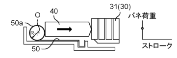
- the inventors of the present application have investigated the cause of the increase in the spring load in the initial stage before and immediately after the brush 40 wears, and found the following. This is because the shape of the spring after the outer peripheral portion of the wire of the spiral portion 50a of the brush spring 50 is stretched (in the initial state of motor assembly) differs from the shape of the spring when the wire is wound back to the spiral portion 50a (state of brush wear). I found out.
- FIG. 8 is a diagram showing a model of a general constant force spring.
- the constant force spring in FIG. 8 has a spiral portion (coil portion) around which a strip-shaped wire rod with a constant width is wound.
- the load P and the stress ⁇ can be obtained by the following (formula 1) and (formula 2).
- P [N] is the load applied to the constant force spring
- E [Mpa] is the modulus of longitudinal elasticity
- b [mm] is the width of the wire
- t [mm] is The plate thickness of the wire
- R n [mm] is the minimum natural radius of the spiral portion
- R o [mm] is the outer radius of the spiral portion
- ⁇ [Mpa] is the bending stress.
- the shape of the spiral portion 50a of the brush spring 50 changes such that the radius of curvature R of the outermost peripheral portion of the spiral portion 50a increases as the brush 40 shifts from the initial state of FIG. 7C to the state of FIG. 7D. . Therefore, it is considered that the spring load of the brush spring 50 becomes smaller. As a result, in the electric motor of the comparative example, the spring load in the state shown in FIG. growing.
- the spring load is higher than the target value in the initial stage, and the curvature radius R of the outermost peripheral portion of the spiral portion 50a of the brush spring 50 changes. It was found that the spring load changed until it stopped.
- the inventors of the present application conducted extensive studies and found that the spring load of the brush spring 50 in the initial stage can be reduced by devising the shape of the spiral portion 50a of the brush spring 50 in the initial state before the brush 40 is worn. I found
- the idea is to provide the inclined portion 62 in the brush housing portion 61 of the brush holder 60. got Specifically, by providing an inclined portion 62 in the brush housing portion 61 and keeping the inclined portion 62 in contact with the spiral portion 50a of the brush spring 50, the spring load of the brush spring 50 in the initial state of the brush 40 is reduced. bottom.
- FIGS. 9A to 9F are diagrams showing how the brushes 40 are assembled to the brush holder 60 and how the brushes 40 wear out in the electric motor 1 according to the embodiment.
- “O” indicates the center of the spiral portion 50a of the brush spring 50
- “R” indicates the radius of curvature of the outermost peripheral portion of the spiral portion 50a.
- the dashed line also indicates the trajectory of the center O of the spiral portion 50a.
- FIGS. 7A and 7B show how the brush 40 is housed in the brush housing portion 61 of the brush holder 60, similarly to FIGS. 7A and 7B. Therefore, in FIG. 9A, similarly to FIG. 7A, when the brush 40 starts to be inserted into the brush housing portion 61, the spiral portion 50a of the brush spring 50 is positioned in front of the brush housing portion 61 (commutator 30 side). there is
- FIGS. 9A and 9B similarly to FIGS. 7A and 7B, when inserting the brush 40 into the brush housing portion 61, the rear end face of the brush 40 is pressed against the spiral portion 50a of the brush spring 50, The brush 40 is moved to the rear side of the brush housing portion 61. - ⁇ As a result, the spiral portion 50 a moves to the rear portion of the brush housing portion 61 and the brush 40 is housed in the brush housing portion 61 .
- the electric motor 1 is provided with an inclined portion 62 at the rear end portion of the brush housing portion 61 .
- the spiral portion 50 a moved to the rear portion of the brush housing portion 61 rides on the inclined surface 62 a of the inclined portion 62 .
- the spiral portion 50a of the brush spring 50 rides on the inclined surface 62a of the inclined portion 62. As shown in FIG. As a result, the shape of the outermost peripheral portion of the spiral portion 50a of the brush spring 50 changes. Specifically, the radius of curvature R of the outermost peripheral portion of the spiral portion 50a increases. As a result, the spring load of the brush spring 50 is smaller in the state of FIG. 9C than in the state of FIG. 7C.
- FIG. 9C shows a state in which the brush 40 has been worn by about 3 mm from the initial state, similar to FIG. 7D.
- FIG. 9E shows a state where the brush 40 has been worn by about 8 mm from the initial state, similar to FIG. 7E.
- FIG. 9F shows a state in which the brush 40 is in the final stage (final stage) (a state in which the spring load is zero), similar to FIG. 7F.
- the radius of curvature R of the outermost peripheral portion of the spiral portion 50a of the brush spring 50 becomes It remains large and does not change. Therefore, the spring load of the brush spring 50 does not change.
- the spring load of the brush spring 50 is constant (that is, constant load region) from the initial stage before the brush 40 wears. Thereafter, the spring load of brush spring 50 decreases towards the end of brush 40 .
- the position (height) of the center O of the spiral portion 50a also changes, as shown in FIGS. 9C to 9F. Specifically, the position (height) of the center O of the spiral portion 50a does not change and is constant from the state of FIG. 9C to the state of FIG. 9E. The position (height) of the center O of the spiral portion 50a gradually decreases from the state of FIG. 9E to the state of FIG. 9F.
- the height of the spiral portion 50a from the reference position 64 where the fixed portion 63 and the brush housing portion 61 are in contact before the brush 40 is worn (that is, 9C) is h1
- the height of the spiral portion 50a from the reference position 64 where the fixed portion 63 and the brush housing portion 61 are in contact at the end of the brush 40 is h2
- the spring load of the brush spring 50 can be reduced in the initial state of FIG. 9C.
- the spring load of the brush spring 50 can be reduced even in the initial stage from the state of FIG. 9C to the state of FIG. 9D.
- the mechanical wear of the brushes 40 can be effectively reduced in the effective wear length of the brushes, so the life of the electric motor 1 can be extended.
- the height of the spiral portion 50a from the reference position 64 where the fixed portion 63 and the brush housing portion 61 are in contact at the final stage of the brush 40 is h2, and the relation h1>h2 is satisfied. configured to satisfy the formula.
- h2 be the height of the spiral portion 50a from the reference position 64 where the fixed portion 63 and the brush housing portion 61 are in contact after the brush 40 is worn (for example, after the state shown in FIG. 9C)
- the relational expression h1>h2 may be configured to satisfy
- the height of the spiral portion 50a (that is, the top of the spiral portion 50a) from the reference position 64 where the fixed portion 63 and the brush housing portion 61 are in contact with each other in the direction of the axis C is used as a reference.
- the heights h1 and h2 of the spiral portion 50a are configured to satisfy the relational expression of h1>h2, the present invention is not limited to this.
- the center O of the spiral portion 50a may be used as a reference.
- P1 is the center position of the spiral portion 50a before the brush 40 is worn
- P2 is the center position of the spiral portion 50a after the brush 40 is worn (for example, the final stage of the brush 40). It may be configured to satisfy the relational expression. Also in this case, the spring load of the brush spring 50 can be reduced in the initial state and the initial stage of the brush 40 .
- the radius of curvature or the curvature of the spiral portion 50a may be used as a reference instead of the height or center position of the spiral portion 50a.
- the radius of curvature of the outermost peripheral portion of the spiral portion 50a before the brush 40 is worn is R1 (or the curvature is r1), and the outermost periphery of the spiral portion 50a after the brush 40 is worn (for example, the final stage of the brush 40).
- It may be configured to satisfy the relational expression P1>P2 (or the relational expression r1 ⁇ r2) with the radius of curvature of the portion being R2 (or the curvature being r2).
- the spring load of the brush spring 50 can be reduced in the initial state and the initial stage of the brush 40 .
- the electric motor 1 of the present embodiment includes the rotor 20 having the rotating shaft 21 extending in the axial direction, the commutator 30 attached to the rotating shaft 21, and the brushes 40 in contact with the commutator 30. , a brush spring 50 for pressing the brush 40 against the commutator 30, and a brush housing portion 61 housing the brush 40 and the brush spring 50.
- the brush spring 50 is a constant force spring having a spiral portion 50a on one side of which a strip-shaped wire is wound and in contact with the brush 40, and a fixed portion 63 fixed to the brush housing portion 61 on the other side.
- the height of the spiral portion 50a from the reference position where the fixed portion 63 and the brush housing portion 61 contact before the brush 40 wears is h1
- the fixed portion 63 and the brush housing after the brush 40 wears Assuming that the height of the spiral portion 50a from the reference position where the portion 61 is in contact is h2, the structure satisfies the relational expression h1>h2.
- This structure is preferably an inclined portion 62 formed in the brush housing portion 61 on the side opposite to the side where the commutator 30 is positioned with respect to the brush 40 .
- the inclined portion 62 has an inclined surface 62a with which the constant force spring contacts at least before the brush 40 wears.
- the rotor 20 is provided with a plurality of thin coils 22 electrically connected to the commutator 30, and the plurality of coils 22 are preferably integrally molded with resin.
- the electric blower includes an electric motor 1 and a fan attached to a rotating shaft 21.
- the inclined surface 62a of the inclined portion 62 provided in the brush housing portion 61 is a curved surface.
- the inclined surface 62a of the inclined portion 62A provided in the brush housing portion 61 may be flat. That is, the inclined surface 62a may be a tapered surface.
- FIG. 10 is an enlarged view showing a peripheral structure of brushes 40 in electric motor 1A according to Modification 1. As shown in FIG.
- the brush housing portion 61 is provided with a structure for satisfying the relational expression h1>h2.
- a structure that satisfies the relational expression h1>h2 may be provided in the wire constituting the brush spring.
- FIG. 11 is a developed view of the brush spring 50A in the electric motor according to Modification 2.
- the plate width b at the tip portion of the wire rod 51 can be reduced in the above (Equation 1). Therefore, the spring load P can be reduced. Therefore, the spring load of the brush spring 50A can be reduced when the brush 40 is in the initial state.
- FIG. 12 is a developed view of a brush spring 50B in an electric motor according to Modification 3. As shown in FIG. Thereby, it is possible to suppress a sudden change in the spring load between the narrow portion 51a and the thick portion 51b.
- the plate width may be narrowed by forming an opening 51d by punching the center of the width at the tip of the wire rod 51 constituting the brush spring 50C.
- FIG. 13 is a developed view of a brush spring 50C in an electric motor according to Modification 4. As shown in FIG. In this case also, the spring load of the brush spring 50 can be reduced when the brush 40 is in the initial state.
- the electric motor 1 has only one bearing 100 .
- the electric motor 1 may be provided with two bearings.
- one of the two bearings can be attached to the first end 21 a of the rotating shaft 21 and the other can be attached to the second end 21 b of the rotating shaft 21 .
- the electric motor 1 is a coreless motor in which the stator 10 and rotor 20 do not have cores.
- the electric motor 1 may be an electric motor in which the stator 10 and the rotor 20 have cores.
- the stator 10 is composed only of permanent magnets. However, it is not limited to this.
- the stator 10 may be a stator composed of permanent magnets and an iron core, or an armature composed of stator windings and an iron core without using permanent magnets.
- the electric motor 1 is a flat motor with an external size smaller than the outer diameter.
- the technology of the present disclosure can also be applied to, for example, a cylindrical electric motor having a cylindrical housing with an outer size whose thickness is greater than its outer diameter.
- the direction of the main magnetic flux generated by the stator 10 and the rotor 20 was the axial center C direction of the rotating shaft 21 .
- the direction of the main magnetic flux generated by the stator 10 and the rotor 20 may be a direction orthogonal to the axial center C direction of the rotating shaft 21 (radial direction of rotation of the rotating shaft 21).
- the technology of the present disclosure can also be applied to an inner rotor type motor in which the rotor 20 is arranged inside the stator 10 .
- the electric motor 1 is a vehicle motor used in a vehicle. However, it is not limited to this.
- the technology of the present disclosure can also be applied to electric motors used in various other electric devices, such as electric motors used in electric blowers and the like mounted on electric vacuum cleaners and the like.
- the technology of the present disclosure can be widely used in various products equipped with electric motors, including products in the field of electric equipment such as automobiles and the field of household electric appliances.
- Reference Signs List 1 1A electric motor 10 stator 20 rotor 21 rotating shaft 21a first end 21b second end 22 coil 23 molded resin 30 commutator 31 commutator piece 40 brush 50, 50A, 50B, 50C brush spring 50a spiral portion 51 wire rod 51a Narrow portion 51b Thick portion 51c Taper portion 51d Opening 60 Brush holder 61 Brush storage portion 62, 62A Inclined portion 62a Inclined surface 63 Fixed portion 64 Reference position 70 Cover plate 80 Terminal 90 Capacitor 100 Bearing 111 First bracket 112 Second 2 bracket 120 electric wire
Landscapes
- Engineering & Computer Science (AREA)
- Power Engineering (AREA)
- Motor Or Generator Current Collectors (AREA)
- Motor Or Generator Frames (AREA)
Priority Applications (2)
| Application Number | Priority Date | Filing Date | Title |
|---|---|---|---|
| JP2023569147A JPWO2023119924A1 (https=) | 2021-12-23 | 2022-11-09 | |
| CN202280080655.7A CN118355592A (zh) | 2021-12-23 | 2022-11-09 | 电动机和电动风机 |
Applications Claiming Priority (2)
| Application Number | Priority Date | Filing Date | Title |
|---|---|---|---|
| JP2021-209754 | 2021-12-23 | ||
| JP2021209754 | 2021-12-23 |
Publications (1)
| Publication Number | Publication Date |
|---|---|
| WO2023119924A1 true WO2023119924A1 (ja) | 2023-06-29 |
Family
ID=86902107
Family Applications (1)
| Application Number | Title | Priority Date | Filing Date |
|---|---|---|---|
| PCT/JP2022/041738 Ceased WO2023119924A1 (ja) | 2021-12-23 | 2022-11-09 | 電動機及び電動送風機 |
Country Status (3)
| Country | Link |
|---|---|
| JP (1) | JPWO2023119924A1 (https=) |
| CN (1) | CN118355592A (https=) |
| WO (1) | WO2023119924A1 (https=) |
Cited By (2)
| Publication number | Priority date | Publication date | Assignee | Title |
|---|---|---|---|---|
| JP7440147B1 (ja) | 2023-08-10 | 2024-02-28 | トライス株式会社 | 回転電機用のブラシモジュール |
| WO2025173389A1 (ja) * | 2024-02-13 | 2025-08-21 | パナソニックIpマネジメント株式会社 | 電動機 |
Citations (3)
| Publication number | Priority date | Publication date | Assignee | Title |
|---|---|---|---|---|
| JPS513002U (https=) * | 1974-06-24 | 1976-01-10 | ||
| JPS5562171U (https=) * | 1978-10-19 | 1980-04-26 | ||
| JPH0677473U (ja) * | 1993-03-30 | 1994-10-28 | 山本電気株式会社 | フラットモータにおけるブラシの保持装置 |
-
2022
- 2022-11-09 JP JP2023569147A patent/JPWO2023119924A1/ja active Pending
- 2022-11-09 WO PCT/JP2022/041738 patent/WO2023119924A1/ja not_active Ceased
- 2022-11-09 CN CN202280080655.7A patent/CN118355592A/zh active Pending
Patent Citations (3)
| Publication number | Priority date | Publication date | Assignee | Title |
|---|---|---|---|---|
| JPS513002U (https=) * | 1974-06-24 | 1976-01-10 | ||
| JPS5562171U (https=) * | 1978-10-19 | 1980-04-26 | ||
| JPH0677473U (ja) * | 1993-03-30 | 1994-10-28 | 山本電気株式会社 | フラットモータにおけるブラシの保持装置 |
Cited By (3)
| Publication number | Priority date | Publication date | Assignee | Title |
|---|---|---|---|---|
| JP7440147B1 (ja) | 2023-08-10 | 2024-02-28 | トライス株式会社 | 回転電機用のブラシモジュール |
| JP2025025687A (ja) * | 2023-08-10 | 2025-02-21 | トライス株式会社 | 回転電機用のブラシモジュール |
| WO2025173389A1 (ja) * | 2024-02-13 | 2025-08-21 | パナソニックIpマネジメント株式会社 | 電動機 |
Also Published As
| Publication number | Publication date |
|---|---|
| CN118355592A (zh) | 2024-07-16 |
| JPWO2023119924A1 (https=) | 2023-06-29 |
Similar Documents
| Publication | Publication Date | Title |
|---|---|---|
| CN101179217B (zh) | 换向器电动机的电刷装置及电动吸尘器 | |
| WO2023119924A1 (ja) | 電動機及び電動送風機 | |
| JP7774225B2 (ja) | 電動機及び電動送風機 | |
| JPWO2023119924A5 (https=) | ||
| WO2023119839A1 (ja) | 電動機及び部品収納箱 | |
| JPWO2023119839A5 (https=) | ||
| EP4270743B1 (en) | Electric motor | |
| WO2022215369A1 (ja) | 電動機及び電動送風機 | |
| JPWO2022215369A5 (https=) | ||
| JP7584051B2 (ja) | 電動機及び電気機器 | |
| WO2022202274A1 (ja) | 電動機及び電動送風機 | |
| JPWO2022202274A5 (https=) | ||
| JPWO2022137890A5 (https=) | ||
| WO2024084849A1 (ja) | 電動機 | |
| WO2024084845A1 (ja) | 電動機 | |
| US20250379498A1 (en) | Electric motor | |
| WO2024084844A1 (ja) | 電動機 | |
| JP7542172B2 (ja) | 電動機 | |
| WO2024236951A1 (ja) | 電源端子及び電動機 | |
| CN121336346A (zh) | 电动机 | |
| US20250300517A1 (en) | Electric motor | |
| WO2025173389A1 (ja) | 電動機 | |
| JP2025114891A (ja) | 電動機 | |
| WO2023248586A1 (ja) | 電動機 | |
| WO2023119801A1 (ja) | 電動機及び端子 |
Legal Events
| Date | Code | Title | Description |
|---|---|---|---|
| 121 | Ep: the epo has been informed by wipo that ep was designated in this application |
Ref document number: 22910643 Country of ref document: EP Kind code of ref document: A1 |
|
| ENP | Entry into the national phase |
Ref document number: 2023569147 Country of ref document: JP Kind code of ref document: A |
|
| WWE | Wipo information: entry into national phase |
Ref document number: 202280080655.7 Country of ref document: CN |
|
| NENP | Non-entry into the national phase |
Ref country code: DE |
|
| 122 | Ep: pct application non-entry in european phase |
Ref document number: 22910643 Country of ref document: EP Kind code of ref document: A1 |