WO2023119897A1 - Probe head - Google Patents
Probe head Download PDFInfo
- Publication number
- WO2023119897A1 WO2023119897A1 PCT/JP2022/040970 JP2022040970W WO2023119897A1 WO 2023119897 A1 WO2023119897 A1 WO 2023119897A1 JP 2022040970 W JP2022040970 W JP 2022040970W WO 2023119897 A1 WO2023119897 A1 WO 2023119897A1
- Authority
- WO
- WIPO (PCT)
- Prior art keywords
- plunger
- hole
- tapered
- horizontal
- probe
- Prior art date
Links
Images


Classifications
-
- G—PHYSICS
- G01—MEASURING; TESTING
- G01R—MEASURING ELECTRIC VARIABLES; MEASURING MAGNETIC VARIABLES
- G01R1/00—Details of instruments or arrangements of the types included in groups G01R5/00 - G01R13/00 and G01R31/00
- G01R1/02—General constructional details
- G01R1/06—Measuring leads; Measuring probes
- G01R1/067—Measuring probes
-
- G—PHYSICS
- G01—MEASURING; TESTING
- G01R—MEASURING ELECTRIC VARIABLES; MEASURING MAGNETIC VARIABLES
- G01R31/00—Arrangements for testing electric properties; Arrangements for locating electric faults; Arrangements for electrical testing characterised by what is being tested not provided for elsewhere
- G01R31/26—Testing of individual semiconductor devices
Landscapes
- Physics & Mathematics (AREA)
- General Physics & Mathematics (AREA)
- Testing Or Measuring Of Semiconductors Or The Like (AREA)
- Testing Of Individual Semiconductor Devices (AREA)
- Measuring Leads Or Probes (AREA)
Abstract
Provided is a probe head comprising a probe and an insulating support in which a tapered hole for supporting a plurality of portions of the probe is provided.
Description
本発明は、プローブヘッドに関する。
The present invention relates to probe heads.
集積回路等の検査対象物を検査するため、プローブヘッドを介して検査対象物を検査基板に電気的に接続することがある。例えば、特許文献1に記載されているように、プローブヘッドは、プローブと、プローブが挿通される貫通孔が設けられた絶縁支持体と、を備えている。プローブは、検査対象物の第1電極に接触する第1プランジャと、検査基板の第2電極に接触する第2プランジャと、スプリングと、を有している。検査対象物の検査では、第2プランジャを検査基板の第2電極に接触させて、スプリングによって第1プランジャを上方に向けて付勢させた後、第1プランジャを検査対象物の第1電極に接触させている。
In order to inspect an inspection target such as an integrated circuit, the inspection target may be electrically connected to the inspection substrate via the probe head. For example, as described in Patent Literature 1, a probe head includes a probe and an insulating support provided with a through hole through which the probe is inserted. The probe has a first plunger that contacts the first electrode of the test object, a second plunger that contacts the second electrode of the test substrate, and a spring. In the inspection of the inspection object, the second plunger is brought into contact with the second electrode of the inspection substrate, the first plunger is urged upward by the spring, and then the first plunger is brought into contact with the first electrode of the inspection object. are in contact.
プローブを絶縁支持体の貫通孔内で摺動させるため、プローブの外側面と、貫通孔の内側面と、の間には隙間が設けられている。検査対象物の検査においては、第2プランジャを検査基板の第2電極に接触させた後、第1プランジャの先端が開放された状態で、第1プランジャが上方に向けて付勢されることがある。第1プランジャの先端が開放された状態においては、第1プランジャの先端から第1プランジャの先端の反対側の基端へ向かう方向の外力が第1プランジャの先端に加わっていない。しかしながら、この場合、第1プランジャが傾いて、第1プランジャの先端の位置精度が悪化することがある。
A gap is provided between the outer surface of the probe and the inner surface of the through hole in order to allow the probe to slide within the through hole of the insulating support. In the inspection of the inspection object, after the second plunger is brought into contact with the second electrode of the inspection substrate, the first plunger may be urged upward while the tip of the first plunger is released. be. In the state where the tip of the first plunger is released, no external force is applied to the tip of the first plunger in the direction from the tip of the first plunger to the base end opposite to the tip of the first plunger. However, in this case, the first plunger may tilt and the positional accuracy of the tip of the first plunger may deteriorate.
本発明の目的の一例は、プローブの先端の位置精度を良好にすることにある。本発明の他の目的は、本明細書の記載から明らかになるであろう。
One example of the purpose of the present invention is to improve the positional accuracy of the tip of the probe. Other objects of the present invention will become clear from the description herein.
本発明の一態様は、
プローブと、
前記プローブの複数の部分を支持するテーパ孔が設けられた絶縁支持体と、
を備えるプローブヘッドである。 One aspect of the present invention is
a probe;
an insulating support provided with tapered holes for supporting a plurality of portions of the probe;
A probe head comprising:
プローブと、
前記プローブの複数の部分を支持するテーパ孔が設けられた絶縁支持体と、
を備えるプローブヘッドである。 One aspect of the present invention is
a probe;
an insulating support provided with tapered holes for supporting a plurality of portions of the probe;
A probe head comprising:
本発明の上記態様によれば、プローブの先端の位置精度を良好にすることができる。
According to the above aspect of the present invention, it is possible to improve the positional accuracy of the tip of the probe.
以下、本発明の実施形態について、図面を用いて説明する。すべての図面において、同様な構成要素には同様の符号を付し、適宜説明を省略する。
Hereinafter, embodiments of the present invention will be described with reference to the drawings. In all the drawings, the same constituent elements are denoted by the same reference numerals, and the description thereof will be omitted as appropriate.
本明細書において、「第1」、「第2」、「第3」等の序数詞は、特に断りのない限り、同様の名称が付された構成を単に区別するために付されたものであり、構成の特定の特徴(例えば、順番又は重要度)を意味するものではない。
In the present specification, ordinal numbers such as "first", "second", "third", etc., unless otherwise specified, are merely used to distinguish similarly named configurations. , does not imply any particular feature (eg, order or importance) of the configurations.
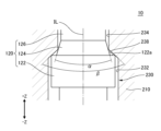
図1は、実施形態に係るプローブヘッド10の断面図である。
FIG. 1 is a cross-sectional view of the probe head 10 according to the embodiment.
図1において、「+Z」が付された矢印は、鉛直方向の上方向を示しており、「-Z」が付された矢印は、鉛直方向の下方向を示している。以下、必要に応じて、鉛直方向に直交する方向を水平方向という。図2以降においても同様である。
In FIG. 1, the arrow with "+Z" indicates the upward vertical direction, and the arrow with "-Z" indicates the downward vertical direction. Hereinafter, the direction orthogonal to the vertical direction will be referred to as the horizontal direction as required. The same applies to FIG. 2 and subsequent figures.
プローブヘッド10は、鉛直方向において検査対象物20と検査基板30との間に位置している。検査対象物20は、プローブヘッド10の上方に位置している。検査基板30は、プローブヘッド10の下方に位置している。検査対象物20は、例えば集積回路である。
The probe head 10 is positioned between the test object 20 and the test substrate 30 in the vertical direction. The inspection object 20 is positioned above the probe head 10 . The inspection board 30 is positioned below the probe head 10 . The inspection object 20 is, for example, an integrated circuit.
プローブヘッド10は、導電性のプローブ100及び絶縁支持体200を備えている。プローブ100を介して、検査対象物20の下面に設けられた第1電極22と、検査基板30の上面に設けられた第2電極32と、が互いに電気的に接続されている。本実施形態において、第1電極22はバンプであり、第2電極32はパッドである。プローブ100は、チューブ110、スプリング112、第1プランジャ120、第2プランジャ130を有している。第1プランジャ120は、フランジ122、テーパ部124、第1柱部126及び第1接触部128を含んでいる。第2プランジャ130は、第2柱部136及び第2接触部138を含んでいる。絶縁支持体200は、第1絶縁支持体210及び第2絶縁支持体220を有している。
The probe head 10 comprises a conductive probe 100 and an insulating support 200. A first electrode 22 provided on the lower surface of the inspection object 20 and a second electrode 32 provided on the upper surface of the inspection substrate 30 are electrically connected to each other via the probes 100 . In this embodiment, the first electrodes 22 are bumps and the second electrodes 32 are pads. The probe 100 has a tube 110 , a spring 112 , a first plunger 120 and a second plunger 130 . First plunger 120 includes flange 122 , tapered portion 124 , first post 126 and first contact portion 128 . The second plunger 130 includes a second post 136 and a second contact portion 138 . The insulating support 200 has a first insulating support 210 and a second insulating support 220 .
チューブ110は、鉛直方向に平行に延伸している。チューブ110の上端には、第1プランジャ120が設けられている。チューブ110の下端には、第2プランジャ130が設けられている。スプリング112は、チューブ110の内部に設けられている。スプリング112は、第1プランジャ120及び第2プランジャ130を鉛直方向に互いに離れる方向に付勢している。本実施形態と異なる他の例において、チューブ110が設けられずにスプリング112が鉛直方向において第1プランジャ120と第2プランジャ130との間に設けられていてもよい。
The tube 110 extends parallel to the vertical direction. A first plunger 120 is provided at the upper end of the tube 110 . A second plunger 130 is provided at the lower end of the tube 110 . A spring 112 is provided inside the tube 110 . The spring 112 urges the first plunger 120 and the second plunger 130 vertically away from each other. In another example different from this embodiment, the tube 110 may not be provided and the spring 112 may be provided between the first plunger 120 and the second plunger 130 in the vertical direction.
フランジ122は、チューブ110の上端よりも上方に位置している。フランジ122の水平方向の直径の値は、チューブ110の水平方向の外径の値と略等しくなっている。
The flange 122 is positioned above the upper end of the tube 110 . The horizontal diameter of the flange 122 is substantially equal to the horizontal outer diameter of the tube 110 .
テーパ部124は、フランジ122の上端よりも上方に位置している。テーパ部124の水平方向の直径の値は、下方から上方に向かうにつれて減少している。図1に示す第1テーパ角度αは、テーパ部124のテーパ角度を示している。第1テーパ角度αは、テーパ部124の水平方向の中心を第1プランジャ120の延伸方向に平行に通過する仮想線ILに対して、テーパ部124の水平方向の両側の外側面がなす角度の合計である。また、第1テーパ角度αは、テーパ部124の水平方向の両側の外側面の接線がなす角度ともなっている。
The tapered portion 124 is positioned above the upper end of the flange 122 . The horizontal diameter of the tapered portion 124 decreases from bottom to top. A first taper angle α shown in FIG. 1 indicates the taper angle of the taper portion 124 . The first taper angle α is the angle formed by both lateral lateral surfaces of the tapered portion 124 in the horizontal direction with respect to an imaginary line IL passing through the horizontal center of the tapered portion 124 in parallel with the extension direction of the first plunger 120 . Total. Further, the first taper angle α is also an angle formed by tangent lines of both lateral lateral surfaces of the tapered portion 124 in the horizontal direction.
第1柱部126は、テーパ部124の上端から上方に向けて鉛直方向に延伸している。第1柱部126の水平方向の直径の値は、テーパ部124の上端の水平方向の直径の値と略等しくなっている。また、第1柱部126の水平方向の直径の値は、フランジ122の水平方向の直径の値より小さくなっている。
The first column portion 126 extends vertically upward from the upper end of the tapered portion 124 . The horizontal diameter of the first columnar portion 126 is substantially equal to the horizontal diameter of the upper end of the tapered portion 124 . Also, the horizontal diameter of the first column portion 126 is smaller than the horizontal diameter of the flange 122 .
第1接触部128は、第1柱部126の先端に設けられている。図1に示す例において、第1柱部126の先端は、第1柱部126の上端となっている。検査対象物20の検査では、チューブ110及び第1プランジャ120が一体となって検査対象物20に向けてスプリング112によって付勢された状態で、第1接触部128は、第1電極22に接触している。
The first contact portion 128 is provided at the tip of the first column portion 126 . In the example shown in FIG. 1 , the tip of the first columnar portion 126 is the upper end of the first columnar portion 126 . In the inspection of the inspection object 20 , the first contact portion 128 contacts the first electrode 22 while the tube 110 and the first plunger 120 are integrally biased toward the inspection object 20 by the spring 112 . are doing.
第2柱部136は、鉛直方向に延伸している。第2柱部136の水平方向の直径の値は、チューブ110の水平方向の内径の値より小さくなっている。第2柱部136の少なくとも一部分がチューブ110の下端に設けられた孔に挿通された状態で、第2柱部136は、チューブ110に対して、鉛直方向に移動可能に取り付けられている。
The second column portion 136 extends vertically. The horizontal diameter of the second column portion 136 is smaller than the horizontal inner diameter of the tube 110 . With at least part of the second column 136 inserted through a hole provided in the lower end of the tube 110 , the second column 136 is attached to the tube 110 so as to be vertically movable.
第2接触部138は、第2柱部136の先端に設けられている。図1に示す例において、第2柱部136の先端は、第2柱部136の下端となっている。検査対象物20の検査では、スプリング112によって第2プランジャ130が検査基板30に向けて付勢された状態で、第2接触部138は、第2電極32に接触している。
The second contact portion 138 is provided at the tip of the second column portion 136 . In the example shown in FIG. 1 , the tip of the second columnar portion 136 is the lower end of the second columnar portion 136 . In the inspection of the inspection object 20 , the second contact portion 138 is in contact with the second electrode 32 while the second plunger 130 is biased toward the inspection board 30 by the spring 112 .
第1絶縁支持体210及び第2絶縁支持体220は、鉛直方向に重なっている。第1絶縁支持体210は、第2絶縁支持体220の上方に位置している。第2絶縁支持体220は、第1絶縁支持体210の下方に位置している。第1絶縁支持体210は、例えば、ピンブロックであり、第2絶縁支持体220は、例えば、ピンプレートである。
The first insulating support 210 and the second insulating support 220 overlap vertically. The first insulating support 210 is positioned above the second insulating support 220 . The second insulating support 220 is positioned below the first insulating support 210 . The first insulating support 210 is, for example, a pin block, and the second insulating support 220 is, for example, a pin plate.
絶縁支持体200には、貫通孔230が設けられている。貫通孔230は、絶縁支持体200を鉛直方向に貫通している。貫通孔230は、第1貫通孔232、第2貫通孔234、第3貫通孔236及びテーパ孔238を含んでいる。貫通孔230には、プローブ100の少なくとも一部分が鉛直方向に挿通されている。
A through hole 230 is provided in the insulating support 200 . The through hole 230 penetrates the insulating support 200 in the vertical direction. Through holes 230 include a first through hole 232 , a second through hole 234 , a third through hole 236 and a tapered hole 238 . At least a portion of the probe 100 is vertically inserted through the through hole 230 .
第1貫通孔232は、第1絶縁支持体210の第2貫通孔234の下方に位置する部分と、第2絶縁支持体220の第3貫通孔236の上方に位置する部分と、を、テーパ孔238を介して鉛直方向に貫通している。図1に示す例において、第1貫通孔232は、第1絶縁支持体210の下端と、第1絶縁支持体210の鉛直方向の中央部と、第2絶縁支持体220の上端と、を、テーパ孔238を介して鉛直方向に貫通している。第1貫通孔232の第1絶縁支持体210の下端を貫通する部分と、第1貫通孔232の第2絶縁支持体220の上端を貫通する部分と、は鉛直方向に互いに連通している。第1貫通孔232には、チューブ110の少なくとも一部分と、フランジ122の少なくとも一部分と、が鉛直方向に挿通されている。第1貫通孔232の水平方向の直径の値は、チューブ110の水平方向の外径の値と、フランジ122の水平方向の直径の値と、のいずれよりも大きくなっている。したがって、チューブ110の外側面と第1貫通孔232の内側面との間と、フランジ122の外側面と第1貫通孔232の内側面との間と、には隙間が設けられている。このため、チューブ110及びフランジ122は、第1貫通孔232内において鉛直方向に摺動可能になっている。
The first through hole 232 tapers a portion of the first insulating support 210 located below the second through hole 234 and a portion of the second insulating support 220 located above the third through hole 236 . It extends vertically through hole 238 . In the example shown in FIG. 1, the first through hole 232 connects the lower end of the first insulating support 210, the vertical central portion of the first insulating support 210, and the upper end of the second insulating support 220. It penetrates vertically through a tapered hole 238 . A portion of the first through-hole 232 penetrating the lower end of the first insulating support 210 and a portion of the first through-hole 232 penetrating the upper end of the second insulating support 220 communicate with each other in the vertical direction. At least a portion of the tube 110 and at least a portion of the flange 122 are vertically inserted through the first through hole 232 . The horizontal diameter of the first through hole 232 is larger than both the horizontal outer diameter of the tube 110 and the horizontal diameter of the flange 122 . Therefore, gaps are provided between the outer surface of the tube 110 and the inner surface of the first through hole 232 and between the outer surface of the flange 122 and the inner surface of the first through hole 232 . Therefore, the tube 110 and the flange 122 are vertically slidable within the first through hole 232 .
第2貫通孔234は、第1絶縁支持体210の上端を鉛直方向に貫通している。第2貫通孔234の下端は、テーパ孔238を介して第1貫通孔232の上端と鉛直方向に連通している。第2貫通孔234には、第1柱部126の少なくとも一部分が鉛直方向に挿通されている。第2貫通孔234の水平方向の直径の値は、第1貫通孔232の水平方向の直径の値未満となっている。また、第2貫通孔234の水平方向の直径の値は、チューブ110の水平方向の外径の値以下、かつフランジ122の水平方向の直径の値以下となっており、第1柱部126の水平方向の直径の値より大きくなっている。したがって、チューブ110及びフランジ122が第2貫通孔234を通して上方に抜けることが抑制されている。また、第1柱部126の外側面と第2貫通孔234の内側面との間には隙間が設けられている。このため、第1柱部126は、第2貫通孔234内において鉛直方向に摺動可能になっている。また、第1柱部126は、第2貫通孔234によって鉛直方向に案内されている。
The second through hole 234 vertically penetrates the upper end of the first insulating support 210 . The lower end of the second through hole 234 vertically communicates with the upper end of the first through hole 232 via a tapered hole 238 . At least a portion of the first column portion 126 is vertically inserted through the second through hole 234 . The horizontal diameter of the second through hole 234 is less than the horizontal diameter of the first through hole 232 . The horizontal diameter of the second through-hole 234 is equal to or less than the horizontal outer diameter of the tube 110 and equal to or less than the horizontal diameter of the flange 122 . greater than the horizontal diameter value. Therefore, the tube 110 and the flange 122 are prevented from coming out upward through the second through hole 234 . A gap is provided between the outer surface of the first column portion 126 and the inner surface of the second through hole 234 . Therefore, the first column portion 126 is slidable in the vertical direction within the second through hole 234 . Also, the first column portion 126 is guided vertically by the second through hole 234 .
第3貫通孔236は、第2絶縁支持体220の下端を鉛直方向に貫通している。第3貫通孔236の上端は、第1貫通孔232の下端と鉛直方向に連通している。第3貫通孔236には、第2柱部136の少なくとも一部分が鉛直方向に挿通されている。第3貫通孔236の水平方向の直径の値は、第1貫通孔232の水平方向の直径の値未満となっている。また、第3貫通孔236の水平方向の直径の値は、チューブ110の水平方向の外径の値以下となっており、第2柱部136の水平方向の直径の値より大きくなっている。したがって、チューブ110が第3貫通孔236を通して下方に抜けることが抑制されている。また、第2柱部136の外側面と第3貫通孔236の内側面との間には隙間が設けられている。このため、第2柱部136は、第3貫通孔236内において鉛直方向に摺動可能になっている。また、第2柱部136は、第3貫通孔236によって鉛直方向に案内されている。
The third through hole 236 vertically penetrates the lower end of the second insulating support 220 . The upper end of the third through-hole 236 communicates with the lower end of the first through-hole 232 in the vertical direction. At least a portion of the second column portion 136 is vertically inserted into the third through hole 236 . The horizontal diameter of the third through hole 236 is less than the horizontal diameter of the first through hole 232 . Also, the horizontal diameter of the third through-hole 236 is equal to or less than the horizontal outer diameter of the tube 110 and larger than the horizontal diameter of the second column portion 136 . Therefore, the tube 110 is prevented from coming out downward through the third through hole 236 . A gap is provided between the outer side surface of the second column portion 136 and the inner side surface of the third through hole 236 . Therefore, the second column portion 136 is slidable in the vertical direction within the third through hole 236 . Also, the second column portion 136 is guided vertically by a third through hole 236 .
テーパ孔238は、鉛直方向において第1貫通孔232の上端と第2貫通孔234の下端との間に位置している。テーパ孔238の深さ方向は、鉛直方向に略平行となっている。テーパ孔238の水平方向の直径の値は、第1貫通孔232の上端から第2貫通孔234の下端に向かうにつれて減少している。テーパ孔238の下端の水平方向の直径の値は、第1貫通孔232の上端の水平方向の直径と略等しくなっている。テーパ孔238の上端の水平方向の直径の値は、第2貫通孔234の下端の水平方向の直径と略等しくなっている。図1に示す第2テーパ角度βは、テーパ孔238のテーパ角度を示している。第2テーパ角度βは、貫通孔230の水平方向の中心を貫通孔230の延伸方向に平行に通過する仮想線ILに対して、テーパ孔238の水平方向の両側の内側面がなす角度の合計である。また、第2テーパ角度βは、テーパ孔238の水平方向の両側の内側面の接線がなす角度ともなっている。
The tapered hole 238 is positioned between the upper end of the first through hole 232 and the lower end of the second through hole 234 in the vertical direction. The depth direction of the tapered hole 238 is substantially parallel to the vertical direction. The horizontal diameter of the tapered hole 238 decreases from the upper end of the first through-hole 232 toward the lower end of the second through-hole 234 . The horizontal diameter of the lower end of the tapered hole 238 is substantially equal to the horizontal diameter of the upper end of the first through hole 232 . The horizontal diameter of the upper end of the tapered hole 238 is substantially equal to the horizontal diameter of the lower end of the second through hole 234 . A second taper angle β shown in FIG. 1 indicates the taper angle of the tapered hole 238 . The second taper angle β is the sum of the angles formed by both horizontal inner surfaces of the tapered hole 238 with respect to an imaginary line IL passing through the horizontal center of the through hole 230 in parallel with the extending direction of the through hole 230. is. The second taper angle β is also the angle formed by the tangent lines of the inner side surfaces on both sides of the tapered hole 238 in the horizontal direction.
図2は、実施形態に係るプローブヘッド10において、第1プランジャ120の先端が開放されて第1プランジャ120が上方に向けて付勢された状態を説明するための図である。
FIG. 2 is a diagram for explaining a state in which the tip of the first plunger 120 is released and the first plunger 120 is urged upward in the probe head 10 according to the embodiment.
図1を参照しながら、図2に示す実施形態について説明する。以下、必要に応じて、第1接触部128の上端を第1プランジャ120の先端という。
The embodiment shown in FIG. 2 will be described with reference to FIG. Hereinafter, the upper end of the first contact portion 128 will be referred to as the tip of the first plunger 120 as necessary.
図2に示す実施形態においては、第1プランジャ120の先端が開放された状態で第2接触部138が第2電極32に接触している。第1プランジャ120の先端が開放された状態においては、第1プランジャ120の先端が第1電極22等の物体に接触しておらず、下方向の外力が第1プランジャ120の先端に加わっていない。また、図2に示す実施形態においては、スプリング112によってチューブ110及び第1プランジャ120が一体となって上方に向けて付勢されて、第1プランジャ120が上方に向けて押されている。
In the embodiment shown in FIG. 2, the second contact portion 138 is in contact with the second electrode 32 while the tip of the first plunger 120 is open. When the tip of the first plunger 120 is open, the tip of the first plunger 120 is not in contact with an object such as the first electrode 22, and no downward external force is applied to the tip of the first plunger 120. . In addition, in the embodiment shown in FIG. 2, the tube 110 and the first plunger 120 are integrally urged upward by the spring 112, and the first plunger 120 is pushed upward.
第1プランジャ120の先端が開放されて第1プランジャ120が上方に向けて付勢された状態において、テーパ孔238は、第1プランジャ120の鉛直方向に互いにずれて位置する(第1プランジャ120の軸方向に対して互いに異なる位置にある)複数の部分を支持している。実施形態において、テーパ孔238は、テーパ部124及びフランジ122の2つの部分を支持している。
In a state in which the tip of the first plunger 120 is released and the first plunger 120 is urged upward, the tapered holes 238 are offset from each other in the vertical direction of the first plunger 120. It supports a plurality of parts (at different positions with respect to the axial direction). In an embodiment, tapered bore 238 supports two portions, tapered section 124 and flange 122 .
テーパ孔238によるテーパ部124の支持について説明する。
The support of the tapered portion 124 by the tapered hole 238 will be described.
第1テーパ角度αは、第2テーパ角度β未満となっている。テーパ部124の上端の水平方向の直径の値は、テーパ孔238の上端の水平方向の直径の値未満となっている。テーパ部124の下端の水平方向の直径の値は、テーパ孔238の上端の水平方向の直径の値以上となっている。このため、第1プランジャ120の先端が開放されて第1プランジャ120が上方に向けて付勢された状態において、テーパ部124の外側面は、テーパ孔238の上端と第2貫通孔234の下端との間の角に接触可能になっている。第1プランジャ120が鉛直方向に略平行となる状態でテーパ部124の外側面がテーパ孔238の上端と第2貫通孔234の下端との間の角に接触することで、テーパ孔238は、第1プランジャ120が鉛直方向に略平行となる状態でテーパ部124を支持することができる。
The first taper angle α is less than the second taper angle β. The horizontal diameter of the upper end of tapered portion 124 is less than the horizontal diameter of the upper end of tapered hole 238 . The horizontal diameter of the lower end of the tapered portion 124 is greater than or equal to the horizontal diameter of the upper end of the tapered hole 238 . Therefore, when the tip of the first plunger 120 is released and the first plunger 120 is urged upward, the outer surface of the tapered portion 124 is aligned with the upper end of the tapered hole 238 and the lower end of the second through hole 234 . are accessible at the corners between When the first plunger 120 is substantially parallel to the vertical direction, the outer surface of the tapered portion 124 contacts the corner between the upper end of the tapered hole 238 and the lower end of the second through hole 234, so that the tapered hole 238 is The tapered portion 124 can be supported while the first plunger 120 is substantially parallel to the vertical direction.
図2に示す例では、鉛直方向から見てテーパ部124の全周に亘ってテーパ部124の外側面がテーパ孔238の上端と第2貫通孔234の下端との間の角に接触している。このため、例えば、図2に示す断面では、テーパ部124の水平方向の両側の外側面が、テーパ孔238の水平方向の両側において、テーパ孔238の上端と第2貫通孔234の下端との間の角に接触している。しかしながら、第1プランジャ120が鉛直方向に対して傾いた場合、鉛直方向から見てテーパ部124の全周の一部分のみにおいてテーパ部124の外側面がテーパ孔238の上端と第2貫通孔234の下端との間の角に接触することがある。例えば、図2に示す断面において、第1プランジャ120が鉛直方向に対して傾いた場合、テーパ部124の水平方向の両側の一方のみの外側面が、テーパ孔238の水平方向の両側の一方のみにおいて、テーパ孔238の上端と第2貫通孔234の下端との間の角に接触することがある。
In the example shown in FIG. 2, the outer surface of the tapered portion 124 is in contact with the corner between the upper end of the tapered hole 238 and the lower end of the second through hole 234 over the entire circumference of the tapered portion 124 when viewed in the vertical direction. there is For this reason, for example, in the cross section shown in FIG. touching the corners between. However, when the first plunger 120 is tilted with respect to the vertical direction, the outer surface of the tapered portion 124 is located between the upper end of the tapered hole 238 and the second through hole 234 at only a portion of the entire circumference of the tapered portion 124 when viewed in the vertical direction. It may touch the corner between the bottom edge. For example, in the cross section shown in FIG. 2 , when the first plunger 120 is tilted with respect to the vertical direction, only one of the horizontal side surfaces of the tapered portion 124 is aligned with only one of the horizontal side surfaces of the tapered hole 238 . , the corner between the upper end of the tapered hole 238 and the lower end of the second through hole 234 may be contacted.
テーパ孔238によるフランジ122の支持について説明する。
The support of the flange 122 by the tapered hole 238 will be explained.
フランジ122の上端の水平方向の直径の値は、テーパ部124の下端の水平方向の直径の値より大きくなっている。つまり、フランジ122は、テーパ部124の下端より水平方向に幅広な幅広部となっている。このため、テーパ部124の下端とフランジ122の上端との間には水平方向の段差が形成されている。したがって、フランジ122の上面と外側面との間の角が、テーパ部124の外側面の下端よりも、第1プランジャ120の水平方向の中心に対して外側に位置している。また、フランジ122の上端の水平方向の直径の値は、テーパ孔238の上端の直径の値以上かつテーパ孔238の下端の直径の値未満となっている。このため、第1プランジャ120の先端が開放されて第1プランジャ120が上方に向けて付勢された状態において、フランジ122の上面と外側面との間の角は、テーパ孔238の内側面に接触可能になっている。第1プランジャ120が鉛直方向に略平行となる状態でフランジ122の上面と外側面との間の角がテーパ孔238の内側面に接触することで、テーパ孔238は、第1プランジャ120が鉛直方向に略平行となる状態でフランジ122を支持することができる。
The horizontal diameter of the upper end of the flange 122 is larger than the horizontal diameter of the lower end of the tapered portion 124 . That is, the flange 122 is a wide portion that is wider in the horizontal direction than the lower end of the tapered portion 124 . Therefore, a horizontal step is formed between the lower end of the tapered portion 124 and the upper end of the flange 122 . Therefore, the corner between the upper surface and the outer surface of the flange 122 is located outside the lower end of the outer surface of the tapered portion 124 with respect to the horizontal center of the first plunger 120 . The horizontal diameter of the upper end of the flange 122 is greater than or equal to the diameter of the upper end of the tapered hole 238 and less than the diameter of the lower end of the tapered hole 238 . Therefore, when the tip of the first plunger 120 is released and the first plunger 120 is urged upward, the corner between the upper surface and the outer surface of the flange 122 is aligned with the inner surface of the tapered hole 238. contact is possible. With the first plunger 120 substantially parallel to the vertical direction, the corner between the upper surface and the outer surface of the flange 122 contacts the inner surface of the tapered hole 238 , so that the tapered hole 238 allows the first plunger 120 to move vertically. The flange 122 can be supported in a substantially parallel direction.
また、フランジ122の上面は、拡径領域122aを有している。鉛直方向から見て、拡径領域122aは、テーパ部124の全周の下端とフランジ122の全周の外側面との間に位置している。拡径領域122aにおいては、テーパ部124の下端からフランジ122の外側面にかけてフランジ122の水平方向の直径が拡大している。拡径領域122aの少なくとも一部分は、鉛直方向においてテーパ孔238の上端の下方かつテーパ孔238の下端の上方に位置している。例えば、図2に示す断面では、仮想線ILに対して両側の拡径領域122aの少なくとも一部分が、鉛直方向において、仮想線ILに対して両側のテーパ孔238の上端の下方かつ仮想線ILに対して両側のテーパ孔238の下端の上方に位置している。
In addition, the upper surface of the flange 122 has an enlarged diameter region 122a. When viewed in the vertical direction, the enlarged diameter region 122a is located between the lower end of the entire circumference of the tapered portion 124 and the outer surface of the flange 122 around the entire circumference. In the enlarged diameter region 122a, the horizontal diameter of the flange 122 increases from the lower end of the tapered portion 124 to the outer surface of the flange 122. As shown in FIG. At least a portion of the expanded diameter region 122a is positioned below the upper end of the tapered hole 238 and above the lower end of the tapered hole 238 in the vertical direction. For example, in the cross section shown in FIG. 2, at least a portion of the expanded diameter region 122a on both sides of the imaginary line IL is below the upper ends of the tapered holes 238 on both sides of the imaginary line IL and on the imaginary line IL in the vertical direction. On the other hand, it is positioned above the lower ends of the tapered holes 238 on both sides.
図2に示す例では、鉛直方向から見てフランジ122の全周に亘ってフランジ122の上面と外側面との間の角がテーパ孔238の内側面に接触している。このため、例えば、図2に示す断面では、フランジ122の水平方向の両側の上面と外側面との間の角が、テーパ孔238の水平方向の両側において、テーパ孔238の内側面に接触している。しかしながら、第1プランジャ120が鉛直方向に対して傾いた場合、鉛直方向から見てフランジ122の全周の一部分のみにおいてフランジ122の上面と外側面との間の角がテーパ孔238の内側面に接触することがある。例えば、図2に示す断面において、第1プランジャ120が鉛直方向に対して傾いた場合、フランジ122の水平方向の両側の一方のみの上面と外側面との間の角が、テーパ孔238の水平方向の両側の一方のみにおいて、テーパ孔238の内側面に接触することがある。
In the example shown in FIG. 2, the corner between the upper surface and the outer surface of the flange 122 is in contact with the inner surface of the tapered hole 238 over the entire circumference of the flange 122 when viewed in the vertical direction. Thus, for example, in the cross-section shown in FIG. 2, the corners between the upper and outer surfaces on both horizontal sides of the flange 122 contact the inner surfaces of the tapered hole 238 on both horizontal sides of the tapered hole 238 . ing. However, when the first plunger 120 is tilted with respect to the vertical direction, the corner between the upper surface and the outer surface of the flange 122 is aligned with the inner surface of the tapered hole 238 at only a portion of the entire circumference of the flange 122 when viewed from the vertical direction. may come into contact with For example, in the cross-section shown in FIG. 2, when the first plunger 120 is tilted with respect to the vertical direction, the angle between the upper surface of only one of the horizontal sides of the flange 122 and the outer surface of the tapered hole 238 is horizontal. It may contact the inner surface of tapered bore 238 on only one of the directional sides.
図2に示す例では、フランジ122の上面のテーパ部124の下端の水平方向の周辺部分が水平方向に略平行になっている。言い換えると、拡径領域122aが水平方向に略平行になっている。仮に、拡径領域122aが水平方向に対して傾きを有する場合、拡径領域122aの水平方向の幅が比較的狭いため、拡径領域122aの当該傾きのばらつきが比較的大きくなることがある。また、拡径領域122aが水平方向に対して傾きを有する場合、拡径領域122aの水平方向の幅が比較的狭いため、第1プランジャ120の測定のばらつきが比較的大きくなることがある。これに対して、拡径領域122aが水平方向に略平行である場合、拡径領域122aが水平方向に対して傾きを有する場合と比較して、当該傾きのばらつき及び当該測定のばらつきを小さくすることができる。したがって、拡径領域122aが水平方向に略平行である場合、拡径領域122aが水平方向に対して傾きを有する場合と比較して、第1プランジャ120の加工が容易となる。しかしながら、フランジ122の上面のテーパ部124の下端の水平方向の周辺部分の形状は図2に示す例に限定されない。フランジ122の上面のテーパ部124の下端の水平方向の周辺部分は、例えば、テーパ形状となっていてもよい。このテーパ形状の水平方向の直径の値は、下方から上方に向かうにつれて減少している。また、このテーパ形状のテーパ角度は、第1テーパ角度αより大きくなっている。
In the example shown in FIG. 2, the horizontal peripheral portion of the lower end of the tapered portion 124 on the upper surface of the flange 122 is substantially parallel to the horizontal direction. In other words, the enlarged diameter region 122a is substantially parallel to the horizontal direction. If the diameter-enlarged region 122a is inclined with respect to the horizontal direction, since the width of the diameter-enlarged region 122a in the horizontal direction is relatively narrow, the variation in the inclination of the diameter-enlarged region 122a may become relatively large. Further, when the expanded diameter region 122a is inclined with respect to the horizontal direction, the width of the expanded diameter region 122a in the horizontal direction is relatively narrow, and thus the measurement variation of the first plunger 120 may become relatively large. On the other hand, when the diameter-enlarged region 122a is substantially parallel to the horizontal direction, compared to the case where the diameter-enlarged region 122a is inclined with respect to the horizontal direction, the inclination variation and the measurement variation are reduced. be able to. Therefore, when the enlarged diameter region 122a is substantially parallel to the horizontal direction, machining of the first plunger 120 becomes easier than when the enlarged diameter region 122a is inclined with respect to the horizontal direction. However, the shape of the horizontal peripheral portion of the lower end of the tapered portion 124 on the upper surface of the flange 122 is not limited to the example shown in FIG. A horizontal peripheral portion of the lower end of the tapered portion 124 on the upper surface of the flange 122 may be tapered, for example. The horizontal diameter of this tapered shape decreases from bottom to top. Also, the taper angle of this tapered shape is larger than the first taper angle α.
図3は、比較例に係るプローブヘッド10Kにおいて、第1プランジャ120Kの先端が開放されて第1プランジャ120Kが上方に向けて付勢された状態を説明するための図である。比較例に係るプローブヘッド10Kは、以下の点を除いて、実施形態に係るプローブヘッド10と同様である。
FIG. 3 is a diagram for explaining a state in which the tip of the first plunger 120K is released and the first plunger 120K is urged upward in the probe head 10K according to the comparative example. A probe head 10K according to the comparative example is the same as the probe head 10 according to the embodiment except for the following points.
比較例に係るフランジ122Kの上端の水平方向の直径の値は、テーパ部124Kの下端の水平方向の直径の値と略等しくなっている。このため、テーパ部124Kの下端とフランジ122Kの上端との間に水平方向の段差が形成されていない。
The horizontal diameter value of the upper end of the flange 122K according to the comparative example is substantially equal to the horizontal diameter value of the lower end of the tapered portion 124K. Therefore, no horizontal step is formed between the lower end of the tapered portion 124K and the upper end of the flange 122K.
比較例に係るテーパ孔238Kは、第1プランジャ120Kの鉛直方向内の1つの部分のみを支持している。具体的には、比較例において、テーパ部124Kの第1テーパ角度αKは、テーパ孔238Kの第2テーパ角度βK未満となっている。テーパ部124Kの上端の水平方向の直径の値は、テーパ孔238Kの上端の水平方向の直径の値未満となっている。テーパ部124Kの下端の水平方向の直径の値は、テーパ孔238Kの上端の水平方向の直径の値以上となっている。このため、第1プランジャ120Kの先端が開放されて第1プランジャ120Kが上方に向けて付勢された状態において、テーパ部124Kの外側面は、テーパ孔238Kの上端と第2貫通孔234Kの下端との間の角に接触可能になっている。なお、第2貫通孔234Kの下端は、テーパ孔238Kを介して第1貫通孔232Kの上端と鉛直方向に連通している。また、テーパ部124Kの上端からは、第1柱部126Kが上方に向けて鉛直方向に延伸している。
The tapered hole 238K according to the comparative example supports only one vertical portion of the first plunger 120K. Specifically, in the comparative example, the first taper angle αK of the tapered portion 124K is less than the second taper angle βK of the tapered hole 238K. The horizontal diameter of the upper end of the tapered portion 124K is less than the horizontal diameter of the upper end of the tapered hole 238K. The horizontal diameter of the lower end of the tapered portion 124K is greater than or equal to the horizontal diameter of the upper end of the tapered hole 238K. Therefore, in a state in which the tip of the first plunger 120K is released and the first plunger 120K is urged upward, the outer surface of the tapered portion 124K is the upper end of the tapered hole 238K and the lower end of the second through hole 234K. are accessible at the corners between The lower end of the second through hole 234K communicates vertically with the upper end of the first through hole 232K via a tapered hole 238K. A first columnar portion 126K extends vertically upward from the upper end of the tapered portion 124K.
図3に示す例では、鉛直方向から見てテーパ部124Kの全周に亘ってテーパ部124Kの外側面がテーパ孔238Kの上端と第2貫通孔234Kの下端との間の角に接触している。このため、例えば、図3に示す断面では、テーパ部124Kの水平方向の両側の外側面が、テーパ孔238Kの水平方向の両側において、テーパ孔238Kの上端と第2貫通孔234Kの下端との間の角に接触している。しかしながら、第1プランジャ120Kが鉛直方向に対して傾いた場合、鉛直方向から見てテーパ部124Kの全周の一部分のみにおいてテーパ部124Kの外側面がテーパ孔238Kの上端と第2貫通孔234Kの下端との間の角に接触することがある。例えば、図3に示す断面において、第1プランジャ120Kが鉛直方向に対して傾いた場合、テーパ部124Kの水平方向の両側の外側面の一方のみが、テーパ孔238Kの水平方向の両側の一方のみにおいて、テーパ孔238Kの上端と第2貫通孔234Kの下端との間の角に接触することがある。
In the example shown in FIG. 3, the outer surface of the tapered portion 124K is in contact with the corner between the upper end of the tapered hole 238K and the lower end of the second through hole 234K over the entire circumference of the tapered portion 124K when viewed in the vertical direction. there is For this reason, for example, in the cross section shown in FIG. 3, the outer side surfaces on both horizontal sides of the tapered portion 124K are located between the upper end of the tapered hole 238K and the lower end of the second through hole 234K on both sides of the tapered hole 238K in the horizontal direction. touching the corners between. However, when the first plunger 120K is tilted with respect to the vertical direction, the outer surface of the tapered portion 124K is located between the upper end of the tapered hole 238K and the second through hole 234K at only a portion of the entire circumference of the tapered portion 124K when viewed from the vertical direction. It may touch the corner between the bottom edge. For example, in the cross-section shown in FIG. 3, when the first plunger 120K is tilted with respect to the vertical direction, only one of the horizontal side outer surfaces of the tapered portion 124K is aligned with only one of the horizontal side surfaces of the tapered hole 238K. , it may contact the corner between the upper end of the tapered hole 238K and the lower end of the second through hole 234K.
なお、図3に示す断面においては、テーパ部124Kの水平方向の両側の外側面の2つの部分が、テーパ孔238Kの水平方向の両側において、テーパ孔238Kの上端と第2貫通孔234Kの下端との間の角の2つの部分に接触している。しかしながら、上述したように、図3に示す例では、鉛直方向から見てテーパ部124Kの全周に亘ってテーパ部124Kの外側面がテーパ孔238Kの上端と第2貫通孔234Kの下端との間の角に接触している。このため、比較例に係る第1プランジャ120Kのテーパ孔238Kによって支持される部分は、鉛直方向に複数存在しておらず、鉛直方向内に1つのみ存在している。
In the cross section shown in FIG. 3, the two portions of the outer side surfaces on both horizontal sides of the tapered portion 124K are the upper end of the tapered hole 238K and the lower end of the second through hole 234K on both horizontal sides of the tapered hole 238K. are in contact with two parts of the corner between However, as described above, in the example shown in FIG. 3, the outer surface of the tapered portion 124K extends over the entire circumference of the tapered portion 124K when viewed in the vertical direction, and is located between the upper end of the tapered hole 238K and the lower end of the second through hole 234K. touching the corners between. Therefore, the portion supported by the tapered hole 238K of the first plunger 120K according to the comparative example does not exist in the vertical direction, but only one portion exists in the vertical direction.
図2に示す実施形態と、図3に示す比較例と、を比較する。
The embodiment shown in FIG. 2 and the comparative example shown in FIG. 3 are compared.
図3に示す比較例では、第1プランジャ120Kの先端が開放されて第1プランジャ120Kが上方に向けて付勢された状態で、上述したように、テーパ孔238Kは、鉛直方向に第1プランジャ120Kの1つの部分のみ支持している。これに対して、図2に示す実施形態では、第1プランジャ120の先端が開放されて第1プランジャ120が上方に向けて付勢された状態で、上述したように、テーパ孔238は、鉛直方向に第1プランジャ120の複数の部分を支持している。したがって、実施形態においては、比較例と比較して、第1プランジャ120の先端が開放されて第1プランジャ120が上方に向けて付勢された状態で、第1プランジャ120が鉛直方向に対して傾きにくくすることができる。このため、実施形態においては、比較例と比較して、第1プランジャ120の先端の位置精度を良好にすることができる。
In the comparative example shown in FIG. 3, in a state in which the tip of the first plunger 120K is released and the first plunger 120K is biased upward, the tapered hole 238K vertically extends the first plunger 120K as described above. It supports only one portion of 120K. On the other hand, in the embodiment shown in FIG. 2, when the tip of the first plunger 120 is released and the first plunger 120 is urged upward, the tapered hole 238 is vertically oriented as described above. directionally supports portions of the first plunger 120 . Therefore, in the embodiment, when the tip of the first plunger 120 is released and the first plunger 120 is urged upward, the first plunger 120 is moved vertically. You can make it harder to tilt. Therefore, in the embodiment, the positional accuracy of the tip of the first plunger 120 can be improved as compared with the comparative example.
また、実施形態では、鉛直方向から見てテーパ部124の全周に亘ってテーパ部124の外側面がテーパ孔238の上端と第2貫通孔234の下端との間の角に接触可能となっている。さらに、実施形態では、鉛直方向から見てフランジ122の全周の少なくとも一部分においてフランジ122の上面と外側面との間の角がテーパ孔238の内側面に接触可能となっている。したがって、テーパ孔238は、テーパ部124の外側面と、フランジ122の上面と外側面との間の角と、の一方のみに接触する場合もあれば、テーパ部124の外側面と、フランジ122の上面と外側面との間の角と、の双方に接触する場合もある。実施形態においては、これらのいずれの場合においても、比較例と比較して、第1プランジャ120の先端の位置精度を良好にすることができる。
In addition, in the embodiment, the outer surface of the tapered portion 124 can contact the corner between the upper end of the tapered hole 238 and the lower end of the second through hole 234 over the entire circumference of the tapered portion 124 when viewed in the vertical direction. ing. Further, in the embodiment, the corner between the upper surface and the outer surface of the flange 122 can contact the inner surface of the tapered hole 238 over at least a portion of the circumference of the flange 122 when viewed in the vertical direction. Thus, tapered hole 238 may contact only one of the outer surface of tapered portion 124 and the corner between the upper surface and the outer surface of flange 122 , or may contact only one of the outer surface of tapered portion 124 and flange 122 . may contact both the corners between the upper and outer surfaces of the . In any of these cases, the embodiment can improve the positional accuracy of the tip of the first plunger 120 as compared to the comparative example.
また、実施形態においては、テーパ孔238とテーパ部124との接触部分の鉛直方向の位置と、テーパ孔238とフランジ122との接触部分の鉛直方向の位置と、が鉛直方向に比較的近接している場合、第1プランジャ120の先端の位置精度が比較的良好になる傾向がある。第1プランジャ120の各部分の寸法及び形状と、貫通孔230の各部分の寸法及び形状と、を適切に設計することで、テーパ孔238とテーパ部124との接触部分の鉛直方向の位置と、テーパ孔238とフランジ122との接触部分の鉛直方向の位置と、を鉛直方向に近接させることができる。
In addition, in the embodiment, the vertical position of the contact portion between the tapered hole 238 and the tapered portion 124 and the vertical position of the contact portion between the tapered hole 238 and the flange 122 are relatively close to each other in the vertical direction. , the positional accuracy of the tip of the first plunger 120 tends to be relatively good. By appropriately designing the size and shape of each portion of the first plunger 120 and the size and shape of each portion of the through hole 230, the vertical position and the contact portion between the tapered hole 238 and the tapered portion 124 can be adjusted. , the vertical position of the contact portion between the tapered hole 238 and the flange 122 can be brought into close proximity in the vertical direction.
なお、実施形態において第1プランジャ120の各部分の寸法及び貫通孔230の各部分の寸法は特に限定されない。
In the embodiment, the dimensions of each portion of the first plunger 120 and the dimensions of each portion of the through hole 230 are not particularly limited.
第2テーパ角度βに対する第1テーパ角度αの比は、例えば、1/6以上2/3以下にしてもよい。第1テーパ角度αは、例えば、20°以上40°以下にしてもよい。第2テーパ角度βは、例えば、60°以上120°以下にしてもよい。
The ratio of the first taper angle α to the second taper angle β may be, for example, 1/6 or more and 2/3 or less. The first taper angle α may be, for example, 20° or more and 40° or less. The second taper angle β may be, for example, 60° or more and 120° or less.
図4は、実施形態に係る第1プランジャ120の先端の位置の設計位置からのずれΔの繰り返し測定の結果の箱ひげ図と、比較例に係る第1プランジャ120Kの先端の位置の設計位置からのずれΔの繰り返し測定の結果の箱ひげ図と、を示すグラフである。図4において、左側の箱ひげ図は、比較例に係るプローブヘッド10Kにおいて第1プランジャ120Kの先端が開放されて第1プランジャ120Kが上方に向けて付勢された状態における第1プランジャ120Kの先端の位置の設計位置からのずれΔの繰り返し測定の結果を示している。図4において、右側の箱ひげ図は、実施形態に係るプローブヘッド10において第1プランジャ120の先端が開放されて第1プランジャ120が上方に向けて付勢された状態における第1プランジャ120の先端の位置の設計位置からのずれΔの繰り返し測定の結果を示している。
FIG. 4 shows box plots of the results of repeated measurements of the deviation Δ of the tip position of the first plunger 120 from the design position according to the embodiment, and a comparison example of the position of the tip of the first plunger 120K from the design position. 4 is a graph showing a boxplot of the results of repeated measurements of the deviation Δ. In FIG. 4, the boxplot on the left side shows the tip of the first plunger 120K in a state in which the tip of the first plunger 120K is released and the first plunger 120K is urged upward in the probe head 10K according to the comparative example. 4 shows the results of repeated measurements of the deviation Δ from the design position of the position of . In FIG. 4 , the boxplot on the right side shows the tip of the first plunger 120 in a state in which the tip of the first plunger 120 is released and the first plunger 120 is urged upward in the probe head 10 according to the embodiment. 4 shows the results of repeated measurements of the deviation Δ from the design position of the position of .
図4において、各箱ひげ図の箱の底部から下方へ向けて延びるひげの下端に引かれた横線は、各箱ひげ図の繰り返し試験におけるずれΔの最小値を示している。各箱ひげ図の箱の底部は、各箱ひげ図の繰り返し試験におけるずれΔの第1四分位数を示している。各箱ひげ図の箱の内部に引かれた横線は、各箱ひげ図の繰り返し試験におけるずれΔの中央値を示している。各箱ひげ図の箱の頂部は、各箱ひげ図の繰り返し試験におけるずれΔの第3四分位数を示している。各箱ひげ図の箱の頂部から上方へ向けて延びるひげの上端に引かれた横線は、各箱ひげ図の繰り返し試験におけるずれΔの最大値を示している。各箱ひげ図の内部に付された「X」印は、各箱ひげ図の繰り返し試験におけるずれΔの平均値を示している。
In FIG. 4, the horizontal line drawn from the bottom of each boxplot box to the lower end of the whiskers extending downward indicates the minimum value of the deviation Δ in repeated tests of each boxplot. The bottom of each boxplot box shows the first quartile of the deviation Δ in the replicates for each boxplot. The horizontal line drawn inside the box of each boxplot indicates the median value of the deviation Δ in repeated tests of each boxplot. The top of the box in each boxplot indicates the third quartile of the deviation Δ in repeated testing for each boxplot. The horizontal line drawn at the top of the whiskers extending upward from the top of each boxplot box indicates the maximum value of the deviation Δ in repeated testing of each boxplot. The “X” mark attached inside each boxplot indicates the average value of the deviation Δ in repeated tests of each boxplot.
図4に示すグラフの縦軸は、ずれΔ(単位:μm)を示している。ずれΔは、以下の式(1)によって決定されている。
Δ={(Δx)2+(Δy)2}1/2 (1)
実施形態において、Δxは、第1プランジャ120の先端が開放されて第1プランジャ120が上方に向けて付勢された状態における第1プランジャ120の先端の位置の設計位置からの水平方向のずれを示している。実施形態において、Δyは、第1プランジャ120の先端が開放されて第1プランジャ120が上方に向けて付勢された状態における第1プランジャ120の先端の位置の設計位置からの鉛直方向のずれを示している。実施形態において、第1プランジャ120の先端の設計位置は、第1プランジャ120の先端が開放されて第1プランジャ120が上方に向けて付勢された状態において第1プランジャ120が鉛直方向に平行となる場合の第1プランジャ120の先端の位置である。比較例におけるずれΔについても同様である。 The vertical axis of the graph shown in FIG. 4 indicates the deviation Δ (unit: μm). The shift Δ is determined by the following formula (1).
Δ={(Δx) 2 +(Δy) 2 } 1/2 (1)
In the embodiment, Δx is the horizontal deviation of the position of the tip of thefirst plunger 120 from the design position when the tip of the first plunger 120 is released and the first plunger 120 is urged upward. showing. In the embodiment, Δy is the vertical deviation of the position of the tip of the first plunger 120 from the design position when the tip of the first plunger 120 is released and the first plunger 120 is urged upward. showing. In the embodiment, the design position of the tip of the first plunger 120 is such that the first plunger 120 is parallel to the vertical direction when the tip of the first plunger 120 is released and the first plunger 120 is urged upward. This is the position of the tip of the first plunger 120 when The same applies to the deviation Δ in the comparative example.
Δ={(Δx)2+(Δy)2}1/2 (1)
実施形態において、Δxは、第1プランジャ120の先端が開放されて第1プランジャ120が上方に向けて付勢された状態における第1プランジャ120の先端の位置の設計位置からの水平方向のずれを示している。実施形態において、Δyは、第1プランジャ120の先端が開放されて第1プランジャ120が上方に向けて付勢された状態における第1プランジャ120の先端の位置の設計位置からの鉛直方向のずれを示している。実施形態において、第1プランジャ120の先端の設計位置は、第1プランジャ120の先端が開放されて第1プランジャ120が上方に向けて付勢された状態において第1プランジャ120が鉛直方向に平行となる場合の第1プランジャ120の先端の位置である。比較例におけるずれΔについても同様である。 The vertical axis of the graph shown in FIG. 4 indicates the deviation Δ (unit: μm). The shift Δ is determined by the following formula (1).
Δ={(Δx) 2 +(Δy) 2 } 1/2 (1)
In the embodiment, Δx is the horizontal deviation of the position of the tip of the
実施形態に係る繰り返し測定において、第1テーパ角度αは30°とした。第2テーパ角度βは90°とした。
In the repeated measurements according to the embodiment, the first taper angle α was set to 30°. The second taper angle β was set to 90°.
比較例に係る繰り返し測定において、第1テーパ角度αKは60°とした。第2テーパ角度βKは90°とした。
In the repeated measurements according to the comparative example, the first taper angle αK was set to 60°. The second taper angle βK was set to 90°.
実施形態に係る繰り返し測定では、第2接触部138を第2電極32に接触させた状態で、第1プランジャ120の先端を予め開放させる。次いで、第1プランジャ120を下方に向けて押し込む力を、第1プランジャ120の先端に加える。次いで、その力を解除する。これによって、第1プランジャ120がスプリング112によって上方に向けて付勢される。スプリング112の付勢によって、第1プランジャ120は上方に向けて移動する。第1プランジャ120の移動後、第1プランジャ120の先端の位置の設計位置からの水平方向のずれΔxと、第1プランジャ120の先端の位置の設計位置からの鉛直方向のずれΔyと、を測定する。次いで、式(1)に基づいて、ずれΔを算出する。
In the repeated measurement according to the embodiment, the tip of the first plunger 120 is released in advance while the second contact portion 138 is in contact with the second electrode 32 . Next, a force for pushing the first plunger 120 downward is applied to the tip of the first plunger 120 . The force is then released. As a result, the first plunger 120 is urged upward by the spring 112 . The bias of the spring 112 causes the first plunger 120 to move upward. After the movement of the first plunger 120, the horizontal deviation Δx of the tip position of the first plunger 120 from the design position and the vertical deviation Δy of the tip position of the first plunger 120 from the design position are measured. do. Next, the deviation Δ is calculated based on the formula (1).
実施形態に係る繰り返し測定では、40本の第1プランジャ120の各々について、上述した方法でのずれΔの算出を5回行い、その5回のずれΔの平均値を算出した。図4に示す実施形態の箱ひげ図は、当該40本の第1プランジャ120についてのずれΔの当該平均値を示している。
In the repeated measurement according to the embodiment, the displacement Δ was calculated five times by the method described above for each of the 40 first plungers 120, and the average value of the five displacements Δ was calculated. The box-and-whisker plot of the embodiment shown in FIG. 4 shows the mean value of the deviation Δ for the 40 first plungers 120 .
比較例に係る繰り返し測定も、実施形態に係る繰り返し測定と同様にして行った。
Repeated measurements according to the comparative example were also performed in the same manner as the repeated measurements according to the embodiment.
図4に示すように、実施形態におけるずれΔの第3四分位数は、比較例におけるずれΔの中央値より小さくなっている。この結果は、テーパ孔238が第1プランジャ120の複数の部分を支持する場合、テーパ孔238Kが第1プランジャ120Kの1つの部分のみを支持する場合と比較して、第1プランジャ120の先端の位置精度を良好にすることができることを示唆している。
As shown in FIG. 4, the third quartile of the deviation Δ in the embodiment is smaller than the median value of the deviation Δ in the comparative example. The result is that when the tapered bore 238 supports multiple portions of the first plunger 120, the tip of the first plunger 120 is more stable than when the tapered bore 238K supports only one portion of the first plunger 120K. This suggests that positional accuracy can be improved.
以上、図面を参照して本発明の実施形態について述べたが、これらは本発明の例示であり、上記以外の様々な構成を採用することもできる。
Although the embodiments of the present invention have been described above with reference to the drawings, these are examples of the present invention, and various configurations other than those described above can be adopted.
例えば、実施形態では、第1プランジャ120の先端が開放されて第1プランジャ120が上方に向けて付勢された状態において、テーパ孔238は、鉛直方向に第1プランジャ120の2つの部分を支持している。具体的には、テーパ孔238は、テーパ部124及びフランジ122を支持している。しかしながら、鉛直方向に第1プランジャ120のテーパ孔238によって支持される部分は、テーパ部124及びフランジ122の2つの部分に限定されない。テーパ孔238は、鉛直方向に第1プランジャ120の3つ以上の部分を支持していてもよい。これらの3つ以上の部分の鉛直方向の位置は、鉛直方向に互いにずれている。
For example, in an embodiment, the tapered hole 238 supports two portions of the first plunger 120 in the vertical direction when the first plunger 120 is biased upward with the distal end of the first plunger 120 open. are doing. Specifically, tapered hole 238 supports tapered portion 124 and flange 122 . However, the portion vertically supported by the tapered hole 238 of the first plunger 120 is not limited to the tapered portion 124 and the flange 122 . The tapered bore 238 may support more than two portions of the first plunger 120 vertically. The vertical positions of these three or more portions are vertically offset from each other.
また、実施形態では、第1プランジャ120の先端が開放されて第1プランジャ120が上方に向けて付勢された状態において、フランジ122の上面と外側面との間の角がテーパ孔238の内側面に接触している。しかしながら、フランジ122の上面とテーパ部124の下面との間に、フランジ122及びテーパ部124と異なる幅広部が設けられていてもよい。この幅広部の水平方向の直径の値は、テーパ部124の下端の水平方向の直径の値より大きくなっている。第1プランジャ120の先端が開放されて第1プランジャ120が上方に向けて付勢された状態において、この幅広部はテーパ孔238の内側面に接触してもよい。この例においても、この幅広部がテーパ孔238に接触することで、テーパ孔238は、第1プランジャ120が鉛直方向に略平行となる状態でこの幅広部を支持することができる。
In addition, in the embodiment, when the tip of the first plunger 120 is released and the first plunger 120 is urged upward, the corner between the upper surface and the outer surface of the flange 122 is inside the tapered hole 238 . in contact with the sides. However, a wide portion different from the flange 122 and the tapered portion 124 may be provided between the upper surface of the flange 122 and the lower surface of the tapered portion 124 . The horizontal diameter of the wide portion is larger than the horizontal diameter of the lower end of the tapered portion 124 . This wide portion may contact the inner surface of the tapered hole 238 in a state in which the tip of the first plunger 120 is released and the first plunger 120 is biased upward. In this example as well, the wide portion contacts the tapered hole 238, so that the tapered hole 238 can support the wide portion while the first plunger 120 is substantially parallel to the vertical direction.
また、実施形態では、鉛直方向において第1貫通孔232の上端と第2貫通孔234の下端との間に位置するテーパ孔238が、チューブ110の上方に位置する第1プランジャ120の複数の部分を支持している。しかしながら、実施形態における第1プランジャ120の支持は、第2プランジャ130の支持にも適用可能である。すなわち、鉛直方向において第1貫通孔232の下端と第3貫通孔236の上端との間にテーパ孔が位置していてもよい。このテーパ孔の水平方向の直径の値は、第1貫通孔232の下端から第3貫通孔236の上端に向かうにつれて減少している。このテーパ孔は、鉛直方向に第2プランジャ130の複数の部分を支持していてもよい。
In addition, in the embodiment, the tapered hole 238 located between the upper end of the first through hole 232 and the lower end of the second through hole 234 in the vertical direction is located above the tube 110 in a plurality of portions of the first plunger 120 . support. However, the support for the first plunger 120 in the embodiment is applicable to the support for the second plunger 130 as well. That is, the tapered hole may be positioned between the lower end of the first through hole 232 and the upper end of the third through hole 236 in the vertical direction. The horizontal diameter of this tapered hole decreases from the lower end of the first through-hole 232 toward the upper end of the third through-hole 236 . The tapered bore may support portions of the second plunger 130 vertically.
本明細書によれば、以下の態様が提供される。
(態様1)
態様1は、
プローブと、
前記プローブの複数の部分を支持するテーパ孔が設けられた絶縁支持体と、
を備えるプローブヘッドである。
態様1によれば、テーパ孔がプローブの1つの部分のみを支持する場合と比較して、プローブをテーパ孔の深さ方向に対して傾きにくくすることができる。このため、態様1によれば、テーパ孔がプローブの1つの部分のみを支持する場合と比較して、プローブの先端の位置精度を良好にすることができる。
(態様2)
態様2は、
前記プローブの前記複数の部分が、前記テーパ孔のテーパ角度未満のテーパ角度を有するテーパ部を含む、態様1に記載のプローブヘッドである。
態様2によれば、テーパ部がテーパ孔に接触することで、テーパ孔は、プローブがテーパ孔の深さ方向に略平行となる状態でテーパ部を支持することができる。
(態様3)
態様3は、
前記プローブの前記複数の部分が、前記テーパ部より幅広な幅広部を含む、態様2に記載のプローブヘッドである。
態様3によれば、幅広部がテーパ孔に接触することで、テーパ孔は、プローブがテーパ孔の深さ方向に略平行となる状態で幅広部を支持することができる。
(態様4)
前記幅広部の前記テーパ部の周辺部分が、前記プローブの延伸方向に垂直な方向に略平行となっている、態様3に記載のプローブヘッド。
仮に、幅広部のテーパ部の周辺部分がプローブの延伸方向に垂直な方向に対して傾きを有する場合、幅広部の当該周辺部分の当該傾きのばらつきが比較的大きくなることがある。また、幅広部のテーパ部の周辺部分がプローブの延伸方向に垂直な方向に対して傾きを有する場合、プローブの測定のばらつきが比較的大きくなることがある。これに対して、態様4によれば、幅広部のテーパ部の周辺部分がプローブの延伸方向に垂直な方向に対して傾きを有する場合と比較して、当該傾きのばらつき及び当該測定のばらつきを小さくすることができる。したがって、態様4によれば、幅広部のテーパ部の周辺部分がプローブの延伸方向に垂直な方向に対して傾きを有する場合と比較して、プローブの加工が容易となる。 According to this specification, the following aspects are provided.
(Aspect 1)
Aspect 1 is
a probe;
an insulating support provided with tapered holes for supporting a plurality of portions of the probe;
A probe head comprising:
According to the aspect 1, compared with the case where the tapered hole supports only one part of the probe, it is possible to make the probe less inclined with respect to the depth direction of the tapered hole. Therefore, according to aspect 1, the positional accuracy of the tip of the probe can be improved as compared with the case where the tapered hole supports only one portion of the probe.
(Aspect 2)
Aspect 2 is
A probe head according to aspect 1, wherein the plurality of portions of the probe includes a tapered portion having a taper angle less than a taper angle of the tapered hole.
According toAspect 2, the tapered portion is in contact with the tapered hole, so that the tapered hole can support the tapered portion in a state in which the probe is substantially parallel to the depth direction of the tapered hole.
(Aspect 3)
Aspect 3 is
3. The probe head ofaspect 2, wherein the plurality of portions of the probe includes a widened portion wider than the tapered portion.
According to Aspect 3, the wide portion contacts the tapered hole, so that the tapered hole can support the wide portion in a state in which the probe is substantially parallel to the depth direction of the tapered hole.
(Aspect 4)
The probe head according to aspect 3, wherein the peripheral portion of the tapered portion of the wide portion is substantially parallel to the direction perpendicular to the extending direction of the probe.
If the peripheral portion of the tapered portion of the wide portion has an inclination with respect to the direction perpendicular to the extending direction of the probe, the variation in the inclination of the peripheral portion of the wide portion may become relatively large. Further, when the peripheral portion of the tapered portion of the wide width portion is inclined with respect to the direction perpendicular to the extension direction of the probe, the variation in measurement of the probe may become relatively large. On the other hand, according toaspect 4, compared to the case where the peripheral portion of the tapered portion of the wide portion has an inclination with respect to the direction perpendicular to the extension direction of the probe, the variation in the inclination and the variation in the measurement are reduced. can be made smaller. Therefore, according to aspect 4, the processing of the probe becomes easier than when the peripheral portion of the tapered portion of the wide portion is inclined with respect to the direction perpendicular to the extending direction of the probe.
(態様1)
態様1は、
プローブと、
前記プローブの複数の部分を支持するテーパ孔が設けられた絶縁支持体と、
を備えるプローブヘッドである。
態様1によれば、テーパ孔がプローブの1つの部分のみを支持する場合と比較して、プローブをテーパ孔の深さ方向に対して傾きにくくすることができる。このため、態様1によれば、テーパ孔がプローブの1つの部分のみを支持する場合と比較して、プローブの先端の位置精度を良好にすることができる。
(態様2)
態様2は、
前記プローブの前記複数の部分が、前記テーパ孔のテーパ角度未満のテーパ角度を有するテーパ部を含む、態様1に記載のプローブヘッドである。
態様2によれば、テーパ部がテーパ孔に接触することで、テーパ孔は、プローブがテーパ孔の深さ方向に略平行となる状態でテーパ部を支持することができる。
(態様3)
態様3は、
前記プローブの前記複数の部分が、前記テーパ部より幅広な幅広部を含む、態様2に記載のプローブヘッドである。
態様3によれば、幅広部がテーパ孔に接触することで、テーパ孔は、プローブがテーパ孔の深さ方向に略平行となる状態で幅広部を支持することができる。
(態様4)
前記幅広部の前記テーパ部の周辺部分が、前記プローブの延伸方向に垂直な方向に略平行となっている、態様3に記載のプローブヘッド。
仮に、幅広部のテーパ部の周辺部分がプローブの延伸方向に垂直な方向に対して傾きを有する場合、幅広部の当該周辺部分の当該傾きのばらつきが比較的大きくなることがある。また、幅広部のテーパ部の周辺部分がプローブの延伸方向に垂直な方向に対して傾きを有する場合、プローブの測定のばらつきが比較的大きくなることがある。これに対して、態様4によれば、幅広部のテーパ部の周辺部分がプローブの延伸方向に垂直な方向に対して傾きを有する場合と比較して、当該傾きのばらつき及び当該測定のばらつきを小さくすることができる。したがって、態様4によれば、幅広部のテーパ部の周辺部分がプローブの延伸方向に垂直な方向に対して傾きを有する場合と比較して、プローブの加工が容易となる。 According to this specification, the following aspects are provided.
(Aspect 1)
Aspect 1 is
a probe;
an insulating support provided with tapered holes for supporting a plurality of portions of the probe;
A probe head comprising:
According to the aspect 1, compared with the case where the tapered hole supports only one part of the probe, it is possible to make the probe less inclined with respect to the depth direction of the tapered hole. Therefore, according to aspect 1, the positional accuracy of the tip of the probe can be improved as compared with the case where the tapered hole supports only one portion of the probe.
(Aspect 2)
A probe head according to aspect 1, wherein the plurality of portions of the probe includes a tapered portion having a taper angle less than a taper angle of the tapered hole.
According to
(Aspect 3)
Aspect 3 is
3. The probe head of
According to Aspect 3, the wide portion contacts the tapered hole, so that the tapered hole can support the wide portion in a state in which the probe is substantially parallel to the depth direction of the tapered hole.
(Aspect 4)
The probe head according to aspect 3, wherein the peripheral portion of the tapered portion of the wide portion is substantially parallel to the direction perpendicular to the extending direction of the probe.
If the peripheral portion of the tapered portion of the wide portion has an inclination with respect to the direction perpendicular to the extending direction of the probe, the variation in the inclination of the peripheral portion of the wide portion may become relatively large. Further, when the peripheral portion of the tapered portion of the wide width portion is inclined with respect to the direction perpendicular to the extension direction of the probe, the variation in measurement of the probe may become relatively large. On the other hand, according to
この出願は、2021年12月21日に出願された日本出願特願2021-206915号を基礎とする優先権を主張し、その開示の全てをここに取り込む。
This application claims priority based on Japanese Patent Application No. 2021-206915 filed on December 21, 2021, and the entire disclosure thereof is incorporated herein.
10,10K プローブヘッド、20 検査対象物、22 第1電極、30 検査基板、32 第2電極、100 プローブ、110 チューブ、112 スプリング、120,120K 第1プランジャ、122,122K フランジ、122a 拡径領域、124,124K テーパ部、126,126K 第1柱部、128 第1接触部、130 第2プランジャ、136 第2柱部、138 第2接触部、200 絶縁支持体、210 第1絶縁支持体、220 第2絶縁支持体、230 貫通孔、232,232K 第1貫通孔、234,234K 第2貫通孔、236 第3貫通孔、238,238K テーパ孔、IL 仮想線
10, 10K probe head, 20 inspection object, 22 first electrode, 30 inspection substrate, 32 second electrode, 100 probe, 110 tube, 112 spring, 120, 120K first plunger, 122, 122K flange, 122a expansion area , 124, 124K taper portion, 126, 126K first column portion, 128 first contact portion, 130 second plunger, 136 second column portion, 138 second contact portion, 200 insulating support, 210 first insulating support, 220 second insulating support, 230 through hole, 232, 232K first through hole, 234, 234K second through hole, 236 third through hole, 238, 238K tapered hole, IL virtual line
Claims (4)
- プローブと、
前記プローブの複数の部分を支持するテーパ孔が設けられた絶縁支持体と、
を備えるプローブヘッド。 a probe;
an insulating support provided with tapered holes for supporting a plurality of portions of the probe;
a probe head. - 前記プローブの前記複数の部分が、前記テーパ孔のテーパ角度未満のテーパ角度を有するテーパ部を含む、請求項1に記載のプローブヘッド。 The probe head according to claim 1, wherein said plurality of portions of said probe includes a tapered portion having a taper angle less than a taper angle of said tapered hole.
- 前記プローブの前記複数の部分が、前記テーパ部より幅広な幅広部を含む、請求項2に記載のプローブヘッド。 3. The probe head according to claim 2, wherein said plurality of portions of said probe includes a widened portion wider than said tapered portion.
- 前記幅広部の前記テーパ部の周辺部分が、前記プローブの延伸方向に垂直な方向に略平行となっている、請求項3に記載のプローブヘッド。 The probe head according to claim 3, wherein the peripheral portion of the tapered portion of the wide portion is substantially parallel to the direction perpendicular to the extending direction of the probe.
Applications Claiming Priority (2)
| Application Number | Priority Date | Filing Date | Title |
|---|---|---|---|
| JP2021-206915 | 2021-12-21 | ||
| JP2021206915 | 2021-12-21 |
Publications (1)
| Publication Number | Publication Date |
|---|---|
| WO2023119897A1 true WO2023119897A1 (en) | 2023-06-29 |
Family
ID=86902033
Family Applications (1)
| Application Number | Title | Priority Date | Filing Date |
|---|---|---|---|
| PCT/JP2022/040970 WO2023119897A1 (en) | 2021-12-21 | 2022-11-02 | Probe head |
Country Status (2)
| Country | Link |
|---|---|
| TW (1) | TW202326149A (en) |
| WO (1) | WO2023119897A1 (en) |
Citations (6)
| Publication number | Priority date | Publication date | Assignee | Title |
|---|---|---|---|---|
| JP2006300581A (en) * | 2005-04-18 | 2006-11-02 | Yokowo Co Ltd | Assembling structure of probe |
| US20100277191A1 (en) * | 2009-03-27 | 2010-11-04 | Essai, Inc. | Spring contact pin for an ic test socket and the like |
| WO2011162362A1 (en) * | 2010-06-25 | 2011-12-29 | 日本発條株式会社 | Contact probe and probe unit |
| WO2015122472A1 (en) * | 2014-02-13 | 2015-08-20 | 日本発條株式会社 | Probe unit |
| WO2020202735A1 (en) * | 2019-03-29 | 2020-10-08 | 山一電機株式会社 | Contact probe and inspection socket comprising same |
| JP2021092435A (en) * | 2019-12-10 | 2021-06-17 | 山一電機株式会社 | Inspection socket |
-
2022
- 2022-11-02 TW TW111141857A patent/TW202326149A/en unknown
- 2022-11-02 WO PCT/JP2022/040970 patent/WO2023119897A1/en unknown
Patent Citations (6)
| Publication number | Priority date | Publication date | Assignee | Title |
|---|---|---|---|---|
| JP2006300581A (en) * | 2005-04-18 | 2006-11-02 | Yokowo Co Ltd | Assembling structure of probe |
| US20100277191A1 (en) * | 2009-03-27 | 2010-11-04 | Essai, Inc. | Spring contact pin for an ic test socket and the like |
| WO2011162362A1 (en) * | 2010-06-25 | 2011-12-29 | 日本発條株式会社 | Contact probe and probe unit |
| WO2015122472A1 (en) * | 2014-02-13 | 2015-08-20 | 日本発條株式会社 | Probe unit |
| WO2020202735A1 (en) * | 2019-03-29 | 2020-10-08 | 山一電機株式会社 | Contact probe and inspection socket comprising same |
| JP2021092435A (en) * | 2019-12-10 | 2021-06-17 | 山一電機株式会社 | Inspection socket |
Also Published As
| Publication number | Publication date |
|---|---|
| TW202326149A (en) | 2023-07-01 |
Similar Documents
| Publication | Publication Date | Title |
|---|---|---|
| TWI637446B (en) | Inspection jig | |
| US20020070743A1 (en) | Testing head having vertical probes | |
| JP2017150864A (en) | Probe guide, probe card, and method for manufacturing probe guide | |
| US9423421B2 (en) | Testing head for a test equipment of electronic devices | |
| JP2008532011A (en) | Wafer test equipment probe | |
| KR20080086931A (en) | Electrically conductive contact and electrically conductive contact unit | |
| KR20100072076A (en) | Probe card | |
| JP6850583B2 (en) | socket | |
| WO2023119897A1 (en) | Probe head | |
| TW202115410A (en) | Probe card | |
| KR20210055738A (en) | Probe | |
| KR102631577B1 (en) | Probe card device and spring-like probe | |
| TW201623973A (en) | Probe device | |
| JP2010156595A (en) | Probe unit | |
| KR20050083184A (en) | Probe card for testing semiconductor | |
| JP5490537B2 (en) | Probe holder | |
| JP2015010980A (en) | Probe device | |
| JP6243584B1 (en) | Conductive contact for inspection and semiconductor inspection apparatus | |
| JP2006184055A (en) | Contact probe and probe card | |
| WO2022270311A1 (en) | Socket | |
| JP4886422B2 (en) | Four-terminal measurement probe | |
| CN110888039A (en) | Probe and probe card including the same | |
| JP7353859B2 (en) | Electrical contacts and electrical connection devices | |
| JP2018031597A (en) | Probe unit | |
| JP6373011B2 (en) | Probe card |
Legal Events
| Date | Code | Title | Description |
|---|---|---|---|
| 121 | Ep: the epo has been informed by wipo that ep was designated in this application |
Ref document number: 22910617 Country of ref document: EP Kind code of ref document: A1 |