WO2023119481A1 - 無停電電源システムおよび無停電電源システムの更新方法 - Google Patents
無停電電源システムおよび無停電電源システムの更新方法 Download PDFInfo
- Publication number
- WO2023119481A1 WO2023119481A1 PCT/JP2021/047562 JP2021047562W WO2023119481A1 WO 2023119481 A1 WO2023119481 A1 WO 2023119481A1 JP 2021047562 W JP2021047562 W JP 2021047562W WO 2023119481 A1 WO2023119481 A1 WO 2023119481A1
- Authority
- WO
- WIPO (PCT)
- Prior art keywords
- uninterruptible power
- power supply
- switch
- ups
- switches
- Prior art date
- Legal status (The legal status is an assumption and is not a legal conclusion. Google has not performed a legal analysis and makes no representation as to the accuracy of the status listed.)
- Ceased
Links
Images




Classifications
-
- H—ELECTRICITY
- H02—GENERATION; CONVERSION OR DISTRIBUTION OF ELECTRIC POWER
- H02J—ELECTRIC POWER NETWORKS; CIRCUIT ARRANGEMENTS OR SYSTEMS FOR SUPPLYING OR DISTRIBUTING ELECTRIC POWER; SYSTEMS FOR STORING ELECTRIC ENERGY
- H02J3/00—Circuit arrangements for AC mains or AC distribution networks
- H02J3/28—Arrangements for balancing of the load in networks by storage of energy
- H02J3/32—Arrangements for balancing of the load in networks by storage of energy using batteries or super capacitors with converting means
-
- H—ELECTRICITY
- H02—GENERATION; CONVERSION OR DISTRIBUTION OF ELECTRIC POWER
- H02J—ELECTRIC POWER NETWORKS; CIRCUIT ARRANGEMENTS OR SYSTEMS FOR SUPPLYING OR DISTRIBUTING ELECTRIC POWER; SYSTEMS FOR STORING ELECTRIC ENERGY
- H02J9/00—Circuit arrangements for emergency or stand-by power supply, e.g. for emergency lighting
- H02J9/04—Circuit arrangements for emergency or stand-by power supply, e.g. for emergency lighting in which the distribution system is disconnected from the normal source and connected to a standby source
- H02J9/06—Circuit arrangements for emergency or stand-by power supply, e.g. for emergency lighting in which the distribution system is disconnected from the normal source and connected to a standby source with automatic change-over, e.g. UPS systems
-
- H—ELECTRICITY
- H02—GENERATION; CONVERSION OR DISTRIBUTION OF ELECTRIC POWER
- H02M—APPARATUS FOR CONVERSION BETWEEN AC AND AC, BETWEEN AC AND DC, OR BETWEEN DC AND DC, AND FOR USE WITH MAINS OR SIMILAR POWER SUPPLY SYSTEMS; CONVERSION OF DC OR AC INPUT POWER INTO SURGE OUTPUT POWER; CONTROL OR REGULATION THEREOF
- H02M7/00—Conversion of AC power input into DC power output; Conversion of DC power input into AC power output
- H02M7/42—Conversion of DC power input into AC power output without possibility of reversal
- H02M7/44—Conversion of DC power input into AC power output without possibility of reversal by static converters
- H02M7/48—Conversion of DC power input into AC power output without possibility of reversal by static converters using discharge tubes with control electrode or semiconductor devices with control electrode
Definitions
- the present disclosure relates to an uninterruptible power supply system and an update method for the uninterruptible power supply system.
- Patent Document 1 discloses a parallel redundant uninterruptible power supply system.
- a parallel redundant uninterruptible power supply system includes a plurality of uninterruptible power supplies (UPSs) connected in parallel to loads.
- UPSs uninterruptible power supplies
- the new UPS in order to conduct a parallel test while continuing to supply power to the load, the new UPS is temporarily placed in a separate space from the existing UPS, and a parallel test is performed to check for any abnormalities in parallel operation. Work was being done to confirm After completing this work, the work of stopping and removing the existing UPS and the work of switching to power feeding by the new UPS were performed.
- the present disclosure has been made to solve the problems described above, and an object of the present disclosure is to provide a parallel redundant uninterruptible power supply system in which one uninterruptible power supply device is connected while continuing to supply power to a load. It is to allow for machine-by-machine upgrades and parallel testing.
- An uninterruptible power supply system includes a plurality of uninterruptible power supply apparatuses including first to third uninterruptible power supply apparatuses, and a plurality of uninterruptible power supply apparatuses for connecting in parallel to a load. and a plurality of switches.
- Each of the plurality of uninterruptible power supplies includes a power converter that generates AC voltage with a predetermined frequency, and an output terminal that outputs the AC voltage generated by the power converter.
- the plurality of switches include a first switch connected between the output terminal of the first uninterruptible power supply and the load, and a second switch connected between the output terminal of the second uninterruptible power supply and the load.
- the uninterruptible power system further comprises connection circuitry.
- the connection circuit connects the output terminal of the first uninterruptible power supply and the output terminal of the second uninterruptible power supply in a state where the first and second switches are turned off and the third switch is turned on. configured to connect a reactor between
- An update method for an uninterruptible power supply system includes first to third uninterruptible power supply devices each having an output terminal; and first to third switches for respectively connecting to the uninterruptible power supply system.
- Each of the first to third uninterruptible power supplies includes a power converter and is configured to output to an output terminal an AC voltage of a predetermined frequency generated by the power converter.
- the update method stops the operation of the first and second uninterruptible power supply systems when the first to third uninterruptible power supply systems are operating in parallel with the first to third switches turned on.
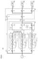
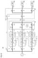
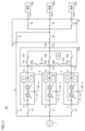
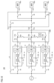
- FIG. 10 is a diagram illustrating a process of stopping and paralleling off an existing UPS; It is a figure explaining the process of removing existing UPS. It is a figure explaining the process of installing new UPS. It is a figure explaining the process of implementing a parallel test.
- FIG. 10 is a diagram illustrating a process of parallel loading UPSs after a parallel test;
- FIG. 10 is a circuit block diagram showing the configuration of an uninterruptible power supply system according to a first modified example;
- FIG. 9 is a circuit block diagram showing the configuration of an uninterruptible power supply system according to a second modification;
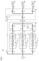
- FIG. 1 is a circuit block diagram showing an example of the configuration of an uninterruptible power supply system according to an embodiment.
- an uninterruptible power supply system 100 includes a plurality of (three in the figure) uninterruptible power supplies (UPS: Uninterruptible Power Supply) 11-13, a plurality of switches 15-18, and a maintenance bypass circuit 6. , a parallel board 20 , a maintenance bypass board 30 , and a test parallel board 40 .
- UPS Uninterruptible Power Supply
- the UPS 11 includes an input terminal T1, a battery terminal T2, an output terminal T3, a converter 2, an inverter 3, a bypass switching circuit 5, and a control circuit 7.
- the input terminal T1 receives commercial-frequency AC power from the commercial AC power supply 1.
- Battery terminal T2 is connected to battery 4 .
- a battery 4 stores DC power.
- a capacitor may be connected instead of the battery 4 .
- the output terminal T3 is connected to the loads 50a-50c through the parallel board 20 and the maintenance bypass board 30.
- the switch 16 is, for example, a breaker, and is connected between the commercial AC power supply 1 and the input terminal T1.
- the switch 16 is normally turned on when the AC power is supplied from the commercial AC power supply 1, and is turned off when the AC power from the commercial AC power supply 1 is stopped.
- the converter 2 receives commercial-frequency AC power from the commercial AC power supply 1 via the switch 16 and is controlled by the control circuit 7 .
- the converter 2 normally converts the AC power supplied from the commercial AC power supply 1 via the switch 16 into DC power and outputs the DC power to the DC line.
- the output voltage of converter 2 can be controlled to a desired value.
- the inverter 3 is connected to the DC line and controlled by the control circuit 7 .
- the inverter 3 converts the DC power supplied from the converter 2 through the DC line into AC power of commercial frequency and outputs the AC power.
- AC power generated by inverter 3 is applied to loads 50a-50c via output terminal T3, parallel board 20 and maintenance bypass board 30.
- the inverter 3 normally converts the DC power supplied from the converter 2 into AC power, and converts the DC power supplied from the battery 4 into AC power during a power failure of the commercial AC power supply 1 .
- the output voltage of the inverter 3 can be controlled to a desired value.
- bypass switching circuit 5 is connected between the input terminal T1 and the output terminal T3 and controlled by the control circuit 7.
- Bypass switching circuit 5 is turned off in an inverter power supply mode in which AC power generated by inverter 3 is supplied to a load, and is turned on in a bypass power supply mode in which AC power is supplied from commercial AC power supply 1 to a load.
- Control circuit 7 normally controls converter 2 and inverter 3 to generate commercial-frequency AC power, and in the event of a power failure, stops operation of converter 2 and controls inverter 3 to generate commercial-frequency AC power. generate.
- Each of UPS 12 and 13 has the same configuration as UPS 11.
- Switch 17 is connected between commercial AC power supply 1 and input terminal T1 of UPS 12 .
- Switch 18 is connected between commercial AC power supply 1 and input terminal T1 of UPS 13 .
- the switches 17 and 18 are normally turned on, and turned off when the commercial AC power supply 1 fails.
- the control circuits 7 of the UPSs 11-13 are connected to each other by a communication cable 8, and information is exchanged between the UPSs 11-13 via the communication cable 8.
- Each control circuit 7 controls the corresponding converter 2 and inverter 3 so that the shared currents of the plurality of UPSs 11-13 are equal.
- Control circuit 7 stops operation of corresponding converter 2 and inverter 3 when the corresponding UPS is to be stopped, and stops operation of corresponding converter 2 and inverter 3 when the corresponding UPS is to be put into the operating state. continue driving.
- the parallel board 20 includes input terminals T11 to T13, an output terminal T14, reactors 21a, 22a and 23a, and switches 21b, 22b and 23b.
- Parallel board 20 corresponds to an embodiment of "first parallel board” and "parallel board”.
- the input terminal T11 is connected to the output terminal T3 of the UPS11.
- the input terminal T12 is connected to the output terminal T3 of the UPS12.
- the input terminal T13 is connected to the output terminal T3 of the UPS11.
- the reactor 21a and the switch 21b are connected in series between the input terminal T11 and the output terminal T14.
- Reactor 22a and switch 22b are connected in series between input terminal T12 and output terminal T14.
- Reactor 23a and switch 23b are connected in series between input terminal T131 and output terminal T14.
- the reactors 21a, 22a, and 23a are provided as reactors for suppressing cross flow.
- the switches 21b, 22b, 23b are circuit breakers, for example.
- the switches 21a, 22a, and 23a are always turned on, and turned off during maintenance (including updating) of the corresponding UPS, for example.
- the maintenance bypass panel 30 includes a bypass input terminal T21, an input terminal T22, at least one (three in the drawing) output terminals T23-T25, and switches 31-35.
- the bypass input terminal T21 is connected to the commercial AC power supply 1 via the maintenance bypass circuit 6 and the switch 15.
- the switch 15 is always turned off, and turned on, for example, during maintenance of the UPSs 11-13.
- the input terminal T22 is connected to the output terminal T14 of the parallel board 20.
- Output terminals T23, T24 and T25 are connected to loads 50a, 50b and 50c, respectively.
- the switch 31 has a first terminal connected to the bypass input terminal T21 and a second terminal connected to the first terminals of the switches 33-35.
- the switch 32 has a first terminal connected to the input terminal T22 and a second terminal connected to the first terminals of the switches 33-35.
- the second terminals of switches 33-35 are connected to output terminals T23-T25, respectively.
- the switch 31 is always turned off, and turned on, for example, during maintenance of the UPSs 11-13.
- the switch 32 is always on, and is turned off during maintenance of the UPS 11-13, for example.
- Each of the switches 33-35 is always turned on, and turned off during maintenance of the corresponding load, for example.
- the test parallel board 40 is used for UPS parallel tests, which will be described later.
- the test parallel board 40 includes a first terminal T31, a second terminal T32, and a reactor 41 connected between the terminals T31 and T32.
- the reactor 41 is provided as a reactor for suppressing cross flow during the parallel test.
- the test parallel board 40 corresponds to an embodiment of "connection circuit” and "second parallel board”.
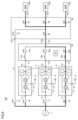
- FIG. 2 is a diagram showing the operating state of the uninterruptible power supply system 100 during normal times. As shown in FIG. 2, the switches 16 to 18, 21b to 23b, and 32 to 35 are normally turned on, and the switches 15 and 31 are turned off.
- Each of the UPSs 11 to 13 receives AC power from a commercial AC power supply 1, and controls a power converter (converter 2 and inverter 3) to supply commercial-frequency AC power, as indicated by a thick solid line in the figure. It generates and outputs the generated AC power to the output terminal T3.
- AC power output from UPS 11-13 is supplied to loads 50a-50c via a plurality of switches included in parallel board 20 and maintenance bypass board 30.
- the control circuits 7 of the UPS 11-13 are connected by a communication cable 8 to form one control device.
- This controller controls the parallel operation of the UPSs 11-13. Specifically, the controller controls the inverters 3 of the UPSs 11-13 based on the currents flowing through the loads 50a, 50b, and 50c. In addition, the control device controls the operating UPS so that the output voltage and output current of the operating UPS are equal to each other.
- the uninterruptible power supply system 100 is configured to obtain redundancy by connecting a plurality of UPSs 11 to 13 in parallel to the load. It is called an uninterruptible power supply system.
- N UPSs are required for power supply by the uninterruptible power supply system 100
- power supply quality can be improved by implementing (N+1) UPSs for redundancy.
- the present embodiment provides an update method that enables UPS update and parallel testing without securing empty space for temporary placement of a new UPS and without the need to install new communication cables. It provides.
- the existing UPS is replaced with a new UPS one by one while continuing to supply power to the load. Then, the newly installed UPS is operated in parallel with other existing UPSs, and a parallel test is carried out to confirm whether or not there is an abnormality in the parallel operation control.
- control circuit 7 of each of the UPSs 11-13 is communicably connected by the communication cable 8. Therefore, when updating the UPS, it is necessary to reconnect the communication cable 8 from the existing UPS to the new UPS in addition to replacing the existing UPS with the new UPS.
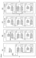
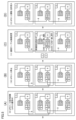
- FIG. 3 is a diagram explaining the communication cable 8 that connects the UPSs 11-13.
- FIG. 3 schematically shows three control circuits 7 and a communication cable 8 included in each of the UPSs 11-13.
- FIG. 3A shows the wiring of the communication cable 8 during parallel operation of the UPSs 11-13.
- control circuit 7 includes a plurality of terminals CAA, CAB, ECAA, ECAB and processor 9 .
- Control circuit 7 further includes a memory (not shown).
- the control circuit 7 can perform the above-described parallel operation control by software processing in which the processor 9 executes a program stored in memory in advance.
- part or all of the parallel operation control can be realized by hardware processing using a built-in dedicated electronic circuit instead of software processing.
- Each of the terminals CAA, CAB, ECAA, and ECAB is configured so that connectors 81 and 82 provided at both ends of the communication cable 8 can be connected.
- Terminals CAA and CAB are connected to each other and to the processor 9 .
- Terminals CAA and CAB are used to communicatively connect the control circuit 7 to the control circuit 7 of another UPS.
- Terminals ECAA and ECAB are spare terminals.
- Terminals ECAA and ECAB are connected to each other and to the processor 9 .
- a terminating resistor E is used to terminate the end of the communication cable 8 .
- the control circuit 7 of the UPS 11 and the control circuit 7 of the UPS 12 are connected by a communication cable 8. Specifically, connector 81 of communication cable 8 is connected to terminal CAB of UPS 11 , and connector 82 is connected to terminal CAA of UPS 12 . Since the terminal CAA of the UPS 11 is not used, a terminating resistor E is connected to it.
- the control circuit 7 of the UPS 12 and the control circuit 7 of the UPS 13 are connected by a communication cable 8. Specifically, connector 81 of communication cable 8 is connected to terminal CAB of UPS 12 , and connector 82 is connected to terminal CAA of UPS 13 . Since the terminal CAB of the UPS 13 is not used, a terminating resistor E is connected to it. With the wiring shown in FIG. 3A, the control circuits 7 (processors 9) of the UPSs 11 to 13 can be connected with the communication cables 8 to form the control device described above. In each of the UPSs 11, 12, 13, spare terminals ECAA, ECAB are not used.
- FIG. 1 the procedure for updating the UPS 11 will be explained using FIGS. 3 to 10.
- FIG. 1 the major flow is shown below.
- UPS 11 to 13 are operated in parallel to supply power to the load (initial state).
- UPS 11 and another UPS for example, UPS 12 are stopped and disconnected.
- UPS 12 is turned on in parallel and started, and UPS 12 and 13 are operated in parallel.
- UPSs 11 and 12 are connected in parallel and activated to return to the initial state.
- the UPS 11 and UPS 12 are disconnected from the parallel operation of the UPS 11-13.
- the UPS 13 is maintained in an operating state, so the UPS 13 continues to supply power to the loads 50a to 50c.
- a terminating resistor E is connected to the terminal CAB, and the terminating resistor E is connected to the terminal CAA via the communication cable 8 and the terminals CAB and CAA of the UPS 12 .
- the UPS 13 alone can continue to operate.
- UPS12 is connected in parallel with UPS13.
- the UPS 12 and 13 are operated in parallel by the control circuit 7 of the UPS 12 controlling the power converter (the converter 2 and the inverter 3) so as to start the UPS 12 and synchronize with the output of the UPS 13 in the operating state ( See Figure 7).
- the UPS 11 installs a new UPS. Further, the communication cable 8 is connected between the UPSs 11 and 122 by inserting the connector 81 of the communication cable 8 into the terminal CAB of the new UPS. During work, the UPSs 12, 13 are kept in operation, and the UPSs 12, 13 supply power to the loads 50a-50c.
- This step is performed to connect the UPS 11 and UPS 12 and disconnect the communication connection between the UPS 12 and UPS 13 .
- the connection destination of the connector 82 of the communication cable 8 is changed from the terminal ECAA to the terminal CAB.
- the connection destination of the connector 81 of the communication cable 8 is changed from the terminal CAB to the terminal ECAA.
- the terminating resistor E is connected to the terminal CAB, and the terminating resistor E is connected to the terminal CAA via the communication cable 8 and the terminals ECAA and ECAB of the UPS 12. Therefore, the UPS 13 can be operated alone. can be continued.
- the terminals CAB are connected to each other via the communication cable 8, so that parallel operation is possible.
- test parallel board 40 (reactor 41) is connected between output terminal T3 of UPS 11 and output terminal T3 of UPS 12 do. In this state, the UPSs 11 and 12 are activated and a parallel test is performed. During the parallel test, the UPS 13 remains in operation and the loads 50a-50c are being supplied by the UPS 13.
- each of the UPSs 11 and 12 performs no-load operation.
- control circuit 7 controls the corresponding power converter so that the output voltages (phase and amplitude) of UPS 11, 12 are equal to each other.
- no current flows between the output terminals T3 of the UPSs 11 and 12.
- the output voltages of the UPSs 11 and 12 are different (at least one of phase and amplitude is different)
- a current flows between the output terminals T3 of the UPSs 11 and 12. Therefore, based on whether a current (cross current) flows between the output terminals T3 of the UPSs 11, 12, it can be confirmed whether the parallel operation control of the UPSs 11, 12 is normally performed.
- the reactor 41 has a function of suppressing cross currents during parallel operation.
- the parallel test may be configured to be performed with a simulated load connected to the output terminals T3 of the UPSs 11 and 12 instead of the no-load operation. In this case, based on whether the output current of the UPS 11 and the output current of the UPS 12 are in balance, it can be confirmed whether the parallel operation control of the UPSs 11 and 12 is being performed normally.
- UPS 11, 12 startup/parallel connection Next, referring to FIG. 5(D) and FIG.
- the UPSs 11 and 12 are connected in parallel to the UPS 13 in operation. Furthermore, the control circuit 7 of the UPS 11, 12 controls the power converters (converter 2 and inverter 3) so as to activate the UPS 11, 12 and synchronize with the output of the UPS 13 in the operating state. As a result, the UPSs 11 to 13 are initialized, and parallel operation of the UPSs 11 to 13 is performed (see FIG. 10).
- one UPS to be updated and another UPS are By disconnecting from parallel operation and connecting a cross current suppression reactor between the output terminals of these two UPSs, while continuing to supply power to the load, the UPS is updated and the parallel test is performed on the two UPSs. and can be implemented. Therefore, a plurality of UPSs can be updated one by one and a parallel test can be performed while continuing to supply power to the load. According to this, there is no need to secure empty space for temporary installation of all the new UPSs, and it is not necessary to procure new communication cables. becomes possible.
- a communication cable for communication connection between a plurality of control circuits is used to connect communication between the control circuits of the two UPSs while updating one UPS.
- the wiring of the communication cable so as to cut off the communication between the control circuit and the control circuit of the other UPS, the power supply to the load by the other UPS and the parallel test for the two UPSs can be performed in parallel. It is possible to execute
- FIG. 11 is a circuit block diagram showing the configuration of an uninterruptible power supply system according to the first modified example.
- uninterruptible power supply system 100 according to the first modification is different from uninterruptible power supply system 100 shown in FIG. They are different in terms of preparation.
- the parallel board 20A is obtained by adding reactors 41a and 41b and switches 42a and 42b to the parallel board 20 of FIG.
- Reactor 41a and switch 42a are connected in series between input terminal T11 and input terminal T12.
- Reactor 41b and switch 42b are connected in series between input terminal T12 and input terminal T13.
- Reactors 41a, 41b and switches 42a, 42b correspond to an example of a "connection circuit”.
- Switches 42a and 42b correspond to one embodiment of a "fourth switch.”
- the switch 42a is turned off while the switches 21b, 22b, and 23b are turned on.
- the switch 42a is turned on when the switches 21b and 22b are turned off and the switch 23b is turned on.
- the reactor 41a is connected between the output terminal T3 of the UPS 11 and the output terminal T3 of the UPS 12, so that the UPSs 11 and 12 can be tested in parallel.
- the switch 42b is turned off while the switches 21b, 22b, and 23b are turned on.
- the switch 42b is turned on when the switches 22b and 23b are turned off and the switch 21b is turned on.
- the reactor 41b is connected between the output terminal T3 of the UPS 12 and the output terminal T3 of the UPS 13, so that the UPSs 12 and 13 can be tested in parallel.
- FIG. 12 is a circuit block diagram showing the configuration of an uninterruptible power supply system according to the second modified example.
- uninterruptible power supply system 100 according to a second modification is different from uninterruptible power supply system 100 shown in FIG. They are different in terms of preparation.
- a parallel board 20B is obtained by adding switches 43a and 43b to the parallel board 20 of FIG.
- Switch 43a is connected between a connection node of reactor 21a and switch 21b and a connection node of reactor 22a and switch 22b.
- Switch 43b is connected between a connection node of reactor 22a and switch 22b and a connection node of reactor 23a and switch 23b.
- Reactors 21a, 22a, 23a and switches 43a, 43b correspond to an embodiment of the "connection circuit”.
- Switches 43a and 43b correspond to one embodiment of the "fourth switch”.
- the switch 43a is turned off while the switches 21b, 22b, and 23b are turned on.
- the switch 43a is turned on when the switches 21b and 22b are turned off and the switch 23b is turned on.
- Reactors 21a and 22a are connected in series between output terminal T3 of UPS 11 and output terminal T3 of UPS 12 by turning on switch 43a. Since the series circuit of the reactors 21a and 22a functions as a reactor for suppressing the cross current, the UPSs 11 and 12 can be tested in parallel.
- the switch 43b is turned off while the switches 21b, 22b, and 23b are turned on.
- the switch 43b is turned on when the switches 22b and 23b are turned off and the switch 21b is turned on.
- Reactors 22a and 23a are connected in series between output terminal T3 of UPS 12 and output terminal T3 of UPS 13 by turning on switch 43b. Since the series circuit of the reactors 22a and 23a functions as a reactor for suppressing the cross current, the UPSs 12 and 13 can be tested in parallel.
- UPSs a parallel redundant uninterruptible power supply system including three UPSs was described, but in the uninterruptible power supply system according to the present disclosure, the The number of UPSs may be three or more.
Landscapes
- Engineering & Computer Science (AREA)
- Power Engineering (AREA)
- Business, Economics & Management (AREA)
- Emergency Management (AREA)
- Stand-By Power Supply Arrangements (AREA)
- Inverter Devices (AREA)
Abstract
無停電電源システム(100)は、複数のUPSと、複数のUPSを負荷に対して並列に接続するための複数のスイッチと、接続回路(40)とを備える。各UPSは、所定周波数の交流電圧を生成する電力変換器(3)と、電力変換器により生成された交流電圧を出力する出力端子(T3)とを含む。複数のスイッチは、第1のUPS(11)の出力端子と負荷との間に接続される第1のスイッチ(21b)と、第2のUPS(12)の出力端子と負荷との間に接続される第2のスイッチ(22b)と、第3のUPS(13)の出力端子と負荷との間に接続される第3のスイッチ(23b)とを含む。接続回路(40)は、第1および第2のスイッチがオフされ、かつ、第3のスイッチがオンされた状態において、第1のUPSの出力端子と第2のUPSの出力端子との間にリアクトル(41)を接続するように構成される。
Description
本開示は、無停電電源システムおよび無停電電源システムの更新方法に関する。
特開2017-50933号公報(特許文献1)には、並列冗長方式の無停電電源システムが開示される。並列冗長方式の無停電電源システムは、負荷に対して並列接続された複数の無停電電源装置(UPS:Uninterruptible Power Supply)を備えている。
上記並列冗長方式の無停電電源システムにおいて、複数の既設UPSの各々を新設UPSに更新する場合には、更新された複数のUPSの並列運転制御に異常がないかを確認するための試験(以下、「並列試験」とも称する)を実施する必要がある。その一方で、UPSの更新作業中においても、負荷への給電を継続させることが求められる。
そのため、従来、負荷への給電を継続しながら並列試験を実施するために、新設UPSのすべてを既設UPSとは別のスペースに仮置きし、並列試験を実施して並列運転に異常がないかを確認する作業が行われていた。そして、この作業を終了した後に、既設UPSを停止して撤去する作業と、新設UPSによる給電への切り換え作業とが行われていた。
上述した手順では、現地に新設UPSのすべてを仮置きするための空きスペースが必要とされるため、空きスペースがない場合には更新作業が困難となることが懸念される。また、新設UPSを既設UPSとは別のスペースに仮置きして運転可能状態とする必要があるため、本来であれば流用可能である通信ケーブルも新規に調達して配設しなければならず、工事費用が嵩んでしまうことが懸念される。
本開示は上述のような課題を解決するためになされたものであって、本開示の目的は、並列冗長方式の無停電電源システムにおいて、負荷への給電を継続しながら無停電電源装置を1台ずつ更新および並列試験の実施を可能とすることである。
本開示の一態様に係る無停電電源システムは、第1から第3の無停電電源装置を含む複数の無停電電源装置と、複数の無停電電源装置を負荷に対して並列に接続するための複数のスイッチとを備える。複数の無停電電源装置の各々は、所定周波数の交流電圧を生成する電力変換器と、電力変換器により生成された交流電圧を出力する出力端子とを含む。複数のスイッチは、第1の無停電電源装置の出力端子と負荷との間に接続される第1のスイッチと、第2の無停電電源装置の出力端子と負荷との間に接続される第2のスイッチと、第3の無停電電源装置の出力端子と負荷との間に接続される第3のスイッチとを含む。無停電電源システムは、接続回路をさらに備える。接続回路は、第1および第2のスイッチがオフされ、かつ、第3のスイッチがオンされた状態において、第1の無停電電源装置の出力端子と第2の無停電電源装置の出力端子との間にリアクトルを接続するように構成される。
本開示の別の態様に係る無停電電源システムの更新方法は、各々が出力端子を有する第1から第3の無停電電源装置と、第1から第3の無停電電源装置の出力端子を負荷にそれぞれ接続するための第1から第3のスイッチとを含む無停電電源システムの更新方法である。第1から第3の無停電電源装置の各々は、電力変換器を含み、電力変換器により生成された所定周波数の交流電圧を出力端子に出力するように構成される。更新方法は、第1から第3のスイッチがオンした状態で第1から第3の無停電電源装置が並列運転している場合において、第1および第2の無停電電源装置の運転を停止し、かつ、第1および第2のスイッチをオフするステップと、第1の無停電電源装置において、既設の無停電電源装置を新設の無停電電源装置に更新するステップと、更新された第1の無停電電源装置の出力端子と、第2の無停電電源装置の出力端子との間にリアクトルを接続するステップと、互いに等しい交流電圧を出力端子に出力するように第1および第2の無停電電源装置の各々の電力変換器を制御することにより、第1および第2の無停電電源装置の並列試験を実施するステップと、並列試験の実施後に、第1および第2の無停電電源装置の運転を停止し、第1および第2の無停電電源装置からリアクトルを取り外すステップと、第1および第2のスイッチをオンし、第1および第2の無停電電源装置を起動させることにより、第1から第3の無停電電源装置を並列運転させるステップとを備える。
本開示によれば、並列冗長方式の無停電電源システムにおいて、負荷への給電を継続しながら無停電電源装置を1台ずつ更新および並列試験を実施することができる。
以下、図面を参照しつつ、本開示の実施の形態について説明する。以下の説明では、同一の部品および構成要素には同一の符号を付してある。それらの名称および機能も同じである。したがって、これらについての詳細な説明は原則的には繰り返さない。
<無停電電源システムの構成>
図1は、実施の形態に係る無停電電源システムの構成の一例を示す回路ブロック図である。
図1は、実施の形態に係る無停電電源システムの構成の一例を示す回路ブロック図である。
図1を参照して、無停電電源システム100は、複数(図では3つ)の無停電電源装置(UPS:Uninterruptible Power Supply)11~13と、複数のスイッチ15~18と、保守バイパス回路6と、並列盤20と、保守バイパス盤30と、試験並列盤40とを備える。
UPS11は、入力端子T1、バッテリ端子T2、出力端子T3、コンバータ2、インバータ3、バイパス切換回路5、および制御回路7を含む。
入力端子T1は、商用交流電源1から商用周波数の交流電力を受ける。バッテリ端子T2はバッテリ4に接続される。バッテリ4は直流電力を蓄える。バッテリ4の代わりにコンデンサが接続されていても構わない。出力端子T3は、並列盤20および保守バイパス盤30を介して負荷50a~50cに接続される。
スイッチ16は、例えば遮断器であり、商用交流電源1と入力端子T1との間に接続される。スイッチ16は、商用交流電源1から交流電力が供給されている通常時はオンされ、商用交流電源1からの交流電力が停止された停電時はオフされる。
コンバータ2は、商用交流電源1からスイッチ16を介して商用周波数の交流電力を受け、制御回路7によって制御される。コンバータ2は、通常時は、商用交流電源1からスイッチ16を介して供給される交流電力を直流電力に変換して直流ラインに出力する。コンバータ2の出力電圧は、所望の値に制御可能になっている。商用交流電源1の停電時には、コンバータ2の運転は停止される。
インバータ3は、直流ラインに接続され、制御回路7によって制御される。インバータ3は、コンバータ2から直流ラインを介して供給される直流電力を商用周波数の交流電力に変換して出力する。インバータ3で生成された交流電力は、出力端子T3、並列盤20および保守バイパス盤30を介して負荷50a~50cに与えられる。インバータ3は、通常時には、コンバータ2から供給される直流電力を交流電力に変換し、商用交流電源1の停電時には、バッテリ4から供給される直流電力を交流電力に変換する。インバータ3の出力電圧は、所望の値に制御可能になっている。
バイパス切換回路5は、入力端子T1と出力端子T3との間に接続され、制御回路7によって制御される。バイパス切換回路5は、インバータ3によって生成された交流電力を負荷に供給するインバータ給電モード時はオフされ、商用交流電源1から負荷に交流電力を供給するバイパス給電モード時にはオンされる。
制御回路7は、通常時は、コンバータ2およびインバータ3を制御して商用周波数の交流電力を生成させ、停電時には、コンバータ2の運転を停止するとともにインバータ3を制御して商用周波数の交流電力を生成させる。
UPS12,13の各々は、UPS11と同じ構成である。スイッチ17は、商用交流電源1とUPS12の入力端子T1との間に接続される。スイッチ18は、商用交流電源1とUPS13の入力端子T1との間に接続される。スイッチ17,18は、通常時はオンされ、商用交流電源1の停電時はオフされる。
UPS11~13の各々の制御回路7は通信ケーブル8によって互いに接続されており、通信ケーブル8を介してUPS11~13の間で情報の授受を行う。各制御回路7は、複数のUPS11~13の分担電流が等しくなるように、対応するコンバータ2およびインバータ3を制御する。
また、制御回路7は、対応するUPSを停止状態にさせる場合には、対応するコンバータ2およびインバータ3の運転を停止させ、対応するUPSを運転状態にさせる場合は対応するコンバータ2およびインバータ3の運転を継続させる。
並列盤20は、入力端子T11~T13と、出力端子T14と、リアクトル21a,22a,23aと、スイッチ21b,22b,23bとを含む。並列盤20は「第1の並列盤」および「並列盤」の一実施例に対応する。
入力端子T11は、UPS11の出力端子T3に接続される。入力端子T12は、UPS12の出力端子T3に接続される。入力端子T13は、UPS11の出力端子T3に接続される。
リアクトル21aおよびスイッチ21bは、入力端子T11と出力端子T14との間に直列に接続される。リアクトル22aおよびスイッチ22bは、入力端子T12と出力端子T14との間に直列に接続される。リアクトル23aおよびスイッチ23bは、入力端子T131と出力端子T14との間に直列に接続される。
リアクトル21a,22a,23aは横流抑制用のリアクトルとして設けられる。スイッチ21b,22b,23bは、例えば遮断器である。スイッチ21a,22a,23aは、常時オンされ、例えば、対応するUPSのメンテナンス時(更新時を含む)にそれぞれオフされる。
保守バイパス盤30は、バイパス入力端子T21と、入力端子T22と、少なくとも1つ(図では3つ)の出力端子T23~T25と、スイッチ31~35とを含む。
バイパス入力端子T21は、保守バイパス回路6およびスイッチ15を介して商用交流電源1に接続される。スイッチ15は、常時オフされ、例えば、UPS11~13のメンテナンス時にオンされる。
入力端子T22は、並列盤20の出力端子T14に接続される。出力端子T23,T24,T25は負荷50a,50b,50cにそれぞれ接続される。
スイッチ31は、第1の端子がバイパス入力端子T21に接続され、第2の端子がスイッチ33~35の第1の端子に接続される。スイッチ32は、第1の端子が入力端子T22に接続され、第2の端子がスイッチ33~35の第1の端子に接続される。スイッチ33~35の第2の端子は、出力端子T23~T25にそれぞれ接続される。
スイッチ31は、常時オフされ、例えば、UPS11~13のメンテナンス時にオンされる。スイッチ32は、常時オンされ、例えば、UPS11~13のメンテナンス時にオフされる。スイッチ33~35の各々は、常時オンされ、例えば、対応する負荷のメンテナンス時にオフされる。
試験並列盤40は、後述するUPSの並列試験に用いられる。試験並列盤40は、第1の端子T31と、第2の端子T32と、端子T31,T32の間に接続されるリアクトル41とを含む。リアクトル41は、並列試験中の横流抑制用のリアクトルとして設けられる。試験並列盤40は「接続回路」および「第2の並列盤」の一実施例に対応する。
次に、図1に示した無停電電源システム100の動作を説明する。
図2は、通常時における無停電電源システム100の運用状態を示す図である。図2に示すように、通常時には、スイッチ16~18,21b~23b,32~35がオンされ、スイッチ15,31がオフされる。
図2は、通常時における無停電電源システム100の運用状態を示す図である。図2に示すように、通常時には、スイッチ16~18,21b~23b,32~35がオンされ、スイッチ15,31がオフされる。
UPS11~13の各々は、図中に太実線で示されるように、商用交流電源1から交流電力の供給を受け、電力変換器(コンバータ2およびインバータ3)を制御して商用周波数の交流電力を生成し、生成した交流電力を出力端子T3に出力する。UPS11~13から出力される交流電力は、並列盤20および保守バイパス盤30に含まれる複数のスイッチを経由して負荷50a~50cに供給される。
UPS11~13の制御回路7は、通信ケーブル8で結合されて1つの制御装置を構成する。この制御装置は、UPS11~13の並列運転を制御する。具体的には、制御装置は、負荷50a,50b,50cに流れる電流に基づいて、UPS11~13のインバータ3を制御する。また、制御装置は、運転中のUPSの出力電圧および出力電流が互いに等しくなるように、運転中のUPSを制御する。
以上説明したように、本実施の形態に係る無停電電源システム100は、複数のUPS11~13を負荷に対して並列に接続して冗長性を得るように構成されるため、「並列冗長方式の無停電電源システム」と称される。無停電電源システム100による電源供給にN台のUPSが必要な場合、(N+1)台のUPSを実装して冗長化を図ることにより、電源品質を向上させることができる。
並列冗長方式の無停電電源システムにおいて、複数のUPSを既設UPSから新設UPSに更新する場合には、更新された複数のUPSの並列運転制御に異常がないかを確認するための試験(以下、「並列試験」とも称する)を実施する必要がある。その一方で、UPSの更新作業中においても、負荷への給電を継続させることが求められる。そのため、従来、負荷への給電を継続しつつ並列試験を実施するために、以下の手順に従って更新作業が行われていた。
(1)新設UPSのすべてを既設UPSとは別のスペースに仮置きし、並列試験を実施して並列運転制御に異常がないかを確認する。
(2)負荷給電している既設UPSを一旦保守バイパス給電とし、その間に新設UPSへ負荷を切り換え、新設UPSによる負荷給電状態とする。
(3)既設UPSを停止かつ撤去し、別の仮置きスペースに移設して、再び運転可能状態に復旧する。
(4)負荷給電している新設UPSから保守バイパス給電を介して仮設の既設UPSによる給電に切り換え、新設UPSを停止する。
(5)停止中の新設UPSを仮設場所から正規の据え付け場所に移設する。
(6)仮設の既設UPSによる給電から新設UPSによる給電へ切り換え作業を行う。
(6)仮設の既設UPSによる給電から新設UPSによる給電へ切り換え作業を行う。
(7)停止状態の既設UPSを仮設場所から撤去する。
上述した手順では、現地に新設UPSのすべてを仮置きするための空きスペースが必要とされるため、現地に空きスペースを確保できない場合には更新作業が困難となることが懸念される。また、新設UPSを既設UPSとは別のスペースに仮置きして運転可能状態とする必要があるため、本来であれば流用可能である通信ケーブルも新規に調達して配設しなければならず、工事費用が嵩んでしまうことが懸念される。
上述した手順では、現地に新設UPSのすべてを仮置きするための空きスペースが必要とされるため、現地に空きスペースを確保できない場合には更新作業が困難となることが懸念される。また、新設UPSを既設UPSとは別のスペースに仮置きして運転可能状態とする必要があるため、本来であれば流用可能である通信ケーブルも新規に調達して配設しなければならず、工事費用が嵩んでしまうことが懸念される。
本実施の形態は、新設UPSを仮置きするための空きスペースの確保、および、新規の通信ケーブルの配設を必要とすることなく、UPSの更新および並列試験の実施を可能とする更新方法を提供するものである。
<無停電電源システムの更新方法>
次に、図1に示した無停電電源システム100におけるUPSの更新方法について説明する。以下の説明では、一例として、3台のUPS11~13の並列運転(図2参照)の実行中にUPS11を更新する手順について説明する。すなわち、本例では、UPS11は「第1の無停電電源装置」に対応し、UPS12は「第2の無停電電源装置」に対応し、UPS13は「第3の無停電電源装置」に対応する。
次に、図1に示した無停電電源システム100におけるUPSの更新方法について説明する。以下の説明では、一例として、3台のUPS11~13の並列運転(図2参照)の実行中にUPS11を更新する手順について説明する。すなわち、本例では、UPS11は「第1の無停電電源装置」に対応し、UPS12は「第2の無停電電源装置」に対応し、UPS13は「第3の無停電電源装置」に対応する。
本実施の形態では、以下に述べるように、負荷への給電を継続しながら、UPSを1台ずつ既設UPSから新設UPSに取り替える。そして、この新設UPSを他の既設UPSと並列運転させて並列試験を実施し、並列運転制御に異常がないかを確認する。
上述したように、UPS11~13の各々の制御回路7は、通信ケーブル8によって通信可能に接続されている。したがって、UPSの更新においては、既設UPSを新設UPSに取り替える作業に併せて、通信ケーブル8を既設UPSから新設UPSに接続し直す作業が必要となる。
図3は、UPS11~13間を繋ぐ通信ケーブル8を説明する図である。図3には、UPS11~13にそれぞれ含まれる3つの制御回路7と、通信ケーブル8とが模式的に示されている。図3(A)は、UPS11~13の並列運転時における通信ケーブル8の配線を示している。
図3(A)を参照して、制御回路7は、複数の端子CAA,CAB,ECAA,ECABと、プロセッサ9とを含む。制御回路7は、図示しないメモリをさらに含む。制御回路7は、予めメモリに格納されたプログラムをプロセッサ9が実行するソフトウェア処理によって、上述した並列運転制御を実行することができる。あるいは、並列運転制御の一部または全部について、ソフトウェア処理に代えて、内蔵された専用の電子回路などを用いたハードウェア処理によって実現することも可能である。
端子CAA,CAB,ECAA,ECABの各々は、通信ケーブル8の両端に設けられたコネクタ81,82を接続することが可能に構成されている。端子CAA,CABは、互いに接続され、かつ、プロセッサ9に接続されている。端子CAA,CABは、制御回路7を他のUPSの制御回路7に通信接続するために用いられる。端子ECAA,ECABは、予備用の端子である。端子ECAA,ECABは互いに接続され、かつ、プロセッサ9に接続されている。終端抵抗Eは、通信ケーブル8の端部を終端させるために用いられる。
UPS11の制御回路7とUPS12の制御回路7とは通信ケーブル8によって接続されている。具体的には、通信ケーブル8のコネクタ81はUPS11の端子CABに接続され、コネクタ82はUPS12の端子CAAに接続されている。UPS11の端子CAAは不使用のため、終端抵抗Eが接続されている。
UPS12の制御回路7とUPS13の制御回路7とは通信ケーブル8によって接続されている。具体的には、通信ケーブル8のコネクタ81はUPS12の端子CABに接続され、コネクタ82はUPS13の端子CAAに接続されている。UPS13の端子CABは不使用のため、終端抵抗Eが接続されている。図3(A)に示す配線によって、UPS11~13の制御回路7(プロセッサ9)は、通信ケーブル8で結合されて上述した制御装置を構成することができる。UPS11,12,13の各々において、予備用の端子ECAA,ECABは不使用となっている。
次に、図3から図10を用いて、UPS11を更新する手順を説明する。まず、大きな流れを以下に示す。
(1)UPS11~13を並列運転して負荷に給電している状態とする(初期状態)。
(2)UPS11および他の1台のUPS(例えばUPS12)を停止、解列させる。
(2)UPS11および他の1台のUPS(例えばUPS12)を停止、解列させる。
(3)UPS11,12間の通信ケーブル8の接続を変更する。
(4)UPS12を並列投入かつ起動し、UPS12,13を並列運転させる。
(4)UPS12を並列投入かつ起動し、UPS12,13を並列運転させる。
(5)UPS11にて、停止状態の既設UPSを撤去する。
(6)UPS11にて、新設UPSを据え付ける。
(6)UPS11にて、新設UPSを据え付ける。
(7)UPS12を停止、解列させる。
(8)UPS11~13間の通信ケーブル8の接続を変更する。
(8)UPS11~13間の通信ケーブル8の接続を変更する。
(9)UPS11,12間に試験並列盤40を接続し、並列試験を実施する。
(10)UPS11,12を停止する。
(10)UPS11,12を停止する。
(11)UPS11~13間の通信ケーブル8の接続を変更する。
(12)UPS11,12を並列投入かつ起動し、初期状態に戻す。
(12)UPS11,12を並列投入かつ起動し、初期状態に戻す。
次に、上記(2)から(12)の各々の工程について説明する。なお、(1)の初期状態については図2に示されているため、説明を省略する。
(2)UPS11,12の停止・解列
図3(B)および図6を参照して、UPS11~13の並列運転中、更新対象のUPS11および、2台のUPS12,13のうちの1台のUPS(図ではUPS12)の運転を停止させる。具体的には、UPS11,12の各々において、制御回路7はコンバータ2およびインバータ3の運転を停止させ、対応するUPSを停止状態とする。
図3(B)および図6を参照して、UPS11~13の並列運転中、更新対象のUPS11および、2台のUPS12,13のうちの1台のUPS(図ではUPS12)の運転を停止させる。具体的には、UPS11,12の各々において、制御回路7はコンバータ2およびインバータ3の運転を停止させ、対応するUPSを停止状態とする。
さらに、スイッチ11,12をオフするとともに、並列盤20内のスイッチ21b,22bをオフすることにより、UPS11~13の並列運転からUPS11,UPS12を解列させる。なお、図6中に太実線で示されるように、UPS13は運転状態に維持されているため、UPS13によって負荷50a~50cへの給電が継続されている。
(3)通信ケーブル8の接続変更
次に、図3(C)に示すように、UPS11,12を停止状態に維持し、UPS11,12間を繋ぐ通信ケーブル8の接続を変更する。この工程は、UPS13の運転を確保しつつ、UPS11とUPS13との通信接続を遮断するために行われる。具体的には、通信ケーブル8のコネクタ81をUPS11の端子CABから引き抜くとともに、コネクタ82をUPS12の端子CAAから端子ECAAに差し替える。さらに、UPS12の端子CAA,ECABに終端抵抗Eを接続する。UPS13においては、端子CABに終端抵抗Eが接続されるとともに、端子CAAには通信ケーブル8、UPS12の端子CAB,CAAを介して終端抵抗Eが接続される。これにより、UPS13単体で運転を継続することができる。
次に、図3(C)に示すように、UPS11,12を停止状態に維持し、UPS11,12間を繋ぐ通信ケーブル8の接続を変更する。この工程は、UPS13の運転を確保しつつ、UPS11とUPS13との通信接続を遮断するために行われる。具体的には、通信ケーブル8のコネクタ81をUPS11の端子CABから引き抜くとともに、コネクタ82をUPS12の端子CAAから端子ECAAに差し替える。さらに、UPS12の端子CAA,ECABに終端抵抗Eを接続する。UPS13においては、端子CABに終端抵抗Eが接続されるとともに、端子CAAには通信ケーブル8、UPS12の端子CAB,CAAを介して終端抵抗Eが接続される。これにより、UPS13単体で運転を継続することができる。
(4)UPS12,13の並列運転
次に、図3(D)および図7を参照して、UPS11,12間の通信ケーブル8の接続を変更した後に、スイッチ12,22bをオンすることにより、UPS12をUPS13に並列接続させる。
次に、図3(D)および図7を参照して、UPS11,12間の通信ケーブル8の接続を変更した後に、スイッチ12,22bをオンすることにより、UPS12をUPS13に並列接続させる。
さらに、UPS12を起動させて、運転状態のUPS13の出力と同期するように、UPS12の制御回路7が電力変換器(コンバータ2およびインバータ3)を制御することにより、UPS12,13を並列運転させる(図7参照)。
(5)既設UPSの撤去
次に、図4(A)および図7を参照して、UPS12,13の並列運転の実行中において、UPS11では、通信ケーブル8を抜き取り、既設UPSを撤去する。
次に、図4(A)および図7を参照して、UPS12,13の並列運転の実行中において、UPS11では、通信ケーブル8を抜き取り、既設UPSを撤去する。
(6)新設UPSの据え付け
次に、図4(B)を参照して、UPS11にて、新設UPSを据え付ける。さらに、通信ケーブル8のコネクタ81を新設UPSの端子CABに挿入することにより、UPS11,122間に通信ケーブル8を接続する。作業中、UPS12,13は運転状態に維持されており、UPS12,13によって負荷50a~50cへの給電が行われている。
次に、図4(B)を参照して、UPS11にて、新設UPSを据え付ける。さらに、通信ケーブル8のコネクタ81を新設UPSの端子CABに挿入することにより、UPS11,122間に通信ケーブル8を接続する。作業中、UPS12,13は運転状態に維持されており、UPS12,13によって負荷50a~50cへの給電が行われている。
(7)UPS12の停止・解列
次に、図4(C)および図8を参照して、UPS12の運転を停止させる。さらに、スイッチ12,22bをオフすることにより、UPS12,13の並列回路からUPS12を解列させる。
次に、図4(C)および図8を参照して、UPS12の運転を停止させる。さらに、スイッチ12,22bをオフすることにより、UPS12,13の並列回路からUPS12を解列させる。
(8)通信ケーブル8の接続変更
次に、図4(D)を参照して、UPS11,12間の通信ケーブル8の接続を変更するとともに、UPS12,13間の通信ケーブル8の接続を変更する。この工程は、UPS11とUPS12とを通信接続するとともに、UPS12とUPS13との通信接続を遮断するために行われる。具体的には、UPS12において、通信ケーブル8のコネクタ82の接続先を端子ECAAから端子CABに変更する。また、通信ケーブル8のコネクタ81の接続先を端子CABから端子ECAAに変更する。これによると、UPS13においては、端子CABに終端抵抗Eが接続されるとともに、端子CAAには通信ケーブル8、UPS12の端子ECAA,ECABを介して終端抵抗Eが接続されるため、UPS13単体で運転を継続することができる。また、UPS11およびUPS12においては、各々の端子CAB同士が通信ケーブル8を介して接続されたことによって、並列運転が可能な状態となる。
次に、図4(D)を参照して、UPS11,12間の通信ケーブル8の接続を変更するとともに、UPS12,13間の通信ケーブル8の接続を変更する。この工程は、UPS11とUPS12とを通信接続するとともに、UPS12とUPS13との通信接続を遮断するために行われる。具体的には、UPS12において、通信ケーブル8のコネクタ82の接続先を端子ECAAから端子CABに変更する。また、通信ケーブル8のコネクタ81の接続先を端子CABから端子ECAAに変更する。これによると、UPS13においては、端子CABに終端抵抗Eが接続されるとともに、端子CAAには通信ケーブル8、UPS12の端子ECAA,ECABを介して終端抵抗Eが接続されるため、UPS13単体で運転を継続することができる。また、UPS11およびUPS12においては、各々の端子CAB同士が通信ケーブル8を介して接続されたことによって、並列運転が可能な状態となる。
(9)UPS11,12の並列試験
次に、図5(A)および図9を参照して、UPS11の出力端子T3とUPS12の出力端子T3との間に試験並列盤40(リアクトル41)を接続する。この状態でUPS11,12を起動させて並列試験を実施する。並列試験中、UPS13は運転状態に維持されており、UPS13によって負荷50a~50cへの給電が行われている。
次に、図5(A)および図9を参照して、UPS11の出力端子T3とUPS12の出力端子T3との間に試験並列盤40(リアクトル41)を接続する。この状態でUPS11,12を起動させて並列試験を実施する。並列試験中、UPS13は運転状態に維持されており、UPS13によって負荷50a~50cへの給電が行われている。
並列試験中、UPS11,12の各々は無負荷運転を実行する。UPS11,12の各々において、制御回路7は、UPS11,12の出力電圧(位相および振幅)が互いに等しくなるように、対応する電力変換器を制御する。UPS11,12の出力電圧が互いに等しい場合には、UPS11,12の出力端子T3の間に電流が流れない。一方、UPS11,12の出力電圧が異なる場合(位相および振幅の少なくとも一方が異なる場合)には、UPS11,12の出力端子T3の間に電流が流れる。したがって、UPS11,12の出力端子T3間に電流(横流)が流れるか否かに基づいて、UPS11,12の並列運転制御が正常に行なわれているか否かを確認することができる。リアクトル41は、並列運転中の横流を抑制する機能を有する。
なお、並列試験は、無負荷運転に代えて、UPS11,12の出力端子T3に模擬負荷を接続した状態で実施する構成としてもよい。この場合、UPS11の出力電流とUPS12の出力電流とがバランスしているか否かに基づいて、UPS11,12の並列運転制御が正常に行われているか否かを確認することができる。
(10)UPS11,12の停止
次に、図5(B)を参照して、並列運転を実行した後に、UPS11,12の運転を停止させる。さらに、UPS11の出力端子T3およびUPS12の出力端子T3から試験並列盤40(リアクトル41)を取り外す。
次に、図5(B)を参照して、並列運転を実行した後に、UPS11,12の運転を停止させる。さらに、UPS11の出力端子T3およびUPS12の出力端子T3から試験並列盤40(リアクトル41)を取り外す。
(11)通信ケーブル8の接続変更
次に、図5(C)を参照して、UPS11,12間の通信ケーブル8の接続を変更するとともに、UPS12,13間の通信ケーブル8の接続を変更することにより、配線を初期状態(図3(A)参照)に戻す。この工程は、UPS11~13の制御回路7を通信接続するために行われる。具体的には、UPS12において、通信ケーブル8のコネクタ82の接続先を端子ECABから端子CAAに変更する。また、通信ケーブル8のコネクタ81の接続先を端子ECAAから端子CABに変更する。この配線によって、UPS11~13の制御回路7(プロセッサ9)は、通信ケーブル8で結合されて再び制御装置を構成することができる。
次に、図5(C)を参照して、UPS11,12間の通信ケーブル8の接続を変更するとともに、UPS12,13間の通信ケーブル8の接続を変更することにより、配線を初期状態(図3(A)参照)に戻す。この工程は、UPS11~13の制御回路7を通信接続するために行われる。具体的には、UPS12において、通信ケーブル8のコネクタ82の接続先を端子ECABから端子CAAに変更する。また、通信ケーブル8のコネクタ81の接続先を端子ECAAから端子CABに変更する。この配線によって、UPS11~13の制御回路7(プロセッサ9)は、通信ケーブル8で結合されて再び制御装置を構成することができる。
(12)UPS11,12の起動・並列投入
次に、図5(D)および図10を参照して、スイッチ16,17をオンするとともに、並列盤20のスイッチ21b,22bをオンすることにより、UPS11,12を運転状態のUPS13に並列接続する。さらに、UPS11,12を起動させて、運転状態のUPS13の出力と同期するように、UPS11,12の制御回路7が電力変換器(コンバータ2およびインバータ3)を制御する。これにより、UPS11~13は初期状態となり、UPS11~13の並列運転が行われる(図10参照)。
次に、図5(D)および図10を参照して、スイッチ16,17をオンするとともに、並列盤20のスイッチ21b,22bをオンすることにより、UPS11,12を運転状態のUPS13に並列接続する。さらに、UPS11,12を起動させて、運転状態のUPS13の出力と同期するように、UPS11,12の制御回路7が電力変換器(コンバータ2およびインバータ3)を制御する。これにより、UPS11~13は初期状態となり、UPS11~13の並列運転が行われる(図10参照)。
なお、上述した手順によってUPS11の更新を終えると、同じ手順を繰り返すことによって、UPS12,13の各々の更新および並列試験を順次実行する。なお、UPS12の更新作業中はUPS11,13のいずれか一方を運転状態に維持し、UPS13の更新作業中はUPS11,12のいずれか一方を運転状態に維持する。これにより、すべてのUPSの更新が完了するまでの間、負荷への給電を継続することが可能となる。
以上説明したように、本実施の形態に係る並列冗長方式の無停電電源システムによれば、3台以上のUPSの並列運転中に、更新対象の1台のUPSおよび他の1台のUPSを並列運転から解列させて、これら2台のUPSの出力端子間に横流抑制用のリアクトルを接続することにより、負荷への給電を継続しながら、UPSの更新と当該2台のUPSに対する並列試験とを実施することができる。したがって、負荷への給電を継続しながら、複数のUPSを1台ずつ更新して並列試験を実施することができる。これによると、新設UPSのすべてを仮置きするための空きスペースの確保、および、新規の通信ケーブルの調達が不要となるため、限られたスペースおよび工事費用で無停電電源システムの更新作業を行うことが可能となる。
また、複数の制御回路間を通信接続するための通信ケーブルを、1台のUPSの更新作業中は、上記2台のUPSの制御回路の間を通信接続する一方で、当該2台のUPSの制御回路と他のUPSの制御回路との通信を遮断するように、通信ケーブルの配線を変更することにより、他のUPSによる負荷への給電と、当該2台のUPSに対する並列試験とを並行して実行することが可能となる。
<その他の構成例>
上述した実施の形態では、並列試験のためにUPS11,12の出力端子T3間に接続されるリアクトル41を、並列盤20と別体の試験並列盤40により構成する例について説明したが、以下に例示するように、リアクトル41を並列盤20と一体に構成してもよい。
上述した実施の形態では、並列試験のためにUPS11,12の出力端子T3間に接続されるリアクトル41を、並列盤20と別体の試験並列盤40により構成する例について説明したが、以下に例示するように、リアクトル41を並列盤20と一体に構成してもよい。
図11は、第1の変更例に係る無停電電源システムの構成を示す回路ブロック図である。図11を参照して、第1の変更例に係る無停電電源システム100は、図1に示した無停電電源システム100とは、試験並列盤40および並列盤20に代えて、並列盤20Aを備える点が異なる。
並列盤20Aは、図1の並列盤20に対して、リアクトル41a,41bと、スイッチ42a,42bとを追加したものである。リアクトル41aおよびスイッチ42aは、入力端子T11と入力端子T12との間に直列に接続される。リアクトル41bおよびスイッチ42bは、入力端子T12と入力端子T13との間に直列に接続される。リアクトル41a,41bおよびスイッチ42a,42bは「接続回路」の一実施例に対応する。スイッチ42a,42bは「第4のスイッチ」の一実施例に対応する。
スイッチ42aは、スイッチ21b,22b,23bがオンされた状態においてオフされる。スイッチ42aは、スイッチ21b,22bがオフされ、かつ、スイッチ23bがオンされた状態においてオンされる。スイッチ42aがオンされることによって、UPS11の出力端子T3とUPS12の出力端子T3との間にリアクトル41aが接続されるため、UPS11,12に対する並列試験を実施することができる。
スイッチ42bは、スイッチ21b,22b,23bがオンされた状態においてオフされる。スイッチ42bは、スイッチ22b,23bがオフされ、かつ、スイッチ21bがオンされた状態においてオンされる。スイッチ42bがオンされることによって、UPS12の出力端子T3とUPS13の出力端子T3との間にリアクトル41bが接続されるため、UPS12,13に対する並列試験を実施することができる。
図12は、第2の変更例に係る無停電電源システムの構成を示す回路ブロック図である。図12を参照して、第2の変更例に係る無停電電源システム100は、図1に示した無停電電源システム100とは、試験並列盤40および並列盤20に代えて、並列盤20Bを備える点が異なる。
並列盤20Bは、図1の並列盤20に対して、スイッチ43a、43bを追加したものである。スイッチ43aは、リアクトル21aおよびスイッチ21bの接続ノードと、リアクトル22aおよびスイッチ22bの接続ノードとの間に接続される。スイッチ43bは、リアクトル22aおよびスイッチ22bの接続ノードと、リアクトル23aおよびスイッチ23bの接続ノードとの間に接続される。リアクトル21a,22a,23aおよびスイッチ43a,43bは「接続回路」の一実施例に対応する。スイッチ43a,43bは「第4のスイッチ」の一実施例に対応する。
スイッチ43aは、スイッチ21b,22b,23bがオンされた状態においてオフされる。スイッチ43aは、スイッチ21b,22bがオフされ、かつ、スイッチ23bがオンされた状態においてオンされる。スイッチ43aがオンされることによって、UPS11の出力端子T3とUPS12の出力端子T3との間にリアクトル21a,22aが直列に接続されることになる。リアクトル21a,22aの直列回路が横流抑制用のリアクトルとして機能するため、UPS11,12に対する並列試験を実施することができる。
スイッチ43bは、スイッチ21b,22b,23bがオンされた状態においてオフされる。スイッチ43bは、スイッチ22b,23bがオフされ、かつ、スイッチ21bがオンされた状態においてオンされる。スイッチ43bがオンされることによって、UPS12の出力端子T3とUPS13の出力端子T3との間にリアクトル22a,23aが直列に接続されることになる。リアクトル22a,23aの直列回路が横流抑制用のリアクトルとして機能するため、UPS12,13に対する並列試験を実施することができる。
なお、上述した実施の形態およびその変更例では、3台のUPSを備える並列冗長方式の無停電電源システムについて説明したが、本開示に係る無停電電源システムにおいて、負荷に対して並列接続されるUPSの台数は3台以上であればよい。
今回開示された実施の形態は全ての点で例示であって制限的なものではないと考えられるべきである。本開示の技術的範囲は上記した説明ではなくて請求の範囲によって示され、請求の範囲と均等の意味および範囲内でのすべての変更が含まれることが意図される。
1 商用交流電源、2 コンバータ、3 インバータ、5 バイパス切換回路、6 保守バイパス回路、7,24 制御回路、8 通信ケーブル、9 プロセッサ、11~13 UPS、15~18,21b~23b,31~35,42a,42b,43a,43b スイッチ、20,20A,20B 並列盤、21a,22a,23a,41,41a,41b リアクトル、30 保守バイパス盤、40 試験並列盤、50a~50c 負荷、100 無停電電源システム、T1,T11~T13,T21,T22 入力端子、T2 バッテリ端子、T3,T14,T23~T25 出力端子、CAA,CAB,ECAA,ECAB 端子、E 終端抵抗。
Claims (8)
- 第1から第3の無停電電源装置を含む複数の無停電電源装置と、
前記複数の無停電電源装置を負荷に対して並列に接続するための複数のスイッチとを備え、
前記複数の無停電電源装置の各々は、
所定周波数の交流電圧を生成する電力変換器と、
前記電力変換器により生成された交流電圧を出力する出力端子とを含み、
前記複数のスイッチは、
前記第1の無停電電源装置の前記出力端子と前記負荷との間に接続される第1のスイッチと、
前記第2の無停電電源装置の前記出力端子と前記負荷との間に接続される第2のスイッチと、
前記第3の無停電電源装置の前記出力端子と前記負荷との間に接続される第3のスイッチとを含み、
前記第1および第2のスイッチがオフされ、かつ、前記第3のスイッチがオンされた状態において、前記第1の無停電電源装置の前記出力端子と前記第2の無停電電源装置の前記出力端子との間にリアクトルを接続するための接続回路をさらに備える、無停電電源システム。 - 前記複数のスイッチは、前記複数の無停電電源装置に接続される第1の並列盤に設けられ、
前記接続回路は、前記リアクトルを有する第2の並列盤である、請求項1に記載の無停電電源システム。 - 前記複数のスイッチおよび前記接続回路は、前記複数の無停電電源装置に接続される並列盤に設けられ、
前記接続回路は、
前記第1の無停電電源装置の前記出力端子に接続される第1の端子と、
前記第2の無停電電源装置の前記出力端子に接続される第2の端子と、
前記第1の端子と前記第2の端子との間に直列に接続される前記リアクトルおよび第4のスイッチとを含み、
前記並列盤は、前記第1から第3のスイッチがオンされた状態において前記第4のスイッチをオフする一方で、前記第1および第2のスイッチがオフされ、かつ、前記第3のスイッチがオンされた状態において前記第4のスイッチをオンする、請求項1に記載の無停電電源システム。 - 前記複数のスイッチおよび前記接続回路は、前記複数の無停電電源装置に接続される並列盤に設けられ、
前記接続回路は、
前記第1の無停電電源装置の前記出力端子と前記第1のスイッチとの間に接続される第1のリアクトルと、
前記第2の無停電電源装置の前記出力端子と前記第2のスイッチとの間に接続される第2のリアクトルと、
前記第1のリアクトルおよび前記第1のスイッチの接続ノードと、前記第2のリアクトルおよび前記第2のスイッチの接続ノードとの間に接続される第4のスイッチとを含み、
前記並列盤は、前記第1から第3のスイッチがオンされた状態において前記第4のスイッチをオフする一方で、前記第1および第2のスイッチがオフされ、かつ、前記第3のスイッチがオンされた状態において前記第4のスイッチをオンする、請求項1に記載の無停電電源システム。 - 前記第1から第3の無停電電源装置は、対応する電力変換器を制御するための第1から第3の制御回路をそれぞれ含み、
前記第1および第2のスイッチがオフされ、前記第3のスイッチがオンされ、かつ、前記第1の無停電電源装置の前記出力端子と前記第2の無停電電源装置の前記出力端子との間に前記リアクトルが接続された状態において、
前記第3の制御回路は、前記負荷に供給する交流電圧を生成するように、対応する前記電力変換器を制御し、
前記第1および第2の制御回路の各々は、互いに等しい交流電圧を前記出力端子に出力するように、対応する前記電力変換器を制御する、請求項1から4のいずれか1項に記載の無停電電源システム。 - 無停電電源システムの更新方法であって、
前記無停電電源システムは、
各々が出力端子を有する第1から第3の無停電電源装置と、
前記第1から第3の無停電電源装置の出力端子を負荷にそれぞれ接続するための第1から第3のスイッチとを含み、
前記第1から第3の無停電電源装置の各々は、電力変換器を含み、前記電力変換器により生成された所定周波数の交流電圧を前記出力端子に出力するように構成され、
前記第1から第3のスイッチがオンした状態で前記第1から第3の無停電電源装置が並列運転している場合において、前記第1および第2の無停電電源装置の運転を停止し、かつ、前記第1および第2のスイッチをオフするステップと、
前記第1の無停電電源装置において、既設の無停電電源装置を新設の無停電電源装置に更新するステップと、
更新された前記第1の無停電電源装置の前記出力端子と、前記第2の無停電電源装置の前記出力端子との間にリアクトルを接続するステップと、
互いに等しい交流電圧を前記出力端子に出力するように前記第1および第2の無停電電源装置の各々の前記電力変換器を制御することにより、前記第1および第2の無停電電源装置の並列試験を実施するステップと、
前記並列試験の実施後に、前記第1および第2の無停電電源装置の運転を停止し、前記第1および第2の無停電電源装置から前記リアクトルを取り外すステップと、
前記第1および第2のスイッチをオンし、前記第1および第2の無停電電源装置を起動させることにより、前記第1から第3の無停電電源装置を並列運転させるステップとを備える、無停電電源システムの更新方法。 - 前記更新するステップは、前記第2のスイッチをオンし、前記第2の無停電電源装置を起動させることにより、前記第2および第3の無停電電源装置を並列運転させるステップを含み、
前記リアクトルを接続するステップは、前記第2の無停電電源装置の運転を停止し、前記第2のスイッチをオフした状態において、前記第1の無停電電源装置の前記出力端子と前記第2の無停電電源装置の前記出力端子との間に前記リアクトルを接続するステップを含む、請求項6に記載の無停電電源システムの更新方法。 - 前記第1から第3の無停電電源装置は、対応する前記電力変換器を制御するための第1から第3の制御回路をそれぞれ含み、
前記無停電電源システムは、
前記第1の制御回路と前記第2の制御回路とを通信接続するための第1の通信ケーブルと、
前記第2の制御回路と前記第3の制御回路とを通信接続するための第2の通信ケーブルとをさらに含み、
前記第1および第2のスイッチをオフするステップは、前記第1の通信ケーブルを前記第1および第2の制御回路から取り外すステップを含み、
前記更新するステップは、前記第1の通信ケーブルを、更新された前記第1の無停電電源装置の前記第1の制御回路および前記第2の制御回路に接続するとともに、前記第2の通信ケーブルを前記第2の制御回路から取り外すステップを含み、
前記リアクトルを取り外すステップは、前記第2の通信ケーブルを前記第2の制御回路に再接続するステップを含む、請求項6または7に記載の無停電電源システムの更新方法。
Priority Applications (2)
| Application Number | Priority Date | Filing Date | Title |
|---|---|---|---|
| PCT/JP2021/047562 WO2023119481A1 (ja) | 2021-12-22 | 2021-12-22 | 無停電電源システムおよび無停電電源システムの更新方法 |
| JP2022530778A JP7326614B1 (ja) | 2021-12-22 | 2021-12-22 | 無停電電源システムおよび無停電電源システムの更新方法 |
Applications Claiming Priority (1)
| Application Number | Priority Date | Filing Date | Title |
|---|---|---|---|
| PCT/JP2021/047562 WO2023119481A1 (ja) | 2021-12-22 | 2021-12-22 | 無停電電源システムおよび無停電電源システムの更新方法 |
Publications (1)
| Publication Number | Publication Date |
|---|---|
| WO2023119481A1 true WO2023119481A1 (ja) | 2023-06-29 |
Family
ID=86901660
Family Applications (1)
| Application Number | Title | Priority Date | Filing Date |
|---|---|---|---|
| PCT/JP2021/047562 Ceased WO2023119481A1 (ja) | 2021-12-22 | 2021-12-22 | 無停電電源システムおよび無停電電源システムの更新方法 |
Country Status (2)
| Country | Link |
|---|---|
| JP (1) | JP7326614B1 (ja) |
| WO (1) | WO2023119481A1 (ja) |
Citations (4)
| Publication number | Priority date | Publication date | Assignee | Title |
|---|---|---|---|---|
| JPS63240318A (ja) * | 1987-03-26 | 1988-10-06 | 株式会社東芝 | 無停電電源装置 |
| JP2005086969A (ja) * | 2003-09-11 | 2005-03-31 | Toshiba Corp | 無停電電源システム |
| JP2016144379A (ja) * | 2015-02-05 | 2016-08-08 | 東芝三菱電機産業システム株式会社 | 無停電電源システム |
| JP2020184827A (ja) * | 2019-05-07 | 2020-11-12 | 株式会社関電工 | Ups更新方法 |
Family Cites Families (6)
| Publication number | Priority date | Publication date | Assignee | Title |
|---|---|---|---|---|
| JP2006060963A (ja) * | 2004-08-23 | 2006-03-02 | Toshiba Mitsubishi-Electric Industrial System Corp | 無停電電源システム |
| JP6668274B2 (ja) * | 2017-02-09 | 2020-03-18 | 東芝三菱電機産業システム株式会社 | 無停電電源システム |
| JP6875524B2 (ja) * | 2017-06-28 | 2021-05-26 | 東芝三菱電機産業システム株式会社 | 無停電電源システム |
| JP6957416B2 (ja) * | 2018-06-28 | 2021-11-02 | 東芝三菱電機産業システム株式会社 | 無停電電源システム |
| US11075540B2 (en) * | 2018-07-23 | 2021-07-27 | Toshiba Mitsubishi-Electric Industrial Systems Corporation | Uninterruptible power supply device |
| JP7080847B2 (ja) * | 2019-04-19 | 2022-06-06 | 東芝三菱電機産業システム株式会社 | 無停電電源システム |
-
2021
- 2021-12-22 JP JP2022530778A patent/JP7326614B1/ja active Active
- 2021-12-22 WO PCT/JP2021/047562 patent/WO2023119481A1/ja not_active Ceased
Patent Citations (4)
| Publication number | Priority date | Publication date | Assignee | Title |
|---|---|---|---|---|
| JPS63240318A (ja) * | 1987-03-26 | 1988-10-06 | 株式会社東芝 | 無停電電源装置 |
| JP2005086969A (ja) * | 2003-09-11 | 2005-03-31 | Toshiba Corp | 無停電電源システム |
| JP2016144379A (ja) * | 2015-02-05 | 2016-08-08 | 東芝三菱電機産業システム株式会社 | 無停電電源システム |
| JP2020184827A (ja) * | 2019-05-07 | 2020-11-12 | 株式会社関電工 | Ups更新方法 |
Also Published As
| Publication number | Publication date |
|---|---|
| JPWO2023119481A1 (ja) | 2023-06-29 |
| JP7326614B1 (ja) | 2023-08-15 |
Similar Documents
| Publication | Publication Date | Title |
|---|---|---|
| US10978904B2 (en) | Reserve power system transfer switches for data center | |
| US6356470B1 (en) | Dual input, hot swappable dual redundant, enhanced N+1 AC to DC power system | |
| CN100433502C (zh) | 多模式不间断电源及其运行方法 | |
| US7131012B2 (en) | Method and apparatus for correlating an out-of-range condition to a particular power connection | |
| JP5263933B2 (ja) | マルチ電源装置、該装置に用いられる電力供給方法、及び電力供給制御プログラム | |
| CN110955317B (zh) | 一种电源模组及整机柜 | |
| US11048311B1 (en) | Power system for multi-input devices with shared reserve power | |
| US20050229037A1 (en) | Method and apparatus for correlating UPS capacity to system power requirements | |
| US9983248B1 (en) | Incremental data center infrastructure commissioning | |
| JP7326614B1 (ja) | 無停電電源システムおよび無停電電源システムの更新方法 | |
| JP7399842B2 (ja) | 無停電電源システム | |
| JP2006288142A (ja) | 無停電電源設備および前記無停電電源設備の試験方法 | |
| CN108539744A (zh) | 一种调度自动化机房机柜电源输入设备 | |
| US12519340B2 (en) | Uninterruptible power supply | |
| JP2009136098A (ja) | 高圧ダイレクトインバータ装置 | |
| JP7080847B2 (ja) | 無停電電源システム | |
| CN216056470U (zh) | 一种旁路ats供电系统 | |
| JP2008022643A (ja) | 無停電電源システム | |
| JP2026005281A (ja) | 無停電電源システムおよび無停電電源システムの更新方法 | |
| KR102199548B1 (ko) | 발전기 및 무정전 전원 공급 장치의 연결 구조 및 그 제어 방법 | |
| JP2014174944A (ja) | 多重電源装置、多重電源装置の制御方法、及びプログラム | |
| CN210156971U (zh) | 一种基于ups的配电装置 | |
| JP2025140281A (ja) | 無停電電源システム、無停電電源装置および無停電電源装置の更新方法 | |
| JP7760486B2 (ja) | 無停電電源システムおよび無停電電源システムの試験方法 | |
| JP7852168B1 (ja) | 無停電電源装置 |
Legal Events
| Date | Code | Title | Description |
|---|---|---|---|
| WWE | Wipo information: entry into national phase |
Ref document number: 2022530778 Country of ref document: JP |
|
| 121 | Ep: the epo has been informed by wipo that ep was designated in this application |
Ref document number: 21968918 Country of ref document: EP Kind code of ref document: A1 |
|
| NENP | Non-entry into the national phase |
Ref country code: DE |
|
| 122 | Ep: pct application non-entry in european phase |
Ref document number: 21968918 Country of ref document: EP Kind code of ref document: A1 |