WO2023112930A1 - 画像処理装置、端末、モニター方法 - Google Patents
画像処理装置、端末、モニター方法 Download PDFInfo
- Publication number
- WO2023112930A1 WO2023112930A1 PCT/JP2022/045920 JP2022045920W WO2023112930A1 WO 2023112930 A1 WO2023112930 A1 WO 2023112930A1 JP 2022045920 W JP2022045920 W JP 2022045920W WO 2023112930 A1 WO2023112930 A1 WO 2023112930A1
- Authority
- WO
- WIPO (PCT)
- Prior art keywords
- information
- color
- area
- terminal
- unit
- Prior art date
- Legal status (The legal status is an assumption and is not a legal conclusion. Google has not performed a legal analysis and makes no representation as to the accuracy of the status listed.)
- Ceased
Links
Images







Classifications
-
- G—PHYSICS
- G06—COMPUTING OR CALCULATING; COUNTING
- G06T—IMAGE DATA PROCESSING OR GENERATION, IN GENERAL
- G06T7/00—Image analysis
- G06T7/90—Determination of colour characteristics
-
- G—PHYSICS
- G06—COMPUTING OR CALCULATING; COUNTING
- G06V—IMAGE OR VIDEO RECOGNITION OR UNDERSTANDING
- G06V10/00—Arrangements for image or video recognition or understanding
- G06V10/40—Extraction of image or video features
- G06V10/56—Extraction of image or video features relating to colour
-
- A—HUMAN NECESSITIES
- A61—MEDICAL OR VETERINARY SCIENCE; HYGIENE
- A61B—DIAGNOSIS; SURGERY; IDENTIFICATION
- A61B10/00—Instruments for taking body samples for diagnostic purposes; Other methods or instruments for diagnosis, e.g. for vaccination diagnosis, sex determination or ovulation-period determination; Throat striking implements
-
- A—HUMAN NECESSITIES
- A61—MEDICAL OR VETERINARY SCIENCE; HYGIENE
- A61B—DIAGNOSIS; SURGERY; IDENTIFICATION
- A61B5/00—Measuring for diagnostic purposes; Identification of persons
-
- A—HUMAN NECESSITIES
- A61—MEDICAL OR VETERINARY SCIENCE; HYGIENE
- A61B—DIAGNOSIS; SURGERY; IDENTIFICATION
- A61B5/00—Measuring for diagnostic purposes; Identification of persons
- A61B5/103—Measuring devices for testing the shape, pattern, colour, size or movement of the body or parts thereof, for diagnostic purposes
- A61B5/107—Measuring physical dimensions, e.g. size of the entire body or parts thereof
-
- G—PHYSICS
- G06—COMPUTING OR CALCULATING; COUNTING
- G06T—IMAGE DATA PROCESSING OR GENERATION, IN GENERAL
- G06T7/00—Image analysis
-
- H—ELECTRICITY
- H04—ELECTRIC COMMUNICATION TECHNIQUE
- H04N—PICTORIAL COMMUNICATION, e.g. TELEVISION
- H04N23/00—Cameras or camera modules comprising electronic image sensors; Control thereof
- H04N23/60—Control of cameras or camera modules
-
- H—ELECTRICITY
- H04—ELECTRIC COMMUNICATION TECHNIQUE
- H04N—PICTORIAL COMMUNICATION, e.g. TELEVISION
- H04N23/00—Cameras or camera modules comprising electronic image sensors; Control thereof
- H04N23/60—Control of cameras or camera modules
- H04N23/63—Control of cameras or camera modules by using electronic viewfinders
-
- H—ELECTRICITY
- H04—ELECTRIC COMMUNICATION TECHNIQUE
- H04N—PICTORIAL COMMUNICATION, e.g. TELEVISION
- H04N25/00—Circuitry of solid-state image sensors [SSIS]; Control thereof
- H04N25/10—Circuitry of solid-state image sensors [SSIS]; Control thereof for transforming different wavelengths into image signals
-
- G—PHYSICS
- G06—COMPUTING OR CALCULATING; COUNTING
- G06T—IMAGE DATA PROCESSING OR GENERATION, IN GENERAL
- G06T2207/00—Indexing scheme for image analysis or image enhancement
- G06T2207/10—Image acquisition modality
- G06T2207/10024—Color image
-
- G—PHYSICS
- G06—COMPUTING OR CALCULATING; COUNTING
- G06T—IMAGE DATA PROCESSING OR GENERATION, IN GENERAL
- G06T2207/00—Indexing scheme for image analysis or image enhancement
- G06T2207/30—Subject of image; Context of image processing
- G06T2207/30196—Human being; Person
- G06T2207/30201—Face
Definitions
- the present disclosure relates to image processing devices, terminals, and monitoring methods.
- Patent Document 1 discloses an image processing apparatus that instructs a photographer to correct the position or orientation of an imaging unit according to whether or not the face area is within a target area within the imaging area as a result of face area detection. It is
- a calculation unit that calculates relative information regarding a difference between first color information in a first region included in a captured image and second color information in a second region included in the captured image; and an output unit configured to output the time-series relative information for a plurality of captured images captured at different timings.
- FIG. 2 is a diagram showing an example of the functional configuration of an image processing apparatus
- FIG. FIG. 4 is a diagram showing an example of time-series changes in color difference
- 4 is a flowchart showing an example of the flow of image processing (color information processing)
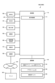
- the figure which shows an example of the functional structure of the terminal which concerns on an Example. 4 is a flowchart showing an example of the flow of processing executed by the terminal according to the embodiment;
- FIG 4 is a flowchart showing an example of the flow of processing executed by a terminal and a server according to an embodiment;
- FIG. 4 is a diagram showing an example of a recording medium
- FIG. 10 is a diagram showing time-series data of fatigue level displayed on the terminal
- FIG. 2 is a diagram showing a configuration example of a terminal
- FIG. 11 is a diagram illustrating a configuration example of another terminal
- FIG. 1 is a block diagram showing an example of a functional configuration of an image processing device 1 according to one aspect of the present embodiment.
- the image processing apparatus 1 includes, for example, a first area detection unit 11, a first color information calculation unit 12, a second area detection unit 13, a second color information calculation unit 14, a color relative information calculation unit 15, and an output unit 16.
- These are, for example, functional units (functional blocks) possessed by a processing unit (processing device) and a control unit (control device) (not shown) of the image processing apparatus 1, and include processors such as CPUs and DSPs and integrated circuits such as ASICs. can be configured to have
- the first area detection unit 11 has a function of detecting a first area in an image captured by an imaging unit (not shown) based on the captured image.
- the captured image may be a captured image captured by any camera.
- the captured image may be an image captured by a front camera, for example, although details will be described later in an embodiment.
- a front camera is a camera that allows a photographer to check himself/herself with a display unit (not shown) when photographing. ) can be provided as a camera (in-camera).
- the captured image may be a captured image captured by a rear camera.
- a rear camera is a camera in which the photographer cannot confirm himself/herself by a display unit (not shown) when photographing. It can be a camera (back camera, out camera) provided on the opposite side of the surface where the camera is facing).
- the first color information calculation unit 12 calculates, for example, hue (Hue)/saturation (Saturation) values defined in the HSL color space based on the image information in the first region detected by the first region detection unit 11, for example. ⁇ It has a function to calculate color information represented by brightness.
- the second area detection unit 13 has a function of detecting the second area in the captured image based on the captured image.
- the second color information calculation unit 14 has a function of calculating, for example, color information defined by the above HSL color space based on image information in the second area detected by the second area detection unit 13. .
- the first area detection unit 11 can detect the first area from the captured image, for example, using an area set in advance by the user or specified by a program as the first area. The same applies to the second area detection section 13 as well. Specific examples of the first area and the second area will be described later.
- the color relative information calculation unit 15 calculates the relative relationship between the first color information calculated by the first color information calculation unit 12 and the second color information calculated by the second color information calculation unit 14, for example. It has a function of calculating color relative information, which is information about.
- the color relative information can include color difference, which is the color distance based on the first color information and the second color information.
- the color difference is a scalar value, and can be calculated, for example, as a Euclidean distance from the first color information and the second color information.
- the color relative information may include a color relative vector represented by a vector in addition to or instead of the color difference.
- the color relative vector can be calculated, for example, as a difference vector between the three-dimensional (for example, components of the HSL color space) first color information and the three-dimensional second color information.
- the output unit 16 has a function of outputting the color relative information calculated by the color relative information calculation unit 15 .
- a memory for accumulating and storing the color relative information calculated by the color relative information calculating unit 15 is provided inside or outside the image processing apparatus. It can be stored in chronological order. Then, the output unit 16 can output, for example, relative information stored in the memory for a plurality of captured images captured at different timings in chronological order.
- first area detection unit 11 and the second area detection unit 13 have the same function (when an image is input, an image obtained by detecting (extracting) a specific area in the image is output). It may be configured as a single area detection unit having
- the first color information calculation unit 12 and the second color information calculation unit 14 are a single color information calculation unit having the same function (function of outputting color information when an image is input). may be configured.
- the first area and the second area can be, for example, two different areas included in the captured image. Also, although this is only an example, the first area and the second area can be, for example, different areas of the same subject included in the captured image (different areas included in the same subject).
- the first color information in the first region and the second color information Relative information (color relative information) relating to the relative relationship with the second color information in the area is calculated. Then, from the calculated relative information, it is possible to analyze how much the color of the first area deviates from the color of the second area. For the same object, it can be assumed that the influence of light due to the imaging environment or the like is the same or similar. For this reason, it can be said that the color relative information is information that is not or hardly affected by the imaging environment or the like.
- FIG. 2 is a diagram showing time-series changes in color difference when color difference is used as the color relative information output from the output unit 16.
- the horizontal axis is the time axis (t) and the vertical axis is the color difference.
- the color difference is illustrated as a graph of a continuous curve. The closer the color difference is to zero, the closer the color of the first area is to the color of the second area. Conversely, the more the color difference is away from zero, the more the color of the first area is deviated from the color of the second area. This application is described briefly below and in detail later in the examples.
- the subject may be, for example, an animal including humans (person, person, person) (here, humans are also included in animals).
- a case in which a person is the subject is exemplified.
- the first area and the second area can be different areas of the same person included in the captured image, for example.
- the first area is, for example, It can be one or both of - face area - neck area.
- the second area is, for example, - It can be the area on the inside of the arm. It should be noted that the arm refers to the area from the shoulder to the wrist.
- the face region is ⁇ It can be the area of the cheek.
- the area inside the arm for example, It can be one or both of - the inner region of the upper arm (upper arm) - the inner region of the wrist.
- the combination of the first region and the second region can be any combination of the above.
- the side closer to the shoulder is referred to as the "upper arm (upper arm)", and the side closer to the hand is referred to as the "forearm”.
- the inside of the arm is considered to be less likely to get sunburned (skin color is less likely to change).
- the inside of the forearm may also get sunburned if you wear short-sleeved clothes. Therefore, the inner side of the upper arm (upper arm) may be used as the inner side of the arm.
- the wrist since the wrist may be less susceptible to sunburn, even the forearm may be used on the inside of the wrist.
- the color of the inside of the upper arm and the inside of the wrist is the ideal skin color (the color of the skin before being affected by disturbance such as sunlight), and the inside of the upper arm and the wrist It is possible to analyze how much the color of the face (cheek) and neck, which are easily affected by sunlight, deviates from the inner color of the color by the above color relative information. Due to the recent trend of sales of beautifying cosmetics, for example, not only the human face (cheek) region but also the human neck region may be targeted for skin beautification such as anti-aging.
- the face area may be an area other than the cheek.
- the subject is not limited to humans, and may be animals other than humans.
- the object is not limited to an animal and may be an object.
- the target is not limited to the different first and second regions among the regions of the same subject included in the captured image, for example, any different first and second regions included in the captured image It is also possible to calculate the color relative information with respect to and analyze how much the colors diverge from each other. For example, a partial area of one subject may be set as a first area, and a partial area of another subject may be set as a second area, and it may be possible to analyze how much the colors diverge.
- FIG. 3 is a flow chart showing an example of image processing procedures in this embodiment.
- the processing shown in the flowchart of FIG. 3 is performed by, for example, a processing unit (not shown) of the image processing apparatus 1 reading an image processing program code stored in a storage unit (not shown) into a RAM (not shown) and executing the code. Realized.
- FIG. 1 shows the storage unit excluded from the components of the image processing device 1, the storage unit may be included in the components of the image processing device 1.
- the image processing device 1 determines whether or not a captured image has been input (A1). If it is determined that the input has been made (A1: YES), the first area detection unit 11 performs processing for detecting the first area from the input captured image (A3). In this process, the first area detection unit 11 performs, for example, area extraction processing to detect the first area.
- the first area can be detected using a key point detection technique. Semantic segmentation may also be performed on captured images using techniques such as FCN (Fully Convolutional Network), SegNet, and U-Net, which are one technique of deep learning. Then, the position of the pixel classified as the first region and the color information of the pixel are used as the extraction result. For example, if the first region is the cheek region, the extraction result is the position of the pixel classified as the cheek region and the color information of the pixel.
- FCN Full Convolutional Network
- SegNet SegNet
- U-Net which are one technique of deep learning.
- HOG Heistogram of Oriented Gradients
- SVM Serial Vector Machine
- skin color likeness may be evaluated for the extraction result by SVM.
- region extraction may be performed by combining the result of deep learning and these results.
- the second area detection unit 13 detects the second area from the captured image (A5). This can also be realized, for example, by the area extraction process similar to that described above. For example, if the second region is the inner region of the upper arm or the inner region of the wrist, the positions of the pixels classified as these regions by Key Point Detection, semantic segmentation methods, etc. and the color information of the pixel are extracted results.
- the image processing apparatus 1 may collectively execute the extraction of the first region and the extraction of the second region, for example, based on the result of semantic segmentation.
- the image processing apparatus 1 determines whether or not the detection of the first area and the second area has succeeded (A7).
- This determination is, for example, based on the detection result (extraction result) of A3 to determine whether or not the first region occupies a set ratio of the captured image, and based on the detection result (extraction result) of A5, the second region is determined. It can be realized by determining whether or not it occupies a set proportion of the captured image.
- A7 may be determined by determining whether or not the first area and the second area occupy a set proportion of the captured image.
- the image processing apparatus 1 If it is determined that at least one detection has failed (A7: NO), the image processing apparatus 1 returns the process to A1. In this case, the image processing apparatus 1 may return the processing to A1 after performing some error processing. Since there is a possibility that there is a problem with the imaging, it is also possible to output information to call the user's attention to that effect.
- the first color information calculation unit 12 calculates the first color information based on the detection result of A3 (A9). For example, the average value of the color information of each pixel is calculated for each image patch (small area of an image) of a set size. Then, based on the average value, for example, color information (first color information) for each image patch in a predetermined color space is calculated.
- the second color information calculation unit 14 calculates the second color information based on the detection result of A5 (A11). This approach can be similar to A9, for example.
- the color relative information calculator 15 calculates color relative information based on the first color information calculated in A9 and the second color information calculated in A11 (A13). For example, if a color difference is to be calculated as color relative information, the color relative information calculator 15 calculates the Euclidean distance between the first color information calculated in A9 and the second color information calculated in A11. to calculate the color difference. Further, for example, if a color relative vector is to be calculated as the color relative information, the color relative information calculation unit 15 calculates the three-dimensional color information calculated in A9 and the three-dimensional color information calculated in A11. Calculate the vector of differences (three dimensions).
- the image processing apparatus 1 determines whether or not the conditions for outputting color relative information are satisfied (A15). If it is determined that the output condition is not met (A15: NO), the image processing apparatus 1 returns the process to A1. On the other hand, if it is determined that the output condition is satisfied (A15: YES), the image processing apparatus 1 terminates the process.
- Output conditions include, for example, outputting each captured image, calculating color relative information for a set number of captured images, calculating color relative information for captured images for a set period, and the like. , various conditions can be defined.
- the image processing apparatus 1 When calculating the color relative information for a set number of captured images, the image processing apparatus 1 outputs, for example, the average value or the median value of each color relative information calculated for each captured image. may The same applies to the calculation of color relative information for captured images for a set period. That is, the image processing apparatus 1 may output one piece of color relative information from a plurality of captured images. By outputting one piece of color relative information from a plurality of captured images, it is expected that the influence of the imaging environment can be reduced.
- step A5 is executed after step A3, but this order may be reversed. The same applies to steps A9 and A11.
- Example 1 An example of a terminal to which the image processing device 1 described above is applied or provided with the image processing device 1 described above will be described.
- the terminal can be, for example, a terminal device possessed by the user, such as a mobile phone including a smart phone, a camera, a PDA, a personal computer, a navigation device, a wrist watch, and various tablet terminals.
- a smart phone which is a type of mobile phone with a camera function (with an imaging function)
- the terminal 100 is illustrated and described.
- embodiments to which the present disclosure can be applied are not limited to the embodiments described below.
- FIG. 4 is a diagram showing an example of a functional configuration of a terminal 100A, which is an example of the terminal 100, which is a smart phone in this embodiment.
- the terminal 100 includes, for example, a processing unit 110, an operation unit 120, a touch panel 125, a display unit 130, a sound output unit 140, an imaging unit 150, an environment information detection unit 160, a clock unit 170, and a communication unit. 180 and a storage unit 190 .
- the processing unit 110 is a processing device that comprehensively controls each unit of the terminal 100 according to various programs such as a system program stored in the storage unit 190 and performs various processes related to image processing. processor and an integrated circuit such as an ASIC.
- the processing unit 110 includes, for example, a first area detection unit 111, a second area detection unit 112, a first color information calculation unit 113, a second color information calculation unit 114, a color difference calculation unit 115, and a display control unit. 116.
- the first area detection unit 111 to the second color information calculation unit 114 correspond to the first area detection unit 11 to the second color information calculation unit 14 described above.
- the color difference calculation unit 115 is a type of the color relative information calculation unit 15 described above, and calculates the color difference between the first color information and the second color information.
- the display control unit 116 controls the display unit 130 to display the color difference information calculated by the color difference calculation unit 115 and output in time series.
- the transmission of color relative information (color difference in this example) to each functional unit in order for the processing unit 110 to perform various controls (display control, sound output control, communication control, etc.) is regarded as output.
- the output unit 16 of the image processing apparatus 1 may be regarded as the processing unit 110 including the display control unit 116 . Further, for example, the output unit 16 of the image processing apparatus 1 in FIG. 1 may be regarded as functional units such as the display unit 130, the sound output unit 140, the communication unit 180, and the like.
- the operation unit 120 includes input devices such as operation buttons and operation switches for the user to perform various operational inputs to the terminal 100 .
- the operation unit 120 also has a touch panel 125 integrated with the display unit 130 , and the touch panel 125 functions as an input interface between the user and the terminal 100 .
- An operation signal according to a user's operation is output from the operation unit 120 to the processing unit.
- the display unit 130 is a display device that includes an LCD (Liquid Crystal Display) or the like, and performs various displays based on display signals output from the display control unit 116 .
- the display unit 130 is integrated with the touch panel 125 to form a touch screen.
- the sound output unit 140 is a sound output device including a speaker or the like, and performs various sound outputs based on sound output signals output from the processing unit 110 .
- the imaging unit 150 is an imaging device configured to be able to capture an image of any scene, and has an imaging element (semiconductor element) such as a CCD (Charge Coupled Device) image sensor or a CMOS (Complementary MOS) image sensor. Configured.
- the imaging unit 150 forms an image of light emitted from an object to be imaged on a light-receiving plane of an imaging element by a lens (not shown), and converts the brightness of the light of the image into an electric signal by photoelectric conversion.
- the converted electric signal is converted into a digital signal by an A/D (Analog Digital) converter (not shown) and output to the processing section.
- the imaging unit 150 is arranged, for example, on the side of the terminal 100 where the touch panel 125 exists. You may call it a front camera.
- the imaging unit 150 may be configured as an imaging unit (rear camera) that is arranged on the rear surface of the terminal 100 where the touch panel 125 does not exist and has a flash (strobe) that can be used as a light source during imaging.
- This flash may have a known color temperature when it is emitted, or may be a flash whose color temperature is dimmable by the processor.
- the display control unit 116 may cause the display unit 130 to display a live view image at the time of imaging by these imaging units.
- the environment information detection unit 160 detects information about the environment of its own device (hereinafter referred to as "environment information").
- Environmental information can include, for example, temperature and/or humidity.
- the clock unit 170 is a built-in clock of the terminal 100 and outputs time information (clock information).
- the clock unit 170 includes, for example, a clock using a crystal oscillator.
- the clock unit 170 may be configured with a clock to which the NITZ (Network Identity and Time Zone) standard or the like is applied.
- NITZ Network Identity and Time Zone
- the communication unit 180 is a communication device for transmitting and receiving information used inside the device to and from an external information processing device.
- As the communication method of the communication unit 180 there is a form of wired connection via a cable conforming to a predetermined communication standard, a form of connection via an intermediate device that is also used as a charger called a cradle, and a wireless communication system. Various methods such as the form of connection can be applied.
- the storage unit 190 is a storage device that includes a volatile or nonvolatile memory such as ROM, EEPROM, flash memory, and RAM, a hard disk device, and the like.
- the storage unit 190 stores, for example, a color information processing program 191, a color difference calculation processing program 193, an image buffer 195, and color difference history data 197.
- the color information processing program 191 is a program read by the processing unit 110 and executed as color information processing.
- the color difference calculation processing program 193 is a program read by the processing unit 110 and executed as color difference calculation processing.
- the image buffer 195 is, for example, a buffer in which captured images captured by the imaging unit 150 are stored.
- the color difference history data 197 is, for example, data in which the color difference calculated by the color difference calculation unit 115 is stored in association with the date and time (or time) measured by the clock unit 170 .
- a gyro sensor or the like that detects angular velocities around three axes may be provided.
- FIG. 5 is a flow chart showing an example of the flow of color information processing executed by the processing unit 110 of the terminal 100A in this embodiment.
- the processing unit 110 determines whether or not an image has been captured by the image capturing unit 150 (B1).
- the color difference calculation unit 115 performs color difference calculation processing (B3). Specifically, based on the processing illustrated in FIG. 3 and the like, the color difference is calculated as the color relative information for the captured image.
- the processing unit 110 stores the calculated color difference in the color difference history data 197 in association with the clock information (date and time, etc.) of the clock unit 170 (B5).
- the processing unit 110 acquires data of a plurality of captured images by the imaging unit 150, and calculates color relative information (color difference) based on the data of the plurality of captured images stored in the image buffer 195.
- the processing unit 110 determines whether or not to display the color difference history information (B7). Specifically, for example, it is determined whether or not the user has made an input to display the color difference history information via the operation unit 120, the touch panel 125, or the like. If it is determined to display the color difference history information (B7: YES), the processing unit displays the color difference history information on the display unit 130 based on the color difference history stored in the color difference history data 197 (B9).
- the processing unit 110 determines whether or not to end the processing, and if it determines to continue the processing (B11: NO), returns the processing to B1. On the other hand, if it is determined to end the processing (B11: YES), the processing unit 110 ends the processing.
- the processing unit 110 advances the process to B7. If it is determined not to display the color difference history information (B7: NO), the processing unit 110 advances the process to B11.
- the terminal 100A may display the color difference in association with the imaging date and time of the imaging unit 150 based on the clock information of the clock unit 170 .
- the terminal 100A may display the color difference and the environment information detected by the environment information detection unit 160 in association with each other. More specifically, using the detection result of the environment information detection unit 160 at the date and time corresponding to the date and time of imaging by the imaging unit 150, the color difference and the environment information are displayed in association with the date and time. You may do so. Either one of temperature and humidity information may be displayed as environment information. Also, the environment information may be acquired from an environment information providing server (not shown) via the communication unit 180 .
- a color relative vector may be calculated and displayed as color relative information.
- a color relative vector may be displayed with an arrow in the color space.
- the server can be, for example, a server that communicates with the terminal of the user described above (eg, a server in a client-server system).
- the skin analysis application may be an application that is downloaded from a server, stored in the storage unit of the terminal, and executed, or an application that is executed without being downloaded (for example, a web application).
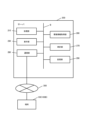
- FIG. 6 is a diagram showing an example of a functional configuration of a terminal 100B, which is an example of the terminal 100 in this embodiment.
- the same components as those of the terminal 100A shown in FIG. 4 are denoted by the same reference numerals, and repeated explanations are omitted.
- the processing unit 110 of the terminal 100B has, for example, the above-described display control unit 116 as a functional unit.
- the communication unit 180 of the terminal 100B communicates via the network 300 with the server 200 that manages various information regarding the skin analysis application.
- the storage unit 190 of the terminal 100B stores, for example, a skin analysis application processing program 192 read by the processing unit 110 and executed as skin analysis application processing, the terminal 100B using the skin analysis application, Alternatively, the application ID 194, which is information relating to the account of the user of the terminal 100B, and the image buffer 195 described above are stored.
- the terminal 100B may not include the environment information detection unit 160 and may acquire the environment information from the server 200, for example.
- FIG. 7 is a diagram showing an example of the functional configuration of the server 200 in this embodiment.
- the server 200 includes, for example, a processing unit 210, a display unit 230, an environment information acquisition unit 260, a clock unit 270, a communication unit 280, and a storage unit 290, which are connected via a bus B. .
- the HW configuration of the processing unit 210, the display unit 230, the clock unit 270, the communication unit 280, and the storage unit 290 can be the same as that of the terminal 100, so description thereof will be omitted.
- the environment information acquisition unit 260 acquires environment information detected by an environment information detection unit (temperature sensor, humidity sensor, etc.) provided in the device itself, or an environment information providing server (not shown) that provides the environment information. Get environment information from .
- the communication unit may be the environment information acquisition unit.
- the communication unit 280 transmits and receives information (data) to and from other devices including the terminal 100B via the network 300.
- the storage unit 290 stores, for example, the terminal 100B that uses the skin analysis application or management data related to the user of the terminal 100B. Further, in the storage unit 290, for example, for each application ID, color difference history data in which the color difference is stored in association with the clock information of the clock unit 270 is stored as a database.
- the server 200 may not include the environment information acquisition unit 260, and acquire environment information from the terminal 100B.
- FIG. 8 is a flow chart showing an example of the flow of processing executed by each device in this embodiment.
- the left side shows an example of the skin analysis application processing executed by the processing unit 110 of the terminal 100B
- the right side shows an example of management processing related to the skin analysis application executed by the processing unit 210 of the server 200.
- the processing unit 110 of the terminal 100B determines whether or not an image has been captured by the imaging unit 150 using the skin analysis application (C1). Then, if it is determined that an image has been captured (C1: YES), the processing unit 110 of the terminal 100B sends the captured image data including the application ID 194 stored in the storage unit 190 and the captured image data to the communication unit 180. to the server 200 (C3). Note that the processing unit 110 of the terminal 100B may repeat image capturing by the image capturing unit 150 and transmit captured image data including data of a plurality of captured images.
- the processing unit 210 of the server 200 determines whether or not the imaging data has been received from the terminal 100B by the communication unit 280 (S1). According to a color difference calculation processing program (not shown), a process of calculating, for example, the color difference between the first color information and the second color information is performed from the imaged image included in the imaged data received from the terminal 100B (S3). Then, the processing unit 210 of the server 200 associates the calculated color difference with the clock information (date and time, etc.) of the clock unit 270, and stores it as color difference history data corresponding to the application ID included in the received imaging data (S5). .
- the processing unit 110 of the terminal 100B determines whether or not to display the color difference history information by the skin analysis application (C5). Specifically, for example, the skin analysis application determines whether or not the user has made an input to display the color difference history information via the operation unit 120, the touch panel 125, or the like. If it is determined to display the color difference history information (C5: YES), the processing unit 110 of the terminal 100B, for example, displays the color difference history information including the application ID 194 stored in the storage unit 190 and information requesting display of the color difference history information. A history information display request is made to the server 200 by the communication unit 180 (C7).
- the processing unit 210 of the server 200 determines whether or not there is a request for display of color difference history information from the terminal 100B (S7). Based on the received color difference history data corresponding to the application ID 194, for example, the communication unit 280 transmits color difference history information including the color difference history for the set period to the terminal 100B (S9).
- the processing unit 110 of the terminal 100B causes the skin analysis application to display the received color difference history information on the display unit 130 (C9).
- the processing unit 110 of the terminal 100B determines whether or not to end the processing (C11), and if it determines to continue the processing (C11: NO), returns the processing to C1. On the other hand, if it is determined to end the processing (C11: YES), the processing unit 110 of the terminal 100B ends the processing of the skin analysis application.
- the processing unit 210 of the server 200 determines whether or not to end the process (S11), and if it determines to continue the process (S11: NO), returns the process to S1. On the other hand, if it is determined to end the process (S11: YES), the processing unit 210 of the server 200 ends the process.
- the processing unit 110 of the terminal 100B advances the process to C5. If it is determined not to display the color difference history information (C5: NO), the processing unit 110 of the terminal 100B advances the process to C11.
- the processing unit 210 of the server 200 advances the process to S7. If it is determined that there is no color difference history information display request (S7: NO), the processing unit 210 of the server 200 advances the process to S11.
- each terminal 100 that uses the skin analysis application can perform the same process.
- the server 200 can perform similar processing for each terminal 100 .
- a color relative vector may be calculated and displayed as color relative information.
- a color relative vector may be displayed with an arrow in the color space.
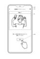
- FIG. 9 is a diagram showing an example of a skin analysis application screen displayed on the display unit 130 of the terminal 100 in this embodiment.
- This screen is a diagram showing an example of a navigation screen displayed when the user inputs to activate the imaging unit 150 in the skin analysis application (B1 in FIG. 5, C1 in FIG. 8).
- Step. 1 is displayed along with a navigation area R1 for illustrating how to take an image.
- This illustration shows a woman holding the terminal 100 with her right hand and raising her opposite arm to take a picture.
- the text "Please shoot so that the inside of the cheek and upper arm fits" is displayed, and below that is an "OK" button to proceed to the next screen.
- BT1 is displayed.
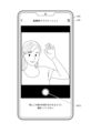
- FIG. 10 is a diagram showing an example of an imaging screen for the user to take an image with the skin analysis application. are placed.
- FIG. 9 the text "Please shoot so that the inside of the cheeks and the upper arm is covered” is displayed.
- the user can take the pose shown in FIG. 9 and press the imaging button BT3 to cause the imaging section 150 to perform imaging.
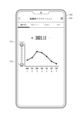
- FIG. 11 is a diagram showing an example of a color difference history information display screen that is displayed when the user inputs to display color difference history information in the skin analysis application (B9 in FIG. 5, C5 in FIG. 8: YES ⁇ C9).
- This screen shows a state in which a "skin graph" tab is tapped among tabs including a plurality of functions that can be used by the user in the skin analysis application provided at the top of the screen.
- a history of color differences during a past predetermined period in this example, the period from "November 1, 2021" to "November 7, 2021" is displayed in a graph.
- the user takes pictures every day during the period of seven days, and the change in color difference for each day is displayed in a graph (in this example, a line graph) with the date on the horizontal axis and the color difference on the vertical axis.
- a graph in this example, a line graph
- the display is not limited to the line graph, and may be displayed as a bar graph or the like. Alternatively, the numerical values themselves may be displayed instead of the graphs.
- the characters "skin tone" are displayed in association with the vertical axis.
- a defect icon IC1 in this example, an icon of a face that is not smiling
- a skin icon IC1 is displayed on the side of the lower part of the vertical axis.
- a good icon IC2 in this example, a smiling icon
- a plurality of lower triangular marks are displayed to indicate that the skin condition is gradually improving from the defective icon IC1 toward the good icon IC2.
- the region of the user's cheek is the determination target region (measurement target region). Also, the area inside the user's upper arm is set as a comparison target area. Then, the aforementioned processing is performed with the region of the user's cheek as the first region and the region of the user's upper arm as the second region.
- the inside of the upper arm is less likely to be affected by disturbances such as sunlight, and it is thought that the color of the skin is likely to be maintained. Therefore, in this example, the color of the inside of the upper arm is set as the user's target skin color (ideal value). In other words, the color of the inner region of the upper arm is used as a whitening benchmark. Based on the captured image captured by the user, how much the color of the user's cheek deviates from the color of the inner side of the upper arm is reported to the user using the color difference as an index value. According to the above, it can be considered that the smaller the color difference, the closer the user's cheek color is to the ideal value. Conversely, it can be considered that a larger color difference indicates that the user's cheek color is farther from the ideal value.
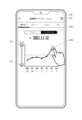
- FIG. 12 is a diagram showing another example of the color difference history information display screen of FIG.
- time-series graphs of temperature and humidity are displayed as environment information in association with the time-series graph of color difference in the graph shown in FIG. That is, the color difference information and the environment information are displayed in correspondence with each other in timing.
- the user can compare the time-series color difference and the time-series temperature and humidity. It is possible for the user to analyze in what kind of environment the skin condition tends to deteriorate. Either one of temperature and humidity information may be displayed as environment information.
- the processing unit 210 of the server 200 may transmit the environment information acquired by the environment information acquisition unit 260 to the terminal 100 together with the time-series color difference information. can be done.
- the server 200 based on the information on the area where the user is registered in advance and the information on the location of the terminal 100 transmitted from the terminal 100, stores the environment information for the area and the location of the terminal 100. may be acquired and transmitted to the terminal 100 . That is, in this example, the terminal 100 can acquire environment information from the server 200 .
- the server 200 receives imaging data including environment information from the terminal 100 (C3 in FIG. 8, S1: YES), and stores the environment information received from the terminal 100 in the storage unit 290. You can leave it as is. Then, information that associates the color difference history information and the environment information may be transmitted to the terminal 100 (S9 in FIG. 8).
- the terminal calculates the first color information in the first area included in the captured image and the second color information in the second area included in the captured image. Then, the terminal calculates color relative information (an example of relative information regarding a relative relationship) between the calculated first color information and second color information. Then, the terminal outputs time-series color differences for a plurality of captured images captured at different timings. Accordingly, the terminal can calculate relative information regarding the relative relationship between the first color information in the first area included in the captured image and the second color information in the second area included in the captured image. In addition, time-series relative information can be output for a plurality of captured images captured at different timings.
- the relative color information can be, for example, color difference information. This allows the terminal to output time-series color difference information for a plurality of captured images captured at different timings.
- the first area and the second area can be different areas of the same subject. Accordingly, it is possible to calculate color relative information based on color information of different regions of the same subject.
- the second area can be used as a comparison target area, and can be used as a criterion for determining how much the color of the first area of the same subject deviates from the color of the second area of the same subject.
- the first area can be a face area. This can be used as a criterion for determining how much the color of the face area of the same subject deviates from the color of the area different from the face area of the same subject.
- the first region can be the cheek region. This can be used as a criterion for determining how much the color of the cheek region of the same subject deviates from the color of the region different from the face region of the same subject.
- the first region can be the neck region. This can be used as a criterion for determining how much the color of the neck region of the same subject deviates from the color of the region different from the neck region of the same subject.
- the second region can be the inner region of the arm. This can be used as a criterion for determining how much the color of the area different from the inner side of the arm of the same subject deviates from the color of the inner side of the arm of the same subject.
- the second region can be the inner region of the upper arm or the inner region of the wrist. This can be used as a criterion for determining how much the color of the area different from the inner area of the upper arm of the same subject deviates from the color of the inner area of the arm of the same subject. In addition, it can be used as a criterion for determining how much the color of the region different from the region on the inside of the wrist of the same subject deviates from the color of the region on the inside of the wrist of the same subject.
- the user's terminal includes any of the above image processing devices, an imaging unit 150 that captures the above captured image, and a display unit 130 that displays color relative information. be able to. Thereby, the relative information calculated based on the captured image captured by the imaging unit can be displayed on the display unit so that the user can recognize it.
- the display unit 130 can display the color relative information in association with the information of the imaging date and time and the imaging time (an example of the information that can specify the timing). This allows the user to recognize the relative information as well as the timing at which the image was captured. Since it becomes possible to refer to the timing at which the image was captured, the user's convenience can be improved.
- the user's terminal further includes an environment information detection unit 160 and a communication unit 180 (an example of an environment information acquisition unit that acquires environment information) that receives environment information from the server.
- Information and environment information can be displayed in association with each other. This allows the user to recognize the relative information together with the acquired environmental information. Since the environment information can be referred to, the user's convenience can be improved.
- the server calculates the first color information in the first area included in the captured image and the second color information in the second area included in the captured image. . Then, the server calculates color relative information (an example of relative information regarding a relative relationship) between the calculated first color information and second color information. Then, the server outputs time-series color differences for a plurality of captured images captured at different timings. Thereby, the server can calculate the relative information regarding the relative relationship between the first color information in the first area included in the captured image and the second color information in the second area included in the captured image. In addition, time-series relative information can be output for a plurality of captured images captured at different timings.
- the server includes any one of the image processing apparatuses described above, and a communication unit that receives the captured image from the terminal and transmits the calculated relative information to the terminal.
- the server can acquire the captured image from the terminal, calculate the relative information based on the captured image, and transmit the relative information to the terminal. From the viewpoint of the terminal side, the processing load can be reduced because the terminal only needs to transmit the captured image to the server and does not need to perform calculations.
- no makeup mode a mode in which an image is taken without makeup
- foundation mode a mode in which an image is taken with foundation applied
- the user can select "no makeup mode” or "foundation mode” before the screen shown in FIG. 9 is displayed or within the screen shown in FIG. Configure the user interface (UI). Then, when the "no makeup mode” is selected, the user without makeup is imaged on the imaging screen of FIG. Further, when the "foundation mode” is selected, it is possible to take an image on the imaging screen of FIG. 10 while the user is applying foundation.
- the terminal 100 may notify the user based on the color relative information.
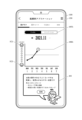
- FIG. 13 is a diagram showing an example of the color difference history information display screen displayed on the display unit 130 of the terminal 100 in this embodiment.
- the view of the screen is the same as in FIG.
- a case in which different notification contents are notified in the two modes of "no makeup mode” and “foundation mode” described in "(1) mode” will be exemplified.
- a mode switching tab MT1 is provided that includes a tab for displaying information and a tab for displaying color difference history information based on an image captured in the “foundation mode”. Then, in this example, when the user taps the "no makeup mode” tab of the mode switching tabs MT1, the "no makeup mode” tab is displayed in reverse video, and the "no makeup mode” tab is displayed below. The history information of the color difference created is displayed.
- the time-series color difference graph shows a case where the color difference exceeds or exceeds a set value (threshold value).
- a state in which the color difference calculated based on the captured image captured on "November 3, 2021" is greater than or equal to the set value is shown.
- a caution mark MK1 is displayed next to the color difference value. When the caution mark MK1 is tapped by the user, for example, a screen as shown in FIG. 14 is displayed.
- an area in which the notification information sent from the server is displayed is configured under the area in which the graph is displayed.
- the text "Your skin is not very good. It's dry and it's prone to rough skin.”
- Information is displayed, including text telling the user the points to be made, and an "OK" button for hiding these displays.
- the notification information for the user is displayed on the display unit 130 based on the fact that the color difference satisfies the setting condition that the color difference becomes equal to or greater than the first set value or exceeds the first set value.
- notification information information for alerting the user that the second color information is ideal and the first color information deviates from the ideal, more specifically, alerting the user to the condition of the skin. (information for notifying the user that the skin condition is not good) is displayed.
- notification information is displayed for the user based on the setting condition that the color difference is less than the second set value or equal to or less than the second set value is satisfied. It may be displayed in section 130 .
- the second set value can be set as a value smaller than the first set value.
- notification information information that informs the user that the second color information is ideal and that the first color information is close to ideal, more specifically, informs the user that the skin condition is good. Information to be notified may be displayed.
- notification information may be displayed by a balloon, bubble, or the like based on the caution mark MK1 and the value of the color difference attached to the caution mark MK1.
- the notification information may be displayed without displaying the caution mark MK1.
- the notification described above is not limited to being displayed, and may be realized by outputting sound (including voice) from the sound output unit 140 .
- the notification information may be sound information (including voice information).
- the sound output unit 140 may output a caution sound or an alerting announcement based on the setting condition that the color difference is equal to or greater than the first set value or exceeds the first set value.
- the alert announcement may have the same content as the text shown in FIG. 14, or may have different content.
- a fanfare sound or a congratulatory announcement may be output from the sound output unit 140 based on the setting condition that the color difference is less than the second set value or equal to or less than the second set value is satisfied.
- the mode switching tab MT1 can be dispensed with.
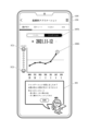
- FIG. 15 is a diagram showing an example of the color difference history information display screen displayed on the display unit 130 of the terminal 100 in this embodiment. On this screen, when the user taps the foundation mode tab of the mode switching tabs MT1, the foundation mode tab is highlighted, and the color difference history information in the foundation mode is displayed below it. .
- an area where the notification information sent from the server is displayed is configured below the area where the graph is displayed.
- a region R5 represented by a balloon from the illustration of an angel at the bottom of the screen similar to that in FIG. a text telling the user what to pay attention to, and an "OK" button for hiding these displays.
- the notification content is different from the "no makeup mode” in FIG. 14, and the notification information corresponding to the "foundation mode” is displayed.
- the notification information for the user is displayed on the display unit 130 based on the fact that the color difference calculated in the "foundation mode" satisfies the setting condition that the third setting value or more or the third setting value is exceeded. is displayed in Specifically, as notification information, information for alerting the user that the second color information is ideal and the first color information deviates from the ideal, more specifically, for example, foundation (foundation color) Information or the like is displayed to call attention that the values do not match.
- the color difference calculated in the "foundation mode" is less than the fourth set value, or the setting condition is satisfied that the fourth set value or less is satisfied.
- notification information for the user may be displayed on the display unit 130 .
- the fourth set value can be set as a value smaller than the third set value.
- notification information information informing the user that the second color information is ideal and the first color information is close to ideal. Information may be displayed to notify the user of the existence of the device.
- notification information may be displayed by a balloon, bubble, or the like based on the caution mark MK1 and the value of the color difference attached to the caution mark MK1.
- the notification information may be displayed without displaying the caution mark MK1.
- the notification described above is not limited to being displayed, and may be realized by outputting sound (including voice) from the sound output unit 140 .
- the notification information may be sound information (including voice information).
- the sound output unit 140 may output a caution sound or an alert announcement based on the setting condition that the color difference is equal to or greater than the third set value or exceeds the third set value.
- the alert announcement may have the same content as the text shown in FIG. 16, or may have different content.
- a fanfare sound or a congratulatory announcement may be output from the sound output unit 140 based on the setting condition that the color difference is less than the fourth set value or equal to or less than the fourth set value is satisfied.
- the "no makeup mode” tab of the mode switching tab MT1 shown in the above display screen When the user taps the "no makeup mode” tab of the mode switching tab MT1 shown in the above display screen, the "no makeup mode” tab is highlighted, and the color difference history information in the "no makeup mode” is displayed. can be made visible. Further, in this case, for example, a screen as shown in FIG. 14 described above is displayed, and if the caution mark MK1 is included in the screen, for example, based on the tapping of the caution mark MK1, the screen shown in FIG. A screen such as 15 can be displayed.
- the content to be notified (notification information) can be stored in the storage unit of the terminal 100 or the server 200 in a database in association with the setting value, for example. Then, depending on which set value the color difference satisfies the threshold condition based on, the corresponding notification information can be read from the database and the notification information can be displayed.
- the color difference history information of the "no makeup mode” and the color difference history information of the "foundation mode” may be displayed (overlaid) in one graph with corresponding timing.
- the environmental information described above may also be displayed (overlaid) with corresponding timing.
- the display unit 130 of the user's terminal displays notification information to the user when the color difference (an example of relative information) satisfies the setting condition.
- the color difference an example of relative information
- the setting condition includes that the color difference is equal to or greater than the first set value or exceeds the first set value, and the notification information is such that the second color information is ideal and the first color information is not ideal. It is possible to include information for alerting the user of the divergence. Accordingly, when the color difference is a value that is large to some extent, it is possible to alert the user that the first color information deviates from the ideal.
- the notification information can include information for alerting the user to the condition of the user's skin.
- the notification information can include information for alerting the user to the condition of the user's skin.
- the setting condition includes that the color difference is less than a second set value that is smaller than the first set value, or that the color difference is less than or equal to a second set value that is smaller than the first set value, and the notification information is Information may be included to notify the user that the second color information is ideal and the first color information is close to ideal. This makes it possible to inform the user that the first color information is close to ideal when the color difference is a relatively small value.
- the notification information can include information for notifying the user that the user's skin condition is good. Accordingly, when the color difference is a relatively small value, it is possible to inform the user that the user's skin condition is good.
- Stepwise notification for example, a stepwise set value is set as a set value, and different notification is made based on which set value the color difference exceeds or exceeds the set value. You may make it alert
- the terminal will display the message "Your skin condition is getting worse. to display notification information that calls attention to
- the color difference is greater than or equal to a set value B which is larger than the set value A (or exceeds the set value B)
- the terminal outputs notification information alerting that "the skin condition is getting worse.” You may make it display.
- the user of the terminal 100 may be able to set which area is to be processed by inputting settings to the terminal 100 . For example, if the user wants to know the result when the first region is the cheek and the second region is the inside of the wrist, select the cheek as the first region and the inside of the wrist as the second region. may be set by the terminal 100.
- the user selects the neck as the first region and the inner side of the upper arm as the second region. It may be selected and set by the terminal 100 .
- the terminal 100 calculates the color difference
- the terminal 100 detects the first area and the second area set based on the user input as described above from the captured image, and then performs the same processing as described above. can do.
- the server 200 performs processing
- the terminal 100 transmits the setting information of the first area and the second area set based on the user input as described above to the server 200 together with the captured image data, and the server 200 After detecting the first area and the second area included in the received setting information from the captured image, the same processing as described above can be performed.
- the terminal 100 may perform all of the above-described processing without being limited to, for example, performing the processing to which the client-server system is applied.
- the processing of the server 200 shown in FIG. 8 is similarly applied to the color information processing shown in FIG. 5 to which the configuration example of the terminal 100A shown in FIG. A similar process may be performed.
- color information represented by Hue, Saturation, and Lightness defined in the HSL color space was used as color information. is not limited to
- color information displayed in YCbCr may be used.
- color information expressed in RGB may be used.
- Each color system has a mapping relationship.
- YCbCr and RGB can be converted by linear conversion. The same technique as in the above embodiments can be applied to any color system.
- Terminal 100 As the user's terminal 100, as described above, in addition to mobile phones such as smart phones, various devices such as cameras, PDAs, personal computers, navigation devices, wristwatches, and various tablet terminals can be applied. .
- the user's terminal 100 does not necessarily have to include the imaging unit 150 .
- the terminal 100 can acquire captured image data from an external device including the imaging unit 150 and perform the above-described image processing based on the acquired captured image data.
- the storage unit of each device includes internal storage devices such as ROM, EEPROM, flash memory, hard disk, and RAM, as well as memory cards (SD cards), compact flash (registered trademark) cards, memory sticks, USB memories, and CDs.
- ROM read-only memory
- EEPROM electrically erasable programmable read-only memory
- flash memory electrically erasable programmable read-only memory
- RAM random access memory
- FIG. 17 is a diagram showing an example of a recording medium in this case.
- the image processing apparatus 1 is provided with a card slot 410 into which a memory card 430 is inserted.
- a card reader/writer (R/W) 420 is provided for writing information.
- the card reader/writer 420 writes the programs and data recorded in the storage unit to the memory card 430 under the control of the processing unit.
- the programs and data recorded in the memory card 430 are read by an external device other than the image processing apparatus 1, so that the external device can implement the image processing in the above embodiment.
- the above recording medium can also be applied to various devices such as the terminals, servers, electronic devices (electronic devices), color information analysis devices, and information processing devices described in the above embodiments.
- the image processing device 1 may be configured as a device such as a skin analysis device. Further, a device such as a rough skin notification device may be configured as a device including the image processing device 1 and the notification unit described above.
- the technique of calculating color relative information from the first color information and second color information of an image in which the subject is a human being and displaying the color relative information in chronological order can be applied to various monitor methods.
- the technology described above can be applied as a non-contact vital sensing technology for measuring the degree of fatigue of workers.
- a worker is, but not limited to, a person who engages in work in which overwork can lead to an accident. Such workers are, for example, drivers of heavy vehicles.
- FIG. 18 is a diagram showing an example screen of the fatigue measurement application.
- the terminal 100 is a smart phone and has an in-camera 101 and a display unit 130 .
- a worker takes an image of himself/herself with the in-camera 101 every day, for example.
- Color relative information is calculated by the method described above for a plurality of images captured on different dates. The calculated color relative information is displayed in chronological order according to the operation of the terminal operator. In the example of FIG. 18, transition of color relative information from December 5, 2022 to December 11, 2022 is illustrated.
- the color relative information is a color difference or a color relative vector, and the terminal operator is notified that the greater the value, the higher the fatigue level, and the smaller the value, the lower the fatigue level.
- the first threshold TH1 is set as the degree of fatigue at which certain fatigue is recognized
- the second threshold TH2 is set as the degree of fatigue reaching serious fatigue.
- One threshold can be set, or a plurality of thresholds can be set stepwise.
- the degree of fatigue exceeding the first threshold TH1 is detected on December 8th
- the degree of fatigue exceeding the second threshold TH2 is detected on December 9th
- the first threshold TH1 is detected on December 10th.
- a exceeded threshold has been detected.
- the communication function of the terminal 100 is used to notify an external administrator or the like, or the display unit 130 indicates that the degree of fatigue is increasing, so it is recommended to take a rest.
- a prompting message can be displayed, or the message can be read aloud.
- the above-described technology can be used to confirm the effects of esthetics, gyms, health foods, and the like. According to still another example, the above-described technology can be utilized as one of the detection conditions for confirming the intention of a dementia patient or the like.
- the function of generating time-series data of color relative information can be realized by a processing circuit. That is, the processing circuit calculates color information, calculates color relative information, and generates time-series data of the color relative information. Even if the processing circuit is dedicated hardware, it is a CPU (also called Central Processing Unit, central processing circuit, processing unit, arithmetic circuit, microprocessor, microcomputer, DSP) that executes programs stored in memory. good too.
- CPU also called Central Processing Unit, central processing circuit, processing unit, arithmetic circuit, microprocessor, microcomputer, DSP
- the processing circuit may be, for example, a single circuit, a composite circuit, a programmed processor, a parallel programmed processor, an ASIC, an FPGA, or a combination of these.
- FIG. 19 is a diagram showing a configuration example of a terminal.
- the image processing circuit 10B generates data such as JPEG from the data captured by the camera 10A.
- Image data generated by the image processing circuit 10B is provided to the processing circuit 10C.
- the processing circuit 10C generates time-series data of the color relative information described above. Then, the time-series data is displayed on the display 10D according to the terminal user's operation.
- FIG. 20 shows a configuration example when the processing circuit is a CPU.
- each function of the processing circuit is realized by software or a combination of software and firmware.
- Software or firmware is written as a program and stored in the memory 10c.
- the processor 10b implements each function by reading and executing the program stored in the memory 10c. That is, the memory 10c is provided for storing a program that, when executed by the processing circuit of FIG. 20, results in the generation of time-series data of the color relative information described above. It can be said that these programs cause a computer to execute the procedures and methods shown in FIGS.
- the memory corresponds to, for example, non-volatile or volatile semiconductor memory such as RAM, ROM, flash memory, EPROM, EEPROM, magnetic disk, flexible disk, optical disk, compact disk, mini disk, DVD, or the like.
- non-volatile or volatile semiconductor memory such as RAM, ROM, flash memory, EPROM, EEPROM, magnetic disk, flexible disk, optical disk, compact disk, mini disk, DVD, or the like.
Landscapes
- Engineering & Computer Science (AREA)
- Health & Medical Sciences (AREA)
- Life Sciences & Earth Sciences (AREA)
- Physics & Mathematics (AREA)
- General Physics & Mathematics (AREA)
- Theoretical Computer Science (AREA)
- Multimedia (AREA)
- Computer Vision & Pattern Recognition (AREA)
- Medical Informatics (AREA)
- Public Health (AREA)
- Biomedical Technology (AREA)
- Heart & Thoracic Surgery (AREA)
- Signal Processing (AREA)
- Molecular Biology (AREA)
- Surgery (AREA)
- Animal Behavior & Ethology (AREA)
- General Health & Medical Sciences (AREA)
- Pathology (AREA)
- Veterinary Medicine (AREA)
- Biophysics (AREA)
- Dentistry (AREA)
- Oral & Maxillofacial Surgery (AREA)
- Image Analysis (AREA)
- Closed-Circuit Television Systems (AREA)
- Alarm Systems (AREA)
- Indication In Cameras, And Counting Of Exposures (AREA)
- Studio Devices (AREA)
Abstract
Description
以下、本開示の画像処理技術を実現するための実施形態の一例について説明する。
画像処理装置1は、例えば、第1領域検出部11と、第1色情報算出部12と、第2領域検出部13と、第2色情報算出部14と、色相対情報算出部15と、出力部16とを備えて構成されるようにすることができる。これらは、例えば、画像処理装置1の不図示の処理部(処理装置)や制御部(制御装置)が有する機能部(機能ブロック)であり、CPUやDSP等のプロセッサーやASIC等の集積回路を有して構成されるようにすることができる。
詳細は実施例で後述するが、撮像画像は、例えばフロントカメラで撮像された画像としてもよい。
フロントカメラとは、撮影者が撮影を行う際に、不図示の表示部によって、自身を確認可能であるカメラ、具体的には、例えば、装置の筐体の正面側(表示部を有する面側)に設けられるカメラ(インカメラ)とすることができる。
リアカメラとは、撮影者が撮影を行う際に、不図示の表示部によって、自身を確認することができないカメラ、具体的には、例えば、装置の筐体の背面側(表示部が形成される面の反対側)に設けられるカメラ(バックカメラ、アウトカメラ)とすることができる。
第1領域や第2領域の具体例については後述する。
図示は省略するが、画像処理装置の内部に、またはその外部に、色相対情報算出部15によって算出された色相対情報を蓄積して記憶するメモリを構成し、例えば、色相対情報をメモリに時系列に記憶させるようにすることができる。そして、出力部16は、例えば、異なるタイミングで撮像された複数の撮像画像についてメモリに記憶された相対情報を、時系列に出力するようにすることができる。
第1領域および第2領域は、例えば、撮像画像に含まれる異なる2つの領域とすることができる。
また、あくまで一例であるが、第1領域および第2領域は、例えば、撮像画像に含まれる同一の被写体の異なる領域(同一の被写体に含まれる異なる領域)とすることができる。
同一の被写体においては、撮像環境等による光の影響も同一、あるいは近いと想定することができる。このため、色相対情報は撮像環境等に影響されない、あるいは影響されにくい情報と言ってもよい。
色差がゼロに近づくほど、第1領域の色が、第2領域の色に近いことを意味する。逆に、色差がゼロから離れるほど、第1領域の色が、第2領域の色から乖離していることを意味する。この用途については、以下に簡単に述べるとともに、実施例で詳細後述する。
ここでは、人間を被写体とする場合を例示する。この場合、第1領域と第2領域とは、例えば、撮像画像に含まれる同一の人間のうちの異なる領域とすることができる。
・顔の領域
・首の領域
のいずれか、または両方とすることができる。
・腕の内側の領域
とすることができる。
なお、腕とは、肩から手首までを指すものとする。
・頬の領域
とすることができる。
・二の腕(上腕)の内側の領域
・手首の内側の領域
のいずれか、または両方とすることができる。
腕の内側の領域を例示しているのは、腕の内側は日焼けしにくい(肌の色が変化しにくい)と考えられるためである。ただし、腕の内側といっても、半袖の服を着用していると前腕の内側も日焼けする場合がある。このため、腕の内側として、二の腕(上腕)の内側を用いるようにしてもよい。また、手首は日焼けの影響を受けにくい可能性があるため、前腕であっても手首の内側は用いるようにしてもよい。
昨今の美容化化粧品販売の傾向から、例えば、人間の顔(頬)の領域に限らず、人間の首の領域も、アンチエイジングなど美肌の対象領域とされる場合があり得る。
また、人間に限定されず、被写体を人間以外の動物としてもよい。
また、動物に限定されず、被写体を物としてもよい。
図3は、本実施形態における画像処理の手順例を示すフローチャートである。
図3のフローチャートで示される処理は、例えば画像処理装置1の不図示の処理部が、不図示の記憶部に格納された画像処理プログラムのコードを不図示のRAM等に読み出して実行することにより実現される。
例えば、第1領域を頬の領域とするのであれば、頬の領域として分類された画素の位置と、画素の色情報とを抽出結果とする。
また、第1領域が肌の場合には、色ヒストグラムを用いて画素の肌色らしさを評価し、撮像画像から第1領域を抽出することも可能である。SVMによる抽出結果に対して肌色らしさを評価してもよい。
また、ディープラーニングによる結果と、これらの結果を組み合わせて領域抽出を行ってもよい。
なお、第1領域と第2領域とが撮像画像の設定割合を占めるか否かを判定することによってA7の判定を行うようにしてもよい。
なお、この場合に、画像処理装置1が、何らかのエラー処理を行った後、A1に処理を戻すようにしてもよい。撮像に問題がある可能性もあるため、その旨をユーザに注意喚起する情報を出力するなどしてもよい。
例えば、色相対情報として色差を算出するのであれば、色相対情報算出部15は、A9で算出された第1色情報と、A11で算出された第2色情報とのユークリッド距離を算出するなどして色差を算出する。
また、例えば、色相対情報として色相対ベクトルを算出するのであれば、色相対情報算出部15は、A9で算出された3次元の色情報と、A11で算出された3次元の色情報との差のベクトル(3次元)を算出する。
(1)端末の実施例
上記の画像処理装置1を適用した、または上記の画像処理装置1を備える端末の実施例について説明する。端末は、例えば、スマートフォンを含む携帯電話機、カメラ、PDA、パソコン、ナビゲーション装置、腕時計、各種のタブレット端末といった、ユーザが所持する端末装置とすることができる。
ここでは、一例として、カメラ機能付き(撮像機能付き)携帯電話機の一種であるスマートフォンの実施例について説明する。説明上では、端末100として図示・説明する。
ただし、本開示を適用可能な実施例が、以下説明する実施例に限定されるわけでない。
図4は、本実施例におけるスマートフォンである端末100の一例である端末100Aの機能構成の一例を示す図である。
端末100は、例えば、処理部110と、操作部120と、タッチパネル125と、表示部130と、音出力部140と、撮像部150と、環境情報検出部160と、時計部170と、通信部180と、記憶部190とを備える。
また、例えば、図1の画像処理装置1の出力部16を、表示部130や音出力部140、通信部180等の機能部と捉えてもよい。
また、上記のフロントカメラとリアカメラとの2つの撮像部を有するようにしてもよい。
また、これらの撮像部の撮像時には、表示制御部116は、ライブビュー画像を表示部130に表示させるようにしてもよい。
なお、時計部170は、、NITZ(Network Identity and Time Zone)規格等を適用したクロックを有して構成されてもよい。
色差算出処理プログラム193は、処理部110によって読み出され、色差算出処理として実行されるプログラムである。
図5は、本実施例において端末100Aの処理部110によって実行される色情報処理の流れの一例を示すフローチャートである。
まず、処理部110は、撮像部150によって撮像されたか否かを判定し(B1)、撮像されたと判定したならば(B1:YES)、撮像画像のデータを画像用バッファ195に記憶させる。そして、色差算出部115が、色差算出処理を行う(B3)。具体的には、図3に例示した処理等に基づいて、上記の撮像画像について色相対情報として色差を算出する。そして、処理部110は、算出した色差を、時計部170の計時情報(日時等)と関連付けて色差履歴データ197に記憶させる(B5)。
色差履歴情報を表示すると判定したならば(B7:YES)、処理部は、色差履歴データ197に記憶されている色差の履歴に基づいて、色差履歴情報を表示部130に表示させる(B9)。
一方、処理を終了すると判定したならば(B11:YES)、処理部110は、処理を終了する。
また、色差履歴情報を表示しないと判定したならば(B7:NO)、処理部110は、B11に処理を進める。
なお、環境情報として温度および湿度のうちのいずれか一方の情報を表示するようにしてもよい。また、環境情報は、通信部180を介して不図示の環境情報提供サーバから取得するようにしてもよい。
次に、上記の画像処理装置1を適用した、または上記の画像処理装置1を備えるサーバ、および、サーバと端末とを含むシステムの実施例について説明する。サーバは、例えば、前述したユーザの端末と通信するサーバ(例えば、クライアントサーバシステムにおけるサーバ)とすることができる。
なお、肌解析アプリケーション(アプリケーションのプログラム)は、サーバからダウンロードされ端末の記憶部に記憶されて実行されるアプリケーションとしてもよいし、ダウンロードする必要なく実行されるアプリケーション(例えばWebアプリケーション)としてもよい。
図6は、本実施例における端末100の一例である端末100Bの機能構成の一例を示す図である。
なお、図4に示した端末100Aと同一の構成要素については同一の符号を付して、再度の説明を省略する。
本実施例において、端末100Bの処理部110は、例えば、前述した表示制御部116を機能部として有する。
サーバ200は、例えば、処理部210と、表示部230と、環境情報取得部260と、時計部270と、通信部280と、記憶部290とを備え、これらがバスBを介して接続される。
処理部210、表示部230、時計部270、通信部280、記憶部290のHW構成については、端末100と同様とすることができるため、説明を省略する。
また、記憶部290には、例えば、各々のアプリケーションIDについて、時計部270の計時情報と関連付けて色差を記憶した色差履歴データが、データベース化されて記憶される。
図8は、本実施例において各装置が実行する処理の流れの一例を示すフローチャートである。この図では、向かって左側に端末100Bの処理部110が実行する肌解析アプリケーション処理の一例を示し、向かって右側にサーバ200の処理部210が実行する肌解析アプリケーションに関する管理処理の一例を示している。
色差履歴情報を表示すると判定したならば(C5:YES)、端末100Bの処理部110は、例えば、記憶部190に記憶されたアプリケーションID194と、色差履歴情報の表示を要求する情報とを含む色差履歴情報表示要求を、通信部180によってサーバ200に対して行う(C7)。
一方、処理を終了すると判定したならば(C11:YES)、端末100Bの処理部110は、肌解析アプリケーションの処理を終了する。
一方、処理を終了すると判定したならば(S11:YES)、サーバ200の処理部210は、処理を終了する。
また、色差履歴情報を表示しないと判定したならば(C5:NO)、端末100Bの処理部110は、C11に処理を進める。
また、色差履歴情報表示要求がなかったと判定したならば(S7:NO)、サーバ200の処理部210は、S11に処理を進める。
図9は、本実施例において端末100の表示部130に表示される肌解析アプリケーションの画面の一例を示す図である。
この画面は、肌解析アプリケーションで撮像部150を起動するユーザ入力がなされた場合に表示されるナビゲーション画面の一例を示す図であり(図5のB1、図8のC1)、画面上部には、Step.1の文字とともに、どのように撮影すればよいかをイラストで伝えるためのナビゲーション領域R1が表示されている。このイラストでは、女性が右手で端末100を持ちながら反対の腕を上げて撮影を行う様子が示されている。また、イラストの下には、より詳細なナビゲーションとして、「頬と二の腕の内側がおさまるように撮影してください」の文字が表示され、その下に、次の画面に進むための「OK」ボタンBT1が表示されている。
この画面は、肌解析アプリケーションでユーザが撮像を行うための撮像画面の一例を示す図であり、例えば、フロントカメラのライブビュー画像と、撮像を行うための、例えば同心円で示される撮像ボタンBT3とが配置されている。また、その下には、図9と同様に、「頬と二の腕の内側がおさまるように撮影してください」の文字が表示されている。ユーザは、この画面において、図9に示したポーズをとった上で、撮像ボタンBT3を押して撮像部150に撮像を行わせるようにすることができる。
この画面では、画面上部に設けられた肌解析アプリケーションでユーザが利用可能な複数の機能を含むタブのうち「肌グラフ」のタブがタップされた状態が示されている。
画面中央部には、過去所定期間(この例では「2021年11月1日」~「2021年11月7日」までの期間)における色差の履歴がグラフによって表示されている。この例では、上記の7日間の期間にユーザによって毎日撮影が行われ、日ごとの色差の推移が、横軸を日付とし、縦軸を色差とするグラフ(この例では、折れ線グラフ)で表示されている。
なお、折れ線グラフで表示するのに限らず、棒グラフ等で表示するようにしてもよい。また、グラフではなく、数値そのものを表示するようにしてもよい。
上記によれば、色差が小さいほど、ユーザの頬の色が理想値に近いことを示していると考えることができる。逆に、色差が大きいほど、ユーザの頬の色が理想値から離れていることを示していると考えることができる。
この画面では、図11に示したグラフにおいて、色差の時系列のグラフと関連付けて、環境情報として温度および湿度の時系列のグラフが表示されている。つまり、タイミングを対応させて、色差の情報と環境情報とが表示されている。
このような表示を行うことで、時系列の色差と、時系列の温度や湿度とをユーザが対比することができ、どのような環境において肌の状態が良好となる傾向があり、逆に、どのような環境において肌の状態が悪くなる傾向があるのかを、ユーザが分析することが可能となる。
なお、環境情報として温度および湿度のうちのいずれか一方の情報を表示するようにしてもよい。
上記の実施例において、端末(画像処理装置の一例)は、撮像画像に含まれる第1領域における第1色情報と、撮像画像に含まれる第2領域における第2色情報とを算出する。そして、端末は、算出した第1色情報と第2色情報との色相対情報(相対関係に関する相対情報の一例)を算出する。そして、端末は、異なるタイミングで撮像された複数の撮像画像について時系列の色差を出力する。
これにより、端末は、撮像画像に含まれる第1領域における第1色情報と、撮像画像に含まれる第2領域における第2色情報との相対関係に関する相対情報を算出することができる。また、異なるタイミングで撮像された複数の撮像画像について時系列の相対情報を出力することができる。
これにより、端末は、異なるタイミングで撮像された複数の撮像画像について時系列の色差の情報を出力することができる。
これにより、同一の被写体の異なる領域の色情報に基づく色相対情報を算出することができる。また、例えば第2領域を比較対象領域として、同一の被写体の第1領域の色が、同一の被写体の第2領域の色からどの程度乖離しているかを判断する目安とすることができる。
これにより、同一の被写体の顔の領域の色が、同一の被写体の顔の領域とは異なる領域の色からどの程度乖離しているかを判断する目安とすることができる。
これにより、同一の被写体の頬の領域の色が、同一の被写体の顔の領域とは異なる領域の色からどの程度乖離しているかを判断する目安とすることができる。
これにより、同一の被写体の首の領域の色が、同一の被写体の首の領域とは異なる領域の色からどの程度乖離しているかを判断する目安とすることができる。
これにより、同一の被写体の腕の内側とは異なる領域の色が、同一の被写体の腕の内側の領域の色からどの程度乖離しているかを判断する目安とすることができる。
これにより、同一の被写体の二の腕の内側の領域とは異なる領域の色が、同一の被写体の腕の内側の領域の色からどの程度乖離しているかを判断する目安とすることができる。また、同一の被写体の手首の内側の領域とは異なる領域の色が、同一の被写体の手首の内側の領域の色からどの程度乖離しているかを判断する目安とすることができる。
これにより、撮像部によって撮像された撮像画像に基づいて算出された相対情報を表示部に表示して、ユーザに認識させることができる。
これにより、撮像されたタイミングとともに、相対情報をユーザに認識させることができる。撮像されたタイミングを参照可能となるため、ユーザの利便性を向上させることができる。
これにより、取得された環境情報とともに、相対情報をユーザに認識させることができる。環境情報を参照可能となるため、ユーザの利便性を向上させることができる。
これにより、サーバは、撮像画像に含まれる第1領域における第1色情報と、撮像画像に含まれる第2領域における第2色情報との相対関係に関する相対情報を算出することができる。また、異なるタイミングで撮像された複数の撮像画像について時系列の相対情報を出力することができる。
これにより、サーバは、端末から撮像画像を取得した上で、その撮像画像に基づいて相対情報を算出して、端末に送信することができる。端末側の視点では、端末は撮像画像をサーバに送信すれば済み、算出を行う必要がないため、処理負荷を軽減することができる。
以下、他の実施例(変形例)について説明する。
上記の実施例は、あくまでも一例であるが、ユーザがすっぴん(メークを行っていない)状態で撮像する場合に適用されるようにすることができる。
しかし、これに限定されるわけではなく、例えば、ユーザがファンデーションを塗った状態等で撮像する場合に適用されるようにすることも可能である。
この具体例については、次の実施例と絡めて例示する。
端末100が、色相対情報に基づいて、ユーザに対する報知を行うようにしてもよい。
ここでは、1つの例として、上記の「(1)モード」で説明した「すっぴんモード」と「ファンデーションモード」との2つのモードについて、それぞれ異なる報知内容の報知を行う場合を例示する。
具体的には、報知情報として、第2色情報を理想として第1色情報が理想から乖離していることをユーザに注意喚起する情報、より具体的には、肌の状態をユーザに注意喚起する情報(肌の状態が良くないことを示すユーザに報知する情報)が表示されている。
具体的には、例えば、報知情報として、第2色情報を理想として第1色情報が理想に近いことをユーザに知らせる情報、より具体的には、肌の状態が良好であることをユーザに知らせる情報を表示させるようにしてもよい。
例えば、注意マークMK1がタップされたことに基づいて、この注意マークMK1や、その注意マークMK1が付された色差の値から、吹き出しやバブル等によって、報知情報を表示させるようにしてもよい。
また、注意マークMK1を表示させずに、報知情報を表示させるようにしてもよい。
例えば、色差が、第1設定値以上となる、または第1設定値超となる設定条件を満たしたことに基づき、注意音や注意喚起アナウンスを音出力部140から音出力させてもよい。注意喚起アナウンスは、図14にテキストで示した内容と同様の内容としてもよいし、異なる内容としてもよい。
この画面では、モード切替タブMT1のうちのファンデーションモードのタブがユーザによってタップされたことに基づき、ファンデーションモードのタブが反転表示され、その下に、ファンデーションモードでの色差履歴情報が表示されている。
具体的には、報知情報として、第2色情報を理想として第1色情報が理想から乖離していることをユーザに注意喚起する情報、より具体的には、例えば、ファンデーション(ファンデーションの色)が合っていないことを注意喚起する情報等が表示されている。
具体的には、例えば、報知情報として、第2色情報を理想として第1色情報が理想に近いことをユーザに知らせる情報、より具体的には、例えば、ファンデーション(ファンデーションの色)が合っていることをユーザに知らせる情報を表示させるようにしてもよい。
例えば、注意マークMK1がタップされたことに基づいて、この注意マークMK1や、その注意マークMK1が付された色差の値から、吹き出しやバブル等によって、報知情報を表示させるようにしてもよい。
また、注意マークMK1を表示させずに、報知情報を表示させるようにしてもよい。
例えば、色差が、第3設定値以上となる、または第3設定値超となる設定条件を満たしたことに基づき、注意音や注意喚起アナウンスを音出力部140から音出力させてもよい。注意喚起アナウンスは、図16にテキストで示した内容と同様の内容としてもよいし、異なる内容としてもよい。
これにより、相対情報が設定条件を満たす場合に、報知情報の表示によってユーザに対する報知を行うことが可能となる。
これにより、色差がある程度大きい値となっている場合に、第1色情報が理想から乖離していることをユーザに注意喚起することができる。
これにより、色差がある程度大きい値となっている場合に、ユーザの肌の状態をユーザに注意喚起することができる。
これにより、色差がある程度小さい値となっている場合に、第1色情報が理想に近いことをユーザに知らせることができる。
これにより、色差がある程度小さい値となっている場合に、ユーザの肌の状態が良好であることをユーザに知らせることができる。
上記の報知に関して、例えば、設定値として段階的な設定値を設定しておき、色差が、いずれの設定値以上、または設定値超となったかに基づいて、異なる報知情報による報知を行うようにしてもよい。前述したように、報知は、表示によって行ってもよいし、音出力によって行ってもよい。
また、これらの内容は、「ファンデーションモード」についても同様に適用可能である。
どの領域を対象として処理を行うかを、例えば、端末100のユーザが端末100に対する設定入力を行って設定することを可能としてもよい。
例えば、ユーザが、第1領域を頬とし、第2領域を手首の内側とする場合の結果を知りたいのであれば、第1領域として頬を選択し、第2領域として手首の内側を選択して、端末100に設定させるようにしてもよい。
また、サーバ200が処理を行う場合、端末100は、上記のようにユーザ入力に基づいて設定した第1領域と第2領域の設定情報を撮像画像のデータとともにサーバ200に送信し、サーバ200が、受信した設定情報に含まれる第1領域と第2領域とを撮像画像から検出した上で、上記と同様の処理を行うようにすることができる。
上記のように、例えばクライアントサーバシステムを適用した処理を行うのに限らず、端末100で上記の全ての処理を行うようにしてもよい。この場合は、例えば、図4に示した端末100Aの構成例を適用した図5に示した色情報処理に対して、図8に示したサーバ200の処理を同様に適用して、端末100Aで同様の処理を行うようにしてもよい。
上記の実施形態では、色情報として、HSL色空間で定義される色相(Hue)・彩度(Saturation)・輝度(Lightness)で表現される色情報を用いたが、これに限定されない。
ユーザの端末100としては、前述したように、スマートフォン等の携帯電話機の他にも、カメラ、PDA、パソコン、ナビゲーション装置、腕時計、各種のタブレット端末といった各種の装置に適用可能である。
上記の実施形態では、画像処理に係る各種のプログラムやデータが、記憶部に記憶されており、処理部がこれらのプログラムを読み出して実行することで、上記の各実施形態における画像処理が実現された。この場合、各装置の記憶部は、ROMやEEPROM、フラッシュメモリ、ハードディスク、RAMといった内部記憶装置の他に、メモリカード(SDカード)やコンパクトフラッシュ(登録商標)カード、メモリスティック、USBメモリ、CD-RW(光学ディスク)、MO(光磁気ディスク)といった記録媒体(記録メディア、外部記憶装置、記憶媒体)を有していてもよく、これらの記録媒体に上記の各種のプログラムやデータを記憶させることとしてもよい。
この例において、画像処理装置1には、メモリカード430を挿入するためのカードスロット410が設けられており、カードスロット410に挿入されたメモリカード430に記憶された情報を読み取る又はメモリカード430に情報を書き込むためのカードリーダライタ(R/W)420が設けられている。
上記の実施例において、画像処理装置1を、肌解析装置等の装置として構成してもよい。また、前述した画像処理装置1と報知部とを備える装置として、肌荒れ報知装置等の装置を構成してもよい。
100 端末
200 サーバ
300 ネットワーク
Claims (11)
- 撮像画像に含まれる第1領域における第1色情報と、前記撮像画像に含まれる第2領域における第2色情報との差分に関する相対情報を算出する算出部と、
異なるタイミングで撮像された複数の撮像画像について時系列の前記相対情報を出力する出力部と、を備える画像処理装置。 - 前記相対情報は、前記第1色情報と前記第2色情報の色差の情報を含む、請求項1に記載の画像処理装置。
- 前記第1領域と前記第2領域は、同一被写体の異なる領域である請求項1又は2に記載の画像処理装置。
- 前記第1領域は顔の領域、頬の領域、又は首の領域であり、前記第2領域は二の腕の内側の領域又は手首の内側の領域である、請求項3に記載の画像処理装置。
- 前記算出部は、複数の撮像画像から前記相対情報を算出する請求項1に記載の画像処理装置。
- カメラと、
前記カメラで撮影された画像から、人物の肌の美しさに関する第1時系列データ、又は人物の疲労度に関する第2時系列データを生成する処理回路と、
前記第1時系列データまたは前記第2時系列データを表示するディスプレイと、を備えた端末。 - 前記処理回路はプロセッサとメモリを備えた請求項6に記載の端末。
- 前記ディスプレイはタッチスクリーンであり、端末利用者の操作に応じて前記第1時系列データまたは前記第2時系列データが前記ディスプレイに表示される請求項6に記載の端末。
- 同一人物に関して撮影時刻の異なる複数の画像を撮影することと、
前記複数の画像から、前記人物の肌の美しさに関する時系列データ、又は前記人物の疲労度に関する時系列データを生成することと、を備えた、モニター方法。 - 前記時系列データに加えて、前記撮影の時の環境情報を利用者に報知する、請求項9に記載のモニター方法。
- 前記時系列データに加えて、前記時系列データのうち予め定められた閾値を超えたデータがある場合にはメッセージ、イラスト又は音声を利用者に報知することを備えた請求項9に記載のモニター方法。
Priority Applications (2)
| Application Number | Priority Date | Filing Date | Title |
|---|---|---|---|
| US18/719,259 US20250045963A1 (en) | 2021-12-17 | 2022-12-13 | Image processing apparatus, terminal, and monitoring method |
| CN202280077159.6A CN118285113A (zh) | 2021-12-17 | 2022-12-13 | 图像处理装置、终端及监控方法 |
Applications Claiming Priority (4)
| Application Number | Priority Date | Filing Date | Title |
|---|---|---|---|
| JP2021-205527 | 2021-12-17 | ||
| JP2021205527 | 2021-12-17 | ||
| JP2022-191870 | 2022-11-30 | ||
| JP2022191870A JP7401866B2 (ja) | 2021-12-17 | 2022-11-30 | 画像処理装置、端末、モニター方法 |
Publications (1)
| Publication Number | Publication Date |
|---|---|
| WO2023112930A1 true WO2023112930A1 (ja) | 2023-06-22 |
Family
ID=86774737
Family Applications (1)
| Application Number | Title | Priority Date | Filing Date |
|---|---|---|---|
| PCT/JP2022/045920 Ceased WO2023112930A1 (ja) | 2021-12-17 | 2022-12-13 | 画像処理装置、端末、モニター方法 |
Country Status (4)
| Country | Link |
|---|---|
| US (1) | US20250045963A1 (ja) |
| JP (1) | JP2024027124A (ja) |
| TW (1) | TW202326608A (ja) |
| WO (1) | WO2023112930A1 (ja) |
Citations (4)
| Publication number | Priority date | Publication date | Assignee | Title |
|---|---|---|---|---|
| JPS60102081A (ja) * | 1983-11-08 | 1985-06-06 | Matsushita Electric Ind Co Ltd | カラ−カメラ装置 |
| JPH0564225A (ja) * | 1991-08-30 | 1993-03-12 | Fuji Photo Film Co Ltd | 電子スチルカメラ |
| JP2001353129A (ja) * | 2000-06-14 | 2001-12-25 | Kao Corp | 肌色情報表示方法 |
| JP2018187079A (ja) * | 2017-05-02 | 2018-11-29 | ポーラ化成工業株式会社 | 情報出力システム、肌状態サポートプログラム及び肌状態サポート方法 |
Family Cites Families (2)
| Publication number | Priority date | Publication date | Assignee | Title |
|---|---|---|---|---|
| US8842197B2 (en) * | 2005-11-30 | 2014-09-23 | Scenera Mobile Technologies, Llc | Automatic generation of metadata for a digital image based on ambient conditions |
| JP6450589B2 (ja) * | 2014-12-26 | 2019-01-09 | 株式会社モルフォ | 画像生成装置、電子機器、画像生成方法及びプログラム |
-
2022
- 2022-12-13 US US18/719,259 patent/US20250045963A1/en active Pending
- 2022-12-13 WO PCT/JP2022/045920 patent/WO2023112930A1/ja not_active Ceased
- 2022-12-14 TW TW111148076A patent/TW202326608A/zh unknown
-
2023
- 2023-11-29 JP JP2023201633A patent/JP2024027124A/ja active Pending
Patent Citations (4)
| Publication number | Priority date | Publication date | Assignee | Title |
|---|---|---|---|---|
| JPS60102081A (ja) * | 1983-11-08 | 1985-06-06 | Matsushita Electric Ind Co Ltd | カラ−カメラ装置 |
| JPH0564225A (ja) * | 1991-08-30 | 1993-03-12 | Fuji Photo Film Co Ltd | 電子スチルカメラ |
| JP2001353129A (ja) * | 2000-06-14 | 2001-12-25 | Kao Corp | 肌色情報表示方法 |
| JP2018187079A (ja) * | 2017-05-02 | 2018-11-29 | ポーラ化成工業株式会社 | 情報出力システム、肌状態サポートプログラム及び肌状態サポート方法 |
Also Published As
| Publication number | Publication date |
|---|---|
| US20250045963A1 (en) | 2025-02-06 |
| JP2024027124A (ja) | 2024-02-29 |
| TW202326608A (zh) | 2023-07-01 |
Similar Documents
| Publication | Publication Date | Title |
|---|---|---|
| US9854976B2 (en) | Pulse wave velocity measurement method | |
| KR102420100B1 (ko) | 건강 상태 정보를 제공하는 전자 장치, 그 제어 방법, 및 컴퓨터 판독가능 저장매체 | |
| EP2919142B1 (en) | Electronic apparatus and method for providing health status information | |
| US10249055B2 (en) | Image processing apparatus, image processing method and program | |
| KR102296396B1 (ko) | 비접촉 체온 측정 시 정확도를 향상시키기 위한 장치 및 방법 | |
| JP2019194888A (ja) | 情報処理装置、情報処理方法及びプログラム | |
| US20140275948A1 (en) | Information terminal device | |
| US9218794B2 (en) | Image processing apparatus, image processing method, and non-transitory computer readable medium | |
| JP2013228930A (ja) | 被写体領域検出装置、その制御方法、および制御プログラム、並びに撮像装置および表示装置 | |
| JP6142664B2 (ja) | 脈波検出装置、脈波検出プログラム、脈波検出方法及びコンテンツ評価システム | |
| KR20190117100A (ko) | 전자 장치에서 생체 정보 측정 방법 및 장치 | |
| KR102821947B1 (ko) | 인체 측정 데이터 휴대용 획득 장치 및 인체 측정 데이터 수집 방법 | |
| CN114983338A (zh) | 一种皮肤检测方法和电子设备 | |
| CN114219868A (zh) | 一种护肤方案推荐方法和系统 | |
| JP6087615B2 (ja) | 画像処理装置およびその制御方法、撮像装置、および表示装置 | |
| KR20210060246A (ko) | 생체 데이터를 획득하는 장치 및 그 방법 | |
| US9088699B2 (en) | Image communication method and apparatus which controls the output of a captured image | |
| WO2023112930A1 (ja) | 画像処理装置、端末、モニター方法 | |
| JP2023090652A (ja) | 画像処理装置、端末、モニター方法 | |
| JP7443044B2 (ja) | 生体情報取得装置、端末装置、生体情報取得方法、生体情報取得プログラム、及びコンピュータ読み取り可能な記録媒体 | |
| KR20180061629A (ko) | 영상을 이용한 피부 상태 평가 방법 및 영상을 이용한 피부 상태 평가 장치 | |
| CN115565647A (zh) | 一种终端设备、图像处理方法及存储介质 | |
| JP2004104426A (ja) | 撮像装置 | |
| CN118285113A (zh) | 图像处理装置、终端及监控方法 | |
| US11822974B2 (en) | Information processing apparatus, control method of information processing apparatus, and recording medium |
Legal Events
| Date | Code | Title | Description |
|---|---|---|---|
| 121 | Ep: the epo has been informed by wipo that ep was designated in this application |
Ref document number: 22907454 Country of ref document: EP Kind code of ref document: A1 |
|
| WWE | Wipo information: entry into national phase |
Ref document number: 202280077159.6 Country of ref document: CN |
|
| WWE | Wipo information: entry into national phase |
Ref document number: 18719259 Country of ref document: US |
|
| NENP | Non-entry into the national phase |
Ref country code: DE |
|
| 122 | Ep: pct application non-entry in european phase |
Ref document number: 22907454 Country of ref document: EP Kind code of ref document: A1 |