WO2023112728A1 - 医療支援方法、医療支援ロボット装置、およびコンピュータプログラム - Google Patents
医療支援方法、医療支援ロボット装置、およびコンピュータプログラム Download PDFInfo
- Publication number
- WO2023112728A1 WO2023112728A1 PCT/JP2022/044587 JP2022044587W WO2023112728A1 WO 2023112728 A1 WO2023112728 A1 WO 2023112728A1 JP 2022044587 W JP2022044587 W JP 2022044587W WO 2023112728 A1 WO2023112728 A1 WO 2023112728A1
- Authority
- WO
- WIPO (PCT)
- Prior art keywords
- medical
- specimen
- information
- point cloud
- dimensional point
- Prior art date
- Legal status (The legal status is an assumption and is not a legal conclusion. Google has not performed a legal analysis and makes no representation as to the accuracy of the status listed.)
- Ceased
Links
Images







Classifications
-
- A—HUMAN NECESSITIES
- A61—MEDICAL OR VETERINARY SCIENCE; HYGIENE
- A61B—DIAGNOSIS; SURGERY; IDENTIFICATION
- A61B34/00—Computer-aided surgery; Manipulators or robots specially adapted for use in surgery
- A61B34/30—Surgical robots
-
- A—HUMAN NECESSITIES
- A61—MEDICAL OR VETERINARY SCIENCE; HYGIENE
- A61B—DIAGNOSIS; SURGERY; IDENTIFICATION
- A61B34/00—Computer-aided surgery; Manipulators or robots specially adapted for use in surgery
- A61B34/10—Computer-aided planning, simulation or modelling of surgical operations
-
- A—HUMAN NECESSITIES
- A61—MEDICAL OR VETERINARY SCIENCE; HYGIENE
- A61B—DIAGNOSIS; SURGERY; IDENTIFICATION
- A61B7/00—Instruments for auscultation
- A61B7/02—Stethoscopes
- A61B7/04—Electric stethoscopes
-
- A—HUMAN NECESSITIES
- A61—MEDICAL OR VETERINARY SCIENCE; HYGIENE
- A61B—DIAGNOSIS; SURGERY; IDENTIFICATION
- A61B8/00—Diagnosis using ultrasonic, sonic or infrasonic waves
- A61B8/40—Positioning of patients, e.g. means for holding or immobilising parts of the patient's body
-
- A—HUMAN NECESSITIES
- A61—MEDICAL OR VETERINARY SCIENCE; HYGIENE
- A61B—DIAGNOSIS; SURGERY; IDENTIFICATION
- A61B8/00—Diagnosis using ultrasonic, sonic or infrasonic waves
- A61B8/40—Positioning of patients, e.g. means for holding or immobilising parts of the patient's body
- A61B8/403—Positioning of patients, e.g. means for holding or immobilising parts of the patient's body using compression means
-
- A—HUMAN NECESSITIES
- A61—MEDICAL OR VETERINARY SCIENCE; HYGIENE
- A61B—DIAGNOSIS; SURGERY; IDENTIFICATION
- A61B8/00—Diagnosis using ultrasonic, sonic or infrasonic waves
- A61B8/42—Details of probe positioning or probe attachment to the patient
- A61B8/4209—Details of probe positioning or probe attachment to the patient by using holders, e.g. positioning frames
-
- A—HUMAN NECESSITIES
- A61—MEDICAL OR VETERINARY SCIENCE; HYGIENE
- A61B—DIAGNOSIS; SURGERY; IDENTIFICATION
- A61B8/00—Diagnosis using ultrasonic, sonic or infrasonic waves
- A61B8/42—Details of probe positioning or probe attachment to the patient
- A61B8/4209—Details of probe positioning or probe attachment to the patient by using holders, e.g. positioning frames
- A61B8/4218—Details of probe positioning or probe attachment to the patient by using holders, e.g. positioning frames characterised by articulated arms
-
- A—HUMAN NECESSITIES
- A61—MEDICAL OR VETERINARY SCIENCE; HYGIENE
- A61B—DIAGNOSIS; SURGERY; IDENTIFICATION
- A61B8/00—Diagnosis using ultrasonic, sonic or infrasonic waves
- A61B8/42—Details of probe positioning or probe attachment to the patient
- A61B8/4245—Details of probe positioning or probe attachment to the patient involving determining the position of the probe, e.g. with respect to an external reference frame or to the patient
-
- A—HUMAN NECESSITIES
- A61—MEDICAL OR VETERINARY SCIENCE; HYGIENE
- A61B—DIAGNOSIS; SURGERY; IDENTIFICATION
- A61B8/00—Diagnosis using ultrasonic, sonic or infrasonic waves
- A61B8/42—Details of probe positioning or probe attachment to the patient
- A61B8/4245—Details of probe positioning or probe attachment to the patient involving determining the position of the probe, e.g. with respect to an external reference frame or to the patient
- A61B8/4263—Details of probe positioning or probe attachment to the patient involving determining the position of the probe, e.g. with respect to an external reference frame or to the patient using sensors not mounted on the probe, e.g. mounted on an external reference frame
-
- A—HUMAN NECESSITIES
- A61—MEDICAL OR VETERINARY SCIENCE; HYGIENE
- A61B—DIAGNOSIS; SURGERY; IDENTIFICATION
- A61B8/00—Diagnosis using ultrasonic, sonic or infrasonic waves
- A61B8/42—Details of probe positioning or probe attachment to the patient
- A61B8/4272—Details of probe positioning or probe attachment to the patient involving the acoustic interface between the transducer and the tissue
- A61B8/429—Details of probe positioning or probe attachment to the patient involving the acoustic interface between the transducer and the tissue characterised by determining or monitoring the contact between the transducer and the tissue
-
- G—PHYSICS
- G06—COMPUTING OR CALCULATING; COUNTING
- G06T—IMAGE DATA PROCESSING OR GENERATION, IN GENERAL
- G06T1/00—General purpose image data processing
-
- G—PHYSICS
- G06—COMPUTING OR CALCULATING; COUNTING
- G06T—IMAGE DATA PROCESSING OR GENERATION, IN GENERAL
- G06T7/00—Image analysis
- G06T7/0002—Inspection of images, e.g. flaw detection
- G06T7/0012—Biomedical image inspection
-
- A—HUMAN NECESSITIES
- A61—MEDICAL OR VETERINARY SCIENCE; HYGIENE
- A61B—DIAGNOSIS; SURGERY; IDENTIFICATION
- A61B34/00—Computer-aided surgery; Manipulators or robots specially adapted for use in surgery
- A61B34/20—Surgical navigation systems; Devices for tracking or guiding surgical instruments, e.g. for frameless stereotaxis
- A61B2034/2046—Tracking techniques
- A61B2034/2065—Tracking using image or pattern recognition
-
- A—HUMAN NECESSITIES
- A61—MEDICAL OR VETERINARY SCIENCE; HYGIENE
- A61B—DIAGNOSIS; SURGERY; IDENTIFICATION
- A61B7/00—Instruments for auscultation
- A61B7/02—Stethoscopes
-
- A—HUMAN NECESSITIES
- A61—MEDICAL OR VETERINARY SCIENCE; HYGIENE
- A61B—DIAGNOSIS; SURGERY; IDENTIFICATION
- A61B8/00—Diagnosis using ultrasonic, sonic or infrasonic waves
- A61B8/58—Testing, adjusting or calibrating the diagnostic device
Definitions
- the present invention relates to a medical support method executed by a medical support robot device.
- Patent Document 2 discloses a technique for flexibly bringing a medical instrument into contact with a specimen without using a force sensor.
- Patent Literature 1 and Patent Literature 2 only disclose techniques related to manipulation of an ultrasonic probe by a robot device. There is no disclosure of a method for the robot device to autonomously determine to which position on the specimen a medical instrument such as an ultrasonic probe should be applied when the robot device performs ultrasonic diagnosis on the specimen. .
- one aspect of the present invention provides a medical assistance method executed by a medical assistance robot apparatus that performs medical treatment on a specimen using a medical instrument, wherein the specimen is captured at a plurality of imaging positions.
- Another aspect of the present invention is a medical assistance robot apparatus that performs medical treatment on a specimen using a medical instrument, the medical assistance robot apparatus having an imaging sensor and a computer device.
- the imaging sensor captures images of the specimen from a plurality of imaging positions, and acquires three-dimensional point cloud information, which is three-dimensional point cloud information of the specimen, two-dimensional image information, and an imaging position at each imaging position and the coordinate information of the specimen
- the computer device uses a plurality of the obtained 3D point group information and the coordinate information of the plurality of imaging positions to obtain a single 3D point group information of the specimen.
- Another aspect of the present invention is a computer program that causes a medical assistance robot device to execute any of the medical assistance methods described above.
- FIG. 4 is a diagram showing an example of a processing flow for autonomously auscultating a specimen by the medical assistance robot apparatus according to one embodiment of the present invention;
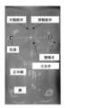
- FIG. 4 is a diagram showing an example of an anatomical map showing each placement position on the body surface of a specimen in two-dimensional space;
- FIG. 4 is a diagram showing an example of a procedure for estimating an arrangement position by the medical support robot apparatus according to one embodiment of the present invention. It is a figure which shows an example of a structure of the end effector of the medical assistance robot apparatus which concerns on one Embodiment of this invention.
- FIG. 5 is a diagram showing an example of a flow chart of processing for reconstructing a body surface shape in the medical assistance robot apparatus according to one embodiment of the present invention
- FIG. 5 is a diagram showing an example of a flow chart of processing for reconstructing a body surface shape in the medical assistance robot apparatus according to one embodiment of the present invention
- FIG. 5 is a diagram showing an example of a flowchart of processing for estimating an arrangement position in the medical support robot apparatus according to one embodiment of the present invention.
- FIG. 5 is a diagram showing an example of a flowchart of processing for estimating an arrangement position in the medical support robot apparatus according to one embodiment of the present invention
- FIG. 4 is a diagram showing an example of a flowchart of constant load passive scanning in the medical support robot apparatus according to one embodiment of the present invention
- FIG. 11 shows the positions of targets on a manikin in a multi-way registration experiment
- FIG. 10 is a diagram showing the positions of targets and four diagnostic sites on a mannequin in a multi-way registration experiment
- FIG. 10 is a diagram showing the results of multi-way registration with and without position feedback of the LiDAR camera
- FIG. 11 shows the results of registration error varying with the height of the LiDAR camera
- FIG. 10 is a diagram showing results of positioning errors for each estimated placement position
- FIG. 11 shows the static contact force results generated by the passive scanning mechanism in this example.
- FIG. 10 shows the results of the dynamic contact forces generated by the passive scanning mechanism in this example;
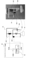
- FIG. 1 is a diagram showing an example of the configuration of a medical support robot apparatus according to this embodiment.
- a medical support robot apparatus 1 according to this embodiment includes a robot arm 10 , a constant load passive scanning mechanism (end effector) 20 , and an RGB-D camera 30 .
- the robot arm 10 is configured to be movable around a specimen 50, such as a patient's body, which is the object of medical treatment (FIG. 1 is a diagram for explanation, and the specimen 50 is replaced by a mannequin here). ing).
- a constant load passive scanning mechanism (end effector) 20 is provided integrally or detachably at the tip of the robot arm 10 .
- the constant load passive scanning mechanism 20 is a mechanism that holds the medical instrument 40 and allows the medical instrument 40 to be pressed against the body surface of the specimen 50 while maintaining a constant load.
- the medical instrument may correspond to general instruments such as an ultrasonic probe, a stethoscope, and the like necessary for medical treatment performed on the specimen 50 . More specifically, as a medical device that can be used in the medical support robot device 1 of the present embodiment, for example, Mitorica Co., Ltd.
- the robot arm 10 can be provided with an RGB-D camera 30 integrally or detachably at its tip.
- the RGB-D camera 30 is an example of an imaging sensor (ranging sensor) capable of simultaneously acquiring a color image (RGB information) and a distance image (distance information, depth information).
- the imaging sensor includes a light projector that outputs laser light such as ultraviolet light, visible light, and infrared light, and a light receiver that receives reflected light of the laser light reflected by the object to be measured.
- laser light such as ultraviolet light, visible light, and infrared light
- a light receiver that receives reflected light of the laser light reflected by the object to be measured.
- FoT Time of Flight
- pattern irradiation methods and the like as distance measurement methods in image sensors.
- the object is irradiated with a laser beam having a specific pattern.
- the imaging sensor of this embodiment is a LiDAR (Laser Imaging Detection and Ranging) camera.However, , is merely an example, and an imaging sensor using another method may be used.
- LiDAR Laser Imaging Detection and Ranging
- the medical support robot device 1 may include a client computer device 60.
- the client computer device 60 is directly or indirectly connected to each of the robot arm 10, the constant load passive scanning mechanism (end effector) 20, and the RGB-D camera 30 of the medical support robot device 1, and these configurations Send and receive data to and from each other.
- the client computer device 60 transmits a control signal for controlling each component or data necessary for operating each component.
- the client computer device 60 receives from each configuration the data obtained or generated at each configuration.
- the client computer device 60 can be realized by a hardware configuration similar to that of general computer devices.
- the client computer device 60 includes, for example, a CPU (Central Processing Unit) or a processor that can be realized by an electronic circuit such as a microprocessor, a RAM (Random Access Memory), a ROM (Read Only Memory), and a built-in hard disk device. , external hard disk drive, CD, DVD, USB memory, memory stick, removable memory such as SD card, input/output user interface (display, keyboard, mouse, touch panel, speaker, microphone, LED, etc.), medical support robot device 1 and a wired/wireless communication interface capable of communicating with other computer devices.
- a CPU Central Processing Unit
- a processor that can be realized by an electronic circuit such as a microprocessor, a RAM (Random Access Memory), a ROM (Read Only Memory), and a built-in hard disk device.
- external hard disk drive CD, DVD, USB memory, memory stick, removable memory such as SD card
- input/output user interface display, keyboard, mouse, touch panel, speaker, microphone, LED, etc.
- medical support robot device 1 and
- the processor reads a computer program previously stored in a hard disk device, ROM, removable memory, or the like into a memory area such as a RAM, and appropriately retrieves necessary data from the hard disk device, ROM, removable memory, or the like. Can be executed while reading.
- Such operations of the client computer device 60 implement various types of processing in the medical assistance robot device 1, which will be described in detail below.
- various data used in each process described in this embodiment is stored in a storage device or storage medium such as a hard disk device, RAM, removable memory, etc., and when the processor executes the computer program, Accordingly, it is read out to a memory area such as a RAM and used.
- part or all of the program executed by the client computer device 60 according to the present embodiment can be stored in a computer-readable medium and handed over, or can be downloaded via a wired or wireless communication network. is.
- the medical support robot device 1 illustrated in FIG. 1 is a medical support robot device actually constructed by the inventors of the present application. Universal Robot, Denmark), a LiDAR camera (Intel RealSense L515, Intel, USA) that acquires the three-dimensional contour of the surface of the specimen 50 as point cloud data as the RGB-D camera 30, and the robot arm 10
- This is a medical support robot device constructed using a client computer device 60 (Dell Precision 5380, Dell, USA) for acquiring point cloud data while synchronizing.
- the medical support robot apparatus 1 of this example is constructed on the assumption that auscultation is performed using a stethoscope as an example. Since FIG.
- the specimen 50 is a mannequin here, and as will be described later, the papilla and navel, which are landmarks of the specimen 50 in this example, are unclear on the mannequin. , the inventors have marked these positions.
- the configuration shown in FIG. 1 is merely an example, and needless to say, the configuration of the medical support robot apparatus 1 according to this embodiment is not limited to this. The same is true throughout the specification.
- a constant-load passive scanning mechanism using a spring is installed in the robot arm in order to adaptively grip the stethoscope (medical instrument) 40 against the body surface of the specimen 50.
- 10 end effectors 20 were implemented.
- a 6-axis force/torque sensor 25 (Axia-80-M20, ATI Industrial Automation, USA) is attached to the base of the constant load passive scanning mechanism (end effector) 20, and when the stethoscope 40 is placed on the body surface of the subject 50, Contact force was measured.
- the client computer device 60 that controls the medical support robot device 1 and an external server computer device (not shown) are directly connected to a network (1 GB/sec (gigabyte/second) speed), and the data transmission protocol is TCP/IP.
- the LiDAR camera 30 is provided inside the constant-load passive scanning mechanism (end effector) 20, but is not limited to this.
- the LiDAR camera 30 may be fixed so that its position relative to the robot arm 10 does not change, and may be installed at a location different from the constant load passive scanning mechanism (end effector) 20 .
- the LiDAR camera 30 acquires the shape depth and color information of the specimen 50 as point cloud data, and the point cloud data is coordinate registration (positioning) using the positional relationship between the robot arm 10 and the specimen 50.
- the LiDAR camera 30 is attached to the end effector 20 of the robot arm 10, even if the robot arm 10 moves around the specimen 50, the positional relationship between the LiDAR camera 30 and the robot arm 10 is kinematically remains fixed. Therefore, the acquired position of the point cloud data of the specimen 50 is linked with the coordinates of the robot arm 10 .
- FIG. 2 is a diagram for explaining coordinate transformation in the medical support robot apparatus 1 of this example, which is composed of the robot arm 10, the LiDAR camera 30, and the stethoscope (medical instrument) 40. As shown in FIG.
- the scan point in the LiDAR camera 30 coordinate space (P L ) is transformed to the robot arm 10 base 15 coordinate space (P B ), and the contact point with the specimen 50 in the stethoscope 40 coordinate space (P S ) is , can be transformed into the coordinate space (P L ) of the LiDAR camera 30 (equation (1)).
- CAD computer-aided design
- the robot arm 10 can be controlled by the programming language URScript (Universal Robots A/S) used in the medical support robot device 1.
- the client computer device 60 that controls the medical support robot device 1 can transmit URScript commands to an external server computer device (not shown) via socket communication.
- the point cloud data was acquired using the Intel RealSense SDK 2.0.
- a customized software system based on Python programming in Visual Studio Code can synchronize the control of the robotic arm 10 with the reading of the point cloud data.
- FIG. 3 is a diagram showing an example of a processing flow for the medical assistance robot apparatus 1 to bring the stethoscope (medical instrument) 40 into contact with the body surface of the specimen 50 and perform auscultation autonomously.
- the processing flow mainly includes the following components (A) to (C): (A) Reconstruction of body surface shape: Acquisition of point cloud data covering the entire chest of the specimen 50 (process (1)) and registration of the acquired point cloud data for reconstructing the shape of the entire chest ( alignment) (process (2)) (B) Estimation of placement position: Estimation of the placement position of the stethoscope 40 (processing ( 4)) (C) Constant force passive scanning: Place the stethoscope 40 at the position estimated in (B) above while maintaining a constant contact force.
- (A) Body surface shape reconstruction (point cloud data registration)
- ICP iterative closest point
- pairwise global registration which is more than an order of magnitude faster and more robust to noise than general registration pipeline processing, is widely used.
- This approach can also be employed in the registration of multiple surfaces to acquire models of large scenes or objects. Note that this procedure is known as multi-way registration.
- the system coordinates of the captured data set (local coordinates in the medical support robot device 1; the same shall apply hereinafter) are converted to global coordinates. It is believed that the registration error is minimized because it is possible to As an advantage of the medical support robot device developed by the inventors, the position of the LiDAR camera 30 when each data set of the point cloud is captured can be accurately determined based on the encoders mounted on each joint of the robot arm 10. The point is that it can be obtained.
- J r and r are the Jacobian matrix and residual vector, respectively.
- the registration pipeline processing is as follows: First, the LiDAR camera 30 attached to the end effector 20 of the robot arm 10 moves several points away from the specimen 50 and captures (photographs) the body surface of the specimen 50 . Next, each of the coordinates of the captured data set is transformed into robot arm 10 based global coordinates. Multi-way registration is performed using the point cloud data set expressed in global coordinates. Each of the datasets is combined as one dataset using the estimated transformations in each of the datasets. Finally, a filter that removes inlier and outlier point clouds is applied to the combined data.
- (B) Estimation of Placement Position Auscultation is mainly performed to examine the circulatory system and respiratory system, ie heart sounds and breath sounds.
- examination of the circulatory system will be described as an example.
- a stethoscope is brought into contact with four points of the specimen 50 to listen to sounds of the tricuspid valve, mitral valve, pulmonary valve, and aortic valve.
- the tricuspid, mitral, pulmonary, and aortic valve sounds are each roughly located on the left side of the substernal near the 5th intercostal space and the 5th on the left side of the midclavicular line.
- the medical support robot apparatus 1 must recognize each position in order to autonomously auscultate sounds from these four positions.
- the positions of the nipple and navel of the specimen 50 are used when estimating each position on the body surface.
- the nipple and navel are usable landmarks that the medical assistance robot apparatus 1 can easily recognize on the body surface.
- the papillae are located roughly in the 4th intercostal space (Fig. 4).
- the location can be a landmark for finding each placement location based on the anatomical relationship between each rib and its intercostal space. See, for example, J. A. Cook, S. S. Tholpady, A. Momeni, and M. W. Chu, “Predictors of internal mammary vessel diameter: A computed tomographic angiography-assisted anatomic analysis,” J. Plast. Reconstr.
- Intercostal space and rib height are measured using CT scan data. Based on this anatomical statistical data, the length along the craniocaudal direction between the 4th intercostal space (position of the papilla) and the 2nd intercostal space (position of the aortic and pulmonary valves) is 39 mm (millimeters). The length along the craniocaudal direction between the 4th intercostal space (papilla position) and the 5th intercostal space (mitral and tricuspid valve positions) averaged 20.6 mm.
- each length of each valve on the y-axis (cephalo-caudal axis) of the system coordinates of the medical assistance robot device 1 local coordinates in the medical assistance robot device 1).
- the position of the midline of the abdomen is required.
- the midline can be identified by drawing a straight line between the midpoint of the line segment connecting the left and right papillae and the navel (Fig. 5).
- the midclavicular line, where the mitral valve is located is about 100 mm away from the midline along the x-axis (e.g., R. A. Sayeed and G. E. Darling, “Surface Anatomy and Surface Landmarks for Thoracic Surgery,” Thorac Surg. Clin., vol. 17, no. 4, pp. 449-461, 2007.).
- the other valves are located near the medial edge of the intercostal space, so the stethoscope should be placed around the rim of the sternum.
- the average width of the sternum in men is 25.99 mm (see, for example, J. S. Bruce, “Utility of the sternum to estimate sex and age,” Bost. Univ.
- the measured value of the distance between the left and right papillae which is a landmark on the body surface of the specimen 50, is compared with the statistical average value, and the measured value is compared with the difference from the average value.
- the length or the like used to specify each organ or each inspection position may be enlarged or reduced and used for estimation of an inspection position, which will be described later.
- each placement position of the stethoscope 40 for listening to the four valve sounds can be deduced.
- the overall procedure for estimating the placement position is as follows (Fig. 5): (i) Using the template matching method, locate the nipple and navel from each of the multiple color images captured by the LiDAR camera 30; Extract as two-dimensional pixel positions.
- each position of the diagnostic site on the two-dimensional pixel space of the color image can be estimated based on the anatomical map (FIG. 4) described above.
- the extracted two-dimensional pixel positions in the color image are projected into the three-dimensional coordinate space of the reconstructed body surface by transformation based on the intrinsic camera parameters.
- each examination position may be more general than when listening to heart sounds.
- FIG. 6 is a diagram showing an example of the configuration of the developed end effector 20. As shown in FIG. The role of this passive scanning mechanism is to place the stethoscope 40 on the body surface of the specimen 50 in a safe and constant manner regardless of the pushing displacement by the robot arm 10 when placing the stethoscope 40 at the estimated placement position of the specimen 50 . It is to contact with contact force.
- the safe constant contact force may be a predetermined constant value with reference to a general pressing force when a doctor applies a stethoscope to a patient's body.
- a certain amount of error may occur between the actual position of the stethoscope 40 and the placement position on the body surface, for example, when the body surface of the specimen 50 shifts due to patient's respiratory motion or the like.
- the end effector 20 according to this embodiment can correct the error while maintaining the contact force within a certain range.
- the end effector 20 shown in FIG. 6 includes a linear servo actuator 202 (L1220PT, MigthyZap, Korea), a linear spring 204, an optical distance sensor 206 (ZX-LD100L, Omron, Japan), a linear guide 208 (SSE2B6-70, Misumi, Japan).
- the linear servo actuator 202 vertically moves up and down with respect to the body surface of the specimen 50 while maintaining the amount of compression of the linear spring 204 at a predetermined constant amount.
- the linear spring modulus was 0.45 N/mm (Newtons/mm) and two springs were inserted.
- the optical distance sensor 206 measured the amount of compression of the linear spring 204 in real time.
- the linear servo actuator 202 was controlled via an iOS-based PID controller 62 (IR-STS01, MigthyZap, Korea).
- the values measured by the optical distance sensor 206 were transferred to the client computer device 60 via a DAQ (Data Acquisition) tool (Analog Discovery 2, Digilent, USA).
- a software system of the client computer device 60 custom designed based on Python programming in Visual Studio Code, synchronizes the control of the linear servo actuator 202 with the reading of measurement data from the optical distance sensor 206 .
- a PID (Proportional Integral Differential) control scheme was used to control the position of the linear servo actuator 202 based on the feedback from the optical distance sensor 206 . More specifically, as shown in FIG.
- the distance from the optical distance sensor 206 to the body surface of the specimen 50 is measured by the optical distance sensor 206 and the measured value is output to the PID controller 62 .
- the displacement of the body surface of the subject 50 caused by the patient's respiratory motion or the like is corrected.
- the amount of compression of the linear spring 204 taken into account is determined and output to the linear servo actuator 202 as a command value.
- Linear servo actuator 202 changes the compression state of linear spring 204 based on the command value.
- FIG. 7 (flowchart) An example of processing executed by the medical assistance robot apparatus 1 according to the present embodiment will be described below with reference to the flow charts of FIGS. 7 to 11.
- FIG. 7 (flowchart) An example of processing executed by the medical assistance robot apparatus 1 according to the present embodiment will be described below with reference to the flow charts of FIGS. 7 to 11.
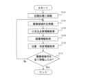
- FIG. 7 is a diagram showing an example of a flowchart of the process ((1) in FIG. 3) in which the LiDAR camera 30 takes an image of the specimen 50.
- the LiDAR camera 30 moves to a predetermined initial position (step S102).
- the LiDAR camera 30 acquires three-dimensional point cloud information (acquired three-dimensional point cloud information) at each imaging location while moving within the imaging region (the entire chest of the specimen 50 in this embodiment) (step S104) (step S106).
- the LiDAR camera 30 acquires two-dimensional color image information at each imaging location and position/angle information (camera position coordinate information) of the LiDAR camera 30 at each imaging position (steps S108 and S110).
- the above processing is continued until the entire imaging area is moved (step S112).
- the above processing can be executed by controlling the robot arm 10 and the LiDAR camera 30 by a control signal from the client computer device 60 . (The same applies to each process described below.)
- FIG. 8 shows a process of reconstructing the body surface shape of the specimen 50 using a plurality of acquired three-dimensional point cloud information and a plurality of camera position coordinate information acquired by the process of FIG. 7 ((2) in FIG. 3). It is a figure which shows an example of the flowchart of.
- Acquired 3D point cloud information acquired from N locations (N is an integer of 2 or more) is converted from local coordinates to global coordinates based on the position and angle information (position coordinate information) of the LiDAR camera 30 at each imaging position.
- step S202 A correspondence relationship between overlapping points in each acquired three-dimensional point group information is searched (step S204).
- the N pieces of acquired 3D point group information are integrated into one piece of 3D point group information (integrated 3D point group information) based on the correspondence relationship between overlapping points searched in step S204 (step S206).
- FIG. 9 is a diagram showing an example of a flowchart of the process of extracting landmarks on the body surface of the specimen 50 ((3) in FIG. 3).
- the nipple and navel of the specimen 50 are extracted from each of the image information acquired from the N points by a template matching method or the like (step S302).
- the extracted pixel position information of the nipple and navel is converted into coordinates on point cloud coordinates (step S304).
- the position of the midline of the abdomen is identified from the positional information (coordinates) of the nipple and navel on the point cloud coordinates and the point cloud distribution of the entire specimen (step S306).
- FIG. 10 is a diagram showing an example of a flowchart of the process of estimating the placement position where the stethoscope 40 should be placed ((4) in FIG. 3).
- a diagnosis site is specified (step S402).
- auscultation sites namely, the tricuspid valve, mitral valve, pulmonary valve, and aortic valve. These designations may be input by a user (operator, etc.) of the medical support robot apparatus 1 through an input/output user interface such as a keyboard of the client computer apparatus 60, for example.
- This input content may be stored in a hard disk device, RAM, or the like, and read out from the hard disk device, RAM, or the like when step S402 is executed.
- the placement position near the diagnosis site is determined (step S404).
- the diagnosis site is converted into the arrangement position on the point cloud coordinates (step S406).
- the medical support robot apparatus 1 moves based on the arrangement position on the point cloud coordinates of the diagnostic part converted in step S406 (step S408). This is followed by step S508 of FIG.
- FIG. 11 is a diagram showing an example of a flowchart of constant load passive scanning ((C) in FIG. 3).
- each configuration is calibrated (step S502).
- a load target load
- the setting may be input by a user (operator, etc.) of the medical assistance robot apparatus 1 through an input/output user interface such as a keyboard of the client computer apparatus 60, for example. Then, this input content may be saved in a hard disk device, RAM, or the like.
- the client computer device 60 of the medical assistance robot apparatus 1 calculates the required spring compression amount required for the target load set in step S504 (step S506).
- the medical assistance robot apparatus 1 executes the processes of steps S502 to S506 as preparations.
- the robot arm 10 of the medical assistance robot apparatus 1 is operated to hold the stethoscope 40 based on the arrangement position of the diagnostic region on the point cloud coordinates converted in step S406 in FIG. Then, the linear servo actuator 202 of the constant-load passive scanning mechanism 20 moves to the arrangement position on the point group coordinates of the diagnostic site, and the stethoscope 40 is brought into contact with the body surface of the specimen 50 and pressed with a predetermined contact force (step S508).
- Optical distance sensor 206 measures the length of linear spring 204 (step S510).
- step S512 When the length of the linear spring 204 measured in step S510 reaches the limit value (step S512: Yes), the medical support robot apparatus 1 moves to the initial position because the process cannot be continued any more. to end the process (step S518).
- processing such as changing the initial value of the contact force of the stethoscope 40 in step S508 may be performed, and the auscultation processing may be re-executed.
- step S512 determines whether the length of the linear spring 204 has reached the required spring compression amount calculated in step S506 (step S514). If it has not reached (step S514: No), the contact force is insufficient, so the process returns to step S508, and the linear servo actuator 202 operates so that the compression amount of the linear spring 204 increases. Further, when the client computer device 60 of the medical assistance robot apparatus 1 determines in step S514 that the length of the linear spring 204 has reached the required spring compression amount (step S514: Yes), the stethoscope 40 Perform auscultation of the diagnostic site.
- the medical instrument 40 is an ultrasonic probe
- a diagnostic image detected by the ultrasonic probe while moving in a specific range on the body surface of the specimen 50 while being pressed against the ultrasonic probe is sent to the client at any time. It is output to computer device 60 .
- the doctor can then view the diagnostic image on the client computer device 60 or a remote computer device and make a diagnosis.
- the client computer device 60 determines the compression amount of the linear spring 204 in consideration of the displacement of the body surface of the specimen 50 caused by the respiratory motion of the patient, etc., and the stethoscope 40 accurately reaches the target position. It is determined whether or not (step S516). If the stethoscope 40 does not exactly reach the target position, the process may return to step S508 to adjust the position of the constant force passive scanning mechanism 20 holding the stethoscope 40 .
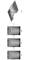
- FIG. 12A is a diagram showing target positions on a manikin in a multi-way registration experiment.
- FIG. 12B is a diagram showing the positions of targets and four diagnostic sites on a mannequin in this experiment.
- point cloud data at five positions: ⁇ 200 mm, ⁇ 100 mm, 0 mm, 100 mm, 200 mm with the origin at the midline of the specimen 50 along the x-axis as shown in FIG. 12A. was obtained (taken by the LiDAR camera 30).
- each point cloud data is coordinate-transformed into the system coordinates of the medical assistance robot device 1 (local coordinates in the medical assistance robot device 1) based on the position information (equation (1)) of the LiDAR camera 30. Indicates processing.
- the accuracy of the point cloud depends on the distance between the LiDAR camera 30 and the subject, the distance from the LiDAR camera 30 to the specimen 50 is changed in three steps (250 mm, 300 mm, and 350 mm from the upper end of the chest of the specimen 50) to obtain the point cloud. got the data.
- the robot arm 10 was moved to four targets on the specimen 50 based on the reconstructed body surface data, namely the left and right papillae, epigastrium, and umbilicus (Fig. 12A), the distance between the tip of the end effector 20 and each target was measured in three-dimensional coordinate space. The position of each target was manually indicated on the reconstructed body surface data in this experiment.
- a jig was attached to the robot arm 10 and the center of the end effector 20 was identified (Fig. 12A). Twelve tests were performed for each condition.
- the safety of the end effector 20 having the passive scanning mechanism described in "(C) Constant Force Passive Scanning” above is evaluated by measuring both static and dynamic contact forces.
- the “static contact force” means the contact force measured while the medical instrument (stethoscope) 40 is in contact with the body surface and kept stationary.
- “dynamic contact force” means a contact force generated during an operation from the air to contact of the medical instrument (stethoscope) 40 with the body surface. In this experiment, static contact force was measured after pushing the stethoscope 40 5 mm against the ground. Also, three types of contact forces (5N, 10N, 15N) were set. Also, 12 trials were performed for each condition.
- a dynamic contact force was measured as the stethoscope 40 was moved from the air to the body surface of the manikin.
- the initial position of the stethoscope 40 was 5 mm from the body surface of the subject 50 along the z-axis (the vertical direction of the subject 50 (manikin) lying supine). From here, the stethoscope 40 was moved 10 mm along the z-axis and pressed against the body surface of the specimen 50 by 5 mm.
- the target contact force in this experiment was set at 5N.
- FIG. 13 shows the results of multi-way registration with and without position feedback of the LiDAR camera 30 .
- the upper part shows the estimation result for each height without position feedback
- the lower part shows the estimation result for each height with position feedback.
- the reconstruction with positional feedback at any height shows the chest shape of the specimen 50 more accurately than the reconstruction without positional feedback from the LiDAR camera 30.
- FIG. 14 is a diagram showing the results of the registration error that changes according to the height of the LiDAR camera 30. As shown in FIG. According to the results shown in FIG. 14, it can be seen that the error decreases as the distance between the LiDAR camera 30 and the target decreases.
- FIG. 15 is a diagram showing the result of the positioning error for each estimated arrangement position. Errors for the tricuspid valve were small compared to those for the other valves. A two-tailed t-test with 90% confidence intervals was also used for positioning accuracy dependent on target valve position. There was a significant difference in the error of the three-dimensional spatial coordinates between the tricuspid valve and the other valves (p ⁇ 0.01).
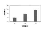
- FIG. 16A shows the results of the static contact force generated by the passive scanning mechanism in this example.
- FIG. 16B shows the results of the dynamic contact forces generated by the passive scanning mechanism in this example.
- the static contact force results showed that the contact force generated (vertical axis) was exactly achieved for the target force (horizontal axis) under all conditions.
- the time-series measurements increased (0.5 seconds) slightly above the target value when the specimen 50 touched the body surface. However, measurements were immediately adjusted to match target values.
- the maximum contact force measured was 5.36 N, which was 7.2% of the target value.
- the position to be brought into contact with the medical instrument can be determined without human intervention. It is possible for the medical support robot device to automatically judge. Also, thereafter, the medical device can be moved on the body surface while maintaining a predetermined contact force. With such a function, it becomes possible to operate the medical support robot apparatus fully automatically, which conventionally could only be operated semi-automatically.
- the papillae and the navel are used as landmarks on the body surface of the specimen 50, but any visible parts of the human body may be used.
- joint parts such as the shoulder, collarbone, or pelvis can be easily identified from the appearance, and each joint part can be used as a landmark.
- publicly known software for example, open source software “OpenPose”
- OpenPose open source software
- the position of the midline of the abdomen is determined from the positions of the papilla and navel, which are landmarks, and the point cloud coordinates are determined using the anatomical positional relationship between the midline of the abdomen and each diagnostic site.
- the position of each diagnostic site is estimated above, it is of course possible to directly estimate the position of the diagnostic site from the position of the landmark depending on the positional relationship between the landmark and the diagnostic site.
- the medical device may be another medical device such as an ultrasound probe used in ultrasound examinations.
- the present invention can be applied to a case in which a medical instrument such as an ultrasonic probe is pressed against a specific range on the body surface of the subject 50 with a predetermined contact force.
Landscapes
- Health & Medical Sciences (AREA)
- Life Sciences & Earth Sciences (AREA)
- Engineering & Computer Science (AREA)
- Surgery (AREA)
- General Health & Medical Sciences (AREA)
- Medical Informatics (AREA)
- Physics & Mathematics (AREA)
- Nuclear Medicine, Radiotherapy & Molecular Imaging (AREA)
- Biomedical Technology (AREA)
- Veterinary Medicine (AREA)
- Public Health (AREA)
- Animal Behavior & Ethology (AREA)
- Molecular Biology (AREA)
- Heart & Thoracic Surgery (AREA)
- Radiology & Medical Imaging (AREA)
- Pathology (AREA)
- Biophysics (AREA)
- Theoretical Computer Science (AREA)
- General Physics & Mathematics (AREA)
- Robotics (AREA)
- Acoustics & Sound (AREA)
- Computer Vision & Pattern Recognition (AREA)
- Quality & Reliability (AREA)
- Manipulator (AREA)
Priority Applications (2)
| Application Number | Priority Date | Filing Date | Title |
|---|---|---|---|
| US18/719,225 US20250064534A1 (en) | 2021-12-17 | 2022-12-02 | Medical support method, medical support robot device, and computer program |
| JP2023567696A JPWO2023112728A1 (https=) | 2021-12-17 | 2022-12-02 |
Applications Claiming Priority (2)
| Application Number | Priority Date | Filing Date | Title |
|---|---|---|---|
| JP2021205070 | 2021-12-17 | ||
| JP2021-205070 | 2021-12-17 |
Publications (1)
| Publication Number | Publication Date |
|---|---|
| WO2023112728A1 true WO2023112728A1 (ja) | 2023-06-22 |
Family
ID=86774299
Family Applications (1)
| Application Number | Title | Priority Date | Filing Date |
|---|---|---|---|
| PCT/JP2022/044587 Ceased WO2023112728A1 (ja) | 2021-12-17 | 2022-12-02 | 医療支援方法、医療支援ロボット装置、およびコンピュータプログラム |
Country Status (3)
| Country | Link |
|---|---|
| US (1) | US20250064534A1 (https=) |
| JP (1) | JPWO2023112728A1 (https=) |
| WO (1) | WO2023112728A1 (https=) |
Cited By (2)
| Publication number | Priority date | Publication date | Assignee | Title |
|---|---|---|---|---|
| CN117017339A (zh) * | 2023-08-02 | 2023-11-10 | 齐鲁工业大学(山东省科学院) | 一种机械臂自动听诊方法 |
| WO2025100049A1 (ja) * | 2023-11-06 | 2025-05-15 | 国立研究開発法人産業技術総合研究所 | 超音波検査装置 |
Families Citing this family (1)
| Publication number | Priority date | Publication date | Assignee | Title |
|---|---|---|---|---|
| US20260060648A1 (en) * | 2024-08-27 | 2026-03-05 | Siemens Medical Solutions Usa, Inc. | Markerless Pose Estimation of a Medical Device from a Single Camera |
Citations (3)
| Publication number | Priority date | Publication date | Assignee | Title |
|---|---|---|---|---|
| US20170220709A1 (en) * | 2016-02-03 | 2017-08-03 | Varian Medical Systems, Inc. | System and method for collision avoidance in medical systems |
| JP2020168359A (ja) * | 2019-04-03 | 2020-10-15 | キヤノンメディカルシステムズ株式会社 | 医用画像診断装置、手術支援ロボット装置、手術支援ロボット用制御装置及び制御プログラム |
| JP2021166593A (ja) * | 2020-04-09 | 2021-10-21 | 株式会社メディカロイド | ロボット手術支援システム、ロボット手術支援方法、及びプログラム |
-
2022
- 2022-12-02 US US18/719,225 patent/US20250064534A1/en active Pending
- 2022-12-02 JP JP2023567696A patent/JPWO2023112728A1/ja active Pending
- 2022-12-02 WO PCT/JP2022/044587 patent/WO2023112728A1/ja not_active Ceased
Patent Citations (3)
| Publication number | Priority date | Publication date | Assignee | Title |
|---|---|---|---|---|
| US20170220709A1 (en) * | 2016-02-03 | 2017-08-03 | Varian Medical Systems, Inc. | System and method for collision avoidance in medical systems |
| JP2020168359A (ja) * | 2019-04-03 | 2020-10-15 | キヤノンメディカルシステムズ株式会社 | 医用画像診断装置、手術支援ロボット装置、手術支援ロボット用制御装置及び制御プログラム |
| JP2021166593A (ja) * | 2020-04-09 | 2021-10-21 | 株式会社メディカロイド | ロボット手術支援システム、ロボット手術支援方法、及びプログラム |
Cited By (3)
| Publication number | Priority date | Publication date | Assignee | Title |
|---|---|---|---|---|
| CN117017339A (zh) * | 2023-08-02 | 2023-11-10 | 齐鲁工业大学(山东省科学院) | 一种机械臂自动听诊方法 |
| CN117017339B (zh) * | 2023-08-02 | 2024-04-30 | 齐鲁工业大学(山东省科学院) | 一种机械臂自动听诊方法 |
| WO2025100049A1 (ja) * | 2023-11-06 | 2025-05-15 | 国立研究開発法人産業技術総合研究所 | 超音波検査装置 |
Also Published As
| Publication number | Publication date |
|---|---|
| US20250064534A1 (en) | 2025-02-27 |
| JPWO2023112728A1 (https=) | 2023-06-22 |
Similar Documents
| Publication | Publication Date | Title |
|---|---|---|
| Huang et al. | Robotic arm based automatic ultrasound scanning for three-dimensional imaging | |
| US12472117B2 (en) | Systems and methods for assisting surgery | |
| WO2023112728A1 (ja) | 医療支援方法、医療支援ロボット装置、およびコンピュータプログラム | |
| Hennersperger et al. | Towards MRI-based autonomous robotic US acquisitions: a first feasibility study | |
| Virga et al. | Automatic force-compliant robotic ultrasound screening of abdominal aortic aneurysms | |
| Huang et al. | Robot-assisted autonomous ultrasound imaging for carotid artery | |
| CN113940755A (zh) | 一种术像一体的外科手术规划与导航方法 | |
| JP6715823B2 (ja) | X線スイートにおける画像統合及びロボット内視鏡制御 | |
| CN113316430B (zh) | 机器人装置的运动编程 | |
| JP6475324B2 (ja) | オプティカルトラッキングシステム及びオプティカルトラッキングシステムの座標系整合方法 | |
| Ma et al. | A-see: Active-sensing end-effector enabled probe self-normal-positioning for robotic ultrasound imaging applications | |
| US20130123801A1 (en) | Method of real-time tracking of moving/flexible surfaces | |
| CN112270993B (zh) | 一种以诊断结果为反馈的超声机器人在线决策方法及系统 | |
| CN112151169B (zh) | 一种仿人操作的超声机器人自主扫描方法及系统 | |
| Tsumura et al. | Towards fully automated robotic platform for remote auscultation | |
| CN112132805B (zh) | 一种基于人体特征的超声机器人状态归一化方法及系统 | |
| Roshan et al. | Robotic ultrasonography for autonomous non-invasive diagnosis—A systematic literature review | |
| Ferguson et al. | Toward image-guided partial nephrectomy with the da Vinci robot: exploring surface acquisition methods for intraoperative re-registration | |
| CN117338418A (zh) | 一种基于肝肿瘤消融的超声定位系统及其方法 | |
| Piccinelli et al. | Rigid 3D registration of pre-operative information for semi-autonomous surgery | |
| Ferguson et al. | Toward practical and accurate touch-based image guidance for robotic partial nephrectomy | |
| US20210298848A1 (en) | Robotically-assisted surgical device, surgical robot, robotically-assisted surgical method, and system | |
| Wang et al. | Robotic assistance for standardized compression ultrasound elastography | |
| WO2024080291A1 (ja) | 医用ナビゲーション方法、医用ナビゲーションシステム、およびコンピュータプログラム | |
| Zheng et al. | Fiducial Marker Based Patient-to-Robot Registration and Target Tracking for Automatic Extra-body Ultrasound Imaging |
Legal Events
| Date | Code | Title | Description |
|---|---|---|---|
| 121 | Ep: the epo has been informed by wipo that ep was designated in this application |
Ref document number: 22907256 Country of ref document: EP Kind code of ref document: A1 |
|
| WWE | Wipo information: entry into national phase |
Ref document number: 2023567696 Country of ref document: JP |
|
| WWE | Wipo information: entry into national phase |
Ref document number: 18719225 Country of ref document: US |
|
| NENP | Non-entry into the national phase |
Ref country code: DE |
|
| 122 | Ep: pct application non-entry in european phase |
Ref document number: 22907256 Country of ref document: EP Kind code of ref document: A1 |
|
| WWP | Wipo information: published in national office |
Ref document number: 18719225 Country of ref document: US |