WO2023106372A1 - Enzyme measurement method, microchamber array, kit, method for capturing raman scattering image, and method for measuring target molecule - Google Patents
Enzyme measurement method, microchamber array, kit, method for capturing raman scattering image, and method for measuring target molecule Download PDFInfo
- Publication number
- WO2023106372A1 WO2023106372A1 PCT/JP2022/045297 JP2022045297W WO2023106372A1 WO 2023106372 A1 WO2023106372 A1 WO 2023106372A1 JP 2022045297 W JP2022045297 W JP 2022045297W WO 2023106372 A1 WO2023106372 A1 WO 2023106372A1
- Authority
- WO
- WIPO (PCT)
- Prior art keywords
- enzyme
- selective substrate
- reaction product
- enzymatic reaction
- microchambers
- Prior art date
Links
Images


Classifications
-
- G—PHYSICS
- G01—MEASURING; TESTING
- G01N—INVESTIGATING OR ANALYSING MATERIALS BY DETERMINING THEIR CHEMICAL OR PHYSICAL PROPERTIES
- G01N21/00—Investigating or analysing materials by the use of optical means, i.e. using sub-millimetre waves, infrared, visible or ultraviolet light
- G01N21/62—Systems in which the material investigated is excited whereby it emits light or causes a change in wavelength of the incident light
- G01N21/63—Systems in which the material investigated is excited whereby it emits light or causes a change in wavelength of the incident light optically excited
- G01N21/65—Raman scattering
Definitions
- the present invention relates to an enzyme measurement method, a microchamber array, a kit, a Raman scattering image imaging method, and a target molecule measurement method.
- Enzymes change the structure of substrate molecules through reactions such as hydrolysis and transfer. Thousands of types of enzymes exist in living organisms and are responsible for functions such as metabolism, absorption, and signal transduction. Body fluids such as blood, saliva, and urine contain trace amounts of enzymes produced in organs, etc., and when a specific organ malfunctions, the activity levels of related enzymes in the body fluids decrease. Conversely, when intracellular enzymes leak into body fluids such as blood due to organ inflammation or degeneration of nerve cells, the activity of related enzymes is enhanced. Since changes in enzyme activity (enzyme concentration) in body fluids correlate with the progression of various diseases, they are often used as minimally invasive and early disease diagnostic indicators.
- Patent Document 1 describes detection of enzymatic activity at the single-molecule level using a femtoliter-order microchamber.
- a challenge in expanding disease diagnosis based on enzyme activity is the improvement of enzyme activity measurement technology.
- the measurement of enzyme activity in a sample has used a labeled substrate that exhibits a fluorescence or color reaction accompanying an enzyme reaction.
- this is an important method for measuring enzymatic activity with high sensitivity
- enzyme species that are difficult to measure because bulky labels interfere with enzymatic reactions.
- multiple types of enzymes react with labeled substrates, making it difficult to discuss only enzymes that contribute to disease from among mixed enzyme groups.
- Raman scattering spectroscopy especially surface-enhanced Raman scattering (SERS) spectroscopy, which is expected to be highly sensitive, is a promising method for quantifying enzyme activity without labeling.
- SERS is a highly sensitive vibrational spectroscopy that utilizes an optically enhanced field formed in metal nanostructures.
- a metal nanostructure with a size smaller than the wavelength is irradiated with light, localized surface plasmons, which are collective excitations of electrons, are induced.
- the plasmons will interact with each other, and an extremely strong enhanced electric field will be formed between the metal nanostructures.
- SERS spectroscopy in addition to this electric field enhancement effect, chemical effects derived from metal-molecule interactions are also observed.
- SERS spectroscopy is promising for increasing the sensitivity of Raman scattering spectroscopy because the signal light intensity is greatly enhanced by the electric field enhancement effect and the chemical effect.
- the linewidth of the scattering spectrum found in SERS spectroscopy is narrow compared to the fluorescence emission spectrum. Therefore, it is expected that the reaction products of multiple enzymes can be discriminated and the activities of multiple enzymes can be measured at the same time without spectral overlap.
- the present invention has been made in view of the above circumstances, and provides a technique that can measure enzymes in samples without labeling and with excellent sensitivity.
- the present invention includes the following aspects.
- a mixed solution preparation step of preparing a mixed solution containing an enzyme and a selective substrate of the enzyme an array preparation step of preparing a metal nanostructure-immobilized microchamber array having a plurality of microchambers in which metal nanostructures are immobilized; a mixed liquid enclosing step of enclosing the mixed liquid so that the number of molecules of the enzyme is one or less in each of the plurality of microchambers;
- the metal nanostructure-immobilized microchamber array is illuminated with excitation light, the enzymatic reaction product of the selective substrate or the surface-enhanced Raman scattering intensity derived from the selective substrate changes to a preset value or more.
- the enzymatic reaction product exhibits a structure different from that of the selective substrate, and the Raman peak is capable of distinguishing between the enzymatic reaction product and the selective substrate. Enzyme measurement method.
- a mixed solution preparation step of preparing a mixed solution containing an enzyme and a selective substrate of the enzyme an array preparation step of preparing a metal nanostructure-immobilized microchamber array having a plurality of microchambers in which metal nanostructures are immobilized; a mixed liquid enclosing step of enclosing the mixed liquid so that the number of molecules of the enzyme is one or less in each of the plurality of microchambers;
- a chronological measurement step of measuring to The enzymatic reaction product exhibits a structure different from that of the selective substrate, and the Raman peak is capable of distinguishing between the enzymatic reaction product and the selective substrate.
- Enzyme measurement method [3] a mixed solution preparation step of preparing a mixed solution containing multiple types of enzymes and multiple types of selective substrates corresponding to the multiple types of enzymes; an array preparation step of preparing a metal nanostructure-immobilized microchamber array having a plurality of microchambers in which metal nanostructures are immobilized; a mixed solution enclosing step of enclosing the mixed solution in each of the plurality of microchambers so that the number of molecules of at least one of the plurality of types of enzymes is 1 or less; When the metal nanostructure-immobilized microchamber array is illuminated with excitation light, the enzymatic reaction product of the selective substrate or the surface-enhanced Raman scattering intensity derived from the selective substrate changes to a preset value or more,
- a chronological measurement step of measuring to The enzymatic reaction product exhibits a structure different from that of the selective substrate, the Raman peak distinguishes between the enzymatic reaction product and the selective substrate, and the plurality of types of enzymatic reaction products have different structures. and can distinguish between multiple types of the enzymatic reaction products or the selective substrates at the Raman peak, Enzyme measurement method.
- Enzyme measurement method [6] a mixture preparation step of preparing a mixture containing an enzyme, a selective substrate of the enzyme, and a metal nanostructure; a droplet splitting step of splitting the mixed solution into a plurality of droplets containing one or less molecules of the enzyme; A temporal measurement step of illuminating the plurality of droplets with excitation light to measure the enzymatic reaction product of the selective substrate or the surface-enhanced Raman scattering intensity derived from the selective substrate for each of the plurality of droplets over time. and including The enzymatic reaction product exhibits a structure different from that of the selective substrate, and the Raman peak is capable of distinguishing between the enzymatic reaction product and the selective substrate. Enzyme measurement method.
- a mixed solution preparation step of preparing a mixed solution containing multiple types of enzymes, multiple types of selective substrates corresponding to the multiple types of enzymes, and metal nanostructures; a droplet splitting step of splitting the mixed solution into a plurality of droplets containing one or less molecules of at least one of the plurality of types of enzymes; By illuminating the plurality of droplets with excitation light, the surface-enhanced Raman scattering intensity derived from the enzyme reaction product of the selective substrate or the selective substrate has changed to a preset value or more, or has a preset threshold value or more.
- the enzymatic reaction product exhibits a structure different from that of the selective substrate, the Raman peak distinguishes between the enzymatic reaction product and the selective substrate, and the plurality of types of enzymatic reaction products have different structures. and can distinguish between multiple types of the enzymatic reaction products or the selective substrates at the Raman peak, Enzyme measurement method.
- a mixed solution preparation step of preparing a mixed solution containing multiple types of enzymes, multiple types of selective substrates corresponding to the multiple types of enzymes, and metal nanostructures; a droplet splitting step of splitting the mixed solution into a plurality of droplets containing one or less molecules of at least one of the plurality of types of enzymes; A temporal measurement step of illuminating the plurality of droplets with excitation light to measure the enzymatic reaction product of the selective substrate or the surface-enhanced Raman scattering intensity derived from the selective substrate for each of the plurality of droplets over time.
- the enzymatic reaction product exhibits a structure different from that of the selective substrate, the Raman peak distinguishes between the enzymatic reaction product and the selective substrate, and the plurality of types of enzymatic reaction products have different structures. and can distinguish between multiple types of the enzymatic reaction products or the selective substrates at the Raman peak, Enzyme measurement method.
- the metal nanostructure-immobilized microchamber array in which the mixture is enclosed in each microchamber is illuminated with wide-field illumination, and the position of the Raman peak is Acquire a Raman scattering image in the wavelength band of the Raman peak of the enzyme reaction product or the selective substrate using a narrow linewidth bandpass filter that matches the surface-enhanced Raman scattering light intensity and intensity of each microchamber.
- a method for measuring the enzyme according to claim 1 Acquiring Raman scattering images in the top wavelength band of the Raman peak and the bottom wavelength band of the Raman peak of the enzyme reaction product or the selective substrate, and taking the difference between the two to obtain the The method for measuring an enzyme according to [11], which quantifies surface-enhanced Raman scattering light intensity. [13] The method for measuring an enzyme according to any one of [1] to [12], wherein the enzymatic reaction product has a thiol group.
- the selective substrate for acetylcholinesterase is MATP+ and the selective substrate for butyrylcholinesterase is butyrylthiocholine.
- a microchamber array having a plurality of microchambers in which metal nanostructures are immobilized.
- [21] The method for photographing a Raman scattering image according to [20], further comprising matching the transmission wavelength band of the narrow bandpass filter to the bottom of the Raman peak of the target molecule.
- [22] The method of taking a Raman scattering image according to [20] or [21], wherein the target molecule is arranged in the plurality of microchambers of a microchamber array having a plurality of microchambers.
- [23] The method for photographing a Raman scattering image according to [22], wherein metal nanostructures are solid-phased in the plurality of microchambers.
- the transmission wavelength band of the narrow bandpass filter is aligned with the top of the Raman peak of the target molecule, and the sample is irradiated with laser light expanded to the entire field of view. and extracting the concentration distribution of the target molecule from the obtained Raman scattering image;
- a method for measuring a target molecule using Raman scattering [26] The method for measuring a target molecule according to [25], further comprising matching the transmission wavelength band of the narrow bandpass filter to the bottom of the Raman peak of the target molecule.
- Extracting the concentration distribution of the target molecule by taking the difference between the Raman scattering images captured in the top transmission wavelength band and the bottom transmission wavelength band of the Raman peak of the target molecule, [25] or [ 26].
- this invention includes the following aspects. (1) a mixture preparation step of preparing a mixture containing an enzyme and a selective substrate for the enzyme; an array preparation step of preparing a metal nanostructure-immobilized microchamber array having a plurality of microchambers in which metal nanostructures are immobilized; a mixed liquid enclosing step of enclosing the mixed liquid so that the number of molecules of the enzyme is one or less in each of the plurality of microchambers; When the metal nanostructure-immobilized microchamber array is illuminated with excitation light, the enzymatic reaction product of the selective substrate or the surface-enhanced Raman scattering intensity derived from the selective substrate changes to a preset value or more.
- a chronological measurement step of measuring to The enzymatic reaction product exhibits a structure different from that of the selective substrate, and the Raman peak is capable of distinguishing between the enzymatic reaction product and the selective substrate. Enzyme measurement method.
- the mixed solution preparation step preparing a mixed solution containing multiple types of enzymes and multiple types of selective substrates corresponding to the multiple types of enzymes;
- the mixed solution is enclosed in each of the plurality of microchambers so that the number of molecules of at least one of the plurality of types of enzymes is 1 or less, and
- a step of measuring the number of bright spots for measuring the number of droplets below the threshold or A temporal measurement step of illuminating the plurality of droplets with excitation light to measure the enzymatic reaction product of the selective substrate or the surface-enhanced Raman scattering intensity derived from the selective substrate for each of the plurality of droplets over time. and including The enzymatic reaction product exhibits a structure different from that of the selective substrate, and the Raman peak is capable of distinguishing between the enzymatic reaction product and the selective substrate. Enzyme measurement method.
- the mixed solution preparation step preparing a mixed solution containing multiple types of enzymes and multiple types of selective substrates corresponding to the multiple types of enzymes;
- the mixed solution is divided into a plurality of droplets containing one or less molecules of at least one of the plurality of types of enzymes, and
- the metal nanostructure-immobilized microchamber array in which the mixture is enclosed in each microchamber is illuminated with wide-field illumination, and the position of the Raman peak is Acquire a Raman scattering image in the wavelength band of the Raman peak of the enzyme reaction product or the selective substrate using a narrow linewidth bandpass filter that matches the surface-enhanced Raman scattering light intensity and intensity of each microchamber.
- the enzyme is at least one selected from the group consisting of acetylcholinesterase, butyrylcholinesterase, phospholipase, elastase and amylase.
- the transmission wavelength band of the narrow bandpass filter is aligned with the top of the Raman peak of the target molecule, and the sample is irradiated with laser light expanded to the entire field of view.
- the transmission wavelength band of the narrow bandpass filter is adjusted to the top of the Raman peak of the target molecule, and the sample is irradiated with laser light expanded to the entire field of view. and extracting the concentration distribution of the target molecule from the obtained Raman scattering image; A method for measuring a target molecule using Raman scattering.
- FIG. 1 is a schematic configuration diagram of an example of a high-speed Raman imaging apparatus used for measurement of a SERS chip.
- FIG. 2 is an example of rough calculation of the measurement time for each lighting type.
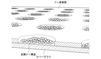
- FIG. 3 is a schematic diagram of an example of a SERS chip in which metal nanostructures are solid-phased.
- FIG. 4 is a schematic cross-sectional view explaining each step of the manufacturing method of the SERS chip.
- FIG. 5 is a scattering image of a SERS chip in which silver nanoparticles are immobilized on a microchamber array used in Examples.
- FIG. 6 is a schematic diagram of an optical system of a wide-field Raman microscope used in Examples. The image shown on the left side of FIG.
- FIG. 7 is a SERS image of a sample in which a mixed solution of acetylcholinesterase (AChE) and acetylthiocholine was enclosed in a SERS chip in the example.
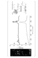
- the graph shown in the center of FIG. 7 is the SERS spectra in chamber A and chamber B in the SERS image.
- the figure shown on the right side of FIG. 7 is a schematic diagram of decomposition of acetylthiocholine by acetylcholinesterase and SERS measurement of the decomposition products.
- the SERS image and the SERS spectrum were acquired with a slit scanning Raman microscope under the conditions of 100 pM acetylcholinesterase and 2 mM acetylthiocholine.
- FIG. 8 is a graph showing the relationship between the acetylcholinesterase (AChE) concentration and the number of bright spots in Examples. The number of bright spots was obtained with a slit scanning Raman microscope.
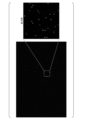
- FIG. 9 is a SERS image of a sample in which a mixed solution of acetylcholinesterase (AChE) and acetylthiocholine was encapsulated in a SERS chip in Example. The SERS image was obtained with a wide-field Raman microscope under the conditions of 10 pM acetylcholinesterase and 2 mM acetylthiocholine.
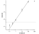
- FIG. 10 is a graph showing the relationship between the acetylcholinesterase (AChE) concentration and the number of bright spots in Examples.
- the number of bright spots was obtained with a wide-field Raman microscope.
- the dotted line in the graph indicates the value obtained by adding three times the standard deviation to the average number of bright spots when acetylcholinesterase is 0M.
- the intersection point of the dotted line and the solid line is regarded as the lower limit of detection.
- the image shown in the upper left of FIG. 11 is a SERS image of a sample in which a mixed solution of acetylcholinesterase (AChE), butyrylcholinesterase (BuChE), MATP+, and butyrylthiocholine was enclosed in a SERS chip in Example.
- the graph shown in the lower left of FIG. 11 is the SERS spectra in chamber A and chamber B in the SERS image.
- the diagrams shown in the upper right of FIG. 11 are schematic diagrams (left) of degradation of MATP + by acetylcholinesterase (AChE) and SERS measurement of degradation products, and degradation and degradation products by butyrylcholinesterase (BuChE) butyrylthiocholine.
- the SERS image and the SERS spectrum were obtained with a slit scanning Raman microscope under the conditions of 100 pM each of acetylcholinesterase and butyrylcholinesterase, and 1 mM each of MATP+ and butyrylthiocholine.
- Raman spectroscopic imaging device An example of a Raman spectroscopic imaging apparatus used for measurement of a SERS chip (a microchamber array in which a metal nanostructure is solid-phased in each microchamber; details will be described later) in the present technology will be described.
- a Raman spectroscopic imaging apparatus 100 whose configuration outline is shown in FIG. 1 has a line illumination system and a wide-field illumination system.
- the laser light (excitation laser) emitted from the laser light source 101 passes through the mirror 103 ⁇ cylindrical lens 104 ⁇ lens 105 ⁇ dichroic filter 109 ⁇ objective lens 112 in order to illuminate the sample 113.
- a laser beam from a laser light source 101 is shaped into a line by a cylindrical lens 104 .
- Raman scattered light from the sample 113 passes through the objective lens 112 ⁇ the dichroic filter 109 ⁇ the lens 111 in this order, and forms an image on the CCD 116 along the slit 114 of the spectroscope 115 .
- Line illumination systems detect the spectrum in parallel to speed it up.
- the laser light emitted from the laser light source 101 passes through the flip mirror 102 ⁇ lens 107, mirror 108, flip mirror 106 ⁇ dichroic filter 109 ⁇ objective lens 112 in order to illuminate the sample 113.
- the Raman light from the sample 113 passes through the objective lens 112 ⁇ dichroic filter 109 ⁇ flip mirror 110 ⁇ lens 117 ⁇ narrow line width bandpass filter 118 in order, and forms an image on the sCMOS of the two-dimensional detector 119.
- a narrow linewidth bandpass filter 118 matched to the position of the Raman peak specific to the degradation products of the substrate is placed in the imaging optics for widefield illumination. Using the angular dependence of the transmission band, scattering images are obtained at the top and tail of the Raman peak of the decomposition product, and the SERS light intensity in each chamber is quantified from the difference.
- Fig. 2 shows an example of approximate measurement time for each lighting type. With wide-field illumination, it is expected to analyze 100 or more per second.
- the scattering intensity derived from the enzymatic reaction product can be selectively extracted by adjusting the angle of the narrow linewidth bandpass filter.
- SERS chip An example of a microchamber array (SERS chip) in which metal nanostructures are solid-phased in microchambers used in the present technology will be described. However, in the present technology, a droplet can be used instead of the microchamber array, but this will be described separately.
- the SERS chip according to this technology can obtain uniform SERS light intensity. Ensuring uniformity is to form metal nanostructures uniformly within each chamber. The reason is that strong SERS light is generated in minute gaps (gaps) in the metal nanostructure. It is possible to control the formation of metal nanostructures in the chamber and form numerous gap structures to stabilize the degree of amplification.
- An example of the microchamber is a cylindrical shape with a glass bottom and a fluororesin periphery. As shown in FIG. 3, it is preferable to chemically modify the glass portion of the bottom surface of the microchamber so that the metal nanostructure covers the entire bottom surface of the chamber. The sensitivity and uniformity can be further improved by optimizing the metal species, shape, size, forming conditions, excitation wavelength, chamber volume, etc. that constitute the metal nanostructure.
- the SERS chip described above can be manufactured, for example, as follows.
- a substrate 510 is prepared.
- Examples of materials for the substrate 510 include glass and resin.
- Glass is not particularly limited. Examples of glass include quartz glass, borosilicate glass, soda-lime glass, and the like.
- resins examples include polyethylene, polypropylene, polystyrene, polycarbonate, cyclic polyolefin, and acrylic.
- polycarbonate is also used as a material for inexpensive mass-producible CDs and DVDs, and is suitable from the viewpoint of low-cost production of microchamber arrays.
- the material of the substrate 510 is preferably glass or polycarbonate, more preferably glass.
- a film 700 is laminated on the surface of the substrate 510. Then, as shown in FIG. 4(b), a film 700 is laminated on the surface of the substrate 510. Then, as shown in FIG. 4(b), a film 700 is laminated on the surface of the substrate 510. Then, as shown in FIG. 4(b), a film 700 is laminated on the surface of the substrate 510. Then, as shown in FIG. 4(b), a film 700 is laminated on the surface of the substrate 510.
- Materials for the film 700 include fluorine-based resins, cyclic polyolefins, silicone-based resins, and the like.
- the thickness of the membrane 700 is not particularly limited, but can be set as appropriate in consideration of the volume of the microchamber.
- a resist film 710 is laminated on the surface of the film 700. Then, as shown in FIG. 4(c), a resist film 710 is laminated on the surface of the film 700. Then, as shown in FIG. Subsequently, using a mask having a microchamber array pattern, the resist film 710 is exposed by irradiating active energy rays with an exposure machine. Subsequently, development is performed with a developer to remove the resist film 710 from the portions where the microchambers are to be formed.
- the film 700 masked with the resist film 710 is etched to form microchambers 530 in the film 700 .
- the substrate is washed to remove the resist film 710 to obtain an array of microchambers 530 .
- a microchamber array having a plurality of microchambers is obtained.
- a metal nanostructure is solid-phased on the bottom surface of the well 530 of the fabricated microchamber array.
- a cationic functional group is introduced to the bottom surface of the microchambers 530 of the microchamber array.
- a dispersion of metal nanoparticles and trifluoroacetic acid, which is an aggregation accelerator, are mixed and dropped into the microchamber to form aggregates of negatively charged metal nanoparticles on the bottom surface of the microchamber.
- microchamber array is obtained in which metal nanostructures, which are aggregates of metal nanoparticles, are solid-phased on the bottom of the microchambers.
- the volume of the microchamber is not particularly limited, but is preferably 1aL to 1nL, more preferably 1fL to 1pL.
- "a" (ato), “f” (femto), “p” (pico) and “n” (nano) represent 10 -18 , 10 -15 , 10 -12 and 10 -9 respectively. is a prefix.
- examples of metal nanostructures include metal nanoparticle aggregates obtained by aggregating metal nanoparticles in the presence of an aggregating agent, and regular array structures of metal nanostructures using the closest-packed array of polystyrene beads as a template. be done.
- Metal nanostructures also include metal nanodot arrays based on anodized porous alumina.
- the metal type of the metal nanostructure is not particularly limited, but at least one selected from the group consisting of silver, gold, copper, platinum, palladium, aluminum and titanium is preferable, and the group consisting of silver, gold, platinum and palladium. At least one selected from is more preferable, silver or gold is more preferable, and silver is still more preferable. Two or more different metals may be used in combination. Also, an alloy of two or more metals may be used. Core-shell type particles of two or more kinds of metals can also be used as the metal nanoparticles.
- the shape of the metal nanoparticles when forming the metal nanostructures using the metal nanoparticles is not particularly limited, but examples thereof include spherical, subspherical, rod-shaped, cubic, elliptical, triangular, bipyramidal, stars, etc. Two or more kinds of metal nanoparticles having different shapes may be used in combination.
- the average particle size of the primary particles of the metal nanoparticles is not particularly limited, but is preferably 1 to 1500 nm, more preferably 1 to 500 nm, even more preferably 10 to 100 nm.
- the volume of the primary particles of the metal nanoparticles is not particularly limited, but is preferably 1 nm 3 to 1 ⁇ m 3 .
- the metal nanoparticles may be metal nanoparticle aggregates in which multiple metal nanoparticles aggregate. Aggregates of metal nanoparticles can be produced, for example, by treating metal nanoparticles (primary particles) with an aggregation promoter such as trifluoroacetic acid to aggregate them.
- an aggregation promoter such as trifluoroacetic acid
- the metal nanoparticles can be produced by a conventionally known method.
- metal nanoparticles as aggregates, a myriad of fine gaps between adjacent particle pairs are formed, and the number of molecules present in the gaps can be increased, so Raman scattering is further enhanced, resulting in increased sensitivity. It becomes easier to improve.
- the number of microchambers per microchamber array is not particularly limited, but is preferably 100 or more, more preferably 1,000 or more, and even more preferably 10,000 or more.
- the upper limit of the number of microchambers per microchamber array is not particularly limited, it is preferably 10,000,000 or less because it is undesirable to take too much time to measure the brightness of the bright spots and count the number.
- the enzymatic reaction of the selective substrate is performed for each microreaction space (microchamber or droplet) enclosing an enzyme of one molecule or less, the selective substrate of the enzyme, and the metal nanostructure.
- the surface-enhanced Raman scattering intensity derived from the product or the selective substrate is measured, and the surface-enhanced Raman scattering intensity changes by a preset value or more, or the number of reaction spaces that is a preset threshold value or more or a threshold value or less.
- the function of the enzyme (decomposition of the substrate) is captured for each molecule using a minute reaction space, and the number of enzyme molecules can be directly calculated from the number of minute reaction spaces in which changes are observed. By counting, the enzyme concentration in the specimen can be measured more quantitatively and with high sensitivity.
- a first embodiment of the enzyme measurement method of the present technology includes a mixed solution preparation step of preparing a mixed solution containing an enzyme and a selective substrate of the enzyme, and a plurality of microchambers in which metal nanostructures are immobilized.
- a step of measuring the number of bright spots for measuring the number of microchambers that are equal to or greater than or equal to or less than a preset threshold the enzymatic reaction product exhibits a structure different from that of the selective substrate, and the Raman peak can distinguish between the enzymatic reaction product and the selective substrate.
- Examples of the enzymes include acetylcholinesterase, butyrylcholinesterase, phospholipase, elastase, amylase, and the like.
- Acetylcholinesterase is present in nerve tissue, red blood cells, etc., and is one of the neurotransmitters of cholinergic nerves (parasympathetic nerves, motor nerves, sympathetic nerve centers to ganglia). decompose into Although AChE itself is acetylated by Ach degradation and deactivated, deacetylation occurs in several milliseconds and it regains activity.
- Butyrylcholinesterase (BuChE) is synthesized in the human liver, is present in serum, etc., and degrades various choline esters including ACh.
- the selective substrate of the enzyme exhibits a structure different from that of the enzymatic reaction product of the selective substrate, and is capable of distinguishing between the enzymatic reaction product and the selective substrate by the Raman peak.
- the enzymatic reaction product has a molecular structure capable of interacting with the metal nanostructure.
- the selective substrate of the enzyme can be appropriately selected according to the type of enzyme.
- -acetylthiomethylpiperidinium The BuChE hydrolysis products of BTC are thiocholine and butyric acid, and the AChE hydrolysis products of MATP+ are 1,1-dimethyl-4-mercaptomethylpiperidinium and acetic acid.
- Thiocholine and 1,1-dimethyl-4-mercaptomethylpiperidinium are preferable because they have a thiol group (mercapto group) in the molecule and are easily trapped on the surface of the metal nanoparticles described below.
- Thiocholine and 1,1-dimethyl-4-mercaptomethylpiperidinium are also preferred because they are a combination of compounds that can be easily distinguished from the Raman scattering spectrum.
- water is preferable as the solvent or dispersion medium for the mixed liquid.
- the water is preferably ultrapure water such as milli-Q water or ultrafiltered water (UF water), but the water in which the enzyme or selective substrate is dissolved or dispersed may be used as the solvent or dispersion medium for the mixed solution. .
- the mixed solution may contain a surfactant in addition to the enzyme, selective substrate and solvent.
- the type of surfactant is not particularly limited as long as it does not inhibit the reaction between the enzyme and its selective substrate.
- examples include Triton X-100 (t-octylphenoxypolyethoxyethanol; Triton X-100). to be
- the concentration of the surfactant is not particularly limited as long as it does not inhibit the reaction between the enzyme and its selective substrate.
- the mixed solution is used so that there is no more than one enzyme molecule per microchamber. If appropriate, the mixture may be diluted and used. Water is preferred as the solvent or dispersion medium used for dilution. As water, ultrapure water such as Milli-Q water and ultrafiltration water (UF water) is preferable.
- Array preparation step In the array preparation step, a metal nanostructure-immobilized microchamber array (SERS chip) having a plurality of microchambers in which metal nanostructures are immobilized is prepared.
- SERS chip metal nanostructure-immobilized microchamber array
- the SERS chip can be manufactured, for example, according to the manufacturing method described above.
- the mixed solution enclosing step In the mixed solution enclosing step, the mixed solution is enclosed in each of the plurality of microchambers of the SERS chip prepared in the array preparation step so that the number of molecules of the enzyme is one or less. That is, the number of molecules of the enzyme contained in one microchamber is one or less.
- the mixed solution prepared in the mixed solution preparation step may be used after being diluted as appropriate.
- the mixed liquid in the SERS chip for example, after distributing the mixed liquid to each microchamber, oil or liquid paraffin is layered and enclosed in the mixed liquid in the microchambers.
- the SERS chip described above has a high water repellency because the upper surface of the SERS chip is coated with a fluororesin.
- a reaction product (enzyme reaction product) is generated between the enzyme and its selective substrate. Since the volume of the mixed solution is small, the enzymatic reaction products are located near the metal nanostructures in the mixed solution.
- LSPR localized surface plasmon resonance
- SERS Surface-enhanced Raman scattering enhances the Raman scattering intensity of molecules in close proximity to the surface of metal nanoparticles by orders of magnitude.
- the enzymatic reaction product may exist in the vicinity of the metal nanostructure, but may be adsorbed or bound to the surface of the metal nanostructure.
- the Raman scattered light can be enhanced and the sensitivity can be further improved.
- a method for enclosing the mixed liquid in the microchamber is, for example, encapsulation with oil.
- Oils include, but are not limited to, inert oils such as fomblin, mineral oil, hexadecane, 3M Fluorinert FC-40, 3M Fluorinert FC-70.
- the surface-enhanced Raman scattering intensity derived from the enzyme reaction product of the selective substrate or the selective substrate has changed by a preset value or more, or is a preset threshold value or more or a threshold value or less. Count the number of chambers.
- a Raman scattering image may be obtained at the bottom of the Raman peak of the enzyme reaction product or the selective substrate, and the surface-enhanced Raman scattering light intensity may be quantified from the difference between the top and bottom.
- the number of microchambers whose surface-enhanced Raman scattering intensity has changed to a preset value or more, or whose surface-enhanced Raman scattering intensity is greater than or equal to a preset threshold or less than a threshold is counted.
- the preset value or threshold is determined, for example, by using a sample containing an enzyme and a selective substrate of the enzyme and a sample that does not contain at least one of the enzyme and the selective substrate of the enzyme.
- the surface-enhanced Raman scattering light intensity derived from the enzymatic reaction product or the selective substrate can be measured and experimentally obtained as a value capable of distinguishing between the two samples.
- a method for determining the preset value or threshold is not particularly limited, and can be determined using a general statistical method, for example. By comparing the predetermined value or threshold value and the surface-enhanced Raman scattering light intensity derived from the selective substrate or the enzymatic reaction product of the selective substrate measured in the step of measuring the number of bright spots, the enzyme is contained in the microchamber. It is possible to judge whether or not
- the narrow linewidth bandpass filter may be composed of a single narrow linewidth bandpass filter, or may be composed of two or more bandpass filters in combination to narrow the transmission band.
- the narrow linewidth bandpass filter may adjust the transmission band by using the angular dependence of the transmission band.
- a first embodiment of an enzyme measurement method of the present technology includes a mixed solution preparation step of preparing a mixed solution containing multiple types of enzymes and multiple types of selective substrates corresponding to the multiple types of enzymes, and a metal nanostructure an array preparation step of preparing a metal nanostructure-immobilized microchamber array having a plurality of microchambers immobilized with a body; a mixed solution encapsulating step of enclosing the mixed solution so that the number of molecules is 1 or less; and measuring the number of microchambers in which the surface-enhanced Raman scattering intensity derived from the selective substrate has changed to a preset value or more, or has a preset threshold value or more or a threshold value or less.
- the enzymatic reaction product exhibits a structure different from that of the selective substrate
- the Raman peak distinguishes the enzymatic reaction product from the selective substrate
- the plurality of types of enzymatic reaction products are different from each other.
- the Raman peaks exhibit different structures and can distinguish multiple types of the enzymatic reaction products or the selective substrates.
- the basic example of the first embodiment described above is that in the mixed solution preparation step, a mixed solution containing multiple types of enzymes and multiple types of selective substrates corresponding to the multiple types of enzymes is prepared; In the step, the mixed solution is enclosed in each of the plurality of microchambers so that the number of molecules of at least one of the plurality of types of enzymes is 1 or less; The difference is in identifying the enzymatic reaction product or the selective substrate, but the other points are substantially the same.
- a second embodiment of the enzyme measurement method of the present technology includes a mixed solution preparation step of preparing a mixed solution containing an enzyme and a selective substrate of the enzyme, and a plurality of microchambers in which metal nanostructures are immobilized.
- the enzymatic reaction product exhibits a structure different from that of the selective substrate, and the Raman peak can distinguish between the enzymatic reaction product and the selective substrate.
- the step of measuring the number of bright points of the first embodiment is temporal measurement in which surface-enhanced Raman scattering intensity derived from an enzyme reaction product or a selective substrate is measured for each of the plurality of microchambers over time. process has been changed. Others are substantially the same as those of the first embodiment.
- Measuring the enzymatic activity as a scattering intensity change per unit time by measuring the surface-enhanced Raman scattering intensity derived from the enzymatic reaction product or the selective substrate over time for each of the plurality of microchambers in the time course measurement step. can be done. By measuring the enzyme activity, it is also possible to obtain information such as what the multimeric enzyme is.
- a second embodiment of the enzyme measurement method of the present technology includes a mixed solution preparation step of preparing a mixed solution containing multiple types of enzymes and multiple types of selective substrates corresponding to the multiple types of enzymes, and a metal nanostructure an array preparation step of preparing a metal nanostructure-immobilized microchamber array having a plurality of microchambers immobilized with a body; a mixed solution encapsulating step of enclosing the mixed solution so that the number of molecules is 1 or less;
- the enzyme measurement method may include a temporal measurement step of temporally measuring the surface-enhanced Raman scattering intensity derived from the selective substrate for each of the plurality of microchambers.
- the Raman peak distinguishes the enzymatic reaction product from the selective substrate, and the plurality of types of enzymatic reaction products are different from each other.
- the Raman peaks exhibit different structures and can distinguish multiple types of the enzymatic reaction products or the selective substrates.
- the basic example of the second embodiment described above is that in the mixed solution preparation step, a mixed solution containing multiple types of enzymes and multiple types of selective substrates corresponding to the multiple types of enzymes is prepared; In the step, the mixed solution is enclosed in each of the plurality of microchambers so that the number of molecules of at least one of the plurality of types of enzymes is 1 or less; The difference is in the identification of the product or the selective substrate, but the rest is substantially the same.
- a third embodiment of the enzyme measurement method of the present technology includes a mixed solution preparation step of preparing a mixed solution containing an enzyme, a selective substrate of the enzyme, and a metal nanostructure; a droplet splitting step of splitting into a plurality of droplets containing no more than one; and measuring the number of droplets whose surface-enhanced Raman scattering intensity has changed to a preset value or more, or whose surface-enhanced Raman scattering intensity is above or below a preset threshold.
- the enzymatic reaction product exhibits a structure different from that of the selective substrate, and the Raman peak can distinguish between the enzymatic reaction product and the selective substrate.
- the first embodiment of the present technology is that a mixed solution containing an enzyme, a selective substrate of the enzyme, and a metal nanostructure is used, and instead of enclosing the mixed solution in a microchamber, one molecule of the enzyme
- the difference is that the droplets are divided into a plurality of droplets containing one or less droplets.
- a method of division a method of emulsifying by injecting the mixed liquid into the oil with a jet, and the like can be mentioned.
- Oils include, but are not limited to, inert oils such as fomblin, mineral oil, hexadecane, 3M Fluorinert FC-40, and 3M Fluorinert FC-70.
- the Raman scattering intensity of each droplet may be measured two-dimensionally by spreading the droplet on a plane, or one-dimensionally measuring the droplet one by one.
- a third embodiment of the enzyme measurement method of the present technology includes a mixed solution preparation step of preparing a mixed solution containing a plurality of types of enzymes and a plurality of types of selective substrates corresponding to the plurality of types of enzymes; a droplet splitting step of splitting into a plurality of droplets containing at least one molecule of at least one of the plurality of types of enzymes, and illuminating the plurality of droplets with excitation light to illuminate the
- the surface-enhanced Raman scattering intensity derived from the enzyme reaction product of the selective substrate or the selective substrate has changed to a preset value or more, or the number of droplets whose intensity is a preset threshold value or more or a threshold value or less is measured.
- It may be a measuring method of an enzyme including a scoring step. wherein the enzymatic reaction product exhibits a structure different from that of the selective substrate, the Raman peak distinguishes the enzymatic reaction product from the selective substrate, and the plurality of types of enzymatic reaction products are different from each other.
- the Raman peaks exhibit different structures and can distinguish multiple types of the enzymatic reaction products or the selective substrates.
- the third embodiment is adapted to multiple types of enzymes and substrates.
- a fourth embodiment of the enzyme measurement method of the present technology includes a mixed solution preparation step of preparing a mixed solution containing an enzyme, a selective substrate of the enzyme, and a metal nanostructure; a droplet splitting step of splitting into a plurality of droplets containing no more than one; and a temporal measurement step of temporally measuring the surface-enhanced Raman scattering intensity for each of the plurality of droplets.
- the enzymatic reaction product exhibits a structure different from that of the selective substrate, and the Raman peak can distinguish between the enzymatic reaction product and the selective substrate.
- the step of measuring the number of bright spots in the third embodiment is changed to a temporal measurement step of temporally measuring the surface-enhanced Raman scattering intensity derived from the enzymatic reaction product for each of the plurality of droplets. ing. Others are substantially the same as those of the third embodiment.
- the enzyme activity can be measured as a change in scattering intensity per unit time. By measuring the enzyme activity, it is also possible to obtain information such as what the multimeric enzyme is.
- a fourth embodiment of the enzyme measurement method of the present technology includes a mixed solution preparation step of preparing a mixed solution containing a plurality of types of enzymes and a plurality of types of selective substrates corresponding to the plurality of types of enzymes; a droplet splitting step of splitting into a plurality of droplets containing at least one molecule of at least one of the plurality of types of enzymes, and illuminating the plurality of droplets with excitation light to illuminate the a temporal measurement step of temporally measuring an enzymatic reaction product of a selective substrate or surface-enhanced Raman scattering intensity derived from the selective substrate for each of the plurality of droplets. .
- the Raman peak distinguishes the enzymatic reaction product from the selective substrate, and the plurality of types of enzymatic reaction products are different from each other.
- the Raman peaks exhibit different structures and can distinguish multiple types of the enzymatic reaction products or the selective substrates.
- the fourth embodiment is adapted to multiple types of enzymes and substrates.
- kits The present technology also includes the above-described SERS chip (a metal nanostructure-immobilized microchamber array having a plurality of microchambers in which metal nanostructures are immobilized), and the above-described first or second embodiment. Also provided are kits containing a protocol describing the procedure for measuring the enzyme. The kit may contain standard reagents and other components in addition to the SERS chip and protocol.
- One embodiment of the Raman scattering image capturing method of the present technology is to align the transmission wavelength band of a narrow linewidth bandpass filter with the top of the Raman peak of the target molecule, irradiate the sample with a laser beam expanded to the entire field of view, and This is a Raman scattering image capturing method for capturing a Raman scattering image with a two-dimensional photodetector during irradiation.
- the transmission wavelength band of the narrow linewidth bandpass filter may be matched with the bottom of the Raman peak of the target molecule.
- the target molecules are arranged in the plurality of microchambers of a microchamber array having a plurality of microchambers.
- the microchamber array preferably has metal nanostructures immobilized in the plurality of microchambers.
- the microchamber array for example, the microchamber array of the present technology described above is preferably used, and the target molecule is arranged in each microchamber.
- the target molecule is preferably arranged on the metal nanostructure.
- the Raman scattering image capturing method of the present embodiment can be implemented, for example, in the same manner as the enzyme measurement method of the present technology described above.
- narrow linewidth bandpass filter for example, the same one as that used in the method for measuring the enzyme of the present technology described above can be used.
- target molecule examples include, but are not limited to, the enzymes described above.
- One embodiment of the method for measuring a target molecule of the present technology is to align the transmission wavelength band of a narrow linewidth bandpass filter with the top of the Raman peak of the target molecule, irradiate the sample with a laser beam expanded to the entire field of view, and perform laser irradiation.
- a method for measuring a target molecule using Raman scattering in which a Raman scattering image is captured by a two-dimensional photodetector and the concentration distribution of the target molecule is extracted from the obtained Raman scattering image.
- the transmission wavelength band of the narrow linewidth bandpass filter may be adjusted to the bottom of the Raman peak of the target molecule.
- the concentration distribution of the target molecule is obtained by taking the difference between the Raman scattering images photographed in the top transmission wavelength band and the bottom transmission wavelength band of the Raman peak of the target molecule. Extraction is preferred.
- the target molecule is preferably arranged in the plurality of microchambers of a microchamber array having a plurality of microchambers.
- the microchamber array preferably has metal nanostructures immobilized in the plurality of microchambers.
- the microchamber array for example, the microchamber array of the present technology described above is preferably used, and the target molecule is arranged in each microchamber.
- the target molecule In the method for measuring the target molecule of the present embodiment, it is preferable to dispose the target molecule on the metal nanostructure.
- the method for measuring the target molecule of the present embodiment can be implemented, for example, in the same manner as the method for measuring the enzyme of the present technology described above.
- narrow linewidth bandpass filter for example, the same one as that used in the method for measuring the enzyme of the present technology described above can be used.
- target molecule examples include, but are not limited to, the enzymes described above.
- This technology can be suitably applied to liquid biopsy. Specifically, for example, by measuring enzymes in liquid components such as blood, detailed information on human cancer can be obtained more quickly and with less invasiveness.
- cancer-related enzymes include thymidine kinase, galactosyltransferase, and the like.
- This technique introduces the concept of digital detection into SERS spectroscopy, and is an ultra-sensitive enzyme concentration measurement technique in which the number of enzyme molecules is plotted on the vertical axis.
- concentration quantification of target molecules has been performed with scattered light intensity as the vertical axis.
- This technology is unique in that it fuses spectroscopic measurement technology and bio-single-molecule measurement technology.
- a fluorescent substrate has been used to measure the activity of a single enzyme molecule.
- This technology captures the Raman scattering light of the enzymatic reaction product itself of the substrate, and can simultaneously quantify multiple substrate degradation reactions of one molecule of enzyme by utilizing the unlabeled and narrow linewidth spectrum.
- this technology removes the barrier of activity inhibition by fluorescently labeled substrates, broadens the types of enzymes that can be measured, and has the unprecedented advantage of being able to identify enzyme types. .
- Step S1 A cover glass of 24 mm x 32 mm was placed on a glass stand and immersed in an 8N potassium hydroxide aqueous solution.
- Step S2 Ultrasonic treatment (90 minutes) was performed.
- - Process S3 It left still (1 day).
- - Step S4 Rinse with pure water.
- Step S5 Water droplets on the glass were removed by an air blow.
- Step S6 A fluororesin (9% Cytop (fluororesin, manufactured by AGC)) was dropped onto the glass.
- Step S7 Spin coating was performed at a rotation speed of 1000 rpm for 30 seconds.
- Step S8 Bake at 80°C for 10 minutes and at 180°C for 1 hour.
- Step S9 A positive photoresist (AZ P4620 (manufactured by AZ Electronic Materials)) was dropped on the Cytop-coated glass.
- - Step S10 Spin coating was performed at a rotation speed of 7500 rpm for 30 seconds.
- - Step S11 Bake at 100°C for 5 minutes.
- - Step S12 Allowed to stand (5 minutes or more, humidity of 60% or more).
- Step S13 A chromium mask (holes with a diameter of 1.8 ⁇ m arranged in an array at a pitch of 8 ⁇ m) was brought into close contact with the resist-coated glass.
- - Step S14 UV exposure for 20 seconds.
- Step S15 The exposed cover glass was placed on a glass stand and immersed in a developer (AZ300 MIF (manufactured by AZ Electronic Materials)) for 90 seconds.
- - Step S16 Rinse with pure water.
- Step S17 Dry etching was performed by a reactive ion etching (RIE) apparatus using oxygen gas (the exposed Cytop without resist protection was removed on the glass).
- RIE reactive ion etching
- Step S18 The cover glass was placed on a glass stand and immersed in acetone (to remove the resist).
- - Step S19 Ultrasonic treatment (90 seconds) was performed.
- - Step S20 Immerse in isopropanol.
- - Process S21 It left still (90 seconds).
- - Step S22 Rinse with pure water.
- Step S23 Water droplets on the glass were removed by an air blow.
- - Step S24 The diameter and depth of the Cytop hole were confirmed with a laser microscope.
- step S7 The rotation speed of step S7 was adjusted between 1000 and 7500 rpm
- step S10 The rotation speed in step S10 was adjusted between 1000 and 7500 rpm.
- the diameter and pitch of the photomask in step S13 are not limited to those described above.
- the chamber in step S24 is assumed to have a diameter of 0.1 to 100 ⁇ m and a depth of 0.01 to 100 ⁇ m.
- the volume in this case is roughly 1aL to 1nL.
- the microchamber array had a diameter of 3.2 ⁇ m, a depth of 1.6 ⁇ m, and a pitch of 8 ⁇ m.
- the microchamber volume was approximately 13 fL.
- microchamber array produced by the above procedure may be referred to as a "device”.
- Step 1 Glass hydrophilic treatment
- Step 2 Ultrasonic treatment (20 minutes) was performed.
- Process 3 It left still (20 minutes).
- Step 4 Rinse with Milli-Q water.
- Step 16 Water droplets on the device were removed by an air blow.
- Step 17 20 ⁇ L of 40 nm silver nanoparticle dispersion and 20 ⁇ L of 0.03% trifluoroacetic acid (TFA) were mixed and dropped onto the device (TFA was added to promote the formation of aggregates of silver fine particles. rice field).
- Step 18 Placed on an aluminum block cooled on ice while the liquid droplets were placed thereon.
- - Process 19 It left still (1 minute).
- Step 20 While the liquid droplets were placed, it was housed in a high-humidity/light-shielding box and stored in a refrigerator (4°C).
- - Process 21 It left still (1 day or more). The fabrication of the SERS chip has been completed.
- the silver nanoparticle dispersion in step 17 is assumed to have a diameter of 1 to 1500 nm.
- Gold, copper, platinum, palladium, aluminum, titanium, etc. can also be used as other metal species. Alloys of these, core-shell structures, and the like can also be used. Various shapes such as spheres, rods, ellipses, triangles, cubes, bipyramids, and stars can be used for the metal nanoparticles.
- Fig. 5 is a scattering image of a SERS chip in which aggregates of silver nanoparticles are immobilized on a microchamber array.
- the surfactant in step 23 was 100 ⁇ M Triton-X in this example.
- Other surfactants can also be used without particular limitation.
- the oil in step 24 was Fomblin in this example.
- Other oils are not particularly limited and can be used.
- other than Fomblin mineral oil, hexadecane, 3M Fluorinert FC-40 (manufactured by 3M), 3M Fluorinert FC-70 (manufactured by 3M) and the like can be used as the oil.
- step 25 in addition to absorption by filter paper, a method of sucking the solution with a pipette, a method of flushing with oil using a flow path, etc. can be used without particular limitation.
- Step 32 The irradiation of the laser light and the exposure of the two-dimensional photodetector were stopped.
- Step 33 The angle of the narrow linewidth bandpass filter was adjusted to match the transmission wavelength band with the bottom (tail) of the Raman peak of the reaction product.
- Step 34 The sample was irradiated with laser light expanded to the entire field of view (the irradiation time was the same as in step 30).
- Step 35 During laser irradiation, a scattered image of the SERS chip was taken with a two-dimensional photodetector (CMOS camera, CCD camera, etc.) (same exposure time as step 31).
- Step 36 The irradiation of the laser light and the exposure of the two-dimensional photodetector were stopped.
- Step 37 The sample stage of the microscope was moved.
- Step 38 Steps 29 to 37 were repeated (in step 37, the sample table was moved in a tiled manner).
- the exposure time of the detector in steps 31 and 34 is preferably 1 millisecond to 100 seconds. In this example, it was 2 seconds.
- step 37 scanning was performed 30 times at a vertical pitch of 60 ⁇ m and 9 times at a horizontal pitch of 135 ⁇ m, and a total of 270 points were imaged.
- FIG. 6 is a schematic diagram of the optical system of a wide-field Raman microscope.
- Step 39 The difference between the images captured in step 30 (peak top) and step 32 (beak bottom) was obtained for each position of the sample stage.
- Step 40 The differential images obtained in step 39 were arranged in tiles according to the movement order of the sample stage.
- Step 41 The number of microchambers (bright spots) brighter than the set threshold was counted.
- Step 27-s The SERS chip was placed on the sample stage of the microscope. • Step 28-s: The objective lens was focused on the bottom surface of the microchamber. Step 29-s: The sample was irradiated with a linear (y-direction) laser beam (several milliseconds to several tens of seconds).
- Step 29-s The sample was irradiated with a linear (y-direction) laser beam (several milliseconds to several tens of seconds).
- Step 29-s The sample was irradiated with a linear (y-direction) laser beam (several milliseconds to several tens of seconds).
- CMOS camera, CCD camera, etc.) connected to the spectrometer captured a scattered spectral image (y- ⁇ ) of the SERS chip (exposure time: several milliseconds to tens of seconds).
- Step 31-s The irradiation of the laser light and the exposure of the two-dimensional photodetector were stopped.
- Step 32-s The sample stage of the microscope was moved in a direction (x direction) perpendicular to the laser line.
- Step 33-s Steps 29-s to 32-s were repeated.
- Step 34-s The scattering spectroscopic image (y- ⁇ ) acquired while scanning in the x-direction was reconstructed into xy- ⁇ data.
- Step 35-s xy- ⁇ 1 and xy- ⁇ 3 were extracted with the ⁇ direction aligned with the top ( ⁇ 1) and bottom ( ⁇ 3) of the Raman peak of the reaction product, respectively.
- Step 36-s The difference between xy- ⁇ 1 and xy- ⁇ 3 was taken.
- Step 37-s The number of microchambers (bright spots) brighter than the set threshold was counted.
- the scanning pitch (x direction) in step 32-s is 0.5 ⁇ m in this example.
- the length (y-direction) of the linear laser was 140 ⁇ m in this example.
- the SERS spectra derived from 1,1-dimethyl-4-mercaptomethylpiperidinium, which is an enzymatic reaction product by acetylcholinesterase, and thiocholine, which is an enzymatic reaction product by butyrylcholinesterase, are shown. observed in different microchambers.
- the enzyme concentration in the sample can be quantified with high sensitivity, the function of the enzyme (substrate decomposition) can be detected more quantitatively for each molecule. Furthermore, substrates with different reactivities can be used to simultaneously identify and quantify a plurality of enzymatic activities. INDUSTRIAL APPLICABILITY According to the present invention, it becomes possible to quantify the concentration of an enzyme in a sample, which has been impossible due to lack of sensitivity and discriminative ability, and can widely contribute to medical and biological research.
- DESCRIPTION OF SYMBOLS 100 High-speed Raman spectral imaging apparatus 101... Laser light source 102, 106, 110... Flip mirror for optical path switching 103, 108... Mirror, 104... Cylindrical lens, 105, 107, 111, 117... Lens, 109... Dichroic filter , 114... Slit, 115... Spectroscope, 116... CCD, 118... Narrow line width bandpass filter, 119... sCMOS, 112... Objective lens, 113... Sample, 510... Substrate, 530... Well, 700... Film, 710... resist film
Abstract
This enzyme measurement method includes: a liquid mixture preparation step in which a liquid mixture containing an enzyme and a selective substrate for the enzyme is prepared; an array preparation step in which a microchamber array with immobilized metal nanostructures that includes a plurality of microchambers in which metal nanostructures are immobilized is prepared; a mixture filling step in which the plurality of microchambers are filled with the liquid mixture so that no more than one molecule of the enzyme is present in each of the plurality of microchambers; and a bright point quantity measurement step in which the microchamber array with immobilized metal nanostructures is illuminated with excitation light and the number of microchambers in which the surface-enhanced Raman scattering intensity derived from an enzymatic reaction product of the selective substrate or from the selective substrate has changed by a value equal to or greater than a preset value is measured, or the number of microchambers in which the surface-enhanced Raman scattering intensity is equal to or greater than a preset threshold value or equal to or less than the threshold value is measured.
Description
本発明は、酵素の測定方法、マイクロチャンバーアレイ、キット、ラマン散乱像の撮影方法、及び目的分子の測定方法に関する。本願は、2021年12月8日に、日本に出願された特願2021-199642号に基づき優先権を主張し、その内容をここに援用する。
The present invention relates to an enzyme measurement method, a microchamber array, a kit, a Raman scattering image imaging method, and a target molecule measurement method. This application claims priority based on Japanese Patent Application No. 2021-199642 filed in Japan on December 8, 2021, the content of which is incorporated herein.
酵素は、加水分解や転移などの反応を介し、基質分子の構造を変化させる。生体内には数千種類の酵素が存在し、代謝、吸収、信号伝達などの機能を担う。血液や唾液、尿などの体液中には、臓器等で産生された酵素が微量に含まれ、特定の臓器が機能不全に陥ると、体液中の関連酵素の活性値も低下する。逆に、細胞内の酵素が臓器の炎症や神経細胞の変性などで血液などの体液中へ漏出すると、関連酵素の活性が亢進する。こうした体液中における酵素活性(酵素濃度)の変化は、種々の疾患の進行と相関するため、低侵襲かつ早期の疾患診断指標として重用されている。
Enzymes change the structure of substrate molecules through reactions such as hydrolysis and transfer. Thousands of types of enzymes exist in living organisms and are responsible for functions such as metabolism, absorption, and signal transduction. Body fluids such as blood, saliva, and urine contain trace amounts of enzymes produced in organs, etc., and when a specific organ malfunctions, the activity levels of related enzymes in the body fluids decrease. Conversely, when intracellular enzymes leak into body fluids such as blood due to organ inflammation or degeneration of nerve cells, the activity of related enzymes is enhanced. Since changes in enzyme activity (enzyme concentration) in body fluids correlate with the progression of various diseases, they are often used as minimally invasive and early disease diagnostic indicators.
特許文献1には、フェムトリットルオーダーの大きさのマイクロチャンバーを用いて1分子レベルで酵素活性を検出することが記載されている。
Patent Document 1 describes detection of enzymatic activity at the single-molecule level using a femtoliter-order microchamber.
酵素活性をベースとした疾患診断の拡充にあたり課題となるのが、酵素活性計測技術の改善である。従来、検体中の酵素活性計測は、酵素反応に伴い蛍光又は呈色反応を示す標識基質が用いられてきた。高感度に酵素活性を計測できる重要な手法であるが、一方で、嵩高い標識が酵素反応の妨げとなり、計測困難な酵素種が数多く存在する。さらに、標識基質に複数種の酵素が反応してしまい、混在する酵素群から疾患に寄与する酵素種のみ議論することが困難な場面も多い。酵素を無標識、高感度、かつ複数種の酵素を高精度に識別できる、新たな分析技術の開発が急務である。
A challenge in expanding disease diagnosis based on enzyme activity is the improvement of enzyme activity measurement technology. Conventionally, the measurement of enzyme activity in a sample has used a labeled substrate that exhibits a fluorescence or color reaction accompanying an enzyme reaction. Although this is an important method for measuring enzymatic activity with high sensitivity, there are many enzyme species that are difficult to measure because bulky labels interfere with enzymatic reactions. Furthermore, there are many cases where multiple types of enzymes react with labeled substrates, making it difficult to discuss only enzymes that contribute to disease from among mixed enzyme groups. There is an urgent need to develop new analytical techniques that are label-free, highly sensitive, and capable of distinguishing multiple types of enzymes with high accuracy.
酵素活性を無標識で定量する手法として、ラマン散乱分光法、なかでも高感度化の見込める表面増強ラマン散乱(Surface-enhanced Raman Scattering,SERS)分光法は有望である。SERSは、金属ナノ構造体に形成される光増強場を利用した高感度の振動分光法である。波長より小さなサイズの金属ナノ構造体に光を照射すると、電子の集団励起である局在表面プラズモンが誘起される。ここで金属ナノ構造体の間隔を狭めると、プラズモンどうしが相互作用するようになり、金属ナノ構造体の間に極めて強い増強電場が形成されるようになる。さらにSERS分光法では、この電場増強効果に加え、金属と分子の相互作用に由来する化学効果も見られる。電場増強効果と化学効果により信号光強度が大幅に向上するため、SERS分光法はラマン散乱分光法の高感度化に有望である。さらに、SERS分光法に見られる散乱スペクトルの線幅は、蛍光発光スペクトルと比較して狭い。このため、スペクトルの重なりなく、複数酵素の反応生成物を見分けて、複数同時に多数の酵素活性を計測することも期待できる。しかしながら、緻密な金属ナノ構造体の制御が求められ、定量性と再現性に課題があるため、従来型の散乱強度を縦軸にとるSERS分光法では、検体中の微量な酵素が示す反応生成物を捉え、低濃度域で酵素濃度の定量的な議論を行うことが困難である。
Raman scattering spectroscopy, especially surface-enhanced Raman scattering (SERS) spectroscopy, which is expected to be highly sensitive, is a promising method for quantifying enzyme activity without labeling. SERS is a highly sensitive vibrational spectroscopy that utilizes an optically enhanced field formed in metal nanostructures. When a metal nanostructure with a size smaller than the wavelength is irradiated with light, localized surface plasmons, which are collective excitations of electrons, are induced. Here, if the distance between the metal nanostructures is narrowed, the plasmons will interact with each other, and an extremely strong enhanced electric field will be formed between the metal nanostructures. Furthermore, in SERS spectroscopy, in addition to this electric field enhancement effect, chemical effects derived from metal-molecule interactions are also observed. SERS spectroscopy is promising for increasing the sensitivity of Raman scattering spectroscopy because the signal light intensity is greatly enhanced by the electric field enhancement effect and the chemical effect. Furthermore, the linewidth of the scattering spectrum found in SERS spectroscopy is narrow compared to the fluorescence emission spectrum. Therefore, it is expected that the reaction products of multiple enzymes can be discriminated and the activities of multiple enzymes can be measured at the same time without spectral overlap. However, since control of dense metal nanostructures is required and there are problems with quantification and reproducibility, conventional SERS spectroscopy, in which the vertical axis is the scattering intensity, cannot It is difficult to catch things and make a quantitative discussion of the enzyme concentration in the low concentration range.
本発明は上記事情に鑑みてなされたものであり、試料中の酵素を無標識かつ優れた感度で測定できる技術を提供する。
The present invention has been made in view of the above circumstances, and provides a technique that can measure enzymes in samples without labeling and with excellent sensitivity.
本発明は以下の態様を含む。
[1] 酵素及び前記酵素の選択的基質を含む混合液を準備する混合液準備工程と、
金属ナノ構造体を固相化した複数のマイクロチャンバーを有する金属ナノ構造体固相化マイクロチャンバーアレイを準備するアレイ準備工程と、
前記複数のマイクロチャンバーのそれぞれに前記酵素の分子が1個以下となるように前記混合液を封入する混合液封入工程と、
前記金属ナノ構造体固相化マイクロチャンバーアレイを励起光で照明して、前記選択的基質の酵素反応生成物又は前記選択的基質に由来する表面増強ラマン散乱強度が予め設定した値以上に変化した、又は予め設定した閾値以上若しくは閾値以下であるマイクロチャンバーの個数を計測する輝点数計測工程と、を含み、
前記酵素反応生成物が前記選択的基質とは異なる構造を示し、かつ、ラマンピークで前記酵素反応生成物と前記選択的基質とを区別できる、
酵素の測定方法。
[2] 酵素及び前記酵素の選択的基質を含む混合液を準備する混合液準備工程と、
金属ナノ構造体を固相化した複数のマイクロチャンバーを有する金属ナノ構造体固相化マイクロチャンバーアレイを準備するアレイ準備工程と、
前記複数のマイクロチャンバーのそれぞれに前記酵素の分子が1個以下となるように前記混合液を封入する混合液封入工程と、
前記金属ナノ構造体固相化マイクロチャンバーアレイを励起光で照明して前記選択的基質の酵素反応生成物又は前記選択的基質に由来する表面増強ラマン散乱強度を前記複数のマイクロチャンバー毎に経時的に測定する経時測定工程と、を含み、
前記酵素反応生成物が前記選択的基質とは異なる構造を示し、かつ、ラマンピークで前記酵素反応生成物と前記選択的基質とを区別できる、
酵素の測定方法。
[3] 複数種類の酵素及び前記複数種類の酵素に対応する複数種類の選択的基質を含む混合液を準備する混合液準備工程と、
金属ナノ構造体を固相化した複数のマイクロチャンバーを有する金属ナノ構造体固相化マイクロチャンバーアレイを準備するアレイ準備工程と、
前記複数のマイクロチャンバーのそれぞれに前記複数種類の酵素のうち少なくともいずれか1種類の分子が1個以下となるように前記混合液を封入する混合液封入工程と、
前記金属ナノ構造体固相化マイクロチャンバーアレイを励起光で照明して前記選択的基質の酵素反応生成物又は前記選択的基質に由来する表面増強ラマン散乱強度が予め設定した値以上に変化した、又は予め設定した閾値以上若しくは閾値以下であるマイクロチャンバーの個数を計測する輝点数計測工程と、を含み、
前記酵素反応生成物が前記選択的基質とは異なる構造を示し、ラマンピークで前記酵素反応生成物と前記選択的基質とを区別でき、かつ、複数種類の前記酵素反応生成物は互いに異なる構造を示し、ラマンピークで複数種類の前記酵素反応生成物又は前記選択的基質を区別できる、
酵素の測定方法。
[4] 複数種類の酵素及び前記複数種類の酵素に対応する複数種類の選択的基質を含む混合液を準備する混合液準備工程と、
金属ナノ構造体を固相化した複数のマイクロチャンバーを有する金属ナノ構造体固相化マイクロチャンバーアレイを準備するアレイ準備工程と、
前記複数のマイクロチャンバーのそれぞれに前記複数種類の酵素のうち少なくともいずれか1種類の分子が1個以下となるように前記混合液を封入する混合液封入工程と、
前記金属ナノ構造体固相化マイクロチャンバーアレイを励起光で照明して前記選択的基質の酵素反応生成物又は前記選択的基質に由来する表面増強ラマン散乱強度を前記複数のマイクロチャンバー毎に経時的に測定する経時測定工程と、を含み、
前記酵素反応生成物が前記選択的基質とは異なる構造を示し、ラマンピークで前記酵素反応生成物と前記選択的基質とを区別でき、かつ、複数種類の前記酵素反応生成物は互いに異なる構造を示し、ラマンピークで複数種類の前記酵素反応生成物又は前記選択的基質を区別できる、
酵素の測定方法。
[5] 酵素、前記酵素の選択的基質及び金属ナノ構造体を含む混合液を準備する混合液準備工程と、
前記混合液を前記酵素の分子が1個以下となるように含む複数のドロップレットに分割するドロップレット分割工程と、
前記複数のドロップレットを励起光で照明して前記選択的基質の酵素反応生成物又は前記選択的基質に由来する表面増強ラマン散乱強度が予め設定した値以上に変化した、又は予め設定した閾値以上若しくは閾値以下であるドロップレットの個数を計測する輝点数計測工程と、を含み、
前記酵素反応生成物が前記選択的基質とは異なる構造を示し、かつ、ラマンピークで前記酵素反応生成物と前記選択的基質とを区別できる、
酵素の測定方法。
[6] 酵素、前記酵素の選択的基質及び金属ナノ構造体を含む混合液を準備する混合液準備工程と、
前記混合液を前記酵素の分子が1個以下となるように含む複数のドロップレットに分割するドロップレット分割工程と、
前記複数のドロップレットを励起光で照明して前記選択的基質の酵素反応生成物又は前記選択的基質に由来する表面増強ラマン散乱強度を前記複数のドロップレット毎に経時的に測定する経時測定工程と、を含み、
前記酵素反応生成物が前記選択的基質とは異なる構造を示し、かつ、ラマンピークで前記酵素反応生成物と前記選択的基質とを区別できる、
酵素の測定方法。
[7] 複数種類の酵素、前記複数種類の酵素に対応する複数種類の選択的基質及び金属ナノ構造体を含む混合液を準備する混合液準備工程と、
前記混合液を前記複数種類の酵素のうち少なくともいずれか1種類の分子が1個以下となるように含む複数のドロップレットに分割するドロップレット分割工程と、
前記複数のドロップレットを励起光で照明して前記選択的基質の酵素反応生成物又は前記選択的基質に由来する表面増強ラマン散乱強度が予め設定した値以上に変化した、又は予め設定した閾値以上若しくは閾値以下であるドロップレットの個数を計測する輝点数計測工程と、を含み、
前記酵素反応生成物が前記選択的基質とは異なる構造を示し、ラマンピークで前記酵素反応生成物と前記選択的基質とを区別でき、かつ、複数種類の前記酵素反応生成物は互いに異なる構造を示し、ラマンピークで複数種類の前記酵素反応生成物又は前記選択的基質を区別できる、
酵素の測定方法。
[8] 複数種類の酵素、前記複数種類の酵素に対応する複数種類の選択的基質及び金属ナノ構造体を含む混合液を準備する混合液準備工程と、
前記混合液を前記複数種類の酵素のうち少なくともいずれか1種類の分子が1個以下となるように含む複数のドロップレットに分割するドロップレット分割工程と、
前記複数のドロップレットを励起光で照明して前記選択的基質の酵素反応生成物又は前記選択的基質に由来する表面増強ラマン散乱強度を前記複数のドロップレット毎に経時的に測定する経時測定工程と、を含み、
前記酵素反応生成物が前記選択的基質とは異なる構造を示し、ラマンピークで前記酵素反応生成物と前記選択的基質とを区別でき、かつ、複数種類の前記酵素反応生成物は互いに異なる構造を示し、ラマンピークで複数種類の前記酵素反応生成物又は前記選択的基質を区別できる、
酵素の測定方法。
[9] 前記輝点数計測工程又は前記経時測定工程において、前記混合液を各マイクロチャンバーに封入した前記金属ナノ構造体固相化マイクロチャンバーアレイを、広視野照明で照明し、前記ラマンピークの位置に適合する狭線幅のバンドパスフィルターを用いて、前記酵素反応生成物又は前記選択的基質のラマンピークの波長帯でラマン散乱像を取得し、各マイクロチャンバーの表面増強ラマン散乱光強度と強度の経時変化を定量する、[1]~[4]のいずれかに記載の酵素の測定方法。
[10] 前記酵素反応生成物又は前記選択的基質のラマンピークのトップの波長帯及び前記ラマンピークのボトムの波長帯でラマン散乱像を取得し、両者の差分をとることにより、各マイクロチャンバーの表面増強ラマン散乱光強度と強度の経時変化を定量する、[9]に記載の酵素の測定方法。
[11] 前記輝点数計測工程又は前記経時測定工程において、前記混合液を分割した複数のドロップレットを、広視野照明で照明し、前記ラマンピークの位置に適合する狭線幅のバンドパスフィルターを用いて、前記酵素反応生成物又は前記選択的基質のラマンピークの波長帯でラマン散乱像を取得し、各ドロップレットの表面増強ラマン散乱光強度を定量する、[5]~[8]のいずれかに記載の酵素の測定方法。
[12] 前記酵素反応生成物又は前記選択的基質のラマンピークのトップの波長帯及び前記ラマンピークのボトムの波長帯でラマン散乱像を取得し、両者の差分をとることにより、各ドロップレットの表面増強ラマン散乱光強度を定量する、[11]に記載の酵素の測定方法。
[13] 前記酵素反応生成物がチオール基を有する、[1]~[12]のいずれかに記載の酵素の測定方法。
[14] 前記金属ナノ構造体が金属ナノ粒子の凝集体である、[1]~[13]のいずれかに記載の酵素の測定方法。
[15] 前記酵素が、アセチルコリンエステラーゼ、ブチリルコリンエステラーゼ、ホスホリパーゼ、エラスターゼ及びアミラーゼからなる群から選択される少なくとも1種である、[1]~[14]のいずれかに記載の酵素の測定方法。
[16] アセチルコリンエステラーゼの選択的基質がMATP+であり、ブチリルコリンエステラーゼの選択的基質がブチリルチオコリンである、[15]に記載の酵素の測定方法。
[17] 金属ナノ構造体を固相化した複数のマイクロチャンバーを有するマイクロチャンバーアレイ。
[18] 前記金属ナノ構造体が金属ナノ粒子の凝集体である、[17]に記載のマイクロチャンバーアレイ。
[19] [17]又は[18]に記載のマイクロチャンバーアレイと、[1]~[4]、[9]、[10]、[13]~[16]のいずれかに記載の酵素の測定方法の手順を記載したプロトコールとを含む、キット。
[20] 狭線幅バンドパスフィルターの透過波長帯を目的分子のラマンピークのトップに合わせ、視野全体に拡大したレーザー光を試料に照射し、レーザー照射中、2次元光検出器でラマン散乱像を撮像する、ラマン散乱像の撮影方法。
[21] さらに、前記狭線幅バンドパスフィルターの透過波長帯を前記目的分子のラマンピークのボトムに合わせる、[20]に記載のラマン散乱像の撮影方法。
[22] 複数のマイクロチャンバーを有するマイクロチャンバーアレイの前記複数のマイクロチャンバーに前記目的分子を配置する、[20]又は[21]に記載のラマン散乱像の撮影方法。
[23] 前記複数のマイクロチャンバーに金属ナノ構造体を固相化している、[22]に記載のラマン散乱像の撮影方法。
[24] 前記目的分子を金属ナノ構造体上に配置する、[20]又は[21]に記載のラマン散乱像の撮影方法。
[25] 狭線幅バンドパスフィルターの透過波長帯を目的分子のラマンピークのトップに合わせ、視野全体に拡大したレーザー光を試料に照射し、レーザー照射中、2次元光検出器でラマン散乱像を撮像し、
得られたラマン散乱像から前記目的分子の濃度分布を抽出する、
ラマン散乱を用いた目的分子の測定方法。
[26] さらに、前記狭線幅バンドパスフィルターの透過波長帯を前記目的分子のラマンピークのボトムに合わせる、[25]に記載の目的分子の測定方法。
[27] 前記目的分子のラマンピークの前記トップの透過波長帯及びボトムの透過波長帯で撮影したラマン散乱像の差分をとることにより、前記目的分子の濃度分布を抽出する、[25]又は[26]に記載の目的分子の測定方法。
[28] 複数のマイクロチャンバーを有するマイクロチャンバーアレイの前記複数のマイクロチャンバーに前記目的分子を配置する、[25]~[27]のいずれかに記載の目的分子の測定方法。
[29] 前記複数のマイクロチャンバーに金属ナノ構造体を固相化している、[28]に記載の目的分子の測定方法。
[30] 前記目的分子を金属ナノ構造体上に配置する、[25]~[27]のいずれかに記載の目的分子の測定方法。 The present invention includes the following aspects.
[1] a mixed solution preparation step of preparing a mixed solution containing an enzyme and a selective substrate of the enzyme;
an array preparation step of preparing a metal nanostructure-immobilized microchamber array having a plurality of microchambers in which metal nanostructures are immobilized;
a mixed liquid enclosing step of enclosing the mixed liquid so that the number of molecules of the enzyme is one or less in each of the plurality of microchambers;
When the metal nanostructure-immobilized microchamber array is illuminated with excitation light, the enzymatic reaction product of the selective substrate or the surface-enhanced Raman scattering intensity derived from the selective substrate changes to a preset value or more. , or a step of measuring the number of bright spots of measuring the number of microchambers equal to or greater than or equal to or less than a preset threshold,
The enzymatic reaction product exhibits a structure different from that of the selective substrate, and the Raman peak is capable of distinguishing between the enzymatic reaction product and the selective substrate.
Enzyme measurement method.
[2] a mixed solution preparation step of preparing a mixed solution containing an enzyme and a selective substrate of the enzyme;
an array preparation step of preparing a metal nanostructure-immobilized microchamber array having a plurality of microchambers in which metal nanostructures are immobilized;
a mixed liquid enclosing step of enclosing the mixed liquid so that the number of molecules of the enzyme is one or less in each of the plurality of microchambers;
By illuminating the metal nanostructure-immobilized microchamber array with excitation light, the enzymatic reaction product of the selective substrate or the surface-enhanced Raman scattering intensity derived from the selective substrate is measured for each of the plurality of microchambers over time. a chronological measurement step of measuring to
The enzymatic reaction product exhibits a structure different from that of the selective substrate, and the Raman peak is capable of distinguishing between the enzymatic reaction product and the selective substrate.
Enzyme measurement method.
[3] a mixed solution preparation step of preparing a mixed solution containing multiple types of enzymes and multiple types of selective substrates corresponding to the multiple types of enzymes;
an array preparation step of preparing a metal nanostructure-immobilized microchamber array having a plurality of microchambers in which metal nanostructures are immobilized;
a mixed solution enclosing step of enclosing the mixed solution in each of the plurality of microchambers so that the number of molecules of at least one of the plurality of types of enzymes is 1 or less;
When the metal nanostructure-immobilized microchamber array is illuminated with excitation light, the enzymatic reaction product of the selective substrate or the surface-enhanced Raman scattering intensity derived from the selective substrate changes to a preset value or more, or a step of measuring the number of bright spots that counts the number of microchambers equal to or greater than or equal to or less than a preset threshold,
The enzymatic reaction product exhibits a structure different from that of the selective substrate, the Raman peak distinguishes between the enzymatic reaction product and the selective substrate, and the plurality of types of enzymatic reaction products have different structures. and can distinguish between multiple types of the enzymatic reaction products or the selective substrates at the Raman peak,
Enzyme measurement method.
[4] a mixed solution preparation step of preparing a mixed solution containing multiple types of enzymes and multiple types of selective substrates corresponding to the multiple types of enzymes;
an array preparation step of preparing a metal nanostructure-immobilized microchamber array having a plurality of microchambers in which metal nanostructures are immobilized;
a mixed solution enclosing step of enclosing the mixed solution in each of the plurality of microchambers so that the number of molecules of at least one of the plurality of types of enzymes is 1 or less;
By illuminating the metal nanostructure-immobilized microchamber array with excitation light, the enzymatic reaction product of the selective substrate or the surface-enhanced Raman scattering intensity derived from the selective substrate is measured for each of the plurality of microchambers over time. a chronological measurement step of measuring to
The enzymatic reaction product exhibits a structure different from that of the selective substrate, the Raman peak distinguishes between the enzymatic reaction product and the selective substrate, and the plurality of types of enzymatic reaction products have different structures. and can distinguish between multiple types of the enzymatic reaction products or the selective substrates at the Raman peak,
Enzyme measurement method.
[5] a mixture preparation step of preparing a mixture containing an enzyme, a selective substrate of the enzyme, and a metal nanostructure;
a droplet splitting step of splitting the mixed solution into a plurality of droplets containing one or less molecules of the enzyme;
By illuminating the plurality of droplets with excitation light, the surface-enhanced Raman scattering intensity derived from the enzyme reaction product of the selective substrate or the selective substrate has changed to a preset value or more, or has a preset threshold value or more. or a step of measuring the number of droplets that are equal to or less than the threshold,
The enzymatic reaction product exhibits a structure different from that of the selective substrate, and the Raman peak is capable of distinguishing between the enzymatic reaction product and the selective substrate.
Enzyme measurement method.
[6] a mixture preparation step of preparing a mixture containing an enzyme, a selective substrate of the enzyme, and a metal nanostructure;
a droplet splitting step of splitting the mixed solution into a plurality of droplets containing one or less molecules of the enzyme;
A temporal measurement step of illuminating the plurality of droplets with excitation light to measure the enzymatic reaction product of the selective substrate or the surface-enhanced Raman scattering intensity derived from the selective substrate for each of the plurality of droplets over time. and including
The enzymatic reaction product exhibits a structure different from that of the selective substrate, and the Raman peak is capable of distinguishing between the enzymatic reaction product and the selective substrate.
Enzyme measurement method.
[7] a mixed solution preparation step of preparing a mixed solution containing multiple types of enzymes, multiple types of selective substrates corresponding to the multiple types of enzymes, and metal nanostructures;
a droplet splitting step of splitting the mixed solution into a plurality of droplets containing one or less molecules of at least one of the plurality of types of enzymes;
By illuminating the plurality of droplets with excitation light, the surface-enhanced Raman scattering intensity derived from the enzyme reaction product of the selective substrate or the selective substrate has changed to a preset value or more, or has a preset threshold value or more. or a step of measuring the number of droplets that are equal to or less than the threshold,
The enzymatic reaction product exhibits a structure different from that of the selective substrate, the Raman peak distinguishes between the enzymatic reaction product and the selective substrate, and the plurality of types of enzymatic reaction products have different structures. and can distinguish between multiple types of the enzymatic reaction products or the selective substrates at the Raman peak,
Enzyme measurement method.
[8] a mixed solution preparation step of preparing a mixed solution containing multiple types of enzymes, multiple types of selective substrates corresponding to the multiple types of enzymes, and metal nanostructures;
a droplet splitting step of splitting the mixed solution into a plurality of droplets containing one or less molecules of at least one of the plurality of types of enzymes;
A temporal measurement step of illuminating the plurality of droplets with excitation light to measure the enzymatic reaction product of the selective substrate or the surface-enhanced Raman scattering intensity derived from the selective substrate for each of the plurality of droplets over time. and including
The enzymatic reaction product exhibits a structure different from that of the selective substrate, the Raman peak distinguishes between the enzymatic reaction product and the selective substrate, and the plurality of types of enzymatic reaction products have different structures. and can distinguish between multiple types of the enzymatic reaction products or the selective substrates at the Raman peak,
Enzyme measurement method.
[9] In the step of measuring the number of bright spots or the step of measuring over time, the metal nanostructure-immobilized microchamber array in which the mixture is enclosed in each microchamber is illuminated with wide-field illumination, and the position of the Raman peak is Acquire a Raman scattering image in the wavelength band of the Raman peak of the enzyme reaction product or the selective substrate using a narrow linewidth bandpass filter that matches the surface-enhanced Raman scattering light intensity and intensity of each microchamber The method for measuring the enzyme according to any one of [1] to [4], wherein the change over time is quantified.
[10] Acquiring Raman scattering images in the top wavelength band of the Raman peak and the bottom wavelength band of the Raman peak of the enzyme reaction product or the selective substrate, and taking the difference between the two to obtain the The method for measuring the enzyme according to [9], which quantifies the surface-enhanced Raman scattering light intensity and the change in intensity over time.
[11] In the step of measuring the number of bright spots or the step of measuring over time, a plurality of droplets obtained by dividing the mixed liquid are illuminated with wide-field illumination, and a narrow linewidth bandpass filter that matches the position of the Raman peak is applied. to obtain a Raman scattering image in the wavelength band of the Raman peak of the enzyme reaction product or the selective substrate, and quantify the surface-enhanced Raman scattering light intensity of each droplet, any of [5] to [8] 2. A method for measuring the enzyme according toclaim 1.
[12] Acquiring Raman scattering images in the top wavelength band of the Raman peak and the bottom wavelength band of the Raman peak of the enzyme reaction product or the selective substrate, and taking the difference between the two to obtain the The method for measuring an enzyme according to [11], which quantifies surface-enhanced Raman scattering light intensity.
[13] The method for measuring an enzyme according to any one of [1] to [12], wherein the enzymatic reaction product has a thiol group.
[14] The method for measuring an enzyme according to any one of [1] to [13], wherein the metal nanostructure is an aggregate of metal nanoparticles.
[15] The method for measuring an enzyme according to any one of [1] to [14], wherein the enzyme is at least one selected from the group consisting of acetylcholinesterase, butyrylcholinesterase, phospholipase, elastase and amylase.
[16] The method for measuring an enzyme according to [15], wherein the selective substrate for acetylcholinesterase is MATP+ and the selective substrate for butyrylcholinesterase is butyrylthiocholine.
[17] A microchamber array having a plurality of microchambers in which metal nanostructures are immobilized.
[18] The microchamber array of [17], wherein the metal nanostructure is an aggregate of metal nanoparticles.
[19] Measurement of the microchamber array of [17] or [18] and the enzyme of any one of [1] to [4], [9], [10], [13] to [16] A kit comprising a protocol describing the procedure of the method.
[20] The transmission wavelength band of the narrow band-pass filter is aligned with the top of the Raman peak of the target molecule, and the sample is irradiated with laser light expanded over the entire field of view. A method for capturing a Raman scattering image.
[21] The method for photographing a Raman scattering image according to [20], further comprising matching the transmission wavelength band of the narrow bandpass filter to the bottom of the Raman peak of the target molecule.
[22] The method of taking a Raman scattering image according to [20] or [21], wherein the target molecule is arranged in the plurality of microchambers of a microchamber array having a plurality of microchambers.
[23] The method for photographing a Raman scattering image according to [22], wherein metal nanostructures are solid-phased in the plurality of microchambers.
[24] The method for taking a Raman scattering image according to [20] or [21], wherein the target molecule is placed on a metal nanostructure.
[25] The transmission wavelength band of the narrow bandpass filter is aligned with the top of the Raman peak of the target molecule, and the sample is irradiated with laser light expanded to the entire field of view. and
extracting the concentration distribution of the target molecule from the obtained Raman scattering image;
A method for measuring a target molecule using Raman scattering.
[26] The method for measuring a target molecule according to [25], further comprising matching the transmission wavelength band of the narrow bandpass filter to the bottom of the Raman peak of the target molecule.
[27] Extracting the concentration distribution of the target molecule by taking the difference between the Raman scattering images captured in the top transmission wavelength band and the bottom transmission wavelength band of the Raman peak of the target molecule, [25] or [ 26].
[28] The method for measuring a target molecule according to any one of [25] to [27], wherein the target molecule is arranged in the plurality of microchambers of a microchamber array having a plurality of microchambers.
[29] The method for measuring a target molecule according to [28], wherein metal nanostructures are solid-phased in the plurality of microchambers.
[30] The method for measuring a target molecule according to any one of [25] to [27], wherein the target molecule is arranged on a metal nanostructure.
[1] 酵素及び前記酵素の選択的基質を含む混合液を準備する混合液準備工程と、
金属ナノ構造体を固相化した複数のマイクロチャンバーを有する金属ナノ構造体固相化マイクロチャンバーアレイを準備するアレイ準備工程と、
前記複数のマイクロチャンバーのそれぞれに前記酵素の分子が1個以下となるように前記混合液を封入する混合液封入工程と、
前記金属ナノ構造体固相化マイクロチャンバーアレイを励起光で照明して、前記選択的基質の酵素反応生成物又は前記選択的基質に由来する表面増強ラマン散乱強度が予め設定した値以上に変化した、又は予め設定した閾値以上若しくは閾値以下であるマイクロチャンバーの個数を計測する輝点数計測工程と、を含み、
前記酵素反応生成物が前記選択的基質とは異なる構造を示し、かつ、ラマンピークで前記酵素反応生成物と前記選択的基質とを区別できる、
酵素の測定方法。
[2] 酵素及び前記酵素の選択的基質を含む混合液を準備する混合液準備工程と、
金属ナノ構造体を固相化した複数のマイクロチャンバーを有する金属ナノ構造体固相化マイクロチャンバーアレイを準備するアレイ準備工程と、
前記複数のマイクロチャンバーのそれぞれに前記酵素の分子が1個以下となるように前記混合液を封入する混合液封入工程と、
前記金属ナノ構造体固相化マイクロチャンバーアレイを励起光で照明して前記選択的基質の酵素反応生成物又は前記選択的基質に由来する表面増強ラマン散乱強度を前記複数のマイクロチャンバー毎に経時的に測定する経時測定工程と、を含み、
前記酵素反応生成物が前記選択的基質とは異なる構造を示し、かつ、ラマンピークで前記酵素反応生成物と前記選択的基質とを区別できる、
酵素の測定方法。
[3] 複数種類の酵素及び前記複数種類の酵素に対応する複数種類の選択的基質を含む混合液を準備する混合液準備工程と、
金属ナノ構造体を固相化した複数のマイクロチャンバーを有する金属ナノ構造体固相化マイクロチャンバーアレイを準備するアレイ準備工程と、
前記複数のマイクロチャンバーのそれぞれに前記複数種類の酵素のうち少なくともいずれか1種類の分子が1個以下となるように前記混合液を封入する混合液封入工程と、
前記金属ナノ構造体固相化マイクロチャンバーアレイを励起光で照明して前記選択的基質の酵素反応生成物又は前記選択的基質に由来する表面増強ラマン散乱強度が予め設定した値以上に変化した、又は予め設定した閾値以上若しくは閾値以下であるマイクロチャンバーの個数を計測する輝点数計測工程と、を含み、
前記酵素反応生成物が前記選択的基質とは異なる構造を示し、ラマンピークで前記酵素反応生成物と前記選択的基質とを区別でき、かつ、複数種類の前記酵素反応生成物は互いに異なる構造を示し、ラマンピークで複数種類の前記酵素反応生成物又は前記選択的基質を区別できる、
酵素の測定方法。
[4] 複数種類の酵素及び前記複数種類の酵素に対応する複数種類の選択的基質を含む混合液を準備する混合液準備工程と、
金属ナノ構造体を固相化した複数のマイクロチャンバーを有する金属ナノ構造体固相化マイクロチャンバーアレイを準備するアレイ準備工程と、
前記複数のマイクロチャンバーのそれぞれに前記複数種類の酵素のうち少なくともいずれか1種類の分子が1個以下となるように前記混合液を封入する混合液封入工程と、
前記金属ナノ構造体固相化マイクロチャンバーアレイを励起光で照明して前記選択的基質の酵素反応生成物又は前記選択的基質に由来する表面増強ラマン散乱強度を前記複数のマイクロチャンバー毎に経時的に測定する経時測定工程と、を含み、
前記酵素反応生成物が前記選択的基質とは異なる構造を示し、ラマンピークで前記酵素反応生成物と前記選択的基質とを区別でき、かつ、複数種類の前記酵素反応生成物は互いに異なる構造を示し、ラマンピークで複数種類の前記酵素反応生成物又は前記選択的基質を区別できる、
酵素の測定方法。
[5] 酵素、前記酵素の選択的基質及び金属ナノ構造体を含む混合液を準備する混合液準備工程と、
前記混合液を前記酵素の分子が1個以下となるように含む複数のドロップレットに分割するドロップレット分割工程と、
前記複数のドロップレットを励起光で照明して前記選択的基質の酵素反応生成物又は前記選択的基質に由来する表面増強ラマン散乱強度が予め設定した値以上に変化した、又は予め設定した閾値以上若しくは閾値以下であるドロップレットの個数を計測する輝点数計測工程と、を含み、
前記酵素反応生成物が前記選択的基質とは異なる構造を示し、かつ、ラマンピークで前記酵素反応生成物と前記選択的基質とを区別できる、
酵素の測定方法。
[6] 酵素、前記酵素の選択的基質及び金属ナノ構造体を含む混合液を準備する混合液準備工程と、
前記混合液を前記酵素の分子が1個以下となるように含む複数のドロップレットに分割するドロップレット分割工程と、
前記複数のドロップレットを励起光で照明して前記選択的基質の酵素反応生成物又は前記選択的基質に由来する表面増強ラマン散乱強度を前記複数のドロップレット毎に経時的に測定する経時測定工程と、を含み、
前記酵素反応生成物が前記選択的基質とは異なる構造を示し、かつ、ラマンピークで前記酵素反応生成物と前記選択的基質とを区別できる、
酵素の測定方法。
[7] 複数種類の酵素、前記複数種類の酵素に対応する複数種類の選択的基質及び金属ナノ構造体を含む混合液を準備する混合液準備工程と、
前記混合液を前記複数種類の酵素のうち少なくともいずれか1種類の分子が1個以下となるように含む複数のドロップレットに分割するドロップレット分割工程と、
前記複数のドロップレットを励起光で照明して前記選択的基質の酵素反応生成物又は前記選択的基質に由来する表面増強ラマン散乱強度が予め設定した値以上に変化した、又は予め設定した閾値以上若しくは閾値以下であるドロップレットの個数を計測する輝点数計測工程と、を含み、
前記酵素反応生成物が前記選択的基質とは異なる構造を示し、ラマンピークで前記酵素反応生成物と前記選択的基質とを区別でき、かつ、複数種類の前記酵素反応生成物は互いに異なる構造を示し、ラマンピークで複数種類の前記酵素反応生成物又は前記選択的基質を区別できる、
酵素の測定方法。
[8] 複数種類の酵素、前記複数種類の酵素に対応する複数種類の選択的基質及び金属ナノ構造体を含む混合液を準備する混合液準備工程と、
前記混合液を前記複数種類の酵素のうち少なくともいずれか1種類の分子が1個以下となるように含む複数のドロップレットに分割するドロップレット分割工程と、
前記複数のドロップレットを励起光で照明して前記選択的基質の酵素反応生成物又は前記選択的基質に由来する表面増強ラマン散乱強度を前記複数のドロップレット毎に経時的に測定する経時測定工程と、を含み、
前記酵素反応生成物が前記選択的基質とは異なる構造を示し、ラマンピークで前記酵素反応生成物と前記選択的基質とを区別でき、かつ、複数種類の前記酵素反応生成物は互いに異なる構造を示し、ラマンピークで複数種類の前記酵素反応生成物又は前記選択的基質を区別できる、
酵素の測定方法。
[9] 前記輝点数計測工程又は前記経時測定工程において、前記混合液を各マイクロチャンバーに封入した前記金属ナノ構造体固相化マイクロチャンバーアレイを、広視野照明で照明し、前記ラマンピークの位置に適合する狭線幅のバンドパスフィルターを用いて、前記酵素反応生成物又は前記選択的基質のラマンピークの波長帯でラマン散乱像を取得し、各マイクロチャンバーの表面増強ラマン散乱光強度と強度の経時変化を定量する、[1]~[4]のいずれかに記載の酵素の測定方法。
[10] 前記酵素反応生成物又は前記選択的基質のラマンピークのトップの波長帯及び前記ラマンピークのボトムの波長帯でラマン散乱像を取得し、両者の差分をとることにより、各マイクロチャンバーの表面増強ラマン散乱光強度と強度の経時変化を定量する、[9]に記載の酵素の測定方法。
[11] 前記輝点数計測工程又は前記経時測定工程において、前記混合液を分割した複数のドロップレットを、広視野照明で照明し、前記ラマンピークの位置に適合する狭線幅のバンドパスフィルターを用いて、前記酵素反応生成物又は前記選択的基質のラマンピークの波長帯でラマン散乱像を取得し、各ドロップレットの表面増強ラマン散乱光強度を定量する、[5]~[8]のいずれかに記載の酵素の測定方法。
[12] 前記酵素反応生成物又は前記選択的基質のラマンピークのトップの波長帯及び前記ラマンピークのボトムの波長帯でラマン散乱像を取得し、両者の差分をとることにより、各ドロップレットの表面増強ラマン散乱光強度を定量する、[11]に記載の酵素の測定方法。
[13] 前記酵素反応生成物がチオール基を有する、[1]~[12]のいずれかに記載の酵素の測定方法。
[14] 前記金属ナノ構造体が金属ナノ粒子の凝集体である、[1]~[13]のいずれかに記載の酵素の測定方法。
[15] 前記酵素が、アセチルコリンエステラーゼ、ブチリルコリンエステラーゼ、ホスホリパーゼ、エラスターゼ及びアミラーゼからなる群から選択される少なくとも1種である、[1]~[14]のいずれかに記載の酵素の測定方法。
[16] アセチルコリンエステラーゼの選択的基質がMATP+であり、ブチリルコリンエステラーゼの選択的基質がブチリルチオコリンである、[15]に記載の酵素の測定方法。
[17] 金属ナノ構造体を固相化した複数のマイクロチャンバーを有するマイクロチャンバーアレイ。
[18] 前記金属ナノ構造体が金属ナノ粒子の凝集体である、[17]に記載のマイクロチャンバーアレイ。
[19] [17]又は[18]に記載のマイクロチャンバーアレイと、[1]~[4]、[9]、[10]、[13]~[16]のいずれかに記載の酵素の測定方法の手順を記載したプロトコールとを含む、キット。
[20] 狭線幅バンドパスフィルターの透過波長帯を目的分子のラマンピークのトップに合わせ、視野全体に拡大したレーザー光を試料に照射し、レーザー照射中、2次元光検出器でラマン散乱像を撮像する、ラマン散乱像の撮影方法。
[21] さらに、前記狭線幅バンドパスフィルターの透過波長帯を前記目的分子のラマンピークのボトムに合わせる、[20]に記載のラマン散乱像の撮影方法。
[22] 複数のマイクロチャンバーを有するマイクロチャンバーアレイの前記複数のマイクロチャンバーに前記目的分子を配置する、[20]又は[21]に記載のラマン散乱像の撮影方法。
[23] 前記複数のマイクロチャンバーに金属ナノ構造体を固相化している、[22]に記載のラマン散乱像の撮影方法。
[24] 前記目的分子を金属ナノ構造体上に配置する、[20]又は[21]に記載のラマン散乱像の撮影方法。
[25] 狭線幅バンドパスフィルターの透過波長帯を目的分子のラマンピークのトップに合わせ、視野全体に拡大したレーザー光を試料に照射し、レーザー照射中、2次元光検出器でラマン散乱像を撮像し、
得られたラマン散乱像から前記目的分子の濃度分布を抽出する、
ラマン散乱を用いた目的分子の測定方法。
[26] さらに、前記狭線幅バンドパスフィルターの透過波長帯を前記目的分子のラマンピークのボトムに合わせる、[25]に記載の目的分子の測定方法。
[27] 前記目的分子のラマンピークの前記トップの透過波長帯及びボトムの透過波長帯で撮影したラマン散乱像の差分をとることにより、前記目的分子の濃度分布を抽出する、[25]又は[26]に記載の目的分子の測定方法。
[28] 複数のマイクロチャンバーを有するマイクロチャンバーアレイの前記複数のマイクロチャンバーに前記目的分子を配置する、[25]~[27]のいずれかに記載の目的分子の測定方法。
[29] 前記複数のマイクロチャンバーに金属ナノ構造体を固相化している、[28]に記載の目的分子の測定方法。
[30] 前記目的分子を金属ナノ構造体上に配置する、[25]~[27]のいずれかに記載の目的分子の測定方法。 The present invention includes the following aspects.
[1] a mixed solution preparation step of preparing a mixed solution containing an enzyme and a selective substrate of the enzyme;
an array preparation step of preparing a metal nanostructure-immobilized microchamber array having a plurality of microchambers in which metal nanostructures are immobilized;
a mixed liquid enclosing step of enclosing the mixed liquid so that the number of molecules of the enzyme is one or less in each of the plurality of microchambers;
When the metal nanostructure-immobilized microchamber array is illuminated with excitation light, the enzymatic reaction product of the selective substrate or the surface-enhanced Raman scattering intensity derived from the selective substrate changes to a preset value or more. , or a step of measuring the number of bright spots of measuring the number of microchambers equal to or greater than or equal to or less than a preset threshold,
The enzymatic reaction product exhibits a structure different from that of the selective substrate, and the Raman peak is capable of distinguishing between the enzymatic reaction product and the selective substrate.
Enzyme measurement method.
[2] a mixed solution preparation step of preparing a mixed solution containing an enzyme and a selective substrate of the enzyme;
an array preparation step of preparing a metal nanostructure-immobilized microchamber array having a plurality of microchambers in which metal nanostructures are immobilized;
a mixed liquid enclosing step of enclosing the mixed liquid so that the number of molecules of the enzyme is one or less in each of the plurality of microchambers;
By illuminating the metal nanostructure-immobilized microchamber array with excitation light, the enzymatic reaction product of the selective substrate or the surface-enhanced Raman scattering intensity derived from the selective substrate is measured for each of the plurality of microchambers over time. a chronological measurement step of measuring to
The enzymatic reaction product exhibits a structure different from that of the selective substrate, and the Raman peak is capable of distinguishing between the enzymatic reaction product and the selective substrate.
Enzyme measurement method.
[3] a mixed solution preparation step of preparing a mixed solution containing multiple types of enzymes and multiple types of selective substrates corresponding to the multiple types of enzymes;
an array preparation step of preparing a metal nanostructure-immobilized microchamber array having a plurality of microchambers in which metal nanostructures are immobilized;
a mixed solution enclosing step of enclosing the mixed solution in each of the plurality of microchambers so that the number of molecules of at least one of the plurality of types of enzymes is 1 or less;
When the metal nanostructure-immobilized microchamber array is illuminated with excitation light, the enzymatic reaction product of the selective substrate or the surface-enhanced Raman scattering intensity derived from the selective substrate changes to a preset value or more, or a step of measuring the number of bright spots that counts the number of microchambers equal to or greater than or equal to or less than a preset threshold,
The enzymatic reaction product exhibits a structure different from that of the selective substrate, the Raman peak distinguishes between the enzymatic reaction product and the selective substrate, and the plurality of types of enzymatic reaction products have different structures. and can distinguish between multiple types of the enzymatic reaction products or the selective substrates at the Raman peak,
Enzyme measurement method.
[4] a mixed solution preparation step of preparing a mixed solution containing multiple types of enzymes and multiple types of selective substrates corresponding to the multiple types of enzymes;
an array preparation step of preparing a metal nanostructure-immobilized microchamber array having a plurality of microchambers in which metal nanostructures are immobilized;
a mixed solution enclosing step of enclosing the mixed solution in each of the plurality of microchambers so that the number of molecules of at least one of the plurality of types of enzymes is 1 or less;
By illuminating the metal nanostructure-immobilized microchamber array with excitation light, the enzymatic reaction product of the selective substrate or the surface-enhanced Raman scattering intensity derived from the selective substrate is measured for each of the plurality of microchambers over time. a chronological measurement step of measuring to
The enzymatic reaction product exhibits a structure different from that of the selective substrate, the Raman peak distinguishes between the enzymatic reaction product and the selective substrate, and the plurality of types of enzymatic reaction products have different structures. and can distinguish between multiple types of the enzymatic reaction products or the selective substrates at the Raman peak,
Enzyme measurement method.
[5] a mixture preparation step of preparing a mixture containing an enzyme, a selective substrate of the enzyme, and a metal nanostructure;
a droplet splitting step of splitting the mixed solution into a plurality of droplets containing one or less molecules of the enzyme;
By illuminating the plurality of droplets with excitation light, the surface-enhanced Raman scattering intensity derived from the enzyme reaction product of the selective substrate or the selective substrate has changed to a preset value or more, or has a preset threshold value or more. or a step of measuring the number of droplets that are equal to or less than the threshold,
The enzymatic reaction product exhibits a structure different from that of the selective substrate, and the Raman peak is capable of distinguishing between the enzymatic reaction product and the selective substrate.
Enzyme measurement method.
[6] a mixture preparation step of preparing a mixture containing an enzyme, a selective substrate of the enzyme, and a metal nanostructure;
a droplet splitting step of splitting the mixed solution into a plurality of droplets containing one or less molecules of the enzyme;
A temporal measurement step of illuminating the plurality of droplets with excitation light to measure the enzymatic reaction product of the selective substrate or the surface-enhanced Raman scattering intensity derived from the selective substrate for each of the plurality of droplets over time. and including
The enzymatic reaction product exhibits a structure different from that of the selective substrate, and the Raman peak is capable of distinguishing between the enzymatic reaction product and the selective substrate.
Enzyme measurement method.
[7] a mixed solution preparation step of preparing a mixed solution containing multiple types of enzymes, multiple types of selective substrates corresponding to the multiple types of enzymes, and metal nanostructures;
a droplet splitting step of splitting the mixed solution into a plurality of droplets containing one or less molecules of at least one of the plurality of types of enzymes;
By illuminating the plurality of droplets with excitation light, the surface-enhanced Raman scattering intensity derived from the enzyme reaction product of the selective substrate or the selective substrate has changed to a preset value or more, or has a preset threshold value or more. or a step of measuring the number of droplets that are equal to or less than the threshold,
The enzymatic reaction product exhibits a structure different from that of the selective substrate, the Raman peak distinguishes between the enzymatic reaction product and the selective substrate, and the plurality of types of enzymatic reaction products have different structures. and can distinguish between multiple types of the enzymatic reaction products or the selective substrates at the Raman peak,
Enzyme measurement method.
[8] a mixed solution preparation step of preparing a mixed solution containing multiple types of enzymes, multiple types of selective substrates corresponding to the multiple types of enzymes, and metal nanostructures;
a droplet splitting step of splitting the mixed solution into a plurality of droplets containing one or less molecules of at least one of the plurality of types of enzymes;
A temporal measurement step of illuminating the plurality of droplets with excitation light to measure the enzymatic reaction product of the selective substrate or the surface-enhanced Raman scattering intensity derived from the selective substrate for each of the plurality of droplets over time. and including
The enzymatic reaction product exhibits a structure different from that of the selective substrate, the Raman peak distinguishes between the enzymatic reaction product and the selective substrate, and the plurality of types of enzymatic reaction products have different structures. and can distinguish between multiple types of the enzymatic reaction products or the selective substrates at the Raman peak,
Enzyme measurement method.
[9] In the step of measuring the number of bright spots or the step of measuring over time, the metal nanostructure-immobilized microchamber array in which the mixture is enclosed in each microchamber is illuminated with wide-field illumination, and the position of the Raman peak is Acquire a Raman scattering image in the wavelength band of the Raman peak of the enzyme reaction product or the selective substrate using a narrow linewidth bandpass filter that matches the surface-enhanced Raman scattering light intensity and intensity of each microchamber The method for measuring the enzyme according to any one of [1] to [4], wherein the change over time is quantified.
[10] Acquiring Raman scattering images in the top wavelength band of the Raman peak and the bottom wavelength band of the Raman peak of the enzyme reaction product or the selective substrate, and taking the difference between the two to obtain the The method for measuring the enzyme according to [9], which quantifies the surface-enhanced Raman scattering light intensity and the change in intensity over time.
[11] In the step of measuring the number of bright spots or the step of measuring over time, a plurality of droplets obtained by dividing the mixed liquid are illuminated with wide-field illumination, and a narrow linewidth bandpass filter that matches the position of the Raman peak is applied. to obtain a Raman scattering image in the wavelength band of the Raman peak of the enzyme reaction product or the selective substrate, and quantify the surface-enhanced Raman scattering light intensity of each droplet, any of [5] to [8] 2. A method for measuring the enzyme according to
[12] Acquiring Raman scattering images in the top wavelength band of the Raman peak and the bottom wavelength band of the Raman peak of the enzyme reaction product or the selective substrate, and taking the difference between the two to obtain the The method for measuring an enzyme according to [11], which quantifies surface-enhanced Raman scattering light intensity.
[13] The method for measuring an enzyme according to any one of [1] to [12], wherein the enzymatic reaction product has a thiol group.
[14] The method for measuring an enzyme according to any one of [1] to [13], wherein the metal nanostructure is an aggregate of metal nanoparticles.
[15] The method for measuring an enzyme according to any one of [1] to [14], wherein the enzyme is at least one selected from the group consisting of acetylcholinesterase, butyrylcholinesterase, phospholipase, elastase and amylase.
[16] The method for measuring an enzyme according to [15], wherein the selective substrate for acetylcholinesterase is MATP+ and the selective substrate for butyrylcholinesterase is butyrylthiocholine.
[17] A microchamber array having a plurality of microchambers in which metal nanostructures are immobilized.
[18] The microchamber array of [17], wherein the metal nanostructure is an aggregate of metal nanoparticles.
[19] Measurement of the microchamber array of [17] or [18] and the enzyme of any one of [1] to [4], [9], [10], [13] to [16] A kit comprising a protocol describing the procedure of the method.
[20] The transmission wavelength band of the narrow band-pass filter is aligned with the top of the Raman peak of the target molecule, and the sample is irradiated with laser light expanded over the entire field of view. A method for capturing a Raman scattering image.
[21] The method for photographing a Raman scattering image according to [20], further comprising matching the transmission wavelength band of the narrow bandpass filter to the bottom of the Raman peak of the target molecule.
[22] The method of taking a Raman scattering image according to [20] or [21], wherein the target molecule is arranged in the plurality of microchambers of a microchamber array having a plurality of microchambers.
[23] The method for photographing a Raman scattering image according to [22], wherein metal nanostructures are solid-phased in the plurality of microchambers.
[24] The method for taking a Raman scattering image according to [20] or [21], wherein the target molecule is placed on a metal nanostructure.
[25] The transmission wavelength band of the narrow bandpass filter is aligned with the top of the Raman peak of the target molecule, and the sample is irradiated with laser light expanded to the entire field of view. and
extracting the concentration distribution of the target molecule from the obtained Raman scattering image;
A method for measuring a target molecule using Raman scattering.
[26] The method for measuring a target molecule according to [25], further comprising matching the transmission wavelength band of the narrow bandpass filter to the bottom of the Raman peak of the target molecule.
[27] Extracting the concentration distribution of the target molecule by taking the difference between the Raman scattering images captured in the top transmission wavelength band and the bottom transmission wavelength band of the Raman peak of the target molecule, [25] or [ 26].
[28] The method for measuring a target molecule according to any one of [25] to [27], wherein the target molecule is arranged in the plurality of microchambers of a microchamber array having a plurality of microchambers.
[29] The method for measuring a target molecule according to [28], wherein metal nanostructures are solid-phased in the plurality of microchambers.
[30] The method for measuring a target molecule according to any one of [25] to [27], wherein the target molecule is arranged on a metal nanostructure.
また、本発明は以下の態様を含む。
(1) 酵素及び前記酵素の選択的基質を含む混合液を準備する混合液準備工程と、
金属ナノ構造体を固相化した複数のマイクロチャンバーを有する金属ナノ構造体固相化マイクロチャンバーアレイを準備するアレイ準備工程と、
前記複数のマイクロチャンバーのそれぞれに前記酵素の分子が1個以下となるように前記混合液を封入する混合液封入工程と、
前記金属ナノ構造体固相化マイクロチャンバーアレイを励起光で照明して、前記選択的基質の酵素反応生成物又は前記選択的基質に由来する表面増強ラマン散乱強度が予め設定した値以上に変化した、又は予め設定した閾値以上若しくは閾値以下であるマイクロチャンバーの個数を計測する輝点数計測工程、又は、
前記金属ナノ構造体固相化マイクロチャンバーアレイを励起光で照明して前記選択的基質の酵素反応生成物又は前記選択的基質に由来する表面増強ラマン散乱強度を前記複数のマイクロチャンバー毎に経時的に測定する経時測定工程と、を含み、
前記酵素反応生成物が前記選択的基質とは異なる構造を示し、かつ、ラマンピークで前記酵素反応生成物と前記選択的基質とを区別できる、
酵素の測定方法。
(2) 前記混合液準備工程において、複数種類の酵素及び前記複数種類の酵素に対応する複数種類の選択的基質を含む混合液を準備し、
前記混合液封入工程において、前記複数のマイクロチャンバーのそれぞれに前記複数種類の酵素のうち少なくともいずれか1種類の分子が1個以下となるように前記混合液を封入し、且つ、
複数種類の前記酵素反応生成物は互いに異なる構造を示し、ラマンピークで複数種類の前記酵素反応生成物又は前記選択的基質を区別できる、(1)に記載の酵素の測定方法。
(3) 酵素、前記酵素の選択的基質及び金属ナノ構造体を含む混合液を準備する混合液準備工程と、
前記混合液を前記酵素の分子が1個以下となるように含む複数のドロップレットに分割するドロップレット分割工程と、
前記複数のドロップレットを励起光で照明して前記選択的基質の酵素反応生成物又は前記選択的基質に由来する表面増強ラマン散乱強度が予め設定した値以上に変化した、又は予め設定した閾値以上若しくは閾値以下であるドロップレットの個数を計測する輝点数計測工程、又は、
前記複数のドロップレットを励起光で照明して前記選択的基質の酵素反応生成物又は前記選択的基質に由来する表面増強ラマン散乱強度を前記複数のドロップレット毎に経時的に測定する経時測定工程と、を含み、
前記酵素反応生成物が前記選択的基質とは異なる構造を示し、かつ、ラマンピークで前記酵素反応生成物と前記選択的基質とを区別できる、
酵素の測定方法。
(4) 前記混合液準備工程において、複数種類の酵素及び前記複数種類の酵素に対応する複数種類の選択的基質を含む混合液を準備し、
前記ドロップレット分割工程において、前記混合液を前記複数種類の酵素のうち少なくともいずれか1種類の分子が1個以下となるように含む複数のドロップレットに分割し、且つ、
複数種類の前記酵素反応生成物は互いに異なる構造を示し、ラマンピークで複数種類の前記酵素反応生成物又は前記選択的基質を区別できる、(3)に記載の酵素の測定方法。
(5) 前記輝点数計測工程又は前記経時測定工程において、前記混合液を各マイクロチャンバーに封入した前記金属ナノ構造体固相化マイクロチャンバーアレイを、広視野照明で照明し、前記ラマンピークの位置に適合する狭線幅のバンドパスフィルターを用いて、前記酵素反応生成物又は前記選択的基質のラマンピークの波長帯でラマン散乱像を取得し、各マイクロチャンバーの表面増強ラマン散乱光強度と強度の経時変化を定量する、(1)又は(2)に記載の酵素の測定方法。
(6) 前記酵素反応生成物又は前記選択的基質のラマンピークのトップの波長帯及び前記ラマンピークのボトムの波長帯でラマン散乱像を取得し、両者の差分をとることにより、各マイクロチャンバーの表面増強ラマン散乱光強度と強度の経時変化を定量する、(5)に記載の酵素の測定方法。
(7) 前記輝点数計測工程又は前記経時測定工程において、前記混合液を分割した複数のドロップレットを、広視野照明で照明し、前記ラマンピークの位置に適合する狭線幅のバンドパスフィルターを用いて、前記酵素反応生成物又は前記選択的基質のラマンピークの波長帯でラマン散乱像を取得し、各ドロップレットの表面増強ラマン散乱光強度を定量する、(3)又は(4)に記載の酵素の測定方法。
(8) 前記酵素反応生成物又は前記選択的基質のラマンピークのトップの波長帯及び前記ラマンピークのボトムの波長帯でラマン散乱像を取得し、両者の差分をとることにより、各ドロップレットの表面増強ラマン散乱光強度を定量する、(7)に記載の酵素の測定方法。
(9) 前記酵素反応生成物がチオール基を有する、(1)~(8)のいずれかに記載の酵素の測定方法。
(10) 前記金属ナノ構造体が金属ナノ粒子の凝集体である、(1)~(9)のいずれかに記載の酵素の測定方法。
(11) 前記酵素が、アセチルコリンエステラーゼ、ブチリルコリンエステラーゼ、ホスホリパーゼ、エラスターゼ及びアミラーゼからなる群から選択される少なくとも1種である、(1)~(10)のいずれかに記載の酵素の測定方法。
(12) アセチルコリンエステラーゼの選択的基質がMATP+であり、ブチリルコリンエステラーゼの選択的基質がブチリルチオコリンである、(11)に記載の酵素の測定方法。
(13) 金属ナノ構造体を固相化した複数のマイクロチャンバーを有するマイクロチャンバーアレイ。
(14) 前記金属ナノ構造体が金属ナノ粒子の凝集体である、(13)に記載のマイクロチャンバーアレイ。
(15) (13)又は(14)に記載のマイクロチャンバーアレイと、(1)、(2)、(5)、(6)、(9)~(12)のいずれかに記載の酵素の測定方法の手順を記載したプロトコールとを含む、キット。
(16) 狭線幅バンドパスフィルターの透過波長帯を目的分子のラマンピークのトップに合わせ、視野全体に拡大したレーザー光を試料に照射し、レーザー照射中、2次元光検出器でラマン散乱像を撮像する、ラマン散乱像の撮影方法。
(17) さらに、前記狭線幅バンドパスフィルターの透過波長帯を前記目的分子のラマンピークのボトムに合わせる、(16)に記載のラマン散乱像の撮影方法。
(18) 複数のマイクロチャンバーを有するマイクロチャンバーアレイの前記複数のマイクロチャンバーに前記目的分子を配置する、(16)又は(17)に記載のラマン散乱像の撮影方法。
(19) 前記複数のマイクロチャンバーに金属ナノ構造体を固相化している、(18)に記載のラマン散乱像の撮影方法。
(20) 前記目的分子を金属ナノ構造体上に配置する、(16)又は(17)に記載のラマン散乱像の撮影方法。
(21) 狭線幅バンドパスフィルターの透過波長帯を目的分子のラマンピークのトップに合わせ、視野全体に拡大したレーザー光を試料に照射し、レーザー照射中、2次元光検出器でラマン散乱像を撮像し、
得られたラマン散乱像から前記目的分子の濃度分布を抽出する、
ラマン散乱を用いた目的分子の測定方法。
(22) さらに、前記狭線幅バンドパスフィルターの透過波長帯を前記目的分子のラマンピークのボトムに合わせる、(21)に記載の目的分子の測定方法。
(23) 前記目的分子のラマンピークの前記トップの透過波長帯及びボトムの透過波長帯で撮影したラマン散乱像の差分をとることにより、前記目的分子の濃度分布を抽出する、(21)又は(22)に記載の目的分子の測定方法。
(24) 複数のマイクロチャンバーを有するマイクロチャンバーアレイの前記複数のマイクロチャンバーに前記目的分子を配置する、(21)~(23)のいずれかに記載の目的分子の測定方法。
(25) 前記複数のマイクロチャンバーに金属ナノ構造体を固相化している、(24)に記載の目的分子の測定方法。
(26) 前記目的分子を金属ナノ構造体上に配置する、(21)~(23)のいずれかに記載の目的分子の測定方法。 Moreover, this invention includes the following aspects.
(1) a mixture preparation step of preparing a mixture containing an enzyme and a selective substrate for the enzyme;
an array preparation step of preparing a metal nanostructure-immobilized microchamber array having a plurality of microchambers in which metal nanostructures are immobilized;
a mixed liquid enclosing step of enclosing the mixed liquid so that the number of molecules of the enzyme is one or less in each of the plurality of microchambers;
When the metal nanostructure-immobilized microchamber array is illuminated with excitation light, the enzymatic reaction product of the selective substrate or the surface-enhanced Raman scattering intensity derived from the selective substrate changes to a preset value or more. , or a step of measuring the number of bright spots of measuring the number of microchambers equal to or greater than a preset threshold or equal to or less than a threshold, or
By illuminating the metal nanostructure-immobilized microchamber array with excitation light, the enzymatic reaction product of the selective substrate or the surface-enhanced Raman scattering intensity derived from the selective substrate is measured for each of the plurality of microchambers over time. a chronological measurement step of measuring to
The enzymatic reaction product exhibits a structure different from that of the selective substrate, and the Raman peak is capable of distinguishing between the enzymatic reaction product and the selective substrate.
Enzyme measurement method.
(2) in the mixed solution preparation step, preparing a mixed solution containing multiple types of enzymes and multiple types of selective substrates corresponding to the multiple types of enzymes;
In the mixed solution enclosing step, the mixed solution is enclosed in each of the plurality of microchambers so that the number of molecules of at least one of the plurality of types of enzymes is 1 or less, and
The method for measuring an enzyme according to (1), wherein the plurality of types of enzymatic reaction products exhibit mutually different structures, and the Raman peak can distinguish between the plurality of types of enzymatic reaction products or the selective substrates.
(3) a mixture preparation step of preparing a mixture containing an enzyme, a selective substrate of the enzyme, and a metal nanostructure;
a droplet splitting step of splitting the mixed solution into a plurality of droplets containing one or less molecules of the enzyme;
By illuminating the plurality of droplets with excitation light, the surface-enhanced Raman scattering intensity derived from the enzyme reaction product of the selective substrate or the selective substrate has changed to a preset value or more, or has a preset threshold value or more. Alternatively, a step of measuring the number of bright spots for measuring the number of droplets below the threshold, or
A temporal measurement step of illuminating the plurality of droplets with excitation light to measure the enzymatic reaction product of the selective substrate or the surface-enhanced Raman scattering intensity derived from the selective substrate for each of the plurality of droplets over time. and including
The enzymatic reaction product exhibits a structure different from that of the selective substrate, and the Raman peak is capable of distinguishing between the enzymatic reaction product and the selective substrate.
Enzyme measurement method.
(4) in the mixed solution preparation step, preparing a mixed solution containing multiple types of enzymes and multiple types of selective substrates corresponding to the multiple types of enzymes;
In the droplet dividing step, the mixed solution is divided into a plurality of droplets containing one or less molecules of at least one of the plurality of types of enzymes, and
The method for measuring an enzyme according to (3), wherein the plurality of types of enzymatic reaction products exhibit mutually different structures, and the plurality of types of enzymatic reaction products or the selective substrates can be distinguished by Raman peaks.
(5) In the step of measuring the number of bright spots or the step of measuring over time, the metal nanostructure-immobilized microchamber array in which the mixture is enclosed in each microchamber is illuminated with wide-field illumination, and the position of the Raman peak is Acquire a Raman scattering image in the wavelength band of the Raman peak of the enzyme reaction product or the selective substrate using a narrow linewidth bandpass filter that matches the surface-enhanced Raman scattering light intensity and intensity of each microchamber The method for measuring the enzyme according to (1) or (2), wherein the change over time is quantified.
(6) Acquiring Raman scattering images in the top wavelength band of the Raman peak and the bottom wavelength band of the Raman peak of the enzyme reaction product or the selective substrate, and taking the difference between the two to obtain the The method for measuring an enzyme according to (5), wherein the intensity of surface-enhanced Raman scattering light and the change in intensity over time are quantified.
(7) In the step of measuring the number of bright spots or the step of measuring over time, a plurality of droplets obtained by dividing the liquid mixture are illuminated with wide-field illumination, and a narrow linewidth band-pass filter that matches the position of the Raman peak is applied. to obtain a Raman scattering image in the wavelength band of the Raman peak of the enzyme reaction product or the selective substrate, and quantify the surface-enhanced Raman scattering light intensity of each droplet, according to (3) or (4) enzyme measurement method.
(8) Acquiring Raman scattering images in the top wavelength band of the Raman peak and the bottom wavelength band of the Raman peak of the enzyme reaction product or the selective substrate, and taking the difference between the two to obtain each droplet The enzyme measurement method according to (7), which quantifies surface-enhanced Raman scattering light intensity.
(9) The enzyme measurement method according to any one of (1) to (8), wherein the enzymatic reaction product has a thiol group.
(10) The enzyme measurement method according to any one of (1) to (9), wherein the metal nanostructure is an aggregate of metal nanoparticles.
(11) The enzyme measurement method according to any one of (1) to (10), wherein the enzyme is at least one selected from the group consisting of acetylcholinesterase, butyrylcholinesterase, phospholipase, elastase and amylase.
(12) The method for measuring an enzyme according to (11), wherein the selective substrate for acetylcholinesterase is MATP+ and the selective substrate for butyrylcholinesterase is butyrylthiocholine.
(13) A microchamber array having a plurality of microchambers in which metal nanostructures are immobilized.
(14) The microchamber array according to (13), wherein the metal nanostructure is an aggregate of metal nanoparticles.
(15) Measurement of the microchamber array according to (13) or (14) and the enzyme according to any one of (1), (2), (5), (6), (9) to (12) A kit comprising a protocol describing the procedure of the method.
(16) The transmission wavelength band of the narrow bandpass filter is aligned with the top of the Raman peak of the target molecule, and the sample is irradiated with laser light expanded to the entire field of view. A method for capturing a Raman scattering image.
(17) The method of photographing a Raman scattering image according to (16), further comprising adjusting the transmission wavelength band of the narrow linewidth bandpass filter to the bottom of the Raman peak of the target molecule.
(18) The method of taking a Raman scattering image according to (16) or (17), wherein the target molecule is arranged in the plurality of microchambers of a microchamber array having a plurality of microchambers.
(19) The method of photographing a Raman scattering image according to (18), wherein metal nanostructures are solid-phased in the plurality of microchambers.
(20) The method of photographing a Raman scattering image according to (16) or (17), wherein the target molecule is arranged on a metal nanostructure.
(21) The transmission wavelength band of the narrow bandpass filter is adjusted to the top of the Raman peak of the target molecule, and the sample is irradiated with laser light expanded to the entire field of view. and
extracting the concentration distribution of the target molecule from the obtained Raman scattering image;
A method for measuring a target molecule using Raman scattering.
(22) The method for measuring a target molecule according to (21), further comprising matching the transmission wavelength band of the narrow linewidth bandpass filter to the bottom of the Raman peak of the target molecule.
(23) Extracting the concentration distribution of the target molecule by taking the difference between the Raman scattering images captured in the top transmission wavelength band and the bottom transmission wavelength band of the Raman peak of the target molecule, (21) or ( 22) The method for measuring the target molecule.
(24) The method for measuring a target molecule according to any one of (21) to (23), wherein the target molecule is arranged in the plurality of microchambers of a microchamber array having a plurality of microchambers.
(25) The method for measuring a target molecule according to (24), wherein metal nanostructures are solid-phased in the plurality of microchambers.
(26) The method for measuring a target molecule according to any one of (21) to (23), wherein the target molecule is arranged on a metal nanostructure.
本発明によれば、試料中の酵素を無標識かつ優れた感度で検出できる技術を提供することができる。
According to the present invention, it is possible to provide a technique that can detect enzymes in samples without labeling and with excellent sensitivity.
以下、図面を適宜参照しつつ、本技術の実施形態について詳細に説明する。なお、図面中、同一又は相当部分には同一又は対応する符号を付し、重複する説明は省略する。なお、各図における寸法比は、説明のため誇張している部分があり、必ずしも実際の寸法比とは一致しない。
Hereinafter, embodiments of the present technology will be described in detail with reference to the drawings as appropriate. In the drawings, the same or corresponding parts are denoted by the same or corresponding reference numerals, and overlapping descriptions are omitted. Note that the dimensional ratios in each drawing are exaggerated for the sake of explanation, and do not necessarily match the actual dimensional ratios.
[ラマン分光イメージング装置]
本技術においてSERSチップ(各マイクロチャンバーに金属ナノ構造体を固相化したマイクロチャンバーアレイ。詳細は後述する。)の計測に用いるラマン分光イメージング装置の一例について説明する。 [Raman spectroscopic imaging device]
An example of a Raman spectroscopic imaging apparatus used for measurement of a SERS chip (a microchamber array in which a metal nanostructure is solid-phased in each microchamber; details will be described later) in the present technology will be described.
図1に構成概要を示すラマン分光イメージング装置100は、ライン照明系及び広視野照明系を有する。
A Raman spectroscopic imaging apparatus 100 whose configuration outline is shown in FIG. 1 has a line illumination system and a wide-field illumination system.
ライン照明系では、レーザー光源101を発したレーザー光(励起レーザー)が、ミラー103→シリンドリカルレンズ104→レンズ105→ダイクロイックフィルター109→対物レンズ112の順に通過して試料113を照明する。レーザー光源101からのレーザー光が、シリンドリカルレンズ104でライン状に成形される。試料113からのラマン散乱光は、対物レンズ112→ダイクロイックフィルター109→レンズ111の順に通過して、分光器115のスリット114に沿ってCCD116に結像する。ライン照明系では、スペクトルを並列に検出して高速化する。
In the line illumination system, the laser light (excitation laser) emitted from the laser light source 101 passes through the mirror 103→cylindrical lens 104→lens 105→dichroic filter 109→objective lens 112 in order to illuminate the sample 113. A laser beam from a laser light source 101 is shaped into a line by a cylindrical lens 104 . Raman scattered light from the sample 113 passes through the objective lens 112 →the dichroic filter 109 →the lens 111 in this order, and forms an image on the CCD 116 along the slit 114 of the spectroscope 115 . Line illumination systems detect the spectrum in parallel to speed it up.
広視野照明系では、レーザー光源101を発したレーザー光が、フリップミラー102→レンズ107、ミラー108、フリップミラー106→ダイクロイックフィルター109→対物レンズ112の順に通過して試料113を照明する。試料113からのラマン光は、対物レンズ112→ダイクロイックフィルター109→フリップミラー110→レンズ117→狭線幅バンドパスフィルター118の順に通過して、2次元検出器119のsCMOSに結像する。基質の分解生成物に特異的なラマンピークの位置に適合する狭線幅バンドパスフィルター118が広視野照明用の結像光学系に配置される。透過帯の角度依存性を利用し、分解生成物のラマンピークのトップと裾で散乱像をそれぞれ取得し、その差分から各チャンバーのSERS光強度を定量する。
In the wide-field illumination system, the laser light emitted from the laser light source 101 passes through the flip mirror 102→lens 107, mirror 108, flip mirror 106→dichroic filter 109→objective lens 112 in order to illuminate the sample 113. The Raman light from the sample 113 passes through the objective lens 112→dichroic filter 109→flip mirror 110→lens 117→narrow line width bandpass filter 118 in order, and forms an image on the sCMOS of the two-dimensional detector 119. A narrow linewidth bandpass filter 118 matched to the position of the Raman peak specific to the degradation products of the substrate is placed in the imaging optics for widefield illumination. Using the angular dependence of the transmission band, scattering images are obtained at the top and tail of the Raman peak of the decomposition product, and the SERS light intensity in each chamber is quantified from the difference.
図2に照明形式毎の計測時間の概算例を示す。広視野照明により、秒間100個以上を分析することが見込める。基質の酵素反応生成物を試料に用いた場合、狭線幅バンドパスフィルターの角度調整によって、当該酵素反応生成物由来の散乱強度を選択的に抽出できる。
Fig. 2 shows an example of approximate measurement time for each lighting type. With wide-field illumination, it is expected to analyze 100 or more per second. When the enzymatic reaction product of the substrate is used as the sample, the scattering intensity derived from the enzymatic reaction product can be selectively extracted by adjusting the angle of the narrow linewidth bandpass filter.
[SERSチップ]
本技術において用いる、マイクロチャンバーに金属ナノ構造体を固相化したマイクロチャンバーアレイ(SERSチップ)の一例について説明する。ただし、本技術では、マイクロチャンバーアレイに代えてドロップレットを用いることもできるが、これについては別途説明する。 [SERS chip]
An example of a microchamber array (SERS chip) in which metal nanostructures are solid-phased in microchambers used in the present technology will be described. However, in the present technology, a droplet can be used instead of the microchamber array, but this will be described separately.
本技術に係るSERSチップは均一なSERS光強度が得られる。均一性の確保は、各チャンバー内で均一に金属ナノ構造体を形成させることにある。その理由は、強いSERS光は、金属ナノ構造体の微細な隙間(ギャップ)において生じるためである。チャンバー内における金属ナノ構造体の形成を制御し、無数のギャップ構造を形成して増幅度を安定化させることができる。マイクロチャンバーの一例は、底面がガラス、周辺がフッ素樹脂の円柱状である。図3に示すように、マイクロチャンバー底面のガラス部を化学修飾して、金属ナノ構造体がチャンバー下面の全域をカバーするようにすることが好ましい。金属ナノ構造体を構成する金属種、形状、サイズ、形成条件、励起波長、チャンバー容積等を最適化することにより、感度と均一性をより向上させることができる。
The SERS chip according to this technology can obtain uniform SERS light intensity. Ensuring uniformity is to form metal nanostructures uniformly within each chamber. The reason is that strong SERS light is generated in minute gaps (gaps) in the metal nanostructure. It is possible to control the formation of metal nanostructures in the chamber and form numerous gap structures to stabilize the degree of amplification. An example of the microchamber is a cylindrical shape with a glass bottom and a fluororesin periphery. As shown in FIG. 3, it is preferable to chemically modify the glass portion of the bottom surface of the microchamber so that the metal nanostructure covers the entire bottom surface of the chamber. The sensitivity and uniformity can be further improved by optimizing the metal species, shape, size, forming conditions, excitation wavelength, chamber volume, etc. that constitute the metal nanostructure.
上述したSERSチップは、例えば、次のようにして製造することができる。
The SERS chip described above can be manufactured, for example, as follows.
まず、図4(a)に示すように、基板510を準備する。
First, as shown in FIG. 4(a), a substrate 510 is prepared.
基板510の材質としては、ガラス、樹脂等が挙げられる。
Examples of materials for the substrate 510 include glass and resin.
ガラスは特に限定されない。例えば、ガラスとしては、石英ガラス、ホウケイ酸ガラス、ソーダ石灰ガラスなどが挙げられる。
"Glass is not particularly limited." Examples of glass include quartz glass, borosilicate glass, soda-lime glass, and the like.
樹脂としては、例えば、ポリエチレン、ポリプロピレン、ポリスチレン、ポリカーボネート、環状ポリオレフィン、アクリル等が挙げられる。樹脂の中でも、ポリカーボネートは、安価に大量生産可能なCD、DVDの材質としても使用されており、マイクロチャンバーアレイを低コストに製造する観点からも好適である。
Examples of resins include polyethylene, polypropylene, polystyrene, polycarbonate, cyclic polyolefin, and acrylic. Among resins, polycarbonate is also used as a material for inexpensive mass-producible CDs and DVDs, and is suitable from the viewpoint of low-cost production of microchamber arrays.
基板510の材質としては、ガラス又はポリカーボネートが好ましく、ガラスがより好ましい。
The material of the substrate 510 is preferably glass or polycarbonate, more preferably glass.
続いて、図4(b)に示すように、基板510の表面に、膜700を積層する。
Subsequently, as shown in FIG. 4(b), a film 700 is laminated on the surface of the substrate 510. Then, as shown in FIG.
膜700の材質としては、フッ素系樹脂、環状ポリオレフィン、シリコーン系樹脂等が挙げられる。
Materials for the film 700 include fluorine-based resins, cyclic polyolefins, silicone-based resins, and the like.
膜700の厚さは、特に限定されないが、マイクロチャンバーの容積を考慮して適宜設定することができる。
The thickness of the membrane 700 is not particularly limited, but can be set as appropriate in consideration of the volume of the microchamber.
続いて、図4(c)に示すように、膜700の表面にレジスト膜710を積層する。続いて、マイクロチャンバーアレイのパターンのマスクを用いて、露光機で活性エネルギー線を照射してレジスト膜710を露光する。続いて現像液で現像し、マイクロチャンバーを形成する部分のレジスト膜710を除去する。
Subsequently, as shown in FIG. 4(c), a resist film 710 is laminated on the surface of the film 700. Then, as shown in FIG. Subsequently, using a mask having a microchamber array pattern, the resist film 710 is exposed by irradiating active energy rays with an exposure machine. Subsequently, development is performed with a developer to remove the resist film 710 from the portions where the microchambers are to be formed.
続いて、図4(e)に示すように、レジスト膜710でマスクされた膜700を、エッチングすることにより、膜700にマイクロチャンバー530を形成する。
Subsequently, as shown in FIG. 4( e ), the film 700 masked with the resist film 710 is etched to form microchambers 530 in the film 700 .
続いて、図4(f)に示すように、基板を洗浄することにより、レジスト膜710を除去し、マイクロチャンバー530のアレイを得る。ここまでの工程により、マイクロチャンバーを複数個有するマイクロチャンバーアレイが得られる。
Subsequently, as shown in FIG. 4( f ), the substrate is washed to remove the resist film 710 to obtain an array of microchambers 530 . Through the steps up to this point, a microchamber array having a plurality of microchambers is obtained.
続いて、作製したマイクロチャンバーアレイのウェル530の底面に金属ナノ構造体を固相化する。
Subsequently, a metal nanostructure is solid-phased on the bottom surface of the well 530 of the fabricated microchamber array.
まず、マイクロチャンバーアレイのマイクロチャンバー530の底面にカチオン性官能基を導入する。
First, a cationic functional group is introduced to the bottom surface of the microchambers 530 of the microchamber array.
金属ナノ粒子の分散液と凝集促進剤であるトリフルオロ酢酸とを混合し、マイクロチャンバーに滴下して、マイクロチャンバーの底面に負に帯電した金属ナノ粒子の凝集体を形成させる。
A dispersion of metal nanoparticles and trifluoroacetic acid, which is an aggregation accelerator, are mixed and dropped into the microchamber to form aggregates of negatively charged metal nanoparticles on the bottom surface of the microchamber.
これによりマイクロチャンバー底面に金属ナノ粒子の凝集体である金属ナノ構造体が固相化されたマイクロチャンバーアレイが得られる。
As a result, a microchamber array is obtained in which metal nanostructures, which are aggregates of metal nanoparticles, are solid-phased on the bottom of the microchambers.
前記マイクロチャンバーの容積は、特に限定されないが、1aL~1nLが好ましく、1fL~1pLがより好ましい。なお、「a」(アト)、「f」(フェムト)、「p」(ピコ)、「n」(ナノ)は、それぞれ、10-18、10-15、10-12、10-9を表す接頭辞である。
The volume of the microchamber is not particularly limited, but is preferably 1aL to 1nL, more preferably 1fL to 1pL. "a" (ato), "f" (femto), "p" (pico) and "n" (nano) represent 10 -18 , 10 -15 , 10 -12 and 10 -9 respectively. is a prefix.
上述した例では、金属ナノ構造体として金属ナノ粒子の凝集体を用いる場合について説明したが、限定されるわけではない。金属ナノ構造体の近傍には高度に局在化した電場が存在しており、この高強度の局在電場内に分子が存在すると、その分子の光学応答性が著しく変調される。このような変調の顕著な例が、表面増強ラマン散乱(SERS)である。従って、金属ナノ構造体としては、金属ナノ粒子を凝集剤の存在下で凝集させた金属ナノ粒子凝集体、ポリスチレンビーズの最密充填配列をテンプレートとした金属ナノ構造体の規則配列構造などが挙げられる。また、金属ナノ構造体としては、陽極酸化ポーラスアルミナに基づく金属ナノドットアレイも挙げられる。
In the above example, the case where an aggregate of metal nanoparticles is used as the metal nanostructure has been described, but it is not limited. A highly localized electric field exists in the vicinity of a metal nanostructure, and if a molecule exists within this high-intensity localized electric field, the optical response of that molecule is significantly modulated. A prominent example of such modulation is surface enhanced Raman scattering (SERS). Therefore, examples of metal nanostructures include metal nanoparticle aggregates obtained by aggregating metal nanoparticles in the presence of an aggregating agent, and regular array structures of metal nanostructures using the closest-packed array of polystyrene beads as a template. be done. Metal nanostructures also include metal nanodot arrays based on anodized porous alumina.
金属ナノ構造体の金属の種類は特に限定されないが、銀、金、銅、プラチナ、パラジウム、アルミ及びチタンからなる群から選択される少なくとも1種が好ましく、銀、金、プラチナ及びパラジウムからなる群から選択される少なくとも1種がより好ましく、銀又は金がさらに好ましく、銀がいっそう好ましい。異なる種類の金属を2種類以上併用してもよい。また、2種類以上の金属の合金を用いてもよい。金属ナノ粒子としては、2種類以上の金属のコアシェル型粒子等も使用し得る。
The metal type of the metal nanostructure is not particularly limited, but at least one selected from the group consisting of silver, gold, copper, platinum, palladium, aluminum and titanium is preferable, and the group consisting of silver, gold, platinum and palladium. At least one selected from is more preferable, silver or gold is more preferable, and silver is still more preferable. Two or more different metals may be used in combination. Also, an alloy of two or more metals may be used. Core-shell type particles of two or more kinds of metals can also be used as the metal nanoparticles.
金属ナノ構造体を、金属ナノ粒子を用いて構成する場合の金属ナノ粒子の形状は、特に限定されないが、例えば、球形、亜球形、ロッド形、キューブ形、楕円形、三角形、双角錐形、星形などが挙げられる。異なる形状の金属ナノ粒子を2種類以上併用してもよい。
The shape of the metal nanoparticles when forming the metal nanostructures using the metal nanoparticles is not particularly limited, but examples thereof include spherical, subspherical, rod-shaped, cubic, elliptical, triangular, bipyramidal, stars, etc. Two or more kinds of metal nanoparticles having different shapes may be used in combination.
金属ナノ粒子の一次粒子の平均粒子径は、特に限定されないが、1~1500nmが好ましく、1~500nmがより好ましく、10~100nmがさらに好ましい。また、金属ナノ粒子の一次粒子の体積は、特に限定されないが、1nm3~1μm3が好ましい。
The average particle size of the primary particles of the metal nanoparticles is not particularly limited, but is preferably 1 to 1500 nm, more preferably 1 to 500 nm, even more preferably 10 to 100 nm. The volume of the primary particles of the metal nanoparticles is not particularly limited, but is preferably 1 nm 3 to 1 μm 3 .
金属ナノ粒子は複数の金属ナノ粒子が凝集した金属ナノ粒子凝集体であってもよい。金属ナノ粒子の凝集体は、例えば、金属ナノ粒子(一次粒子)をトリフルオロ酢酸等の凝集促進剤で処理して凝集させることにより製造することができる。
The metal nanoparticles may be metal nanoparticle aggregates in which multiple metal nanoparticles aggregate. Aggregates of metal nanoparticles can be produced, for example, by treating metal nanoparticles (primary particles) with an aggregation promoter such as trifluoroacetic acid to aggregate them.
なお、金属ナノ粒子は、従来公知の方法によって製造することができる。
The metal nanoparticles can be produced by a conventionally known method.
金属ナノ粒子を凝集体として用いることにより、近接した粒子対の微細な間隙が無数に形成され、間隙に存在する分子数を増加させることができることから、ラマン散乱がさらに増強されるため、感度をさらに向上しやすくなる。
By using metal nanoparticles as aggregates, a myriad of fine gaps between adjacent particle pairs are formed, and the number of molecules present in the gaps can be increased, so Raman scattering is further enhanced, resulting in increased sensitivity. It becomes easier to improve.
マイクロチャンバーアレイあたりのマイクロチャンバーの数は、特に限定されないが、100個以上が好ましく、1,000個以上がより好ましく、10,000個以上がさらに好ましい。マイクロチャンバーアレイあたりのマイクロチャンバーの数の上限は特に限定されないが、輝点の輝度計測及び個数のカウントに時間がかかりすぎることは好ましくないため、10,000,000個以下が好ましい。
The number of microchambers per microchamber array is not particularly limited, but is preferably 100 or more, more preferably 1,000 or more, and even more preferably 10,000 or more. Although the upper limit of the number of microchambers per microchamber array is not particularly limited, it is preferably 10,000,000 or less because it is undesirable to take too much time to measure the brightness of the bright spots and count the number.
[酵素の測定方法]
本技術の酵素の測定方法では、1分子以下の酵素、前記酵素の選択的基質、及び金属ナノ構造体を封入した微小反応空間(マイクロチャンバー又はドロップレット)毎に、前記選択的基質の酵素反応生成物又は前記選択的基質に由来する表面増強ラマン散乱強度を測定し、該表面増強ラマン散乱強度が予め設定した値以上に変化した、又は予め設定した閾値以上若しくは閾値以下である反応空間の個数を計測する。本技術の酵素の測定方法によれば、微小な反応空間を用いて酵素の働き(基質の分解)を1分子毎に捉え、変化の見られた微小反応空間の個数から酵素分子の個数を直接勘定することにより、検体中の酵素濃度をより定量的かつ高感度に計測できる。 [Enzyme measurement method]
In the enzyme measurement method of the present technology, the enzymatic reaction of the selective substrate is performed for each microreaction space (microchamber or droplet) enclosing an enzyme of one molecule or less, the selective substrate of the enzyme, and the metal nanostructure. The surface-enhanced Raman scattering intensity derived from the product or the selective substrate is measured, and the surface-enhanced Raman scattering intensity changes by a preset value or more, or the number of reaction spaces that is a preset threshold value or more or a threshold value or less. to measure According to the enzyme measurement method of this technology, the function of the enzyme (decomposition of the substrate) is captured for each molecule using a minute reaction space, and the number of enzyme molecules can be directly calculated from the number of minute reaction spaces in which changes are observed. By counting, the enzyme concentration in the specimen can be measured more quantitatively and with high sensitivity.
以下、本技術の酵素の測定方法の具体的な実施形態について詳細に説明する。
Specific embodiments of the enzyme measurement method of the present technology will be described in detail below.
<第1の実施形態>
本技術の酵素の測定方法の第1の実施形態は、酵素及び前記酵素の選択的基質を含む混合液を準備する混合液準備工程と、金属ナノ構造体を固相化した複数のマイクロチャンバーを有する金属ナノ構造体固相化マイクロチャンバーアレイを準備するアレイ準備工程と、前記複数のマイクロチャンバーのそれぞれに前記酵素の分子が1個以下となるように前記混合液を封入する混合液封入工程と、前記金属ナノ構造体固相化マイクロチャンバーアレイを励起光で照明して、前記選択的基質の酵素反応生成物又は前記選択的基質に由来する表面増強ラマン散乱強度が予め設定した値以上に変化した、又は予め設定した閾値以上若しくは閾値以下であるマイクロチャンバーの個数を計測する輝点数計測工程と、を含む酵素の測定方法である。ここで、前記酵素反応生成物が前記選択的基質とは異なる構造を示し、かつ、ラマンピークで前記酵素反応生成物と前記選択的基質とを区別できる。 <First embodiment>
A first embodiment of the enzyme measurement method of the present technology includes a mixed solution preparation step of preparing a mixed solution containing an enzyme and a selective substrate of the enzyme, and a plurality of microchambers in which metal nanostructures are immobilized. an array preparation step of preparing a metal nanostructure-immobilized microchamber array having the , by illuminating the metal nanostructure-immobilized microchamber array with excitation light, the enzymatic reaction product of the selective substrate or the surface-enhanced Raman scattering intensity derived from the selective substrate changes to a preset value or more. and a step of measuring the number of bright spots for measuring the number of microchambers that are equal to or greater than or equal to or less than a preset threshold. Here, the enzymatic reaction product exhibits a structure different from that of the selective substrate, and the Raman peak can distinguish between the enzymatic reaction product and the selective substrate.
(混合液準備工程)
混合液準備工程では、酵素及び前記酵素の選択的基質を含む混合液を準備する。 (Mixed solution preparation step)
In the mixed solution preparation step, a mixed solution containing an enzyme and a selective substrate for the enzyme is prepared.
混合液準備工程では、酵素及び前記酵素の選択的基質を含む混合液を準備する。 (Mixed solution preparation step)
In the mixed solution preparation step, a mixed solution containing an enzyme and a selective substrate for the enzyme is prepared.
前記酵素としては、例えば、アセチルコリンエステラーゼ、ブチリルコリンエステラーゼ、ホスホリパーゼ、エラスターゼ、アミラーゼ等が挙げられる。
Examples of the enzymes include acetylcholinesterase, butyrylcholinesterase, phospholipase, elastase, amylase, and the like.
アセチルコリンエステラーゼ(AChE)は、神経組織、赤血球などに存在し、コリン作動性神経(副交感神経、運動神経、交感神経の中枢~神経節)の神経伝達物質の1種であるアセチルコリン(ACh)をコリンに分解する。AChE自身はAch分解によりアセチル化され、失活するものの、数ミリ秒で脱アセチル化が起こり、再び活性を得る。
Acetylcholinesterase (AChE) is present in nerve tissue, red blood cells, etc., and is one of the neurotransmitters of cholinergic nerves (parasympathetic nerves, motor nerves, sympathetic nerve centers to ganglia). decompose into Although AChE itself is acetylated by Ach degradation and deactivated, deacetylation occurs in several milliseconds and it regains activity.
ブチリルコリンエステラーゼ(BuChE)は、ヒトでは肝臓で合成され、血清などに存在し、AChを含む様々なコリンエステル類を分解する。
Butyrylcholinesterase (BuChE) is synthesized in the human liver, is present in serum, etc., and degrades various choline esters including ACh.
酵素の選択的基質は、該選択的基質の酵素反応生成物とは異なる構造を示し、かつ、ラマンピークで前記酵素反応生成物と前記選択的基質とを区別できるものである。ここで、前記酵素反応生成物は、前記金属ナノ構造体と相互作用しうる分子構造を有する。
The selective substrate of the enzyme exhibits a structure different from that of the enzymatic reaction product of the selective substrate, and is capable of distinguishing between the enzymatic reaction product and the selective substrate by the Raman peak. Here, the enzymatic reaction product has a molecular structure capable of interacting with the metal nanostructure.
酵素の選択的基質は酵素の種類に応じて適宜選択できるが、例えば、BuChEの選択的基質としてブチリルチオコリン(BTC)が挙げられ、AChEの選択的基質としてMATP+(1,1-ジメチル-4-アセチルチオメチルピペリジニウム)が挙げられる。BTCのBuChEによる加水分解産物は、チオコリンと酪酸であり、MATP+のAChEによる加水分解産物は1,1-ジメチル-4-メルカプトメチルピペリジニウムと酢酸である。チオコリン及び1,1-ジメチル-4-メルカプトメチルピペリジニウムは、分子内にチオール基(メルカプト基)を有するため、後述する金属ナノ粒子の表面に捕捉されやすいことから好ましい。また、チオコリン及び1,1-ジメチル-4-メルカプトメチルピペリジニウムは、ラマン散乱スペクトルから区別しやすい化合物の組合せであることからも好ましい。
The selective substrate of the enzyme can be appropriately selected according to the type of enzyme. -acetylthiomethylpiperidinium). The BuChE hydrolysis products of BTC are thiocholine and butyric acid, and the AChE hydrolysis products of MATP+ are 1,1-dimethyl-4-mercaptomethylpiperidinium and acetic acid. Thiocholine and 1,1-dimethyl-4-mercaptomethylpiperidinium are preferable because they have a thiol group (mercapto group) in the molecule and are easily trapped on the surface of the metal nanoparticles described below. Thiocholine and 1,1-dimethyl-4-mercaptomethylpiperidinium are also preferred because they are a combination of compounds that can be easily distinguished from the Raman scattering spectrum.
混合液準備工程において、混合液の溶媒又は分散媒としては、水が好ましい。水としては、ミリQ水、限外ろ過水(UF水)等の超純水が好ましいが、酵素や選択的基質を溶解、分散している水をそのまま混合液の溶媒又は分散媒としてもよい。
In the mixed liquid preparation step, water is preferable as the solvent or dispersion medium for the mixed liquid. The water is preferably ultrapure water such as milli-Q water or ultrafiltered water (UF water), but the water in which the enzyme or selective substrate is dissolved or dispersed may be used as the solvent or dispersion medium for the mixed solution. .
混合液準備工程において、混合液は酵素、選択的基質及び溶媒の他に、界面活性剤を含んでもよい。
In the mixed solution preparation step, the mixed solution may contain a surfactant in addition to the enzyme, selective substrate and solvent.
界面活性剤の種類は、酵素とその選択的基質との反応を阻害しないものであれば特に限定されないが、例えば、トリトンX-100(t-オクチルフェノキシポリエトキシエタノール;Triton X-100)が挙げられる
The type of surfactant is not particularly limited as long as it does not inhibit the reaction between the enzyme and its selective substrate. Examples include Triton X-100 (t-octylphenoxypolyethoxyethanol; Triton X-100). to be
界面活性剤の濃度は、酵素とその選択的基質との反応を阻害しない濃度であれば特に限定されないが、例えば、混合液中で1~500μMとすることが挙げられる。
The concentration of the surfactant is not particularly limited as long as it does not inhibit the reaction between the enzyme and its selective substrate.
混合液は、マイクロチャンバー1つにつき酵素の分子が1個以下となるように用いる。適切な場合には、混合液を希釈して用いてもよい。希釈のために用いる溶媒又は分散媒としては、水が好ましい。水としては、ミリQ水、限外ろ過水(UF水)等の超純水が好ましい。
The mixed solution is used so that there is no more than one enzyme molecule per microchamber. If appropriate, the mixture may be diluted and used. Water is preferred as the solvent or dispersion medium used for dilution. As water, ultrapure water such as Milli-Q water and ultrafiltration water (UF water) is preferable.
(アレイ準備工程)
アレイ準備工程では、金属ナノ構造体を固相化した複数のマイクロチャンバーを有する金属ナノ構造体固相化マイクロチャンバーアレイ(SERSチップ)を準備する。 (Array preparation step)
In the array preparation step, a metal nanostructure-immobilized microchamber array (SERS chip) having a plurality of microchambers in which metal nanostructures are immobilized is prepared.
アレイ準備工程では、金属ナノ構造体を固相化した複数のマイクロチャンバーを有する金属ナノ構造体固相化マイクロチャンバーアレイ(SERSチップ)を準備する。 (Array preparation step)
In the array preparation step, a metal nanostructure-immobilized microchamber array (SERS chip) having a plurality of microchambers in which metal nanostructures are immobilized is prepared.
SERSチップは、例えば、上述した製造方法に従って製造することができる。
The SERS chip can be manufactured, for example, according to the manufacturing method described above.
(混合液封入工程)
混合液封入工程では、アレイ準備工程で準備したSERSチップの複数のマイクロチャンバーのそれぞれに前記酵素の分子が1個以下となるように前記混合液を封入する。すなわち、マイクロチャンバー1個あたりに含まれる前記酵素の分子は1個以下である。混合液準備工程で準備した混合液は、適切な場合には希釈した上で用いてもよい。 (Mixed liquid sealing step)
In the mixed solution enclosing step, the mixed solution is enclosed in each of the plurality of microchambers of the SERS chip prepared in the array preparation step so that the number of molecules of the enzyme is one or less. That is, the number of molecules of the enzyme contained in one microchamber is one or less. The mixed solution prepared in the mixed solution preparation step may be used after being diluted as appropriate.
SERSチップへの混合液の封入は、例えば、混合液を各マイクロチャンバーに分配した後、オイルや流動パラフィンをマイクロチャンバー内の混合液に重層して封入する方法が挙げられる。上述したSERSチップは、SERSチップの上面がフッ素系樹脂でコーティングされているため、撥水性が高い。
For encapsulating the mixed liquid in the SERS chip, for example, after distributing the mixed liquid to each microchamber, oil or liquid paraffin is layered and enclosed in the mixed liquid in the microchambers. The SERS chip described above has a high water repellency because the upper surface of the SERS chip is coated with a fluororesin.
混合液封入工程において、酵素とその選択的基質との反応産物(酵素反応産物)が生成する。混合液の体積は小さいため、混合液中で酵素反応産物は金属ナノ構造体の近傍に位置する。本技術では、金属ナノ構造体に励起光を当てることにより、金属ナノ構造体の表面では局在表面プラズモン共鳴(LSPR,Localized Surface Plasmon Resonance)が起こる。プラズモン共鳴が局在化することの影響により、ナノ粒子の表面近傍には強い電場が発生し、さらには、二つのナノ粒子の近接部近傍では特に強い電場が誘起されることとなる。表面増強ラマン散乱(SERS)では、金属ナノ粒子の表面に近接した分子のラマン散乱強度が何桁も増強する。
In the mixed liquid encapsulation process, a reaction product (enzyme reaction product) is generated between the enzyme and its selective substrate. Since the volume of the mixed solution is small, the enzymatic reaction products are located near the metal nanostructures in the mixed solution. In this technology, by applying excitation light to the metal nanostructure, localized surface plasmon resonance (LSPR) occurs on the surface of the metal nanostructure. Due to the effect of localization of the plasmon resonance, a strong electric field is generated near the surface of the nanoparticles, and a particularly strong electric field is induced near the vicinity of the two nanoparticles. Surface-enhanced Raman scattering (SERS) enhances the Raman scattering intensity of molecules in close proximity to the surface of metal nanoparticles by orders of magnitude.
酵素反応産物は、金属ナノ構造体の近傍に存在すればよいが、金属ナノ構造体の表面に吸着、結合等していてもよい。特に、金属ナノ構造体に酵素反応産物が結合するように、例えば、酵素反応産物がチオール基を有するように選択的基質を選択することが好ましい。金属ナノ構造体に酵素反応産物が結合すると、ラマン散乱光を増強して、さらに感度を向上させることができる。
The enzymatic reaction product may exist in the vicinity of the metal nanostructure, but may be adsorbed or bound to the surface of the metal nanostructure. In particular, it is preferable to select the selective substrate such that the enzymatic reaction product binds to the metal nanostructure, eg, the enzymatic reaction product has a thiol group. When the enzymatic reaction product binds to the metal nanostructure, the Raman scattered light can be enhanced and the sensitivity can be further improved.
混合液のマイクロチャンバーへの封入方法は、例えば、油により封入することが挙げられる。油としては、フォンブリン、ミネラルオイル、ヘキサデカン、3MフロリナートFC-40、3MフロリナートFC-70など、不活性の油が挙げられるが、これらに限定されるものではない。
A method for enclosing the mixed liquid in the microchamber is, for example, encapsulation with oil. Oils include, but are not limited to, inert oils such as fomblin, mineral oil, hexadecane, 3M Fluorinert FC-40, 3M Fluorinert FC-70.
(輝点数計測工程)
輝点数計測工程では、前記選択的基質の酵素反応生成物又は前記選択的基質に由来する表面増強ラマン散乱強度が予め設定した値以上に変化した、又は予め設定した閾値以上若しくは閾値以下であるマイクロチャンバーの個数を計測する。 (Bright spot number measurement process)
In the bright spot number measuring step, the surface-enhanced Raman scattering intensity derived from the enzyme reaction product of the selective substrate or the selective substrate has changed by a preset value or more, or is a preset threshold value or more or a threshold value or less. Count the number of chambers.
より詳細には、広視野照明で前記SERSチップを照明し、前記ラマンピーク位置に適合する狭線幅のバンドパスフィルターを用いて、前記酵素反応生成物又は前記選択的基質のラマンピークのトップでラマン散乱像を取得して各マイクロチャンバーの表面増強ラマン散乱光強度を定量する。
More specifically, by illuminating the SERS chip with widefield illumination and using a narrow linewidth bandpass filter matched to the Raman peak position, at the top of the Raman peak of the enzymatic reaction product or the selective substrate A Raman scattering image is acquired to quantify the surface-enhanced Raman scattered light intensity of each microchamber.
さらに、前記酵素反応生成物又は前記選択的基質のラマンピークのボトムでラマン散乱像を取得して、トップとボトムの差分から表面増強ラマン散乱光強度を定量してもよい。
Furthermore, a Raman scattering image may be obtained at the bottom of the Raman peak of the enzyme reaction product or the selective substrate, and the surface-enhanced Raman scattering light intensity may be quantified from the difference between the top and bottom.
表面増強ラマン散乱強度が予め設定した値以上に変化した、又は予め設定した閾値以上若しくは閾値以下であるマイクロチャンバーの個数を計測する。
The number of microchambers whose surface-enhanced Raman scattering intensity has changed to a preset value or more, or whose surface-enhanced Raman scattering intensity is greater than or equal to a preset threshold or less than a threshold is counted.
前記予め設定した値又は閾値は、例えば、酵素及び前記酵素の選択的基質を含む試料と、酵素及び前記酵素の選択的基質のうち少なくともいずれか一方を含まない試料とを用いて、選択的基質の酵素反応生成物又は選択的基質に由来する表面増強ラマン散乱光強度を測定し、両試料を区別できる値として実験的に求めることができる。前記予め設定した値又は閾値の決定方法としては特に限定されず、例えば、一般的な統計学的手法を用いて決定することができる。前記予め設定した値又は閾値と、輝点数計測工程において測定した選択的基質の酵素反応生成物又は選択的基質に由来する表面増強ラマン散乱光強度を比較することで、マイクロチャンバーに酵素が含まれるか否かを判断することができる。
The preset value or threshold is determined, for example, by using a sample containing an enzyme and a selective substrate of the enzyme and a sample that does not contain at least one of the enzyme and the selective substrate of the enzyme. The surface-enhanced Raman scattering light intensity derived from the enzymatic reaction product or the selective substrate can be measured and experimentally obtained as a value capable of distinguishing between the two samples. A method for determining the preset value or threshold is not particularly limited, and can be determined using a general statistical method, for example. By comparing the predetermined value or threshold value and the surface-enhanced Raman scattering light intensity derived from the selective substrate or the enzymatic reaction product of the selective substrate measured in the step of measuring the number of bright spots, the enzyme is contained in the microchamber. It is possible to judge whether or not
狭線幅のバンドパスフィルターは、1枚の狭線幅バンドパスフィルターによって構成してもよいし、2枚以上のバンドパスフィルターを組み合わせて透過帯域を狭くしてもよい。
The narrow linewidth bandpass filter may be composed of a single narrow linewidth bandpass filter, or may be composed of two or more bandpass filters in combination to narrow the transmission band.
また、狭線幅のバンドパスフィルターは、透過帯の角度依存性を利用して、透過帯域を調整してもよい。
In addition, the narrow linewidth bandpass filter may adjust the transmission band by using the angular dependence of the transmission band.
(第1の実施形態の拡張例-複数種類の酵素の測定方法)
本技術の酵素の測定方法の第1の実施形態は、複数種類の酵素及び前記複数種類の酵素に対応する複数種類の選択的基質を含む混合液を準備する混合液準備工程と、金属ナノ構造体を固相化した複数のマイクロチャンバーを有する金属ナノ構造体固相化マイクロチャンバーアレイを準備するアレイ準備工程と、前記複数のマイクロチャンバーのそれぞれに前記複数種類の酵素のうち少なくともいずれか1種類の分子が1個以下となるように前記混合液を封入する混合液封入工程と、前記金属ナノ構造体固相化マイクロチャンバーアレイを励起光で照明して前記選択的基質の酵素反応生成物又は前記選択的基質に由来する表面増強ラマン散乱強度が予め設定した値以上に変化した、又は予め設定した閾値以上若しくは閾値以下であるマイクロチャンバーの個数を計測する輝点数計測工程と、を含む酵素の測定方法であってもよい。ここで、前記酵素反応生成物が前記選択的基質とは異なる構造を示し、ラマンピークで前記酵素反応生成物と前記選択的基質とを区別でき、かつ、複数種類の前記酵素反応生成物は互いに異なる構造を示し、ラマンピークで複数種類の前記酵素反応生成物又は前記選択的基質を区別できる。 (Extension example of the first embodiment-Method for measuring multiple types of enzymes)
A first embodiment of an enzyme measurement method of the present technology includes a mixed solution preparation step of preparing a mixed solution containing multiple types of enzymes and multiple types of selective substrates corresponding to the multiple types of enzymes, and a metal nanostructure an array preparation step of preparing a metal nanostructure-immobilized microchamber array having a plurality of microchambers immobilized with a body; a mixed solution encapsulating step of enclosing the mixed solution so that the number of molecules is 1 or less; and measuring the number of microchambers in which the surface-enhanced Raman scattering intensity derived from the selective substrate has changed to a preset value or more, or has a preset threshold value or more or a threshold value or less. It may be a measurement method. wherein the enzymatic reaction product exhibits a structure different from that of the selective substrate, the Raman peak distinguishes the enzymatic reaction product from the selective substrate, and the plurality of types of enzymatic reaction products are different from each other. The Raman peaks exhibit different structures and can distinguish multiple types of the enzymatic reaction products or the selective substrates.
上述した第1の実施形態の基本例とは、混合液準備工程において、複数種類の酵素及び前記複数種類の酵素に対応する複数種類の選択的基質を含む混合液を準備する点、混合液封入工程において、複数のマイクロチャンバーのそれぞれに前記複数種類の酵素のうち少なくともいずれか1種類の分子が1個以下となるように前記混合液を封入する点、輝点計測工程において、複数種類の前記酵素反応生成物又は前記選択的基質を識別する点が相違するが、その他の点は略同じである。
The basic example of the first embodiment described above is that in the mixed solution preparation step, a mixed solution containing multiple types of enzymes and multiple types of selective substrates corresponding to the multiple types of enzymes is prepared; In the step, the mixed solution is enclosed in each of the plurality of microchambers so that the number of molecules of at least one of the plurality of types of enzymes is 1 or less; The difference is in identifying the enzymatic reaction product or the selective substrate, but the other points are substantially the same.
<第2の実施形態>
本技術の酵素の測定方法の第2の実施形態は、酵素及び前記酵素の選択的基質を含む混合液を準備する混合液準備工程と、金属ナノ構造体を固相化した複数のマイクロチャンバーを有する金属ナノ構造体固相化マイクロチャンバーアレイを準備するアレイ準備工程と、前記複数のマイクロチャンバーのそれぞれに前記酵素の分子が1個以下となるように前記混合液を封入する混合液封入工程と、前記金属ナノ構造体固相化マイクロチャンバーアレイを励起光で照明して前記選択的基質の酵素反応生成物又は前記選択的基質に由来する表面増強ラマン散乱強度を前記複数のマイクロチャンバー毎に経時的に測定する経時測定工程と、を含む。ここで、前記酵素反応生成物が前記選択的基質とは異なる構造を示し、かつ、ラマンピークで前記酵素反応生成物と前記選択的基質とを区別できる。 <Second embodiment>
A second embodiment of the enzyme measurement method of the present technology includes a mixed solution preparation step of preparing a mixed solution containing an enzyme and a selective substrate of the enzyme, and a plurality of microchambers in which metal nanostructures are immobilized. an array preparation step of preparing a metal nanostructure-immobilized microchamber array having the and illuminating the metal nanostructure-immobilized microchamber array with excitation light to measure the enzymatic reaction product of the selective substrate or the surface-enhanced Raman scattering intensity derived from the selective substrate for each of the plurality of microchambers over time. and a chronological measurement step. Here, the enzymatic reaction product exhibits a structure different from that of the selective substrate, and the Raman peak can distinguish between the enzymatic reaction product and the selective substrate.
第2の実施形態では、第1の実施形態の輝点数計測工程が、酵素反応生成物又は選択的基質に由来する表面増強ラマン散乱強度を前記複数のマイクロチャンバー毎に経時的に測定する経時測定工程に変更されている。その他は、第1の実施形態と略同様である。
In the second embodiment, the step of measuring the number of bright points of the first embodiment is temporal measurement in which surface-enhanced Raman scattering intensity derived from an enzyme reaction product or a selective substrate is measured for each of the plurality of microchambers over time. process has been changed. Others are substantially the same as those of the first embodiment.
経時測定工程において酵素反応生成物又は選択的基質に由来する表面増強ラマン散乱強度を前記複数のマイクロチャンバー毎に経時的に測定することにより、酵素活性を単位時間あたりの散乱強度変化として測定することができる。酵素活性を測定することにより、例えば、多量体酵素が何量体であるか等の情報を得ることもできる。
Measuring the enzymatic activity as a scattering intensity change per unit time by measuring the surface-enhanced Raman scattering intensity derived from the enzymatic reaction product or the selective substrate over time for each of the plurality of microchambers in the time course measurement step. can be done. By measuring the enzyme activity, it is also possible to obtain information such as what the multimeric enzyme is.
(第2の実施形態の拡張例)
本技術の酵素の測定方法の第2の実施形態は、複数種類の酵素及び前記複数種類の酵素に対応する複数種類の選択的基質を含む混合液を準備する混合液準備工程と、金属ナノ構造体を固相化した複数のマイクロチャンバーを有する金属ナノ構造体固相化マイクロチャンバーアレイを準備するアレイ準備工程と、前記複数のマイクロチャンバーのそれぞれに前記複数種類の酵素のうち少なくともいずれか1種類の分子が1個以下となるように前記混合液を封入する混合液封入工程と、前記金属ナノ構造体固相化マイクロチャンバーアレイを励起光で照明して前記選択的基質の酵素反応生成物又は前記選択的基質に由来する表面増強ラマン散乱強度を前記複数のマイクロチャンバー毎に経時的に測定する経時測定工程と、を含む酵素の測定方法であってもよい。ここで、前記酵素反応生成物が前記選択的基質とは異なる構造を示し、ラマンピークで前記酵素反応生成物と前記選択的基質とを区別でき、かつ、複数種類の前記酵素反応生成物は互いに異なる構造を示し、ラマンピークで複数種類の前記酵素反応生成物又は前記選択的基質を区別できる。 (Extension example of the second embodiment)
A second embodiment of the enzyme measurement method of the present technology includes a mixed solution preparation step of preparing a mixed solution containing multiple types of enzymes and multiple types of selective substrates corresponding to the multiple types of enzymes, and a metal nanostructure an array preparation step of preparing a metal nanostructure-immobilized microchamber array having a plurality of microchambers immobilized with a body; a mixed solution encapsulating step of enclosing the mixed solution so that the number of molecules is 1 or less; The enzyme measurement method may include a temporal measurement step of temporally measuring the surface-enhanced Raman scattering intensity derived from the selective substrate for each of the plurality of microchambers. wherein the enzymatic reaction product exhibits a structure different from that of the selective substrate, the Raman peak distinguishes the enzymatic reaction product from the selective substrate, and the plurality of types of enzymatic reaction products are different from each other. The Raman peaks exhibit different structures and can distinguish multiple types of the enzymatic reaction products or the selective substrates.
上述した第2の実施形態の基本例とは、混合液準備工程において、複数種類の酵素及び前記複数種類の酵素に対応する複数種類の選択的基質を含む混合液を準備する点、混合液封入工程において、複数のマイクロチャンバーのそれぞれに前記複数種類の酵素のうち少なくともいずれか1種類の分子が1個以下となるように前記混合液を封入する点、経時測定工程において複数種類の前記酵素反応生成物又は前記選択的基質を識別する点が相違するが、その他の点は略同じである。
The basic example of the second embodiment described above is that in the mixed solution preparation step, a mixed solution containing multiple types of enzymes and multiple types of selective substrates corresponding to the multiple types of enzymes is prepared; In the step, the mixed solution is enclosed in each of the plurality of microchambers so that the number of molecules of at least one of the plurality of types of enzymes is 1 or less; The difference is in the identification of the product or the selective substrate, but the rest is substantially the same.
<第3の実施形態>
本技術の酵素の測定方法の第3の実施形態は、酵素、前記酵素の選択的基質及び金属ナノ構造体を含む混合液を準備する混合液準備工程と、前記混合液を前記酵素の分子が1個以下となるように含む複数のドロップレットに分割するドロップレット分割工程と、前記複数のドロップレットを励起光で照明して前記選択的基質の酵素反応生成物又は前記選択的基質に由来する表面増強ラマン散乱強度が予め設定した値以上に変化した、又は予め設定した閾値以上若しくは閾値以下であるドロップレットの個数を計測する輝点数計測工程と、を含む酵素の測定方法である。ここで、前記酵素反応生成物が前記選択的基質とは異なる構造を示し、かつ、ラマンピークで前記酵素反応生成物と前記選択的基質とを区別できる。 <Third Embodiment>
A third embodiment of the enzyme measurement method of the present technology includes a mixed solution preparation step of preparing a mixed solution containing an enzyme, a selective substrate of the enzyme, and a metal nanostructure; a droplet splitting step of splitting into a plurality of droplets containing no more than one; and measuring the number of droplets whose surface-enhanced Raman scattering intensity has changed to a preset value or more, or whose surface-enhanced Raman scattering intensity is above or below a preset threshold. Here, the enzymatic reaction product exhibits a structure different from that of the selective substrate, and the Raman peak can distinguish between the enzymatic reaction product and the selective substrate.
本技術の第1の実施形態とは、酵素、前記酵素の選択的基質及び金属ナノ構造体を含む混合液を用いる点、混合液をマイクロチャンバーに封入することに代えて、酵素の分子が1個以下となるように含む複数のドロップレットに分割する点が相違する。分割の方法としては、混合液を油中にジェットで注入してエマルジョン化する方法などが挙げられる。
The first embodiment of the present technology is that a mixed solution containing an enzyme, a selective substrate of the enzyme, and a metal nanostructure is used, and instead of enclosing the mixed solution in a microchamber, one molecule of the enzyme The difference is that the droplets are divided into a plurality of droplets containing one or less droplets. As a method of division, a method of emulsifying by injecting the mixed liquid into the oil with a jet, and the like can be mentioned.
油としては、フォンブリン、ミネラルオイル、ヘキサデカン、3MフロリナートFC-40、3MフロリナートFC-70など、不活性の油が挙げられるが、これらに限定されるものではない。
Oils include, but are not limited to, inert oils such as fomblin, mineral oil, hexadecane, 3M Fluorinert FC-40, and 3M Fluorinert FC-70.
各ドロップレットのラマン散乱強度の測定は、ドロップレットを平面上に広げて二次元で測定してもよいし、ドロップレットを1個ずつ1次元で測定してもよい。
The Raman scattering intensity of each droplet may be measured two-dimensionally by spreading the droplet on a plane, or one-dimensionally measuring the droplet one by one.
(第3の実施形態の拡張例-複数種類の酵素の測定)
本技術の酵素の測定方法の第3の実施形態は、複数種類の酵素及び前記複数種類の酵素に対応する複数種類の選択的基質を含む混合液を準備する混合液準備工程と、前記混合液を前記複数種類の酵素のうち少なくともいずれか1種類の分子が1個以下となるように含む複数のドロップレットに分割するドロップレット分割工程と、前記複数のドロップレットを励起光で照明して前記選択的基質の酵素反応生成物又は前記選択的基質に由来する表面増強ラマン散乱強度が予め設定した値以上に変化した、又は予め設定した閾値以上若しくは閾値以下であるドロップレットの個数を計測する輝点数計測工程と、を含む酵素の測定方法であってもよい。ここで、前記酵素反応生成物が前記選択的基質とは異なる構造を示し、ラマンピークで前記酵素反応生成物と前記選択的基質とを区別でき、かつ、複数種類の前記酵素反応生成物は互いに異なる構造を示し、ラマンピークで複数種類の前記酵素反応生成物又は前記選択的基質を区別できる。 (Extension example of the third embodiment-measurement of multiple types of enzymes)
A third embodiment of the enzyme measurement method of the present technology includes a mixed solution preparation step of preparing a mixed solution containing a plurality of types of enzymes and a plurality of types of selective substrates corresponding to the plurality of types of enzymes; a droplet splitting step of splitting into a plurality of droplets containing at least one molecule of at least one of the plurality of types of enzymes, and illuminating the plurality of droplets with excitation light to illuminate the The surface-enhanced Raman scattering intensity derived from the enzyme reaction product of the selective substrate or the selective substrate has changed to a preset value or more, or the number of droplets whose intensity is a preset threshold value or more or a threshold value or less is measured. It may be a measuring method of an enzyme including a scoring step. wherein the enzymatic reaction product exhibits a structure different from that of the selective substrate, the Raman peak distinguishes the enzymatic reaction product from the selective substrate, and the plurality of types of enzymatic reaction products are different from each other. The Raman peaks exhibit different structures and can distinguish multiple types of the enzymatic reaction products or the selective substrates.
第1の実施形態の拡張例と同様に、第3の実施形態を複数種類の酵素及び基質に対応させるものである。
As with the expansion example of the first embodiment, the third embodiment is adapted to multiple types of enzymes and substrates.
<第4の実施形態>
本技術の酵素の測定方法の第4の実施形態は、酵素、前記酵素の選択的基質及び金属ナノ構造体を含む混合液を準備する混合液準備工程と、前記混合液を前記酵素の分子が1個以下となるように含む複数のドロップレットに分割するドロップレット分割工程と、前記複数のドロップレットを励起光で照明して前記選択的基質の酵素反応生成物又は前記選択的基質に由来する表面増強ラマン散乱強度を前記複数のドロップレット毎に経時的に測定する経時測定工程と、を含む。ここで、前記酵素反応生成物が前記選択的基質とは異なる構造を示し、かつ、ラマンピークで前記酵素反応生成物と前記選択的基質とを区別できる。 <Fourth Embodiment>
A fourth embodiment of the enzyme measurement method of the present technology includes a mixed solution preparation step of preparing a mixed solution containing an enzyme, a selective substrate of the enzyme, and a metal nanostructure; a droplet splitting step of splitting into a plurality of droplets containing no more than one; and a temporal measurement step of temporally measuring the surface-enhanced Raman scattering intensity for each of the plurality of droplets. Here, the enzymatic reaction product exhibits a structure different from that of the selective substrate, and the Raman peak can distinguish between the enzymatic reaction product and the selective substrate.
第4の実施形態では、第3の実施形態の輝点数計測工程が、酵素反応生成物に由来する表面増強ラマン散乱強度を前記複数のドロップレット毎に経時的に測定する経時測定工程に変更されている。その他は、第3の実施形態と略同様である。
In the fourth embodiment, the step of measuring the number of bright spots in the third embodiment is changed to a temporal measurement step of temporally measuring the surface-enhanced Raman scattering intensity derived from the enzymatic reaction product for each of the plurality of droplets. ing. Others are substantially the same as those of the third embodiment.
経時測定工程において酵素反応生成物に由来する表面増強ラマン散乱強度を前記複数のマイクロチャンバー毎に経時的に測定することにより、酵素活性を単位時間あたりの散乱強度変化として測定することができる。酵素活性を測定することにより、例えば、多量体酵素が何量体であるか等の情報を得ることもできる。
By measuring the surface-enhanced Raman scattering intensity derived from the enzyme reaction product over time for each of the plurality of microchambers in the temporal measurement step, the enzyme activity can be measured as a change in scattering intensity per unit time. By measuring the enzyme activity, it is also possible to obtain information such as what the multimeric enzyme is.
(第4の実施形態の拡張例-複数種類の酵素の測定)
本技術の酵素の測定方法の第4の実施形態は、複数種類の酵素及び前記複数種類の酵素に対応する複数種類の選択的基質を含む混合液を準備する混合液準備工程と、前記混合液を前記複数種類の酵素のうち少なくともいずれか1種類の分子が1個以下となるように含む複数のドロップレットに分割するドロップレット分割工程と、前記複数のドロップレットを励起光で照明して前記選択的基質の酵素反応生成物又は前記選択的基質に由来する表面増強ラマン散乱強度を前記複数のドロップレット毎に経時的に測定する経時測定工程と、を含む酵素の測定方法であってもよい。ここで、前記酵素反応生成物が前記選択的基質とは異なる構造を示し、ラマンピークで前記酵素反応生成物と前記選択的基質とを区別でき、かつ、複数種類の前記酵素反応生成物は互いに異なる構造を示し、ラマンピークで複数種類の前記酵素反応生成物又は前記選択的基質を区別できる。 (Extension example of the fourth embodiment-measurement of multiple types of enzymes)
A fourth embodiment of the enzyme measurement method of the present technology includes a mixed solution preparation step of preparing a mixed solution containing a plurality of types of enzymes and a plurality of types of selective substrates corresponding to the plurality of types of enzymes; a droplet splitting step of splitting into a plurality of droplets containing at least one molecule of at least one of the plurality of types of enzymes, and illuminating the plurality of droplets with excitation light to illuminate the a temporal measurement step of temporally measuring an enzymatic reaction product of a selective substrate or surface-enhanced Raman scattering intensity derived from the selective substrate for each of the plurality of droplets. . wherein the enzymatic reaction product exhibits a structure different from that of the selective substrate, the Raman peak distinguishes the enzymatic reaction product from the selective substrate, and the plurality of types of enzymatic reaction products are different from each other. The Raman peaks exhibit different structures and can distinguish multiple types of the enzymatic reaction products or the selective substrates.
第1の実施形態の拡張例と同様に、第4の実施形態を複数種類の酵素及び基質に対応させるものである。
As with the expansion example of the first embodiment, the fourth embodiment is adapted to multiple types of enzymes and substrates.
[キット]
本技術は、また、上述したSERSチップ(金属ナノ構造体を固相化した複数のマイクロチャンバーを有する金属ナノ構造体固相化マイクロチャンバーアレイ)と、上述した第1又は第2の実施形態の酵素の測定方法の手順を記載したプロトコールとを含む、キットも提供する。本キットは、SERSチップ及びプロトコールの他に、標準試薬、その他の構成品を含んでもよい。 [kit]
The present technology also includes the above-described SERS chip (a metal nanostructure-immobilized microchamber array having a plurality of microchambers in which metal nanostructures are immobilized), and the above-described first or second embodiment. Also provided are kits containing a protocol describing the procedure for measuring the enzyme. The kit may contain standard reagents and other components in addition to the SERS chip and protocol.
[ラマン散乱像の撮影方法]
本技術のラマン散乱像の撮影方法の一実施形態は、狭線幅バンドパスフィルターの透過波長帯を目的分子のラマンピークのトップに合わせ、視野全体に拡大したレーザー光を試料に照射し、レーザー照射中、2次元光検出器でラマン散乱像を撮像する、ラマン散乱像の撮影方法である。 [Method of photographing Raman scattering image]
One embodiment of the Raman scattering image capturing method of the present technology is to align the transmission wavelength band of a narrow linewidth bandpass filter with the top of the Raman peak of the target molecule, irradiate the sample with a laser beam expanded to the entire field of view, and This is a Raman scattering image capturing method for capturing a Raman scattering image with a two-dimensional photodetector during irradiation.
本実施形態のラマン散乱像の撮影方法では、さらに、前記狭線幅バンドパスフィルターの透過波長帯を前記目的分子のラマンピークのボトムに合わせてもよい。
In the method for photographing a Raman scattering image of the present embodiment, the transmission wavelength band of the narrow linewidth bandpass filter may be matched with the bottom of the Raman peak of the target molecule.
本実施形態のラマン散乱像の撮影方法は、複数のマイクロチャンバーを有するマイクロチャンバーアレイの前記複数のマイクロチャンバーに前記目的分子を配置することが好ましい。
In the method for capturing a Raman scattering image of the present embodiment, it is preferable that the target molecules are arranged in the plurality of microchambers of a microchamber array having a plurality of microchambers.
前記マイクロチャンバーアレイは、前記複数のマイクロチャンバーに金属ナノ構造体を固相化していることが好ましい。
The microchamber array preferably has metal nanostructures immobilized in the plurality of microchambers.
前記マイクロチャンバーアレイとしては、例えば、上述した本技術のマイクロチャンバーアレイを用い、各マイクロチャンバーに前記目的分子を配置することが好ましい。
As the microchamber array, for example, the microchamber array of the present technology described above is preferably used, and the target molecule is arranged in each microchamber.
本実施形態のラマン散乱像の撮影方法は、前記目的分子を金属ナノ構造体上に配置することが好ましい。
In the Raman scattering image capturing method of the present embodiment, the target molecule is preferably arranged on the metal nanostructure.
本実施形態のラマン散乱像の撮影方法は、例えば、上述した本技術の酵素の測定方法と同様にして実施することができる。
The Raman scattering image capturing method of the present embodiment can be implemented, for example, in the same manner as the enzyme measurement method of the present technology described above.
前記狭線幅バンドパスフィルターは、例えば、上述した本技術の酵素の測定方法で用いるものと同様のものを用いることができる。
For the narrow linewidth bandpass filter, for example, the same one as that used in the method for measuring the enzyme of the present technology described above can be used.
前記目的分子としては、例えば、前述した酵素が挙げられるが、限定されるものではない。
Examples of the target molecule include, but are not limited to, the enzymes described above.
[目的分子の測定方法]
本技術の目的分子の測定方法の一実施形態は、狭線幅バンドパスフィルターの透過波長帯を目的分子のラマンピークのトップに合わせ、視野全体に拡大したレーザー光を試料に照射し、レーザー照射中、2次元光検出器でラマン散乱像を撮像し、得られたラマン散乱像から前記目的分子の濃度分布を抽出する、ラマン散乱を用いた目的分子の測定方法である。 [Measurement method of target molecule]
One embodiment of the method for measuring a target molecule of the present technology is to align the transmission wavelength band of a narrow linewidth bandpass filter with the top of the Raman peak of the target molecule, irradiate the sample with a laser beam expanded to the entire field of view, and perform laser irradiation. A method for measuring a target molecule using Raman scattering, in which a Raman scattering image is captured by a two-dimensional photodetector and the concentration distribution of the target molecule is extracted from the obtained Raman scattering image.
本実施形態の目的分子の測定方法では、さらに、前記狭線幅バンドパスフィルターの透過波長帯を前記目的分子のラマンピークのボトムに合わせてもよい。
In the method for measuring a target molecule according to the present embodiment, the transmission wavelength band of the narrow linewidth bandpass filter may be adjusted to the bottom of the Raman peak of the target molecule.
本実施形態の目的分子の測定方法では、前記目的分子のラマンピークの前記トップの透過波長帯及びボトムの透過波長帯で撮影したラマン散乱像の差分をとることにより、前記目的分子の濃度分布を抽出することが好ましい。
In the method for measuring the target molecule of the present embodiment, the concentration distribution of the target molecule is obtained by taking the difference between the Raman scattering images photographed in the top transmission wavelength band and the bottom transmission wavelength band of the Raman peak of the target molecule. Extraction is preferred.
本実施形態の目的分子の測定方法は、複数のマイクロチャンバーを有するマイクロチャンバーアレイの前記複数のマイクロチャンバーに前記目的分子を配置することが好ましい。
In the method for measuring a target molecule of the present embodiment, the target molecule is preferably arranged in the plurality of microchambers of a microchamber array having a plurality of microchambers.
前記マイクロチャンバーアレイは、前記複数のマイクロチャンバーに金属ナノ構造体を固相化していることが好ましい。
The microchamber array preferably has metal nanostructures immobilized in the plurality of microchambers.
前記マイクロチャンバーアレイとしては、例えば、上述した本技術のマイクロチャンバーアレイを用い、各マイクロチャンバーに前記目的分子を配置することが好ましい。
As the microchamber array, for example, the microchamber array of the present technology described above is preferably used, and the target molecule is arranged in each microchamber.
本実施形態の目的分子の測定方法は、前記目的分子を金属ナノ構造体上に配置することが好ましい。
In the method for measuring the target molecule of the present embodiment, it is preferable to dispose the target molecule on the metal nanostructure.
本実施形態の目的分子の測定方法は、例えば、上述した本技術の酵素の測定方法と同様にして実施することができる。
The method for measuring the target molecule of the present embodiment can be implemented, for example, in the same manner as the method for measuring the enzyme of the present technology described above.
前記狭線幅バンドパスフィルターは、例えば、上述した本技術の酵素の測定方法で用いるものと同様のものを用いることができる。
For the narrow linewidth bandpass filter, for example, the same one as that used in the method for measuring the enzyme of the present technology described above can be used.
前記目的分子としては、例えば、前述した酵素が挙げられるが、限定されるものではない。
Examples of the target molecule include, but are not limited to, the enzymes described above.
[本技術の適用]
本技術は、リキッドバイオプシーに好適に適用できる。具体的には、例えば、血液等の液体成分中の酵素を測定することにより、ヒトのがんに関する詳細な情報を、より迅速かつより低侵襲で得ることができる。がん関連酵素としては、例えば、チミジンキナーゼ、ガラクトース転移酵素などが挙げられる。 [Application of this technology]
This technology can be suitably applied to liquid biopsy. Specifically, for example, by measuring enzymes in liquid components such as blood, detailed information on human cancer can be obtained more quickly and with less invasiveness. Examples of cancer-related enzymes include thymidine kinase, galactosyltransferase, and the like.
[従来技術と比して有利な点]
本技術は、SERS分光法にデジタル検出の概念を導入し、酵素分子の個数を縦軸とした超高感度酵素濃度測定技術である。従来、SERS分光法は、散乱光強度を縦軸として、標的分子の濃度定量が行われてきた。しかし、極めて緻密な金属ナノ構造体の制御が求められ、特に低濃度域において、定量性及び再現性を担保することが困難であった。本技術では、輝点数から分子の数を直接勘定するデジタル検出の概念を利用し、酵素濃度を、fM(フェムトモーラー=10-15モーラー)オーダーの低濃度域においても高い再現性及び定量性で計測することができる。 [Advantages over conventional technology]
This technique introduces the concept of digital detection into SERS spectroscopy, and is an ultra-sensitive enzyme concentration measurement technique in which the number of enzyme molecules is plotted on the vertical axis. Conventionally, in SERS spectroscopy, concentration quantification of target molecules has been performed with scattered light intensity as the vertical axis. However, it has been difficult to ensure quantification and reproducibility, especially in the low-concentration region, because control of extremely dense metal nanostructures is required. In this technology, the concept of digital detection that directly counts the number of molecules from the number of bright spots is used, and the enzyme concentration is determined with high reproducibility and quantification even in the low concentration range of the fM (femtomolar = 10 -15 molar) order. can be measured.
本技術は、分光計測技術と生体1分子計測技術とを融合した点に独自性がある。従来、酵素1分子の活性計測には蛍光基質が用いられてきた。本技術は、基質の酵素反応産物自身のラマン散乱光を捉えることで、酵素1分子の基質分解反応を、無標識、かつ狭線幅のスペクトルを生かして複数同時に定量できる。また、無標識であることから、本技術は、蛍光標識基質による活性阻害という壁を取り払い、計測可能な酵素種を広げるうえに、酵素種の識別もできるというこれまでにない有利な点も有する。
This technology is unique in that it fuses spectroscopic measurement technology and bio-single-molecule measurement technology. Conventionally, a fluorescent substrate has been used to measure the activity of a single enzyme molecule. This technology captures the Raman scattering light of the enzymatic reaction product itself of the substrate, and can simultaneously quantify multiple substrate degradation reactions of one molecule of enzyme by utilizing the unlabeled and narrow linewidth spectrum. In addition, since it is label-free, this technology removes the barrier of activity inhibition by fluorescently labeled substrates, broadens the types of enzymes that can be measured, and has the unprecedented advantage of being able to identify enzyme types. .
以下、実施例によって本発明をより具体的に説明する。しかし、本発明は後述する実施例に限定されるものではない。
The present invention will be described in more detail below with reference to examples. However, the present invention is not limited to the examples described later.
[SERSチップの作製]
<マイクロチャンバーアレイの作製(工程S1~S24)>
・工程S1: 24mm×32mmのカバーガラスをガラス立てにたて、8N水酸化カリウム水溶液に浸した。
・工程S2: 超音波処理(90分)を行った。
・工程S3: 静置した(1日)。
・工程S4: 純水ですすいだ。
・工程S5: エアブローでガラス上の水滴を除去した。
・工程S6: フッ素系樹脂(9%のCytop(フッ素系樹脂、AGC社製))をガラス上に滴下した。
・工程S7: 回転数1000rpmで30秒間スピンコートした。
・工程S8: 80℃で10分間、180℃で1時間ベークした。
・工程S9: ポジ型のフォトレジスト(AZ P4620(AZエレクトロニックマテリアルズ社製))をCytop塗布済のガラス上に滴下した。
・工程S10: 回転数7500rpmで30秒間スピンコートした。
・工程S11: 100℃で5分間ベークした。
・工程S12: 静置した(5分以上、湿度60%以上)。
・工程S13: クロムマスク(直径1.8μmのホールを8μmピッチでアレイ状に配列)をレジスト塗布済のガラスと密着させた。
・工程S14: 20秒間紫外線露光した。
・工程S15: 露光後のカバーガラスをガラス立てにたて、現像液(AZ300 MIF(AZエレクトロニックマテリアルズ社製))に90秒間浸した。
・工程S16: 純水ですすいだ。
・工程S17: 酸素ガスを用いた反応性イオンエッチング(RIE)装置によるドライエッチングを行った(ガラス上で、レジスト保護のない露出したCytopを除去した)。
・工程S18: カバーガラスをガラス立てにたて、アセトンに浸した(レジスト除去のため)。
・工程S19: 超音波処理(90秒)を行った。
・工程S20: イソプロパノールに浸した。
・工程S21: 静置した(90秒)。
・工程S22: 純水ですすいだ。
・工程S23: エアブローでガラス上の水滴を除去した。
・工程S24: レーザー顕微鏡でCytopの穴の直径と深さを確認した。 [Production of SERS chip]
<Production of microchamber array (steps S1 to S24)>
- Step S1: A cover glass of 24 mm x 32 mm was placed on a glass stand and immersed in an 8N potassium hydroxide aqueous solution.
- Step S2: Ultrasonic treatment (90 minutes) was performed.
- Process S3: It left still (1 day).
- Step S4: Rinse with pure water.
- Step S5: Water droplets on the glass were removed by an air blow.
Step S6: A fluororesin (9% Cytop (fluororesin, manufactured by AGC)) was dropped onto the glass.
- Step S7: Spin coating was performed at a rotation speed of 1000 rpm for 30 seconds.
- Step S8: Bake at 80°C for 10 minutes and at 180°C for 1 hour.
Step S9: A positive photoresist (AZ P4620 (manufactured by AZ Electronic Materials)) was dropped on the Cytop-coated glass.
- Step S10: Spin coating was performed at a rotation speed of 7500 rpm for 30 seconds.
- Step S11: Bake at 100°C for 5 minutes.
- Step S12: Allowed to stand (5 minutes or more, humidity of 60% or more).
Step S13: A chromium mask (holes with a diameter of 1.8 μm arranged in an array at a pitch of 8 μm) was brought into close contact with the resist-coated glass.
- Step S14: UV exposure for 20 seconds.
Step S15: The exposed cover glass was placed on a glass stand and immersed in a developer (AZ300 MIF (manufactured by AZ Electronic Materials)) for 90 seconds.
- Step S16: Rinse with pure water.
Step S17: Dry etching was performed by a reactive ion etching (RIE) apparatus using oxygen gas (the exposed Cytop without resist protection was removed on the glass).
- Step S18: The cover glass was placed on a glass stand and immersed in acetone (to remove the resist).
- Step S19: Ultrasonic treatment (90 seconds) was performed.
- Step S20: Immerse in isopropanol.
- Process S21: It left still (90 seconds).
- Step S22: Rinse with pure water.
- Step S23: Water droplets on the glass were removed by an air blow.
- Step S24: The diameter and depth of the Cytop hole were confirmed with a laser microscope.
(備考1)工程S7の回転数は1000~7500rpmの間で調整した
(Remark 1) The rotation speed of step S7 was adjusted between 1000 and 7500 rpm
(備考2)工程S10の回転数は1000~7500rpmの間で調整した。
(Remark 2) The rotation speed in step S10 was adjusted between 1000 and 7500 rpm.
(備考3)工程S13のフォトマスクの直径及びピッチは上述したものに限定されない。
(Remark 3) The diameter and pitch of the photomask in step S13 are not limited to those described above.
(備考4)工程S24のチャンバーは、直径0.1~100μm、深さ0.01~100μmの範囲を想定している。この場合の容積は大まかに1aL~1nLとなる。上記例では直径3.2μm、深さ1.6μm、ピッチ8μmのマイクロチャンバーアレイであった。マイクロチャンバー容積は約13fLであった。
(Remark 4) The chamber in step S24 is assumed to have a diameter of 0.1 to 100 μm and a depth of 0.01 to 100 μm. The volume in this case is roughly 1aL to 1nL. In the above example, the microchamber array had a diameter of 3.2 μm, a depth of 1.6 μm, and a pitch of 8 μm. The microchamber volume was approximately 13 fL.
以下、上述の手順で作製したマイクロチャンバーアレイを「デバイス」という場合がある。
Hereinafter, the microchamber array produced by the above procedure may be referred to as a "device".
<金属ナノ粒子の固相化(工程1~21)>
(ガラスの親水化処理)
・工程1: デバイスをガラス立てにたて、4N水酸化カリウム水溶液に浸した。
・工程2: 超音波処理(20分)を行った。
・工程3: 静置した(20分)。
・工程4: ミリQ水ですすいだ。 <Solid phase formation of metal nanoparticles (steps 1 to 21)>
(Glass hydrophilic treatment)
- Step 1: The device was placed on a glass stand and immersed in a 4N potassium hydroxide aqueous solution.
- Process 2: Ultrasonic treatment (20 minutes) was performed.
- Process 3: It left still (20 minutes).
- Step 4: Rinse with Milli-Q water.
(ガラスの親水化処理)
・工程1: デバイスをガラス立てにたて、4N水酸化カリウム水溶液に浸した。
・工程2: 超音波処理(20分)を行った。
・工程3: 静置した(20分)。
・工程4: ミリQ水ですすいだ。 <Solid phase formation of metal nanoparticles (
(Glass hydrophilic treatment)
- Step 1: The device was placed on a glass stand and immersed in a 4N potassium hydroxide aqueous solution.
- Process 2: Ultrasonic treatment (20 minutes) was performed.
- Process 3: It left still (20 minutes).
- Step 4: Rinse with Milli-Q water.
(ガラスのAPTES処理)
・工程5: エアブローで上の水滴を除去した。
・工程6: 水滴除去したデバイスをガラス立てにたて、アセトンに浸した。
・工程7: アセトンから取り出し、0.2%の3-アミノプロピルトリエトキシシラン(APTES)を溶解したアセトンに浸した。
・工程8: 静置した(1時間)。
・工程9: APTES溶液からデバイスを取り出し、アセトンに浸してリンスした(2回)。
・工程10: アセトンから取り出して静置した(10分)。 (APTES treatment of glass)
- Process 5: The upper water droplets were removed by an air blow.
Step 6: The device from which water droplets were removed was placed on a glass stand and immersed in acetone.
Step 7: Removed from acetone and immersed in 0.2% 3-aminopropyltriethoxysilane (APTES) dissolved in acetone.
- Process 8: It left still (1 hour).
• Step 9: The device was removed from the APTES solution and rinsed by soaking in acetone (twice).
- Step 10: Removed from acetone and allowed to stand (10 minutes).
(APTES処理ガラスの洗浄)
・工程11: エタノールに浸した。
・工程12: 超音波処理(10分)を行った。
・工程13: ミリQ水ですすいだ。
・工程14: ミリQ水に浸した。
・工程15: 超音波処理(5分)を行った。 (Cleaning of APTES-treated glass)
- Process 11: It was immersed in ethanol.
- Process 12: Ultrasonic treatment (10 minutes) was performed.
- Step 13: Rinse with Milli-Q water.
- Step 14: Soaked in Milli-Q water.
- Process 15: Ultrasonication (5 minutes) was performed.
(銀ナノ粒子の凝集体形成とデバイスへの固相化)
・工程16: エアブローでデバイス上の水滴を除去した。
・工程17: 40nmの銀ナノ粒子分散液20μLと0.03%のトリフルオロ酢酸(TFA)20μLを混合し、デバイス上に滴下した(TFAは銀微粒子の凝集体の形成を促進するために加えた)。
・工程18: 液滴を乗せたまま、氷上で冷却したアルミブロックに乗せた。
・工程19: 静置した(1分)。
・工程20: 液滴を乗せたまま、高湿・遮光ボックスに収納し、冷蔵庫(4℃)内で保存した。
・工程21: 静置した(1日以上)。SERSチップの作製が完了した。 (Aggregate formation of silver nanoparticles and solid phase formation on devices)
- Step 16: Water droplets on the device were removed by an air blow.
Step 17: 20 μL of 40 nm silver nanoparticle dispersion and 20 μL of 0.03% trifluoroacetic acid (TFA) were mixed and dropped onto the device (TFA was added to promote the formation of aggregates of silver fine particles. rice field).
Step 18: Placed on an aluminum block cooled on ice while the liquid droplets were placed thereon.
- Process 19: It left still (1 minute).
- Step 20: While the liquid droplets were placed, it was housed in a high-humidity/light-shielding box and stored in a refrigerator (4°C).
- Process 21: It left still (1 day or more). The fabrication of the SERS chip has been completed.
(備考6)工程17の銀ナノ粒子分散液は、直径1~1500nmを想定している。他の金属種として、金、銅、プラチナ、パラジウム、アルミ、チタン等も用いることができる。また、これらの合金や、コアシェル構造等も用いることができる。金属ナノ粒子の形状は、球、ロッド、楕円、三角、キューブ、双角錐、星など、様々な形状のものを用いることができる。
(Remark 6) The silver nanoparticle dispersion in step 17 is assumed to have a diameter of 1 to 1500 nm. Gold, copper, platinum, palladium, aluminum, titanium, etc. can also be used as other metal species. Alloys of these, core-shell structures, and the like can also be used. Various shapes such as spheres, rods, ellipses, triangles, cubes, bipyramids, and stars can be used for the metal nanoparticles.
図5は、マイクロチャンバーアレイに銀ナノ粒子の凝集体を固相化したSERSチップの散乱像である。
Fig. 5 is a scattering image of a SERS chip in which aggregates of silver nanoparticles are immobilized on a microchamber array.
[酵素1分子のSERSチップへの封入(工程22~26)]
<酵素のSERSチップへの封入>
・工程22: SERSチップ上の液滴を除去した。
・工程23: 液滴のあった位置に、酵素-基質-界面活性剤の混合液40μLを滴下した。
・工程24: 油40μLを滴下した。
・工程25: ろ紙で混合溶液を吸収した。
・工程26: 静置した(20分以上)。 [Encapsulation of one molecule of enzyme in SERS chip (steps 22 to 26)]
<Encapsulation of enzyme in SERS chip>
• Step 22: Droplets on the SERS chip were removed.
• Step 23: 40 μL of a mixed solution of enzyme-substrate-surfactant was dropped at the position where the droplet had been.
- Step 24: 40 µL of oil was added dropwise.
- Process 25: The mixed solution was absorbed with filter paper.
- Process 26: It left still (20 minutes or more).
(備考7)工程23の界面活性剤は、本例では100μMのTriton-Xであった。その他の界面活性剤も特に限定されず使用できる。
(Note 7) The surfactant in step 23 was 100 μM Triton-X in this example. Other surfactants can also be used without particular limitation.
(備考8)工程24の油は、本例ではフォンブリンであった。その他の油も特に限定されず使用できる。例えば、油として、フォンブリンの他に、ミネラルオイル、ヘキサデカン、3MフロリナートFC-40(スリーエム社製)、3MフロリナートFC-70(スリーエム社製)などを使用することもできる。
(Note 8) The oil in step 24 was Fomblin in this example. Other oils are not particularly limited and can be used. For example, other than Fomblin, mineral oil, hexadecane, 3M Fluorinert FC-40 (manufactured by 3M), 3M Fluorinert FC-70 (manufactured by 3M) and the like can be used as the oil.
(備考9)工程25は、ろ紙による吸収以外に、ピペットによる溶液の吸引する方法や、流路を使って油で押し流す方法なども特に限定されず用いることができる。
(Remark 9) In step 25, in addition to absorption by filter paper, a method of sucking the solution with a pipette, a method of flushing with oil using a flow path, etc. can be used without particular limitation.
[ラマン顕微鏡による観察(工程27~41)]
<酵素を封入したSERSチップのラマン計測-広視野ラマン顕微鏡の場合>
・工程27: 顕微鏡の試料台にSERSチップを設置した。
・工程28: 対物レンズの焦点をマイクロチャンバー底面に合わせた。
・工程29: 狭線幅バンドパスフィルターの角度を調整し、透過波長帯を反応生成物のラマンピークのトップに合わせた。
・工程30: 視野全体に拡大したレーザー光を試料に照射した。
・工程31: レーザー照射中、2次元光検出器(CMOSカメラ、CCDカメラ等)でSERSチップの散乱像を撮像した。
・工程32: レーザー光の照射と2次元光検出器の露光を止めた。
・工程33: 狭線幅バンドパスフィルターの角度を調整し、透過波長帯を反応生成物のラマンピークのボトム(裾)に合わせた。
・工程34: 視野全体に拡大したレーザー光を試料に照射した(工程30と同じ照射時間とした)。
・工程35: レーザー照射中、2次元光検出器(CMOSカメラ、CCDカメラ等)でSERSチップの散乱像を撮像した(工程31と同じ露光時間)。
・工程36: レーザー光の照射と2次元光検出器の露光を止めた。
・工程37: 顕微鏡の試料台を移動させた。
・工程38: 工程29~工程37を繰り返した(工程37では、試料台をタイル状に移動させた)。 [Observation with a Raman microscope (steps 27 to 41)]
<Raman measurement of SERS chip containing enzyme-wide-field Raman microscope>
- Process 27: The SERS chip|tip was installed in the sample stand of the microscope.
• Step 28: The objective lens was focused on the bottom surface of the microchamber.
• Step 29: Adjust the angle of the narrow linewidth bandpass filter to match the transmission wavelength band to the top of the Raman peak of the reaction product.
• Step 30: The sample was irradiated with a laser beam expanded over the entire field of view.
Step 31: During laser irradiation, a scattered image of the SERS chip was taken with a two-dimensional photodetector (CMOS camera, CCD camera, etc.).
• Step 32: The irradiation of the laser light and the exposure of the two-dimensional photodetector were stopped.
• Step 33: The angle of the narrow linewidth bandpass filter was adjusted to match the transmission wavelength band with the bottom (tail) of the Raman peak of the reaction product.
• Step 34: The sample was irradiated with laser light expanded to the entire field of view (the irradiation time was the same as in step 30).
• Step 35: During laser irradiation, a scattered image of the SERS chip was taken with a two-dimensional photodetector (CMOS camera, CCD camera, etc.) (same exposure time as step 31).
• Step 36: The irradiation of the laser light and the exposure of the two-dimensional photodetector were stopped.
- Step 37: The sample stage of the microscope was moved.
• Step 38: Steps 29 to 37 were repeated (in step 37, the sample table was moved in a tiled manner).
(備考10)工程31、工程34の撮像面積は、100μm2~10mm2であることが好ましい。本例では60μm×135μm=8100μm2であった。
(Remark 10) The imaging area in steps 31 and 34 is preferably 100 μm 2 to 10 mm 2 . In this example, it was 60 μm×135 μm=8100 μm 2 .
(備考11)工程31、工程34の検出器の露光時間は、1ミリ秒~100秒が好ましい。本例では2秒であった。
(Remark 11) The exposure time of the detector in steps 31 and 34 is preferably 1 millisecond to 100 seconds. In this example, it was 2 seconds.
(備考12)工程37は、本例では縦60μmピッチで30回、横135μmピッチで9回走査し、合計270箇所撮像した。
(Note 12) In step 37, scanning was performed 30 times at a vertical pitch of 60 μm and 9 times at a horizontal pitch of 135 μm, and a total of 270 points were imaged.
(備考13)2種類の酵素を計測する場合は、工程29~工程32を追加でもう一度行った(ピークトップ1、ピークトップ2、ビークボトム1、ビークボトム2)。ただし、2種の反応生成物のピークが近く、ボトムが共通する場合は、再度ボトムを撮像しなくてもよい。
(Remark 13) When measuring two types of enzymes, steps 29 to 32 were additionally performed once again (peak top 1, peak top 2, peak bottom 1, peak bottom 2). However, when the peaks of two kinds of reaction products are close and the bottoms are common, it is not necessary to image the bottoms again.
図6は、広視野ラマン顕微鏡の光学系模式図である。
FIG. 6 is a schematic diagram of the optical system of a wide-field Raman microscope.
<SERS計測結果の解析-広視野顕微鏡の場合>
・工程39: 工程30(ピークトップ)と工程32(ビークボトム)で撮像した画像の差分を、試料台の位置毎にとった。
・工程40: 工程39で取得した差分の画像を、試料台の移動順にあわせてタイル状に並べた。
・工程41: 設定した閾値よりも明るいマイクロチャンバー(輝点)の数を数えた。 <Analysis of SERS measurement results-wide-field microscope>
Step 39: The difference between the images captured in step 30 (peak top) and step 32 (beak bottom) was obtained for each position of the sample stage.
Step 40: The differential images obtained in step 39 were arranged in tiles according to the movement order of the sample stage.
• Step 41: The number of microchambers (bright spots) brighter than the set threshold was counted.
<酵素を封入したSERSチップのラマン計測-スリット走査ラマン顕微鏡の場合>
・工程27-s: 顕微鏡の試料台にSERSチップを設置した。
・工程28-s: 対物レンズの焦点をマイクロチャンバー底面に合わせた。
・工程29-s: ライン状(y方向)に成形したレーザー光を試料に照射した(数ミリ秒~数十秒)。
・工程30-s: レーザー照射中、分光器に接続した2次元光検出器(CMOSカメラ、CCDカメラ等)でSERSチップの散乱分光像(y-λ)を撮像した(露光時間 数ミリ秒~数十秒)。λは散乱スペクトルの波長方向を示す。
・工程31-s: レーザー光の照射と2次元光検出器の露光を止めた。
・工程32-s: 顕微鏡の試料台を、レーザーのラインと直行する向き(x方向)に移動させた。
・工程33-s: 工程29-s~32-sを繰り返した。 <Raman measurement of enzyme-encapsulated SERS chip-slit scanning Raman microscope>
• Step 27-s: The SERS chip was placed on the sample stage of the microscope.
• Step 28-s: The objective lens was focused on the bottom surface of the microchamber.
Step 29-s: The sample was irradiated with a linear (y-direction) laser beam (several milliseconds to several tens of seconds).
・Step 30-s: During laser irradiation, a two-dimensional photodetector (CMOS camera, CCD camera, etc.) connected to the spectrometer captured a scattered spectral image (y-λ) of the SERS chip (exposure time: several milliseconds to tens of seconds). λ indicates the wavelength direction of the scattering spectrum.
• Step 31-s: The irradiation of the laser light and the exposure of the two-dimensional photodetector were stopped.
Step 32-s: The sample stage of the microscope was moved in a direction (x direction) perpendicular to the laser line.
- Step 33-s: Steps 29-s to 32-s were repeated.
<SERS計測結果の解析-スリット走査ラマン顕微鏡の場合>
・工程34-s: x方向に走査しながら取得した散乱分光像(y-λ)を、x-y-λのデータに再構成した。
・工程35-s: λ方向を反応生成物のラマンピークのトップ(λ1)とボトム(λ3)にそれぞれ合わせたx-y-λ1、x-y-λ3を抽出した。
・工程36-s: x-y-λ1とx-y-λ3の差分をとった。
・工程37-s: 設定した閾値よりも明るいマイクロチャンバー(輝点)の数を数えた。 <Analysis of SERS measurement results-for slit scanning Raman microscope>
Step 34-s: The scattering spectroscopic image (y-λ) acquired while scanning in the x-direction was reconstructed into xy-λ data.
Step 35-s: xy-λ1 and xy-λ3 were extracted with the λ direction aligned with the top (λ1) and bottom (λ3) of the Raman peak of the reaction product, respectively.
• Step 36-s: The difference between xy-λ1 and xy-λ3 was taken.
• Step 37-s: The number of microchambers (bright spots) brighter than the set threshold was counted.
(備考14)工程32-sの走査ピッチ(x方向)は、本例では0.5μmである。ライン状のレーザーの長さ(y方向)は、本例では140μmであった。
(Remark 14) The scanning pitch (x direction) in step 32-s is 0.5 μm in this example. The length (y-direction) of the linear laser was 140 μm in this example.
(備考15)2種類の酵素を計測する場合は、工程35-sでラマンピークのトップ(λ1)、トップ(λ2)、ボトム(λ3)のx-y-λ1、x-y-λ2、x-y-λ3を抽出した。さらに、工程36-sでx-y-λ1とx-y-λ3の差分、x-y-λ2とx-y-λ3の差分をそれぞれとった。
(Remark 15) When measuring two types of enzymes, xy-λ1, xy-λ2, x -y-λ3 was extracted. Further, in step 36-s, the difference between xy-λ1 and xy-λ3 and the difference between xy-λ2 and xy-λ3 are obtained.
<<実験結果>>
実験結果を図7~図11に示す。 <<Experiment Results>>
Experimental results are shown in FIGS.
実験結果を図7~図11に示す。 <<Experiment Results>>
Experimental results are shown in FIGS.
図7に示すように、チャンバーAでは酵素反応生成物であるチオコリンに由来するSERSスペクトルが検出されたが、チャンバーBでは検出されなかった。
As shown in FIG. 7, a SERS spectrum derived from thiocholine, which is an enzymatic reaction product, was detected in chamber A, but not detected in chamber B.
図8に示すように、アセチルコリンエステラーゼ(AChE)の濃度依存的に輝点数が増加することが示された。
As shown in FIG. 8, it was shown that the number of bright spots increased depending on the concentration of acetylcholinesterase (AChE).
図9に示すように、広視野ラマン顕微鏡を用いた場合においても、スリット走査ラマン顕微鏡を用いた場合と同様に、酵素反応生成物であるチオコリンに由来するSERS光(輝点)が観察された。
As shown in FIG. 9, even when the wide-field Raman microscope was used, as in the case of the slit scanning Raman microscope, SERS light (bright spots) derived from thiocholine, which is an enzymatic reaction product, was observed. .
図10に示すように、広視野ラマン顕微鏡を用いた場合においても、スリット走査ラマン顕微鏡を用いた場合と同様に、アセチルコリンエステラーゼ(AChE)の濃度依存的に輝点数が増加することが示された。
As shown in FIG. 10, even when the wide-field Raman microscope is used, similarly to when the slit scanning Raman microscope is used, it was shown that the number of bright spots increases depending on the concentration of acetylcholinesterase (AChE). .
図11に示すように、アセチルコリンエステラーゼによる酵素反応生成物である1,1-ジメチル-4-メルカプトメチルピペリジニウム、及び、ブチリルコリンエステラーゼによる酵素反応生成物であるチオコリンに由来するSERSスペクトルがそれぞれ異なるマイクロチャンバー内において観察された。
As shown in FIG. 11, the SERS spectra derived from 1,1-dimethyl-4-mercaptomethylpiperidinium, which is an enzymatic reaction product by acetylcholinesterase, and thiocholine, which is an enzymatic reaction product by butyrylcholinesterase, are shown. observed in different microchambers.
以上のことから、本技術によれば、試料中の酵素を無標識かつ優れた感度で検出できることが示された。また、反応性の異なる基質を用いて、複数種類の酵素活性を同時に識別及び定量できることも示された。
From the above, it was shown that this technology can detect enzymes in samples without labeling and with excellent sensitivity. It was also shown that multiple types of enzymatic activities can be identified and quantified simultaneously using substrates with different reactivities.
生体内には数千種の酵素が存在し、代謝や吸収などの生体機能を発現している。酵素活性の異常は、臓器の機能不全や炎症、神経変性などの疾患を鋭敏に反映するため、早期疾患診断の指標として有望である。本発明では、SERS分光法と微細加工技術を融合し、検体中の微量な酵素濃度を高感度かつ無標識で定量することができる、高感度1分子計測法を提供できる。特に、金属ナノ構造体を具備したマイクロチャンバーアレイ(SERSチップ)を用いると、酵素1分子を封入したチャンバー毎に、反応生成物をSERS光(輝点)から直接捉え、輝点のデジタルカウントにより検体中の酵素濃度を高感度に定量できるため、より定量的に酵素の働き(基質の分解)を1分子毎に捉えることができる。さらに、反応性の異なる基質を用い、複数種の酵素活性を同時に識別・定量することもできる。本発明により、感度及び識別能の不足により精査不能であった検体中の酵素の濃度定量が可能となり、広く医学・生物学研究に貢献することができる。
Thousands of enzymes exist in the body, and they express biological functions such as metabolism and absorption. Abnormal enzyme activity is a promising index for early disease diagnosis because it sensitively reflects diseases such as organ dysfunction, inflammation, and neurodegeneration. In the present invention, by combining SERS spectroscopy and microfabrication technology, it is possible to provide a highly sensitive single-molecule measurement method capable of quantifying a minute amount of enzyme concentration in a specimen with high sensitivity and without labeling. In particular, when using a microchamber array (SERS chip) equipped with metal nanostructures, the reaction product is directly captured from the SERS light (bright point) for each chamber containing one enzyme molecule, and the bright point is digitally counted. Since the enzyme concentration in the sample can be quantified with high sensitivity, the function of the enzyme (substrate decomposition) can be detected more quantitatively for each molecule. Furthermore, substrates with different reactivities can be used to simultaneously identify and quantify a plurality of enzymatic activities. INDUSTRIAL APPLICABILITY According to the present invention, it becomes possible to quantify the concentration of an enzyme in a sample, which has been impossible due to lack of sensitivity and discriminative ability, and can widely contribute to medical and biological research.
100…高速ラマン分光イメージング装置、101…レーザー光源、102,106,110…光路切替用フリップミラー、103,108…ミラー、104…シリンドリカルレンズ、105,107,111,117…レンズ、109…ダイクロイックフィルター、114…スリット、115…分光器、116…CCD、118…狭線幅バンドパスフィルター、119…sCMOS、112…対物レンズ、113…試料、510…基板、530…ウェル、700…膜、710…レジスト膜
DESCRIPTION OF SYMBOLS 100... High-speed Raman spectral imaging apparatus 101... Laser light source 102, 106, 110... Flip mirror for optical path switching 103, 108... Mirror, 104... Cylindrical lens, 105, 107, 111, 117... Lens, 109... Dichroic filter , 114... Slit, 115... Spectroscope, 116... CCD, 118... Narrow line width bandpass filter, 119... sCMOS, 112... Objective lens, 113... Sample, 510... Substrate, 530... Well, 700... Film, 710... resist film
Claims (30)
- 酵素及び前記酵素の選択的基質を含む混合液を準備する混合液準備工程と、
金属ナノ構造体を固相化した複数のマイクロチャンバーを有する金属ナノ構造体固相化マイクロチャンバーアレイを準備するアレイ準備工程と、
前記複数のマイクロチャンバーのそれぞれに前記酵素の分子が1個以下となるように前記混合液を封入する混合液封入工程と、
前記金属ナノ構造体固相化マイクロチャンバーアレイを励起光で照明して、前記選択的基質の酵素反応生成物又は前記選択的基質に由来する表面増強ラマン散乱強度が予め設定した値以上に変化した、又は予め設定した閾値以上若しくは閾値以下であるマイクロチャンバーの個数を計測する輝点数計測工程と、を含み、
前記酵素反応生成物が前記選択的基質とは異なる構造を示し、かつ、ラマンピークで前記酵素反応生成物と前記選択的基質とを区別できる、
酵素の測定方法。 a mixture preparation step of preparing a mixture containing an enzyme and a selective substrate for the enzyme;
an array preparation step of preparing a metal nanostructure-immobilized microchamber array having a plurality of microchambers in which metal nanostructures are immobilized;
a mixed liquid enclosing step of enclosing the mixed liquid so that the number of molecules of the enzyme is one or less in each of the plurality of microchambers;
When the metal nanostructure-immobilized microchamber array is illuminated with excitation light, the enzymatic reaction product of the selective substrate or the surface-enhanced Raman scattering intensity derived from the selective substrate changes to a preset value or more. , or a step of measuring the number of bright spots of measuring the number of microchambers equal to or greater than or equal to or less than a preset threshold,
The enzymatic reaction product exhibits a structure different from that of the selective substrate, and the Raman peak is capable of distinguishing between the enzymatic reaction product and the selective substrate.
Enzyme measurement method. - 酵素及び前記酵素の選択的基質を含む混合液を準備する混合液準備工程と、
金属ナノ構造体を固相化した複数のマイクロチャンバーを有する金属ナノ構造体固相化マイクロチャンバーアレイを準備するアレイ準備工程と、
前記複数のマイクロチャンバーのそれぞれに前記酵素の分子が1個以下となるように前記混合液を封入する混合液封入工程と、
前記金属ナノ構造体固相化マイクロチャンバーアレイを励起光で照明して前記選択的基質の酵素反応生成物又は前記選択的基質に由来する表面増強ラマン散乱強度を前記複数のマイクロチャンバー毎に経時的に測定する経時測定工程と、を含み、
前記酵素反応生成物が前記選択的基質とは異なる構造を示し、かつ、ラマンピークで前記酵素反応生成物と前記選択的基質とを区別できる、
酵素の測定方法。 a mixture preparation step of preparing a mixture containing an enzyme and a selective substrate for the enzyme;
an array preparation step of preparing a metal nanostructure-immobilized microchamber array having a plurality of microchambers in which metal nanostructures are immobilized;
a mixed liquid enclosing step of enclosing the mixed liquid so that the number of molecules of the enzyme is one or less in each of the plurality of microchambers;
By illuminating the metal nanostructure-immobilized microchamber array with excitation light, the enzymatic reaction product of the selective substrate or the surface-enhanced Raman scattering intensity derived from the selective substrate is measured for each of the plurality of microchambers over time. a chronological measurement step of measuring to
The enzymatic reaction product exhibits a structure different from that of the selective substrate, and the Raman peak is capable of distinguishing between the enzymatic reaction product and the selective substrate.
Enzyme measurement method. - 複数種類の酵素及び前記複数種類の酵素に対応する複数種類の選択的基質を含む混合液を準備する混合液準備工程と、
金属ナノ構造体を固相化した複数のマイクロチャンバーを有する金属ナノ構造体固相化マイクロチャンバーアレイを準備するアレイ準備工程と、
前記複数のマイクロチャンバーのそれぞれに前記複数種類の酵素のうち少なくともいずれか1種類の分子が1個以下となるように前記混合液を封入する混合液封入工程と、
前記金属ナノ構造体固相化マイクロチャンバーアレイを励起光で照明して前記選択的基質の酵素反応生成物又は前記選択的基質に由来する表面増強ラマン散乱強度が予め設定した値以上に変化した、又は予め設定した閾値以上若しくは閾値以下であるマイクロチャンバーの個数を計測する輝点数計測工程と、を含み、
前記酵素反応生成物が前記選択的基質とは異なる構造を示し、ラマンピークで前記酵素反応生成物と前記選択的基質とを区別でき、かつ、複数種類の前記酵素反応生成物は互いに異なる構造を示し、ラマンピークで複数種類の前記酵素反応生成物又は前記選択的基質を区別できる、
酵素の測定方法。 a mixed solution preparation step of preparing a mixed solution containing multiple types of enzymes and multiple types of selective substrates corresponding to the multiple types of enzymes;
an array preparation step of preparing a metal nanostructure-immobilized microchamber array having a plurality of microchambers in which metal nanostructures are immobilized;
a mixed solution enclosing step of enclosing the mixed solution in each of the plurality of microchambers so that the number of molecules of at least one of the plurality of types of enzymes is 1 or less;
When the metal nanostructure-immobilized microchamber array is illuminated with excitation light, the enzymatic reaction product of the selective substrate or the surface-enhanced Raman scattering intensity derived from the selective substrate changes to a preset value or more, or a step of measuring the number of bright spots that counts the number of microchambers equal to or greater than or equal to or less than a preset threshold,
The enzymatic reaction product exhibits a structure different from that of the selective substrate, the Raman peak distinguishes between the enzymatic reaction product and the selective substrate, and the plurality of types of enzymatic reaction products have different structures. and can distinguish between multiple types of the enzymatic reaction products or the selective substrates at the Raman peak,
Enzyme measurement method. - 複数種類の酵素及び前記複数種類の酵素に対応する複数種類の選択的基質を含む混合液を準備する混合液準備工程と、
金属ナノ構造体を固相化した複数のマイクロチャンバーを有する金属ナノ構造体固相化マイクロチャンバーアレイを準備するアレイ準備工程と、
前記複数のマイクロチャンバーのそれぞれに前記複数種類の酵素のうち少なくともいずれか1種類の分子が1個以下となるように前記混合液を封入する混合液封入工程と、
前記金属ナノ構造体固相化マイクロチャンバーアレイを励起光で照明して前記選択的基質の酵素反応生成物又は前記選択的基質に由来する表面増強ラマン散乱強度を前記複数のマイクロチャンバー毎に経時的に測定する経時測定工程と、を含み、
前記酵素反応生成物が前記選択的基質とは異なる構造を示し、ラマンピークで前記酵素反応生成物と前記選択的基質とを区別でき、かつ、複数種類の前記酵素反応生成物は互いに異なる構造を示し、ラマンピークで複数種類の前記酵素反応生成物又は前記選択的基質を区別できる、
酵素の測定方法。 a mixed solution preparation step of preparing a mixed solution containing multiple types of enzymes and multiple types of selective substrates corresponding to the multiple types of enzymes;
an array preparation step of preparing a metal nanostructure-immobilized microchamber array having a plurality of microchambers in which metal nanostructures are immobilized;
a mixed solution enclosing step of enclosing the mixed solution in each of the plurality of microchambers so that the number of molecules of at least one of the plurality of types of enzymes is 1 or less;
By illuminating the metal nanostructure-immobilized microchamber array with excitation light, the enzymatic reaction product of the selective substrate or the surface-enhanced Raman scattering intensity derived from the selective substrate is measured for each of the plurality of microchambers over time. a chronological measurement step of measuring to
The enzymatic reaction product exhibits a structure different from that of the selective substrate, the Raman peak distinguishes between the enzymatic reaction product and the selective substrate, and the plurality of types of enzymatic reaction products have different structures. and can distinguish between multiple types of the enzymatic reaction products or the selective substrates at the Raman peak,
Enzyme measurement method. - 酵素、前記酵素の選択的基質及び金属ナノ構造体を含む混合液を準備する混合液準備工程と、
前記混合液を前記酵素の分子が1個以下となるように含む複数のドロップレットに分割するドロップレット分割工程と、
前記複数のドロップレットを励起光で照明して前記選択的基質の酵素反応生成物又は前記選択的基質に由来する表面増強ラマン散乱強度が予め設定した値以上に変化した、又は予め設定した閾値以上若しくは閾値以下であるドロップレットの個数を計測する輝点数計測工程と、を含み、
前記酵素反応生成物が前記選択的基質とは異なる構造を示し、かつ、ラマンピークで前記酵素反応生成物と前記選択的基質とを区別できる、
酵素の測定方法。 a mixture preparation step of preparing a mixture containing an enzyme, a selective substrate of the enzyme, and a metal nanostructure;
a droplet splitting step of splitting the mixed solution into a plurality of droplets containing one or less molecules of the enzyme;
By illuminating the plurality of droplets with excitation light, the surface-enhanced Raman scattering intensity derived from the enzyme reaction product of the selective substrate or the selective substrate has changed to a preset value or more, or has a preset threshold value or more. or a step of measuring the number of droplets that are equal to or less than the threshold,
The enzymatic reaction product exhibits a structure different from that of the selective substrate, and the Raman peak is capable of distinguishing between the enzymatic reaction product and the selective substrate.
Enzyme measurement method. - 酵素、前記酵素の選択的基質及び金属ナノ構造体を含む混合液を準備する混合液準備工程と、
前記混合液を前記酵素の分子が1個以下となるように含む複数のドロップレットに分割するドロップレット分割工程と、
前記複数のドロップレットを励起光で照明して前記選択的基質の酵素反応生成物又は前記選択的基質に由来する表面増強ラマン散乱強度を前記複数のドロップレット毎に経時的に測定する経時測定工程と、を含み、
前記酵素反応生成物が前記選択的基質とは異なる構造を示し、かつ、ラマンピークで前記酵素反応生成物と前記選択的基質とを区別できる、
酵素の測定方法。 a mixture preparation step of preparing a mixture containing an enzyme, a selective substrate of the enzyme, and a metal nanostructure;
a droplet splitting step of splitting the mixed solution into a plurality of droplets containing one or less molecules of the enzyme;
A temporal measurement step of illuminating the plurality of droplets with excitation light to measure the enzymatic reaction product of the selective substrate or the surface-enhanced Raman scattering intensity derived from the selective substrate for each of the plurality of droplets over time. and including
The enzymatic reaction product exhibits a structure different from that of the selective substrate, and the Raman peak is capable of distinguishing between the enzymatic reaction product and the selective substrate.
Enzyme measurement method. - 複数種類の酵素、前記複数種類の酵素に対応する複数種類の選択的基質及び金属ナノ構造体を含む混合液を準備する混合液準備工程と、
前記混合液を前記複数種類の酵素のうち少なくともいずれか1種類の分子が1個以下となるように含む複数のドロップレットに分割するドロップレット分割工程と、
前記複数のドロップレットを励起光で照明して前記選択的基質の酵素反応生成物又は前記選択的基質に由来する表面増強ラマン散乱強度が予め設定した値以上に変化した、又は予め設定した閾値以上若しくは閾値以下であるドロップレットの個数を計測する輝点数計測工程と、を含み、
前記酵素反応生成物が前記選択的基質とは異なる構造を示し、ラマンピークで前記酵素反応生成物と前記選択的基質とを区別でき、かつ、複数種類の前記酵素反応生成物は互いに異なる構造を示し、ラマンピークで複数種類の前記酵素反応生成物又は前記選択的基質を区別できる、
酵素の測定方法。 a mixed solution preparation step of preparing a mixed solution containing multiple types of enzymes, multiple types of selective substrates corresponding to the multiple types of enzymes, and metal nanostructures;
a droplet splitting step of splitting the mixed solution into a plurality of droplets containing one or less molecules of at least one of the plurality of types of enzymes;
By illuminating the plurality of droplets with excitation light, the surface-enhanced Raman scattering intensity derived from the enzyme reaction product of the selective substrate or the selective substrate has changed to a preset value or more, or has a preset threshold value or more. or a step of measuring the number of droplets that are equal to or less than the threshold,
The enzymatic reaction product exhibits a structure different from that of the selective substrate, the Raman peak distinguishes between the enzymatic reaction product and the selective substrate, and the plurality of types of enzymatic reaction products have different structures. and can distinguish between multiple types of the enzymatic reaction products or the selective substrates at the Raman peak,
Enzyme measurement method. - 複数種類の酵素、前記複数種類の酵素に対応する複数種類の選択的基質及び金属ナノ構造体を含む混合液を準備する混合液準備工程と、
前記混合液を前記複数種類の酵素のうち少なくともいずれか1種類の分子が1個以下となるように含む複数のドロップレットに分割するドロップレット分割工程と、
前記複数のドロップレットを励起光で照明して前記選択的基質の酵素反応生成物又は前記選択的基質に由来する表面増強ラマン散乱強度を前記複数のドロップレット毎に経時的に測定する経時測定工程と、を含み、
前記酵素反応生成物が前記選択的基質とは異なる構造を示し、ラマンピークで前記酵素反応生成物と前記選択的基質とを区別でき、かつ、複数種類の前記酵素反応生成物は互いに異なる構造を示し、ラマンピークで複数種類の前記酵素反応生成物又は前記選択的基質を区別できる、
酵素の測定方法。 a mixed solution preparation step of preparing a mixed solution containing multiple types of enzymes, multiple types of selective substrates corresponding to the multiple types of enzymes, and metal nanostructures;
a droplet splitting step of splitting the mixed solution into a plurality of droplets containing one or less molecules of at least one of the plurality of types of enzymes;
A temporal measurement step of illuminating the plurality of droplets with excitation light to measure the enzymatic reaction product of the selective substrate or the surface-enhanced Raman scattering intensity derived from the selective substrate for each of the plurality of droplets over time. and including
The enzymatic reaction product exhibits a structure different from that of the selective substrate, the Raman peak distinguishes between the enzymatic reaction product and the selective substrate, and the plurality of types of enzymatic reaction products have different structures. and can distinguish between multiple types of the enzymatic reaction products or the selective substrates at the Raman peak,
Enzyme measurement method. - 前記輝点数計測工程又は前記経時測定工程において、前記混合液を各マイクロチャンバーに封入した前記金属ナノ構造体固相化マイクロチャンバーアレイを、広視野照明で照明し、前記ラマンピークの位置に適合する狭線幅のバンドパスフィルターを用いて、前記酵素反応生成物又は前記選択的基質のラマンピークの波長帯でラマン散乱像を取得し、各マイクロチャンバーの表面増強ラマン散乱光強度と強度の経時変化を定量する、請求項1~4のいずれか1項に記載の酵素の測定方法。 In the step of measuring the number of bright spots or the step of measuring over time, the metal nanostructure-immobilized microchamber array in which the liquid mixture is sealed in each microchamber is illuminated with wide-field illumination to match the position of the Raman peak. A Raman scattering image is obtained in the wavelength band of the Raman peak of the enzyme reaction product or the selective substrate using a narrow linewidth bandpass filter, and the surface-enhanced Raman scattering light intensity of each microchamber and the change in intensity over time. The method for measuring the enzyme according to any one of claims 1 to 4, wherein
- 前記酵素反応生成物又は前記選択的基質のラマンピークのトップの波長帯及び前記ラマンピークのボトムの波長帯でラマン散乱像を取得し、両者の差分をとることにより、各マイクロチャンバーの表面増強ラマン散乱光強度と強度の経時変化を定量する、請求項9に記載の酵素の測定方法。 Raman scattering images are obtained in the top wavelength band of the Raman peak and the bottom wavelength band of the Raman peak of the enzyme reaction product or the selective substrate, and the difference between the two is obtained to obtain the surface-enhanced Raman of each microchamber. 10. The method for measuring an enzyme according to claim 9, wherein the scattered light intensity and the change in intensity over time are quantified.
- 前記輝点数計測工程又は前記経時測定工程において、前記混合液を分割した複数のドロップレットを、広視野照明で照明し、前記ラマンピークの位置に適合する狭線幅のバンドパスフィルターを用いて、前記酵素反応生成物又は前記選択的基質のラマンピークの波長帯でラマン散乱像を取得し、各ドロップレットの表面増強ラマン散乱光強度を定量する、請求項5~8のいずれか1項に記載の酵素の測定方法。 In the step of measuring the number of bright points or the step of measuring over time, illuminating a plurality of droplets obtained by dividing the mixed liquid with wide-field illumination, and using a narrow linewidth band-pass filter that matches the position of the Raman peak, The Raman scattering image is obtained in the wavelength band of the Raman peak of the enzyme reaction product or the selective substrate, and the surface-enhanced Raman scattering light intensity of each droplet is quantified according to any one of claims 5 to 8. enzyme measurement method.
- 前記酵素反応生成物又は前記選択的基質のラマンピークのトップの波長帯及び前記ラマンピークのボトムの波長帯でラマン散乱像を取得し、両者の差分をとることにより、各ドロップレットの表面増強ラマン散乱光強度を定量する、請求項11に記載の酵素の測定方法。 Raman scattering images are obtained in the top wavelength band of the Raman peak and the bottom wavelength band of the Raman peak of the enzyme reaction product or the selective substrate, and by taking the difference between the two, the surface-enhanced Raman of each droplet is obtained. The enzyme measurement method according to claim 11, wherein scattered light intensity is quantified.
- 前記酵素反応生成物がチオール基を有する、請求項1~8のいずれか1項に記載の酵素の測定方法。 The method for measuring an enzyme according to any one of claims 1 to 8, wherein the enzymatic reaction product has a thiol group.
- 前記金属ナノ構造体が金属ナノ粒子の凝集体である、請求項1~8のいずれか1項に記載の酵素の測定方法。 The method for measuring an enzyme according to any one of claims 1 to 8, wherein the metal nanostructure is an aggregate of metal nanoparticles.
- 前記酵素が、アセチルコリンエステラーゼ、ブチリルコリンエステラーゼ、ホスホリパーゼ、エラスターゼ及びアミラーゼからなる群から選択される少なくとも1種である、請求項1~8のいずれか1項に記載の酵素の測定方法。 The enzyme measurement method according to any one of claims 1 to 8, wherein the enzyme is at least one selected from the group consisting of acetylcholinesterase, butyrylcholinesterase, phospholipase, elastase and amylase.
- アセチルコリンエステラーゼの選択的基質がMATP+であり、ブチリルコリンエステラーゼの選択的基質がブチリルチオコリンである、請求項15に記載の酵素の測定方法。 The method for measuring an enzyme according to claim 15, wherein the selective substrate for acetylcholinesterase is MATP+ and the selective substrate for butyrylcholinesterase is butyrylthiocholine.
- 金属ナノ構造体を固相化した複数のマイクロチャンバーを有するマイクロチャンバーアレイ。 A microchamber array with multiple microchambers in which metal nanostructures are solid-phased.
- 前記金属ナノ構造体が金属ナノ粒子の凝集体である、請求項17に記載のマイクロチャンバーアレイ。 The microchamber array according to claim 17, wherein the metal nanostructure is an aggregate of metal nanoparticles.
- 請求項17又は18に記載のマイクロチャンバーアレイと、請求項1~4のいずれか1項に記載の酵素の測定方法の手順を記載したプロトコールとを含む、キット。 A kit comprising the microchamber array according to claim 17 or 18 and a protocol describing the procedure of the enzyme measurement method according to any one of claims 1-4.
- 狭線幅バンドパスフィルターの透過波長帯を目的分子のラマンピークのトップに合わせ、視野全体に拡大したレーザー光を試料に照射し、レーザー照射中、2次元光検出器でラマン散乱像を撮像する、ラマン散乱像の撮影方法。 The transmission wavelength band of the narrow band-pass filter is adjusted to the top of the Raman peak of the target molecule, and the sample is irradiated with laser light expanded to the entire field of view. , a method for capturing Raman scattering images.
- さらに、前記狭線幅バンドパスフィルターの透過波長帯を前記目的分子のラマンピークのボトムに合わせる、請求項20に記載のラマン散乱像の撮影方法。 The method for photographing a Raman scattering image according to claim 20, further comprising matching the transmission wavelength band of the narrow linewidth bandpass filter to the bottom of the Raman peak of the target molecule.
- 複数のマイクロチャンバーを有するマイクロチャンバーアレイの前記複数のマイクロチャンバーに前記目的分子を配置する、請求項20又は21に記載のラマン散乱像の撮影方法。 The method for taking a Raman scattering image according to claim 20 or 21, wherein the target molecule is arranged in the plurality of microchambers of a microchamber array having a plurality of microchambers.
- 前記複数のマイクロチャンバーに金属ナノ構造体を固相化している、請求項22に記載のラマン散乱像の撮影方法。 The method for photographing a Raman scattering image according to claim 22, wherein metal nanostructures are solid-phased in the plurality of microchambers.
- 前記目的分子を金属ナノ構造体上に配置する、請求項20又は21に記載のラマン散乱像の撮影方法。 The method for photographing a Raman scattering image according to claim 20 or 21, wherein the target molecule is arranged on a metal nanostructure.
- 狭線幅バンドパスフィルターの透過波長帯を目的分子のラマンピークのトップに合わせ、視野全体に拡大したレーザー光を試料に照射し、レーザー照射中、2次元光検出器でラマン散乱像を撮像し、
得られたラマン散乱像から前記目的分子の濃度分布を抽出する、
ラマン散乱を用いた目的分子の測定方法。 The transmission wavelength band of the narrow band-pass filter is adjusted to the top of the Raman peak of the target molecule, and the sample is irradiated with laser light that expands to the entire field of view. ,
extracting the concentration distribution of the target molecule from the obtained Raman scattering image;
A method for measuring a target molecule using Raman scattering. - さらに、前記狭線幅バンドパスフィルターの透過波長帯を前記目的分子のラマンピークのボトムに合わせる、請求項25に記載の目的分子の測定方法。 The method for measuring a target molecule according to claim 25, further comprising matching the transmission wavelength band of the narrow linewidth bandpass filter to the bottom of the Raman peak of the target molecule.
- 前記目的分子のラマンピークの前記トップの透過波長帯及びボトムの透過波長帯で撮影したラマン散乱像の差分をとることにより、前記目的分子の濃度分布を抽出する、請求項25又は26に記載の目的分子の測定方法。 27. The concentration distribution of the target molecule according to claim 25 or 26, wherein the concentration distribution of the target molecule is extracted by taking a difference between Raman scattering images captured in the top transmission wavelength band and the bottom transmission wavelength band of the Raman peak of the target molecule. A method for measuring the target molecule.
- 複数のマイクロチャンバーを有するマイクロチャンバーアレイの前記複数のマイクロチャンバーに前記目的分子を配置する、請求項27に記載の目的分子の測定方法。 The method for measuring a target molecule according to claim 27, wherein the target molecule is arranged in the plurality of microchambers of a microchamber array having a plurality of microchambers.
- 前記複数のマイクロチャンバーに金属ナノ構造体を固相化している、請求項28に記載の目的分子の測定方法。 The method for measuring a target molecule according to claim 28, wherein metal nanostructures are solid-phased in the plurality of microchambers.
- 前記目的分子を金属ナノ構造体上に配置する、請求項27に記載の目的分子の測定方法。 The method for measuring a target molecule according to claim 27, wherein the target molecule is arranged on a metal nanostructure.
Applications Claiming Priority (2)
| Application Number | Priority Date | Filing Date | Title |
|---|---|---|---|
| JP2021-199642 | 2021-12-08 | ||
| JP2021199642 | 2021-12-08 |
Publications (1)
| Publication Number | Publication Date |
|---|---|
| WO2023106372A1 true WO2023106372A1 (en) | 2023-06-15 |
Family
ID=86730458
Family Applications (1)
| Application Number | Title | Priority Date | Filing Date |
|---|---|---|---|
| PCT/JP2022/045297 WO2023106372A1 (en) | 2021-12-08 | 2022-12-08 | Enzyme measurement method, microchamber array, kit, method for capturing raman scattering image, and method for measuring target molecule |
Country Status (1)
| Country | Link |
|---|---|
| WO (1) | WO2023106372A1 (en) |
Citations (3)
| Publication number | Priority date | Publication date | Assignee | Title |
|---|---|---|---|---|
| WO2010016267A1 (en) * | 2008-08-08 | 2010-02-11 | 独立行政法人科学技術振興機構 | Method for detecting distribution of substance present near particle probe, imaging method using particle probe, and use thereof |
| JP2011511933A (en) * | 2008-01-07 | 2011-04-14 | ダイナミック スループット インコーポレイテッド | Discovery tool using integrated microfluidic biomarker optical detection array device and method of use |
| JP2021120646A (en) * | 2020-01-30 | 2021-08-19 | 国立大学法人秋田大学 | Method for measuring surface enhanced raman scattering, and surface enhanced raman scattering unit |
-
2022
- 2022-12-08 WO PCT/JP2022/045297 patent/WO2023106372A1/en unknown
Patent Citations (3)
| Publication number | Priority date | Publication date | Assignee | Title |
|---|---|---|---|---|
| JP2011511933A (en) * | 2008-01-07 | 2011-04-14 | ダイナミック スループット インコーポレイテッド | Discovery tool using integrated microfluidic biomarker optical detection array device and method of use |
| WO2010016267A1 (en) * | 2008-08-08 | 2010-02-11 | 独立行政法人科学技術振興機構 | Method for detecting distribution of substance present near particle probe, imaging method using particle probe, and use thereof |
| JP2021120646A (en) * | 2020-01-30 | 2021-08-19 | 国立大学法人秋田大学 | Method for measuring surface enhanced raman scattering, and surface enhanced raman scattering unit |
Non-Patent Citations (1)
| Title |
|---|
| LI ET AL.: "A practical wide-field Raman imaging method with high spectral and spatial resolution", REVIEW OF SCIENTIFIC INSTRUMENTS, vol. 89, 2018, pages 083103 - 1-083103-5, XP012230541, DOI: 10.1063/1.5041529 * |
Similar Documents
| Publication | Publication Date | Title |
|---|---|---|
| US8325339B2 (en) | Applications of laser-processed substrate for molecular diagnostics | |
| US8184284B2 (en) | Laser-processed substrate for molecular diagnostics | |
| Miao et al. | High-sensitivity nanophotonic sensors with passive trapping of analyte molecules in hot spots | |
| Vo‐Dinh et al. | Plasmonic nanoprobes for SERS biosensing and bioimaging | |
| JP4607127B2 (en) | Detection of biomolecules using porous biosensors and Raman spectroscopy | |
| EP2993460B1 (en) | Target-substance detection apparatus and method | |
| US20090213369A1 (en) | Metallic Nanostructures Adapted for Electromagnetic Field Enhancement | |
| KR20160138059A (en) | Digital lspr for enhanced assay sensitivity | |
| Chen et al. | Glass‐embedded silver nanoparticle patterns by masked ion‐exchange process for surface‐enhanced Raman scattering | |
| Mehta et al. | Dark‐field hyperspectral imaging for label free detection of nano‐bio‐materials | |
| US20210190774A1 (en) | Compositions and methods for the detection and molecular profiling of membrane bound vesicles | |
| US20200256794A1 (en) | Nanoplasmonic devices and applications thereof | |
| Hee An et al. | Gold nanoparticles-based barcode analysis for detection of norepinephrine | |
| KR101878214B1 (en) | Method and System for Obtaining Images of Augmented 3D Super-resolution of Fluorescence-free Nanoparticles Using Enhanced Dark-field Illumination Based on Least-cubic Algorithm | |
| Hong et al. | Polarization-dependent surface-enhanced Raman scattering (SERS) from microarrays | |
| Ansah et al. | In-situ fabrication of 3D interior hotspots templated with a protein@ Au core–shell structure for label-free and on-site SERS detection of viral diseases | |
| Luo et al. | Laser-textured High-throughput Hydrophobic/Superhydrophobic SERS platform for fish drugs residue detection | |
| WO2023106372A1 (en) | Enzyme measurement method, microchamber array, kit, method for capturing raman scattering image, and method for measuring target molecule | |
| Bonifacio | Nanostrucured substrates for surface-enhanced Raman scattering spectroscopy | |
| WO2016088236A1 (en) | Method for analyzing components in liquid sample | |
| US20210308671A1 (en) | Systems and methods of using anisotropic nanostructures in microfluidic devices for binding and optional release of molecules and cells | |
| US20230258568A1 (en) | Multiplex plasmonic sensors on the longitudinal side of an optical fiber | |
| Artur et al. | Nanoporous gold nanoparticles and arrays for label-free nanoplasmonic biosensing | |
| WO2023090421A1 (en) | Method for generating spectral data pertaining to microparticle sample, method for analyzing microparticles, method for distinguishing microparticles, method for assessing whether cancer-cell-derived exosomes are present, substrate for measuring spectrum of microparticles, device for measuring spectrum of microparticles, and apparatus for measuring spectrum of microparticles | |
| CN110346350B (en) | SERS structure in microfluidic channel and microfluidic SERS detection method |
Legal Events
| Date | Code | Title | Description |
|---|---|---|---|
| 121 | Ep: the epo has been informed by wipo that ep was designated in this application |
Ref document number: 22904299 Country of ref document: EP Kind code of ref document: A1 |