WO2023105954A1 - 三次元データ符号化方法、三次元データ復号方法、三次元データ符号化装置、及び三次元データ復号装置 - Google Patents
三次元データ符号化方法、三次元データ復号方法、三次元データ符号化装置、及び三次元データ復号装置 Download PDFInfo
- Publication number
- WO2023105954A1 WO2023105954A1 PCT/JP2022/039448 JP2022039448W WO2023105954A1 WO 2023105954 A1 WO2023105954 A1 WO 2023105954A1 JP 2022039448 W JP2022039448 W JP 2022039448W WO 2023105954 A1 WO2023105954 A1 WO 2023105954A1
- Authority
- WO
- WIPO (PCT)
- Prior art keywords
- dimensional
- point
- points
- point group
- target
- Prior art date
- Legal status (The legal status is an assumption and is not a legal conclusion. Google has not performed a legal analysis and makes no representation as to the accuracy of the status listed.)
- Ceased
Links
Images






Classifications
-
- G—PHYSICS
- G06—COMPUTING OR CALCULATING; COUNTING
- G06T—IMAGE DATA PROCESSING OR GENERATION, IN GENERAL
- G06T9/00—Image coding
-
- H—ELECTRICITY
- H04—ELECTRIC COMMUNICATION TECHNIQUE
- H04N—PICTORIAL COMMUNICATION, e.g. TELEVISION
- H04N19/00—Methods or arrangements for coding, decoding, compressing or decompressing digital video signals
- H04N19/10—Methods or arrangements for coding, decoding, compressing or decompressing digital video signals using adaptive coding
- H04N19/102—Methods or arrangements for coding, decoding, compressing or decompressing digital video signals using adaptive coding characterised by the element, parameter or selection affected or controlled by the adaptive coding
- H04N19/103—Selection of coding mode or of prediction mode
- H04N19/105—Selection of the reference unit for prediction within a chosen coding or prediction mode, e.g. adaptive choice of position and number of pixels used for prediction
-
- G—PHYSICS
- G06—COMPUTING OR CALCULATING; COUNTING
- G06T—IMAGE DATA PROCESSING OR GENERATION, IN GENERAL
- G06T9/00—Image coding
- G06T9/001—Model-based coding, e.g. wire frame
-
- G—PHYSICS
- G06—COMPUTING OR CALCULATING; COUNTING
- G06T—IMAGE DATA PROCESSING OR GENERATION, IN GENERAL
- G06T9/00—Image coding
- G06T9/004—Predictors, e.g. intraframe, interframe coding
-
- H—ELECTRICITY
- H04—ELECTRIC COMMUNICATION TECHNIQUE
- H04N—PICTORIAL COMMUNICATION, e.g. TELEVISION
- H04N19/00—Methods or arrangements for coding, decoding, compressing or decompressing digital video signals
- H04N19/50—Methods or arrangements for coding, decoding, compressing or decompressing digital video signals using predictive coding
- H04N19/503—Methods or arrangements for coding, decoding, compressing or decompressing digital video signals using predictive coding involving temporal prediction
- H04N19/51—Motion estimation or motion compensation
- H04N19/537—Motion estimation other than block-based
- H04N19/54—Motion estimation other than block-based using feature points or meshes
-
- H—ELECTRICITY
- H04—ELECTRIC COMMUNICATION TECHNIQUE
- H04N—PICTORIAL COMMUNICATION, e.g. TELEVISION
- H04N19/00—Methods or arrangements for coding, decoding, compressing or decompressing digital video signals
- H04N19/50—Methods or arrangements for coding, decoding, compressing or decompressing digital video signals using predictive coding
- H04N19/597—Methods or arrangements for coding, decoding, compressing or decompressing digital video signals using predictive coding specially adapted for multi-view video sequence encoding
Definitions
- the present disclosure relates to a three-dimensional data encoding method, a three-dimensional data decoding method, a three-dimensional data encoding device, and a three-dimensional data decoding device.
- 3D data will spread in a wide range of fields, such as computer vision, map information, monitoring, infrastructure inspection, or video distribution for autonomous operation of automobiles or robots.
- Three-dimensional data is acquired in various ways, such as range sensors such as range finders, stereo cameras, or a combination of multiple monocular cameras.
- a representation method As one of the three-dimensional data representation methods, there is a representation method called a point cloud that expresses the shape of a three-dimensional structure using a point group in a three-dimensional space.
- a point cloud stores the position and color of the point cloud.
- Point clouds are expected to become mainstream as a method of expressing three-dimensional data, but point clouds have a very large amount of data. Therefore, in the storage or transmission of 3D data, it is essential to compress the amount of data by encoding, as with 2D moving images (one example is MPEG-4 AVC or HEVC standardized by MPEG). Become.
- point cloud compression is partially supported by a public library (Point Cloud Library) that performs point cloud-related processing.
- Point Cloud Library a public library that performs point cloud-related processing.
- Patent Document 1 Japanese Patent Document 1
- An object of the present disclosure is to provide a 3D data encoding method, a 3D data decoding method, a 3D data encoding device, and a 3D data decoding device that can improve encoding efficiency.
- a three-dimensional data decoding method according to one aspect of the present disclosure is (claim 12).
- the present disclosure can provide a 3D data encoding method, a 3D data decoding method, a 3D data encoding device, and a 3D data decoding device that can improve encoding efficiency.
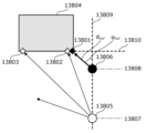
- FIG. 1 is a diagram for explaining a method of encoding or decoding three-dimensional points represented by polar coordinates using inter prediction according to Embodiment 1.
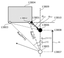
- FIG. 2 is a diagram for explaining a method of encoding or decoding three-dimensional points represented by polar coordinates using inter-prediction according to Embodiment 1.
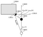
- FIG. 3 is a diagram for explaining a method of encoding or decoding three-dimensional points represented by polar coordinates using inter prediction according to the first embodiment.
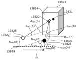
- FIG. 4 is a diagram for explaining a method of encoding or decoding three-dimensional points represented by polar coordinates using inter prediction according to Embodiment 1.
- FIG. 5 is a flowchart illustrating an example of a processing procedure of an inter prediction method according to Embodiment 1.
- FIG. FIG. 6 is a diagram for explaining a first example of switching the derivation method of the predicted value according to the value of the horizontal angle according to the first embodiment.
- FIG. 7 is a diagram showing a formula for deriving the predicted value d pred determined for each of the four directions defined by the horizontal angle ⁇ cur according to the first embodiment.
- FIG. 8 is a diagram for explaining a second example of switching the method of deriving the predicted value according to the value of the horizontal angle according to the first embodiment.
- FIG. 9 is a diagram showing a formula for deriving the predicted value d pred determined for each of eight directions defined by the horizontal angle ⁇ cur according to the first embodiment.
- 10 is a block diagram of a three-dimensional data encoding device according to Embodiment 2.
- FIG. 11 is a block diagram of a three-dimensional data decoding device according to Embodiment 2.
- FIG. 12 is a flowchart of encoding or decoding processing including inter prediction processing according to Embodiment 2.
- FIG. 13 is a diagram for explaining an example of an inter prediction method according to Embodiment 2.
- FIG. 14 is a flowchart of inter prediction processing according to Embodiment 2.
- FIG. 15 is a flowchart of three-dimensional data encoding processing according to Embodiment 2.
- FIG. FIG. 16 is a flowchart of three-dimensional data decoding processing according to the second embodiment.
- a three-dimensional data encoding method corrects position information of one or more first three-dimensional points according to a coordinate system of a target three-dimensional point to be encoded, thereby obtaining a first reference. generating a point group, and converting one of the first reference point group and a second reference point group including the one or more first three-dimensional points before correction to the third point group for the target three-dimensional point; 3 reference point group, determine a prediction point using the third reference point group, and encode the position information of the target three-dimensional point by referring to at least part of the position information of the prediction point do.
- the three-dimensional data encoding method selectively uses the corrected first reference point group and the second reference point group before correction to encode the target points. Therefore, according to the three-dimensional data encoding method, there is a possibility that a prediction point that reduces the prediction error can be determined. Therefore, the three-dimensional data encoding method can improve the encoding efficiency. Also, the three-dimensional data encoding method can reduce the amount of data handled in the encoding process.
- the one or more first cubic The position information of the original point may be matched with the coordinate system of the target three-dimensional point.
- one or more of the one or more included in the first reference point group Location information for the second three-dimensional point may be derived.
- the first information may include at least one of second information regarding movement parallel to a horizontal plane and third information regarding rotation about a vertical axis.
- the position information may include a distance component, a horizontal angle component and an elevation angle component, and the correction may correct at least one of the distance component and the horizontal angle component. That is, in this aspect, the elevation component in polar coordinates is not corrected. Therefore, this aspect is suitable for selectively using the reference point group whose position is corrected in the horizontal direction and the reference point group before correction. For example, this aspect is suitable for 3D point clouds obtained with a sensor that repeatedly moves and stops in the horizontal direction.
- the three-dimensional data encoding method further includes determining whether to perform the correction, encoded position information of the target three-dimensional point, and fourth information indicating whether to perform the correction. may generate a bitstream containing
- the three-dimensional data encoding method can determine a prediction point that reduces the prediction error by switching whether to perform correction or not.
- the second reference point group may be selected as the third reference point group.
- the one or more first three-dimensional points are included in a first processing unit, and when the correction is not performed, the second reference point group and a third point group different from the first processing unit.
- the three-dimensional data encoding method can refer to two processing units without correction when correction is not performed. Therefore, the three-dimensional data encoding method can improve the encoding efficiency.
- the first reference point group may be generated by correcting one or more fourth three-dimensional points that are part of the one or more first three-dimensional points.
- the three-dimensional data encoding method can reduce the amount of processing by limiting the three-dimensional points to be corrected. For example, if the relative positional relationship between the target 3D point and the origin is approximately the same as the relative positional relationship between the predicted point and the origin included in the reference point group, the prediction error is can be suppressed. On the other hand, if the relative positional relationship between the target 3D point and the origin differs from the relative positional relationship between the predicted points included in the reference point group and the origin, the predicted error can be suppressed by using the corrected predicted points. can be done. In this way, by switching whether or not correction should be performed depending on the position of the target three-dimensional point, the prediction error can be reduced.
- the position information includes a distance component, a horizontal angle component, and an elevation angle component
- the fourth three-dimensional point is selected from the one or more first three-dimensional points by a predetermined value.
- a three-dimensional point with a large elevation angle component represents, for example, a building. The building is fixed on the ground. Therefore, when the target 3D point and the predicted point represent a building, the relative positional relationship between the target 3D point and the origin differs from the relative positional relationship between the predicted point and the origin included in the reference point group. In this case, prediction errors can be suppressed by using corrected prediction points. Therefore, in the three-dimensional data encoding method, the objects to be corrected are limited to buildings and the like.
- the fourth three-dimensional point may be a first three-dimensional point whose vertical position is higher than a predetermined position among the one or more first three-dimensional points.
- a three-dimensional data decoding method corrects position information of one or more first three-dimensional points in accordance with a coordinate system of a target three-dimensional point to be decoded to generate a first reference point group. and converting one of the first reference point group and the second reference point group including the one or more first three-dimensional points before correction to a third reference point group for the target three-dimensional point A prediction point is determined using the third reference point group, and the position information of the target three-dimensional point is decoded by referring to at least part of the position information of the prediction point.
- the three-dimensional data decoding method selectively uses the corrected first reference point group and the second reference point group before correction to decode the target point. Therefore, according to the three-dimensional data decoding method, there is a possibility that a prediction point that reduces the prediction error can be determined. Therefore, the three-dimensional data decoding method can suppress the amount of data handled in the decoding process.
- the one or more first cubic The position information of the original point may be matched with the coordinate system of the target three-dimensional point.
- one or more of the one or more included in the first reference point group Location information for the second three-dimensional point may be derived.
- the first information may include at least one of second information regarding movement parallel to a horizontal plane and third information regarding rotation about a vertical axis.
- the position information may include a distance component, a horizontal angle component and an elevation angle component, and the correction may correct at least one of the distance component and the horizontal angle component. That is, in this aspect, the elevation component in polar coordinates is not corrected. Therefore, this aspect is suitable for selectively using the reference point group whose position is corrected in the horizontal direction and the reference point group before correction. For example, this aspect is suitable for 3D point clouds obtained with a sensor that repeatedly moves and stops in the horizontal direction.
- the three-dimensional data decoding method further acquires fourth information indicating whether or not to perform the correction from the bitstream, and determines whether or not to perform the correction based on the fourth information. good too.
- the three-dimensional data decoding method can determine a prediction point that reduces the prediction error by switching whether to perform correction or not.
- the second reference point group may be selected as the third reference point group.
- the one or more first three-dimensional points are included in a first processing unit, and when the correction is not performed, the second reference point group and a third point group different from the first processing unit.
- the three-dimensional data decoding method can refer to two processing units without correction when correction is not performed. Therefore, the three-dimensional data decoding method can improve the encoding efficiency.
- the first reference point group may be generated by correcting one or more fourth three-dimensional points that are part of the one or more first three-dimensional points.
- the three-dimensional data decoding method can reduce the amount of processing by limiting the three-dimensional points to be corrected. For example, if the relative positional relationship between the target 3D point and the origin is approximately the same as the relative positional relationship between the predicted point and the origin included in the reference point group, the prediction error is can be suppressed. On the other hand, if the relative positional relationship between the target 3D point and the origin differs from the relative positional relationship between the predicted points included in the reference point group and the origin, the predicted error can be suppressed by using the corrected predicted points. can be done. In this way, by switching whether or not correction should be performed depending on the position of the target three-dimensional point, the prediction error can be reduced.
- the position information includes a distance component, a horizontal angle component, and an elevation angle component
- the fourth three-dimensional point is selected from the one or more first three-dimensional points by a predetermined value.
- a three-dimensional point with a large elevation angle component represents, for example, a building. The building is fixed on the ground. Therefore, when the target 3D point and the predicted point represent a building, the relative positional relationship between the target 3D point and the origin differs from the relative positional relationship between the predicted point and the origin included in the reference point group. In this case, prediction errors can be suppressed by using corrected prediction points. Therefore, in the three-dimensional data decoding method, the objects to be corrected are limited to buildings and the like.
- the fourth three-dimensional point may be a first three-dimensional point whose vertical position is higher than a predetermined position among the one or more first three-dimensional points.
- a three-dimensional data encoding device includes a processor and a memory, and the processor uses the memory to encode position information of one or more first three-dimensional points. generating a first reference point group by correcting it according to the coordinate system of the target three-dimensional point to be converted, and combining the first reference point group and the one or more first three-dimensional points before correction selecting as a third reference point cloud for the target three-dimensional point a second reference point cloud comprising: determining predicted points using the third reference point cloud; The position information of the target 3D point is encoded with reference to at least part of the position information.
- the three-dimensional data encoding device selectively uses the corrected first reference point group and the second reference point group before correction to encode the target point. Therefore, according to the three-dimensional data encoding device, there is a possibility that a prediction point that reduces the prediction error can be determined. Therefore, the three-dimensional data encoding device can improve encoding efficiency. Also, the three-dimensional data encoding device can reduce the amount of data handled in the encoding process.
- a three-dimensional data decoding device includes a processor and a memory, and the processor uses the memory to determine position information of one or more first three-dimensional points to be decoded.
- a first reference point group is generated by correcting according to the coordinate system of the target three-dimensional point, and the first reference point group and the one or more first three-dimensional points before correction are included in the 2 reference point cloud as a third reference point cloud for the target three-dimensional point, determining a predicted point using the third reference point cloud, and position information of the predicted point to decode the position information of the target three-dimensional point by referring to at least a part of
- the three-dimensional data decoding device selectively uses the corrected first reference point group and the second reference point group before correction to decode the target point. Therefore, according to the three-dimensional data decoding device, there is a possibility that the prediction point that reduces the prediction error can be determined. Therefore, the three-dimensional data decoding method can suppress the amount of data handled in the decoding process.
- Embodiment 1 a three-dimensional data encoding method and a three-dimensional data decoding method for performing inter prediction on a point group including a plurality of three-dimensional points whose position information indicating each position is expressed in a polar coordinate system will be described. . It should be noted that the positional information may be simply referred to as position. A method of determining one or more candidate points used to determine a predicted value for inter prediction will be mainly described below.
- 1 to 3 are diagrams for explaining a method of encoding or decoding three-dimensional points represented by polar coordinates using inter-prediction.
- inter prediction refers to one or more encoded points included in a reference frame that is a frame different from the encoding target frame when encoding the encoding target 3D point included in the encoding target frame. and predictively encode a plurality of 3D points included in the encoding target frame based on one or more 3D points referred to.
- intra prediction means that, when encoding a 3D point to be coded included in the frame to be coded, at least one of the other coded 3D points included in the frame to be coded is predicted. This is a method of predictively encoding a plurality of 3D points included in a frame to be encoded based on one or more 3D points referred to.
- the encoding target frame may also be referred to as a second frame.
- a reference frame may also be referred to as a first frame.
- the point cloud data has one or more frames, and each of the one or more frames has one or more three-dimensional points.
- One or more frames include an encoding target frame and a reference frame.
- each frame may be generated by measuring different positions with a sensor.
- Each frame may be generated by being measured by a plurality of different sensors.
- the plurality of first three-dimensional points are obtained by measuring the distance to the object in each of the plurality of first directions around the first position in the space on the reference plane.
- the first position is a first origin that serves as a reference for position information of a plurality of first three-dimensional points, which are measurement results obtained by sensors placed at the third position.
- the first position may also be referred to as the first reference position.
- the first location may or may not coincide with the third location where the sensor is located.
- Each of the plurality of first three-dimensional points is represented by a first polar coordinate system with the first position as the first origin.
- a plurality of first 3D points are included, for example, in the reference frame.
- the plurality of second three-dimensional points are obtained by measuring the distance to the object in each of the plurality of second directions around the second position in the space on the reference plane.
- the second position is a second origin that serves as a reference for positional information of a plurality of second three-dimensional points that are measurement results measured by the sensor arranged at the fourth position.
- the second position may also be referred to as a second reference position.
- the second location may or may not coincide with the fourth location where the sensor is located.
- Each of the plurality of second three-dimensional points is represented by a second polar coordinate system with a second origin at the second position.
- the sensor emits electromagnetic waves and acquires reflected waves of the electromagnetic waves reflected by the subject, thereby generating measurement results including one or more three-dimensional points.
- the sensor may generate one frame containing measurement results obtained by one measurement. Specifically, the sensor measures the time it takes for an emitted electromagnetic wave to reflect off an object and return to the sensor after being emitted, and uses the measured time and the wavelength of the electromagnetic wave to determine the relationship between the sensor and the sensor. Calculate the distance between points on the surface of surrounding objects.
- the sensor emits electromagnetic waves in a plurality of predetermined radial directions from a reference position of the sensor.
- the sensor is, for example, LiDAR, and the electromagnetic wave is, for example, laser light.
- the positional information indicates the position of the three-dimensional point having the positional information and is represented by polar coordinates.
- the position information includes the distance from the reference point to the 3D point having the position information, and two angles indicating the direction from the reference point to the 3D point having the position information.
- One of the two angles is, for example, an angle (horizontal angle) formed by a reference direction perpendicular to the axis when viewed from an axis perpendicular to the reference plane and the above-mentioned direction, and the other is an angle (horizontal angle) between the reference plane and the above-mentioned direction. It is the angle (elevation angle) formed by the direction.
- the reference plane is a horizontal plane, for example, a plane perpendicular to a predetermined axis of the sensor such as the rotation axis of LiDAR, the ground, a floor, or a plane parallel to these.
- Figures 1 to 3 assume the encoding of point groups generated by acquiring the three-dimensional positions of objects around the sensor centered around the sensor position, such as LiDAR. 1 to 3, for example, the second reference position 13808 of the sensor 13806 when measuring the point cloud of the encoding target frame, the first reference position 13807 of the sensor 13805 when measuring the point cloud of the reference frame, and The positional relationship between a conversion target point 13801 and reference candidate points 13802 and 13803 in inter prediction is shown.
- 1 to 3 show, for example, a sensor such as LiDAR that emits a laser around a predetermined axis (rotational axis) to measure the distance to an object, viewed from the axial direction. It is a plan view of the case.
- An encoding target point 13801 and reference candidate points 13802 and 13803 indicate three-dimensional positions on the same plane (for example, plane) 13810 of the object 13804 .
- An encoding target point 13801 is included in the point group of the encoding target frame.
- the point cloud of the frame to be encoded is indicated by black diamond-shaped points in FIGS.
- Candidate reference points 13802 and 13803 are included in the point cloud of the reference frame and included in a plurality of (eg, n+1) three-dimensional points indicating three-dimensional positions on the surface 13810 .
- the point cloud of the reference frame is indicated by the open diamond-shaped points in FIGS. 1-3.
- the sensor 13805 and the sensor 13806 may be the same sensor or different sensors (that is, separate sensors).
- the sensor 13805 and the sensor 13806 are the same sensor, for example, when one sensor moves from the first reference position 13807 to the second reference position 13808 or from the second reference position 13808 to the first reference position 13807 is.
- the time when the encoding target frame was generated differs from the time when the reference frame was generated.
- the sensor 13805 and the sensor 13806 are different sensors, the time at which the encoding target frame was generated and the time at which the reference frame was generated may be different or the same.
- the three-dimensional data encoding device calculates the predicted value d_pred of the distance d_cur from the second reference position 13808 of the sensor 13806 to the encoding target point 13801 as the second It is determined based on the positional relationship among the reference position 13808, the first reference position 13807 of the sensor 13805 during measurement of the point group of the reference frame, the encoding target point 13801, and the reference candidate points 13802 and 13803. Then, the 3D data encoding device may use the determined prediction value d pred for inter prediction. For example, the 3D data encoding device may determine the predicted value d pred by executing the following procedures 1 to 3. Since the 3D data decoding device determines the predicted value d pred by performing the same processing as the 3D data encoding device, only the 3D data encoding device will be described below.
- the three-dimensional data encoding device projects at least one reference candidate point 13802, 13803 onto the second polar coordinate system of the second reference position 13808, as shown in FIG.
- the horizontal angle ⁇ ref2 (i) of the i-th reference candidate point viewed from position 13808 is derived.
- ⁇ ref1 (i), d ref1 (i), and m are respectively the horizontal angle at the first reference position 13807 shown in FIG. 2, the distance from the first reference position 13807 to the i-th reference candidate point, and the distance between the first reference position 13807 and the second reference position 13808 (inter-sensor distance or movement distance).
- the horizontal angle is the angle of the direction in which the i-th reference candidate point exists with respect to the first reference position 13807, with reference to the reference direction 13809, which is the direction connecting the first reference position 13807 and the second reference position 13808.
- n is a natural number that can take i and k. i is any natural number.
- ⁇ ref2 (i) arctan( d ref1 (i) sin( ⁇ ref1 (i)) / (d ref1 (i) cos( ⁇ ref1 (i)) - m) ) (Formula Z1)
- the three-dimensional data encoding device selects from at least one horizontal angle ⁇ ref2 (i) corresponding to the i-th reference candidate point, the horizontal angle pointing from the second reference position 13808 to the encoding target point 13801.
- a horizontal angle ⁇ ref2 (k) near ⁇ cur is selected, and the k-th reference candidate point 13802 indicated by the horizontal angle ⁇ ref2 (k) is used for inter prediction (inter reference point ) 13811.
- k is a natural number indicating a horizontal angle near the horizontal angle ⁇ cur pointing from the second reference position 13808 to the encoding target point 13801 among n horizontal angles ⁇ ref2 . That is, the k-th reference candidate point is a reference point used for calculating the predicted value among the n reference candidate points, and is an example of the encoded first three-dimensional point.
- the 3D data encoding device derives the distance d ref2 (k) from the second reference position 13808 to the inter reference point 13811, and determines the distance d ref2 (k) as the predicted value d pred .
- the point group of the encoding target frame and the point group of the reference frame are expressed in polar coordinates of a coordinate system having different reference positions. Therefore, when the encoding target point 13801 is predictively encoded using the reference candidate points 13802 and 13803 of the reference frame different from the encoding target frame, the coordinate system of the reference candidate points 13802 and 13803 of the reference frame is set to the reference frame. It is necessary to perform a coordinate system transformation that transforms from a first coordinate system in which the point cloud of the coded frame is represented to a second coordinate system in which the point cloud of the encoded frame is represented.
- the three-dimensional data encoding device specifies the encoded first three-dimensional point whose position is represented by the first polar coordinates by executing procedures 1 to 3.
- FIG. The first 3D point is the reference point used for prediction.
- the three-dimensional data encoding device calculates the predicted value of the distance d cur from the second reference position 13808 of the uncoded second three-dimensional point whose position is expressed in the second polar coordinate system.
- the distance d cur is an example of the second distance.
- the distance m is an example of the distance between the first position and the second position.
- the horizontal angle ⁇ ref1 (k) is an example of the first angle and indicates the angle formed by the first line and the second line.
- the distance d ref1 (k) is an example of the first distance.
- the three-dimensional data encoding device uses the distance m, horizontal angle ⁇ ref1 (k), and Using the distance d ref1 (k), (iv) the horizontal angle ⁇ ref2 (k) between the first line and the third line connecting the second reference position 13808 and the reference point 13811, and (v) the second A distance d cur of the reference point 13811 in the polar coordinate system from the second reference position 13808 is calculated.
- the horizontal angle ⁇ ref2 (k) is an example of the second angle.
- the distance A horizontal angle ⁇ ref2 (k) is calculated using d ref1 (k) and the horizontal angle ⁇ ref1 (k) as the first angle.
- the horizontal angle ⁇ ref1 (k) is an example of a first horizontal angle, and is a horizontal angle component of the polar coordinate components representing the position of the reference point 13811 .
- the position of reference point 13811 is expressed in the first polar coordinate system.
- the device may calculate the difference between the horizontal angle component of the polar coordinate components representing the position of the reference point 13811 and the angle formed by the first line with respect to the reference line as the first angle.
- the three-dimensional data encoding device determines the first three-dimensional point based on the other second three-dimensional point whose position is expressed in the second polar coordinate system and which has already been encoded. may be specified.
- the three-dimensional data encoding device can highly accurately predict the distance d cur from the second reference position 13808 of the encoding target frame to the encoding target point 13801, and the efficiency of inter prediction encoding can be improved. could be improved.
- the movement distance m is the result of measurement using sensors such as GPS (Global Positioning System) and odometer, and using self-position estimation technology using SfM (Structure from Motion), SLAM (Simultaneous Localization and Mapping), etc. may be generated based on the results derived by Further, these results may be included in header information in predetermined data units such as frames and slices, and information on the head node of these data units. Thereby, these results may be notified from the 3D data encoding device to the 3D data decoding device.
- GPS Global Positioning System
- SfM Structure from Motion
- SLAM Simultaneous Localization and Mapping
- d ref2 (k) may be derived from equation Z3.
- the 3D data encoding apparatus may determine inter reference points by projecting all reference candidate points of the reference frame onto the second polar coordinate system of the second reference position 13808 of the encoding target frame.
- the 3D data encoding apparatus may perform the coordinate system transformation described above on all reference candidate points in the reference frame, and determine inter reference points based on all post-transformation candidate points.
- the 3D data encoding device may generate a horizontal angle ⁇ cur of the encoding target point 13801, the distance m between the first reference position 13807 and the second reference position 13808, and the like, and calculate the horizontal angle of the reference frame with respect to the sensor 13805.
- the reference candidate points may be limited to points included in a partial range of .
- the process of determining the inter reference point is not performed.
- the reference candidate points are limited to those located in an area ahead of the first reference position in the direction connecting the first reference position and the second reference position.
- the three-dimensional data encoding device limits the reference candidate points to be subjected to coordinate system conversion to a part of all the reference candidate points based on the horizontal angle ⁇ cur and the distance m. It is possible to suppress the amount of processing related to
- arithmetic processing such as trigonometric functions and division in each of the above procedures may be simplified by using a table consisting of a finite number of elements.
- the simplification makes it possible to improve the efficiency of inter prediction coding while suppressing the amount of processing.
- the angle formed by the reference direction 13809 in FIGS. 1 to 3 and the same plane (eg plane) 13810 of the object 13804 is not limited. That is, the direction of the first line connecting the first reference position 13807 and the second reference position 13808 can take any angle with respect to the horizontal axis included in the same plane (eg plane) 13810 of the object 13804 . Even in that case, the predicted value can be calculated using the above method.
- FIG. 4 assumes encoding of a point group generated by acquiring the three-dimensional positions of objects around the sensor, centering on the sensor position, such as LiDAR.
- a predicted value d pred of the distance d cur from the sensor 13826 of the encoding target frame to the encoding target point 13821 may be determined by also considering ⁇ cur .
- the second reference position 13828 of the sensor 13826 of the encoding target frame, the first reference position 13827 of the sensor 13826 of the reference frame, the encoding target point 13821, and the reference candidate point 13822 in inter prediction Positional relationships are indicated.
- An encoding target point 13821 and a reference candidate point 13822 indicate three-dimensional positions on the same plane (for example, plane) 13824 of the object 13823 .
- the encoding target point 13821 is included in the point group of the encoding target frame.
- the point cloud of the frame to be encoded is indicated by black rhombic points in FIG.
- the reference candidate point 13822 is a three-dimensional point that is included in the point cloud of the reference frame and indicates the three-dimensional position of the object 13823 on the surface 13824 .
- a reference frame includes one or more 3D points, and may include multiple (eg, n) 3D points.
- the point cloud of the reference frame is indicated by the open diamond-shaped points in FIG.
- the sensors 13825 and 13826 may be the same sensor or different sensors (that is, different sensors). When the sensor 13825 and the sensor 13826 are the same sensor, for example, when one sensor moves from the first reference position 13827 to the second reference position 13828 or from the second reference position 13828 to the first reference position 13827 is.
- the time when the encoding target frame was generated differs from the time when the reference frame was generated.
- the sensor 13825 and the sensor 13826 are different sensors, the time at which the encoding target frame was generated and the time at which the reference frame was generated may be different or the same.
- the 3D data encoding device may determine the predicted value d pred by performing the following procedures 11 to 13.
- the three-dimensional data encoding device projects at least one reference candidate point 13822 onto the second polar coordinate system of the second reference position 13828, and calculates i
- the horizontal angle ⁇ ref2 (i) and the elevation angle ⁇ ref2 (i) of the th reference candidate point are derived.
- ⁇ ref2 (i), ⁇ ref2 (i), d ref1 (i), and m are respectively the horizontal angle and elevation angle at the first reference position 13827 shown in FIG.
- the distance to the reference candidate point and the distance between the first reference position 13827 and the second reference position 13828 are shown.
- the horizontal angle is the angle of the direction in which the i-th reference candidate point exists with respect to the first reference position 13827 with reference to the reference direction 13829 of the first reference position 13827 and the second reference position 13828 .
- the elevation angle is the angle of the direction in which the i-th reference candidate point exists with respect to the first reference position 13827 with respect to the horizontal plane.
- n is a natural number that can take i and k. i is any natural number.
- h ref1 (i) indicates the height of sensor 13825 from the reference plane
- h ref2 (i) indicates the height of sensor 13826 from the reference plane.
- the three-dimensional data encoding device encodes from the second reference position 13828 from among combinations of at least one horizontal angle ⁇ ref2 (i) and elevation angle ⁇ ref2 (i) corresponding to the reference candidate point 13822.
- the k-th reference candidate point 13822 indicated by the combination of k) is selected as a reference point (inter reference point) used for inter prediction.
- k is the horizontal angle ⁇ ref2 ( k ) and the elevation angle ⁇ ref2 (k). That is, the k-th reference candidate point is a reference point used for calculating the predicted value among the n reference candidate points, and is an example of the encoded first three-dimensional point.
- the three-dimensional data encoding device derives the distance d ref2 (k) from the second reference position 13828 to the reference candidate point 13822 selected as the inter reference point, and predicts the distance d ref2 (k). Determine as the value d pred .
- the three-dimensional data encoding device can accurately predict the distance d cur from the sensor 13826 of the encoding target frame to the encoding target point 13821, and the efficiency of inter prediction encoding can be improved. have a nature.
- d ref2 (k) may be derived from equation Z7 in procedure 13 above.
- the three-dimensional data encoding device may determine the inter reference point by projecting all reference candidate points of the reference frame onto the second polar coordinate system of the second reference position 13828 of the sensor 13826 of the encoding target frame. good. That is, the three-dimensional data encoding device may project all reference candidate points of the reference frame onto the second polar coordinate system of the second reference position, and determine inter reference points based on all post-transformation candidate points. .
- the three-dimensional data encoding device can detect the sensor 13825 of the reference frame based on the horizontal angle ⁇ cur or the elevation angle ⁇ cur of the encoding target point 13821, the distance m between the first reference position 13827 and the second reference position 13828, and the like.
- the reference candidate points may be limited to points included in a partial range of the horizontal angle and elevation angle with respect to . As a result, it is possible to reduce the amount of processing for determining inter reference points.
- the three-dimensional data encoding device limits reference candidate points to be subjected to coordinate system transformation to a part of all reference candidate points based on the horizontal angle ⁇ cur , elevation angle ⁇ cur , distance m, and the like. , the amount of processing involved in coordinate system conversion can be suppressed.
- arithmetic processing such as trigonometric functions and division in each of the above procedures may be simplified using a table having a finite number of elements.
- ⁇ ref2 (i) may be obtained from equation Z8 assuming that (h ref1 ( i ) ⁇ h ref2 (i))/d ref1 (i) is sufficiently small.
- ⁇ ref2 (i) arctan( tan( ⁇ ref1 (i)) sin( ⁇ ref2 (i))/sin( ⁇ ref1 (i)) ) (Formula Z8)
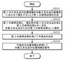
- FIG. 5 is a flowchart showing an example of the processing procedure of the inter prediction method.
- the 3D data encoding apparatus determines intra prediction points (d intra , ⁇ intra , ⁇ intra ) in the encoding target frame as reference points for inter prediction (S13801).
- the intra prediction information may be notified, and the prediction value obtained by the prediction method determined to be an appropriate intra prediction method may be used. may be omitted.
- the intra prediction point determined as the reference point for inter prediction may be a three-dimensional point used to calculate the predicted value of the three-dimensional point to be encoded in the second polar coordinate system.
- the 3D data encoding device projects the intra prediction points (d intra , ⁇ intra , ⁇ intra ) onto the first polar coordinate system of the reference frame, and the angle ( ⁇ sref , ⁇ sref ) are determined (S13802). Note that the angles ( ⁇ sref , ⁇ sref ) may be determined by Equations Z9 and Z10.
- the three-dimensional data encoding device converts one or more three-dimensional points having angles ( ⁇ ref1 (i), ⁇ ref1 (i)) near angles ( ⁇ sref , ⁇ sref ) in the reference frame to A reference candidate point is selected by a predetermined method (S13803).
- the three-dimensional data encoding device selects one or more laser scanning lines having an angle close to the elevation angle ⁇ sref , and selects laser scanning lines close to the elevation angle ⁇ sref in order of the horizontal angle ⁇ sref for each laser scanning line.
- One or more three-dimensional points may be selected, and the order of selection may be set as the index of the reference candidate point.
- the three-dimensional data encoding device projects the reference candidate points (d ref1 (i), ⁇ ref1 (i), ⁇ ref1 (i)) onto the second polar coordinate system at the second reference position of the encoding target frame. Then, the angle ( ⁇ ref2 (i), ⁇ ref2 (i)) in the encoding target frame is derived (S13804). Note that the angle ( ⁇ ref2 (i), ⁇ ref2 (i)) may be derived from equations Z11 and Z12.
- the three-dimensional data encoding device selects inter reference points ( ⁇ ref2 (k), ⁇ ref2 (k)) from angles ( ⁇ ref2 (i), ⁇ ref2 (i)) by a predetermined method.
- Select S13805
- the 3D data encoding apparatus may select a reference candidate point having an angle closest to the angle ( ⁇ cur , ⁇ cur ) as an inter reference point.
- the inter reference point is identified based on the angular component of the polar coordinate components representing the positions of other second three-dimensional points included in the encoding target frame.
- the inter-reference point is represented by the first polar coordinate system, and among the plurality of first three-dimensional points including other encoded first three-dimensional points, the inter reference point is the first polar coordinate system to the second
- the angle component of the plurality of projected first three-dimensional points after being projected onto the polar coordinate system is closest to the angle component of the point to be encoded.
- the three-dimensional data encoding device may notify the three-dimensional data decoding device of the index k of the inter reference point selected by a predetermined method.
- the 3D data encoding device derives the distance d ref2 (k) from the first reference position of the encoding target frame to the inter reference point, and determines the distance d ref2 (k) as the predicted value d pred . (S13806). Note that the distance d ref2 (k) may be derived by either formula Z13 or Z14.
- d ref2 (k) d ref1 (k) sin( ⁇ ref1 (k))/sin( ⁇ ref2 (k)) (equation Z13)
- d ref2 (k) (d ref1 (k)cos( ⁇ ref1 (k)) ⁇ m)/cos( ⁇ ref2 (k)) (equation Z14)
- the three-dimensional data encoding apparatus projects the intra prediction point of the encoding target frame onto the first polar coordinate system at the first reference position of the reference frame, and generates one or more inter reference point candidates based on the angle. may be selected.
- the number of reference candidate points used for inter prediction can be reduced, and the processing amount of inter prediction can be reduced.
- arithmetic processing such as trigonometric functions and division in the above procedure may be simplified using a table having a finite number of elements.
- inter prediction and intra prediction may be switched for each node or slice, or intra prediction or other inter prediction may be switched for each node or slice.
- FIG. 6 is a diagram for explaining a first example of switching the method of deriving the predicted value according to the value of the horizontal angle.
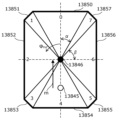
- FIG. 7 is a diagram showing a formula for deriving the predicted value d pred determined for each of the four directions defined by the horizontal angle ⁇ cur . Index in FIG. 7 indicates index values 0 to 3 corresponding to the virtual planes 13840 to 13843 set in FIG.
- a virtual plane perpendicular to a horizontal plane is set as an object in four directions, front, back, left , and right.
- the predicted value d pred is derived by the formula shown. That is, the 3D data encoding device acquires the horizontal angle ⁇ cur of the encoding target point and derives the predicted value d pred based on the equation corresponding to the horizontal angle ⁇ cur shown in FIG.
- ⁇ may be changed by being notified from the 3D data encoding device to the 3D data decoding device. Further, it is sufficient that the range to include the boundary line of each range is consistent between the encoding process and the decoding process, and does not necessarily have to be as shown in FIG. 7 .
- the three-dimensional data encoding apparatus includes a first determination method of a predicted value in predictive coding for a plurality of three-dimensional points on the first plane, and a predictive coding method for a plurality of three-dimensional points on the second plane. may be different from the second determination method of the predicted value in .
- predictive encoding is inter-prediction in which encoding target points of an encoding target frame are predictively encoded using reference candidate points of a reference frame different from the encoding target frame.
- the first plane is a plane facing the first reference position and the second reference position in the third direction, and is a plane perpendicular to the reference plane.
- the second plane is a plane facing the first reference position and the second reference position in the fourth direction, and is a plane perpendicular to the reference plane.
- the third direction and the fourth direction are directions different from each other.
- Some of the plurality of 3D points on the first plane are included in the plurality of first 3D points included in the reference frame.
- Some of the plurality of 3D points on the first plane are included in the plurality of second 3D points included in the encoding target frame.
- Some of the plurality of 3D points on the second plane are included in the plurality of first 3D points included in the reference frame.
- Another part of the plurality of 3D points on the second plane is included in the plurality of second 3D points included in the second frame.
- the distance d cur from the second reference position of the encoding target frame to the encoding target point is obtained from the point group obtained by the sensor 13845 of the reference frame at the first reference position which is the distance m from the second reference position. Based on this, prediction can be performed with higher precision than the inter prediction method described with reference to FIGS. 2 to 5, and the efficiency of inter prediction coding can be further improved.
- arithmetic processing such as trigonometric functions and division in FIG. 7 may be simplified by using a table consisting of a finite number of elements.
- the simplification makes it possible to improve the efficiency of inter prediction coding while suppressing the amount of processing.
- FIG. 8 is a diagram for explaining a second example in which the prediction value derivation method is switched according to the value of the horizontal angle.
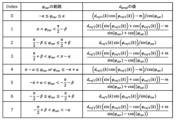
- FIG. 9 is a diagram showing a formula for deriving the predicted value d pred determined for each of the eight directions defined by the horizontal angle ⁇ cur . Index in FIG. 9 indicates index values 0 to 7 corresponding to the virtual planes 13840 to 13843 set in FIG.
- a virtual plane perpendicular to a horizontal plane (reference plane) as an object is set in eight directions: four directions, front, back, left, and right, and four oblique directions between the four directions.
- a predicted value d pred is derived from the formula shown in FIG. 9 for each of the eight ranges divided by cur . That is, the 3D data encoding device acquires the horizontal angle ⁇ cur of the encoding target point and derives the predicted value d pred based on the equation corresponding to the horizontal angle ⁇ cur shown in FIG.
- ⁇ and ⁇ may be included in header information in predetermined data units such as sequences, frames, and slices. Accordingly, ⁇ and ⁇ may be notified from the 3D data encoding device to the 3D data decoding device and changed. In addition, it is sufficient that the range to include the boundary line of each range matches between the encoding process and the decoding process, and does not necessarily have to be as shown in FIG. 9 .
- the distance d cur from the second reference position of the encoding target frame to the encoding target point is calculated based on the point group obtained by the sensor 13845 of the reference frame at the first reference position which is the distance m from the sensor 13846.
- prediction can be performed with higher accuracy than the inter prediction methods described with reference to FIGS. 2 to 7, and the efficiency of inter prediction coding can be further improved.
- arithmetic processing such as trigonometric functions and division in FIG. 9 may be simplified by using a table consisting of a finite number of elements.
- the simplification may improve the efficiency of inter-prediction coding while suppressing the amount of processing.
- Three-dimensional data is, for example, point cloud data.
- a point cloud is a collection of a plurality of three-dimensional points and indicates the three-dimensional shape of an object.
- the point cloud data includes position information and attribute information of a plurality of 3D points.
- the position information indicates the three-dimensional position of each three-dimensional point.
- position information may also be called geometry information.
- positional information is represented by a rectangular coordinate system or a polar coordinate system.
- Attribute information indicates, for example, color, reflectance, or normal vector.
- One three-dimensional point may have one piece of attribute information or may have a plurality of pieces of attribute information.
- the three-dimensional data is not limited to point cloud data, and may be other three-dimensional data such as mesh data.
- Mesh data also referred to as three-dimensional mesh data
- CG Computer Graphics
- mesh data includes point cloud information (eg, vertex information). Therefore, the same method as the method corresponding to the point cloud data can be applied to this point cloud information.
- FIG. 10 is a block diagram showing the configuration of a three-dimensional data encoding device according to this embodiment.
- the three-dimensional data encoding device 100 supports inter-predictive encoding in which a point group to be encoded is encoded while referring to an encoded point group.
- This 3D data encoding apparatus 100 includes an encoding section 101, a motion compensation section 102, a first buffer 103, a second buffer 104, a switching section 105, and an inter prediction section .
- FIG. 10 only shows a configuration related to inter prediction encoding of position information
- the 3D data encoding device 100 includes other processing units related to encoding of position information (for example, an intra prediction unit, etc.). may be provided, or an attribute information encoding unit or the like for encoding attribute information may be provided.
- the encoding unit 101 generates a bitstream by encoding the target point group, which is the input point group to be encoded. Specifically, the encoding unit 101 extracts a prediction tree (predtree), which is a unit of encoding processing, from the target point group, and encodes each point included in the prediction tree while referring to inter prediction points. become The encoding unit 101 also outputs decoded points obtained by reproducing points obtained by decoding the bitstream. This decoding point is used for inter-prediction of subsequent points of interest (eg, points of interest of subsequent frames or slices).
- predtree a prediction tree
- This decoding point is used for inter-prediction of subsequent points of interest (eg, points of interest of subsequent frames or slices).
- the position information of the target point group and the position information of the decoding points are represented by, for example, polar coordinates.
- the position information of the target point group is represented by orthogonal coordinates, and the encoding unit 101 may convert the position information of the orthogonal coordinates into position information of polar coordinates, and encode the converted position information of polar coordinates.
- the motion compensation unit 102 performs motion compensation on the decoding points, and stores the motion-compensated reference point group (first reference point group) in the first buffer 103 .
- the motion compensation unit 102 performs motion compensation by projecting the position information of the decoding points onto the polar coordinates of the target point group using the inter prediction method in the polar coordinate system described in the first embodiment.
- motion compensation is correcting the position information of the decoding point according to the coordinate system of the target three-dimensional point to be encoded.
- motion compensation includes a process of aligning the origin of the coordinate system of the decoding point with the origin of the coordinate system of the target three-dimensional point, and moving each axis of the coordinate system of the decoding point to each of the coordinate systems of the target three-dimensional point. At least one of the alignment operations may be included.
- Motion compensation may also include coordinate calculations using translation vectors and rotation matrices.
- the decoded points (second reference point group without motion compensation) are stored in the second buffer 104 .
- the switching unit 105 switches one of the first reference point group stored in the first buffer 103 and the second reference point group stored in the second buffer 104 to inter reference points (third reference point group). , and outputs the inter reference point to inter prediction section 106 .
- the inter prediction unit 106 refers to at least one inter reference point stored in the first buffer 103 or the second buffer 104 to determine an inter prediction point.
- the inter prediction unit 106 refers to one or more inter reference points whose positions are the same as or close to the target point among a plurality of inter reference points included in a reference frame different from the target frame including the target point group.
- the inter reference point whose position is the same as or close to the target point is, for example, a point whose elevation angle index and horizontal angle index are the same as or close to the target point (for example, the index value is 1 larger or smaller).
- one 3D point in the reference point group may be selected as a prediction point, or a prediction point may be selected from a plurality of 3D points in the reference point group. may be calculated. For example, the average position of a plurality of 3D points may be calculated as the predicted point position.
- FIG. 11 is a block diagram showing the configuration of the three-dimensional data decoding device according to this embodiment.
- the three-dimensional data decoding device 200 supports inter-prediction decoding in which a point group to be decoded is decoded while referring to a decoded point group.
- This 3D data decoding device 200 comprises a decoding section 201 , a motion compensation section 202 , a first buffer 203 , a second buffer 204 , a switching section 205 and an inter prediction section 206 .
- 3D data decoding device 200 includes other processing units related to decoding of positional information (for example, an intra-prediction unit, etc.).
- an attribute information decoding unit or the like for decoding attribute information may be provided.
- the decoding unit 201 generates a decoded point group by decoding the input bitstream. Specifically, decoding section 201 decodes each point in the prediction tree while referring to the inter prediction point, and outputs the obtained decoding point.
- the motion compensation unit 202, the first buffer 203, the second buffer 204, the switching unit 205, and the inter-prediction unit 206 each operate in the motion compensation unit included in the three-dimensional data encoding apparatus 100 shown in FIG.
- the operations of the section 102, the first buffer 103, the second buffer 104, the switching section 105, and the inter prediction section 106 are the same.
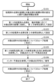
- FIG. 12 is a flowchart showing an example of a processing procedure for encoding or decoding a frame to which inter prediction processing is applied in the 3D data encoding device 100 and the 3D data decoding device 200 shown in FIGS. 10 and 11. .
- the processing shown in FIG. 12 may be repeatedly performed for each frame, or may be repeatedly performed for each processing unit (for example, slice) obtained by dividing a frame.
- the three-dimensional data encoding device 100 and the three-dimensional data decoding device 200 compare the coordinates of the processed point group that has been encoded or decoded and the coordinates of the target point group to be encoded or decoded. Acquire motion information about the displacement between (S101).
- the three-dimensional data encoding device 100 uses an alignment technique such as the ICP (Iterative Closest Point) algorithm to rotate and/or parallelize the coordinates of the processed point group and the target point group. Displacement such as movement is detected, and motion information is determined based on the detected displacement.
- the 3D data encoding apparatus 100 stores motion information in upper syntax (SPS, GPS, slice header, etc.) of the bitstream.
- SPS Sequence Parameter Set
- GPS Global System for Mobile Communications
- the motion information includes, for example, at least one of information about movement parallel to the horizontal plane and information about rotation about the vertical axis.
- the motion information includes, for example, a 3 ⁇ 1 translation matrix.
- the motion information includes the absolute value (
- the motion information includes, for example, a 3x3 rotation matrix.
- the motion information indicates the rotation angle (angle ⁇ described later) of the coordinate axis on the horizontal plane and the rotation around the vertical axis.
- the 3D data decoding device 200 acquires motion information from the bitstream, and performs displacement such as rotation and/or translation between the coordinates of the processed point group and the coordinates of the target point group based on the acquired motion information. set.
- the 3D data encoding device 100 and the 3D data decoding device 200 project at least part of the first processed point group onto the coordinates of the target point group according to the motion information, and the obtained points A cloud is set as a first reference point cloud (S102).
- the inter-prediction method in the polar coordinate system described with reference to FIGS. 1 to 9 in Embodiment 1 may be used.
- the first processed point group is a processed point group included in one frame or one slice.
- the first processed point cloud may be a processed point cloud included in multiple frames or multiple slices.
- the above projection may be performed on all of the distance component, horizontal angle component, and elevation angle component included in the position information, or may be performed on some of them. For example, only the distance component and the horizontal angle component are changed to the values projected from the first processed point cloud to the coordinates of the target point cloud, and the elevation angle component is not changed as the value of the first processed point cloud. good too. Thereby, the amount of processing can be reduced.
- step S103 the 3D data encoding device 100 and the 3D data decoding device 200 directly convert the coordinate information of the second processed point group to the coordinate information of the target point group for at least part of the second processed point group. is set as a second reference point group (S103). Note that step S103 may be performed before step S101 or S102.
- the first processed point group and the second processed point group may be included in the same processing unit (same frame, same slice, etc.) or may be included in different processing units.
- the first processed point cloud and the second processed point cloud may be the corrected (post-projected) point cloud and the uncorrected point cloud of the point cloud included in the same processing unit.
- the point group of this processing unit is the point group whose time is closest to the target point group.
- the second processed point cloud is the point cloud whose time is closest to the target point cloud
- the first processed point cloud is another point cloud whose time is different from the second processed point cloud.
- the three-dimensional data encoding apparatus 100 determines which time point group to use for each of the first processed point group and the second processed point group, and information indicating the determined content, It may be stored in a bitstream higher level syntax (SPS, GPS, slice header, etc.).
- the information includes the time distance between the target point cloud and the point cloud used as the first processed point cloud, and the time distance between the target point cloud and the point cloud used as the second processed point cloud. This is the information shown. Note that when a point cloud common to the first processed point cloud and the second processed point cloud is used, the information may indicate the common point cloud.
- the information may be set for each processing unit (for example, slice or frame).
- the 3D data encoding device 100 can select a processed point group that is suitable for characteristics such as time change of the target point group, which may improve the encoding efficiency.
- the 3D data encoding device 100 and the 3D data decoding device 200 determine an inter-prediction point group for each point, and refer to the inter-prediction points to encode or decode the target point (S104 to S107). .
- the 3D data encoding device 100 and the 3D data decoding device 200 start loop processing for each target point included in the target point group (S104). That is, one of the plurality of points included in the target point group is selected as the target point to be processed.
- the 3D data encoding device 100 and the 3D data decoding device 200 refer to at least part of the reference point group including the first reference point group and the second reference point group to correspond to the target point.
- Inter prediction points to be used are determined (S105).
- the 3D data encoding device 100 and the 3D data decoding device 200 select one of a plurality of inter-reference points included in a reference frame different from the target frame containing the target point group, the position of which is the same as or close to the target point. See the inter-reference points above.
- the inter reference point whose position is the same as or close to the target point is, for example, a point whose elevation angle index and horizontal angle index are the same as or close to the target point (for example, the index value is 1 larger or smaller).
- the three-dimensional data encoding device 100 uses the code amount (residual error) when using inter prediction points determined using the first processed point group, and the second processed point group The amount of code (residual error) when the determined inter prediction point is used is compared, and the one with the smaller amount of code is determined to be selected (referenced). Note that the 3D data encoding apparatus 100 may refer to the first processed point group and the second processed point group to determine the inter prediction point with the smallest code amount.
- whether to use the first processed point group or the second processed point group may be determined according to the characteristics of the target point or the target point group.
- the 3D data encoding device 100 stores information indicating whether to use the first processed point group or the second processed point group, or information indicating inter prediction points in the bitstream, The 3D data decoding device 200 may refer to this information to determine whether to use the first processed point group or the second processed point group, or to determine inter-prediction points.
- the 3D data encoding device 100 encodes the target point with reference to this inter prediction point (S106). Specifically, the 3D data encoding apparatus 100 calculates a residual (difference) between the position information of the target point and the position information of the inter prediction point. The three-dimensional data encoding device 100 generates encoded position information by performing quantization and entropy encoding on the obtained residual. Note that the residual of some of the components of the position information (for example, the distance, the elevation angle, and the horizontal angle) may be calculated, and the original values of the other components may be quantized and entropy-encoded as they are. . Also, the 3D data encoding device 100 generates a bitstream including encoded position information.
- the target point is decoded with reference to this inter prediction point. Specifically, the 3D data decoding device 200 acquires encoded position information of the target point from the bitstream. The 3D data decoding device 200 generates a residual of the target point by performing entropy decoding and inverse quantization on the encoded position information of the target point. The 3D data decoding device 200 generates the position information of the target point by adding the residual of the target point and the position information of the inter prediction point.
- the 3D data encoding device 100 and the 3D data decoding device 200 end loop processing for the target point (S107). That is, steps S105 and S106 are performed for each of the plurality of points included in the target point group.
- the 3D data encoding device 100 and the 3D data decoding device 200 do not always have to refer to inter prediction points to encode or decode target points.
- the 3D data encoding apparatus 100 may store switching information indicating whether to refer to inter prediction points for each node or slice in a bitstream.
- the 3D data decoding device 200 can switch whether to refer to inter prediction points based on the information.
- step S105 may be omitted if the inter prediction point is not referred to. In this way, by making it possible to switch whether to refer to inter prediction points or not, the 3D data encoding device 100 can select an encoding method suitable for characteristics such as time change of the target point cloud. Coding efficiency may be improved.
- FIG. 13 is a diagram for explaining an example of an inter prediction method when performing encoding or decoding using polar coordinates.
- the motion compensation unit 102 shown in FIG. 10 and the motion compensation unit 202 shown in FIG. 11 or in step S102 shown in FIG. Predictive methods may be used. That is, FIG. 13 shows an example of motion compensation.
- the motion vector mv is the displacement on the horizontal plane from the polar coordinate origin of the target frame to be encoded or decoded (frame to be processed) to the polar coordinate origin of the reference frame.
- the angle ⁇ (alpha) is the angle formed by the motion vector mv with respect to the reference direction of the horizontal angle of the target frame.
- the angle ⁇ (beta) is the angle between the reference direction of the horizontal angle of the target frame and the reference direction of the horizontal angle of the reference frame.
- the 3D data encoding device 100 and the 3D data decoding device 200 predict the horizontal angle in the polar coordinates of the target frame.
- the value ⁇ ref2 (n) and the predicted distance value d ref2 (n) may be determined using Equations 1 and 2 below.
- is the magnitude of the motion vector mv.
- ⁇ ref2 (n) arctan(d ref1 (n) sin( ⁇ ref1 (n) ⁇ + ⁇ )/(d ref1 (n) cos( ⁇ ref1 (n) ⁇ + ⁇ )+
- d ref2 (n) d ref1 (n) sin( ⁇ ref1 (n) ⁇ + ⁇ )/sin( ⁇ ref2 (n) ⁇ ) (equation 2)
- the 3D data encoding device 100 and the 3D data decoding device 200 may determine d ref2 (n) using the following (Formula 3) instead of (Formula 2). Note that, when the denominator of division in one of (Equation 2) and (Equation 3) is 0 (zero), three-dimensional data encoding device 100 and three-dimensional data decoding device 200 use the other equation to obtain d ref2 (n) may be determined.
- d ref2 (n) (d ref1 (n)cos( ⁇ ref1 (n) ⁇ + ⁇ )+
- the three-dimensional data encoding device 100 and the three-dimensional data decoding device 200 can highly accurately predict the distance from the polar coordinate origin of the target frame to the target point. This may improve the efficiency of inter prediction coding.
- the predicted value ⁇ ref2 (n) of the elevation angle in the polar coordinates of the target frame may be determined using (Equation Z5) shown in the first embodiment. This may further improve the efficiency of inter prediction encoding.
- the elevation angle ⁇ ref1 (n) in the polar coordinates of the reference frame or its index information may be used as it is as the elevation angle prediction value ⁇ ref2 (n) or its index information. As a result, there is a possibility that the efficiency of inter prediction coding can be improved while suppressing the amount of processing.
- ⁇ ref2 (n) atan2(d ref1 (n) sin( ⁇ ref1 (n) ⁇ + ⁇ ), d ref1 (n) cos( ⁇ ref1 (n) ⁇ + ⁇ )+
- Atan2(0,0) is indefinite
- the angle ⁇ formed by the reference direction of the horizontal angle of the reference frame with respect to the reference direction of the horizontal angle of the motion vector mv and the target frame is (1) measured using a sensor such as a GPS (Global Positioning System) or an odometer, (2) Using at least one of self-position estimation technology using SfM (Structure from Motion) or SLAM (Simultaneous Localization and Mapping), and (3) Alignment technology such as ICP (Iterative Closest Point) algorithm It may be determined based on the derived result.
- a sensor such as a GPS (Global Positioning System) or an odometer
- SfM Structure from Motion
- SLAM Simultaneous Localization and Mapping
- Alignment technology such as ICP (Iterative Closest Point) algorithm It may be determined based on the derived result.
- the 3D data encoding apparatus 100 uses, as motion information, a motion vector mv and an angle ⁇ formed by the reference direction of the horizontal angle of the reference frame with respect to the reference direction of the horizontal angle of the target frame, or information about these values. It may be stored in the header information in units such as slices. Instead of the motion vector mv, the 3D data encoding apparatus 100 stores the magnitude
- FIG. 14 is a flowchart of inter prediction processing. Further, FIG. 14 shows an example of the procedure for deriving the predicted value ⁇ ref2 (n) of the horizontal angle and the predicted value d ref2 (n) of the distance in the polar coordinates of the target frame in the inter prediction method described using FIG. is. Note that the horizontal angle in this example takes a value within the range of - ⁇ to ⁇ . For example, in steps S121 and S129 shown in FIG. 14, 2 ⁇ is added to the result if the result is less than - ⁇ , and 2 ⁇ is subtracted from the result if the result is greater than ⁇ .
- the operation of the 3D data encoding device 100 will be described below, the operation of the 3D data decoding device 200 is the same.
- the three-dimensional data encoding apparatus 100 first sets ⁇ ′ ref1 (n) to ⁇ ref1 (n) ⁇ + ⁇ (S121).
- ⁇ ′ ref2 (n) arctan(d ref1 (n) sin( ⁇ ′ ref1 (n))/(d ref1 (n) cos( ⁇ ′ ref1 (n))+
- ⁇ ′ ref2 (n) arctan(d ref1 (n) sin( ⁇ ′ ref1 (n))/(d ref1 (n) cos( ⁇ ′ ref1 (n))+
- ⁇ ′ ref2 (n) sign( ⁇ ′ ref1 (n)) ⁇ /2 (Formula 7)
- ⁇ ′ ref2 (n) 0 (Formula 8)
- 3D data encoding apparatus 100 sets ⁇ /2 ⁇ ′ It is determined that ref2 (n) ⁇ /2, and ⁇ ′ ref2 (n) is obtained by executing (Equation 5) (S123).
- >0 is not satisfied (False in S122) and d ref1 (n) cos( ⁇ ′ ref1 (n))+
- the 3D data encoding apparatus 100 determines that tan is not defined, and executes (Equation 8) to obtain ⁇ ′ ref2 ( n) is set to a constant (for example, 0) (S128).
- the three-dimensional data encoding apparatus 100 uses ⁇ ′ ref2 (n) obtained above to set ⁇ ref2 (n) to ⁇ ′ ref2 (n)+ ⁇ (S129).
- the three-dimensional data encoding apparatus 100 determines in which angular range ⁇ ′ ref1 (n) lies, and derives d ref2 (n) using (Equation 9) or (Equation 10).
- d ref2 (n) d ref1 (n) sin( ⁇ ′ ref1 (n))/sin( ⁇ ′ ref2 (n)) (equation 9)
- d ref2 (n) (d ref1 (n) cos( ⁇ ′ ref1 (n))+
- 3D data encoding apparatus 100 assumes that the reference point is not positioned on a straight line containing motion vector mv. Then, d ref2 (n) is obtained by executing (Expression 9) (S131). On the other hand, if sin( ⁇ ′ ref2 (n)) is 0 (False in S130), the 3D data encoding device 100 determines that the reference point is located on a straight line containing the motion vector mv, (Equation 10) is executed to obtain d ref2 (n) (S132).
- the displacement on the horizontal plane from the polar coordinate origin of the target frame of the encoding/decoding process (processing target frame) to the polar coordinate origin of the reference frame is
- the three-dimensional data Encoding apparatus 100 may use only non-motion-compensated reference points for inter prediction, and may omit storing accompanying information, such as information on selection of inter reference points, in the bitstream.
- the 3D data encoding device 100 and the 3D data decoding device 200 may use a point group at another time without motion compensation as the reference point group instead of the motion compensated reference point group.
- the encoding efficiency can be maintained or improved while suppressing the amount of processing in the encoding of a scene in which a moving body equipped with a sensor is stationary.
- the 3D data encoding device 100 may store information indicating whether or not to use the motion-compensated reference point group for inter prediction in the upper syntax (SPS, GPS, slice header, etc.). Further, when the 3D data encoding device 100 and the 3D data decoding device 200 do not use the motion-compensated reference point groups for inter prediction, the 3D data encoding apparatus 100 and the 3D data decoding apparatus 200 use one or more non-motion-compensated reference point groups for inter prediction. may be used. As a result, the operation of the three-dimensional data encoding apparatus 100 and the flexibility of encoding algorithm design are increased, and the operability and encoding efficiency of the apparatus may be improved.
- the 3D data encoding device 100 and the 3D data decoding device 200 may project all inter reference point candidates included in the reference frame onto the polar coordinate origin of the target frame, or may project only some of the points. It may be projected onto the polar origin of the frame. For example, some of the points are points whose elevation angle with respect to the origin of the polar coordinates of the reference frame is above (larger) a predetermined value, or vertical (z-axis direction) positions when the reference frame is expressed in Cartesian coordinates. is located above a pre-determined position (eg the ground). As a result, it is possible to narrow down the object to be processed to a structure such as a building or a wall, for which a large improvement in encoding efficiency can be expected by projection.
- the horizontal angle with respect to the origin of the polar coordinates of the reference frame may be divided (quantized) by a predetermined angle, and inter-reference point candidates may be limited to representative points of each angle interval. This may further reduce the amount of processing and the amount of memory.
- the 3D data encoding device 100 and the 3D data decoding device 200 rotate and/or translate the processed point group in the Cartesian coordinate space, so that the coordinate in the Cartesian coordinate space of the target point group of the processed point group may be obtained, the coordinates of the obtained processed point group may be converted into coordinates in the polar coordinate space of the target point group, and the obtained point group may be set as a motion-compensated reference point group.
- a common motion compensation method can be used for encoding a point group represented by orthogonal coordinates using an octree or a prediction tree and for encoding a point group represented by polar coordinates. Therefore, since the structure of the three-dimensional data encoding device and the three-dimensional data decoding device can be simplified, there is a possibility that the scale of the circuit or software can be suppressed.
- arithmetic processing such as trigonometric functions and division in inter-prediction may be simplified by using approximation by integer precision processing or by using a table with a finite number of elements. These simplifications may improve the efficiency of point cloud coding while reducing the amount of processing and memory required for projection.
- At least part of the apparatus, processing, or syntax described above may be used to encode vertex information of a three-dimensional mesh.
- processing can be shared between point group encoding and three-dimensional mesh encoding, so there is a possibility that the scale of circuits or software can be suppressed.
- the three-dimensional data encoding device performs the processing shown in FIG.
- a three-dimensional data encoding device corrects (motion compensation) position information of one or more first three-dimensional points in accordance with a coordinate system of a target three-dimensional point to be encoded, thereby generating a first reference point group. (S201), and one of the first reference point group and the second reference point group including the one or more first 3D points before correction is used as a third reference point for the target 3D point.
- S202 determine predicted points using a third reference point group (S203), determine at least part of position information of the predicted points (for example, at least part of a plurality of components included in the position information) ) to encode the position information of the target three-dimensional point (S204).
- the 3D data encoding device may determine prediction points for the target 3D point from the first reference point group and the second reference point group instead of steps S202 and S203.
- the three-dimensional data encoding device selectively uses the corrected first reference point group and the second reference point group before correction to encode the target points. Therefore, the 3D data encoding device may be able to determine prediction points that reduce the prediction error. Therefore, the 3D data encoding device can improve the encoding efficiency. Also, the three-dimensional data encoding device can suppress the amount of data handled in the encoding process.
- the 3D data encoding apparatus uses first information (for example, motion information ), the position information of the one or more first three-dimensional points is aligned with the coordinate system of the target three-dimensional point.
- first information for example, motion information
- the three-dimensional data encoding device projects one or more first three-dimensional points onto the coordinate origin of the target three-dimensional point according to the displacement, thereby forming the first reference point group position information of one or more second three-dimensional points included in .
- the first information includes at least one of second information about movement parallel to the horizontal plane and third information about rotation about the vertical axis.
- the position information includes a distance component, a horizontal angle component and an elevation angle component
- the 3D data encoding device corrects at least one of the distance component and the horizontal angle component in correction (S201).
- the three-dimensional data encoding device can efficiently correct the three-dimensional data obtained by the horizontally moving sensor. That is, in this aspect, the elevation component in polar coordinates is not corrected. Therefore, this aspect is suitable for selectively using the reference point group whose position is corrected in the horizontal direction and the reference point group before correction. For example, this aspect is suitable for 3D point clouds obtained with a sensor that repeatedly moves and stops in the horizontal direction.
- the three-dimensional data encoding device further determines whether or not to perform the correction, and bit including position information of the encoded target three-dimensional point and fourth information indicating whether or not to perform the correction. Generate a stream. According to this, the three-dimensional data encoding device can determine a prediction point that reduces the prediction error by switching whether to perform correction or not. For example, the 3D data encoding device can select an appropriate technique according to the characteristics of the point group to be processed.
- the fourth information may be a flag or a parameter. Further, the fourth information may be provided for each frame, may be provided for each processing unit (for example, slice) in the frame, or may be provided for each point.
- the three-dimensional data encoding device selects the second reference point group as the third reference point group when correction is not performed.
- one or more first 3D points are included in a first processing unit (eg, frame or slice), and the 3D data encoding device, if no correction is performed, a second reference point group and a fourth reference point group which is one or more third three-dimensional points included in a second processing unit different from the first processing unit and which is the one or more third three-dimensional points before correction as the third reference point group.
- the three-dimensional data encoding device can refer to two processing units (for example, two frames) without correction when correction is not performed. Therefore, the 3D data encoding device can improve the encoding efficiency.
- the first reference point group is generated by correcting one or more fourth three-dimensional points that are part of one or more first three-dimensional points.
- the 3D data encoding device can reduce the amount of processing by limiting the 3D points to be corrected. For example, if the relative positional relationship between the target 3D point and the origin is approximately the same as the relative positional relationship between the predicted point and the origin included in the reference point group, the prediction error is can be suppressed. On the other hand, if the relative positional relationship between the target 3D point and the origin differs from the relative positional relationship between the predicted points included in the reference point group and the origin, the predicted error can be suppressed by using the corrected predicted points. can be done. In this way, by switching whether or not correction should be performed depending on the position of the target three-dimensional point, the prediction error can be reduced.
- the position information includes a distance component, a horizontal angle component, and an elevation angle component
- the fourth three-dimensional point is the first three-dimensional point having an elevation angle component larger than a predetermined value among the one or more first three-dimensional points.
- a three-dimensional point with a large elevation angle component represents, for example, a building. The building is fixed on the ground. Therefore, when the target 3D point and the predicted point represent a building, the relative positional relationship between the target 3D point and the origin differs from the relative positional relationship between the predicted point and the origin included in the reference point group. In this case, prediction errors can be suppressed by using corrected prediction points. Therefore, the three-dimensional data encoding device limits the objects to be corrected to buildings and the like.
- the fourth three-dimensional point is the first three-dimensional point whose vertical position is higher than the predetermined position among the one or more first three-dimensional points.
- a three-dimensional data encoding device includes a processor and memory, and the processor uses the memory to perform the above processing.
- the three-dimensional data decoding device performs the processing shown in FIG.
- a three-dimensional data decoding device generates a first reference point group by correcting (motion compensation) position information of one or more first three-dimensional points in accordance with a coordinate system of a target three-dimensional point to be decoded.
- one of the first reference point group and the second reference point group including one or more first 3D points before correction is converted into a third reference point group for the target 3D point;
- (S212) determine the prediction point using the third reference point group (S213), and at least part of the position information of the prediction point (for example, at least part of the plurality of components included in the position information)
- the position information of the target three-dimensional point is decoded by referring to it (S214).
- the 3D data decoding device may determine prediction points for the target 3D point from the first reference point group and the second reference point group instead of steps S212 and S213.
- the three-dimensional data decoding device selectively uses the corrected first reference point group and the second reference point group before correction to decode the target point. Therefore, the three-dimensional data decoding device may be able to determine prediction points that reduce the prediction error. Therefore, the three-dimensional data decoding device can suppress the amount of data handled in the decoding process.
- the three-dimensional data decoding device uses first information (for example, motion information) indicating the displacement between the coordinate system of one or more first three-dimensional points and the coordinate system of the target three-dimensional point.
- Position information of one or more first three-dimensional points is aligned with the coordinate system of the target three-dimensional point.
- the three-dimensional data decoding device projects one or more first three-dimensional points onto the coordinate origin of the target three-dimensional point according to the displacement, thereby forming the first reference point group. Deriving position information for one or more of the included second 3D points.
- the first information includes at least one of second information about movement parallel to the horizontal plane and third information about rotation about the vertical axis.
- the three-dimensional data decoding device can efficiently correct the three-dimensional data obtained by the horizontally moving sensor.
- the position information includes a distance component, a horizontal angle component and an elevation angle component
- the 3D data decoding device corrects at least one of the distance component and the horizontal angle component in correction (S211). That is, in this aspect, the elevation component in polar coordinates is not corrected. Therefore, this aspect is suitable for selectively using the reference point group whose position is corrected in the horizontal direction and the reference point group before correction. For example, this aspect is suitable for 3D point clouds obtained with a sensor that repeatedly moves and stops in the horizontal direction.
- the 3D data decoding device further acquires fourth information indicating whether or not to perform correction from the bitstream, and determines whether or not to perform correction based on the fourth information.
- the three-dimensional data decoding device can determine a prediction point that reduces the prediction error by switching whether to perform correction or not.
- the fourth information may be a flag or a parameter.
- the fourth information may be provided for each frame, may be provided for each processing unit (for example, slice) in the frame, or may be provided for each point.
- the three-dimensional data decoding device selects the second reference point group as the third reference point group when correction is not performed.
- one or more first 3D points are included in a first processing unit (for example, frame or slice), and the 3D data decoding device, in the case of not performing correction, a second reference point group and , a fourth reference point group which is one or more third three-dimensional points included in a second processing unit different from the first processing unit and which is the one or more third three-dimensional points before correction; is selected as the third reference point cloud.
- the three-dimensional data decoding device can refer to two processing units (for example, two frames) without correction when correction is not performed. Therefore, the 3D data decoding device can improve the encoding efficiency.
- the first reference point group is generated by correcting one or more fourth three-dimensional points that are part of one or more first three-dimensional points.
- the 3D data decoding device can reduce the amount of processing by limiting the 3D points to be corrected. For example, if the relative positional relationship between the target 3D point and the origin is approximately the same as the relative positional relationship between the predicted point and the origin included in the reference point group, the prediction error is can be suppressed. On the other hand, if the relative positional relationship between the target 3D point and the origin differs from the relative positional relationship between the predicted points included in the reference point group and the origin, the predicted error can be suppressed by using the corrected predicted points. can be done. In this way, by switching whether or not correction should be performed depending on the position of the target three-dimensional point, the prediction error can be reduced.
- the position information includes a distance component, a horizontal angle component, and an elevation angle component
- the fourth three-dimensional point is the first three-dimensional point having an elevation angle component larger than a predetermined value among the one or more first three-dimensional points.
- a three-dimensional point with a large elevation angle component represents, for example, a building. The building is fixed on the ground. Therefore, when the target 3D point and the predicted point represent a building, the relative positional relationship between the target 3D point and the origin differs from the relative positional relationship between the predicted point and the origin included in the reference point group. In this case, prediction errors can be suppressed by using corrected prediction points. Therefore, in the three-dimensional data decoding method, the objects to be corrected are limited to buildings and the like.
- the fourth three-dimensional point is the first three-dimensional point whose vertical position is higher than the predetermined position among the one or more first three-dimensional points.
- a three-dimensional data decoding device includes a processor and memory, and the processor uses the memory to perform the above processing.
- each processing unit included in the three-dimensional data encoding device, the three-dimensional data decoding device, etc. according to the above embodiments is typically realized as an LSI, which is an integrated circuit. These may be made into one chip individually, or may be made into one chip so as to include part or all of them.
- circuit integration is not limited to LSIs, and may be realized with dedicated circuits or general-purpose processors.
- An FPGA Field Programmable Gate Array
- a reconfigurable processor that can reconfigure the connections and settings of the circuit cells inside the LSI may be used.
- each component may be configured with dedicated hardware or realized by executing a software program suitable for each component.
- Each component may be realized by reading and executing a software program recorded in a recording medium such as a hard disk or a semiconductor memory by a program execution unit such as a CPU or processor.
- the present disclosure may be implemented as a three-dimensional data encoding method, a three-dimensional data decoding method, or the like executed by a three-dimensional data encoding device, a three-dimensional data decoding device, or the like.
- the division of functional blocks in the block diagram is an example, and a plurality of functional blocks can be realized as one functional block, one functional block can be divided into a plurality of functional blocks, and some functions can be moved to other functional blocks.
- single hardware or software may process the functions of a plurality of functional blocks having similar functions in parallel or in a time-sharing manner.
- each step in the flowchart is executed is for illustrative purposes in order to specifically describe the present disclosure, and orders other than the above may be used. Also, some of the above steps may be executed concurrently (in parallel) with other steps.
- the present disclosure can be applied to a 3D data encoding device and a 3D data decoding device.
Landscapes
- Engineering & Computer Science (AREA)
- Multimedia (AREA)
- Signal Processing (AREA)
- Physics & Mathematics (AREA)
- General Physics & Mathematics (AREA)
- Theoretical Computer Science (AREA)
- Compression Or Coding Systems Of Tv Signals (AREA)
- Image Processing (AREA)
Priority Applications (6)
| Application Number | Priority Date | Filing Date | Title |
|---|---|---|---|
| JP2023566140A JPWO2023105954A1 (https=) | 2021-12-09 | 2022-10-24 | |
| KR1020247017729A KR20240121725A (ko) | 2021-12-09 | 2022-10-24 | 삼차원 데이터 부호화 방법, 삼차원 데이터 복호 방법, 삼차원 데이터 부호화 장치, 및 삼차원 데이터 복호 장치 |
| EP22903888.0A EP4446992A4 (en) | 2021-12-09 | 2022-10-24 | THREE-DIMENSIONAL DATA ENCODING METHOD, THREE-DIMENSIONAL DATA DECODING METHOD, THREE-DIMENSIONAL DATA ENCODING DEVICE, AND THREE-DIMENSIONAL DATA DECODING DEVICE |
| CN202280078761.1A CN118613832A (zh) | 2021-12-09 | 2022-10-24 | 三维数据编码方法、三维数据解码方法、三维数据编码装置及三维数据解码装置 |
| MX2024006115A MX2024006115A (es) | 2021-12-09 | 2022-10-24 | Metodo de codificacion de datos tridimensionales, metodo de decodificacion de datos tridimensionales, dispositivo de codificacion de datos tridimensionales y dispositivo de decodificacion de datos tridimensionales. |
| US18/669,770 US20240320864A1 (en) | 2021-12-09 | 2024-05-21 | Three-dimensional data encoding method, three-dimensional data decoding method, three-dimensional data encoding device, and three-dimensional data decoding device |
Applications Claiming Priority (2)
| Application Number | Priority Date | Filing Date | Title |
|---|---|---|---|
| US202163287624P | 2021-12-09 | 2021-12-09 | |
| US63/287,624 | 2021-12-09 |
Related Child Applications (1)
| Application Number | Title | Priority Date | Filing Date |
|---|---|---|---|
| US18/669,770 Continuation US20240320864A1 (en) | 2021-12-09 | 2024-05-21 | Three-dimensional data encoding method, three-dimensional data decoding method, three-dimensional data encoding device, and three-dimensional data decoding device |
Publications (1)
| Publication Number | Publication Date |
|---|---|
| WO2023105954A1 true WO2023105954A1 (ja) | 2023-06-15 |
Family
ID=86730189
Family Applications (1)
| Application Number | Title | Priority Date | Filing Date |
|---|---|---|---|
| PCT/JP2022/039448 Ceased WO2023105954A1 (ja) | 2021-12-09 | 2022-10-24 | 三次元データ符号化方法、三次元データ復号方法、三次元データ符号化装置、及び三次元データ復号装置 |
Country Status (7)
| Country | Link |
|---|---|
| US (1) | US20240320864A1 (https=) |
| EP (1) | EP4446992A4 (https=) |
| JP (1) | JPWO2023105954A1 (https=) |
| KR (1) | KR20240121725A (https=) |
| CN (1) | CN118613832A (https=) |
| MX (1) | MX2024006115A (https=) |
| WO (1) | WO2023105954A1 (https=) |
Cited By (2)
| Publication number | Priority date | Publication date | Assignee | Title |
|---|---|---|---|---|
| WO2025080438A1 (en) * | 2023-10-10 | 2025-04-17 | Interdigital Vc Holdings, Inc. | Intra frame dynamics for lidar point cloud compression |
| WO2025239043A1 (ja) * | 2024-05-14 | 2025-11-20 | キヤノン株式会社 | 符号化装置、復号化装置、符号化方法、復号化方法、およびプログラム |
Families Citing this family (1)
| Publication number | Priority date | Publication date | Assignee | Title |
|---|---|---|---|---|
| US20240357160A1 (en) * | 2023-04-24 | 2024-10-24 | Tencent America LLC | Inter coding in mesh compression |
Citations (3)
| Publication number | Priority date | Publication date | Assignee | Title |
|---|---|---|---|---|
| WO2014020663A1 (ja) | 2012-07-30 | 2014-02-06 | 三菱電機株式会社 | 地図表示装置 |
| US20170347120A1 (en) * | 2016-05-28 | 2017-11-30 | Microsoft Technology Licensing, Llc | Motion-compensated compression of dynamic voxelized point clouds |
| US20210099711A1 (en) * | 2019-09-27 | 2021-04-01 | Apple Inc. | Dynamic Point Cloud Compression Using Inter-Prediction |
-
2022
- 2022-10-24 KR KR1020247017729A patent/KR20240121725A/ko active Pending
- 2022-10-24 CN CN202280078761.1A patent/CN118613832A/zh active Pending
- 2022-10-24 MX MX2024006115A patent/MX2024006115A/es unknown
- 2022-10-24 WO PCT/JP2022/039448 patent/WO2023105954A1/ja not_active Ceased
- 2022-10-24 EP EP22903888.0A patent/EP4446992A4/en active Pending
- 2022-10-24 JP JP2023566140A patent/JPWO2023105954A1/ja active Pending
-
2024
- 2024-05-21 US US18/669,770 patent/US20240320864A1/en active Pending
Patent Citations (3)
| Publication number | Priority date | Publication date | Assignee | Title |
|---|---|---|---|---|
| WO2014020663A1 (ja) | 2012-07-30 | 2014-02-06 | 三菱電機株式会社 | 地図表示装置 |
| US20170347120A1 (en) * | 2016-05-28 | 2017-11-30 | Microsoft Technology Licensing, Llc | Motion-compensated compression of dynamic voxelized point clouds |
| US20210099711A1 (en) * | 2019-09-27 | 2021-04-01 | Apple Inc. | Dynamic Point Cloud Compression Using Inter-Prediction |
Non-Patent Citations (1)
| Title |
|---|
| See also references of EP4446992A4 |
Cited By (2)
| Publication number | Priority date | Publication date | Assignee | Title |
|---|---|---|---|---|
| WO2025080438A1 (en) * | 2023-10-10 | 2025-04-17 | Interdigital Vc Holdings, Inc. | Intra frame dynamics for lidar point cloud compression |
| WO2025239043A1 (ja) * | 2024-05-14 | 2025-11-20 | キヤノン株式会社 | 符号化装置、復号化装置、符号化方法、復号化方法、およびプログラム |
Also Published As
| Publication number | Publication date |
|---|---|
| CN118613832A (zh) | 2024-09-06 |
| US20240320864A1 (en) | 2024-09-26 |
| JPWO2023105954A1 (https=) | 2023-06-15 |
| EP4446992A4 (en) | 2025-04-09 |
| EP4446992A1 (en) | 2024-10-16 |
| MX2024006115A (es) | 2024-05-30 |
| KR20240121725A (ko) | 2024-08-09 |
Similar Documents
| Publication | Publication Date | Title |
|---|---|---|
| WO2023105954A1 (ja) | 三次元データ符号化方法、三次元データ復号方法、三次元データ符号化装置、及び三次元データ復号装置 | |
| KR102821638B1 (ko) | 클라우드 압축을 위한 방위각 사전 정보 및 트리 표현을 위한 방법 및 시스템 | |
| CN115661252B (zh) | 一种实时位姿估计方法、装置、电子设备以及存储介质 | |
| US12432379B2 (en) | Encoding method, decoding method, encoding device, and decoding device | |
| JP2024501966A (ja) | ジオメトリコーディングのためのインターおよびイントラ予測のためのハイブリッド木コーディング | |
| US20240233198A9 (en) | Three-dimensional data decoding method, three-dimensional data decoding device, and three-dimensional data encoding device | |
| US20240040150A1 (en) | Three-dimensional data encoding method, three-dimensional data decoding method, three-dimensional data encoding device, and three-dimensional data decoding device | |
| JP2024503527A (ja) | 大規模点群指向の2次元正則化平面投影並びに符号化及び復号化方法 | |
| US12563231B2 (en) | Three-dimensional encoding/decoding with distance and direction components | |
| JP7667887B2 (ja) | 点群を符号化及び復号化する方法 | |
| JP7469701B2 (ja) | データ更新方法、データ更新装置及びプログラム | |
| US20250272873A1 (en) | Decoding method, encoding method, decoding device, and encoding device | |
| TW202232953A (zh) | 用於幾何點雲壓縮的基於模型的預測 | |
| CN118830250B (zh) | 编码和解码3d点云的方法、编码器、解码器及比特流 | |
| CN117616460A (zh) | 三维数据编码方法、三维数据解码方法、三维数据编码装置及三维数据解码装置 | |
| US20240357171A1 (en) | Three-dimensional data decoding method, three-dimensional data encoding method, three-dimensional data decoding device, and three-dimensional data encoding device | |
| WO2022260115A1 (ja) | 三次元データ符号化方法、三次元データ復号方法、三次元データ符号化装置、及び三次元データ復号装置 | |
| WO2022259944A1 (ja) | 三次元データ符号化方法、三次元データ復号方法、三次元データ符号化装置、及び三次元データ復号装置 | |
| HK40092081A (zh) | 用於几何体点云压缩的帧间预测编解码 | |
| JP2025123674A (ja) | 符号化装置、復号化装置、及びコンピュータプログラム | |
| HK40075938A (en) | Method and system for azimuthal angular prior and tree representation for cloud compression | |
| HK40116901A (zh) | 用於几何点云压缩的帧间预测编解码 | |
| HK40093381A (zh) | 用於基於几何的点云压缩的使用道路和地面物体标记的全局运动估计 |
Legal Events
| Date | Code | Title | Description |
|---|---|---|---|
| 121 | Ep: the epo has been informed by wipo that ep was designated in this application |
Ref document number: 22903888 Country of ref document: EP Kind code of ref document: A1 |
|
| ENP | Entry into the national phase |
Ref document number: 2023566140 Country of ref document: JP Kind code of ref document: A |
|
| WWE | Wipo information: entry into national phase |
Ref document number: 202447041026 Country of ref document: IN |
|
| REG | Reference to national code |
Ref country code: BR Ref legal event code: B01A Ref document number: 112024009985 Country of ref document: BR |
|
| WWE | Wipo information: entry into national phase |
Ref document number: 202280078761.1 Country of ref document: CN |
|
| WWE | Wipo information: entry into national phase |
Ref document number: 2022903888 Country of ref document: EP |
|
| NENP | Non-entry into the national phase |
Ref country code: DE |
|
| ENP | Entry into the national phase |
Ref document number: 2022903888 Country of ref document: EP Effective date: 20240709 |
|
| ENP | Entry into the national phase |
Ref document number: 112024009985 Country of ref document: BR Kind code of ref document: A2 Effective date: 20240520 |