WO2023105954A1 - Three-dimensional data encoding method, three-dimensional data decoding method, three-dimensional data encoding device, and three-dimensional data decoding device - Google Patents
Three-dimensional data encoding method, three-dimensional data decoding method, three-dimensional data encoding device, and three-dimensional data decoding device Download PDFInfo
- Publication number
- WO2023105954A1 WO2023105954A1 PCT/JP2022/039448 JP2022039448W WO2023105954A1 WO 2023105954 A1 WO2023105954 A1 WO 2023105954A1 JP 2022039448 W JP2022039448 W JP 2022039448W WO 2023105954 A1 WO2023105954 A1 WO 2023105954A1
- Authority
- WO
- WIPO (PCT)
- Prior art keywords
- dimensional
- point
- points
- point group
- target
- Prior art date
Links
Images


Classifications
-
- G—PHYSICS
- G06—COMPUTING; CALCULATING OR COUNTING
- G06T—IMAGE DATA PROCESSING OR GENERATION, IN GENERAL
- G06T9/00—Image coding
Definitions
- the present disclosure relates to a three-dimensional data encoding method, a three-dimensional data decoding method, a three-dimensional data encoding device, and a three-dimensional data decoding device.
- 3D data will spread in a wide range of fields, such as computer vision, map information, monitoring, infrastructure inspection, or video distribution for autonomous operation of automobiles or robots.
- Three-dimensional data is acquired in various ways, such as range sensors such as range finders, stereo cameras, or a combination of multiple monocular cameras.
- a representation method As one of the three-dimensional data representation methods, there is a representation method called a point cloud that expresses the shape of a three-dimensional structure using a point group in a three-dimensional space.
- a point cloud stores the position and color of the point cloud.
- Point clouds are expected to become mainstream as a method of expressing three-dimensional data, but point clouds have a very large amount of data. Therefore, in the storage or transmission of 3D data, it is essential to compress the amount of data by encoding, as with 2D moving images (one example is MPEG-4 AVC or HEVC standardized by MPEG). Become.
- point cloud compression is partially supported by a public library (Point Cloud Library) that performs point cloud-related processing.
- Point Cloud Library a public library that performs point cloud-related processing.
- Patent Document 1 Japanese Patent Document 1
- An object of the present disclosure is to provide a 3D data encoding method, a 3D data decoding method, a 3D data encoding device, and a 3D data decoding device that can improve encoding efficiency.
- a three-dimensional data decoding method according to one aspect of the present disclosure is (claim 12).
- the present disclosure can provide a 3D data encoding method, a 3D data decoding method, a 3D data encoding device, and a 3D data decoding device that can improve encoding efficiency.
- FIG. 1 is a diagram for explaining a method of encoding or decoding three-dimensional points represented by polar coordinates using inter prediction according to Embodiment 1.
- FIG. 2 is a diagram for explaining a method of encoding or decoding three-dimensional points represented by polar coordinates using inter-prediction according to Embodiment 1.
- FIG. 3 is a diagram for explaining a method of encoding or decoding three-dimensional points represented by polar coordinates using inter prediction according to the first embodiment.
- FIG. 4 is a diagram for explaining a method of encoding or decoding three-dimensional points represented by polar coordinates using inter prediction according to Embodiment 1.
- FIG. 5 is a flowchart illustrating an example of a processing procedure of an inter prediction method according to Embodiment 1.
- FIG. FIG. 6 is a diagram for explaining a first example of switching the derivation method of the predicted value according to the value of the horizontal angle according to the first embodiment.
- FIG. 7 is a diagram showing a formula for deriving the predicted value d pred determined for each of the four directions defined by the horizontal angle ⁇ cur according to the first embodiment.
- FIG. 8 is a diagram for explaining a second example of switching the method of deriving the predicted value according to the value of the horizontal angle according to the first embodiment.
- FIG. 9 is a diagram showing a formula for deriving the predicted value d pred determined for each of eight directions defined by the horizontal angle ⁇ cur according to the first embodiment.
- 10 is a block diagram of a three-dimensional data encoding device according to Embodiment 2.
- FIG. 11 is a block diagram of a three-dimensional data decoding device according to Embodiment 2.
- FIG. 12 is a flowchart of encoding or decoding processing including inter prediction processing according to Embodiment 2.
- FIG. 13 is a diagram for explaining an example of an inter prediction method according to Embodiment 2.
- FIG. 14 is a flowchart of inter prediction processing according to Embodiment 2.
- FIG. 15 is a flowchart of three-dimensional data encoding processing according to Embodiment 2.
- FIG. FIG. 16 is a flowchart of three-dimensional data decoding processing according to the second embodiment.
- a three-dimensional data encoding method corrects position information of one or more first three-dimensional points according to a coordinate system of a target three-dimensional point to be encoded, thereby obtaining a first reference. generating a point group, and converting one of the first reference point group and a second reference point group including the one or more first three-dimensional points before correction to the third point group for the target three-dimensional point; 3 reference point group, determine a prediction point using the third reference point group, and encode the position information of the target three-dimensional point by referring to at least part of the position information of the prediction point do.
- the three-dimensional data encoding method selectively uses the corrected first reference point group and the second reference point group before correction to encode the target points. Therefore, according to the three-dimensional data encoding method, there is a possibility that a prediction point that reduces the prediction error can be determined. Therefore, the three-dimensional data encoding method can improve the encoding efficiency. Also, the three-dimensional data encoding method can reduce the amount of data handled in the encoding process.
- the one or more first cubic The position information of the original point may be matched with the coordinate system of the target three-dimensional point.
- one or more of the one or more included in the first reference point group Location information for the second three-dimensional point may be derived.
- the first information may include at least one of second information regarding movement parallel to a horizontal plane and third information regarding rotation about a vertical axis.
- the position information may include a distance component, a horizontal angle component and an elevation angle component, and the correction may correct at least one of the distance component and the horizontal angle component. That is, in this aspect, the elevation component in polar coordinates is not corrected. Therefore, this aspect is suitable for selectively using the reference point group whose position is corrected in the horizontal direction and the reference point group before correction. For example, this aspect is suitable for 3D point clouds obtained with a sensor that repeatedly moves and stops in the horizontal direction.
- the three-dimensional data encoding method further includes determining whether to perform the correction, encoded position information of the target three-dimensional point, and fourth information indicating whether to perform the correction. may generate a bitstream containing
- the three-dimensional data encoding method can determine a prediction point that reduces the prediction error by switching whether to perform correction or not.
- the second reference point group may be selected as the third reference point group.
- the one or more first three-dimensional points are included in a first processing unit, and when the correction is not performed, the second reference point group and a third point group different from the first processing unit.
- the three-dimensional data encoding method can refer to two processing units without correction when correction is not performed. Therefore, the three-dimensional data encoding method can improve the encoding efficiency.
- the first reference point group may be generated by correcting one or more fourth three-dimensional points that are part of the one or more first three-dimensional points.
- the three-dimensional data encoding method can reduce the amount of processing by limiting the three-dimensional points to be corrected. For example, if the relative positional relationship between the target 3D point and the origin is approximately the same as the relative positional relationship between the predicted point and the origin included in the reference point group, the prediction error is can be suppressed. On the other hand, if the relative positional relationship between the target 3D point and the origin differs from the relative positional relationship between the predicted points included in the reference point group and the origin, the predicted error can be suppressed by using the corrected predicted points. can be done. In this way, by switching whether or not correction should be performed depending on the position of the target three-dimensional point, the prediction error can be reduced.
- the position information includes a distance component, a horizontal angle component, and an elevation angle component
- the fourth three-dimensional point is selected from the one or more first three-dimensional points by a predetermined value.
- a three-dimensional point with a large elevation angle component represents, for example, a building. The building is fixed on the ground. Therefore, when the target 3D point and the predicted point represent a building, the relative positional relationship between the target 3D point and the origin differs from the relative positional relationship between the predicted point and the origin included in the reference point group. In this case, prediction errors can be suppressed by using corrected prediction points. Therefore, in the three-dimensional data encoding method, the objects to be corrected are limited to buildings and the like.
- the fourth three-dimensional point may be a first three-dimensional point whose vertical position is higher than a predetermined position among the one or more first three-dimensional points.
- a three-dimensional data decoding method corrects position information of one or more first three-dimensional points in accordance with a coordinate system of a target three-dimensional point to be decoded to generate a first reference point group. and converting one of the first reference point group and the second reference point group including the one or more first three-dimensional points before correction to a third reference point group for the target three-dimensional point A prediction point is determined using the third reference point group, and the position information of the target three-dimensional point is decoded by referring to at least part of the position information of the prediction point.
- the three-dimensional data decoding method selectively uses the corrected first reference point group and the second reference point group before correction to decode the target point. Therefore, according to the three-dimensional data decoding method, there is a possibility that a prediction point that reduces the prediction error can be determined. Therefore, the three-dimensional data decoding method can suppress the amount of data handled in the decoding process.
- the one or more first cubic The position information of the original point may be matched with the coordinate system of the target three-dimensional point.
- one or more of the one or more included in the first reference point group Location information for the second three-dimensional point may be derived.
- the first information may include at least one of second information regarding movement parallel to a horizontal plane and third information regarding rotation about a vertical axis.
- the position information may include a distance component, a horizontal angle component and an elevation angle component, and the correction may correct at least one of the distance component and the horizontal angle component. That is, in this aspect, the elevation component in polar coordinates is not corrected. Therefore, this aspect is suitable for selectively using the reference point group whose position is corrected in the horizontal direction and the reference point group before correction. For example, this aspect is suitable for 3D point clouds obtained with a sensor that repeatedly moves and stops in the horizontal direction.
- the three-dimensional data decoding method further acquires fourth information indicating whether or not to perform the correction from the bitstream, and determines whether or not to perform the correction based on the fourth information. good too.
- the three-dimensional data decoding method can determine a prediction point that reduces the prediction error by switching whether to perform correction or not.
- the second reference point group may be selected as the third reference point group.
- the one or more first three-dimensional points are included in a first processing unit, and when the correction is not performed, the second reference point group and a third point group different from the first processing unit.
- the three-dimensional data decoding method can refer to two processing units without correction when correction is not performed. Therefore, the three-dimensional data decoding method can improve the encoding efficiency.
- the first reference point group may be generated by correcting one or more fourth three-dimensional points that are part of the one or more first three-dimensional points.
- the three-dimensional data decoding method can reduce the amount of processing by limiting the three-dimensional points to be corrected. For example, if the relative positional relationship between the target 3D point and the origin is approximately the same as the relative positional relationship between the predicted point and the origin included in the reference point group, the prediction error is can be suppressed. On the other hand, if the relative positional relationship between the target 3D point and the origin differs from the relative positional relationship between the predicted points included in the reference point group and the origin, the predicted error can be suppressed by using the corrected predicted points. can be done. In this way, by switching whether or not correction should be performed depending on the position of the target three-dimensional point, the prediction error can be reduced.
- the position information includes a distance component, a horizontal angle component, and an elevation angle component
- the fourth three-dimensional point is selected from the one or more first three-dimensional points by a predetermined value.
- a three-dimensional point with a large elevation angle component represents, for example, a building. The building is fixed on the ground. Therefore, when the target 3D point and the predicted point represent a building, the relative positional relationship between the target 3D point and the origin differs from the relative positional relationship between the predicted point and the origin included in the reference point group. In this case, prediction errors can be suppressed by using corrected prediction points. Therefore, in the three-dimensional data decoding method, the objects to be corrected are limited to buildings and the like.
- the fourth three-dimensional point may be a first three-dimensional point whose vertical position is higher than a predetermined position among the one or more first three-dimensional points.
- a three-dimensional data encoding device includes a processor and a memory, and the processor uses the memory to encode position information of one or more first three-dimensional points. generating a first reference point group by correcting it according to the coordinate system of the target three-dimensional point to be converted, and combining the first reference point group and the one or more first three-dimensional points before correction selecting as a third reference point cloud for the target three-dimensional point a second reference point cloud comprising: determining predicted points using the third reference point cloud; The position information of the target 3D point is encoded with reference to at least part of the position information.
- the three-dimensional data encoding device selectively uses the corrected first reference point group and the second reference point group before correction to encode the target point. Therefore, according to the three-dimensional data encoding device, there is a possibility that a prediction point that reduces the prediction error can be determined. Therefore, the three-dimensional data encoding device can improve encoding efficiency. Also, the three-dimensional data encoding device can reduce the amount of data handled in the encoding process.
- a three-dimensional data decoding device includes a processor and a memory, and the processor uses the memory to determine position information of one or more first three-dimensional points to be decoded.
- a first reference point group is generated by correcting according to the coordinate system of the target three-dimensional point, and the first reference point group and the one or more first three-dimensional points before correction are included in the 2 reference point cloud as a third reference point cloud for the target three-dimensional point, determining a predicted point using the third reference point cloud, and position information of the predicted point to decode the position information of the target three-dimensional point by referring to at least a part of
- the three-dimensional data decoding device selectively uses the corrected first reference point group and the second reference point group before correction to decode the target point. Therefore, according to the three-dimensional data decoding device, there is a possibility that the prediction point that reduces the prediction error can be determined. Therefore, the three-dimensional data decoding method can suppress the amount of data handled in the decoding process.
- Embodiment 1 a three-dimensional data encoding method and a three-dimensional data decoding method for performing inter prediction on a point group including a plurality of three-dimensional points whose position information indicating each position is expressed in a polar coordinate system will be described. . It should be noted that the positional information may be simply referred to as position. A method of determining one or more candidate points used to determine a predicted value for inter prediction will be mainly described below.
- 1 to 3 are diagrams for explaining a method of encoding or decoding three-dimensional points represented by polar coordinates using inter-prediction.
- inter prediction refers to one or more encoded points included in a reference frame that is a frame different from the encoding target frame when encoding the encoding target 3D point included in the encoding target frame. and predictively encode a plurality of 3D points included in the encoding target frame based on one or more 3D points referred to.
- intra prediction means that, when encoding a 3D point to be coded included in the frame to be coded, at least one of the other coded 3D points included in the frame to be coded is predicted. This is a method of predictively encoding a plurality of 3D points included in a frame to be encoded based on one or more 3D points referred to.
- the encoding target frame may also be referred to as a second frame.
- a reference frame may also be referred to as a first frame.
- the point cloud data has one or more frames, and each of the one or more frames has one or more three-dimensional points.
- One or more frames include an encoding target frame and a reference frame.
- each frame may be generated by measuring different positions with a sensor.
- Each frame may be generated by being measured by a plurality of different sensors.
- the plurality of first three-dimensional points are obtained by measuring the distance to the object in each of the plurality of first directions around the first position in the space on the reference plane.
- the first position is a first origin that serves as a reference for position information of a plurality of first three-dimensional points, which are measurement results obtained by sensors placed at the third position.
- the first position may also be referred to as the first reference position.
- the first location may or may not coincide with the third location where the sensor is located.
- Each of the plurality of first three-dimensional points is represented by a first polar coordinate system with the first position as the first origin.
- a plurality of first 3D points are included, for example, in the reference frame.
- the plurality of second three-dimensional points are obtained by measuring the distance to the object in each of the plurality of second directions around the second position in the space on the reference plane.
- the second position is a second origin that serves as a reference for positional information of a plurality of second three-dimensional points that are measurement results measured by the sensor arranged at the fourth position.
- the second position may also be referred to as a second reference position.
- the second location may or may not coincide with the fourth location where the sensor is located.
- Each of the plurality of second three-dimensional points is represented by a second polar coordinate system with a second origin at the second position.
- the sensor emits electromagnetic waves and acquires reflected waves of the electromagnetic waves reflected by the subject, thereby generating measurement results including one or more three-dimensional points.
- the sensor may generate one frame containing measurement results obtained by one measurement. Specifically, the sensor measures the time it takes for an emitted electromagnetic wave to reflect off an object and return to the sensor after being emitted, and uses the measured time and the wavelength of the electromagnetic wave to determine the relationship between the sensor and the sensor. Calculate the distance between points on the surface of surrounding objects.
- the sensor emits electromagnetic waves in a plurality of predetermined radial directions from a reference position of the sensor.
- the sensor is, for example, LiDAR, and the electromagnetic wave is, for example, laser light.
- the positional information indicates the position of the three-dimensional point having the positional information and is represented by polar coordinates.
- the position information includes the distance from the reference point to the 3D point having the position information, and two angles indicating the direction from the reference point to the 3D point having the position information.
- One of the two angles is, for example, an angle (horizontal angle) formed by a reference direction perpendicular to the axis when viewed from an axis perpendicular to the reference plane and the above-mentioned direction, and the other is an angle (horizontal angle) between the reference plane and the above-mentioned direction. It is the angle (elevation angle) formed by the direction.
- the reference plane is a horizontal plane, for example, a plane perpendicular to a predetermined axis of the sensor such as the rotation axis of LiDAR, the ground, a floor, or a plane parallel to these.
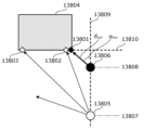
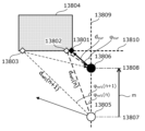
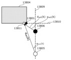
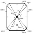
- Figures 1 to 3 assume the encoding of point groups generated by acquiring the three-dimensional positions of objects around the sensor centered around the sensor position, such as LiDAR. 1 to 3, for example, the second reference position 13808 of the sensor 13806 when measuring the point cloud of the encoding target frame, the first reference position 13807 of the sensor 13805 when measuring the point cloud of the reference frame, and The positional relationship between a conversion target point 13801 and reference candidate points 13802 and 13803 in inter prediction is shown.
- 1 to 3 show, for example, a sensor such as LiDAR that emits a laser around a predetermined axis (rotational axis) to measure the distance to an object, viewed from the axial direction. It is a plan view of the case.
- An encoding target point 13801 and reference candidate points 13802 and 13803 indicate three-dimensional positions on the same plane (for example, plane) 13810 of the object 13804 .
- An encoding target point 13801 is included in the point group of the encoding target frame.
- the point cloud of the frame to be encoded is indicated by black diamond-shaped points in FIGS.
- Candidate reference points 13802 and 13803 are included in the point cloud of the reference frame and included in a plurality of (eg, n+1) three-dimensional points indicating three-dimensional positions on the surface 13810 .
- the point cloud of the reference frame is indicated by the open diamond-shaped points in FIGS. 1-3.
- the sensor 13805 and the sensor 13806 may be the same sensor or different sensors (that is, separate sensors).
- the sensor 13805 and the sensor 13806 are the same sensor, for example, when one sensor moves from the first reference position 13807 to the second reference position 13808 or from the second reference position 13808 to the first reference position 13807 is.
- the time when the encoding target frame was generated differs from the time when the reference frame was generated.
- the sensor 13805 and the sensor 13806 are different sensors, the time at which the encoding target frame was generated and the time at which the reference frame was generated may be different or the same.
- the three-dimensional data encoding device calculates the predicted value d_pred of the distance d_cur from the second reference position 13808 of the sensor 13806 to the encoding target point 13801 as the second It is determined based on the positional relationship among the reference position 13808, the first reference position 13807 of the sensor 13805 during measurement of the point group of the reference frame, the encoding target point 13801, and the reference candidate points 13802 and 13803. Then, the 3D data encoding device may use the determined prediction value d pred for inter prediction. For example, the 3D data encoding device may determine the predicted value d pred by executing the following procedures 1 to 3. Since the 3D data decoding device determines the predicted value d pred by performing the same processing as the 3D data encoding device, only the 3D data encoding device will be described below.
- the three-dimensional data encoding device projects at least one reference candidate point 13802, 13803 onto the second polar coordinate system of the second reference position 13808, as shown in FIG.
- the horizontal angle ⁇ ref2 (i) of the i-th reference candidate point viewed from position 13808 is derived.
- ⁇ ref1 (i), d ref1 (i), and m are respectively the horizontal angle at the first reference position 13807 shown in FIG. 2, the distance from the first reference position 13807 to the i-th reference candidate point, and the distance between the first reference position 13807 and the second reference position 13808 (inter-sensor distance or movement distance).
- the horizontal angle is the angle of the direction in which the i-th reference candidate point exists with respect to the first reference position 13807, with reference to the reference direction 13809, which is the direction connecting the first reference position 13807 and the second reference position 13808.
- n is a natural number that can take i and k. i is any natural number.
- ⁇ ref2 (i) arctan( d ref1 (i) sin( ⁇ ref1 (i)) / (d ref1 (i) cos( ⁇ ref1 (i)) - m) ) (Formula Z1)
- the three-dimensional data encoding device selects from at least one horizontal angle ⁇ ref2 (i) corresponding to the i-th reference candidate point, the horizontal angle pointing from the second reference position 13808 to the encoding target point 13801.
- a horizontal angle ⁇ ref2 (k) near ⁇ cur is selected, and the k-th reference candidate point 13802 indicated by the horizontal angle ⁇ ref2 (k) is used for inter prediction (inter reference point ) 13811.
- k is a natural number indicating a horizontal angle near the horizontal angle ⁇ cur pointing from the second reference position 13808 to the encoding target point 13801 among n horizontal angles ⁇ ref2 . That is, the k-th reference candidate point is a reference point used for calculating the predicted value among the n reference candidate points, and is an example of the encoded first three-dimensional point.
- the 3D data encoding device derives the distance d ref2 (k) from the second reference position 13808 to the inter reference point 13811, and determines the distance d ref2 (k) as the predicted value d pred .
- the point group of the encoding target frame and the point group of the reference frame are expressed in polar coordinates of a coordinate system having different reference positions. Therefore, when the encoding target point 13801 is predictively encoded using the reference candidate points 13802 and 13803 of the reference frame different from the encoding target frame, the coordinate system of the reference candidate points 13802 and 13803 of the reference frame is set to the reference frame. It is necessary to perform a coordinate system transformation that transforms from a first coordinate system in which the point cloud of the coded frame is represented to a second coordinate system in which the point cloud of the encoded frame is represented.
- the three-dimensional data encoding device specifies the encoded first three-dimensional point whose position is represented by the first polar coordinates by executing procedures 1 to 3.
- FIG. The first 3D point is the reference point used for prediction.
- the three-dimensional data encoding device calculates the predicted value of the distance d cur from the second reference position 13808 of the uncoded second three-dimensional point whose position is expressed in the second polar coordinate system.
- the distance d cur is an example of the second distance.
- the distance m is an example of the distance between the first position and the second position.
- the horizontal angle ⁇ ref1 (k) is an example of the first angle and indicates the angle formed by the first line and the second line.
- the distance d ref1 (k) is an example of the first distance.
- the three-dimensional data encoding device uses the distance m, horizontal angle ⁇ ref1 (k), and Using the distance d ref1 (k), (iv) the horizontal angle ⁇ ref2 (k) between the first line and the third line connecting the second reference position 13808 and the reference point 13811, and (v) the second A distance d cur of the reference point 13811 in the polar coordinate system from the second reference position 13808 is calculated.
- the horizontal angle ⁇ ref2 (k) is an example of the second angle.
- the distance A horizontal angle ⁇ ref2 (k) is calculated using d ref1 (k) and the horizontal angle ⁇ ref1 (k) as the first angle.
- the horizontal angle ⁇ ref1 (k) is an example of a first horizontal angle, and is a horizontal angle component of the polar coordinate components representing the position of the reference point 13811 .
- the position of reference point 13811 is expressed in the first polar coordinate system.
- the device may calculate the difference between the horizontal angle component of the polar coordinate components representing the position of the reference point 13811 and the angle formed by the first line with respect to the reference line as the first angle.
- the three-dimensional data encoding device determines the first three-dimensional point based on the other second three-dimensional point whose position is expressed in the second polar coordinate system and which has already been encoded. may be specified.
- the three-dimensional data encoding device can highly accurately predict the distance d cur from the second reference position 13808 of the encoding target frame to the encoding target point 13801, and the efficiency of inter prediction encoding can be improved. could be improved.
- the movement distance m is the result of measurement using sensors such as GPS (Global Positioning System) and odometer, and using self-position estimation technology using SfM (Structure from Motion), SLAM (Simultaneous Localization and Mapping), etc. may be generated based on the results derived by Further, these results may be included in header information in predetermined data units such as frames and slices, and information on the head node of these data units. Thereby, these results may be notified from the 3D data encoding device to the 3D data decoding device.
- GPS Global Positioning System
- SfM Structure from Motion
- SLAM Simultaneous Localization and Mapping
- d ref2 (k) may be derived from equation Z3.
- the 3D data encoding apparatus may determine inter reference points by projecting all reference candidate points of the reference frame onto the second polar coordinate system of the second reference position 13808 of the encoding target frame.
- the 3D data encoding apparatus may perform the coordinate system transformation described above on all reference candidate points in the reference frame, and determine inter reference points based on all post-transformation candidate points.
- the 3D data encoding device may generate a horizontal angle ⁇ cur of the encoding target point 13801, the distance m between the first reference position 13807 and the second reference position 13808, and the like, and calculate the horizontal angle of the reference frame with respect to the sensor 13805.
- the reference candidate points may be limited to points included in a partial range of .
- the process of determining the inter reference point is not performed.
- the reference candidate points are limited to those located in an area ahead of the first reference position in the direction connecting the first reference position and the second reference position.
- the three-dimensional data encoding device limits the reference candidate points to be subjected to coordinate system conversion to a part of all the reference candidate points based on the horizontal angle ⁇ cur and the distance m. It is possible to suppress the amount of processing related to
- arithmetic processing such as trigonometric functions and division in each of the above procedures may be simplified by using a table consisting of a finite number of elements.
- the simplification makes it possible to improve the efficiency of inter prediction coding while suppressing the amount of processing.
- the angle formed by the reference direction 13809 in FIGS. 1 to 3 and the same plane (eg plane) 13810 of the object 13804 is not limited. That is, the direction of the first line connecting the first reference position 13807 and the second reference position 13808 can take any angle with respect to the horizontal axis included in the same plane (eg plane) 13810 of the object 13804 . Even in that case, the predicted value can be calculated using the above method.
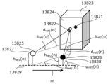
- FIG. 4 assumes encoding of a point group generated by acquiring the three-dimensional positions of objects around the sensor, centering on the sensor position, such as LiDAR.
- a predicted value d pred of the distance d cur from the sensor 13826 of the encoding target frame to the encoding target point 13821 may be determined by also considering ⁇ cur .
- the second reference position 13828 of the sensor 13826 of the encoding target frame, the first reference position 13827 of the sensor 13826 of the reference frame, the encoding target point 13821, and the reference candidate point 13822 in inter prediction Positional relationships are indicated.
- An encoding target point 13821 and a reference candidate point 13822 indicate three-dimensional positions on the same plane (for example, plane) 13824 of the object 13823 .
- the encoding target point 13821 is included in the point group of the encoding target frame.
- the point cloud of the frame to be encoded is indicated by black rhombic points in FIG.
- the reference candidate point 13822 is a three-dimensional point that is included in the point cloud of the reference frame and indicates the three-dimensional position of the object 13823 on the surface 13824 .
- a reference frame includes one or more 3D points, and may include multiple (eg, n) 3D points.
- the point cloud of the reference frame is indicated by the open diamond-shaped points in FIG.
- the sensors 13825 and 13826 may be the same sensor or different sensors (that is, different sensors). When the sensor 13825 and the sensor 13826 are the same sensor, for example, when one sensor moves from the first reference position 13827 to the second reference position 13828 or from the second reference position 13828 to the first reference position 13827 is.
- the time when the encoding target frame was generated differs from the time when the reference frame was generated.
- the sensor 13825 and the sensor 13826 are different sensors, the time at which the encoding target frame was generated and the time at which the reference frame was generated may be different or the same.
- the 3D data encoding device may determine the predicted value d pred by performing the following procedures 11 to 13.
- the three-dimensional data encoding device projects at least one reference candidate point 13822 onto the second polar coordinate system of the second reference position 13828, and calculates i
- the horizontal angle ⁇ ref2 (i) and the elevation angle ⁇ ref2 (i) of the th reference candidate point are derived.
- ⁇ ref2 (i), ⁇ ref2 (i), d ref1 (i), and m are respectively the horizontal angle and elevation angle at the first reference position 13827 shown in FIG.
- the distance to the reference candidate point and the distance between the first reference position 13827 and the second reference position 13828 are shown.
- the horizontal angle is the angle of the direction in which the i-th reference candidate point exists with respect to the first reference position 13827 with reference to the reference direction 13829 of the first reference position 13827 and the second reference position 13828 .
- the elevation angle is the angle of the direction in which the i-th reference candidate point exists with respect to the first reference position 13827 with respect to the horizontal plane.
- n is a natural number that can take i and k. i is any natural number.
- h ref1 (i) indicates the height of sensor 13825 from the reference plane
- h ref2 (i) indicates the height of sensor 13826 from the reference plane.
- the three-dimensional data encoding device encodes from the second reference position 13828 from among combinations of at least one horizontal angle ⁇ ref2 (i) and elevation angle ⁇ ref2 (i) corresponding to the reference candidate point 13822.
- the k-th reference candidate point 13822 indicated by the combination of k) is selected as a reference point (inter reference point) used for inter prediction.
- k is the horizontal angle ⁇ ref2 ( k ) and the elevation angle ⁇ ref2 (k). That is, the k-th reference candidate point is a reference point used for calculating the predicted value among the n reference candidate points, and is an example of the encoded first three-dimensional point.
- the three-dimensional data encoding device derives the distance d ref2 (k) from the second reference position 13828 to the reference candidate point 13822 selected as the inter reference point, and predicts the distance d ref2 (k). Determine as the value d pred .
- the three-dimensional data encoding device can accurately predict the distance d cur from the sensor 13826 of the encoding target frame to the encoding target point 13821, and the efficiency of inter prediction encoding can be improved. have a nature.
- d ref2 (k) may be derived from equation Z7 in procedure 13 above.
- the three-dimensional data encoding device may determine the inter reference point by projecting all reference candidate points of the reference frame onto the second polar coordinate system of the second reference position 13828 of the sensor 13826 of the encoding target frame. good. That is, the three-dimensional data encoding device may project all reference candidate points of the reference frame onto the second polar coordinate system of the second reference position, and determine inter reference points based on all post-transformation candidate points. .
- the three-dimensional data encoding device can detect the sensor 13825 of the reference frame based on the horizontal angle ⁇ cur or the elevation angle ⁇ cur of the encoding target point 13821, the distance m between the first reference position 13827 and the second reference position 13828, and the like.
- the reference candidate points may be limited to points included in a partial range of the horizontal angle and elevation angle with respect to . As a result, it is possible to reduce the amount of processing for determining inter reference points.
- the three-dimensional data encoding device limits reference candidate points to be subjected to coordinate system transformation to a part of all reference candidate points based on the horizontal angle ⁇ cur , elevation angle ⁇ cur , distance m, and the like. , the amount of processing involved in coordinate system conversion can be suppressed.
- arithmetic processing such as trigonometric functions and division in each of the above procedures may be simplified using a table having a finite number of elements.
- ⁇ ref2 (i) may be obtained from equation Z8 assuming that (h ref1 ( i ) ⁇ h ref2 (i))/d ref1 (i) is sufficiently small.
- ⁇ ref2 (i) arctan( tan( ⁇ ref1 (i)) sin( ⁇ ref2 (i))/sin( ⁇ ref1 (i)) ) (Formula Z8)
- FIG. 5 is a flowchart showing an example of the processing procedure of the inter prediction method.
- the 3D data encoding apparatus determines intra prediction points (d intra , ⁇ intra , ⁇ intra ) in the encoding target frame as reference points for inter prediction (S13801).
- the intra prediction information may be notified, and the prediction value obtained by the prediction method determined to be an appropriate intra prediction method may be used. may be omitted.
- the intra prediction point determined as the reference point for inter prediction may be a three-dimensional point used to calculate the predicted value of the three-dimensional point to be encoded in the second polar coordinate system.
- the 3D data encoding device projects the intra prediction points (d intra , ⁇ intra , ⁇ intra ) onto the first polar coordinate system of the reference frame, and the angle ( ⁇ sref , ⁇ sref ) are determined (S13802). Note that the angles ( ⁇ sref , ⁇ sref ) may be determined by Equations Z9 and Z10.
- the three-dimensional data encoding device converts one or more three-dimensional points having angles ( ⁇ ref1 (i), ⁇ ref1 (i)) near angles ( ⁇ sref , ⁇ sref ) in the reference frame to A reference candidate point is selected by a predetermined method (S13803).
- the three-dimensional data encoding device selects one or more laser scanning lines having an angle close to the elevation angle ⁇ sref , and selects laser scanning lines close to the elevation angle ⁇ sref in order of the horizontal angle ⁇ sref for each laser scanning line.
- One or more three-dimensional points may be selected, and the order of selection may be set as the index of the reference candidate point.
- the three-dimensional data encoding device projects the reference candidate points (d ref1 (i), ⁇ ref1 (i), ⁇ ref1 (i)) onto the second polar coordinate system at the second reference position of the encoding target frame. Then, the angle ( ⁇ ref2 (i), ⁇ ref2 (i)) in the encoding target frame is derived (S13804). Note that the angle ( ⁇ ref2 (i), ⁇ ref2 (i)) may be derived from equations Z11 and Z12.
- the three-dimensional data encoding device selects inter reference points ( ⁇ ref2 (k), ⁇ ref2 (k)) from angles ( ⁇ ref2 (i), ⁇ ref2 (i)) by a predetermined method.
- Select S13805
- the 3D data encoding apparatus may select a reference candidate point having an angle closest to the angle ( ⁇ cur , ⁇ cur ) as an inter reference point.
- the inter reference point is identified based on the angular component of the polar coordinate components representing the positions of other second three-dimensional points included in the encoding target frame.
- the inter-reference point is represented by the first polar coordinate system, and among the plurality of first three-dimensional points including other encoded first three-dimensional points, the inter reference point is the first polar coordinate system to the second
- the angle component of the plurality of projected first three-dimensional points after being projected onto the polar coordinate system is closest to the angle component of the point to be encoded.
- the three-dimensional data encoding device may notify the three-dimensional data decoding device of the index k of the inter reference point selected by a predetermined method.
- the 3D data encoding device derives the distance d ref2 (k) from the first reference position of the encoding target frame to the inter reference point, and determines the distance d ref2 (k) as the predicted value d pred . (S13806). Note that the distance d ref2 (k) may be derived by either formula Z13 or Z14.
- d ref2 (k) d ref1 (k) sin( ⁇ ref1 (k))/sin( ⁇ ref2 (k)) (equation Z13)
- d ref2 (k) (d ref1 (k)cos( ⁇ ref1 (k)) ⁇ m)/cos( ⁇ ref2 (k)) (equation Z14)
- the three-dimensional data encoding apparatus projects the intra prediction point of the encoding target frame onto the first polar coordinate system at the first reference position of the reference frame, and generates one or more inter reference point candidates based on the angle. may be selected.
- the number of reference candidate points used for inter prediction can be reduced, and the processing amount of inter prediction can be reduced.
- arithmetic processing such as trigonometric functions and division in the above procedure may be simplified using a table having a finite number of elements.
- inter prediction and intra prediction may be switched for each node or slice, or intra prediction or other inter prediction may be switched for each node or slice.
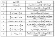
- FIG. 6 is a diagram for explaining a first example of switching the method of deriving the predicted value according to the value of the horizontal angle.
- FIG. 7 is a diagram showing a formula for deriving the predicted value d pred determined for each of the four directions defined by the horizontal angle ⁇ cur . Index in FIG. 7 indicates index values 0 to 3 corresponding to the virtual planes 13840 to 13843 set in FIG.
- a virtual plane perpendicular to a horizontal plane is set as an object in four directions, front, back, left , and right.
- the predicted value d pred is derived by the formula shown. That is, the 3D data encoding device acquires the horizontal angle ⁇ cur of the encoding target point and derives the predicted value d pred based on the equation corresponding to the horizontal angle ⁇ cur shown in FIG.
- ⁇ may be changed by being notified from the 3D data encoding device to the 3D data decoding device. Further, it is sufficient that the range to include the boundary line of each range is consistent between the encoding process and the decoding process, and does not necessarily have to be as shown in FIG. 7 .
- the three-dimensional data encoding apparatus includes a first determination method of a predicted value in predictive coding for a plurality of three-dimensional points on the first plane, and a predictive coding method for a plurality of three-dimensional points on the second plane. may be different from the second determination method of the predicted value in .
- predictive encoding is inter-prediction in which encoding target points of an encoding target frame are predictively encoded using reference candidate points of a reference frame different from the encoding target frame.
- the first plane is a plane facing the first reference position and the second reference position in the third direction, and is a plane perpendicular to the reference plane.
- the second plane is a plane facing the first reference position and the second reference position in the fourth direction, and is a plane perpendicular to the reference plane.
- the third direction and the fourth direction are directions different from each other.
- Some of the plurality of 3D points on the first plane are included in the plurality of first 3D points included in the reference frame.
- Some of the plurality of 3D points on the first plane are included in the plurality of second 3D points included in the encoding target frame.
- Some of the plurality of 3D points on the second plane are included in the plurality of first 3D points included in the reference frame.
- Another part of the plurality of 3D points on the second plane is included in the plurality of second 3D points included in the second frame.
- the distance d cur from the second reference position of the encoding target frame to the encoding target point is obtained from the point group obtained by the sensor 13845 of the reference frame at the first reference position which is the distance m from the second reference position. Based on this, prediction can be performed with higher precision than the inter prediction method described with reference to FIGS. 2 to 5, and the efficiency of inter prediction coding can be further improved.
- arithmetic processing such as trigonometric functions and division in FIG. 7 may be simplified by using a table consisting of a finite number of elements.
- the simplification makes it possible to improve the efficiency of inter prediction coding while suppressing the amount of processing.
- FIG. 8 is a diagram for explaining a second example in which the prediction value derivation method is switched according to the value of the horizontal angle.
- FIG. 9 is a diagram showing a formula for deriving the predicted value d pred determined for each of the eight directions defined by the horizontal angle ⁇ cur . Index in FIG. 9 indicates index values 0 to 7 corresponding to the virtual planes 13840 to 13843 set in FIG.
- a virtual plane perpendicular to a horizontal plane (reference plane) as an object is set in eight directions: four directions, front, back, left, and right, and four oblique directions between the four directions.
- a predicted value d pred is derived from the formula shown in FIG. 9 for each of the eight ranges divided by cur . That is, the 3D data encoding device acquires the horizontal angle ⁇ cur of the encoding target point and derives the predicted value d pred based on the equation corresponding to the horizontal angle ⁇ cur shown in FIG.
- ⁇ and ⁇ may be included in header information in predetermined data units such as sequences, frames, and slices. Accordingly, ⁇ and ⁇ may be notified from the 3D data encoding device to the 3D data decoding device and changed. In addition, it is sufficient that the range to include the boundary line of each range matches between the encoding process and the decoding process, and does not necessarily have to be as shown in FIG. 9 .
- the distance d cur from the second reference position of the encoding target frame to the encoding target point is calculated based on the point group obtained by the sensor 13845 of the reference frame at the first reference position which is the distance m from the sensor 13846.
- prediction can be performed with higher accuracy than the inter prediction methods described with reference to FIGS. 2 to 7, and the efficiency of inter prediction coding can be further improved.
- arithmetic processing such as trigonometric functions and division in FIG. 9 may be simplified by using a table consisting of a finite number of elements.
- the simplification may improve the efficiency of inter-prediction coding while suppressing the amount of processing.
- Three-dimensional data is, for example, point cloud data.
- a point cloud is a collection of a plurality of three-dimensional points and indicates the three-dimensional shape of an object.
- the point cloud data includes position information and attribute information of a plurality of 3D points.
- the position information indicates the three-dimensional position of each three-dimensional point.
- position information may also be called geometry information.
- positional information is represented by a rectangular coordinate system or a polar coordinate system.
- Attribute information indicates, for example, color, reflectance, or normal vector.
- One three-dimensional point may have one piece of attribute information or may have a plurality of pieces of attribute information.
- the three-dimensional data is not limited to point cloud data, and may be other three-dimensional data such as mesh data.
- Mesh data also referred to as three-dimensional mesh data
- CG Computer Graphics
- mesh data includes point cloud information (eg, vertex information). Therefore, the same method as the method corresponding to the point cloud data can be applied to this point cloud information.
- FIG. 10 is a block diagram showing the configuration of a three-dimensional data encoding device according to this embodiment.
- the three-dimensional data encoding device 100 supports inter-predictive encoding in which a point group to be encoded is encoded while referring to an encoded point group.
- This 3D data encoding apparatus 100 includes an encoding section 101, a motion compensation section 102, a first buffer 103, a second buffer 104, a switching section 105, and an inter prediction section .
- FIG. 10 only shows a configuration related to inter prediction encoding of position information
- the 3D data encoding device 100 includes other processing units related to encoding of position information (for example, an intra prediction unit, etc.). may be provided, or an attribute information encoding unit or the like for encoding attribute information may be provided.
- the encoding unit 101 generates a bitstream by encoding the target point group, which is the input point group to be encoded. Specifically, the encoding unit 101 extracts a prediction tree (predtree), which is a unit of encoding processing, from the target point group, and encodes each point included in the prediction tree while referring to inter prediction points. become The encoding unit 101 also outputs decoded points obtained by reproducing points obtained by decoding the bitstream. This decoding point is used for inter-prediction of subsequent points of interest (eg, points of interest of subsequent frames or slices).
- predtree a prediction tree
- This decoding point is used for inter-prediction of subsequent points of interest (eg, points of interest of subsequent frames or slices).
- the position information of the target point group and the position information of the decoding points are represented by, for example, polar coordinates.
- the position information of the target point group is represented by orthogonal coordinates, and the encoding unit 101 may convert the position information of the orthogonal coordinates into position information of polar coordinates, and encode the converted position information of polar coordinates.
- the motion compensation unit 102 performs motion compensation on the decoding points, and stores the motion-compensated reference point group (first reference point group) in the first buffer 103 .
- the motion compensation unit 102 performs motion compensation by projecting the position information of the decoding points onto the polar coordinates of the target point group using the inter prediction method in the polar coordinate system described in the first embodiment.
- motion compensation is correcting the position information of the decoding point according to the coordinate system of the target three-dimensional point to be encoded.
- motion compensation includes a process of aligning the origin of the coordinate system of the decoding point with the origin of the coordinate system of the target three-dimensional point, and moving each axis of the coordinate system of the decoding point to each of the coordinate systems of the target three-dimensional point. At least one of the alignment operations may be included.
- Motion compensation may also include coordinate calculations using translation vectors and rotation matrices.
- the decoded points (second reference point group without motion compensation) are stored in the second buffer 104 .
- the switching unit 105 switches one of the first reference point group stored in the first buffer 103 and the second reference point group stored in the second buffer 104 to inter reference points (third reference point group). , and outputs the inter reference point to inter prediction section 106 .
- the inter prediction unit 106 refers to at least one inter reference point stored in the first buffer 103 or the second buffer 104 to determine an inter prediction point.
- the inter prediction unit 106 refers to one or more inter reference points whose positions are the same as or close to the target point among a plurality of inter reference points included in a reference frame different from the target frame including the target point group.
- the inter reference point whose position is the same as or close to the target point is, for example, a point whose elevation angle index and horizontal angle index are the same as or close to the target point (for example, the index value is 1 larger or smaller).
- one 3D point in the reference point group may be selected as a prediction point, or a prediction point may be selected from a plurality of 3D points in the reference point group. may be calculated. For example, the average position of a plurality of 3D points may be calculated as the predicted point position.
- FIG. 11 is a block diagram showing the configuration of the three-dimensional data decoding device according to this embodiment.
- the three-dimensional data decoding device 200 supports inter-prediction decoding in which a point group to be decoded is decoded while referring to a decoded point group.
- This 3D data decoding device 200 comprises a decoding section 201 , a motion compensation section 202 , a first buffer 203 , a second buffer 204 , a switching section 205 and an inter prediction section 206 .
- 3D data decoding device 200 includes other processing units related to decoding of positional information (for example, an intra-prediction unit, etc.).
- an attribute information decoding unit or the like for decoding attribute information may be provided.
- the decoding unit 201 generates a decoded point group by decoding the input bitstream. Specifically, decoding section 201 decodes each point in the prediction tree while referring to the inter prediction point, and outputs the obtained decoding point.
- the motion compensation unit 202, the first buffer 203, the second buffer 204, the switching unit 205, and the inter-prediction unit 206 each operate in the motion compensation unit included in the three-dimensional data encoding apparatus 100 shown in FIG.
- the operations of the section 102, the first buffer 103, the second buffer 104, the switching section 105, and the inter prediction section 106 are the same.
- FIG. 12 is a flowchart showing an example of a processing procedure for encoding or decoding a frame to which inter prediction processing is applied in the 3D data encoding device 100 and the 3D data decoding device 200 shown in FIGS. 10 and 11. .
- the processing shown in FIG. 12 may be repeatedly performed for each frame, or may be repeatedly performed for each processing unit (for example, slice) obtained by dividing a frame.
- the three-dimensional data encoding device 100 and the three-dimensional data decoding device 200 compare the coordinates of the processed point group that has been encoded or decoded and the coordinates of the target point group to be encoded or decoded. Acquire motion information about the displacement between (S101).
- the three-dimensional data encoding device 100 uses an alignment technique such as the ICP (Iterative Closest Point) algorithm to rotate and/or parallelize the coordinates of the processed point group and the target point group. Displacement such as movement is detected, and motion information is determined based on the detected displacement.
- the 3D data encoding apparatus 100 stores motion information in upper syntax (SPS, GPS, slice header, etc.) of the bitstream.
- SPS Sequence Parameter Set
- GPS Global System for Mobile Communications
- the motion information includes, for example, at least one of information about movement parallel to the horizontal plane and information about rotation about the vertical axis.
- the motion information includes, for example, a 3 ⁇ 1 translation matrix.
- the motion information includes the absolute value (
- the motion information includes, for example, a 3x3 rotation matrix.
- the motion information indicates the rotation angle (angle ⁇ described later) of the coordinate axis on the horizontal plane and the rotation around the vertical axis.
- the 3D data decoding device 200 acquires motion information from the bitstream, and performs displacement such as rotation and/or translation between the coordinates of the processed point group and the coordinates of the target point group based on the acquired motion information. set.
- the 3D data encoding device 100 and the 3D data decoding device 200 project at least part of the first processed point group onto the coordinates of the target point group according to the motion information, and the obtained points A cloud is set as a first reference point cloud (S102).
- the inter-prediction method in the polar coordinate system described with reference to FIGS. 1 to 9 in Embodiment 1 may be used.
- the first processed point group is a processed point group included in one frame or one slice.
- the first processed point cloud may be a processed point cloud included in multiple frames or multiple slices.
- the above projection may be performed on all of the distance component, horizontal angle component, and elevation angle component included in the position information, or may be performed on some of them. For example, only the distance component and the horizontal angle component are changed to the values projected from the first processed point cloud to the coordinates of the target point cloud, and the elevation angle component is not changed as the value of the first processed point cloud. good too. Thereby, the amount of processing can be reduced.
- step S103 the 3D data encoding device 100 and the 3D data decoding device 200 directly convert the coordinate information of the second processed point group to the coordinate information of the target point group for at least part of the second processed point group. is set as a second reference point group (S103). Note that step S103 may be performed before step S101 or S102.
- the first processed point group and the second processed point group may be included in the same processing unit (same frame, same slice, etc.) or may be included in different processing units.
- the first processed point cloud and the second processed point cloud may be the corrected (post-projected) point cloud and the uncorrected point cloud of the point cloud included in the same processing unit.
- the point group of this processing unit is the point group whose time is closest to the target point group.
- the second processed point cloud is the point cloud whose time is closest to the target point cloud
- the first processed point cloud is another point cloud whose time is different from the second processed point cloud.
- the three-dimensional data encoding apparatus 100 determines which time point group to use for each of the first processed point group and the second processed point group, and information indicating the determined content, It may be stored in a bitstream higher level syntax (SPS, GPS, slice header, etc.).
- the information includes the time distance between the target point cloud and the point cloud used as the first processed point cloud, and the time distance between the target point cloud and the point cloud used as the second processed point cloud. This is the information shown. Note that when a point cloud common to the first processed point cloud and the second processed point cloud is used, the information may indicate the common point cloud.
- the information may be set for each processing unit (for example, slice or frame).
- the 3D data encoding device 100 can select a processed point group that is suitable for characteristics such as time change of the target point group, which may improve the encoding efficiency.
- the 3D data encoding device 100 and the 3D data decoding device 200 determine an inter-prediction point group for each point, and refer to the inter-prediction points to encode or decode the target point (S104 to S107). .
- the 3D data encoding device 100 and the 3D data decoding device 200 start loop processing for each target point included in the target point group (S104). That is, one of the plurality of points included in the target point group is selected as the target point to be processed.
- the 3D data encoding device 100 and the 3D data decoding device 200 refer to at least part of the reference point group including the first reference point group and the second reference point group to correspond to the target point.
- Inter prediction points to be used are determined (S105).
- the 3D data encoding device 100 and the 3D data decoding device 200 select one of a plurality of inter-reference points included in a reference frame different from the target frame containing the target point group, the position of which is the same as or close to the target point. See the inter-reference points above.
- the inter reference point whose position is the same as or close to the target point is, for example, a point whose elevation angle index and horizontal angle index are the same as or close to the target point (for example, the index value is 1 larger or smaller).
- the three-dimensional data encoding device 100 uses the code amount (residual error) when using inter prediction points determined using the first processed point group, and the second processed point group The amount of code (residual error) when the determined inter prediction point is used is compared, and the one with the smaller amount of code is determined to be selected (referenced). Note that the 3D data encoding apparatus 100 may refer to the first processed point group and the second processed point group to determine the inter prediction point with the smallest code amount.
- whether to use the first processed point group or the second processed point group may be determined according to the characteristics of the target point or the target point group.
- the 3D data encoding device 100 stores information indicating whether to use the first processed point group or the second processed point group, or information indicating inter prediction points in the bitstream, The 3D data decoding device 200 may refer to this information to determine whether to use the first processed point group or the second processed point group, or to determine inter-prediction points.
- the 3D data encoding device 100 encodes the target point with reference to this inter prediction point (S106). Specifically, the 3D data encoding apparatus 100 calculates a residual (difference) between the position information of the target point and the position information of the inter prediction point. The three-dimensional data encoding device 100 generates encoded position information by performing quantization and entropy encoding on the obtained residual. Note that the residual of some of the components of the position information (for example, the distance, the elevation angle, and the horizontal angle) may be calculated, and the original values of the other components may be quantized and entropy-encoded as they are. . Also, the 3D data encoding device 100 generates a bitstream including encoded position information.
- the target point is decoded with reference to this inter prediction point. Specifically, the 3D data decoding device 200 acquires encoded position information of the target point from the bitstream. The 3D data decoding device 200 generates a residual of the target point by performing entropy decoding and inverse quantization on the encoded position information of the target point. The 3D data decoding device 200 generates the position information of the target point by adding the residual of the target point and the position information of the inter prediction point.
- the 3D data encoding device 100 and the 3D data decoding device 200 end loop processing for the target point (S107). That is, steps S105 and S106 are performed for each of the plurality of points included in the target point group.
- the 3D data encoding device 100 and the 3D data decoding device 200 do not always have to refer to inter prediction points to encode or decode target points.
- the 3D data encoding apparatus 100 may store switching information indicating whether to refer to inter prediction points for each node or slice in a bitstream.
- the 3D data decoding device 200 can switch whether to refer to inter prediction points based on the information.
- step S105 may be omitted if the inter prediction point is not referred to. In this way, by making it possible to switch whether to refer to inter prediction points or not, the 3D data encoding device 100 can select an encoding method suitable for characteristics such as time change of the target point cloud. Coding efficiency may be improved.
- FIG. 13 is a diagram for explaining an example of an inter prediction method when performing encoding or decoding using polar coordinates.
- the motion compensation unit 102 shown in FIG. 10 and the motion compensation unit 202 shown in FIG. 11 or in step S102 shown in FIG. Predictive methods may be used. That is, FIG. 13 shows an example of motion compensation.
- the motion vector mv is the displacement on the horizontal plane from the polar coordinate origin of the target frame to be encoded or decoded (frame to be processed) to the polar coordinate origin of the reference frame.
- the angle ⁇ (alpha) is the angle formed by the motion vector mv with respect to the reference direction of the horizontal angle of the target frame.
- the angle ⁇ (beta) is the angle between the reference direction of the horizontal angle of the target frame and the reference direction of the horizontal angle of the reference frame.
- the 3D data encoding device 100 and the 3D data decoding device 200 predict the horizontal angle in the polar coordinates of the target frame.
- the value ⁇ ref2 (n) and the predicted distance value d ref2 (n) may be determined using Equations 1 and 2 below.
- is the magnitude of the motion vector mv.
- ⁇ ref2 (n) arctan(d ref1 (n) sin( ⁇ ref1 (n) ⁇ + ⁇ )/(d ref1 (n) cos( ⁇ ref1 (n) ⁇ + ⁇ )+
- d ref2 (n) d ref1 (n) sin( ⁇ ref1 (n) ⁇ + ⁇ )/sin( ⁇ ref2 (n) ⁇ ) (equation 2)
- the 3D data encoding device 100 and the 3D data decoding device 200 may determine d ref2 (n) using the following (Formula 3) instead of (Formula 2). Note that, when the denominator of division in one of (Equation 2) and (Equation 3) is 0 (zero), three-dimensional data encoding device 100 and three-dimensional data decoding device 200 use the other equation to obtain d ref2 (n) may be determined.
- d ref2 (n) (d ref1 (n)cos( ⁇ ref1 (n) ⁇ + ⁇ )+
- the three-dimensional data encoding device 100 and the three-dimensional data decoding device 200 can highly accurately predict the distance from the polar coordinate origin of the target frame to the target point. This may improve the efficiency of inter prediction coding.
- the predicted value ⁇ ref2 (n) of the elevation angle in the polar coordinates of the target frame may be determined using (Equation Z5) shown in the first embodiment. This may further improve the efficiency of inter prediction encoding.
- the elevation angle ⁇ ref1 (n) in the polar coordinates of the reference frame or its index information may be used as it is as the elevation angle prediction value ⁇ ref2 (n) or its index information. As a result, there is a possibility that the efficiency of inter prediction coding can be improved while suppressing the amount of processing.
- ⁇ ref2 (n) atan2(d ref1 (n) sin( ⁇ ref1 (n) ⁇ + ⁇ ), d ref1 (n) cos( ⁇ ref1 (n) ⁇ + ⁇ )+
- Atan2(0,0) is indefinite
- the angle ⁇ formed by the reference direction of the horizontal angle of the reference frame with respect to the reference direction of the horizontal angle of the motion vector mv and the target frame is (1) measured using a sensor such as a GPS (Global Positioning System) or an odometer, (2) Using at least one of self-position estimation technology using SfM (Structure from Motion) or SLAM (Simultaneous Localization and Mapping), and (3) Alignment technology such as ICP (Iterative Closest Point) algorithm It may be determined based on the derived result.
- a sensor such as a GPS (Global Positioning System) or an odometer
- SfM Structure from Motion
- SLAM Simultaneous Localization and Mapping
- Alignment technology such as ICP (Iterative Closest Point) algorithm It may be determined based on the derived result.
- the 3D data encoding apparatus 100 uses, as motion information, a motion vector mv and an angle ⁇ formed by the reference direction of the horizontal angle of the reference frame with respect to the reference direction of the horizontal angle of the target frame, or information about these values. It may be stored in the header information in units such as slices. Instead of the motion vector mv, the 3D data encoding apparatus 100 stores the magnitude
- FIG. 14 is a flowchart of inter prediction processing. Further, FIG. 14 shows an example of the procedure for deriving the predicted value ⁇ ref2 (n) of the horizontal angle and the predicted value d ref2 (n) of the distance in the polar coordinates of the target frame in the inter prediction method described using FIG. is. Note that the horizontal angle in this example takes a value within the range of - ⁇ to ⁇ . For example, in steps S121 and S129 shown in FIG. 14, 2 ⁇ is added to the result if the result is less than - ⁇ , and 2 ⁇ is subtracted from the result if the result is greater than ⁇ .
- the operation of the 3D data encoding device 100 will be described below, the operation of the 3D data decoding device 200 is the same.
- the three-dimensional data encoding apparatus 100 first sets ⁇ ′ ref1 (n) to ⁇ ref1 (n) ⁇ + ⁇ (S121).
- ⁇ ′ ref2 (n) arctan(d ref1 (n) sin( ⁇ ′ ref1 (n))/(d ref1 (n) cos( ⁇ ′ ref1 (n))+
- ⁇ ′ ref2 (n) arctan(d ref1 (n) sin( ⁇ ′ ref1 (n))/(d ref1 (n) cos( ⁇ ′ ref1 (n))+
- ⁇ ′ ref2 (n) sign( ⁇ ′ ref1 (n)) ⁇ /2 (Formula 7)
- ⁇ ′ ref2 (n) 0 (Formula 8)
- 3D data encoding apparatus 100 sets ⁇ /2 ⁇ ′ It is determined that ref2 (n) ⁇ /2, and ⁇ ′ ref2 (n) is obtained by executing (Equation 5) (S123).
- >0 is not satisfied (False in S122) and d ref1 (n) cos( ⁇ ′ ref1 (n))+
- the 3D data encoding apparatus 100 determines that tan is not defined, and executes (Equation 8) to obtain ⁇ ′ ref2 ( n) is set to a constant (for example, 0) (S128).
- the three-dimensional data encoding apparatus 100 uses ⁇ ′ ref2 (n) obtained above to set ⁇ ref2 (n) to ⁇ ′ ref2 (n)+ ⁇ (S129).
- the three-dimensional data encoding apparatus 100 determines in which angular range ⁇ ′ ref1 (n) lies, and derives d ref2 (n) using (Equation 9) or (Equation 10).
- d ref2 (n) d ref1 (n) sin( ⁇ ′ ref1 (n))/sin( ⁇ ′ ref2 (n)) (equation 9)
- d ref2 (n) (d ref1 (n) cos( ⁇ ′ ref1 (n))+
- 3D data encoding apparatus 100 assumes that the reference point is not positioned on a straight line containing motion vector mv. Then, d ref2 (n) is obtained by executing (Expression 9) (S131). On the other hand, if sin( ⁇ ′ ref2 (n)) is 0 (False in S130), the 3D data encoding device 100 determines that the reference point is located on a straight line containing the motion vector mv, (Equation 10) is executed to obtain d ref2 (n) (S132).
- the displacement on the horizontal plane from the polar coordinate origin of the target frame of the encoding/decoding process (processing target frame) to the polar coordinate origin of the reference frame is
- the three-dimensional data Encoding apparatus 100 may use only non-motion-compensated reference points for inter prediction, and may omit storing accompanying information, such as information on selection of inter reference points, in the bitstream.
- the 3D data encoding device 100 and the 3D data decoding device 200 may use a point group at another time without motion compensation as the reference point group instead of the motion compensated reference point group.
- the encoding efficiency can be maintained or improved while suppressing the amount of processing in the encoding of a scene in which a moving body equipped with a sensor is stationary.
- the 3D data encoding device 100 may store information indicating whether or not to use the motion-compensated reference point group for inter prediction in the upper syntax (SPS, GPS, slice header, etc.). Further, when the 3D data encoding device 100 and the 3D data decoding device 200 do not use the motion-compensated reference point groups for inter prediction, the 3D data encoding apparatus 100 and the 3D data decoding apparatus 200 use one or more non-motion-compensated reference point groups for inter prediction. may be used. As a result, the operation of the three-dimensional data encoding apparatus 100 and the flexibility of encoding algorithm design are increased, and the operability and encoding efficiency of the apparatus may be improved.
- the 3D data encoding device 100 and the 3D data decoding device 200 may project all inter reference point candidates included in the reference frame onto the polar coordinate origin of the target frame, or may project only some of the points. It may be projected onto the polar origin of the frame. For example, some of the points are points whose elevation angle with respect to the origin of the polar coordinates of the reference frame is above (larger) a predetermined value, or vertical (z-axis direction) positions when the reference frame is expressed in Cartesian coordinates. is located above a pre-determined position (eg the ground). As a result, it is possible to narrow down the object to be processed to a structure such as a building or a wall, for which a large improvement in encoding efficiency can be expected by projection.
- the horizontal angle with respect to the origin of the polar coordinates of the reference frame may be divided (quantized) by a predetermined angle, and inter-reference point candidates may be limited to representative points of each angle interval. This may further reduce the amount of processing and the amount of memory.
- the 3D data encoding device 100 and the 3D data decoding device 200 rotate and/or translate the processed point group in the Cartesian coordinate space, so that the coordinate in the Cartesian coordinate space of the target point group of the processed point group may be obtained, the coordinates of the obtained processed point group may be converted into coordinates in the polar coordinate space of the target point group, and the obtained point group may be set as a motion-compensated reference point group.
- a common motion compensation method can be used for encoding a point group represented by orthogonal coordinates using an octree or a prediction tree and for encoding a point group represented by polar coordinates. Therefore, since the structure of the three-dimensional data encoding device and the three-dimensional data decoding device can be simplified, there is a possibility that the scale of the circuit or software can be suppressed.
- arithmetic processing such as trigonometric functions and division in inter-prediction may be simplified by using approximation by integer precision processing or by using a table with a finite number of elements. These simplifications may improve the efficiency of point cloud coding while reducing the amount of processing and memory required for projection.
- At least part of the apparatus, processing, or syntax described above may be used to encode vertex information of a three-dimensional mesh.
- processing can be shared between point group encoding and three-dimensional mesh encoding, so there is a possibility that the scale of circuits or software can be suppressed.
- the three-dimensional data encoding device performs the processing shown in FIG.
- a three-dimensional data encoding device corrects (motion compensation) position information of one or more first three-dimensional points in accordance with a coordinate system of a target three-dimensional point to be encoded, thereby generating a first reference point group. (S201), and one of the first reference point group and the second reference point group including the one or more first 3D points before correction is used as a third reference point for the target 3D point.
- S202 determine predicted points using a third reference point group (S203), determine at least part of position information of the predicted points (for example, at least part of a plurality of components included in the position information) ) to encode the position information of the target three-dimensional point (S204).
- the 3D data encoding device may determine prediction points for the target 3D point from the first reference point group and the second reference point group instead of steps S202 and S203.
- the three-dimensional data encoding device selectively uses the corrected first reference point group and the second reference point group before correction to encode the target points. Therefore, the 3D data encoding device may be able to determine prediction points that reduce the prediction error. Therefore, the 3D data encoding device can improve the encoding efficiency. Also, the three-dimensional data encoding device can suppress the amount of data handled in the encoding process.
- the 3D data encoding apparatus uses first information (for example, motion information ), the position information of the one or more first three-dimensional points is aligned with the coordinate system of the target three-dimensional point.
- first information for example, motion information
- the three-dimensional data encoding device projects one or more first three-dimensional points onto the coordinate origin of the target three-dimensional point according to the displacement, thereby forming the first reference point group position information of one or more second three-dimensional points included in .
- the first information includes at least one of second information about movement parallel to the horizontal plane and third information about rotation about the vertical axis.
- the position information includes a distance component, a horizontal angle component and an elevation angle component
- the 3D data encoding device corrects at least one of the distance component and the horizontal angle component in correction (S201).
- the three-dimensional data encoding device can efficiently correct the three-dimensional data obtained by the horizontally moving sensor. That is, in this aspect, the elevation component in polar coordinates is not corrected. Therefore, this aspect is suitable for selectively using the reference point group whose position is corrected in the horizontal direction and the reference point group before correction. For example, this aspect is suitable for 3D point clouds obtained with a sensor that repeatedly moves and stops in the horizontal direction.
- the three-dimensional data encoding device further determines whether or not to perform the correction, and bit including position information of the encoded target three-dimensional point and fourth information indicating whether or not to perform the correction. Generate a stream. According to this, the three-dimensional data encoding device can determine a prediction point that reduces the prediction error by switching whether to perform correction or not. For example, the 3D data encoding device can select an appropriate technique according to the characteristics of the point group to be processed.
- the fourth information may be a flag or a parameter. Further, the fourth information may be provided for each frame, may be provided for each processing unit (for example, slice) in the frame, or may be provided for each point.
- the three-dimensional data encoding device selects the second reference point group as the third reference point group when correction is not performed.
- one or more first 3D points are included in a first processing unit (eg, frame or slice), and the 3D data encoding device, if no correction is performed, a second reference point group and a fourth reference point group which is one or more third three-dimensional points included in a second processing unit different from the first processing unit and which is the one or more third three-dimensional points before correction as the third reference point group.
- the three-dimensional data encoding device can refer to two processing units (for example, two frames) without correction when correction is not performed. Therefore, the 3D data encoding device can improve the encoding efficiency.
- the first reference point group is generated by correcting one or more fourth three-dimensional points that are part of one or more first three-dimensional points.
- the 3D data encoding device can reduce the amount of processing by limiting the 3D points to be corrected. For example, if the relative positional relationship between the target 3D point and the origin is approximately the same as the relative positional relationship between the predicted point and the origin included in the reference point group, the prediction error is can be suppressed. On the other hand, if the relative positional relationship between the target 3D point and the origin differs from the relative positional relationship between the predicted points included in the reference point group and the origin, the predicted error can be suppressed by using the corrected predicted points. can be done. In this way, by switching whether or not correction should be performed depending on the position of the target three-dimensional point, the prediction error can be reduced.
- the position information includes a distance component, a horizontal angle component, and an elevation angle component
- the fourth three-dimensional point is the first three-dimensional point having an elevation angle component larger than a predetermined value among the one or more first three-dimensional points.
- a three-dimensional point with a large elevation angle component represents, for example, a building. The building is fixed on the ground. Therefore, when the target 3D point and the predicted point represent a building, the relative positional relationship between the target 3D point and the origin differs from the relative positional relationship between the predicted point and the origin included in the reference point group. In this case, prediction errors can be suppressed by using corrected prediction points. Therefore, the three-dimensional data encoding device limits the objects to be corrected to buildings and the like.
- the fourth three-dimensional point is the first three-dimensional point whose vertical position is higher than the predetermined position among the one or more first three-dimensional points.
- a three-dimensional data encoding device includes a processor and memory, and the processor uses the memory to perform the above processing.
- the three-dimensional data decoding device performs the processing shown in FIG.
- a three-dimensional data decoding device generates a first reference point group by correcting (motion compensation) position information of one or more first three-dimensional points in accordance with a coordinate system of a target three-dimensional point to be decoded.
- one of the first reference point group and the second reference point group including one or more first 3D points before correction is converted into a third reference point group for the target 3D point;
- (S212) determine the prediction point using the third reference point group (S213), and at least part of the position information of the prediction point (for example, at least part of the plurality of components included in the position information)
- the position information of the target three-dimensional point is decoded by referring to it (S214).
- the 3D data decoding device may determine prediction points for the target 3D point from the first reference point group and the second reference point group instead of steps S212 and S213.
- the three-dimensional data decoding device selectively uses the corrected first reference point group and the second reference point group before correction to decode the target point. Therefore, the three-dimensional data decoding device may be able to determine prediction points that reduce the prediction error. Therefore, the three-dimensional data decoding device can suppress the amount of data handled in the decoding process.
- the three-dimensional data decoding device uses first information (for example, motion information) indicating the displacement between the coordinate system of one or more first three-dimensional points and the coordinate system of the target three-dimensional point.
- Position information of one or more first three-dimensional points is aligned with the coordinate system of the target three-dimensional point.
- the three-dimensional data decoding device projects one or more first three-dimensional points onto the coordinate origin of the target three-dimensional point according to the displacement, thereby forming the first reference point group. Deriving position information for one or more of the included second 3D points.
- the first information includes at least one of second information about movement parallel to the horizontal plane and third information about rotation about the vertical axis.
- the three-dimensional data decoding device can efficiently correct the three-dimensional data obtained by the horizontally moving sensor.
- the position information includes a distance component, a horizontal angle component and an elevation angle component
- the 3D data decoding device corrects at least one of the distance component and the horizontal angle component in correction (S211). That is, in this aspect, the elevation component in polar coordinates is not corrected. Therefore, this aspect is suitable for selectively using the reference point group whose position is corrected in the horizontal direction and the reference point group before correction. For example, this aspect is suitable for 3D point clouds obtained with a sensor that repeatedly moves and stops in the horizontal direction.
- the 3D data decoding device further acquires fourth information indicating whether or not to perform correction from the bitstream, and determines whether or not to perform correction based on the fourth information.
- the three-dimensional data decoding device can determine a prediction point that reduces the prediction error by switching whether to perform correction or not.
- the fourth information may be a flag or a parameter.
- the fourth information may be provided for each frame, may be provided for each processing unit (for example, slice) in the frame, or may be provided for each point.
- the three-dimensional data decoding device selects the second reference point group as the third reference point group when correction is not performed.
- one or more first 3D points are included in a first processing unit (for example, frame or slice), and the 3D data decoding device, in the case of not performing correction, a second reference point group and , a fourth reference point group which is one or more third three-dimensional points included in a second processing unit different from the first processing unit and which is the one or more third three-dimensional points before correction; is selected as the third reference point cloud.
- the three-dimensional data decoding device can refer to two processing units (for example, two frames) without correction when correction is not performed. Therefore, the 3D data decoding device can improve the encoding efficiency.
- the first reference point group is generated by correcting one or more fourth three-dimensional points that are part of one or more first three-dimensional points.
- the 3D data decoding device can reduce the amount of processing by limiting the 3D points to be corrected. For example, if the relative positional relationship between the target 3D point and the origin is approximately the same as the relative positional relationship between the predicted point and the origin included in the reference point group, the prediction error is can be suppressed. On the other hand, if the relative positional relationship between the target 3D point and the origin differs from the relative positional relationship between the predicted points included in the reference point group and the origin, the predicted error can be suppressed by using the corrected predicted points. can be done. In this way, by switching whether or not correction should be performed depending on the position of the target three-dimensional point, the prediction error can be reduced.
- the position information includes a distance component, a horizontal angle component, and an elevation angle component
- the fourth three-dimensional point is the first three-dimensional point having an elevation angle component larger than a predetermined value among the one or more first three-dimensional points.
- a three-dimensional point with a large elevation angle component represents, for example, a building. The building is fixed on the ground. Therefore, when the target 3D point and the predicted point represent a building, the relative positional relationship between the target 3D point and the origin differs from the relative positional relationship between the predicted point and the origin included in the reference point group. In this case, prediction errors can be suppressed by using corrected prediction points. Therefore, in the three-dimensional data decoding method, the objects to be corrected are limited to buildings and the like.
- the fourth three-dimensional point is the first three-dimensional point whose vertical position is higher than the predetermined position among the one or more first three-dimensional points.
- a three-dimensional data decoding device includes a processor and memory, and the processor uses the memory to perform the above processing.
- each processing unit included in the three-dimensional data encoding device, the three-dimensional data decoding device, etc. according to the above embodiments is typically realized as an LSI, which is an integrated circuit. These may be made into one chip individually, or may be made into one chip so as to include part or all of them.
- circuit integration is not limited to LSIs, and may be realized with dedicated circuits or general-purpose processors.
- An FPGA Field Programmable Gate Array
- a reconfigurable processor that can reconfigure the connections and settings of the circuit cells inside the LSI may be used.
- each component may be configured with dedicated hardware or realized by executing a software program suitable for each component.
- Each component may be realized by reading and executing a software program recorded in a recording medium such as a hard disk or a semiconductor memory by a program execution unit such as a CPU or processor.
- the present disclosure may be implemented as a three-dimensional data encoding method, a three-dimensional data decoding method, or the like executed by a three-dimensional data encoding device, a three-dimensional data decoding device, or the like.
- the division of functional blocks in the block diagram is an example, and a plurality of functional blocks can be realized as one functional block, one functional block can be divided into a plurality of functional blocks, and some functions can be moved to other functional blocks.
- single hardware or software may process the functions of a plurality of functional blocks having similar functions in parallel or in a time-sharing manner.
- each step in the flowchart is executed is for illustrative purposes in order to specifically describe the present disclosure, and orders other than the above may be used. Also, some of the above steps may be executed concurrently (in parallel) with other steps.
- the present disclosure can be applied to a 3D data encoding device and a 3D data decoding device.
Abstract
In this three-dimensional data encoding method, a first reference point group is generated (S201) by correcting the position information of one or more first three-dimensional points in accordance with the coordinate system of a target three-dimensional point to be encoded, one of the first reference point group and a second reference point group including the one or more three-dimensional points prior to correction is selected (S202) as a third reference point group for the target three-dimensional point, a prediction point is determined (S203) using the third reference point group, and at least some of the position information of the prediction point is referenced and the position information of the target three-dimensional point is encoded (S204).
Description
本開示は、三次元データ符号化方法、三次元データ復号方法、三次元データ符号化装置、及び三次元データ復号装置に関する。
The present disclosure relates to a three-dimensional data encoding method, a three-dimensional data decoding method, a three-dimensional data encoding device, and a three-dimensional data decoding device.
自動車或いはロボットが自律的に動作するためのコンピュータビジョン、マップ情報、監視、インフラ点検、又は、映像配信など、幅広い分野において、今後、三次元データを活用した装置又はサービスの普及が見込まれる。三次元データは、レンジファインダなどの距離センサ、ステレオカメラ、又は複数の単眼カメラの組み合わせなど様々な方法で取得される。
In the future, it is expected that devices or services that utilize 3D data will spread in a wide range of fields, such as computer vision, map information, monitoring, infrastructure inspection, or video distribution for autonomous operation of automobiles or robots. Three-dimensional data is acquired in various ways, such as range sensors such as range finders, stereo cameras, or a combination of multiple monocular cameras.
三次元データの表現方法の1つとして、三次元空間内の点群によって三次元構造の形状を表すポイントクラウドと呼ばれる表現方法がある。ポイントクラウドでは、点群の位置と色とが格納される。ポイントクラウドは三次元データの表現方法として主流になると予想されるが、点群はデータ量が非常に大きい。よって、三次元データの蓄積又は伝送においては二次元の動画像(一例として、MPEGで規格化されたMPEG-4 AVC又はHEVCなどがある)と同様に、符号化によるデータ量の圧縮が必須となる。
As one of the three-dimensional data representation methods, there is a representation method called a point cloud that expresses the shape of a three-dimensional structure using a point group in a three-dimensional space. A point cloud stores the position and color of the point cloud. Point clouds are expected to become mainstream as a method of expressing three-dimensional data, but point clouds have a very large amount of data. Therefore, in the storage or transmission of 3D data, it is essential to compress the amount of data by encoding, as with 2D moving images (one example is MPEG-4 AVC or HEVC standardized by MPEG). Become.
また、ポイントクラウドの圧縮については、ポイントクラウド関連の処理を行う公開のライブラリ(Point Cloud Library)などによって一部サポートされている。
In addition, point cloud compression is partially supported by a public library (Point Cloud Library) that performs point cloud-related processing.
また、三次元の地図データを用いて、車両周辺に位置する施設を検索し、表示する技術が知られている(例えば、特許文献1参照)。
Also, there is known a technique of searching for and displaying facilities located around a vehicle using three-dimensional map data (see Patent Document 1, for example).
三次元データの符号化処理及び復号処理では、符号化効率を向上することが望まれている。
In encoding and decoding of 3D data, it is desired to improve the encoding efficiency.
本開示は、符号化効率を向上できる三次元データ符号化方法、三次元データ復号方法、三次元データ符号化装置、及び三次元データ復号装置を提供することを目的とする。
An object of the present disclosure is to provide a 3D data encoding method, a 3D data decoding method, a 3D data encoding device, and a 3D data decoding device that can improve encoding efficiency.
本開示の一態様に係る三次元データ符号化方法は、(出願までに請求項1の記載を貼り付けます。以下同様。)。
The three-dimensional data encoding method according to one aspect of the present disclosure is (the description of claim 1 is pasted before filing; the same shall apply hereinafter).
本開示の一態様に係る三次元データ復号方法は、(請求項12)。
A three-dimensional data decoding method according to one aspect of the present disclosure is (claim 12).
本開示は、符号化効率を向上できる三次元データ符号化方法、三次元データ復号方法、三次元データ符号化装置、及び三次元データ復号装置を提供できる。
The present disclosure can provide a 3D data encoding method, a 3D data decoding method, a 3D data encoding device, and a 3D data decoding device that can improve encoding efficiency.
本開示の一態様に係る三次元データ符号化方法は、1以上の第1の三次元点の位置情報を符号化対象の対象三次元点の座標系に合わせて補正することで第1の参照点群を生成し、前記第1の参照点群と、補正前の前記1以上の第1の三次元点を含む第2の参照点群との一方を、前記対象三次元点のための第3の参照点群として選択し、前記第3の参照点群を用いて予測点を決定し、前記予測点の位置情報の少なくとも一部を参照して前記対象三次元点の位置情報を符号化する。
A three-dimensional data encoding method according to an aspect of the present disclosure corrects position information of one or more first three-dimensional points according to a coordinate system of a target three-dimensional point to be encoded, thereby obtaining a first reference. generating a point group, and converting one of the first reference point group and a second reference point group including the one or more first three-dimensional points before correction to the third point group for the target three-dimensional point; 3 reference point group, determine a prediction point using the third reference point group, and encode the position information of the target three-dimensional point by referring to at least part of the position information of the prediction point do.
これによれば、当該三次元データ符号化方法は、補正した第1の参照点群と、補正前の第2の参照点群とを選択的に用いて対象点を符号化する。したがって、当該三次元データ符号化方法によれば予測誤差を小さくする予測点を決定できる可能性がある。よって、当該三次元データ符号化方法は、符号化効率を向上できる。また、当該三次元データ符号化方法は、符号化処理で扱うデータ量を抑えることができる。
According to this, the three-dimensional data encoding method selectively uses the corrected first reference point group and the second reference point group before correction to encode the target points. Therefore, according to the three-dimensional data encoding method, there is a possibility that a prediction point that reduces the prediction error can be determined. Therefore, the three-dimensional data encoding method can improve the encoding efficiency. Also, the three-dimensional data encoding method can reduce the amount of data handled in the encoding process.
例えば、前記補正では、前記1以上の第1の三次元点の座標系と前記対象三次元点の座標系との間の変位を示す第1情報に基づいて、前記1以上の第1の三次元点の位置情報を前記対象三次元点の座標系に合わせてもよい。
For example, in the correction, the one or more first cubic The position information of the original point may be matched with the coordinate system of the target three-dimensional point.
例えば、前記補正では、前記1以上の第1の三次元点を、前記変位に応じて前記対象三次元点の座標原点に投影することで、前記第1の参照点群に含まれる1以上の第2の三次元点の位置情報を導出してもよい。
For example, in the correction, by projecting the one or more first three-dimensional points onto the coordinate origin of the target three-dimensional point according to the displacement, one or more of the one or more included in the first reference point group Location information for the second three-dimensional point may be derived.
例えば、前記第1情報は、水平面と平行な移動に関する第2情報と、鉛直軸周りの回転に関する第3情報との少なくとも一方を含んでもよい。
For example, the first information may include at least one of second information regarding movement parallel to a horizontal plane and third information regarding rotation about a vertical axis.
例えば、前記位置情報は、距離成分、水平角成分及び仰角成分を含み、前記補正では、前記距離成分と前記水平角成分との少なくとも一方を補正してもよい。すなわち、この態様では、極座標における仰角成分が補正されない。したがって、この態様は、水平方向に位置が補正された参照点群と補正前の参照点群を選択的に用いる場合に適している。例えば、この態様は、水平方向の移動と停止を繰り返すセンサで得られた三次元点群に適している。
For example, the position information may include a distance component, a horizontal angle component and an elevation angle component, and the correction may correct at least one of the distance component and the horizontal angle component. That is, in this aspect, the elevation component in polar coordinates is not corrected. Therefore, this aspect is suitable for selectively using the reference point group whose position is corrected in the horizontal direction and the reference point group before correction. For example, this aspect is suitable for 3D point clouds obtained with a sensor that repeatedly moves and stops in the horizontal direction.
例えば、前記三次元データ符号化方法は、さらに、前記補正を行うか否かを決定し、符号化された前記対象三次元点の位置情報と、前記補正を行うか否かを示す第4情報とを含むビットストリームを生成してもよい。
For example, the three-dimensional data encoding method further includes determining whether to perform the correction, encoded position information of the target three-dimensional point, and fourth information indicating whether to perform the correction. may generate a bitstream containing
これによれば、当該三次元データ符号化方法は、補正を行うか否かを切り替えることにより、予測誤差をより小さくする予測点を決定できる。
According to this, the three-dimensional data encoding method can determine a prediction point that reduces the prediction error by switching whether to perform correction or not.
例えば、前記補正を行わない場合、前記第2の参照点群を前記第3の参照点群として選択してもよい。
For example, when the correction is not performed, the second reference point group may be selected as the third reference point group.
例えば、前記1以上の第1の三次元点は、第1の処理単位に含まれ、前記補正を行わない場合には、前記第2の参照点群と、前記第1の処理単位と異なる第2の処理単位に含まれる1以上の第3の三次元点であって、補正前の前記1以上の第3の三次元点である第4の参照点群との一方を前記第3の参照点群として選択してもよい。
For example, the one or more first three-dimensional points are included in a first processing unit, and when the correction is not performed, the second reference point group and a third point group different from the first processing unit. one or more third three-dimensional points included in the second processing unit, and one of a fourth reference point group which is the one or more third three-dimensional points before correction, and one of the third reference points; It may be selected as a point cloud.
これによれば、当該三次元データ符号化方法は、補正を行わない場合には、補正を行っていない2つの処理単位を参照できる。よって、当該三次元データ符号化方法は、符号化効率を向上できる。
According to this, the three-dimensional data encoding method can refer to two processing units without correction when correction is not performed. Therefore, the three-dimensional data encoding method can improve the encoding efficiency.
例えば、前記第1の参照点群は、前記1以上の第1の三次元点の一部である1以上の第4の三次元点が補正されることで生成されてもよい。
For example, the first reference point group may be generated by correcting one or more fourth three-dimensional points that are part of the one or more first three-dimensional points.
これによれば、当該三次元データ符号化方法は、補正を行う対象の三次元点を制限することで処理量を低減できる。例えば、対象三次元点と原点の相対的な位置関係が、参照点群に含まれる予測点と原点の相対的な位置関係と略等しい場合、補正を行わずに当該予測点を用いれば予測誤差を抑えることができる。一方で、対象三次元点と原点の相対的な位置関係が、参照点群に含まれる予測点と原点の相対的な位置関係と異なる場合、補正した当該予測点を用いれば予測誤差を抑えることができる。このように対象三次元点の位置によって、補正を行うべきか否かを切り替えることで予測誤差を小さくすることができる。
According to this, the three-dimensional data encoding method can reduce the amount of processing by limiting the three-dimensional points to be corrected. For example, if the relative positional relationship between the target 3D point and the origin is approximately the same as the relative positional relationship between the predicted point and the origin included in the reference point group, the prediction error is can be suppressed. On the other hand, if the relative positional relationship between the target 3D point and the origin differs from the relative positional relationship between the predicted points included in the reference point group and the origin, the predicted error can be suppressed by using the corrected predicted points. can be done. In this way, by switching whether or not correction should be performed depending on the position of the target three-dimensional point, the prediction error can be reduced.
例えば、前記位置情報は、距離成分、水平角成分及び仰角成分を含み、前記第4の三次元点は、前記1以上の第1の三次元点のうち、予め定められた値より前記仰角成分が大きい第1の三次元点であってもよい。すなわち、この態様では補正を行う対象の三次元点を仰角成分が大きい三次元点に制限する。仰角成分が大きい三次元点は、例えば、建造物を表す。建造物は、地上に固定されている。したがって、対象三次元点及び予測点が建造物を表す場合、対象三次元点と原点の相対的な位置関係が、参照点群に含まれる予測点と原点の相対的な位置関係と異なる。この場合に補正を行った予測点を用いれば予測誤差を抑えることができる。そこで、当該三次元データ符号化方法は、補正を行う対象を建造物等に限定する。
For example, the position information includes a distance component, a horizontal angle component, and an elevation angle component, and the fourth three-dimensional point is selected from the one or more first three-dimensional points by a predetermined value. may be the first three-dimensional point where is large. That is, in this aspect, the three-dimensional points to be corrected are limited to three-dimensional points having large elevation angle components. A three-dimensional point with a large elevation angle component represents, for example, a building. The building is fixed on the ground. Therefore, when the target 3D point and the predicted point represent a building, the relative positional relationship between the target 3D point and the origin differs from the relative positional relationship between the predicted point and the origin included in the reference point group. In this case, prediction errors can be suppressed by using corrected prediction points. Therefore, in the three-dimensional data encoding method, the objects to be corrected are limited to buildings and the like.
同様に、前記第4の三次元点は、前記1以上の第1の三次元点のうち、垂直位置が予め定められた位置より高い第1の三次元点であってもよい。
Similarly, the fourth three-dimensional point may be a first three-dimensional point whose vertical position is higher than a predetermined position among the one or more first three-dimensional points.
本開示の一態様に係る三次元データ復号方法は、1以上の第1の三次元点の位置情報を復号対象の対象三次元点の座標系に合わせて補正することで第1の参照点群を生成し、前記第1の参照点群と、補正前の前記1以上の第1の三次元点を含む第2の参照点群との一方を、前記対象三次元点のための第3の参照点群として選択し、前記第3の参照点群を用いて予測点を決定し、前記予測点の位置情報の少なくとも一部を参照して前記対象三次元点の位置情報を復号する。
A three-dimensional data decoding method according to an aspect of the present disclosure corrects position information of one or more first three-dimensional points in accordance with a coordinate system of a target three-dimensional point to be decoded to generate a first reference point group. and converting one of the first reference point group and the second reference point group including the one or more first three-dimensional points before correction to a third reference point group for the target three-dimensional point A prediction point is determined using the third reference point group, and the position information of the target three-dimensional point is decoded by referring to at least part of the position information of the prediction point.
これによれば、当該三次元データ復号方法は、補正した第1の参照点群と、補正前の第2の参照点群とを選択的に用いて対象点を復号する。したがって、当該三次元データ復号方法によれば予測誤差を小さくする予測点を決定できる可能性がある。よって、当該三次元データ復号方法は、復号処理で扱うデータ量を抑えることができる。
According to this, the three-dimensional data decoding method selectively uses the corrected first reference point group and the second reference point group before correction to decode the target point. Therefore, according to the three-dimensional data decoding method, there is a possibility that a prediction point that reduces the prediction error can be determined. Therefore, the three-dimensional data decoding method can suppress the amount of data handled in the decoding process.
例えば、前記補正では、前記1以上の第1の三次元点の座標系と前記対象三次元点の座標系との間の変位を示す第1情報に基づいて、前記1以上の第1の三次元点の位置情報を前記対象三次元点の座標系に合わせてもよい。
For example, in the correction, the one or more first cubic The position information of the original point may be matched with the coordinate system of the target three-dimensional point.
例えば、前記補正では、前記1以上の第1の三次元点を、前記変位に応じて前記対象三次元点の座標原点に投影することで、前記第1の参照点群に含まれる1以上の第2の三次元点の位置情報を導出してもよい。
For example, in the correction, by projecting the one or more first three-dimensional points onto the coordinate origin of the target three-dimensional point according to the displacement, one or more of the one or more included in the first reference point group Location information for the second three-dimensional point may be derived.
例えば、前記第1情報は、水平面と平行な移動に関する第2情報と、鉛直軸周りの回転に関する第3情報との少なくとも一方を含んでもよい。
For example, the first information may include at least one of second information regarding movement parallel to a horizontal plane and third information regarding rotation about a vertical axis.
例えば、前記位置情報は、距離成分、水平角成分及び仰角成分を含み、前記補正では、前記距離成分と前記水平角成分との少なくとも一方を補正してもよい。すなわち、この態様では、極座標における仰角成分が補正されない。したがって、この態様は、水平方向に位置が補正された参照点群と補正前の参照点群を選択的に用いる場合に適している。例えば、この態様は、水平方向の移動と停止を繰り返すセンサで得られた三次元点群に適している。
For example, the position information may include a distance component, a horizontal angle component and an elevation angle component, and the correction may correct at least one of the distance component and the horizontal angle component. That is, in this aspect, the elevation component in polar coordinates is not corrected. Therefore, this aspect is suitable for selectively using the reference point group whose position is corrected in the horizontal direction and the reference point group before correction. For example, this aspect is suitable for 3D point clouds obtained with a sensor that repeatedly moves and stops in the horizontal direction.
例えば、前記三次元データ復号方法は、さらに、ビットストリームから、前記補正を行うか否かを示す第4情報を取得し、前記第4情報に基づき、前記補正を行うか否かを決定してもよい。
For example, the three-dimensional data decoding method further acquires fourth information indicating whether or not to perform the correction from the bitstream, and determines whether or not to perform the correction based on the fourth information. good too.
これによれば、当該三次元データ復号方法は、補正を行うか否かを切り替えることにより、予測誤差をより小さくする予測点を決定できる。
According to this, the three-dimensional data decoding method can determine a prediction point that reduces the prediction error by switching whether to perform correction or not.
例えば、前記補正を行わない場合、前記第2の参照点群を前記第3の参照点群として選択してもよい。
For example, when the correction is not performed, the second reference point group may be selected as the third reference point group.
例えば、前記1以上の第1の三次元点は、第1の処理単位に含まれ、前記補正を行わない場合には、前記第2の参照点群と、前記第1の処理単位と異なる第2の処理単位に含まれる1以上の第3の三次元点であって、補正前の前記1以上の第3の三次元点である第4の参照点群との一方を前記第3の参照点群として選択してもよい。
For example, the one or more first three-dimensional points are included in a first processing unit, and when the correction is not performed, the second reference point group and a third point group different from the first processing unit. one or more third three-dimensional points included in the second processing unit, and one of a fourth reference point group which is the one or more third three-dimensional points before correction, and one of the third reference points; It may be selected as a point cloud.
これによれば、当該三次元データ復号方法は、補正を行わない場合には、補正を行っていない2つの処理単位を参照できる。よって、当該三次元データ復号方法は、符号化効率を向上できる。
According to this, the three-dimensional data decoding method can refer to two processing units without correction when correction is not performed. Therefore, the three-dimensional data decoding method can improve the encoding efficiency.
例えば、前記第1の参照点群は、前記1以上の第1の三次元点の一部である1以上の第4の三次元点が補正されることで生成されてもよい。
For example, the first reference point group may be generated by correcting one or more fourth three-dimensional points that are part of the one or more first three-dimensional points.
これによれば、当該三次元データ復号方法は、補正を行う対象の三次元点を制限することで処理量を低減できる。例えば、対象三次元点と原点の相対的な位置関係が、参照点群に含まれる予測点と原点の相対的な位置関係と略等しい場合、補正を行わずに当該予測点を用いれば予測誤差を抑えることができる。一方で、対象三次元点と原点の相対的な位置関係が、参照点群に含まれる予測点と原点の相対的な位置関係と異なる場合、補正した当該予測点を用いれば予測誤差を抑えることができる。このように対象三次元点の位置によって、補正を行うべきか否かを切り替えることで予測誤差を小さくすることができる。
According to this, the three-dimensional data decoding method can reduce the amount of processing by limiting the three-dimensional points to be corrected. For example, if the relative positional relationship between the target 3D point and the origin is approximately the same as the relative positional relationship between the predicted point and the origin included in the reference point group, the prediction error is can be suppressed. On the other hand, if the relative positional relationship between the target 3D point and the origin differs from the relative positional relationship between the predicted points included in the reference point group and the origin, the predicted error can be suppressed by using the corrected predicted points. can be done. In this way, by switching whether or not correction should be performed depending on the position of the target three-dimensional point, the prediction error can be reduced.
例えば、前記位置情報は、距離成分、水平角成分及び仰角成分を含み、前記第4の三次元点は、前記1以上の第1の三次元点のうち、予め定められた値より前記仰角成分が大きい第1の三次元点であってもよい。すなわち、この態様では補正を行う対象の三次元点を仰角成分が大きい三次元点に制限する。仰角成分が大きい三次元点は、例えば、建造物を表す。建造物は、地上に固定されている。したがって、対象三次元点及び予測点が建造物を表す場合、対象三次元点と原点の相対的な位置関係が、参照点群に含まれる予測点と原点の相対的な位置関係と異なる。この場合に補正を行った予測点を用いれば予測誤差を抑えることができる。そこで、当該三次元データ復号方法は、補正を行う対象を建造物等に限定する。
For example, the position information includes a distance component, a horizontal angle component, and an elevation angle component, and the fourth three-dimensional point is selected from the one or more first three-dimensional points by a predetermined value. may be the first three-dimensional point where is large. That is, in this aspect, the three-dimensional points to be corrected are limited to three-dimensional points having large elevation angle components. A three-dimensional point with a large elevation angle component represents, for example, a building. The building is fixed on the ground. Therefore, when the target 3D point and the predicted point represent a building, the relative positional relationship between the target 3D point and the origin differs from the relative positional relationship between the predicted point and the origin included in the reference point group. In this case, prediction errors can be suppressed by using corrected prediction points. Therefore, in the three-dimensional data decoding method, the objects to be corrected are limited to buildings and the like.
同様に、前記第4の三次元点は、前記1以上の第1の三次元点のうち、垂直位置が予め定められた位置より高い第1の三次元点であってもよい。
Similarly, the fourth three-dimensional point may be a first three-dimensional point whose vertical position is higher than a predetermined position among the one or more first three-dimensional points.
また、本開示の一態様に係る三次元データ符号化装置は、プロセッサと、メモリと、を備え、前記プロセッサは、前記メモリを用いて、1以上の第1の三次元点の位置情報を符号化対象の対象三次元点の座標系に合わせて補正することで第1の参照点群を生成し、前記第1の参照点群と、補正前の前記1以上の第1の三次元点を含む第2の参照点群との一方を、前記対象三次元点のための第3の参照点群として選択し、前記第3の参照点群を用いて予測点を決定し、前記予測点の位置情報の少なくとも一部を参照して前記対象三次元点の位置情報を符号化する。
Further, a three-dimensional data encoding device according to one aspect of the present disclosure includes a processor and a memory, and the processor uses the memory to encode position information of one or more first three-dimensional points. generating a first reference point group by correcting it according to the coordinate system of the target three-dimensional point to be converted, and combining the first reference point group and the one or more first three-dimensional points before correction selecting as a third reference point cloud for the target three-dimensional point a second reference point cloud comprising: determining predicted points using the third reference point cloud; The position information of the target 3D point is encoded with reference to at least part of the position information.
これによれば、当該三次元データ符号化装置は、補正した第1の参照点群と、補正前の第2の参照点群とを選択的に用いて対象点を符号化する。したがって、当該三次元データ符号化装置によれば予測誤差を小さくする予測点を決定できる可能性がある。よって、当該三次元データ符号化装置は、符号化効率を向上できる。また、当該三次元データ符号化装置は、符号化処理で扱うデータ量を抑えることができる。
According to this, the three-dimensional data encoding device selectively uses the corrected first reference point group and the second reference point group before correction to encode the target point. Therefore, according to the three-dimensional data encoding device, there is a possibility that a prediction point that reduces the prediction error can be determined. Therefore, the three-dimensional data encoding device can improve encoding efficiency. Also, the three-dimensional data encoding device can reduce the amount of data handled in the encoding process.
また、本開示の一態様に係る三次元データ復号装置は、プロセッサと、メモリと、を備え、前記プロセッサは、前記メモリを用いて、1以上の第1の三次元点の位置情報を復号対象の対象三次元点の座標系に合わせて補正することで第1の参照点群を生成し、前記第1の参照点群と、補正前の前記1以上の第1の三次元点を含む第2の参照点群との一方を、前記対象三次元点のための第3の参照点群として選択し、前記第3の参照点群を用いて予測点を決定し、前記予測点の位置情報の少なくとも一部を参照して前記対象三次元点の位置情報を復号する。
Further, a three-dimensional data decoding device according to one aspect of the present disclosure includes a processor and a memory, and the processor uses the memory to determine position information of one or more first three-dimensional points to be decoded. A first reference point group is generated by correcting according to the coordinate system of the target three-dimensional point, and the first reference point group and the one or more first three-dimensional points before correction are included in the 2 reference point cloud as a third reference point cloud for the target three-dimensional point, determining a predicted point using the third reference point cloud, and position information of the predicted point to decode the position information of the target three-dimensional point by referring to at least a part of
これによれば、当該三次元データ復号装置は、補正した第1の参照点群と、補正前の第2の参照点群とを選択的に用いて対象点を復号する。したがって、当該三次元データ復号装置によれば予測誤差を小さくする予測点を決定できる可能性がある。よって、当該三次元データ復号方法は、復号処理で扱うデータ量を抑えることができる。
According to this, the three-dimensional data decoding device selectively uses the corrected first reference point group and the second reference point group before correction to decode the target point. Therefore, according to the three-dimensional data decoding device, there is a possibility that the prediction point that reduces the prediction error can be determined. Therefore, the three-dimensional data decoding method can suppress the amount of data handled in the decoding process.
なお、これらの包括的又は具体的な態様は、システム、方法、集積回路、コンピュータプログラム又はコンピュータ読み取り可能なCD-ROM等の記録媒体で実現されてもよく、システム、方法、集積回路、コンピュータプログラム及び記録媒体の任意な組み合わせで実現されてもよい。
In addition, these comprehensive or specific aspects may be realized by a system, method, integrated circuit, computer program, or a recording medium such as a computer-readable CD-ROM. and any combination of recording media.
以下、実施の形態について、図面を参照しながら具体的に説明する。なお、以下で説明する実施の形態は、いずれも本開示の一具体例を示すものである。以下の実施の形態で示される数値、形状、材料、構成要素、構成要素の配置位置及び接続形態、ステップ、ステップの順序などは、一例であり、本開示を限定する主旨ではない。また、以下の実施の形態における構成要素のうち、独立請求項に記載されていない構成要素については、任意の構成要素として説明される。
Hereinafter, embodiments will be specifically described with reference to the drawings. It should be noted that each of the embodiments described below is a specific example of the present disclosure. Numerical values, shapes, materials, components, arrangement positions and connection forms of components, steps, order of steps, and the like shown in the following embodiments are examples, and are not intended to limit the present disclosure. Further, among the constituent elements in the following embodiments, constituent elements not described in independent claims will be described as optional constituent elements.
(実施の形態1)
本実施の形態では、それぞれの位置を示す位置情報が極座標系で表される複数の三次元点を含む点群に対してインター予測する三次元データ符号化方法及び三次元データ復号方法について説明する。なお、位置情報は、単に、位置と表記する場合がある。以下では、インター予測の予測値の決定に用いる1以上の候補点の決定方法について主に説明する。 (Embodiment 1)
In the present embodiment, a three-dimensional data encoding method and a three-dimensional data decoding method for performing inter prediction on a point group including a plurality of three-dimensional points whose position information indicating each position is expressed in a polar coordinate system will be described. . It should be noted that the positional information may be simply referred to as position. A method of determining one or more candidate points used to determine a predicted value for inter prediction will be mainly described below.
図1~図3は、インター予測を用いて極座標で表される三次元点を符号化または復号する方法を説明するための図である。
1 to 3 are diagrams for explaining a method of encoding or decoding three-dimensional points represented by polar coordinates using inter-prediction.
ここで、インター予測とは、符号化対象フレームに含まれる符号化対象の三次元点を符号化するときに、符号化対象フレームとは異なるフレームである参照フレームに含まれる符号化済みの1以上の三次元点を参照し、参照した1以上の三次元点に基づいて、符号化対象フレームに含まれる複数の三次元点を予測符号化する方法である。また、イントラ予測とは、符号化対象フレームに含まれる符号化対象の三次元点を符号化するときに、符号化対象フレームに含まれる符号化済みの他の1以上の三次元点の少なくとも1つを参照し、参照した1以上の三次元点に基づいて、符号化対象フレームに含まれる複数の三次元点を予測符号化する方法である。符号化対象フレームは、第2フレームと表記する場合もある。参照フレームは、第1フレームと表記する場合もある。
Here, inter prediction refers to one or more encoded points included in a reference frame that is a frame different from the encoding target frame when encoding the encoding target 3D point included in the encoding target frame. and predictively encode a plurality of 3D points included in the encoding target frame based on one or more 3D points referred to. Further, intra prediction means that, when encoding a 3D point to be coded included in the frame to be coded, at least one of the other coded 3D points included in the frame to be coded is predicted. This is a method of predictively encoding a plurality of 3D points included in a frame to be encoded based on one or more 3D points referred to. The encoding target frame may also be referred to as a second frame. A reference frame may also be referred to as a first frame.
点群データは、1以上のフレームを有し、1以上のフレームのそれぞれは、1以上の三次元点を有する。1以上のフレームは、符号化対象フレーム及び参照フレームを含む。例えば、フレームは、それぞれ、センサにより異なる複数の位置で計測されることで生成されてもよい。フレームは、それぞれ、異なる複数のセンサにより計測されることで生成されてもよい。
The point cloud data has one or more frames, and each of the one or more frames has one or more three-dimensional points. One or more frames include an encoding target frame and a reference frame. For example, each frame may be generated by measuring different positions with a sensor. Each frame may be generated by being measured by a plurality of different sensors.
複数の第1三次元点は、基準面上の空間において、第1位置周りの複数の第1方向のそれぞれ毎における物体までの距離計測により得られる。第1位置は、第3位置に配置されたセンサによって計測された計測結果である複数の第1三次元点の位置情報の基準となる第1原点である。第1位置は、第1基準位置と表記する場合もある。第1位置は、センサが配置される第3位置と一致していてもよいし、一致していなくてもよい。複数の第1三次元点のそれぞれは、第1位置を第1原点とする第1極座標系で表される。複数の第1三次元点は、例えば、参照フレームに含まれる。
The plurality of first three-dimensional points are obtained by measuring the distance to the object in each of the plurality of first directions around the first position in the space on the reference plane. The first position is a first origin that serves as a reference for position information of a plurality of first three-dimensional points, which are measurement results obtained by sensors placed at the third position. The first position may also be referred to as the first reference position. The first location may or may not coincide with the third location where the sensor is located. Each of the plurality of first three-dimensional points is represented by a first polar coordinate system with the first position as the first origin. A plurality of first 3D points are included, for example, in the reference frame.
また、複数の第2三次元点は、基準面上の空間において、第2位置周りの複数の第2方向のそれぞれ毎における物体までの距離計測により得られる。第2位置は、第4位置に配置されたセンサによって計測された計測結果である複数の第2三次元点の位置情報の基準となる第2原点である。第2位置は、第2基準位置と表記する場合もある。第2位置は、センサが配置される第4位置と一致していてもよいし、一致していなくてもよい。複数の第2三次元点のそれぞれは、第2位置を第2原点とする第2極座標系で表される。
Also, the plurality of second three-dimensional points are obtained by measuring the distance to the object in each of the plurality of second directions around the second position in the space on the reference plane. The second position is a second origin that serves as a reference for positional information of a plurality of second three-dimensional points that are measurement results measured by the sensor arranged at the fourth position. The second position may also be referred to as a second reference position. The second location may or may not coincide with the fourth location where the sensor is located. Each of the plurality of second three-dimensional points is represented by a second polar coordinate system with a second origin at the second position.
センサは、電磁波を発し、かつ、電磁波が被写体で反射された反射波を取得することで、1以上の三次元点を含む計測結果を生成する。本実施の形態では、センサは、1回の計測により得られた計測結果を含む1つのフレームを生成してもよい。具体的には、センサは、発した電磁波が、発せられてから被写体に反射してセンサに戻るまでにかかった時間を計測し、計測した時間と電磁波の波長とを用いて、センサとセンサの周囲の物体の表面上の点との間の距離を算出する。センサは、センサの基準位置から予め定められた放射状の複数の方向へ電磁波を発する。センサは、例えば、LiDARであり、電磁波は、例えば、レーザ光である。
The sensor emits electromagnetic waves and acquires reflected waves of the electromagnetic waves reflected by the subject, thereby generating measurement results including one or more three-dimensional points. In this embodiment, the sensor may generate one frame containing measurement results obtained by one measurement. Specifically, the sensor measures the time it takes for an emitted electromagnetic wave to reflect off an object and return to the sensor after being emitted, and uses the measured time and the wavelength of the electromagnetic wave to determine the relationship between the sensor and the sensor. Calculate the distance between points on the surface of surrounding objects. The sensor emits electromagnetic waves in a plurality of predetermined radial directions from a reference position of the sensor. The sensor is, for example, LiDAR, and the electromagnetic wave is, for example, laser light.
三次元点のそれぞれは、少なくとも位置情報を有する。位置情報は、当該位置情報を有する三次元点の位置を示し、極座標で表される。具体的には、位置情報は、基準点から当該位置情報を有する三次元点までの距離と、基準点から当該位置情報を有する三次元点までの方向を示す2つの角度とを含む。2つの角度の一方は、例えば、基準面に垂直な軸から見た場合に当該軸に垂直な基準方向と上記方向とが為す角(水平角)の角度であり、他方は、基準面と上記方向とが為す角(仰角)の角度である。なお、基準面は、水平面であり、例えば、LiDARの回転軸などセンサの所定軸に垂直な平面や地面、床面、またはこれらに平行な平面などである。
Each of the three-dimensional points has at least position information. The positional information indicates the position of the three-dimensional point having the positional information and is represented by polar coordinates. Specifically, the position information includes the distance from the reference point to the 3D point having the position information, and two angles indicating the direction from the reference point to the 3D point having the position information. One of the two angles is, for example, an angle (horizontal angle) formed by a reference direction perpendicular to the axis when viewed from an axis perpendicular to the reference plane and the above-mentioned direction, and the other is an angle (horizontal angle) between the reference plane and the above-mentioned direction. It is the angle (elevation angle) formed by the direction. The reference plane is a horizontal plane, for example, a plane perpendicular to a predetermined axis of the sensor such as the rotation axis of LiDAR, the ground, a floor, or a plane parallel to these.
図1~図3では、LiDARなどのようにセンサ位置を中心に、当該センサの周囲の物体の三次元位置を取得して生成された点群の符号化を想定している。図1~図3では、例えば、符号化対象フレームの点群の計測時におけるセンサ13806の第2基準位置13808と、参照フレームの点群の計測時におけるセンサ13805の第1基準位置13807と、符号化対象点13801と、インター予測における参照候補点13802、13803との位置関係が示されている。図1~図3は、例えば、LiDARなどのセンサのように所定の軸(回転軸)を中心にレーザを放出して物体との間の距離を計測するセンサである場合、軸方向から見た場合の平面図である。符号化対象点13801と、参照候補点13802、13803は、物体13804の同一の面(例えば平面)13810上の三次元位置を示す。符号化対象点13801は、符号化対象フレームの点群に含まれる。符号化対象フレームの点群は、図1~図3では黒塗りの菱形の点で示される。参照候補点13802、13803は、参照フレームの点群に含まれ、かつ、上記面13810上の三次元位置を示す複数(例えば、n+1個)の三次元点に含まれる。参照フレームの点群は、図1~図3では白抜きの菱形の点で示される。なお、センサ13805及びセンサ13806は、同一のセンサであってもよいし、異なるセンサ(つまり別体のセンサ)であってもよい。センサ13805及びセンサ13806が同一のセンサである場合は、例えば、1つのセンサが第1基準位置13807から第2基準位置13808に、あるいは、第2基準位置13808から第1基準位置13807に移動した場合である。この場合、符号化対象フレームが生成された時刻と、参照フレームが生成された時刻とは異なる。センサ13805及びセンサ13806が異なるセンサである場合は、符号化対象フレームが生成された時刻と、参照フレームが生成された時刻とは異なっていてもよいし、同じであってもよい。
Figures 1 to 3 assume the encoding of point groups generated by acquiring the three-dimensional positions of objects around the sensor centered around the sensor position, such as LiDAR. 1 to 3, for example, the second reference position 13808 of the sensor 13806 when measuring the point cloud of the encoding target frame, the first reference position 13807 of the sensor 13805 when measuring the point cloud of the reference frame, and The positional relationship between a conversion target point 13801 and reference candidate points 13802 and 13803 in inter prediction is shown. 1 to 3 show, for example, a sensor such as LiDAR that emits a laser around a predetermined axis (rotational axis) to measure the distance to an object, viewed from the axial direction. It is a plan view of the case. An encoding target point 13801 and reference candidate points 13802 and 13803 indicate three-dimensional positions on the same plane (for example, plane) 13810 of the object 13804 . An encoding target point 13801 is included in the point group of the encoding target frame. The point cloud of the frame to be encoded is indicated by black diamond-shaped points in FIGS. Candidate reference points 13802 and 13803 are included in the point cloud of the reference frame and included in a plurality of (eg, n+1) three-dimensional points indicating three-dimensional positions on the surface 13810 . The point cloud of the reference frame is indicated by the open diamond-shaped points in FIGS. 1-3. Note that the sensor 13805 and the sensor 13806 may be the same sensor or different sensors (that is, separate sensors). When the sensor 13805 and the sensor 13806 are the same sensor, for example, when one sensor moves from the first reference position 13807 to the second reference position 13808 or from the second reference position 13808 to the first reference position 13807 is. In this case, the time when the encoding target frame was generated differs from the time when the reference frame was generated. When the sensor 13805 and the sensor 13806 are different sensors, the time at which the encoding target frame was generated and the time at which the reference frame was generated may be different or the same.
三次元データ符号化装置は、センサ13806の第2基準位置13808から符号化対象点13801までの距離dcurの予測値dpredを、符号化対象フレームの点群の計測時におけるセンサ13806の第2基準位置13808と、参照フレームの点群の計測時におけるセンサ13805の第1基準位置13807と、符号化対象点13801と、参照候補点13802、13803の位置関係に基づいて決定する。そして、三次元データ符号化装置は、決定した予測値dpredをインター予測に用いてもよい。例えば、三次元データ符号化装置は、次の手順1~手順3を実行することにより予測値dpredを決定してもよい。なお、三次元データ復号装置は、三次元データ符号化装置と同じ処理を実行することで予測値dpredを決定するため、以下では、三次元データ符号化装置についてのみ説明する。
The three-dimensional data encoding device calculates the predicted value d_pred of the distance d_cur from the second reference position 13808 of the sensor 13806 to the encoding target point 13801 as the second It is determined based on the positional relationship among the reference position 13808, the first reference position 13807 of the sensor 13805 during measurement of the point group of the reference frame, the encoding target point 13801, and the reference candidate points 13802 and 13803. Then, the 3D data encoding device may use the determined prediction value d pred for inter prediction. For example, the 3D data encoding device may determine the predicted value d pred by executing the following procedures 1 to 3. Since the 3D data decoding device determines the predicted value d pred by performing the same processing as the 3D data encoding device, only the 3D data encoding device will be described below.
手順1では、三次元データ符号化装置は、図2に示すように、少なくとも1点の参照候補点13802、13803を第2基準位置13808の第2極座標系に投影し、式Z1により第2基準位置13808から見たi番目の参照候補点の水平角φref2(i)を導出する。なお、φref1(i)、dref1(i)、及び、mは、それぞれ、図2に示す第1基準位置13807における水平角、第1基準位置13807からi番目の参照候補点までの距離、及び、第1基準位置13807と第2基準位置13808との間の距離(センサ間距離または移動距離)を示す。なお、水平角は、第1基準位置13807と第2基準位置13808と結ぶ方向である基準方向13809を基準とした、第1基準位置13807に対してi番目の参照候補点が存在する方向の角度である。また、nは、i及びkを取り得る自然数である。iは、任意の自然数である。
In procedure 1, the three-dimensional data encoding device projects at least one reference candidate point 13802, 13803 onto the second polar coordinate system of the second reference position 13808, as shown in FIG. The horizontal angle φ ref2 (i) of the i-th reference candidate point viewed from position 13808 is derived. Note that φ ref1 (i), d ref1 (i), and m are respectively the horizontal angle at the first reference position 13807 shown in FIG. 2, the distance from the first reference position 13807 to the i-th reference candidate point, and the distance between the first reference position 13807 and the second reference position 13808 (inter-sensor distance or movement distance). Note that the horizontal angle is the angle of the direction in which the i-th reference candidate point exists with respect to the first reference position 13807, with reference to the reference direction 13809, which is the direction connecting the first reference position 13807 and the second reference position 13808. is. Also, n is a natural number that can take i and k. i is any natural number.
φref2(i)=arctan( dref1(i)sin(φref1(i)) / (dref1(i)cos(φref1(i)) - m) ) (式Z1)
φ ref2 (i)=arctan( d ref1 (i) sin(φ ref1 (i)) / (d ref1 (i) cos(φ ref1 (i)) - m) ) (Formula Z1)
手順2では、三次元データ符号化装置は、i番目の参照候補点に対応する少なくとも1つの水平角φref2(i)のうちから、第2基準位置13808から符号化対象点13801を指す水平角φcurの近傍の水平角φref2(k)を選択し、図3に示すように、水平角φref2(k)が指すk番目の参照候補点13802をインター予測に用いる参照点(インター参照点)13811として選択する。なお、kは、n個の水平角φref2のうちで、第2基準位置13808から符号化対象点13801を指す水平角φcurの近傍の水平角であることを示す自然数である。つまり、k番目の参照候補点は、n個の参照候補点のうちで予測値の算出に用いられる参照点であり、符号化済みの第1三次元点の一例である。
In procedure 2, the three-dimensional data encoding device selects from at least one horizontal angle φ ref2 (i) corresponding to the i-th reference candidate point, the horizontal angle pointing from the second reference position 13808 to the encoding target point 13801. A horizontal angle φ ref2 (k) near φ cur is selected, and the k-th reference candidate point 13802 indicated by the horizontal angle φ ref2 (k) is used for inter prediction (inter reference point ) 13811. Note that k is a natural number indicating a horizontal angle near the horizontal angle φ cur pointing from the second reference position 13808 to the encoding target point 13801 among n horizontal angles φ ref2 . That is, the k-th reference candidate point is a reference point used for calculating the predicted value among the n reference candidate points, and is an example of the encoded first three-dimensional point.
手順3では、三次元データ符号化装置は、第2基準位置13808から、インター参照点13811までの距離dref2(k)を導出し、距離dref2(k)を予測値dpredとして決定する。
In procedure 3, the 3D data encoding device derives the distance d ref2 (k) from the second reference position 13808 to the inter reference point 13811, and determines the distance d ref2 (k) as the predicted value d pred .
dpred=dref2(k)= dref1(k) sin(φref1(k))/sin(φref2(k)) (式Z2)
d pred =d ref2 (k)= d ref1 (k) sin(φ ref1 (k))/sin(φ ref2 (k)) (Formula Z2)
符号化対象フレームの点群と、参照フレームの点群とは、異なる基準位置を有する座標系の極座標で表現される。このため、符号化対象点13801を、符号化対象フレームとは異なる参照フレームの参照候補点13802、13803を用いて予測符号化する場合、参照フレームの参照候補点13802、13803の座標系を参照フレームの点群が表現される第1座標系から符号化フレームの点群が表現される第2座標系に変換する座標系変換を行う必要がある。
The point group of the encoding target frame and the point group of the reference frame are expressed in polar coordinates of a coordinate system having different reference positions. Therefore, when the encoding target point 13801 is predictively encoded using the reference candidate points 13802 and 13803 of the reference frame different from the encoding target frame, the coordinate system of the reference candidate points 13802 and 13803 of the reference frame is set to the reference frame. It is necessary to perform a coordinate system transformation that transforms from a first coordinate system in which the point cloud of the coded frame is represented to a second coordinate system in which the point cloud of the encoded frame is represented.
三次元データ符号化装置は、手順1~手順3を実行することにより、第1極座標で位置が表され、且つ、符号化済みの第1三次元点を特定する。第1三次元点は、予測値に用いられる参照点である。そして、三次元データ符号化装置は、第2極座標系で位置が表され、且つ、未符号化の第2三次元点の第2基準位置13808からの距離dcurの予測値を算出するために、(i)第1基準位置13807と第2基準位置13808との間の距離m、(ii)第1基準位置13807と第2基準位置13808とを結ぶ第1線と、第1基準位置13807と参照点13811とを結ぶ第2線とのなす水平角φref1(k)、及び、(iii)第1極座標系における参照点13811の第1基準位置13807からの距離dref1(k)、を特定する。なお、距離dcurは、第2距離の一例である。距離mは、第1位置と第2位置との間の距離の一例である。水平角φref1(k)は、第1角の一例であり、第1線と第2線とのなす角の角度を示す。距離dref1(k)は、第1距離の一例である。
The three-dimensional data encoding device specifies the encoded first three-dimensional point whose position is represented by the first polar coordinates by executing procedures 1 to 3. FIG. The first 3D point is the reference point used for prediction. Then, the three-dimensional data encoding device calculates the predicted value of the distance d cur from the second reference position 13808 of the uncoded second three-dimensional point whose position is expressed in the second polar coordinate system. , (i) the distance m between the first reference position 13807 and the second reference position 13808, (ii) the first line connecting the first reference position 13807 and the second reference position 13808, and the first reference position 13807 Identify the horizontal angle φ ref1 (k) with the second line connecting the reference point 13811 and (iii) the distance d ref1 (k) from the first reference position 13807 of the reference point 13811 in the first polar coordinate system. do. Note that the distance d cur is an example of the second distance. The distance m is an example of the distance between the first position and the second position. The horizontal angle φ ref1 (k) is an example of the first angle and indicates the angle formed by the first line and the second line. The distance d ref1 (k) is an example of the first distance.
また、例えば、三次元データ符号化装置は、未符号化の第2三次元点の第2極座標系における位置の予測値を算出するために、距離m、水平角φref1(k)、及び、距離dref1(k)を用いて、(iv)第1線と、第2基準位置13808及び参照点13811を結ぶ第3線とのなす水平角φref2(k)、並びに、(v)第2極座標系における参照点13811の第2基準位置13808からの距離dcur、を算出する。なお、水平角φref2(k)は、第2角の一例である。
Also, for example, the three-dimensional data encoding device uses the distance m, horizontal angle φ ref1 (k), and Using the distance d ref1 (k), (iv) the horizontal angle φ ref2 (k) between the first line and the third line connecting the second reference position 13808 and the reference point 13811, and (v) the second A distance d cur of the reference point 13811 in the polar coordinate system from the second reference position 13808 is calculated. Note that the horizontal angle φ ref2 (k) is an example of the second angle.
また、例えば、距離dcurの算出では、第1線と第1極座標系における水平角の基準線とが揃う場合(つまり、第1線と水平角の基準線とが平行である場合)、距離dref1(k)と、第1角としての水平角φref1(k)とを用いて、水平角φref2(k)を算出する。水平角φref1(k)は、第1水平角の一例であり、参照点13811の位置を表す極座標成分のうちの水平角の成分である。参照点13811の位置は、第1極座標系で表される。なお、図1~図3の例では、第1線と第1極座標系における水平角の基準線とが揃う場合(つまり、第1線と水平角の基準線とが平行である場合)が示されているが、第1線と第1極座標系における水平角の基準線とが揃わない場合(つまり、第1線と水平角の基準線とが非平行である場合)、三次元データ符号化装置は、参照点13811の位置を表す極座標成分のうちの水平角の成分と、当該基準線に対して第1線がなす角と、の差分を、第1角として算出してもよい。
Further, for example, in the calculation of the distance d cur , when the first line and the reference line of the horizontal angle in the first polar coordinate system are aligned (that is, when the first line and the reference line of the horizontal angle are parallel), the distance A horizontal angle φ ref2 (k) is calculated using d ref1 (k) and the horizontal angle φ ref1 (k) as the first angle. The horizontal angle φ ref1 (k) is an example of a first horizontal angle, and is a horizontal angle component of the polar coordinate components representing the position of the reference point 13811 . The position of reference point 13811 is expressed in the first polar coordinate system. 1 to 3 show the case where the first line and the reference line of the horizontal angle in the first polar coordinate system are aligned (that is, the case where the first line and the reference line of the horizontal angle are parallel). However, if the first line and the reference line of the horizontal angle in the first polar coordinate system are not aligned (that is, if the first line and the reference line of the horizontal angle are not parallel), three-dimensional data encoding The device may calculate the difference between the horizontal angle component of the polar coordinate components representing the position of the reference point 13811 and the angle formed by the first line with respect to the reference line as the first angle.
なお、三次元データ符号化装置は、参照点13811の特定において、第2極座標系で位置が表され、且つ、符号化済みの他の第2三次元点に基づいて、第1三次元点を特定してもよい。
In specifying the reference point 13811, the three-dimensional data encoding device determines the first three-dimensional point based on the other second three-dimensional point whose position is expressed in the second polar coordinate system and which has already been encoded. may be specified.
以上により、三次元データ符号化装置は、符号化対象フレームの第2基準位置13808から符号化対象点13801までの距離dcurを高精度に予測することが可能となり、インター予測符号化の効率を向上できる可能性がある。
As described above, the three-dimensional data encoding device can highly accurately predict the distance d cur from the second reference position 13808 of the encoding target frame to the encoding target point 13801, and the efficiency of inter prediction encoding can be improved. could be improved.
なお、移動距離mは、GPS(Global Positioning System)、オドメータなどのセンサを用いて測定した結果や、SfM(Structure from Motion)、SLAM(Simultaneous Localization and Mapping)などを利用した自己位置推定技術を用いて導出した結果に基づいて生成されてもよい。また、これらの結果は、フレーム、スライスなどの所定のデータ単位におけるヘッダ情報や、これらのデータ単位の先頭ノードの情報に含まれてもよい。これにより、これらの結果は、三次元データ符号化装置から三次元データ復号装置へ通知されてもよい。
In addition, the movement distance m is the result of measurement using sensors such as GPS (Global Positioning System) and odometer, and using self-position estimation technology using SfM (Structure from Motion), SLAM (Simultaneous Localization and Mapping), etc. may be generated based on the results derived by Further, these results may be included in header information in predetermined data units such as frames and slices, and information on the head node of these data units. Thereby, these results may be notified from the 3D data encoding device to the 3D data decoding device.
また、上記の手順3において、式Z3によりdref2(k)が導出されてもよい。
Also, in procedure 3 above, d ref2 (k) may be derived from equation Z3.
dref2(k)=(dref1(k)cos(φref1(k))-m)/cos(φref2(k)) (式Z3)
d ref2 (k)=(d ref1 (k)cos(φ ref1 (k))−m)/cos(φ ref2 (k)) (Formula Z3)
また、三次元データ符号化装置は、インター参照点を、参照フレームの全ての参照候補点を符号化対象フレームの第2基準位置13808の第2極座標系に投影して決定してもよい。つまり、三次元データ符号化装置は、参照フレームの全ての参照候補点に対して上述した座標系変換を行い、全ての変換後候補点に基づいてインター参照点を決定してもよい。あるいは、三次元データ符号化装置は、符号化対象点13801の水平角φcur、第1基準位置13807及び第2基準位置13808の間の距離mなどに基づいて、参照フレームのセンサ13805に対する水平角の一部の範囲に含まれる点に参照候補点を限定してもよい。例えば、符号化対象点13801の水平角φcurが小さい場合、または符号化対象点が第1基準位置と第2基準位置とを結んだ方向にある場合、インター参照点を決定する処理を実施しない。また、距離mが大きい場合、第1基準位置から第2基準位置を結んだ方向において、第1基準位置よりも前方の領域にある参照候補点に限定する。これにより、インター参照点を決定する処理の処理量を抑制することができる。つまり、三次元データ符号化装置は、水平角φcur及び距離mなどに基づいて、座標系変換の対象とする参照候補点を全ての参照候補点の一部に限定することにより、座標系変換に係る処理量を抑制することができる。
Also, the 3D data encoding apparatus may determine inter reference points by projecting all reference candidate points of the reference frame onto the second polar coordinate system of the second reference position 13808 of the encoding target frame. In other words, the 3D data encoding apparatus may perform the coordinate system transformation described above on all reference candidate points in the reference frame, and determine inter reference points based on all post-transformation candidate points. Alternatively, the 3D data encoding device may generate a horizontal angle φ cur of the encoding target point 13801, the distance m between the first reference position 13807 and the second reference position 13808, and the like, and calculate the horizontal angle of the reference frame with respect to the sensor 13805. The reference candidate points may be limited to points included in a partial range of . For example, when the horizontal angle φ cur of the encoding target point 13801 is small, or when the encoding target point is in the direction connecting the first reference position and the second reference position, the process of determining the inter reference point is not performed. . If the distance m is large, the reference candidate points are limited to those located in an area ahead of the first reference position in the direction connecting the first reference position and the second reference position. As a result, it is possible to reduce the amount of processing for determining inter reference points. In other words, the three-dimensional data encoding device limits the reference candidate points to be subjected to coordinate system conversion to a part of all the reference candidate points based on the horizontal angle φ cur and the distance m. It is possible to suppress the amount of processing related to
また、上記の各手順における三角関数、割り算などの演算処理は、有限の要素数からなるテーブルを用いるなどして簡単化されてもよい。簡単化により、処理量を抑制しつつインター予測符号化の効率を向上することができる。
Also, arithmetic processing such as trigonometric functions and division in each of the above procedures may be simplified by using a table consisting of a finite number of elements. The simplification makes it possible to improve the efficiency of inter prediction coding while suppressing the amount of processing.
なお、図1~図3における基準方向13809と物体13804の同一の面(例えば平面)13810とのなす角は限定されない。すなわち、第1基準位置13807と第2基準位置13808とを結ぶ第1線の方向は、物体13804の同一の面(例えば平面)13810に含まれる水平軸に対して任意の角を取り得る。その場合であっても、上記方法を用いて、予測値を算出することができる。
Note that the angle formed by the reference direction 13809 in FIGS. 1 to 3 and the same plane (eg plane) 13810 of the object 13804 is not limited. That is, the direction of the first line connecting the first reference position 13807 and the second reference position 13808 can take any angle with respect to the horizontal axis included in the same plane (eg plane) 13810 of the object 13804 . Even in that case, the predicted value can be calculated using the above method.
次に、図4では、LiDARなどのようにセンサ位置を中心に、当該センサの周囲の物体の三次元位置を取得して生成された点群の符号化を想定している。図4では、例えば、図1~図3を用いて説明した手順1~手順3において、三次元データ符号化装置は、符号化対象フレームのセンサ13826から符号化対象点13821を見たときの仰角θcurも考慮して、符号化対象フレームのセンサ13826から符号化対象点13821までの距離dcurの予測値dpredを決定してもよい。
Next, FIG. 4 assumes encoding of a point group generated by acquiring the three-dimensional positions of objects around the sensor, centering on the sensor position, such as LiDAR. In FIG. 4, for example, in procedures 1 to 3 described using FIGS. A predicted value d pred of the distance d cur from the sensor 13826 of the encoding target frame to the encoding target point 13821 may be determined by also considering θ cur .
図4では、例えば、符号化対象フレームのセンサ13826の第2基準位置13828と、参照フレームのセンサ13826の第1基準位置13827と、符号化対象点13821と、インター予測における参照候補点13822との位置関係が示されている。符号化対象点13821と、参照候補点13822は、物体13823の同一の面(例えば平面)13824上の三次元位置を示す。符号化対象点13821は、符号化対象フレームの点群に含まれる。符号化対象フレームの点群は、図4では黒塗りの菱形の点で示される。参照候補点13822は、参照フレームの点群に含まれ、かつ、物体13823の面13824上の三次元位置を示す三次元点である。参照フレームは1以上の三次元点を含み、複数(例えば、n個)の三次元点に含む場合もある。参照フレームの点群は、図4では白抜きの菱形の点で示される。なお、センサ13825及びセンサ13826は、同一のセンサであってもよいし、異なるセンサ(つまり別のセンサ)であってもよい。センサ13825及びセンサ13826が同一のセンサである場合は、例えば、1つのセンサが第1基準位置13827から第2基準位置13828に、あるいは、第2基準位置13828から第1基準位置13827に移動した場合である。この場合、符号化対象フレームが生成された時刻と、参照フレームが生成された時刻とは異なる。センサ13825及びセンサ13826が異なるセンサである場合は、符号化対象フレームが生成された時刻と、参照フレームが生成された時刻とは異なっていてもよいし、同じであってもよい。
In FIG. 4, for example, the second reference position 13828 of the sensor 13826 of the encoding target frame, the first reference position 13827 of the sensor 13826 of the reference frame, the encoding target point 13821, and the reference candidate point 13822 in inter prediction Positional relationships are indicated. An encoding target point 13821 and a reference candidate point 13822 indicate three-dimensional positions on the same plane (for example, plane) 13824 of the object 13823 . The encoding target point 13821 is included in the point group of the encoding target frame. The point cloud of the frame to be encoded is indicated by black rhombic points in FIG. The reference candidate point 13822 is a three-dimensional point that is included in the point cloud of the reference frame and indicates the three-dimensional position of the object 13823 on the surface 13824 . A reference frame includes one or more 3D points, and may include multiple (eg, n) 3D points. The point cloud of the reference frame is indicated by the open diamond-shaped points in FIG. Note that the sensors 13825 and 13826 may be the same sensor or different sensors (that is, different sensors). When the sensor 13825 and the sensor 13826 are the same sensor, for example, when one sensor moves from the first reference position 13827 to the second reference position 13828 or from the second reference position 13828 to the first reference position 13827 is. In this case, the time when the encoding target frame was generated differs from the time when the reference frame was generated. When the sensor 13825 and the sensor 13826 are different sensors, the time at which the encoding target frame was generated and the time at which the reference frame was generated may be different or the same.
三次元データ符号化装置は、次の手順11~手順13を実行することにより予測値dpredを決定してもよい。
The 3D data encoding device may determine the predicted value d pred by performing the following procedures 11 to 13.
手順11では、三次元データ符号化装置は、少なくとも1点の参照候補点13822を第2基準位置13828の第2極座標系に投影し、式Z4及び式Z5により第2基準位置13828から見たi番目の参照候補点の水平角φref2(i)及び仰角θref2(i)を導出する。なお、φref2(i)、θref2(i)、dref1(i)、及び、mは、それぞれ、図4に示す第1基準位置13827における水平角及び仰角、第1基準位置からi番目の参照候補点までの距離、及び、第1基準位置13827と第2基準位置13828との間の距離(センサ間距離または移動距離)を示す。なお、水平角は、第1基準位置13827と第2基準位置13828の基準方向13829を基準とした、第1基準位置13827に対してi番目の参照候補点が存在する方向の角度である。仰角は、水平面を基準とした、第1基準位置13827に対してi番目の参照候補点が存在する方向の角度である。また、nは、i及びkを取り得る自然数である。iは、任意の自然数である。
In procedure 11, the three-dimensional data encoding device projects at least one reference candidate point 13822 onto the second polar coordinate system of the second reference position 13828, and calculates i The horizontal angle φ ref2 (i) and the elevation angle θ ref2 (i) of the th reference candidate point are derived. φ ref2 (i), θ ref2 (i), d ref1 (i), and m are respectively the horizontal angle and elevation angle at the first reference position 13827 shown in FIG. The distance to the reference candidate point and the distance between the first reference position 13827 and the second reference position 13828 (inter-sensor distance or movement distance) are shown. Note that the horizontal angle is the angle of the direction in which the i-th reference candidate point exists with respect to the first reference position 13827 with reference to the reference direction 13829 of the first reference position 13827 and the second reference position 13828 . The elevation angle is the angle of the direction in which the i-th reference candidate point exists with respect to the first reference position 13827 with respect to the horizontal plane. Also, n is a natural number that can take i and k. i is any natural number.
φref2(i)=arctan( dref1(i)sin(φref1(i)) / (dref1(i)cos(φref1(i)) - m) ) (式Z4)
θref2(i)= arctan( ( tan(θref1(i))+(href1(i)-href2(i))/dref1(i) )
× sin(φref2(i))/sin(φref1(i)) ) (式Z5) φ ref2 (i)=arctan( d ref1 (i) sin(φ ref1 (i)) / (d ref1 (i) cos(φ ref1 (i)) − m) ) (Formula Z4)
θ ref2 (i)= arctan( ( tan(θ ref1 (i))+(h ref1 (i)−h ref2 (i))/d ref1 (i) )
× sin(φ ref2 (i))/sin(φ ref1 (i)) ) (Formula Z5)
なお、式Z5において、href1(i)は、センサ13825の基準面からの高さを示し、href2(i)は、センサ13826の基準面からの高さを示す。
In equation Z5, h ref1 (i) indicates the height of sensor 13825 from the reference plane, and h ref2 (i) indicates the height of sensor 13826 from the reference plane.
手順12では、三次元データ符号化装置は、参照候補点13822に対応する少なくとも1つの水平角φref2(i)及び仰角θref2(i)の組合せのうちから、第2基準位置13828から符号化対象点13821を指す水平角φcur及び仰角θcurの組合せの近傍の水平角φref2(k)及び仰角θref2(k)の組合せを選択し、水平角φref2(k)及び仰角θref2(k)の組合せが指すk番目の参照候補点13822をインター予測に用いる参照点(インター参照点)として選択する。なお、kは、n組の水平角φref2及び仰角θref2のうちで、第2基準位置13828から符号化対象点13821を指す水平角φcur及び仰角θcurの近傍の水平角φref2(k)及び仰角θref2(k)の組合せであることを示す自然数である。つまり、k番目の参照候補点は、n個の参照候補点のうちで予測値の算出に用いられる参照点であり、符号化済みの第1三次元点の一例である。
In procedure 12, the three-dimensional data encoding device encodes from the second reference position 13828 from among combinations of at least one horizontal angle φ ref2 (i) and elevation angle θ ref2 (i) corresponding to the reference candidate point 13822. Select the combination of horizontal angle φ ref2 (k) and elevation angle θ ref2 (k) near the combination of horizontal angle φ cur and elevation angle θ cur pointing to the point of interest 13821, and calculate horizontal angle φ ref2 ( k) and elevation angle θ ref2 ( The k-th reference candidate point 13822 indicated by the combination of k) is selected as a reference point (inter reference point) used for inter prediction. Note that k is the horizontal angle φ ref2 ( k ) and the elevation angle θ ref2 (k). That is, the k-th reference candidate point is a reference point used for calculating the predicted value among the n reference candidate points, and is an example of the encoded first three-dimensional point.
手順13では、三次元データ符号化装置は、第2基準位置13828から、インター参照点として選択された参照候補点13822までの距離dref2(k)を導出し、距離dref2(k)を予測値dpredとして決定する。
In procedure 13, the three-dimensional data encoding device derives the distance d ref2 (k) from the second reference position 13828 to the reference candidate point 13822 selected as the inter reference point, and predicts the distance d ref2 (k). Determine as the value d pred .
dpred=dref2(k)= dref1(k) sin(φref1(k))/sin(φref2(k)) (式Z6)
d pred =d ref2 (k)=d ref1 (k) sin(φ ref1 (k))/sin(φ ref2 (k)) (Formula Z6)
以上により、三次元データ符号化装置は、符号化対象フレームのセンサ13826から符号化対象点13821までの距離dcurを高精度に予測することが可能となり、インター予測符号化の効率を向上できる可能性がある。
As described above, the three-dimensional data encoding device can accurately predict the distance d cur from the sensor 13826 of the encoding target frame to the encoding target point 13821, and the efficiency of inter prediction encoding can be improved. have a nature.
なお、上記の手順13において、式Z7によりdref2(k)が導出されてもよい。
Note that d ref2 (k) may be derived from equation Z7 in procedure 13 above.
dref2(k)=(dref1(k)cos(φref1(k))-m)/cos(φref2(k)) (式Z7)
d ref2 (k)=(d ref1 (k)cos(φ ref1 (k))−m)/cos(φ ref2 (k)) (equation Z7)
また、三次元データ符号化装置は、インター参照点を、参照フレームの全ての参照候補点を符号化対象フレームのセンサ13826の第2基準位置13828の第2極座標系に投影して決定してもよい。つまり、三次元データ符号化装置は、参照フレームの全ての参照候補点を第2基準位置の第2極座標系に投影し、全ての変換後候補点に基づいてインター参照点を決定してもよい。あるいは、三次元データ符号化装置は、符号化対象点13821の水平角φcurまたは仰角θcur、第1基準位置13827及び第2基準位置13828間の距離mなどに基づいて、参照フレームのセンサ13825に対する水平角及び仰角の一部の範囲に含まれる点に参照候補点を限定してもよい。これにより、インター参照点を決定する処理の処理量を抑制することができる。つまり、三次元データ符号化装置は、水平角φcur、仰角θcur及び距離mなどに基づいて、座標系変換の対象とする参照候補点を全ての参照候補点の一部に限定することにより、座標系変換に係る処理量を抑制することができる。
Alternatively, the three-dimensional data encoding device may determine the inter reference point by projecting all reference candidate points of the reference frame onto the second polar coordinate system of the second reference position 13828 of the sensor 13826 of the encoding target frame. good. That is, the three-dimensional data encoding device may project all reference candidate points of the reference frame onto the second polar coordinate system of the second reference position, and determine inter reference points based on all post-transformation candidate points. . Alternatively, the three-dimensional data encoding device can detect the sensor 13825 of the reference frame based on the horizontal angle φ cur or the elevation angle θ cur of the encoding target point 13821, the distance m between the first reference position 13827 and the second reference position 13828, and the like. The reference candidate points may be limited to points included in a partial range of the horizontal angle and elevation angle with respect to . As a result, it is possible to reduce the amount of processing for determining inter reference points. In other words, the three-dimensional data encoding device limits reference candidate points to be subjected to coordinate system transformation to a part of all reference candidate points based on the horizontal angle φ cur , elevation angle θ cur , distance m, and the like. , the amount of processing involved in coordinate system conversion can be suppressed.
また、上記の各手順における三角関数、割り算などの演算処理は、有限の要素数からなるテーブルを用いて簡単化されてもよい。更に、手順11において、(href1(i)-href2(i))/dref1(i)が十分に小さいものとして、式Z8によりθref2(i)を求めてもよい。以上のような簡単化により、処理量を抑制しつつインター予測符号化の効率を向上することができる。
Further, arithmetic processing such as trigonometric functions and division in each of the above procedures may be simplified using a table having a finite number of elements. Furthermore, in procedure 11, θ ref2 (i) may be obtained from equation Z8 assuming that (h ref1 ( i )−h ref2 (i))/d ref1 (i) is sufficiently small. The simplification described above makes it possible to improve the efficiency of inter prediction coding while suppressing the amount of processing.
θref2(i)=arctan( tan(θref1(i)) sin(φref2(i))/sin(φref1(i)) ) (式Z8)
θ ref2 (i)=arctan( tan(θ ref1 (i)) sin(φ ref2 (i))/sin(φ ref1 (i)) ) (Formula Z8)
図5は、インター予測方法の処理手順の一例を示すフローチャートである。
FIG. 5 is a flowchart showing an example of the processing procedure of the inter prediction method.
三次元データ符号化装置は、符号化対象フレームにおいて、イントラ予測点(dintra,φintra,θintra)を、インター予測の基準点として決定する(S13801)。なお、イントラ予測情報を通知し、適切なイントラ予測方法と判定された予測方法による予測値が用いられてもよいし、特定の予測方法に限定して、一部または全部のイントラ予測情報の通知が省略されてもよい。ここで、インター予測の基準点として決定されるイントラ予測点は、第2極座標系において符号化対象の三次元点の予測値の算出に用いられる三次元点であってもよい。
The 3D data encoding apparatus determines intra prediction points (d intra , φ intra , θ intra ) in the encoding target frame as reference points for inter prediction (S13801). In addition, the intra prediction information may be notified, and the prediction value obtained by the prediction method determined to be an appropriate intra prediction method may be used. may be omitted. Here, the intra prediction point determined as the reference point for inter prediction may be a three-dimensional point used to calculate the predicted value of the three-dimensional point to be encoded in the second polar coordinate system.
次に、三次元データ符号化装置は、イントラ予測点(dintra,φintra,θintra)を参照フレームの第1極座標系に投影し、参照フレームにおける参照候補点の選択の基準となる角度(φsref,θsref)を決定する(S13802)。なお、角度(φsref,θsref)は、式Z9及び式Z10により決定されてもよい。
Next, the 3D data encoding device projects the intra prediction points (d intra , φ intra , θ intra ) onto the first polar coordinate system of the reference frame, and the angle ( φ sref , θ sref ) are determined (S13802). Note that the angles (φ sref , θ sref ) may be determined by Equations Z9 and Z10.
φsref=arctan(dintrasin(φintra)/(dintracos(φintra)+m)) (式Z9)
θsref= arctan(tan(θintra)sin(φsref)/sin(φintra)) (式Z10) φ sref =arctan(d intra sin(φ intra )/(d intra cos(φ intra )+m)) (Formula Z9)
θ sref = arctan(tan(θ intra )sin(φ sref )/sin(φ intra )) (Formula Z10)
θsref= arctan(tan(θintra)sin(φsref)/sin(φintra)) (式Z10) φ sref =arctan(d intra sin(φ intra )/(d intra cos(φ intra )+m)) (Formula Z9)
θ sref = arctan(tan(θ intra )sin(φ sref )/sin(φ intra )) (Formula Z10)
次に、三次元データ符号化装置は、参照フレームにおいて角度(φsref,θsref)の近傍の角度(φref1(i), θref1(i))を有する1つ以上の三次元点を、参照候補点として所定の方法により選択する(S13803)。なお、三次元データ符号化装置は、仰角θsrefに近い角度を有するレーザ走査線を1本以上選択し、仰角θsrefに近いレーザ走査線の順に、各レーザ走査線において水平角φsrefに近い三次元点を1点以上選択し、選択した順を参照候補点のインデックスとして設定してもよい。
Next, the three-dimensional data encoding device converts one or more three-dimensional points having angles (φ ref1 (i), θ ref1 (i)) near angles (φ sref , θ sref ) in the reference frame to A reference candidate point is selected by a predetermined method (S13803). The three-dimensional data encoding device selects one or more laser scanning lines having an angle close to the elevation angle θ sref , and selects laser scanning lines close to the elevation angle θ sref in order of the horizontal angle φ sref for each laser scanning line. One or more three-dimensional points may be selected, and the order of selection may be set as the index of the reference candidate point.
次に、三次元データ符号化装置は、参照候補点(dref1(i),φref1(i),θref1(i))を符号化対象フレームの第2基準位置の第2極座標系に投影し、符号化対象フレームにおける角度(φref2(i),θref2(i))を導出する(S13804)。なお、角度(φref2(i),θref2(i))は、式Z11及び式Z12により導出されてもよい。
Next, the three-dimensional data encoding device projects the reference candidate points (d ref1 (i), φ ref1 (i), θ ref1 (i)) onto the second polar coordinate system at the second reference position of the encoding target frame. Then, the angle (φ ref2 (i), θ ref2 (i)) in the encoding target frame is derived (S13804). Note that the angle (φ ref2 (i), θ ref2 (i)) may be derived from equations Z11 and Z12.
φref2(i)=arctan(dref1(i)sin(φref1(i))/(dref1(i)cos(φref1(i))-m)) (式Z11)
θref2(i)=arctan(tan(θref1(i))sin(φref2(i))/sin(φref1(i))) (式Z12) φ ref2 (i)=arctan(d ref1 (i) sin(φ ref1 (i))/(d ref1 (i) cos(φ ref1 (i))-m)) (Formula Z11)
θ ref2 (i)=arctan(tan(θ ref1 (i)) sin(φ ref2 (i))/sin(φ ref1 (i))) (Formula Z12)
θref2(i)=arctan(tan(θref1(i))sin(φref2(i))/sin(φref1(i))) (式Z12) φ ref2 (i)=arctan(d ref1 (i) sin(φ ref1 (i))/(d ref1 (i) cos(φ ref1 (i))-m)) (Formula Z11)
θ ref2 (i)=arctan(tan(θ ref1 (i)) sin(φ ref2 (i))/sin(φ ref1 (i))) (Formula Z12)
次に、三次元データ符号化装置は、角度(φref2(i),θref2(i))の中から、所定の方法によりインター参照点(φref2(k),θref2(k))を選択する(S13805)。なお、三次元データ符号化装置は、角度(φcur,θcur)に最も近い角度を有する参照候補点をインター参照点として選択してもよい。このように、インター参照点は、符号化対象フレームに含まれる他の第2三次元点の位置を表す極座標成分のうちの角度成分に基づいて、特定される。そして、インター参照点は、第1極座標系で位置が表され、且つ、符号化済みの他の第1三次元点を含む複数の第1三次元点のうちで、第1極座標系から第2極座標系へ投影された後の複数の投影後第1三次元点の角度成分が、符号化対象点の角度成分に最も近い。あるいは三次元データ符号化装置が所定の方法により選択したインター参照点のインデックスkを、三次元データ復号装置へ通知してもよい。
Next, the three-dimensional data encoding device selects inter reference points (φ ref2 (k), θ ref2 (k)) from angles (φ ref2 (i), θ ref2 (i)) by a predetermined method. Select (S13805). Note that the 3D data encoding apparatus may select a reference candidate point having an angle closest to the angle (φ cur , θ cur ) as an inter reference point. In this way, the inter reference point is identified based on the angular component of the polar coordinate components representing the positions of other second three-dimensional points included in the encoding target frame. Then, the inter-reference point is represented by the first polar coordinate system, and among the plurality of first three-dimensional points including other encoded first three-dimensional points, the inter reference point is the first polar coordinate system to the second The angle component of the plurality of projected first three-dimensional points after being projected onto the polar coordinate system is closest to the angle component of the point to be encoded. Alternatively, the three-dimensional data encoding device may notify the three-dimensional data decoding device of the index k of the inter reference point selected by a predetermined method.
次に、三次元データ符号化装置は、符号化対象フレームの第1基準位置からインター参照点までの距離dref2(k)を導出し、距離dref2(k)を予測値dpredとして決定する(S13806)。なお、距離dref2(k)は、式Z13及び式Z14のいずれかにより導出されてもよい。
Next, the 3D data encoding device derives the distance d ref2 (k) from the first reference position of the encoding target frame to the inter reference point, and determines the distance d ref2 (k) as the predicted value d pred . (S13806). Note that the distance d ref2 (k) may be derived by either formula Z13 or Z14.
dref2(k)=dref1(k)sin(φref1(k))/sin(φref2(k)) (式Z13)
dref2(k)=(dref1(k)cos(φref1(k))-m)/cos(φref2(k)) (式Z14) d ref2 (k)=d ref1 (k) sin(φ ref1 (k))/sin(φ ref2 (k)) (equation Z13)
d ref2 (k)=(d ref1 (k)cos(φ ref1 (k))−m)/cos(φ ref2 (k)) (equation Z14)
dref2(k)=(dref1(k)cos(φref1(k))-m)/cos(φref2(k)) (式Z14) d ref2 (k)=d ref1 (k) sin(φ ref1 (k))/sin(φ ref2 (k)) (equation Z13)
d ref2 (k)=(d ref1 (k)cos(φ ref1 (k))−m)/cos(φ ref2 (k)) (equation Z14)
なお、インター参照点そのものを予測値として使用しており、φcurに対応した距離は算出されないため、式Z13を用いても、式Z14を用いても、距離dref2(k)は、同じ値となる。
Note that the inter reference point itself is used as a predicted value, and the distance corresponding to φ cur is not calculated. becomes.
このように、三次元データ符号化装置は、符号化対象フレームのイントラ予測点を参照フレームの第1基準位置の第1極座標系に投影し、その角度を基準に1つ以上のインター参照点候補を選択してもよい。これにより、インター予測に用いる参照候補点の数を削減でき、インター予測の処理量を削減することができる。また、上記手順における三角関数、割り算などの演算処理は、有限の要素数からなるテーブルを用いて簡単化されてもよい。
In this way, the three-dimensional data encoding apparatus projects the intra prediction point of the encoding target frame onto the first polar coordinate system at the first reference position of the reference frame, and generates one or more inter reference point candidates based on the angle. may be selected. As a result, the number of reference candidate points used for inter prediction can be reduced, and the processing amount of inter prediction can be reduced. Further, arithmetic processing such as trigonometric functions and division in the above procedure may be simplified using a table having a finite number of elements.
以上により、処理量を抑制しつつインター予測符号化の効率を向上できる可能性がある。
From the above, it is possible to improve the efficiency of inter prediction coding while suppressing the amount of processing.
なお、仰角θに関する演算または判定は省略されてもよく、水平角φのみを用いて演算または判定が実行されてもよい。また、本実施の形態のインター予測及びイントラ予測は、ノードまたはスライスごとに切り替えられてよいし、イントラ予測または他のインター予測とノードまたはスライスごとに切り替えて使用されてもよい。
Note that the calculation or determination regarding the elevation angle θ may be omitted, and the calculation or determination may be performed using only the horizontal angle φ. Also, inter prediction and intra prediction according to the present embodiment may be switched for each node or slice, or intra prediction or other inter prediction may be switched for each node or slice.
図2~図5を用いて説明したインター予測方法では、距離dref2(k)を導出して予測値dpredとして決定したが、図6に示すように、φcurの値に応じて予測値dpredの導出方法が切り替えられてもよい。図6は、水平角の値に応じて予測値の導出方法を切り替える第1の例について説明するための図である。図6は、例えば、LiDARなどのセンサのように所定の軸(回転軸)を中心にレーザを放出して物体との間の距離を計測するセンサである場合、軸方向から見た場合の平面図である。図7は、水平角φcurで規定される4つの方向のそれぞれ毎に定められる予測値dpredを導出する式を示す図である。図7のIndexは、図6で設定される仮想的な平面13840~13843がそれぞれ対応するインデックスの値0~3を示す。
In the inter prediction method described with reference to FIGS. 2 to 5, the distance d ref2 (k) is derived and determined as the predicted value d pred , but as shown in FIG . The derivation method of d pred may be switched. FIG. 6 is a diagram for explaining a first example of switching the method of deriving the predicted value according to the value of the horizontal angle. For example, in the case of a sensor that measures the distance to an object by emitting a laser around a predetermined axis (rotational axis), such as a sensor such as LiDAR, FIG. It is a diagram. FIG. 7 is a diagram showing a formula for deriving the predicted value d pred determined for each of the four directions defined by the horizontal angle φ cur . Index in FIG. 7 indicates index values 0 to 3 corresponding to the virtual planes 13840 to 13843 set in FIG.
図6に示すように対象物として水平面(基準面)に垂直な仮想的な平面を前後左右の4方向に設定し、水平角φcurで区分される4つの範囲のそれぞれごとに、図7に示す式により予測値dpredを導出する。つまり、三次元データ符号化装置は、符号化対象点の水平角φcurを取得し、図9に示される水平角φcurに応じた式に基づいて予測値dpredを導出する。なお、図6の例では、|φcur|≦π、0<α<π/2としている。αは、α=π/6など予め定めた定数としてもよい。また、αは、シーケンス、フレーム、スライスなどの所定のデータ単位におけるヘッダ情報に含まれてもよい。これにより、αは、三次元データ符号化装置から三次元データ復号装置へ通知されて、変更可能とされてもよい。また、各範囲の境界線をいずれの範囲に含めるかは、符号化処理と復号処理とで一致していればよく、必ずしも図7のとおりでなくてもよい。
As shown in FIG. 6, a virtual plane perpendicular to a horizontal plane (reference plane) is set as an object in four directions, front, back, left , and right. The predicted value d pred is derived by the formula shown. That is, the 3D data encoding device acquires the horizontal angle φ cur of the encoding target point and derives the predicted value d pred based on the equation corresponding to the horizontal angle φ cur shown in FIG. In the example of FIG. 6, |φ cur |≦π and 0<α<π/2. α may be a predetermined constant such as α=π/6. Also, α may be included in header information in predetermined data units such as sequences, frames, and slices. Accordingly, α may be changed by being notified from the 3D data encoding device to the 3D data decoding device. Further, it is sufficient that the range to include the boundary line of each range is consistent between the encoding process and the decoding process, and does not necessarily have to be as shown in FIG. 7 .
このように、三次元データ符号化装置は、第1平面上の複数の三次元点に対する予測符号化における予測値の第1決定方法と、第2平面上の複数の三次元点に対する予測符号化における予測値の第2決定方法とを異ならせてもよい。予測符号化は、上述したとおり、符号化対象フレームの符号化対象点を、符号化対象フレームとは異なる参照フレームの参照候補点を用いて予測符号化するインター予測である。第1平面は、第1基準位置及び第2基準位置に第3方向で対向する平面であり、基準面に垂直な平面である。第2平面は、第1基準位置及び第2基準位置に第4方向で対向する平面であり、基準面に垂直な平面である。第3方向と、第4方向とは、互いに異なる方向である。第1平面上の複数の三次元点の一部は、参照フレームに含まれる複数の第1三次元点に含まれる。第1平面上の複数の三次元点の一部は、符号化対象フレームに含まれる複数の第2三次元点に含まれる。第2平面上の複数の三次元点の一部は、参照フレームに含まれる複数の第1三次元点に含まれる。第2平面上の複数の三次元点の他の一部は、第2フレームに含まれる複数の第2三次元点に含まれる。
As described above, the three-dimensional data encoding apparatus includes a first determination method of a predicted value in predictive coding for a plurality of three-dimensional points on the first plane, and a predictive coding method for a plurality of three-dimensional points on the second plane. may be different from the second determination method of the predicted value in . As described above, predictive encoding is inter-prediction in which encoding target points of an encoding target frame are predictively encoded using reference candidate points of a reference frame different from the encoding target frame. The first plane is a plane facing the first reference position and the second reference position in the third direction, and is a plane perpendicular to the reference plane. The second plane is a plane facing the first reference position and the second reference position in the fourth direction, and is a plane perpendicular to the reference plane. The third direction and the fourth direction are directions different from each other. Some of the plurality of 3D points on the first plane are included in the plurality of first 3D points included in the reference frame. Some of the plurality of 3D points on the first plane are included in the plurality of second 3D points included in the encoding target frame. Some of the plurality of 3D points on the second plane are included in the plurality of first 3D points included in the reference frame. Another part of the plurality of 3D points on the second plane is included in the plurality of second 3D points included in the second frame.
以上により、符号化対象フレームの第2基準位置から符号化対象点までの距離dcurを、第2基準位置から距離m離れた第1基準位置の参照フレームのセンサ13845により得られた点群に基づいて、図2~図5を用いて説明したインター予測方法より高精度に予測することができ、インター予測符号化の効率を更に向上させることができる。
As described above, the distance d cur from the second reference position of the encoding target frame to the encoding target point is obtained from the point group obtained by the sensor 13845 of the reference frame at the first reference position which is the distance m from the second reference position. Based on this, prediction can be performed with higher precision than the inter prediction method described with reference to FIGS. 2 to 5, and the efficiency of inter prediction coding can be further improved.
なお、図7における三角関数、割り算などの演算処理は、有限の要素数からなるテーブルを用いるなどして簡単化されてもよい。簡単化により、処理量を抑制しつつインター予測符号化の効率を向上させることができる。
Note that arithmetic processing such as trigonometric functions and division in FIG. 7 may be simplified by using a table consisting of a finite number of elements. The simplification makes it possible to improve the efficiency of inter prediction coding while suppressing the amount of processing.
図6及び図7を用いて説明した前後左右の4方向の予測値dpredの4つの導出方法に、更に上記4方向の間の4つの斜め方向の4つの導出方法を加え、図8に示すように8方向で導出方法が切り替えられてもよい。図8は、水平角の値に応じて予測値の導出方法を切り替える第2の例について説明するための図である。図8は、例えば、LiDARなどのセンサのように所定の軸(回転軸)を中心にレーザを放出して物体との間の距離を計測するセンサである場合、軸方向から見た場合の平面図である。図9は、水平角φcurで規定される8つの方向のそれぞれ毎に定められる予測値dpredを導出する式を示す図である。図9のIndexは、図8で設定される仮想的な平面13840~13843がそれぞれ対応するインデックスの値0~7を示す。
In addition to the four methods of deriving the predicted value d pred in the four directions of front, rear, left, and right described with reference to FIGS. The derivation method may be switched in eight directions as shown. FIG. 8 is a diagram for explaining a second example in which the prediction value derivation method is switched according to the value of the horizontal angle. For example, in the case of a sensor that measures the distance to an object by emitting a laser around a predetermined axis (rotational axis), such as a sensor such as LiDAR, FIG. It is a diagram. FIG. 9 is a diagram showing a formula for deriving the predicted value d pred determined for each of the eight directions defined by the horizontal angle φ cur . Index in FIG. 9 indicates index values 0 to 7 corresponding to the virtual planes 13840 to 13843 set in FIG.
図8に示すように対象物として水平面(基準面)に垂直な仮想的な平面を前後左右の4方向と、当該4方向の間の4つの斜め方向との8方向に設定し、水平角φcurで区分される8つの範囲のそれぞれに、図9に示す式により予測値dpredを導出する。つまり、三次元データ符号化装置は、符号化対象点の水平角φcurを取得し、図9に示される水平角φcurに応じた式に基づいて予測値dpredを導出する。なお、図8の例では、|φcur|≦π、0<α<π/2、0<β<π/2-αとしている。α及びβは、α=π/6、β=π/4など予め定めた定数としてもよい。また、α及びβは、シーケンス、フレーム、スライスなどの所定のデータ単位におけるヘッダ情報に含まれてもよい。これにより、α及びβは、三次元データ符号化装置から三次元データ復号装置へ通知されて、変更可能とされてもよい。また、各範囲の境界線をいずれの範囲に含めるかは、符号化処理と復号処理とで一致していればよく、必ずしも図9のとおりでなくてもよい。
As shown in FIG. 8, a virtual plane perpendicular to a horizontal plane (reference plane) as an object is set in eight directions: four directions, front, back, left, and right, and four oblique directions between the four directions. A predicted value d pred is derived from the formula shown in FIG. 9 for each of the eight ranges divided by cur . That is, the 3D data encoding device acquires the horizontal angle φ cur of the encoding target point and derives the predicted value d pred based on the equation corresponding to the horizontal angle φ cur shown in FIG. In the example of FIG. 8, |φ cur |≦π, 0<α<π/2, and 0<β<π/2−α. α and β may be predetermined constants such as α=π/6 and β=π/4. Also, α and β may be included in header information in predetermined data units such as sequences, frames, and slices. Accordingly, α and β may be notified from the 3D data encoding device to the 3D data decoding device and changed. In addition, it is sufficient that the range to include the boundary line of each range matches between the encoding process and the decoding process, and does not necessarily have to be as shown in FIG. 9 .
以上により、符号化対象フレームの第2基準位置から符号化対象点までの距離dcurを、センサ13846から距離m離れた第1基準位置の参照フレームのセンサ13845により得られた点群に基づいて、図2~図7を用いて説明したインター予測方法より高精度に予測することでき、インター予測符号化の効率を更に向上させることができる。
As described above, the distance d cur from the second reference position of the encoding target frame to the encoding target point is calculated based on the point group obtained by the sensor 13845 of the reference frame at the first reference position which is the distance m from the sensor 13846. , prediction can be performed with higher accuracy than the inter prediction methods described with reference to FIGS. 2 to 7, and the efficiency of inter prediction coding can be further improved.
なお、図9における三角関数、割り算などの演算処理は、有限の要素数からなるテーブルを用いるなどして簡単化されてもよい。簡単化により、処理量を抑制しつつインター予測符号化の効率を向上できる可能性がある。
Note that arithmetic processing such as trigonometric functions and division in FIG. 9 may be simplified by using a table consisting of a finite number of elements. The simplification may improve the efficiency of inter-prediction coding while suppressing the amount of processing.
(実施の形態2)
本実施の形態では、三次元データの含まれる三次元点の位置情報をインター予測する手法について説明する。 (Embodiment 2)
In this embodiment, a method of inter-predicting the position information of a 3D point containing 3D data will be described.
本実施の形態では、三次元データの含まれる三次元点の位置情報をインター予測する手法について説明する。 (Embodiment 2)
In this embodiment, a method of inter-predicting the position information of a 3D point containing 3D data will be described.
三次元データは、例えば、点群データである。点群は、複数の三次元点が集まったものであり、対象物(オブジェクト)の三次元形状を示す。点群データは、複数の三次元点の位置情報及び属性情報を含む。当該位置情報は、各三次元点の三次元位置を示す。なお、位置情報は、ジオメトリ(geometry)情報とも呼ばれる場合がある。例えば、位置情報は、直交座標系又は極座標系で表される。
Three-dimensional data is, for example, point cloud data. A point cloud is a collection of a plurality of three-dimensional points and indicates the three-dimensional shape of an object. The point cloud data includes position information and attribute information of a plurality of 3D points. The position information indicates the three-dimensional position of each three-dimensional point. Note that position information may also be called geometry information. For example, positional information is represented by a rectangular coordinate system or a polar coordinate system.
属性情報は、例えば、色、反射率又は法線ベクトルなどを示す。1つの三次元点は、1つの属性情報を持つ場合もあれば、複数の属性情報を持つ場合もある。
Attribute information indicates, for example, color, reflectance, or normal vector. One three-dimensional point may have one piece of attribute information or may have a plurality of pieces of attribute information.
なお、三次元データは、点群データに限らず、メッシュデータ等の他の三次元データであってもよい。メッシュデータ(三次元メッシュデータとも呼ぶ)は、CG(Computer Graphics)に用いられるデータ形式であり、面情報の集まりで対象物の三次元形状を示す。例えば、メッシュデータは、点群情報(例えば頂点(vertex)情報)を含む。よって、この点群情報に対して、点群データに対応する手法と同様の手法を適用できる。
The three-dimensional data is not limited to point cloud data, and may be other three-dimensional data such as mesh data. Mesh data (also referred to as three-dimensional mesh data) is a data format used in CG (Computer Graphics), and represents the three-dimensional shape of an object as a collection of surface information. For example, mesh data includes point cloud information (eg, vertex information). Therefore, the same method as the method corresponding to the point cloud data can be applied to this point cloud information.
図10は、本実施の形態に係る三次元データ符号化装置の構成を示すブロック図である。三次元データ符号化装置100は、符号化済みの点群を参照しつつ符号化対象の点群を符号化するインター予測符号化に対応する。この三次元データ符号化装置100は、符号化部101と、動き補償部102と、第1のバッファ103と、第2のバッファ104と、切替部105と、インター予測部106とを備える。
FIG. 10 is a block diagram showing the configuration of a three-dimensional data encoding device according to this embodiment. The three-dimensional data encoding device 100 supports inter-predictive encoding in which a point group to be encoded is encoded while referring to an encoded point group. This 3D data encoding apparatus 100 includes an encoding section 101, a motion compensation section 102, a first buffer 103, a second buffer 104, a switching section 105, and an inter prediction section .
なお、図10には、位置情報のインター予測符号化に関する構成のみを記載しているが、三次元データ符号化装置100は、位置情報の符号化に関する他の処理部(例えばイントラ予測部等)を備えてもよいし、属性情報を符号化する属性情報符号化部等を備えてもよい。
Although FIG. 10 only shows a configuration related to inter prediction encoding of position information, the 3D data encoding device 100 includes other processing units related to encoding of position information (for example, an intra prediction unit, etc.). may be provided, or an attribute information encoding unit or the like for encoding attribute information may be provided.
符号化部101は、入力された符号化対象の点群である対象点群を符号化することでビットストリームを生成する。具体的には、符号化部101は、対象点群から符号化処理の一単位である予測木(Predtree)を抽出し、予測木に含まれる一点一点をインター予測点を参照しつつ符号化する。また、符号化部101は、ビットストリームを復号して得られる点を再生した復号点を出力する。この復号点は、後続の対象点群(例えば、後続のフレーム又はスライスの対象点群)のインター予測に用いられる。
The encoding unit 101 generates a bitstream by encoding the target point group, which is the input point group to be encoded. Specifically, the encoding unit 101 extracts a prediction tree (predtree), which is a unit of encoding processing, from the target point group, and encodes each point included in the prediction tree while referring to inter prediction points. become The encoding unit 101 also outputs decoded points obtained by reproducing points obtained by decoding the bitstream. This decoding point is used for inter-prediction of subsequent points of interest (eg, points of interest of subsequent frames or slices).
ここで、対象点群の位置情報及び復号点の位置情報は、例えば、極座標で表される。なお、対象点群の位置情報は直交座標で表され、符号化部101は、直交座標の位置情報を極座標の位置情報に変換し、変換した極座標の位置情報を符号化してもよい。
Here, the position information of the target point group and the position information of the decoding points are represented by, for example, polar coordinates. Note that the position information of the target point group is represented by orthogonal coordinates, and the encoding unit 101 may convert the position information of the orthogonal coordinates into position information of polar coordinates, and encode the converted position information of polar coordinates.
動き補償部102は、復号点に動き補償を行い、動き補償した参照点群(第1の参照点群)を第1のバッファ103に格納する。例えば、動き補償部102は、実施の形態1で説明した極座標系におけるインター予測方法などを用いて、対象点群の極座標に復号点の位置情報を投影することで動き補償を行う。
The motion compensation unit 102 performs motion compensation on the decoding points, and stores the motion-compensated reference point group (first reference point group) in the first buffer 103 . For example, the motion compensation unit 102 performs motion compensation by projecting the position information of the decoding points onto the polar coordinates of the target point group using the inter prediction method in the polar coordinate system described in the first embodiment.
また、動き補償とは、復号点の位置情報を符号化対象の対象三次元点の座標系に合わせて補正することである。具体的には、動き補償は、復号点の座標系の原点を対象三次元点の座標系の原点に合わせる処理、及び、復号点の座標系の各軸を対象三次元点の座標系の各軸に合わせる処理の少なくとも一方を含んでもよい。また、動き補償は、並進ベクトル及び回転行列を用いた座標計算を含んでもよい。
Also, motion compensation is correcting the position information of the decoding point according to the coordinate system of the target three-dimensional point to be encoded. Specifically, motion compensation includes a process of aligning the origin of the coordinate system of the decoding point with the origin of the coordinate system of the target three-dimensional point, and moving each axis of the coordinate system of the decoding point to each of the coordinate systems of the target three-dimensional point. At least one of the alignment operations may be included. Motion compensation may also include coordinate calculations using translation vectors and rotation matrices.
また、復号点(動き補償していない第2の参照点群)は、第2のバッファ104に格納される。切替部105は、第1のバッファ103に格納される第1の参照点群及び第2のバッファ104に格納される第2の参照点群の一方をインター参照点(第3の参照点群)として選択し、当該インター参照点をインター予測部106に出力する。
Also, the decoded points (second reference point group without motion compensation) are stored in the second buffer 104 . The switching unit 105 switches one of the first reference point group stored in the first buffer 103 and the second reference point group stored in the second buffer 104 to inter reference points (third reference point group). , and outputs the inter reference point to inter prediction section 106 .
インター予測部106は、第1のバッファ103又は第2のバッファ104に格納された少なくとも1つのインター参照点を参照してインター予測点を決定する。例えば、インター予測部106は、対象点群が含まれる対象フレームと異なる参照フレームに含まれる複数のインター参照点のうち、対象点と位置が同じ又は近い1以上のインター参照点を参照する。ここで、対象点と位置が同じ又は近いインター参照点とは、例えば、対象点と仰角のインデックス及び水平角のインデックスが同じ又は近い(例えばインデックスの値が1大きい又は1小さい)点である。つまり、インター予測部106におけるインター予測点の決定方法として、参照点群内の1つの三次元点が予測点として選択されてもよいし、参照点群内の複数の三次元点から予測点が算出されてもよい。例えば、複数の三次元点の平均位置が予測点の位置として算出されてもよい。
The inter prediction unit 106 refers to at least one inter reference point stored in the first buffer 103 or the second buffer 104 to determine an inter prediction point. For example, the inter prediction unit 106 refers to one or more inter reference points whose positions are the same as or close to the target point among a plurality of inter reference points included in a reference frame different from the target frame including the target point group. Here, the inter reference point whose position is the same as or close to the target point is, for example, a point whose elevation angle index and horizontal angle index are the same as or close to the target point (for example, the index value is 1 larger or smaller). That is, as the inter prediction point determination method in the inter prediction unit 106, one 3D point in the reference point group may be selected as a prediction point, or a prediction point may be selected from a plurality of 3D points in the reference point group. may be calculated. For example, the average position of a plurality of 3D points may be calculated as the predicted point position.
図11は、本実施の形態に係る三次元データ復号装置の構成を示すブロック図である。三次元データ復号装置200は、復号済みの点群を参照しつつ復号対象の点群を復号するインター予測復号に対応する。この三次元データ復号装置200は、復号部201と、動き補償部202と、第1のバッファ203と、第2のバッファ204と、切替部205と、インター予測部206とを備える。
FIG. 11 is a block diagram showing the configuration of the three-dimensional data decoding device according to this embodiment. The three-dimensional data decoding device 200 supports inter-prediction decoding in which a point group to be decoded is decoded while referring to a decoded point group. This 3D data decoding device 200 comprises a decoding section 201 , a motion compensation section 202 , a first buffer 203 , a second buffer 204 , a switching section 205 and an inter prediction section 206 .
なお、図11には、位置情報のインター予測復号に関する構成のみを記載しているが、三次元データ復号装置200は、位置情報の復号に関する他の処理部(例えばイントラ予測部等)を備えてもよいし、属性情報を復号する属性情報復号部等を備えてもよい。
Although FIG. 11 shows only the configuration related to inter-predictive decoding of positional information, 3D data decoding device 200 includes other processing units related to decoding of positional information (for example, an intra-prediction unit, etc.). Alternatively, an attribute information decoding unit or the like for decoding attribute information may be provided.
復号部201は、入力されたビットストリームを復号することで復号点群を生成する。具体的には、復号部201は、予測木における各点をインター予測点を参照しつつ復号し、得られた復号点を出力する。なお、動き補償部202、第1のバッファ203、第2のバッファ204、切替部205、インター予測部206の動作は、それぞれ、図10に示す三次元データ符号化装置100に含まれる、動き補償部102、第1のバッファ103、第2のバッファ104、切替部105、インター予測部106の動作と同様である。
The decoding unit 201 generates a decoded point group by decoding the input bitstream. Specifically, decoding section 201 decodes each point in the prediction tree while referring to the inter prediction point, and outputs the obtained decoding point. Note that the motion compensation unit 202, the first buffer 203, the second buffer 204, the switching unit 205, and the inter-prediction unit 206 each operate in the motion compensation unit included in the three-dimensional data encoding apparatus 100 shown in FIG. The operations of the section 102, the first buffer 103, the second buffer 104, the switching section 105, and the inter prediction section 106 are the same.
このように、動き補償した第1の参照点群をインター予測符号化に用いることで、LiDARなどのセンサが移動しつつ取得した点群の符号化において、道路などの移動経路周辺のビル及び壁などの構造物の位置情報の予測を高精度に行うことができる。よって、インター予測符号化の効率を向上できる可能性がある。更に、動き補償した第1の参照点群と動き補償していない第2の参照点群との両方をインター予測符号化で参照可能とすることで、移動経路周辺の構造物の位置情報だけでなく、センサと同じ速度で移動している物体又はセンサ周辺の地面など、センサからの距離がほぼ一定の点の位置情報の予測を高精度化できる。よって、インター予測符号化の効率を更に向上できる可能性がある。
In this way, by using the motion-compensated first reference point group for inter-prediction coding, in encoding the point group acquired while a sensor such as LiDAR is moving, buildings and walls around the movement route such as a road It is possible to predict the position information of such structures with high accuracy. Therefore, there is a possibility that the efficiency of inter prediction encoding can be improved. Furthermore, by making it possible to refer to both the motion-compensated first reference point group and the non-motion-compensated second reference point group by inter-prediction coding, only the position information of structures around the moving route can be used. Therefore, it is possible to highly accurately predict the position information of a point whose distance from the sensor is almost constant, such as an object moving at the same speed as the sensor or the ground around the sensor. Therefore, there is a possibility that the efficiency of inter prediction encoding can be further improved.
次に、インター予測処理の処理手順の一例を説明する。図12は、図10及び図11に示す三次元データ符号化装置100及び三次元データ復号装置200において、インター予測処理が適用されるフレームを符号化又は復号する処理手順の一例を示すフローチャートである。なお、図12に示す処理は、フレーム毎に繰り返し行われてもよいし、フレームを分割した処理単位(例えばスライス)毎に繰り返し行われてもよい。
Next, an example of the inter-prediction processing procedure will be described. FIG. 12 is a flowchart showing an example of a processing procedure for encoding or decoding a frame to which inter prediction processing is applied in the 3D data encoding device 100 and the 3D data decoding device 200 shown in FIGS. 10 and 11. . Note that the processing shown in FIG. 12 may be repeatedly performed for each frame, or may be repeatedly performed for each processing unit (for example, slice) obtained by dividing a frame.
この例では、まず、三次元データ符号化装置100及び三次元データ復号装置200は、符号化又は復号処理済みの処理済み点群の座標と符号化又は復号処理対象の対象点群の座標との間の変位に関する動き情報を取得する(S101)。例えば、三次元データ符号化装置100は、例えば、ICP(Iterative Closest Point)アルゴリズムなどの位置合わせ技術を用いて、処理済み点群の座標と対象点群の座標との間の回転及び/又は平行移動などの変位を検出し、検出した変位に基づいて動き情報を決定する。また、三次元データ符号化装置100は、ビットストリームの上位のシンタックス(SPS、GPS又はスライスヘッダなど)に動き情報を格納する。
In this example, first, the three-dimensional data encoding device 100 and the three-dimensional data decoding device 200 compare the coordinates of the processed point group that has been encoded or decoded and the coordinates of the target point group to be encoded or decoded. Acquire motion information about the displacement between (S101). For example, the three-dimensional data encoding device 100 uses an alignment technique such as the ICP (Iterative Closest Point) algorithm to rotate and/or parallelize the coordinates of the processed point group and the target point group. Displacement such as movement is detected, and motion information is determined based on the detected displacement. In addition, the 3D data encoding apparatus 100 stores motion information in upper syntax (SPS, GPS, slice header, etc.) of the bitstream.
なお、SPS(Sequence Parameter Set)は、複数フレーム共通のメタデータ(パラメータセット)である。GPS(Geometry Parameter Set)は、位置情報の符号化に関わるメタデータ(パラメータセット)である。例えば、GPSは、複数フレームに共通のメタデータである。
Note that SPS (Sequence Parameter Set) is metadata (parameter set) common to multiple frames. GPS (Geometry Parameter Set) is metadata (parameter set) related to encoding of position information. For example, GPS is metadata common to multiple frames.
また、動き情報は、例えば、水平面と平行な移動に関する情報と、鉛直軸周りの回転に関する情報との少なくとも一方を含む。具体的には、動き情報は、例えば、3×1の並進行列を含む。または、動き情報は、水平面と平行な並進ベクトルの絶対値(後述する|mv|)と方向(後述する角度α)とを含む。または、動き情報は、例えば、3×3の回転行列を含む。または、動き情報は、水平面上の座標軸の回転角(後述する角度β)、及び鉛直軸周りの回転を示す。
Also, the motion information includes, for example, at least one of information about movement parallel to the horizontal plane and information about rotation about the vertical axis. Specifically, the motion information includes, for example, a 3×1 translation matrix. Alternatively, the motion information includes the absolute value (|mv| described below) and the direction (angle α described below) of a translation vector parallel to the horizontal plane. Alternatively, the motion information includes, for example, a 3x3 rotation matrix. Alternatively, the motion information indicates the rotation angle (angle β described later) of the coordinate axis on the horizontal plane and the rotation around the vertical axis.
三次元データ復号装置200は、動き情報をビットストリームから取得し、取得した動き情報に基づいて処理済み点群の座標と対象点群の座標との間の回転及び/又は平行移動などの変位を設定する。
The 3D data decoding device 200 acquires motion information from the bitstream, and performs displacement such as rotation and/or translation between the coordinates of the processed point group and the coordinates of the target point group based on the acquired motion information. set.
次に、三次元データ符号化装置100及び三次元データ復号装置200は、第1の処理済み点群の少なくとも一部を、動き情報に応じて対象点群の座標に投影し、得られた点群を第1の参照点群として設定する(S102)。なお、第1の処理済み点群を対象点群の座標に投影する方法としては、実施の形態1の図1~図9を用いて説明した極座標系におけるインター予測方法を使用してもよい。ここで、第1の処理済み点群とは、1つのフレーム又は1つのスライスに含まれる処理済みの点群である。なお、第1の処理済み点群とは、複数のフレーム又は複数のスライスに含まれる処理済みの点群であってもよい。
Next, the 3D data encoding device 100 and the 3D data decoding device 200 project at least part of the first processed point group onto the coordinates of the target point group according to the motion information, and the obtained points A cloud is set as a first reference point cloud (S102). As a method of projecting the first processed point group onto the coordinates of the target point group, the inter-prediction method in the polar coordinate system described with reference to FIGS. 1 to 9 in Embodiment 1 may be used. Here, the first processed point group is a processed point group included in one frame or one slice. Note that the first processed point cloud may be a processed point cloud included in multiple frames or multiple slices.
なお、位置情報に含まれる、距離成分、水平角成分及び仰角成分の全てに対して上記投影が行われてもよいし、一部に対して上記投影が行われてもよい。例えば、距離成分と水平角成分のみを第1の処理済み点群から対象点群の座標に投影した値に変更し、仰角成分については第1の処理済み点群の値のまま変更しなくてもよい。これにより、処理量を低減できる。
The above projection may be performed on all of the distance component, horizontal angle component, and elevation angle component included in the position information, or may be performed on some of them. For example, only the distance component and the horizontal angle component are changed to the values projected from the first processed point cloud to the coordinates of the target point cloud, and the elevation angle component is not changed as the value of the first processed point cloud. good too. Thereby, the amount of processing can be reduced.
次に、三次元データ符号化装置100及び三次元データ復号装置200は、第2の処理済み点群の少なくとも一部について、第2の処理済み点群の座標情報をそのまま対象点群の座標情報とした点群を、第2の参照点群として設定する(S103)。なお、ステップS103は、ステップS101又はS102より先に実施されてもよい。
Next, the 3D data encoding device 100 and the 3D data decoding device 200 directly convert the coordinate information of the second processed point group to the coordinate information of the target point group for at least part of the second processed point group. is set as a second reference point group (S103). Note that step S103 may be performed before step S101 or S102.
なお、第1の処理済み点群及び第2の処理済み点群は、同じ処理単位(同じフレーム又は同じスライス等)に含まれてもよいし、異なる処理単位に含まれてもよい。例えば、第1の処理済み点群及び第2の処理済み点群は、同じ処理単位に含まれる点群の補正後(投影後)の点群と補正前の点群とであってもよい。例えば、この処理単位の点群とは、時刻が対象点群と最も近い点群などである。または、第2の処理済み点群は、時刻が対象点群と最も近い点群であり、第1の処理済み点群は、第2の処理済み点群と時刻が異なる別の点群であってもよい。
Note that the first processed point group and the second processed point group may be included in the same processing unit (same frame, same slice, etc.) or may be included in different processing units. For example, the first processed point cloud and the second processed point cloud may be the corrected (post-projected) point cloud and the uncorrected point cloud of the point cloud included in the same processing unit. For example, the point group of this processing unit is the point group whose time is closest to the target point group. Alternatively, the second processed point cloud is the point cloud whose time is closest to the target point cloud, and the first processed point cloud is another point cloud whose time is different from the second processed point cloud. may
第1の処理済み点群と第2の処理済み点群とのそれぞれにどの時刻の点群を用いるかについては、予め固定的に設定されてもよい。例えば、第1の処理済み点群と第2の処理済み点群との両方に対して、時刻が対象点群と最も近い点群を用いることが固定的に設定されてもよい。または、三次元データ符号化装置100は、第1の処理済み点群と第2の処理済み点群とのそれぞれにどの時刻の点群を用いるかを決定し、決定した内容を示す情報を、ビットストリームの上位のシンタックス(SPS、GPS又はスライスヘッダなど)に格納してもよい。例えば、当該情報は、対象点群と第1の処理済み点群として用いられる点群との時間距離と、対象点群と第2の処理済み点群として用いられる点群との時間距離とを示す情報である。なお、第1の処理済み点群と第2の処理済み点群とに共通の点群が用いられる場合には、当該情報は、その共通の点群を示してもよい。例えば、当該情報は、処理単位(例えばスライス又はフレーム)毎に設定されてもよい。
It may be fixed in advance as to which point group of time to use for each of the first processed point group and the second processed point group. For example, for both the first processed point group and the second processed point group, it may be fixed to use the point group whose time is closest to the target point group. Alternatively, the three-dimensional data encoding apparatus 100 determines which time point group to use for each of the first processed point group and the second processed point group, and information indicating the determined content, It may be stored in a bitstream higher level syntax (SPS, GPS, slice header, etc.). For example, the information includes the time distance between the target point cloud and the point cloud used as the first processed point cloud, and the time distance between the target point cloud and the point cloud used as the second processed point cloud. This is the information shown. Note that when a point cloud common to the first processed point cloud and the second processed point cloud is used, the information may indicate the common point cloud. For example, the information may be set for each processing unit (for example, slice or frame).
これにより、三次元データ符号化装置100は、対象点群の時間変化などの特性に適した処理済み点群を選択可能となり、符号化効率を向上できる可能性がある。
As a result, the 3D data encoding device 100 can select a processed point group that is suitable for characteristics such as time change of the target point group, which may improve the encoding efficiency.
次に、三次元データ符号化装置100及び三次元データ復号装置200は、点毎にインター予測点群を決定し、インター予測点を参照して対象点を符号化又は復号する(S104~S107)。
Next, the 3D data encoding device 100 and the 3D data decoding device 200 determine an inter-prediction point group for each point, and refer to the inter-prediction points to encode or decode the target point (S104 to S107). .
まず、三次元データ符号化装置100及び三次元データ復号装置200は、対象点群に含まれる各対象点についてのループ処理を開始する(S104)。つまり、対象点群に含まれる複数の点の一つが処理対象の対象点として選択される。
First, the 3D data encoding device 100 and the 3D data decoding device 200 start loop processing for each target point included in the target point group (S104). That is, one of the plurality of points included in the target point group is selected as the target point to be processed.
次に、三次元データ符号化装置100及び三次元データ復号装置200は、第1の参照点群と第2の参照点群とを含む参照点群の少なくとも一部を参照して対象点に対応するインター予測点を決定する(S105)。例えば、三次元データ符号化装置100及び三次元データ復号装置200は、対象点群が含まれる対象フレームと異なる参照フレームに含まれる複数のインター参照点のうち、対象点と位置が同じ又は近い1以上のインター参照点を参照する。ここで、対象点と位置が同じ又は近いインター参照点とは、例えば、対象点と仰角のインデックス及び水平角のインデックスが同じ又は近い(例えばインデックスの値が1大きい又は1小さい)点である。
Next, the 3D data encoding device 100 and the 3D data decoding device 200 refer to at least part of the reference point group including the first reference point group and the second reference point group to correspond to the target point. Inter prediction points to be used are determined (S105). For example, the 3D data encoding device 100 and the 3D data decoding device 200 select one of a plurality of inter-reference points included in a reference frame different from the target frame containing the target point group, the position of which is the same as or close to the target point. See the inter-reference points above. Here, the inter reference point whose position is the same as or close to the target point is, for example, a point whose elevation angle index and horizontal angle index are the same as or close to the target point (for example, the index value is 1 larger or smaller).
例えば、三次元データ符号化装置100は、第1の処理済み点群を用いて決定されたインター予測点を用いた場合の符号量(残差)と、第2の処理済み点群を用いて決定されたインター予測点を用いた場合の符号量(残差)とを比較し、符号量が少なくなる方を選択(参照)すると決定する。なお、三次元データ符号化装置100は、第1の処理済み点群及び第2の処理済み点群を参照し、最も符号量の少なくなるインター予測点を決定してもよい。
For example, the three-dimensional data encoding device 100 uses the code amount (residual error) when using inter prediction points determined using the first processed point group, and the second processed point group The amount of code (residual error) when the determined inter prediction point is used is compared, and the one with the smaller amount of code is determined to be selected (referenced). Note that the 3D data encoding apparatus 100 may refer to the first processed point group and the second processed point group to determine the inter prediction point with the smallest code amount.
また、第1の処理済み点群を用いるか第2の処理済み点群を用いるかについては、対象点又は対象点群の特性等に応じて決定されてもよい。また、三次元データ符号化装置100は、第1の処理済み点群を用いるか第2の処理済み点群を用いるかを示す情報、又は、インター予測点を示す情報をビットストリームに格納し、三次元データ復号装置200は、この情報を参照して第1の処理済み点群を用いるか第2の処理済み点群を用いるか、又は、インター予測点を決定してもよい。
Further, whether to use the first processed point group or the second processed point group may be determined according to the characteristics of the target point or the target point group. In addition, the 3D data encoding device 100 stores information indicating whether to use the first processed point group or the second processed point group, or information indicating inter prediction points in the bitstream, The 3D data decoding device 200 may refer to this information to determine whether to use the first processed point group or the second processed point group, or to determine inter-prediction points.
次に、三次元データ符号化装置100は、このインター予測点を参照して対象点を符号化する(S106)。具体的には、三次元データ符号化装置100は、対象点の位置情報と、インター予測点の位置情報との残差(差分)を算出する。三次元データ符号化装置100は、得られた残差に量子化及びエントロピー符号化を行うことで符号化された位置情報を生成する。なお、位置情報の複数の成分(例えば距離、仰角、水平角)のうち一部の成分の残差が算出され、他の成分については元の値がそのまま量子化及びエントロピー符号化されてもよい。また、三次元データ符号化装置100は、符号化された位置情報を含むビットストリームを生成する。
Next, the 3D data encoding device 100 encodes the target point with reference to this inter prediction point (S106). Specifically, the 3D data encoding apparatus 100 calculates a residual (difference) between the position information of the target point and the position information of the inter prediction point. The three-dimensional data encoding device 100 generates encoded position information by performing quantization and entropy encoding on the obtained residual. Note that the residual of some of the components of the position information (for example, the distance, the elevation angle, and the horizontal angle) may be calculated, and the original values of the other components may be quantized and entropy-encoded as they are. . Also, the 3D data encoding device 100 generates a bitstream including encoded position information.
なお、三次元データ復号装置200では、このインター予測点を参照して対象点が復号される。具体的には、三次元データ復号装置200は、ビットストリームから、対象点の符号化された位置情報を取得する。三次元データ復号装置200は、対象点の符号化された位置情報に対してエントロピー復号及び逆量子化を行うことで対象点の残差を生成する。三次元データ復号装置200は、対象点の残差とインター予測点の位置情報とを加算することで対象点の位置情報を生成する。
It should be noted that in the 3D data decoding device 200, the target point is decoded with reference to this inter prediction point. Specifically, the 3D data decoding device 200 acquires encoded position information of the target point from the bitstream. The 3D data decoding device 200 generates a residual of the target point by performing entropy decoding and inverse quantization on the encoded position information of the target point. The 3D data decoding device 200 generates the position information of the target point by adding the residual of the target point and the position information of the inter prediction point.
次に、三次元データ符号化装置100及び三次元データ復号装置200は、対象点についてのループ処理を終了する(S107)。つまり、対象点群に含まれる複数の点の各々に対してステップS105及びS106が行われる。
Next, the 3D data encoding device 100 and the 3D data decoding device 200 end loop processing for the target point (S107). That is, steps S105 and S106 are performed for each of the plurality of points included in the target point group.
なお、三次元データ符号化装置100及び三次元データ復号装置200は、常にインター予測点を参照して対象点を符号化又は復号する必要は無い。例えば、三次元データ符号化装置100は、ノード又はスライスごとに、インター予測点を参照するか否かを示す切り替え情報をビットストリームに格納してもよい。この場合、三次元データ復号装置200は、当該情報に基づき、インター予測点を参照するか否かを切り替えることができる。なお、インター予測点を参照しない場合は、ステップS105は省略されてもよい。このように、インター予測点を参照するか否かを切り替え可能とすることで、三次元データ符号化装置100は、対象点群の時間変化などの特性に適した符号化方法を選択可能となり、符号化効率を向上できる可能性がある。
It should be noted that the 3D data encoding device 100 and the 3D data decoding device 200 do not always have to refer to inter prediction points to encode or decode target points. For example, the 3D data encoding apparatus 100 may store switching information indicating whether to refer to inter prediction points for each node or slice in a bitstream. In this case, the 3D data decoding device 200 can switch whether to refer to inter prediction points based on the information. Note that step S105 may be omitted if the inter prediction point is not referred to. In this way, by making it possible to switch whether to refer to inter prediction points or not, the 3D data encoding device 100 can select an encoding method suitable for characteristics such as time change of the target point cloud. Coding efficiency may be improved.
次に、極座標系におけるインター予測方法の一例を説明する。図13は、極座標を用いた符号化又は復号を行う場合のインター予測方法の一例を説明するための図である。図10に示す動き補償部102及び図11に示す動き補償部202、又は、図12に示すステップS102において、実施の形態1で説明した極座標系におけるインター予測方法の代わりに、以下で説明するインター予測方法を使用してもよい。つまり、図13は、動き補償の一例を示す。
Next, an example of the inter-prediction method in the polar coordinate system will be explained. FIG. 13 is a diagram for explaining an example of an inter prediction method when performing encoding or decoding using polar coordinates. In the motion compensation unit 102 shown in FIG. 10 and the motion compensation unit 202 shown in FIG. 11 or in step S102 shown in FIG. Predictive methods may be used. That is, FIG. 13 shows an example of motion compensation.
図13において、動きベクトルmvは、符号化又は復号処理の対象である対象フレーム(処理対象フレーム)の極座標原点から、参照フレームの極座標原点までの水平面上の変位である。角α(アルファ)は、対象フレームの水平角の基準方向に対する動きベクトルmvのなす角である。角β(ベータ)は、対象フレームの水平角の基準方向に対する参照フレームの水平角の基準方向のなす角である。
In FIG. 13, the motion vector mv is the displacement on the horizontal plane from the polar coordinate origin of the target frame to be encoded or decoded (frame to be processed) to the polar coordinate origin of the reference frame. The angle α (alpha) is the angle formed by the motion vector mv with respect to the reference direction of the horizontal angle of the target frame. The angle β (beta) is the angle between the reference direction of the horizontal angle of the target frame and the reference direction of the horizontal angle of the reference frame.
このとき、参照フレーム内の点nを、対象フレームの符号化においてインター予測に使用する場合に、三次元データ符号化装置100及び三次元データ復号装置200は、対象フレームの極座標における水平角の予測値φref2(n)と距離の予測値dref2(n)を、下記(式1)及び(式2)を用いて決定してもよい。なお、|mv|は動きベクトルmvの大きさである。
At this time, when using the point n in the reference frame for inter prediction in encoding the target frame, the 3D data encoding device 100 and the 3D data decoding device 200 predict the horizontal angle in the polar coordinates of the target frame. The value φ ref2 (n) and the predicted distance value d ref2 (n) may be determined using Equations 1 and 2 below. |mv| is the magnitude of the motion vector mv.
φref2(n)=arctan(dref1(n)sin(φref1(n)-α+β)/(dref1(n)cos(φref1(n)-α+β)+|mv|))+α ・・・(式1)
dref2(n)=dref1(n)sin(φref1(n)-α+β)/sin(φref2(n)-α) ・・・(式2) φ ref2 (n)=arctan(d ref1 (n) sin(φ ref1 (n)−α+β)/(d ref1 (n) cos(φ ref1 (n)−α+β)+|mv|))+α . (Formula 1)
d ref2 (n)=d ref1 (n) sin(φ ref1 (n)−α+β)/sin(φ ref2 (n)−α) (equation 2)
dref2(n)=dref1(n)sin(φref1(n)-α+β)/sin(φref2(n)-α) ・・・(式2) φ ref2 (n)=arctan(d ref1 (n) sin(φ ref1 (n)−α+β)/(d ref1 (n) cos(φ ref1 (n)−α+β)+|mv|))+α . (Formula 1)
d ref2 (n)=d ref1 (n) sin(φ ref1 (n)−α+β)/sin(φ ref2 (n)−α) (equation 2)
なお、三次元データ符号化装置100及び三次元データ復号装置200は、(式2)の代わりに下記(式3)を用いてdref2(n)を決定してもよい。なお、三次元データ符号化装置100及び三次元データ復号装置200は、(式2)及び(式3)の一方における除算の分母が0(ゼロ)になる場合、他方の式を用いてdref2(n)を決定してもよい。
Note that the 3D data encoding device 100 and the 3D data decoding device 200 may determine d ref2 (n) using the following (Formula 3) instead of (Formula 2). Note that, when the denominator of division in one of (Equation 2) and (Equation 3) is 0 (zero), three-dimensional data encoding device 100 and three-dimensional data decoding device 200 use the other equation to obtain d ref2 (n) may be determined.
dref2(n)=(dref1(n)cos(φref1(n)-α+β)+|mv|)/cos(φref2(n)-α) ・・・(式3)
d ref2 (n)=(d ref1 (n)cos(φ ref1 (n)−α+β)+|mv|)/cos(φ ref2 (n)−α) (equation 3)
以上により、三次元データ符号化装置100及び三次元データ復号装置200は、対象フレームの極座標原点から対象点までの距離を高精度に予測することが可能となる。これにより、インター予測符号化の効率を向上できる可能性がある。
As described above, the three-dimensional data encoding device 100 and the three-dimensional data decoding device 200 can highly accurately predict the distance from the polar coordinate origin of the target frame to the target point. This may improve the efficiency of inter prediction coding.
なお、対象フレームの極座標における仰角の予測値θref2(n)は、実施の形態1で示した(式Z5)を用いて決定されてもよい。これにより、更にインター予測符号化の効率を向上できる可能性がある。または、参照フレームの極座標における仰角θref1(n)又はそのインデックス情報がそのまま仰角の予測値θref2(n)又はそのインデックス情報として用いられてもよい。これにより、処理量を抑えつつインター予測符号化の効率を向上できる可能性がある。
Note that the predicted value θ ref2 (n) of the elevation angle in the polar coordinates of the target frame may be determined using (Equation Z5) shown in the first embodiment. This may further improve the efficiency of inter prediction encoding. Alternatively, the elevation angle θ ref1 (n) in the polar coordinates of the reference frame or its index information may be used as it is as the elevation angle prediction value θ ref2 (n) or its index information. As a result, there is a possibility that the efficiency of inter prediction coding can be improved while suppressing the amount of processing.
なお、(式1)のarctanの代わりに、C言語のatan2(y,x)のように第2象限及び第3象限の角度も導出できる方法が用いられてもよい。例えば、(式1)の代わりに、C言語のatan2(y,x)を用いた下記(式4)が用いられてもよい。
It should be noted that, instead of arctan in (Equation 1), a method that can also derive the angles of the second and third quadrants, such as atan2(y, x) in C language, may be used. For example, instead of (Equation 1), the following (Equation 4) using atan2(y, x) in C language may be used.
φref2(n)=atan2(dref1(n)sin(φref1(n)-α+β),dref1(n)cos(φref1(n)-α+β)+|mv|)+α ・・・(式4)
φ ref2 (n)=atan2(d ref1 (n) sin(φ ref1 (n)−α+β), d ref1 (n) cos(φ ref1 (n)−α+β)+|mv|)+α (formula 4)
ただし、atan2(0,0)は不定となるため、この場合はatan2(0,0)=0などの定数が設定されてもよい。
However, since atan2(0,0) is indefinite, a constant such as atan2(0,0)=0 may be set in this case.
また、動きベクトルmv及び対象フレームの水平角の基準方向に対する参照フレームの水平角の基準方向のなす角βは、(1)GPS(Global Positioning System)或いはオドメータなどのセンサを用いて測定した結果、(2)SfM(Structure from Motion)或いはSLAM(Simultaneous Localization and Mapping)などを利用した自己位置推定技術、及び、(3)ICP(Iterative Closest Point)アルゴリズムなどの位置合わせ技術の少なくとも一つを用いて導出した結果に基づいて決定されてもよい。
Also, the angle β formed by the reference direction of the horizontal angle of the reference frame with respect to the reference direction of the horizontal angle of the motion vector mv and the target frame is (1) measured using a sensor such as a GPS (Global Positioning System) or an odometer, (2) Using at least one of self-position estimation technology using SfM (Structure from Motion) or SLAM (Simultaneous Localization and Mapping), and (3) Alignment technology such as ICP (Iterative Closest Point) algorithm It may be determined based on the derived result.
また、三次元データ符号化装置100は、動き情報として、動きベクトルmv及び対象フレームの水平角の基準方向に対する参照フレームの水平角の基準方向のなす角β、又はこれらの値に関する情報をフレーム又はスライスなどの単位のヘッダ情報に格納してもよい。なお、三次元データ符号化装置100は、動きベクトルmvに代えて、mvの大きさ|mv|と対象フレームの水平角の基準方向に対するmvのなす角α(アルファ)をヘッダ情報に格納してもよい。
In addition, the 3D data encoding apparatus 100 uses, as motion information, a motion vector mv and an angle β formed by the reference direction of the horizontal angle of the reference frame with respect to the reference direction of the horizontal angle of the target frame, or information about these values. It may be stored in the header information in units such as slices. Instead of the motion vector mv, the 3D data encoding apparatus 100 stores the magnitude |mv| of the mv and the angle α (alpha) formed by mv with respect to the reference direction of the horizontal angle of the target frame in the header information. good too.
図14は、インター予測処理のフローチャートである。また、図14は、図13を用いて説明したインター予測方法において、対象フレームの極座標における水平角の予測値φref2(n)と距離の予測値dref2(n)とを導出する手順の一例である。なお、この例において水平角は-πからπの範囲内の値をとる。例えば、図14に示すステップS121及びS129において、結果が-πより小さい場合は結果に2πが加算され、結果がπより大きい場合は結果から2πが減算される。
FIG. 14 is a flowchart of inter prediction processing. Further, FIG. 14 shows an example of the procedure for deriving the predicted value φ ref2 (n) of the horizontal angle and the predicted value d ref2 (n) of the distance in the polar coordinates of the target frame in the inter prediction method described using FIG. is. Note that the horizontal angle in this example takes a value within the range of -π to π. For example, in steps S121 and S129 shown in FIG. 14, 2π is added to the result if the result is less than -π, and 2π is subtracted from the result if the result is greater than π.
また、以下では、三次元データ符号化装置100の動作を説明するが、三次元データ復号装置200の動作も同様である。
Also, although the operation of the 3D data encoding device 100 will be described below, the operation of the 3D data decoding device 200 is the same.
この手順では、まず、三次元データ符号化装置100は、φ’ref1(n)をφref1(n)-α+βに設定する(S121)。
In this procedure, the three-dimensional data encoding apparatus 100 first sets φ′ ref1 (n) to φ ref1 (n)−α+β (S121).
次に、三次元データ符号化装置100は、φ’ref2(n)=φref2(n)-αとなるφ’ref2(n)がどの角度域にあるかを判定し、下記(式5)~(式8)のいずれかを用いてφ’ref2(n)を導出する。
Next, the three-dimensional data encoding apparatus 100 determines in which angle region φ' ref2 (n) satisfying φ' ref2 (n)=φ ref2 (n)−α is in the following (Equation 5): φ′ ref2 (n) is derived using any one of (Equation 8).
φ’ref2(n)=arctan(dref1(n)sin(φ’ref1(n))/(dref1(n)cos(φ’ref1(n))+|mv|)) ・・・(式5)
φ’ref2(n)=arctan(dref1(n)sin(φ’ref1(n))/(dref1(n)cos(φ’ref1(n))+|mv|))+sign(φ’ref1(n))×π ・・・(式6)
φ’ref2(n)=sign(φ’ref1(n))×π/2 ・・・(式7)
φ’ref2(n)=0 ・・・(式8) φ′ ref2 (n)=arctan(d ref1 (n) sin(φ′ ref1 (n))/(d ref1 (n) cos(φ′ ref1 (n))+|mv|)) (formula 5)
φ′ ref2 (n)=arctan(d ref1 (n) sin(φ′ ref1 (n))/(d ref1 (n) cos(φ′ ref1 (n))+|mv|))+sign(φ′ ref1 (n))×π (Formula 6)
φ′ ref2 (n)=sign(φ′ ref1 (n))×π/2 (Formula 7)
φ′ ref2 (n)=0 (Formula 8)
但し、sign(x)は、x>0でsign(x)=1であり、x==0でsign(x)=0であり、x<0でsing(x)=-1である。
However, sign(x) is sign(x)=1 when x>0, sign(x)=0 when x==0, and sign(x)=-1 when x<0.
具体的には、三次元データ符号化装置100は、dref1(n)cos(φ’ref1(n))+|mv|>0である場合(S122でTrue)、-π/2<φ’ref2(n)<π/2と判定し、(式5)を実行することでφ’ref2(n)を求める(S123)。
Specifically, when d ref1 (n)cos(φ′ ref1 (n))+|mv|>0 (True in S122), 3D data encoding apparatus 100 sets −π/2<φ′ It is determined that ref2 (n)<π/2, and φ′ ref2 (n) is obtained by executing (Equation 5) (S123).
一方、dref1(n)cos(φ’ref1(n))+|mv|>0が満たされず(S122でFalse)、かつdref1(n)cos(φ’ref1(n))+|mv|<0である場合(S124でTrue)、三次元データ符号化装置100は、φ’ref2(n)<-π/2又はπ/2<φ’ref2(n)と判定し、(式6)を実行することでφ’ref2(n)を求める(S125)。
On the other hand, d ref1 (n) cos(φ′ ref1 (n))+|mv|>0 is not satisfied (False in S122) and d ref1 (n) cos(φ′ ref1 (n))+|mv| If <0 (True in S124), the three-dimensional data encoding device 100 determines that φ′ ref2 (n)<−π/2 or π/2<φ′ ref2 (n), (Equation 6) φ′ ref2 (n) is obtained by executing (S125).
一方、dref1(n)cos(φ’ref1(n))+|mv|>0が満たされず(S122でFalse)、かつdref1(n)cos(φ’ref1(n))+|mv|<0が満たされず(S124でFalse)、かつsin(φ’ref1(n))≠0である場合(S126でTrue)、三次元データ符号化装置100は、φ’ref2(n)=-π/2又はφ’ref2(n)=π/2と判定し、(式7)を実行することでφ’ref2(n)を求める(S127)。
On the other hand, d ref1 (n) cos(φ′ ref1 (n))+|mv|>0 is not satisfied (False in S122) and d ref1 (n) cos(φ′ ref1 (n))+|mv| <0 is not satisfied (False in S124) and sin(φ′ ref1 (n))≠0 (True in S126), 3D data encoding apparatus 100 sets φ′ ref2 (n)=−π /2 or φ' ref2 (n)=π/2, and φ' ref2 (n) is obtained by executing (Equation 7) (S127).
一方、上記の3条件が全てFalseである場合(S126でFalse)、三次元データ符号化装置100は、tanが定義されていないと判定し、(式8)を実行することでφ’ref2(n)に定数(例えば0)を設定する(S128)。
On the other hand, if all of the above three conditions are False (False in S126), the 3D data encoding apparatus 100 determines that tan is not defined, and executes (Equation 8) to obtain φ′ ref2 ( n) is set to a constant (for example, 0) (S128).
なお、(式5)及び(式6)において、arctan(x)は-π/2<x<π/2の範囲で定義されている。また、S123、S125及びS127において、(式5)~(式7)の代わりに、φ’ref1(n)=φref1(n)-α+βおよびφ’ref2(n)=φref2(n)-αを適用した(式8)が用いられてもよい。
In Equations 5 and 6, arctan(x) is defined in the range of -π/2<x<π/2. Further, in S123, S125 and S127, φ' ref1 (n)=φ ref1 (n)−α+β and φ′ ref2 (n)=φ ref2 (n)− (Formula 8) to which α is applied may be used.
次に、三次元データ符号化装置100は、上記で求めたφ’ref2(n)を用いて、φref2(n)をφ’ref2(n)+αに設定する(S129)。
Next, the three-dimensional data encoding apparatus 100 uses φ′ ref2 (n) obtained above to set φ ref2 (n) to φ′ ref2 (n)+α (S129).
次に、三次元データ符号化装置100は、φ’ref1(n)がどの角度域にあるかを判定し、(式9)又は(式10)を用いてdref2(n)を導出する。
Next, the three-dimensional data encoding apparatus 100 determines in which angular range φ′ ref1 (n) lies, and derives d ref2 (n) using (Equation 9) or (Equation 10).
dref2(n)=dref1(n)sin(φ’ref1(n))/sin(φ’ref2(n)) ・・・(式9)
dref2(n)=(dref1(n)cos(φ’ref1(n))+|mv|)/cos(φ’ref2(n)) ・・・(式10) d ref2 (n)=d ref1 (n) sin(φ′ ref1 (n))/sin(φ′ ref2 (n)) (equation 9)
d ref2 (n)=(d ref1 (n) cos(φ′ ref1 (n))+|mv|)/cos(φ′ ref2 (n)) (equation 10)
dref2(n)=(dref1(n)cos(φ’ref1(n))+|mv|)/cos(φ’ref2(n)) ・・・(式10) d ref2 (n)=d ref1 (n) sin(φ′ ref1 (n))/sin(φ′ ref2 (n)) (equation 9)
d ref2 (n)=(d ref1 (n) cos(φ′ ref1 (n))+|mv|)/cos(φ′ ref2 (n)) (equation 10)
具体的には、sin(φ’ref2(n))が0でない場合は(S130でTrue)、三次元データ符号化装置100は、動きベクトルmvを含む直線上に参照点が位置していないと判定し、(式9)を実行することでdref2(n)を求める(S131)。一方、sin(φ’ref2(n))が0である場合(S130でFalse)、三次元データ符号化装置100は、動きベクトルmvを含む直線上に参照点が位置していると判定し、(式10)を実行してdref2(n)を求める(S132)。
Specifically, when sin(φ′ ref2 (n)) is not 0 (True in S130), 3D data encoding apparatus 100 assumes that the reference point is not positioned on a straight line containing motion vector mv. Then, d ref2 (n) is obtained by executing (Expression 9) (S131). On the other hand, if sin(φ′ ref2 (n)) is 0 (False in S130), the 3D data encoding device 100 determines that the reference point is located on a straight line containing the motion vector mv, (Equation 10) is executed to obtain d ref2 (n) (S132).
以下、変形例について説明する。図10~図14を用いて開示した装置、処理、又はシンタックスなどにおいて、符号化/復号処理の対象フレーム(処理対象フレーム)の極座標原点から、参照フレームの極座標原点までの水平面上の変位を示す動きベクトルmvと、対象フレームの水平角の基準方向に対する参照フレームの水平角の基準方向のなす角β(ベータ)との両方が所定の値より小さい場合(動きが小さい場合)、三次元データ符号化装置100は、動き補償していない参照点群のみをインター予測に使用し、インター参照点の選択に関する情報などの付随する情報のビットストリームへの格納を省略してもよい。或いは、三次元データ符号化装置100及び三次元データ復号装置200は、動き補償した参照点群の代わりに、動き補償していない別時刻の点群を参照点群として使用してもよい。これにより、センサを搭載した移動体が停止しているシーンの符号化において、処理量を抑制しつつ符号化効率を維持または向上できる可能性がある。
A modified example will be described below. In the device, process, syntax, etc. disclosed using FIGS. 10 to 14, the displacement on the horizontal plane from the polar coordinate origin of the target frame of the encoding/decoding process (processing target frame) to the polar coordinate origin of the reference frame is When both the motion vector mv shown and the angle β (beta) formed by the reference direction of the horizontal angle of the reference frame with respect to the reference direction of the horizontal angle of the target frame are smaller than a predetermined value (when the movement is small), the three-dimensional data Encoding apparatus 100 may use only non-motion-compensated reference points for inter prediction, and may omit storing accompanying information, such as information on selection of inter reference points, in the bitstream. Alternatively, the 3D data encoding device 100 and the 3D data decoding device 200 may use a point group at another time without motion compensation as the reference point group instead of the motion compensated reference point group. As a result, there is a possibility that the encoding efficiency can be maintained or improved while suppressing the amount of processing in the encoding of a scene in which a moving body equipped with a sensor is stationary.
また、三次元データ符号化装置100は、動き補償した参照点群をインター予測に使用するか否かを示す情報を、上位シンタックス(SPS、GPS又はスライスヘッダなど)に格納してもよい。また、三次元データ符号化装置100及び三次元データ復号装置200は、動き補償した参照点群をインター予測に使用しない場合は、1つ或いは複数の動き補償していない参照点群をインター予測に使用してもよい。これにより、三次元データ符号化装置100の運用及び符号化アルゴリズム設計の柔軟性が増し、装置の運用性及び符号化効率を向上できる可能性がある。
Also, the 3D data encoding device 100 may store information indicating whether or not to use the motion-compensated reference point group for inter prediction in the upper syntax (SPS, GPS, slice header, etc.). Further, when the 3D data encoding device 100 and the 3D data decoding device 200 do not use the motion-compensated reference point groups for inter prediction, the 3D data encoding apparatus 100 and the 3D data decoding apparatus 200 use one or more non-motion-compensated reference point groups for inter prediction. may be used. As a result, the operation of the three-dimensional data encoding apparatus 100 and the flexibility of encoding algorithm design are increased, and the operability and encoding efficiency of the apparatus may be improved.
また、三次元データ符号化装置100及び三次元データ復号装置200は、参照フレームに含まれる全てのインター参照点候補を対象フレームの極座標原点に投影してもよいし、一部の点のみを対象フレームの極座標原点に投影してもよい。例えば、この一部の点は、参照フレームの極座標原点に対する仰角が予め定められた値より上方である(大きい)点、又は、参照フレームを直交座標で表現した場合の垂直(z軸方向)位置が予め締め定められた位置(例えば地面)より上に位置する点などである。これにより、投影によって大きな符号化効率向上が期待できるビル又は壁等の構造物に処理対象を絞り込むことができる。よって、処理量及びメモリ量を抑制しつつ符号化効率を維持または向上できる可能性がある。また、参照フレームの極座標原点に対する水平角を所定角度で区切り(量子化し)、各角度区間の代表点のみにインター参照点候補を限定してもよい。これにより、更に処理量及びメモリ量を抑制できる可能性がある。
In addition, the 3D data encoding device 100 and the 3D data decoding device 200 may project all inter reference point candidates included in the reference frame onto the polar coordinate origin of the target frame, or may project only some of the points. It may be projected onto the polar origin of the frame. For example, some of the points are points whose elevation angle with respect to the origin of the polar coordinates of the reference frame is above (larger) a predetermined value, or vertical (z-axis direction) positions when the reference frame is expressed in Cartesian coordinates. is located above a pre-determined position (eg the ground). As a result, it is possible to narrow down the object to be processed to a structure such as a building or a wall, for which a large improvement in encoding efficiency can be expected by projection. Therefore, there is a possibility that the coding efficiency can be maintained or improved while suppressing the amount of processing and the amount of memory. Alternatively, the horizontal angle with respect to the origin of the polar coordinates of the reference frame may be divided (quantized) by a predetermined angle, and inter-reference point candidates may be limited to representative points of each angle interval. This may further reduce the amount of processing and the amount of memory.
また、三次元データ符号化装置100及び三次元データ復号装置200は、直交座標空間において処理済み点群を回転及び/又は平行移動させることで処理済み点群の対象点群の直交座標空間における座標を求め、更に、得られた処理済み点群の座標を対象点群の極座標空間における座標に変換し、得られた点群を動き補償した参照点群として設定してもよい。これにより、8分木又は予測木を用いる直交座標で表される点群の符号化と、極座標で表される点群の符号化とで、動き補償方法を共用化できる。よって、三次元データ符号化装置及び三次元データ復号装置の構造が簡単にできるので、回路又はソフトの規模を抑制できる可能性がある。
In addition, the 3D data encoding device 100 and the 3D data decoding device 200 rotate and/or translate the processed point group in the Cartesian coordinate space, so that the coordinate in the Cartesian coordinate space of the target point group of the processed point group may be obtained, the coordinates of the obtained processed point group may be converted into coordinates in the polar coordinate space of the target point group, and the obtained point group may be set as a motion-compensated reference point group. As a result, a common motion compensation method can be used for encoding a point group represented by orthogonal coordinates using an octree or a prediction tree and for encoding a point group represented by polar coordinates. Therefore, since the structure of the three-dimensional data encoding device and the three-dimensional data decoding device can be simplified, there is a possibility that the scale of the circuit or software can be suppressed.
また、インター予測における三角関数及び割り算などの演算処理は、整数精度の処理による近似演算を用いたり、有限の要素数からなるテーブルを用いたりするなどして簡単化してもよい。これらの簡単化により、投影に必要な処理量及びメモリ量を抑制しつつ点群符号化の効率を向上できる可能性がある。
Also, arithmetic processing such as trigonometric functions and division in inter-prediction may be simplified by using approximation by integer precision processing or by using a table with a finite number of elements. These simplifications may improve the efficiency of point cloud coding while reducing the amount of processing and memory required for projection.
また、上述した装置、処理又はシンタックスの少なくとも一部を、三次元メッシュの頂点(vertex)情報の符号化に用いてもよい。これにより、点群符号化と三次元メッシュ符号化で処理を共通化できるので、回路又はソフトの規模を抑制できる可能性がある。
Also, at least part of the apparatus, processing, or syntax described above may be used to encode vertex information of a three-dimensional mesh. As a result, processing can be shared between point group encoding and three-dimensional mesh encoding, so there is a possibility that the scale of circuits or software can be suppressed.
以上のように、本実施の形態に係る三次元データ符号化装置は、図15に示す処理を行う。三次元データ符号化装置は、1以上の第1の三次元点の位置情報を符号化対象の対象三次元点の座標系に合わせて補正(動き補償)することで第1の参照点群を生成し(S201)、第1の参照点群と、補正前の1以上の第1の三次元点を含む第2の参照点群との一方を、対象三次元点のための第3の参照点群として選択し(S202)、第3の参照点群を用いて予測点を決定し(S203)、予測点の位置情報の少なくとも一部(例えば位置情報に含まれる複数の成分の少なくとも一部)を参照して対象三次元点の位置情報を符号化する(S204)。
As described above, the three-dimensional data encoding device according to this embodiment performs the processing shown in FIG. A three-dimensional data encoding device corrects (motion compensation) position information of one or more first three-dimensional points in accordance with a coordinate system of a target three-dimensional point to be encoded, thereby generating a first reference point group. (S201), and one of the first reference point group and the second reference point group including the one or more first 3D points before correction is used as a third reference point for the target 3D point. as a point group (S202), determine predicted points using a third reference point group (S203), determine at least part of position information of the predicted points (for example, at least part of a plurality of components included in the position information) ) to encode the position information of the target three-dimensional point (S204).
なお、三次元データ符号化装置は、ステップS202及びS203の代わりに第1の参照点群と第2の参照点群とから対象三次元点のための予測点を決定してもよい。
Note that the 3D data encoding device may determine prediction points for the target 3D point from the first reference point group and the second reference point group instead of steps S202 and S203.
これによれば、三次元データ符号化装置は、補正した第1の参照点群と、補正前の第2の参照点群とを選択的に用いて対象点を符号化する。したがって、三次元データ符号化装置によれば予測誤差を小さくする予測点を決定できる可能性がある。よって、三次元データ符号化装置は、符号化効率を向上できる。また、三次元データ符号化装置は、符号化処理で扱うデータ量を抑えることができる。
According to this, the three-dimensional data encoding device selectively uses the corrected first reference point group and the second reference point group before correction to encode the target points. Therefore, the 3D data encoding device may be able to determine prediction points that reduce the prediction error. Therefore, the 3D data encoding device can improve the encoding efficiency. Also, the three-dimensional data encoding device can suppress the amount of data handled in the encoding process.
例えば、三次元データ符号化装置は、補正(S201)では、1以上の第1の三次元点の座標系と対象三次元点の座標系との間の変位を示す第1情報(例えば動き情報)に基づいて、1以上の第1の三次元点の位置情報を対象三次元点の座標系に合わせる。
For example, in the correction (S201), the 3D data encoding apparatus uses first information (for example, motion information ), the position information of the one or more first three-dimensional points is aligned with the coordinate system of the target three-dimensional point.
例えば、三次元データ符号化装置は、補正(S201)では、1以上の第1の三次元点を、変位に応じて対象三次元点の座標原点に投影することで、第1の参照点群に含まれる1以上の第2の三次元点の位置情報を導出する。
For example, in the correction (S201), the three-dimensional data encoding device projects one or more first three-dimensional points onto the coordinate origin of the target three-dimensional point according to the displacement, thereby forming the first reference point group position information of one or more second three-dimensional points included in .
例えば、第1情報は、水平面と平行な移動に関する第2情報と、鉛直軸周りの回転に関する第3情報との少なくとも一方を含む。
For example, the first information includes at least one of second information about movement parallel to the horizontal plane and third information about rotation about the vertical axis.
例えば、位置情報は、距離成分、水平角成分及び仰角成分を含み、三次元データ符号化装置は、補正(S201)では、距離成分と水平角成分との少なくとも一方を補正する。これによれば、三次元データ符号化装置は、水平方向に移動するセンサで得られた三次元データに対して、効率的に補正を行うことができる。すなわち、この態様では、極座標における仰角成分が補正されない。したがって、この態様は、水平方向に位置が補正された参照点群と補正前の参照点群を選択的に用いる場合に適している。例えば、この態様は、水平方向の移動と停止を繰り返すセンサで得られた三次元点群に適している。
For example, the position information includes a distance component, a horizontal angle component and an elevation angle component, and the 3D data encoding device corrects at least one of the distance component and the horizontal angle component in correction (S201). According to this, the three-dimensional data encoding device can efficiently correct the three-dimensional data obtained by the horizontally moving sensor. That is, in this aspect, the elevation component in polar coordinates is not corrected. Therefore, this aspect is suitable for selectively using the reference point group whose position is corrected in the horizontal direction and the reference point group before correction. For example, this aspect is suitable for 3D point clouds obtained with a sensor that repeatedly moves and stops in the horizontal direction.
例えば、三次元データ符号化装置は、さらに、補正を行うか否かを決定し、符号化された対象三次元点の位置情報と、補正を行うか否かを示す第4情報とを含むビットストリームを生成する。これによれば、三次元データ符号化装置は、補正を行うか否かを切り替えることにより、予測誤差をより小さくする予測点を決定できる。例えば、三次元データ符号化装置は、処理対象の点群の特性に応じて適切な手法を選択できる。なお、第4情報は、フラグであってもよいし、パラメータであってもよい。また、第4情報は、フレーム毎に設けられてもよいし、フレーム内の処理単位(例えばスライス)毎に設けられてもよいし、点毎に設けられてもよい。
For example, the three-dimensional data encoding device further determines whether or not to perform the correction, and bit including position information of the encoded target three-dimensional point and fourth information indicating whether or not to perform the correction. Generate a stream. According to this, the three-dimensional data encoding device can determine a prediction point that reduces the prediction error by switching whether to perform correction or not. For example, the 3D data encoding device can select an appropriate technique according to the characteristics of the point group to be processed. Note that the fourth information may be a flag or a parameter. Further, the fourth information may be provided for each frame, may be provided for each processing unit (for example, slice) in the frame, or may be provided for each point.
例えば、三次元データ符号化装置は、補正を行わない場合、第2の参照点群を第3の参照点群として選択する。
For example, the three-dimensional data encoding device selects the second reference point group as the third reference point group when correction is not performed.
例えば、1以上の第1の三次元点は、第1の処理単位(例えばフレーム又はスライス)に含まれ、三次元データ符号化装置は、補正を行わない場合には、第2の参照点群と、第1の処理単位と異なる第2の処理単位に含まれる1以上の第3の三次元点であって、補正前の1以上の第3の三次元点である第4の参照点群との一方を第3の参照点群として選択する。これによれば、三次元データ符号化装置は、補正を行わない場合には、補正を行っていない2つの処理単位(例えば2つのフレーム)を参照できる。よって、三次元データ符号化装置は、符号化効率を向上できる。
For example, one or more first 3D points are included in a first processing unit (eg, frame or slice), and the 3D data encoding device, if no correction is performed, a second reference point group and a fourth reference point group which is one or more third three-dimensional points included in a second processing unit different from the first processing unit and which is the one or more third three-dimensional points before correction as the third reference point group. According to this, the three-dimensional data encoding device can refer to two processing units (for example, two frames) without correction when correction is not performed. Therefore, the 3D data encoding device can improve the encoding efficiency.
例えば、第1の参照点群は、1以上の第1の三次元点の一部である1以上の第4の三次元点が補正されることで生成される。これによれば、三次元データ符号化装置は、補正を行う対象の三次元点を制限することで処理量を低減できる。例えば、対象三次元点と原点の相対的な位置関係が、参照点群に含まれる予測点と原点の相対的な位置関係と略等しい場合、補正を行わずに当該予測点を用いれば予測誤差を抑えることができる。一方で、対象三次元点と原点の相対的な位置関係が、参照点群に含まれる予測点と原点の相対的な位置関係と異なる場合、補正した当該予測点を用いれば予測誤差を抑えることができる。このように対象三次元点の位置によって、補正を行うべきか否かを切り替えることで予測誤差を小さくすることができる。
For example, the first reference point group is generated by correcting one or more fourth three-dimensional points that are part of one or more first three-dimensional points. According to this, the 3D data encoding device can reduce the amount of processing by limiting the 3D points to be corrected. For example, if the relative positional relationship between the target 3D point and the origin is approximately the same as the relative positional relationship between the predicted point and the origin included in the reference point group, the prediction error is can be suppressed. On the other hand, if the relative positional relationship between the target 3D point and the origin differs from the relative positional relationship between the predicted points included in the reference point group and the origin, the predicted error can be suppressed by using the corrected predicted points. can be done. In this way, by switching whether or not correction should be performed depending on the position of the target three-dimensional point, the prediction error can be reduced.
例えば、位置情報は、距離成分、水平角成分及び仰角成分を含み、第4の三次元点は、1以上の第1の三次元点のうち、予め定められた値より仰角成分が大きい第1の三次元点である。すなわち、この態様では補正を行う対象の三次元点を仰角成分が大きい三次元点に制限する。仰角成分が大きい三次元点は、例えば、建造物を表す。建造物は、地上に固定されている。したがって、対象三次元点及び予測点が建造物を表す場合、対象三次元点と原点の相対的な位置関係が、参照点群に含まれる予測点と原点の相対的な位置関係と異なる。この場合に補正を行った予測点を用いれば予測誤差を抑えることができる。そこで、当該三次元データ符号化装置は、補正を行う対象を建造物等に限定する。
For example, the position information includes a distance component, a horizontal angle component, and an elevation angle component, and the fourth three-dimensional point is the first three-dimensional point having an elevation angle component larger than a predetermined value among the one or more first three-dimensional points. is a three-dimensional point of That is, in this aspect, the three-dimensional points to be corrected are limited to three-dimensional points having large elevation angle components. A three-dimensional point with a large elevation angle component represents, for example, a building. The building is fixed on the ground. Therefore, when the target 3D point and the predicted point represent a building, the relative positional relationship between the target 3D point and the origin differs from the relative positional relationship between the predicted point and the origin included in the reference point group. In this case, prediction errors can be suppressed by using corrected prediction points. Therefore, the three-dimensional data encoding device limits the objects to be corrected to buildings and the like.
同様に、第4の三次元点は、1以上の第1の三次元点のうち、垂直位置が予め定められた位置より高い第1の三次元点である。
Similarly, the fourth three-dimensional point is the first three-dimensional point whose vertical position is higher than the predetermined position among the one or more first three-dimensional points.
例えば、三次元データ符号化装置は、プロセッサと、メモリとを備え、プロセッサは、メモリを用いて、上記の処理を行う。
For example, a three-dimensional data encoding device includes a processor and memory, and the processor uses the memory to perform the above processing.
また、本実施の形態に係る三次元データ復号装置は、図16に示す処理を行う。三次元データ復号装置は、1以上の第1の三次元点の位置情報を復号対象の対象三次元点の座標系に合わせて補正(動き補償)することで第1の参照点群を生成し(S211)、第1の参照点群と、補正前の1以上の第1の三次元点を含む第2の参照点群との一方を、対象三次元点のための第3の参照点群として選択し(S212)、第3の参照点群を用いて予測点を決定し(S213)、予測点の位置情報の少なくとも一部(例えば位置情報に含まれる複数の成分の少なくとも一部)を参照して対象三次元点の位置情報を復号する(S214)。
Also, the three-dimensional data decoding device according to the present embodiment performs the processing shown in FIG. A three-dimensional data decoding device generates a first reference point group by correcting (motion compensation) position information of one or more first three-dimensional points in accordance with a coordinate system of a target three-dimensional point to be decoded. (S211), one of the first reference point group and the second reference point group including one or more first 3D points before correction is converted into a third reference point group for the target 3D point; (S212), determine the prediction point using the third reference point group (S213), and at least part of the position information of the prediction point (for example, at least part of the plurality of components included in the position information) The position information of the target three-dimensional point is decoded by referring to it (S214).
なお、三次元データ復号装置は、ステップS212及びS213の代わりに第1の参照点群と第2の参照点群とから対象三次元点のための予測点を決定してもよい。
Note that the 3D data decoding device may determine prediction points for the target 3D point from the first reference point group and the second reference point group instead of steps S212 and S213.
これによれば、三次元データ復号装置は、補正した第1の参照点群と、補正前の第2の参照点群とを選択的に用いて対象点を復号する。したがって、三次元データ復号装置によれば予測誤差を小さくする予測点を決定できる可能性がある。よって、三次元データ復号装置は、復号処理で扱うデータ量を抑えることができる。
According to this, the three-dimensional data decoding device selectively uses the corrected first reference point group and the second reference point group before correction to decode the target point. Therefore, the three-dimensional data decoding device may be able to determine prediction points that reduce the prediction error. Therefore, the three-dimensional data decoding device can suppress the amount of data handled in the decoding process.
例えば、三次元データ復号装置は、補正(S211)では、1以上の第1の三次元点の座標系と対象三次元点の座標系との間の変位を示す第1情報(例えば動き情報)に基づいて、1以上の第1の三次元点の位置情報を対象三次元点の座標系に合わせる。
For example, in the correction (S211), the three-dimensional data decoding device uses first information (for example, motion information) indicating the displacement between the coordinate system of one or more first three-dimensional points and the coordinate system of the target three-dimensional point. Position information of one or more first three-dimensional points is aligned with the coordinate system of the target three-dimensional point.
例えば、三次元データ復号装置は、補正(S211)では、1以上の第1の三次元点を、変位に応じて対象三次元点の座標原点に投影することで、第1の参照点群に含まれる1以上の第2の三次元点の位置情報を導出する。
For example, in the correction (S211), the three-dimensional data decoding device projects one or more first three-dimensional points onto the coordinate origin of the target three-dimensional point according to the displacement, thereby forming the first reference point group. Deriving position information for one or more of the included second 3D points.
例えば、第1情報は、水平面と平行な移動に関する第2情報と、鉛直軸周りの回転に関する第3情報との少なくとも一方を含む。これによれば、三次元データ復号装置は、水平方向に移動するセンサで得られた三次元データに対して、効率的に補正を行うことができる。
For example, the first information includes at least one of second information about movement parallel to the horizontal plane and third information about rotation about the vertical axis. According to this, the three-dimensional data decoding device can efficiently correct the three-dimensional data obtained by the horizontally moving sensor.
例えば、位置情報は、距離成分、水平角成分及び仰角成分を含み、三次元データ復号装置は、補正(S211)では、距離成分と水平角成分との少なくとも一方を補正する。すなわち、この態様では、極座標における仰角成分が補正されない。したがって、この態様は、水平方向に位置が補正された参照点群と補正前の参照点群を選択的に用いる場合に適している。例えば、この態様は、水平方向の移動と停止を繰り返すセンサで得られた三次元点群に適している。
For example, the position information includes a distance component, a horizontal angle component and an elevation angle component, and the 3D data decoding device corrects at least one of the distance component and the horizontal angle component in correction (S211). That is, in this aspect, the elevation component in polar coordinates is not corrected. Therefore, this aspect is suitable for selectively using the reference point group whose position is corrected in the horizontal direction and the reference point group before correction. For example, this aspect is suitable for 3D point clouds obtained with a sensor that repeatedly moves and stops in the horizontal direction.
例えば、三次元データ復号装置は、さらに、ビットストリームから、補正を行うか否かを示す第4情報を取得し、第4情報に基づき、補正を行うか否かを決定する。これによれば、三次元データ復号装置は、補正を行うか否かを切り替えることにより、予測誤差をより小さくする予測点を決定できる。なお、第4情報は、フラグであってもよいし、パラメータであってもよい。また、第4情報は、フレーム毎に設けられてもよいし、フレーム内の処理単位(例えばスライス)毎に設けられてもよいし、点毎に設けられてもよい。
For example, the 3D data decoding device further acquires fourth information indicating whether or not to perform correction from the bitstream, and determines whether or not to perform correction based on the fourth information. According to this, the three-dimensional data decoding device can determine a prediction point that reduces the prediction error by switching whether to perform correction or not. Note that the fourth information may be a flag or a parameter. Further, the fourth information may be provided for each frame, may be provided for each processing unit (for example, slice) in the frame, or may be provided for each point.
例えば、三次元データ復号装置は、補正を行わない場合、第2の参照点群を第3の参照点群として選択する。
For example, the three-dimensional data decoding device selects the second reference point group as the third reference point group when correction is not performed.
例えば、1以上の第1の三次元点は、第1の処理単位(例えばフレーム又はスライス)に含まれ、三次元データ復号装置は、補正を行わない場合には、第2の参照点群と、第1の処理単位と異なる第2の処理単位に含まれる1以上の第3の三次元点であって、補正前の1以上の第3の三次元点である第4の参照点群との一方を第3の参照点群として選択する。これによれば、三次元データ復号装置は、補正を行わない場合には、補正を行っていない2つの処理単位(例えば2つのフレーム)を参照できる。よって、三次元データ復号装置は、符号化効率を向上できる。
For example, one or more first 3D points are included in a first processing unit (for example, frame or slice), and the 3D data decoding device, in the case of not performing correction, a second reference point group and , a fourth reference point group which is one or more third three-dimensional points included in a second processing unit different from the first processing unit and which is the one or more third three-dimensional points before correction; is selected as the third reference point cloud. According to this, the three-dimensional data decoding device can refer to two processing units (for example, two frames) without correction when correction is not performed. Therefore, the 3D data decoding device can improve the encoding efficiency.
例えば、第1の参照点群は、1以上の第1の三次元点の一部である1以上の第4の三次元点が補正されることで生成される。これによれば、三次元データ復号装置は、補正を行う対象の三次元点を制限することで処理量を低減できる。例えば、対象三次元点と原点の相対的な位置関係が、参照点群に含まれる予測点と原点の相対的な位置関係と略等しい場合、補正を行わずに当該予測点を用いれば予測誤差を抑えることができる。一方で、対象三次元点と原点の相対的な位置関係が、参照点群に含まれる予測点と原点の相対的な位置関係と異なる場合、補正した当該予測点を用いれば予測誤差を抑えることができる。このように対象三次元点の位置によって、補正を行うべきか否かを切り替えることで予測誤差を小さくすることができる。
For example, the first reference point group is generated by correcting one or more fourth three-dimensional points that are part of one or more first three-dimensional points. According to this, the 3D data decoding device can reduce the amount of processing by limiting the 3D points to be corrected. For example, if the relative positional relationship between the target 3D point and the origin is approximately the same as the relative positional relationship between the predicted point and the origin included in the reference point group, the prediction error is can be suppressed. On the other hand, if the relative positional relationship between the target 3D point and the origin differs from the relative positional relationship between the predicted points included in the reference point group and the origin, the predicted error can be suppressed by using the corrected predicted points. can be done. In this way, by switching whether or not correction should be performed depending on the position of the target three-dimensional point, the prediction error can be reduced.
例えば、位置情報は、距離成分、水平角成分及び仰角成分を含み、第4の三次元点は、1以上の第1の三次元点のうち、予め定められた値より仰角成分が大きい第1の三次元点である。すなわち、この態様では補正を行う対象の三次元点を仰角成分が大きい三次元点に制限する。仰角成分が大きい三次元点は、例えば、建造物を表す。建造物は、地上に固定されている。したがって、対象三次元点及び予測点が建造物を表す場合、対象三次元点と原点の相対的な位置関係が、参照点群に含まれる予測点と原点の相対的な位置関係と異なる。この場合に補正を行った予測点を用いれば予測誤差を抑えることができる。そこで、当該三次元データ復号方法は、補正を行う対象を建造物等に限定する。
For example, the position information includes a distance component, a horizontal angle component, and an elevation angle component, and the fourth three-dimensional point is the first three-dimensional point having an elevation angle component larger than a predetermined value among the one or more first three-dimensional points. is a three-dimensional point of That is, in this aspect, the three-dimensional points to be corrected are limited to three-dimensional points having large elevation angle components. A three-dimensional point with a large elevation angle component represents, for example, a building. The building is fixed on the ground. Therefore, when the target 3D point and the predicted point represent a building, the relative positional relationship between the target 3D point and the origin differs from the relative positional relationship between the predicted point and the origin included in the reference point group. In this case, prediction errors can be suppressed by using corrected prediction points. Therefore, in the three-dimensional data decoding method, the objects to be corrected are limited to buildings and the like.
同様に、第4の三次元点は、1以上の第1の三次元点のうち、垂直位置が予め定められた位置より高い第1の三次元点である。
Similarly, the fourth three-dimensional point is the first three-dimensional point whose vertical position is higher than the predetermined position among the one or more first three-dimensional points.
例えば、三次元データ復号装置は、プロセッサと、メモリとを備え、プロセッサは、メモリを用いて、上記の処理を行う。
For example, a three-dimensional data decoding device includes a processor and memory, and the processor uses the memory to perform the above processing.
以上、本開示の実施の形態及び変形例に係る三次元データ符号化装置及び三次元データ復号装置等について説明したが、本開示は、この実施の形態に限定されるものではない。
Although the three-dimensional data encoding device and the three-dimensional data decoding device according to the embodiment and modifications of the present disclosure have been described above, the present disclosure is not limited to this embodiment.
また、上記実施の形態に係る三次元データ符号化装置及び三次元データ復号装置等に含まれる各処理部は典型的には集積回路であるLSIとして実現される。これらは個別に1チップ化されてもよいし、一部又は全てを含むように1チップ化されてもよい。
Also, each processing unit included in the three-dimensional data encoding device, the three-dimensional data decoding device, etc. according to the above embodiments is typically realized as an LSI, which is an integrated circuit. These may be made into one chip individually, or may be made into one chip so as to include part or all of them.
また、集積回路化はLSIに限るものではなく、専用回路又は汎用プロセッサで実現してもよい。LSI製造後にプログラムすることが可能なFPGA(Field Programmable Gate Array)、又はLSI内部の回路セルの接続や設定を再構成可能なリコンフィギュラブル・プロセッサを利用してもよい。
In addition, circuit integration is not limited to LSIs, and may be realized with dedicated circuits or general-purpose processors. An FPGA (Field Programmable Gate Array) that can be programmed after the LSI is manufactured, or a reconfigurable processor that can reconfigure the connections and settings of the circuit cells inside the LSI may be used.
また、上記各実施の形態において、各構成要素は、専用のハードウェアで構成されるか、各構成要素に適したソフトウェアプログラムを実行することによって実現されてもよい。各構成要素は、CPUまたはプロセッサなどのプログラム実行部が、ハードディスクまたは半導体メモリなどの記録媒体に記録されたソフトウェアプログラムを読み出して実行することによって実現されてもよい。
In addition, in each of the above embodiments, each component may be configured with dedicated hardware or realized by executing a software program suitable for each component. Each component may be realized by reading and executing a software program recorded in a recording medium such as a hard disk or a semiconductor memory by a program execution unit such as a CPU or processor.
また、本開示は、三次元データ符号化装置及び三次元データ復号装置等により実行される三次元データ符号化方法又は三次元データ復号方法等として実現されてもよい。
Also, the present disclosure may be implemented as a three-dimensional data encoding method, a three-dimensional data decoding method, or the like executed by a three-dimensional data encoding device, a three-dimensional data decoding device, or the like.
また、ブロック図における機能ブロックの分割は一例であり、複数の機能ブロックを一つの機能ブロックとして実現したり、一つの機能ブロックを複数に分割したり、一部の機能を他の機能ブロックに移してもよい。また、類似する機能を有する複数の機能ブロックの機能を単一のハードウェア又はソフトウェアが並列又は時分割に処理してもよい。
Also, the division of functional blocks in the block diagram is an example, and a plurality of functional blocks can be realized as one functional block, one functional block can be divided into a plurality of functional blocks, and some functions can be moved to other functional blocks. may Moreover, single hardware or software may process the functions of a plurality of functional blocks having similar functions in parallel or in a time-sharing manner.
また、フローチャートにおける各ステップが実行される順序は、本開示を具体的に説明するために例示するためのものであり、上記以外の順序であってもよい。また、上記ステップの一部が、他のステップと同時(並列)に実行されてもよい。
Also, the order in which each step in the flowchart is executed is for illustrative purposes in order to specifically describe the present disclosure, and orders other than the above may be used. Also, some of the above steps may be executed concurrently (in parallel) with other steps.
以上、一つまたは複数の態様に係る三次元データ符号化装置及び三次元データ復号装置等について、実施の形態に基づいて説明したが、本開示は、この実施の形態に限定されるものではない。本開示の趣旨を逸脱しない限り、当業者が思いつく各種変形を本実施の形態に施したものや、異なる実施の形態における構成要素を組み合わせて構築される形態も、一つまたは複数の態様の範囲内に含まれてもよい。
The three-dimensional data encoding device and the three-dimensional data decoding device according to one or more aspects have been described above based on the embodiments, but the present disclosure is not limited to these embodiments. . As long as it does not deviate from the spirit of the present disclosure, various modifications that a person skilled in the art can think of are applied to this embodiment, and a form constructed by combining the components of different embodiments is also within the scope of one or more aspects may be included within
本開示は、三次元データ符号化装置及び三次元データ復号装置に適用できる。
The present disclosure can be applied to a 3D data encoding device and a 3D data decoding device.
100 三次元データ符号化装置
101 符号化部
102、202 動き補償部
103、203 第1のバッファ
104、204 第2のバッファ
105、205 切替部
106、206 インター予測部
200 三次元データ復号装置
201 復号部 100 three-dimensionaldata encoding device 101 encoding unit 102, 202 motion compensation unit 103, 203 first buffer 104, 204 second buffer 105, 205 switching unit 106, 206 inter prediction unit 200 three-dimensional data decoding device 201 decoding Department
101 符号化部
102、202 動き補償部
103、203 第1のバッファ
104、204 第2のバッファ
105、205 切替部
106、206 インター予測部
200 三次元データ復号装置
201 復号部 100 three-dimensional
Claims (24)
- 1以上の第1の三次元点の位置情報を符号化対象の対象三次元点の座標系に合わせて補正することで第1の参照点群を生成し、
前記第1の参照点群と、補正前の前記1以上の第1の三次元点を含む第2の参照点群との一方を、前記対象三次元点のための第3の参照点群として選択し、
前記第3の参照点群を用いて予測点を決定し、
前記予測点の位置情報の少なくとも一部を参照して前記対象三次元点の位置情報を符号化する
三次元データ符号化方法。 generating a first reference point group by correcting the position information of one or more first three-dimensional points according to the coordinate system of the target three-dimensional point to be encoded;
one of the first reference point group and the second reference point group including the one or more first three-dimensional points before correction as a third reference point group for the target three-dimensional point; selection,
determining prediction points using the third set of reference points;
A three-dimensional data encoding method, wherein the position information of the target three-dimensional point is encoded with reference to at least part of the position information of the predicted point. - 前記補正では、前記1以上の第1の三次元点の座標系と前記対象三次元点の座標系との間の変位を示す第1情報に基づいて、前記1以上の第1の三次元点の位置情報を前記対象三次元点の座標系に合わせる
請求項1記載の三次元データ符号化方法。 In the correction, the one or more first three-dimensional points are calculated based on first information indicating a displacement between the coordinate system of the one or more first three-dimensional points and the coordinate system of the target three-dimensional point. 2. The three-dimensional data encoding method according to claim 1, wherein the position information of is aligned with the coordinate system of the target three-dimensional point. - 前記補正では、前記1以上の第1の三次元点を、前記変位に応じて前記対象三次元点の座標原点に投影することで、前記第1の参照点群に含まれる1以上の第2の三次元点の位置情報を導出する
請求項2記載の三次元データ符号化方法。 In the correction, by projecting the one or more first three-dimensional points onto the coordinate origin of the target three-dimensional point in accordance with the displacement, one or more second reference points included in the first reference point group are projected. 3. The three-dimensional data encoding method according to claim 2, wherein the position information of the three-dimensional points of is derived. - 前記第1情報は、水平面と平行な移動に関する第2情報と、鉛直軸周りの回転に関する第3情報との少なくとも一方を含む
請求項2記載の三次元データ符号化方法。 3. The three-dimensional data encoding method according to claim 2, wherein the first information includes at least one of second information about movement parallel to a horizontal plane and third information about rotation about a vertical axis. - 前記位置情報は、距離成分、水平角成分及び仰角成分を含み、
前記補正では、前記距離成分と前記水平角成分との少なくとも一方を補正する
請求項1記載の三次元データ符号化方法。 the position information includes a distance component, a horizontal angle component and an elevation angle component;
The three-dimensional data encoding method according to claim 1, wherein the correction corrects at least one of the distance component and the horizontal angle component. - 前記三次元データ符号化方法は、さらに、
前記補正を行うか否かを決定し、
符号化された前記対象三次元点の位置情報と、前記補正を行うか否かを示す第4情報とを含むビットストリームを生成する
請求項1記載の三次元データ符号化方法。 The three-dimensional data encoding method further comprises:
Determine whether to make the correction,
The three-dimensional data encoding method according to claim 1, further comprising generating a bitstream including position information of the encoded target three-dimensional point and fourth information indicating whether or not to perform the correction. - 前記補正を行わない場合、前記第2の参照点群を前記第3の参照点群として選択する
請求項6記載の三次元データ符号化方法。 The three-dimensional data encoding method according to claim 6, wherein when the correction is not performed, the second reference point group is selected as the third reference point group. - 前記1以上の第1の三次元点は、第1の処理単位に含まれ、
前記補正を行わない場合には、前記第2の参照点群と、前記第1の処理単位と異なる第2の処理単位に含まれる1以上の第3の三次元点であって、補正前の前記1以上の第3の三次元点である第4の参照点群との一方を前記第3の参照点群として選択する
請求項6記載の三次元データ符号化方法。 The one or more first three-dimensional points are included in a first processing unit,
When the correction is not performed, the second reference point group and one or more third three-dimensional points included in a second processing unit different from the first processing unit, 7. The three-dimensional data encoding method according to claim 6, wherein one of a fourth reference point group which is the one or more third three-dimensional points is selected as the third reference point group. - 前記第1の参照点群は、前記1以上の第1の三次元点の一部である1以上の第4の三次元点が補正されることで生成される
請求項1記載の三次元データ符号化方法。 The three-dimensional data according to claim 1, wherein the first reference point group is generated by correcting one or more fourth three-dimensional points that are part of the one or more first three-dimensional points. Encoding method. - 前記位置情報は、距離成分、水平角成分及び仰角成分を含み、
前記第4の三次元点は、前記1以上の第1の三次元点のうち、予め定められた値より前記仰角成分が大きい第1の三次元点である
請求項9記載の三次元データ符号化方法。 the position information includes a distance component, a horizontal angle component and an elevation angle component;
10. The three-dimensional data code according to claim 9, wherein said fourth three-dimensional point is a first three-dimensional point, among said one or more first three-dimensional points, having said elevation angle component greater than a predetermined value. conversion method. - 前記第4の三次元点は、前記1以上の第1の三次元点のうち、垂直位置が予め定められた位置より高い第1の三次元点である
請求項9記載の三次元データ符号化方法。 10. The 3D data encoding according to claim 9, wherein said fourth 3D point is a first 3D point whose vertical position is higher than a predetermined position among said one or more first 3D points. Method. - 1以上の第1の三次元点の位置情報を復号対象の対象三次元点の座標系に合わせて補正することで第1の参照点群を生成し、
前記第1の参照点群と、補正前の前記1以上の第1の三次元点を含む第2の参照点群との一方を、前記対象三次元点のための第3の参照点群として選択し、
前記第3の参照点群を用いて予測点を決定し、
前記予測点の位置情報の少なくとも一部を参照して前記対象三次元点の位置情報を復号する
三次元データ復号方法。 generating a first reference point group by correcting the position information of one or more first three-dimensional points according to the coordinate system of the target three-dimensional point to be decoded;
one of the first reference point group and the second reference point group including the one or more first three-dimensional points before correction as a third reference point group for the target three-dimensional point; selection,
determining prediction points using the third set of reference points;
A three-dimensional data decoding method, wherein the position information of the target three-dimensional point is decoded by referring to at least part of the position information of the predicted point. - 前記補正では、前記1以上の第1の三次元点の座標系と前記対象三次元点の座標系との間の変位を示す第1情報に基づいて、前記1以上の第1の三次元点の位置情報を前記対象三次元点の座標系に合わせる
請求項12記載の三次元データ復号方法。 In the correction, the one or more first three-dimensional points are calculated based on first information indicating a displacement between the coordinate system of the one or more first three-dimensional points and the coordinate system of the target three-dimensional point. 13. The three-dimensional data decoding method according to claim 12, wherein the position information of is aligned with the coordinate system of the target three-dimensional point. - 前記補正では、前記1以上の第1の三次元点を、前記変位に応じて前記対象三次元点の座標原点に投影することで、前記第1の参照点群に含まれる1以上の第2の三次元点の位置情報を導出する
請求項13記載の三次元データ復号方法。 In the correction, by projecting the one or more first three-dimensional points onto the coordinate origin of the target three-dimensional point in accordance with the displacement, one or more second reference points included in the first reference point group are projected. 14. The 3D data decoding method according to claim 13, wherein the position information of the 3D point of is derived. - 前記第1情報は、水平面と平行な移動に関する第2情報と、鉛直軸周りの回転に関する第3情報との少なくとも一方を含む
請求項13記載の三次元データ復号方法。 14. The three-dimensional data decoding method according to claim 13, wherein the first information includes at least one of second information regarding movement parallel to a horizontal plane and third information regarding rotation about a vertical axis. - 前記位置情報は、距離成分、水平角成分及び仰角成分を含み、
前記補正では、前記距離成分と前記水平角成分との少なくとも一方を補正する
請求項12記載の三次元データ復号方法。 the position information includes a distance component, a horizontal angle component and an elevation angle component;
13. The three-dimensional data decoding method according to claim 12, wherein the correction corrects at least one of the distance component and the horizontal angle component. - 前記三次元データ復号方法は、さらに、
ビットストリームから、前記補正を行うか否かを示す第4情報を取得し、
前記第4情報に基づき、前記補正を行うか否かを決定する
請求項12記載の三次元データ復号方法。 The three-dimensional data decoding method further comprises:
Obtaining fourth information indicating whether or not to perform the correction from the bitstream;
13. The three-dimensional data decoding method according to claim 12, wherein whether or not to perform said correction is determined based on said fourth information. - 前記補正を行わない場合、前記第2の参照点群を前記第3の参照点群として選択する
請求項17記載の三次元データ復号方法。 The three-dimensional data decoding method according to claim 17, wherein when the correction is not performed, the second reference point group is selected as the third reference point group. - 前記1以上の第1の三次元点は、第1の処理単位に含まれ、
前記補正を行わない場合には、前記第2の参照点群と、前記第1の処理単位と異なる第2の処理単位に含まれる1以上の第3の三次元点であって、補正前の前記1以上の第3の三次元点である第4の参照点群との一方を前記第3の参照点群として選択する
請求項17記載の三次元データ復号方法。 The one or more first three-dimensional points are included in a first processing unit,
When the correction is not performed, the second reference point group and one or more third three-dimensional points included in a second processing unit different from the first processing unit, 18. The three-dimensional data decoding method according to claim 17, wherein one of a fourth reference point group which is the one or more third three-dimensional points is selected as the third reference point group. - 前記第1の参照点群は、前記1以上の第1の三次元点の一部である1以上の第4の三次元点が補正されることで生成される
請求項12記載の三次元データ復号方法。 The three-dimensional data according to claim 12, wherein the first reference point group is generated by correcting one or more fourth three-dimensional points that are part of the one or more first three-dimensional points. Decryption method. - 前記位置情報は、距離成分、水平角成分及び仰角成分を含み、
前記第4の三次元点は、前記1以上の第1の三次元点のうち、予め定められた値より前記仰角成分が大きい第1の三次元点である
請求項20記載の三次元データ復号方法。 the position information includes a distance component, a horizontal angle component and an elevation angle component;
21. The three-dimensional data decoding according to claim 20, wherein said fourth three-dimensional point is a first three-dimensional point, among said one or more first three-dimensional points, for which said elevation angle component is greater than a predetermined value. Method. - 前記第4の三次元点は、前記1以上の第1の三次元点のうち、垂直位置が予め定められた位置より高い第1の三次元点である
請求項20記載の三次元データ復号方法。 21. The three-dimensional data decoding method according to claim 20, wherein said fourth three-dimensional point is a first three-dimensional point whose vertical position is higher than a predetermined position among said one or more first three-dimensional points. . - プロセッサと、
メモリと、を備え、
前記プロセッサは、前記メモリを用いて、
1以上の第1の三次元点の位置情報を符号化対象の対象三次元点の座標系に合わせて補正することで第1の参照点群を生成し、
前記第1の参照点群と、補正前の前記1以上の第1の三次元点を含む第2の参照点群との一方を、前記対象三次元点のための第3の参照点群として選択し、
前記第3の参照点群を用いて予測点を決定し、
前記予測点の位置情報の少なくとも一部を参照して前記対象三次元点の位置情報を符号化する
三次元データ符号化装置。 a processor;
a memory;
The processor, using the memory,
generating a first reference point group by correcting the position information of one or more first three-dimensional points according to the coordinate system of the target three-dimensional point to be encoded;
one of the first reference point group and the second reference point group including the one or more first three-dimensional points before correction as a third reference point group for the target three-dimensional point; selection,
determining prediction points using the third set of reference points;
A three-dimensional data encoding device that encodes the position information of the target three-dimensional point with reference to at least part of the position information of the predicted point. - プロセッサと、
メモリと、を備え、
前記プロセッサは、前記メモリを用いて、
1以上の第1の三次元点の位置情報を復号対象の対象三次元点の座標系に合わせて補正することで第1の参照点群を生成し、
前記第1の参照点群と、補正前の前記1以上の第1の三次元点を含む第2の参照点群との一方を、前記対象三次元点のための第3の参照点群として選択し、
前記第3の参照点群を用いて予測点を決定し、
前記予測点の位置情報の少なくとも一部を参照して前記対象三次元点の位置情報を復号する
三次元データ復号装置。 a processor;
a memory;
The processor, using the memory,
generating a first reference point group by correcting the position information of one or more first three-dimensional points according to the coordinate system of the target three-dimensional point to be decoded;
one of the first reference point group and the second reference point group including the one or more first three-dimensional points before correction as a third reference point group for the target three-dimensional point; selection,
determining prediction points using the third set of reference points;
A three-dimensional data decoding device that decodes the position information of the target three-dimensional point by referring to at least part of the position information of the predicted point.
Applications Claiming Priority (2)
| Application Number | Priority Date | Filing Date | Title |
|---|---|---|---|
| US202163287624P | 2021-12-09 | 2021-12-09 | |
| US63/287,624 | 2021-12-09 |
Publications (1)
| Publication Number | Publication Date |
|---|---|
| WO2023105954A1 true WO2023105954A1 (en) | 2023-06-15 |
Family
ID=86730189
Family Applications (1)
| Application Number | Title | Priority Date | Filing Date |
|---|---|---|---|
| PCT/JP2022/039448 WO2023105954A1 (en) | 2021-12-09 | 2022-10-24 | Three-dimensional data encoding method, three-dimensional data decoding method, three-dimensional data encoding device, and three-dimensional data decoding device |
Country Status (1)
| Country | Link |
|---|---|
| WO (1) | WO2023105954A1 (en) |
Citations (2)
| Publication number | Priority date | Publication date | Assignee | Title |
|---|---|---|---|---|
| US20170347120A1 (en) * | 2016-05-28 | 2017-11-30 | Microsoft Technology Licensing, Llc | Motion-compensated compression of dynamic voxelized point clouds |
| US20210099711A1 (en) * | 2019-09-27 | 2021-04-01 | Apple Inc. | Dynamic Point Cloud Compression Using Inter-Prediction |
-
2022
- 2022-10-24 WO PCT/JP2022/039448 patent/WO2023105954A1/en unknown
Patent Citations (2)
| Publication number | Priority date | Publication date | Assignee | Title |
|---|---|---|---|---|
| US20170347120A1 (en) * | 2016-05-28 | 2017-11-30 | Microsoft Technology Licensing, Llc | Motion-compensated compression of dynamic voxelized point clouds |
| US20210099711A1 (en) * | 2019-09-27 | 2021-04-01 | Apple Inc. | Dynamic Point Cloud Compression Using Inter-Prediction |
Similar Documents
| Publication | Publication Date | Title |
|---|---|---|
| EP4052474A1 (en) | Angular priors for improved prediction in tree-based point cloud coding | |
| JP2019521417A (en) | Method of encoding point cloud representing a scene, encoder system, and non-transitory computer readable recording medium storing program | |
| KR20220076484A (en) | Angular mode for tree-based point cloud coding | |
| KR20220093135A (en) | Method and system for azimuth dictionary information and tree representation for cloud compression | |
| KR20220166790A (en) | Coding of laser angles for angular and azimuthal modes in geometry-based point cloud compression | |
| Jia et al. | Depth measurement based on infrared coded structured light | |
| KR20220074865A (en) | Angular mode syntax for tree-based point cloud coding | |
| KR20220164702A (en) | Coding of laser angles for angular and azimuthal modes in geometry-based point cloud compression | |
| US20240040150A1 (en) | Three-dimensional data encoding method, three-dimensional data decoding method, three-dimensional data encoding device, and three-dimensional data decoding device | |
| Castellani et al. | A complete system for on-line 3D modelling from acoustic images | |
| KR20230127218A (en) | Inter-predictive coding for geometry point cloud compression | |
| WO2023105954A1 (en) | Three-dimensional data encoding method, three-dimensional data decoding method, three-dimensional data encoding device, and three-dimensional data decoding device | |
| WO2023002844A1 (en) | Three-dimensional data encoding method, three-dimensional data decoding method, three-dimensional data encoding device, and three-dimensional data decoding device | |
| Sun et al. | A novel coding scheme for large-scale point cloud sequences based on clustering and registration | |
| EP4184917A1 (en) | Method and device for encoding and decoding point cloud on the basis of two-dimensional regularization planar projection | |
| Tran et al. | Accurate RGB-D camera based on structured light techniques | |
| JP2024501966A (en) | Hybrid tree coding for inter and intra prediction for geometry coding | |
| US20240129530A1 (en) | Encoding method, decoding method, encoding device, and decoding device | |
| KR20230081708A (en) | Angular mode and intra-tree quantization in geometry point cloud compression | |
| WO2023282127A1 (en) | Three-dimensional data encoding method, three-dimensional data decoding method, three-dimensional data encoding device, and three-dimensional data decoding device | |
| WO2020183811A1 (en) | Encoding method, encoding device and program | |
| WO2022260115A1 (en) | Three-dimensional data encoding method, three-dimensional data decoding method, three-dimensional data encoding device, and three-dimensional data decoding device | |
| CN117616460A (en) | Three-dimensional data encoding method, three-dimensional data decoding method, three-dimensional data encoding device, and three-dimensional data decoding device | |
| WO2022259944A1 (en) | Three-dimensional data encoding method, three-dimensional data decoding method, three-dimensional data encoding device, and three-dimensional data decoding device | |
| WO2021240792A1 (en) | Data update method, data update device, and program |
Legal Events
| Date | Code | Title | Description |
|---|---|---|---|
| 121 | Ep: the epo has been informed by wipo that ep was designated in this application |
Ref document number: 22903888 Country of ref document: EP Kind code of ref document: A1 |