WO2023105667A1 - Flavor inhaler and flavor inhaling system - Google Patents
Flavor inhaler and flavor inhaling system Download PDFInfo
- Publication number
- WO2023105667A1 WO2023105667A1 PCT/JP2021/045066 JP2021045066W WO2023105667A1 WO 2023105667 A1 WO2023105667 A1 WO 2023105667A1 JP 2021045066 W JP2021045066 W JP 2021045066W WO 2023105667 A1 WO2023105667 A1 WO 2023105667A1
- Authority
- WO
- WIPO (PCT)
- Prior art keywords
- electrode
- flavor
- heating
- heating element
- heater
- Prior art date
Links
- 239000000796 flavoring agent Substances 0.000 title claims abstract description 133
- 235000019634 flavors Nutrition 0.000 title claims abstract description 132
- 238000010438 heat treatment Methods 0.000 claims abstract description 256
- 239000000463 material Substances 0.000 claims description 57
- 239000011810 insulating material Substances 0.000 claims description 4
- 239000010935 stainless steel Substances 0.000 claims description 4
- 229910001220 stainless steel Inorganic materials 0.000 claims description 4
- 241000208125 Nicotiana Species 0.000 description 30
- 235000002637 Nicotiana tabacum Nutrition 0.000 description 30
- 238000011144 upstream manufacturing Methods 0.000 description 27
- 238000001514 detection method Methods 0.000 description 9
- 238000010586 diagram Methods 0.000 description 9
- 238000007493 shaping process Methods 0.000 description 8
- 239000002304 perfume Substances 0.000 description 7
- 238000000576 coating method Methods 0.000 description 6
- 230000005489 elastic deformation Effects 0.000 description 6
- 238000000034 method Methods 0.000 description 6
- 238000012986 modification Methods 0.000 description 6
- 230000004048 modification Effects 0.000 description 6
- 239000011248 coating agent Substances 0.000 description 5
- 239000003205 fragrance Substances 0.000 description 5
- 238000012545 processing Methods 0.000 description 5
- 239000000853 adhesive Substances 0.000 description 4
- 230000001070 adhesive effect Effects 0.000 description 4
- 230000002093 peripheral effect Effects 0.000 description 4
- 230000000452 restraining effect Effects 0.000 description 4
- 150000005846 sugar alcohols Polymers 0.000 description 4
- 238000012546 transfer Methods 0.000 description 4
- VYPSYNLAJGMNEJ-UHFFFAOYSA-N Silicium dioxide Chemical compound O=[Si]=O VYPSYNLAJGMNEJ-UHFFFAOYSA-N 0.000 description 3
- 229910002113 barium titanate Inorganic materials 0.000 description 3
- 238000003780 insertion Methods 0.000 description 3
- 230000037431 insertion Effects 0.000 description 3
- 229910052751 metal Inorganic materials 0.000 description 3
- 239000002184 metal Substances 0.000 description 3
- PEDCQBHIVMGVHV-UHFFFAOYSA-N Glycerine Chemical compound OCC(O)CO PEDCQBHIVMGVHV-UHFFFAOYSA-N 0.000 description 2
- 239000004696 Poly ether ether ketone Substances 0.000 description 2
- XECAHXYUAAWDEL-UHFFFAOYSA-N acrylonitrile butadiene styrene Chemical compound C=CC=C.C=CC#N.C=CC1=CC=CC=C1 XECAHXYUAAWDEL-UHFFFAOYSA-N 0.000 description 2
- 239000004676 acrylonitrile butadiene styrene Substances 0.000 description 2
- 229920000122 acrylonitrile butadiene styrene Polymers 0.000 description 2
- 239000000443 aerosol Substances 0.000 description 2
- JRPBQTZRNDNNOP-UHFFFAOYSA-N barium titanate Chemical compound [Ba+2].[Ba+2].[O-][Ti]([O-])([O-])[O-] JRPBQTZRNDNNOP-UHFFFAOYSA-N 0.000 description 2
- 150000001875 compounds Chemical class 0.000 description 2
- 239000004020 conductor Substances 0.000 description 2
- 230000006870 function Effects 0.000 description 2
- 239000004615 ingredient Substances 0.000 description 2
- 238000003475 lamination Methods 0.000 description 2
- 230000007257 malfunction Effects 0.000 description 2
- 238000004519 manufacturing process Methods 0.000 description 2
- 239000004417 polycarbonate Substances 0.000 description 2
- 229920002530 polyetherether ketone Polymers 0.000 description 2
- 229920000642 polymer Polymers 0.000 description 2
- 230000001007 puffing effect Effects 0.000 description 2
- 229920005989 resin Polymers 0.000 description 2
- 239000011347 resin Substances 0.000 description 2
- 239000000758 substrate Substances 0.000 description 2
- 239000004966 Carbon aerogel Substances 0.000 description 1
- 239000004965 Silica aerogel Substances 0.000 description 1
- 230000004308 accommodation Effects 0.000 description 1
- 239000000956 alloy Substances 0.000 description 1
- 229910045601 alloy Inorganic materials 0.000 description 1
- 229910052782 aluminium Inorganic materials 0.000 description 1
- XAGFODPZIPBFFR-UHFFFAOYSA-N aluminium Chemical compound [Al] XAGFODPZIPBFFR-UHFFFAOYSA-N 0.000 description 1
- 238000013459 approach Methods 0.000 description 1
- 239000011230 binding agent Substances 0.000 description 1
- 230000008859 change Effects 0.000 description 1
- 239000002826 coolant Substances 0.000 description 1
- 230000007547 defect Effects 0.000 description 1
- 230000000694 effects Effects 0.000 description 1
- 230000005611 electricity Effects 0.000 description 1
- 229920006332 epoxy adhesive Polymers 0.000 description 1
- 235000013355 food flavoring agent Nutrition 0.000 description 1
- 239000011521 glass Substances 0.000 description 1
- 235000011187 glycerol Nutrition 0.000 description 1
- 239000007788 liquid Substances 0.000 description 1
- 239000000203 mixture Substances 0.000 description 1
- 239000004745 nonwoven fabric Substances 0.000 description 1
- 239000002245 particle Substances 0.000 description 1
- 229920000515 polycarbonate Polymers 0.000 description 1
- 230000008569 process Effects 0.000 description 1
- 238000004904 shortening Methods 0.000 description 1
- 239000007787 solid Substances 0.000 description 1
- 239000000126 substance Substances 0.000 description 1
- 239000000341 volatile oil Substances 0.000 description 1
Images


Classifications
-
- A—HUMAN NECESSITIES
- A24—TOBACCO; CIGARS; CIGARETTES; SIMULATED SMOKING DEVICES; SMOKERS' REQUISITES
- A24F—SMOKERS' REQUISITES; MATCH BOXES; SIMULATED SMOKING DEVICES
- A24F40/00—Electrically operated smoking devices; Component parts thereof; Manufacture thereof; Maintenance or testing thereof; Charging means specially adapted therefor
- A24F40/40—Constructional details, e.g. connection of cartridges and battery parts
- A24F40/46—Shape or structure of electric heating means
Definitions
- the present invention relates to a flavor suction device and a flavor suction system.
- One of the objects of the present invention is to provide a flavor inhaler and a flavor inhaling system equipped with a heater that can control heating more flexibly.
- a flavor inhaler comprises a heater in which a plurality of heating elements are stacked via at least one first electrode.
- heating can be more flexibly controlled using a plurality of heating elements. Therefore, the release of flavor components from the flavor inhaler can be controlled more flexibly.
- a second aspect is the first aspect, wherein the plurality of heating elements includes a first heating element and a second heating element, and the first heating element, the second heating element, and the first electrode are plate-shaped. , wherein the first heating element and the second heating element are arranged to face each other with the first electrode interposed therebetween.
- the second aspect it is possible to provide a flat heater in which the first heating element, the first electrode, and the second heating element are laminated in this order. can be applied.
- a third aspect is the first aspect or the second aspect, further comprising a second electrode laminated outside the outermost heating element among the plurality of heating elements, wherein the first electrode and the second
- the gist of the invention is that at least one of the electrodes includes a flat support member having conductivity.
- the heater can be supported by the first electrode or the second electrode, malfunction and breakage of the heater due to deformation can be suppressed.
- the first electrode or the second electrode also serves as a support, it is possible to provide a compact heater and flavor inhaler, and to efficiently manufacture the flavor inhaler.
- a gist of a fourth aspect is that in the third aspect, the support member includes stainless steel.
- a fifth aspect is that in the third aspect or the fourth aspect, at least one electrode of the first electrode and the second electrode has a heating element extending along a surface of an adjacent heating element adjacent to the at least one electrode.
- a connection electrode is formed to protrude in the longitudinal direction of the adjacent heating element from a range in which the adjacent heating element extends.
- the fifth aspect it becomes easier to electrically connect the connection electrode and the circuit outside the heater.
- connection electrode has a connection portion with the outside at or in the vicinity of the end surface, and the surface other than the connection portion is insulated.
- connection electrodes and between connection electrodes and other electrodes can be suppressed.
- a seventh aspect is the fifth aspect or the sixth aspect, wherein electrodes other than the connection electrodes do not protrude from the range in which the adjacent heating elements extend along the surface along which the adjacent heating elements extend. This is the gist.
- the seventh aspect it is possible to suppress short circuits between electrodes other than the connection electrode and other electrodes.
- An eighth aspect is the third aspect to the seventh aspect, wherein one or more electrodes of the first electrode and the second electrode include a plurality of current-carrying regions, and each of the plurality of current-carrying regions includes the one or more and positioned opposite a plurality of heating portions of the heating element adjacent to the electrode of the heating element.
- the heating by the heater can be controlled more flexibly.
- the gist of a ninth aspect is that, in any one of the first to eighth aspects, the first electrode includes a heat insulating material.
- heat transfer between the plurality of heating elements can be suppressed, and the temperature of each heating element can be controlled more accurately. Also, the heat emitted from the heating element can be efficiently directed toward the consumable.
- a gist of a tenth aspect is that, in any one of the first to ninth aspects, a heating control section is further provided for controlling the voltage or current applied to each of the plurality of heating elements.
- the plurality of heating elements can be controlled more flexibly.
- the heating control unit heats some of the plurality of heating elements, and then applies the voltage so as to heat at least some other heating elements.
- the gist is to control.
- the temperature of the flavor-generating base heated by the previously heated heating element rises quickly.
- the time from when the flavor inhaler is activated until the user of the flavor inhaler (hereinafter simply referred to as the user) can inhale the flavor can be shortened.
- the gist of the twelfth aspect is that in the first to eleventh aspects, the plurality of heating elements include PTC elements.
- a flavor suction system comprises a consumable having a flavor component and the flavor inhaler of any one of the first to twelfth aspects.
- heating can be more flexibly controlled using a plurality of heating elements. Therefore, the release of flavor components from the flavor suction system can be controlled more flexibly.
- a fourteenth aspect is the thirteenth aspect, wherein the consumable material has a plurality of portions having the same or different flavor components, which are arranged to face each of the plurality of heating elements during suction.
- the gist is that
- the release of flavor components can be controlled more flexibly.
- flavor components can be arranged in a plurality of portions according to user's preference or convenience.
- FIG. 5B is a conceptual diagram showing an A1-A1 cross section of FIG. 5A;
- FIG. 5B is a conceptual diagram showing an A2-A2 cross section of FIG.
- FIG. 5A It is a schematic sectional side view which shows the consumables which concern on the said embodiment.
- 7B is a conceptual diagram showing a cross section of the tobacco portion orthogonal to the longitudinal direction of the consumable shown in FIG. 7A;
- FIG. 4 is a cross-sectional view showing a state in which consumables are accommodated in a flavor inhaler;
- FIG. 4 is a cross-sectional view showing a state in which consumables are accommodated in a flavor inhaler;
- FIG. 4 is a cross-sectional view showing a state in which consumables are accommodated in a flavor inhaler;
- FIG. 10 is a conceptual diagram showing a cross section of the tobacco part orthogonal to the longitudinal direction of the consumable product according to Modification 1;
- FIG. 11 is a side view schematically showing a heater according to modification 2;
- FIG. 13B is a diagram showing a BB cross section of FIG. 13A.
- tobacco sticks are taken as an example of the consumable material, but the consumable material is not limited to tobacco as long as it generates flavor when heated.
- FIG. 1 is a cross-sectional view showing the main part of the flavor inhaler 100 according to one embodiment of the present invention in the width direction of the heater 120.
- FIG. FIG. 2 is a cross-sectional view showing the main part of the flavor inhaler 100 in the thickness direction of the heater 120. As shown in FIG.
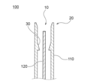
- the flavor inhaler 100 includes a housing 110 and a heater 120.
- the housing 110 has an opening 10 at one end and functions as a container for containing at least a portion of the consumable material 200 (FIG. 7A) inserted into the opening 10 through the opening 10 .
- the housing 110 is made of, for example, a resin, particularly PC (Polycarbonate), ABS (Acrylonitrile-Butadiene-Styrene) resin, PEEK (PolyEtherEtherKetone), a polymer alloy containing a plurality of types of polymers, or aluminum. It can be made of metal.
- the housing 110 is configured such that the cross-sectional area in the cross section perpendicular to the longitudinal direction of the housing 110 is the smallest in the vicinity of the opening 10 .
- the housing 110 has a shaping guide (guide portion) 20 and a restraining rib (biasing portion) 30 .
- the shaping guide 20 forms the opening 10 and deforms the cross-sectional shape of the consumable 200 inserted into the housing 110 so as to correspond to the shape of the heater 120 .
- the restraining ribs 30 are provided on the inner peripheral surface of the housing 110 and urge the consumable material 200 inserted into the housing 110 toward the heater 120 to deform the shape of the consumable material 200 .
- an air intake hole (not shown) is provided on the side opposite to the opening 10 of the housing 110.
- a bottom-flow type flavor inhaler 100 is configured by supplying air to the consumable material 200 inserted into the housing 110 through the air intake hole.
- the heater 120 is a flat PTC (Positive Temperature Coefficient) heater that is inserted into the consumable material 200 housed in the housing 110 and heats the consumable material 200 from the inside. Also, the heater 120 deforms the outer shape of the consumable material 200 inserted into the housing 110 along the shape of the heater 120 .
- PTC Physical Temperature Coefficient
- a PTC heater is a heater that uses a resistor that has a characteristic (PTC characteristic) that when it reaches a certain temperature (called the Curie temperature), the electrical resistance rises sharply and electricity stops flowing.
- PTC characteristic a characteristic that when it reaches a certain temperature
- the heater 120 may be a PTC heater using barium titanate (BaTiO3) having PTC characteristics as a resistor. In such a case, the heater 120 can set the Curie temperature of barium titanate to 350°C, so that the consumable material 200 can be heated at a suitable temperature below 350°C.
- FIG. 3 is a conceptual diagram schematically showing the heater 120 and the controller 900 that controls the heater 120.
- heater 120 is shown in a perspective view.
- the heater 120 includes a plurality of layers including at least a plurality of heating elements and first electrodes, as will be described later, but detailed illustration thereof is omitted in FIG.
- the flavor inhaler 100 has a controller 900 electrically connected to the heater 120 .
- the controller 900 includes a detector 910 and a heating controller 920 .
- a projection 125 is formed on one side of the heater 120 along the longitudinal direction.
- the heater 120 is inserted into the consumable 200 through the protrusion 125 . Therefore, the side of the heater 120 where the protrusion 125 is formed is the side closer to the outside when the consumable material 200 is housed in the housing 110, and is the downstream side of the air flow path during suction. From this point of view, in the following embodiments, the side on which the protrusion 125 is formed in the longitudinal direction of the heater 120 is called the downstream side, and the opposite side is called the upstream side.
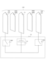
- FIG. 4 is an exploded view schematically showing the structure of the heater 120.
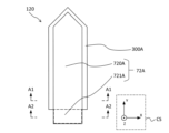
- FIG. FIG. 5A is a schematic plan view schematically showing the heater 120 viewed from the second electrode 72A side.
- FIG. 5B is a side view schematically showing the heater 120.
- FIG. 6A and 6B are diagrams schematically showing the A1-A1 cross section and the A2-A2 cross section of FIG. 5A, respectively.
- the heater 120 includes a plurality of heating elements 300A, 300B, a first electrode 71, and a plurality of second electrodes 72A, 72B.
- the second electrode 72A, the heating element 300A, the first electrode 71, the heating element 300B, and the second electrode 72B are stacked in this order, and the adjacent layers are electrically connected (see FIG. 5B).
- heating elements 300A and 300B will be referred to as heating element 300 when referring to each without distinction.
- second electrodes 72 When referring to each of the plurality of second electrodes 72A and 72B without distinction, they are referred to as second electrodes 72 .
- the heating element 300 extends longitudinally along the XY plane, with the Y axis being the longitudinal direction, the X axis being perpendicular to the Y axis, and the Z axis being perpendicular to the XY plane (coordinates System CS).
- the flavor inhaler 100 includes a circuit C1.
- Circuit C1 is electrically connected to first electrode 71, second electrode 72A and second electrode 72B.
- the circuit C1 is configured to apply a voltage between the first electrode 71 and the second electrode 72A and between the first electrode 71 and the second electrode 72B.
- the circuit C1 includes a DC power supply V1, a first switch SW1, and a second switch SW2.
- a DC power supply V1 is electrically connected to the first electrode 71 .
- the first switch SW1 is electrically connected to the DC power supply V1 and the second electrode 72A.
- the second switch SW2 is electrically connected to the DC power supply V2 and the second electrode 72B.
- the first switch SW1 and the second switch SW2 are arranged in parallel.
- the heating control section 920 controls the first switch SW1 and the second switch SW2, respectively, so that the heating of the heating element 300A and the heating of the heating element 300B can be independently controlled.
- a simple circuit configuration is shown in FIG. 4 for clarity, the form of the circuit C1 is not particularly limited as long as it can control the heating of the heating elements 300A and 300B.
- the heating element 300 is preferably a PTC element.
- the temperature of the PTC element rises to a predetermined temperature, it becomes difficult for current to flow due to the above-described PTC characteristics. Therefore, by using the PTC element as the heating element 300, it is possible to provide a safe flavor inhaler without the need for complicated control.
- the heating element 300 has a flat plate shape extending in the longitudinal direction.
- the shape of the heating element 300 is not particularly limited. However, if the heating element 300 is in the form of a flat plate, it is possible to form a compact structure by lamination, and voltage can be applied efficiently, which is preferable.
- the first electrode 71 includes a first electrode body 710 and a first connection electrode 711.
- the first connection electrode 711 is formed upstream of the first electrode body 710 .
- a connecting portion 712 to the circuit C ⁇ b>1 is formed on the end face on the upstream side of the first connecting electrode 711 .
- the second electrode 72A includes a second electrode body 720A and a second connection electrode 721A.
- the second connection electrode 721A is formed upstream of the second electrode body 720A.
- a connection portion 722A is formed on the upstream end surface of the second connection electrode 721A.
- the second electrode 72B includes a second electrode body 720B and a second connection electrode 721B.
- the second connection electrode 721B is formed upstream of the second electrode body 720B.
- a connection portion 722B with the circuit C1 is formed on the upstream end surface of the second connection electrode 721B.
- the first electrode 71 refers to an electrode placed between the plurality of heating elements 300 and electrically connected to each of the plurality of heating elements 300 .
- the heater 120 may have three or more heating elements 300 and two or more first electrodes 71 , and the first electrodes 71 may be arranged between the heating elements 300 facing each other. In this way, the heater 120 has a plurality of heating elements 300 stacked with at least one first electrode 71 interposed therebetween. This allows more flexible control of the heating of the tobacco portion 210 (FIG. 7A) using multiple heating elements 300 . Therefore, the release of flavor components from the flavor inhaler 100 can be controlled more flexibly.
- one first electrode 71 is used for heating a plurality of heating elements 300, it is possible to provide the heater 120, the flavor suction device 100, and the flavor suction system with a compact configuration, which can be efficiently used. can be manufactured to
- the heating element 300A is the first heating element and the heating element 300B is the second heating element
- the first heating element, the second heating element and the first electrode 71 are plate-shaped, and the first electrode 71 is sandwiched between the first heating element and the first heating element.
- a heating element and a second heating element are arranged to face each other.
- the plurality of heating elements 300 preferably include such first heating elements and second heating elements.
- the second electrode 72 refers to an electrode layered further outside the heating element 300 arranged on the outermost side among the plurality of heating elements 300 .
- heater 120 includes two heating elements 300, so both heating elements 300A and 300B correspond to the outermost heating elements 300.
- the first electrode 71 and the second electrode 72 have a plate-like shape extending in the longitudinal direction.
- the shapes of the first electrode 71 and the second electrode 72 are not particularly limited. However, if the first electrode 71 or the second electrode 72 is in the form of a flat plate, it is possible to form a compact structure by lamination, and voltage can be efficiently applied to the heating element 300, which is preferable.
- the material of the first electrode 71 and the second electrode 72 is not particularly limited as long as it has conductivity.
- the first electrode 71 and the second electrode 72 are preferably a conductive adhesive or a metal electrode from the viewpoint of facilitating processing of the heater 120 .
- the conductive adhesive for example, a so-called anisotropic conductive adhesive in which conductive particles are uniformly dispersed in an epoxy adhesive can be used.
- At least one of the first electrode 71 and the second electrode 72 preferably includes a flat support member having conductivity. As a result, malfunction and breakage of the heater 120 due to deformation can be suppressed.
- This support member preferably comprises stainless steel from the standpoint of rigidity and durability.
- a conductive or non-conductive plate-shaped support member may be arranged outside the second electrode 72 to support the heater 120 .
- the first electrode 71 preferably contains a heat insulating material.
- heat transfer between the plurality of heating elements 300 via the first electrodes 71 can be suppressed, and the temperature of each heating element 300 can be controlled more accurately. Also, the heat emitted from each heating element 300 can be efficiently directed toward the consumable 200 .
- heat insulating materials include silica aerogel and carbon aerogel.
- the first electrode 71 itself may have a porous structure.
- the second electrode body 720A, the heating element 300A, the first electrode body 710A, the heating element 300B and the second electrode body 720B are stacked in this order.
- the first connection electrode 711 and the second connection electrodes 721A, 721B are formed to protrude upstream along the longitudinal direction of the heater 120, and connection portions 712, 722A, and 722B are formed at the ends thereof.
- the first connection electrode 711 faces the second connection electrodes 721A and 721B via the gaps CL1 and CL2, respectively.
- connection electrode is preferably formed that protrudes in the longitudinal direction of the heating element 300 from the area in which the heating element 300 extends. This facilitates electrical connection with circuit C1 at connections 712, 722A and 722B.
- connection portions 712, 722A and 722B may be provided on surfaces connected to the end surfaces of the first connection electrode 711 and the second connection electrodes 721A and 721B, respectively, that is, surfaces along the longitudinal direction (Y-axis direction).
- lead wires can be connected to the surfaces near the end surfaces of the first connection electrode 711 and the second connection electrodes 721A and 721B.
- the surfaces of the first connection electrode 711 and the second connection electrodes 721A and 721B other than the connection portions 712, 722A and 722B are coated.
- a coating 610 is formed on the surface of the first connection electrode 711 .
- Coatings 620A and 620B are formed on the surfaces of the second connection electrodes 721A and 721B, respectively. This can prevent a short circuit in the direction perpendicular to the longitudinal direction (Y-axis direction) of the heating element 300 . From the viewpoint of suppressing short circuits, the first electrode body 710 and the second electrode bodies 720A and 720B may be coated.
- electrodes other than the first connection electrode 711 and the second connection electrodes 721A, 721B namely the first electrode body 710 and the second electrode bodies 720A, 720B are connected to the adjacent heating element 300. does not protrude from the extending range of the heating element 300 along the extending plane (XY plane).
- the second electrode body 720A is formed in the range of the XY plane where the adjacent heating element 300A extends, and does not protrude from the range in top view.
- control unit 900 includes a processing device such as a PCB (Printed Circuit Board).
- This processing device is composed of a CPU, a memory, and the like, and controls the operation of the flavor inhaler 100 .
- the detection unit 910 detects the start of suction.
- a detection unit 910 detects a user's operation on an input device such as a push button or a slide switch (not shown). Alternatively, the detection unit 910 detects a user's puffing action. After these detections, the detection unit 910 performs processing so that the heating control unit 920 starts applying voltage for heating.
- the heating control unit 920 electrically controls the heating of the heating elements 300A and 300B by electrically controlling the first electrode 71, the second electrode 72A and the second electrode 72B.
- the heating control unit 920 is configured to be able to independently control the voltage applied to the heating element 300A or the current flowing through the heating element 300A and the voltage applied to the heating element 300B or the current flowing through the heating element 300B. is preferred.
- the heating control section 920 is configured to be able to control the heating of the heating element 300A and the heating of the heating element 300B independently of each other.
- the heating control section 920 electrically controls the first electrode 71, the second electrode 72A, and the second electrode 72B so as to heat the heating element 300B after heating the heating element 300A.
- the heating control section 920 electrically controls the first electrode 71, the second electrode 72A, and the second electrode 72B so as to heat the heating element 300B after heating the heating element 300A.
- the heating control unit 920 heats the heating element 300A when the detection unit 910 performs processing indicating that the start of suctioning has been detected.
- the heating control unit 920 starts heating the heating element 300B when the switching condition is satisfied.
- the switching condition is that a predetermined time has elapsed since the heating of the heating element 300A was started, or that the user has input via an input device (not shown).
- a button may be arranged on the flavor inhaler 100, and when the user presses the button, the heating control section 920 may start heating the heating element 300B. Whether or not the heating of the heating element 300A is stopped when the heating of the heating element 300B is started is not particularly limited.
- the heating control unit 920 terminates heating when the termination condition is satisfied.
- the end condition is that a predetermined time has passed since the start of heating, or that the number of puffing actions by the user has exceeded a certain value.
- the control by the heating control unit 920 is not particularly limited to the above example, and can be appropriately set according to the desired heating mode.
- heating element 300B may be heated first, followed by heating element 300A.
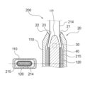
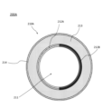
- FIG. 7A is a schematic side sectional view showing the consumable product 200 according to this embodiment.
- 7B is a cross-sectional view showing a section of the tobacco portion 210 perpendicular to the longitudinal direction of the consumable product 200 shown in FIG. 7A.
- the consumable product 200 has a tobacco portion (non-insertion portion) 210 and a paper tube 220 .
- the tobacco portion 210 has a through hole 211 in the center into which the heater 120 is inserted.
- the tobacco portion 210 has a two-layer structure of a flavor release layer (annular sheet) 212 and an elastically deformable layer (annular sheet) 213 arranged so as to surround the inserted heater 120 .
- a wrapper 214 is wound around the outer periphery of the elastic deformation layer 213 .
- the flavor-releasing layer 212 is composed of, for example, a tobacco sheet and a non-tobacco sheet carrying glycerin around the tobacco sheet, and is heated by the heater 120 to release flavor-containing volatile compounds. It should be noted that the flavor release layer 212 can include only one of tobacco sheets and non-tobacco sheets.
- the elastic deformation layer 213 is made of, for example, a non-woven fabric sheet, a corrugated sheet, a non-tobacco sheet, or the like, and is elastically deformable in its thickness direction (that is, the radial direction of the cylindrical elastic deformation layer 213). The elastic deformation layer 213 contributes to the deformation of the consumable material 200 along the shape of the heater 120 when the heater 120 is inserted.
- the elastic deformation layer 213 is elastically deformed in the thickness direction with respect to the heater 120 , making it easier to contact or approach the heater 120 . Therefore, the flavor release layer 212 can be brought into contact with or closer to the heater 120, and the consumable material 200 can be efficiently heated.
- the paper tube 220 cools the volatile compounds released from the flavor release layer 212.
- Tobacco portion 210 includes flavor release layer 212 and elastically deformable layer 213 arranged to surround heater 120 to be inserted, so that heater 120 is inserted into consumable material 200 to change the shape of consumable material 200. It can be easily transformed.
- the cross-sectional shape of the consumable material 200 may be circular or elliptical.
- the non-tobacco sheet may contain a flavor generating base material.
- the flavor-generating base material is a material that imparts flavor and taste, and is preferably a tobacco material.
- Flavor-generating substrates may also include perfumes.
- a flavoring agent is a substance that provides an odor or flavor.
- the perfume may be a natural perfume or a synthetic perfume.
- the perfume one kind of perfume may be used, or a mixture of multiple kinds of perfumes may be used.
- the fragrance for example, any fragrance such as essential oil, natural fragrance, synthetic fragrance, etc. can be used as long as it is a fragrance that is usually used.
- it may be liquid or solid, and its properties are not limited.
- the flavor generating substrate may also include cooling agents or flavorants.
- the tobacco sheet may contain, for example, tobacco, polyhydric alcohol, and the like.
- Polyhydric alcohols may be used alone or in combination of two or more in the tobacco sheet.
- the polyhydric alcohol may also be added to the elastic deformation layer 213 described above.
- Tobacco sheets can be formed into sheets by mixing powdered tobacco and polyhydric alcohol with a binder.
- Describe relationships. 8 to 10 are cross-sectional views showing how the consumable material 200 is accommodated in the flavor inhaler 100.
- the consumable material 200 is applied to the flavor inhaler 100 to configure the flavor inhaling system.
- 8 to 10 show the flavor release layer 212 and the elastically deformable layer 213 of the consumable product 200 as one annular sheet 215.
- FIG. 8 to 10 show the flavor release layer 212 and the elastically deformable layer 213 of the consumable product 200 as one annular sheet 215.
- FIG. 8 shows a state in which the consumable material 200 passes through the shaping guide 20 with respect to a cross section in the width direction of the heater 120 and a cross section perpendicular to the longitudinal direction of the housing 110 at the entrance portion 22 of the shaping guide 20 .
- FIG. 9 shows a state in which the consumable material 200 passes through the restraining ribs 30, showing a cross section in the width direction of the heater 120, and perpendicular to the longitudinal direction of the housing 110 at the intermediate portion and the other end of the restraining ribs 30. It shows the cross section to be done.
- FIG. 9 shows a state in which the consumable material 200 passes through the restraining ribs 30, showing a cross section in the width direction of the heater 120, and perpendicular to the longitudinal direction of the housing 110 at the intermediate portion and the other end of the restraining ribs 30. It shows the cross section to be done.
- FIG. 10 shows a state in which the consumable material 200 is accommodated in a predetermined accommodation position of the housing 110, in a cross section in the width direction of the heater 120 and in the longitudinal direction of the housing 110 near the other end of the heater 120. An orthogonal cross section is shown.
- the shaping guide 20 has a tapered portion 21, an entrance portion 22, and a contact portion 23.
- the tapered portion 21 is configured to expand toward one end of the housing 110 and guides the insertion of the consumable material 200 into the flavor inhaler 100 .
- the entrance part 22 is provided at the end of the housing 110 and has an elliptical cross-section, and has a long axis equal to or larger than the long axis of the consumable material 200 after being housed in the housing 110 and a short axis of being housed in the housing 110 . It is configured to be approximately the same length as the diameter of the consumable 200 prior to insertion.
- the contact portion 23 is provided on the inner peripheral surface of the housing 110 and has an elliptical cross section, and is configured such that the minimum inner peripheral length is approximately equal to the outer peripheral length of the consumable product 200 .
- the heater 120 has a projecting portion 125 with a sharp end. Therefore, the heater 120 can be easily inserted into the consumable item 200 .
- Heater 120 is configured such that its width increases toward the other end. Accordingly, as the consumable product 200 is inserted through the shaping guide 20 , the contour of the consumable product 200 is deformed along the shape of the heater 120 . Specifically, the consumable material 200 is spread in the width direction of the heater 120 . As a result, the consumable material 200 can be brought into close contact with the heater 120, and the heat transfer efficiency from the heater 120 to the consumable material 200 can be improved. In addition, since the heater 120 spreads the consumable material 200, it is possible to prevent the consumable material 200 from falling off.
- the heater 120 has a flat plate shape, and deforms the outer shape of the consumable material 200 inserted into the housing 110 into an elliptical cross-sectional shape.
- the major axis of the consumable material 200 after being housed in the housing 110 is longer than the diameter of the consumable material 200 before being housed in the housing 110, and the diameter of the consumable material 200 after being housed in the housing 110.
- the short diameter is shorter than the diameter of the consumable item 200 before being housed in the housing 110 .
- the heater 120 deforms the outer shape of the consumable material 200 to be inserted into the housing 110 into an elliptical cross-sectional shape, thereby shortening the width of the housing 110 occupied by the consumable material 200 .
- the housing 110 can be made thinner. Further, the contact area between the heater 120 and the consumable item 200 can be increased by deforming the outer shape of the consumable item 200 inserted into the housing 110 into an elliptical cross-sectional shape. Therefore, heat transfer efficiency from the heater 120 to the consumable material 200 can be improved.
- an air layer 40 is formed over the entire circumference of the consumable item 200 between the consumable item 200 and the housing 110. be done. Since the air layer 40 has a low thermal conductivity, it can insulate the space between the consumable material 200 and the housing 110 and reduce the energy required for heating the consumable material 200 . Further, the inlet portion 22 is in contact with the consumable material 200 over the entire circumference of the consumable material 200 and seals the air layer 40 . This suppresses air convection in the air layer 40 .
- FIG. 11 is a flow chart showing the flow of the flavor releasing method according to this embodiment.
- This release method is performed by the control unit 900 .
- This release method provides flexible control over the release of flavoring components by independently heating and controlling heating elements 300A and 300B. In addition, by heating a portion of the plurality of heating elements 300 at the start of suction, the time until the flavor is generated can be shortened.
- step S101 the detection unit 910 detects the start of suction by the user.
- step S102 is performed.
- step S ⁇ b>102 the heating control section 920 heats some of the heating elements 300 ⁇ /b>A among the plurality of heating elements 300 .
- step S103 is performed.
- step S103 the heating control unit 920 determines whether or not the switching condition is satisfied. If the switching condition is satisfied, an affirmative determination is made in step S103, and step SS104 is performed. If the switching condition is not satisfied, a negative determination is made in step S103, and step S103 is repeated.
- step S104 the heating control section 920 heats at least some of the heating elements 300B other than the heating elements 300A. After step S104, step S105 is performed.
- step S105 the heating control unit 920 determines whether or not the termination condition is satisfied. If the termination condition is satisfied, an affirmative determination is made in step S105, and step SS106 is performed. If the termination condition is not satisfied, a negative determination is made in step S105, and step S105 is repeated.
- step S106 the heating control unit 920 ends heating. After step S106 ends, the process ends.
- the heating control unit 920 heats some of the heating elements 300A of the plurality of heating elements 300, and then heats at least some of the other heating elements 300B. Heater 120 is controlled to heat. As a result, the time until the user can inhale the flavor can be shortened.
- the consumable may comprise multiple flavor release layers each having a flavor ingredient.
- FIG. 12 is a conceptual diagram showing a cross section of the tobacco portion perpendicular to the longitudinal direction of the consumable product according to this modified example.
- the consumable item 200A differs from the consumable item 200 of the above-described embodiment in that it includes a tobacco portion 210A instead of the tobacco portion 210 (FIG. 7A) described above.
- the tobacco portion 210A includes a first flavor release layer 212A and a second flavor release layer 212B.
- the first flavor release layer 212A and the second flavor release layer 212B are arranged on both sides of the through hole 211 into which the heater 120 is inserted.
- the first flavor release layer 212A and the second flavor release layer 212B are placed in contact with heating element 300A and heating element 300B, respectively (or heating element 300B and heating element 300A, respectively) when consumable 200A is contained in housing 110. They can be arranged in opposite positions.
- the first flavor emitting layer 212A may be heated by some heating elements 300 of the plurality of heating elements 300 and the second flavor emitting layer 212B may be heated by other heating elements 300.
- the consumable 200A is arranged such that the first flavor release layer 212A and the second flavor release layer 212B are positioned to face their respective heating elements 300 when the consumable 200A is accommodated in the housing 110. , marks for positioning, etc. are preferably attached.
- the first flavor release layer 212A and the second flavor release layer 212B preferably contain different flavor components from the viewpoint of providing a flavor suction system capable of changing the flavor.
- the flavor components disposed in the first flavor release layer 212A and the second flavor release layer 212B are not particularly limited, and the first flavor release layer 212A and the second flavor release layer 212B may contain the same flavor component.
- Tobacco portion 210A may include a flavor release layer containing three or more of the same or different flavor components.
- the consumable product 200A includes a first flavor release layer 212A and a second flavor release layer 212B, which are multiple portions having the same or different flavor components.
- the first flavor release layer 212A and the second flavor release layer 212B are configured to be positioned to face each of the plurality of heating elements 300 during inhalation. This allows for more flexibility in controlling the release of flavoring ingredients from the flavor suction system.
- flavor components can be arranged in the plurality of portions according to user's preference or convenience.
- the first electrode may include multiple energized regions that heat different portions of the heating element.
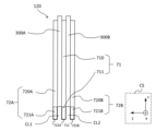
- FIG. 13A is a side view schematically showing the heater 120A of this modified example.
- FIG. 13B is a cross-sectional view taken along line BB of FIG. 13A.
- the heater 120A differs from the heater 120 of the above-described embodiment in that it includes a first electrode 71A instead of the first electrode 71 described above.
- the first electrode 71A includes a plurality of conducting regions 400 and a plurality of connecting regions 411 and 421.
- the plurality of conducting regions 400 includes downstream regions 410 and upstream regions 420 .
- Downstream region 410 is formed downstream of upstream region 420 .
- a portion facing the downstream region 410 is called a first heating section 310, and a portion facing the upstream region 420 is called a second heating section 320.
- a first heating section and a second heating section are similarly set for the heating element 300A, but the description is omitted.
- the first heating section 310 extends along the normal direction of the plane (XY plane) on which the flat heating element 300B extends (hereinafter simply referred to as the normal direction, which corresponds to the Z-axis direction). 410 and the second electrode body 720B.
- the first heating section 310 contacts and is electrically connected to the downstream region 410 and the second electrode body 720B.
- the first heating section 310 is heated by current generated by the voltage applied between the downstream region 410 and the second electrode 72B.
- the second heating section 320 is a region sandwiched between the upstream region 420 and the second electrode body 720A along the normal direction.
- the second heating section 320 contacts and is electrically connected to the upstream region 420 and the second electrode body 720B.
- the second heating section 320 is heated by current generated by the voltage applied between the upstream region 420 and the second electrode 72B.
- the downstream region 410 has a pentagonal flat plate shape when viewed from the top
- the upstream region 420 has a rectangular flat plate shape when viewed from the top.
- the shape and size of the downstream region 410 and the upstream region 420 are not particularly limited as long as the downstream region 410 and the upstream region 420 can be arranged to face different portions of the adjacent heating elements 300. .
- the downstream area 410 is electrically connected to the control section 900 via the connection area 411 .
- the connection region 411 is arranged along the longitudinal direction of the heating element 300 upstream of the downstream region 410 .
- the connection region 411 has a first end electrically connected to the downstream region 410 and a second end connected to a conductor outside the heater 120A via a connection portion 411C.
- 411 C of connection parts are end surfaces of the upstream of the connection area
- the upstream area 420 is electrically connected to the control section 900 via the connection area 421 .
- the connecting region 421 is arranged longitudinally upstream of the upstream region 420 .
- connection region 421 has a first end electrically connected to the upstream region 420 and a second end connected to a conductor outside the heater 120A via a connection portion 421C.
- 421 C of connection parts are end surfaces of the upstream of the connection area
- a non-conducting region 415 is arranged between the downstream region 410 and the connection region 411 and the upstream region 420 and the connection region 421 from the viewpoint of preventing a short circuit.
- the surfaces of the connection regions 411 and 421 other than the connection portions 411C and 421C are insulated by coating (not shown).
- the coating of this surface and the material of the non-conducting region 415 are not particularly limited, and can be, for example, glass coating.
- the electrodes other than the connection regions 411 and 421 do not protrude from the extending range of the heating element 300 along the extending surface (XY plane) of the flat heating element 300 . If there is an electrode protruding from this range, it will cause a short circuit, so this is to be suppressed.
- the material of the conducting region 400 and the connection regions 411 and 421 is not particularly limited as long as it has conductivity.
- the conducting region 400 and connecting regions 411, 421 preferably comprise metal or conductive adhesive.
- the heating control section 920 can electrically control the downstream region 410, the upstream region 420, the second electrode 72A and the second electrode 72B independently. Therefore, the heating of the first heating section 310 and the second heating section 320 of the heating element 300B, and the heating of the first heating section and the second heating section set for the heating element 300A as well as for the heating element 300B, are independently performed. It is possible to control
- the heating control unit 920 preferably heats the first heating section 310 arranged on the most downstream side.
- the aerosol heated and emitted by the first heating section 310 arranged on the downstream side has a short distance to the paper tube 220, so it is less likely to be blocked by other portions of the tobacco portion 210. Therefore, it is possible to suppress a decrease in the amount of aerosol inhaled by the user immediately after the start of inhalation.
- the first heating section 310 need not be configured to be heated first.
- the positions and number of the plurality of current-carrying regions 400 are not particularly limited, either, and can be appropriately set according to the mode of heating control.
- a plurality of conducting regions 400 may be arranged in a direction (Z-axis direction) perpendicular to the air flow path.
- the second electrode 72A or 72B may also be provided with a plurality of current-carrying regions similar to the current-carrying region 400 described above.
- the conducting regions 400 facing each other with one heating element 300 therebetween preferably have the same size and shape.
- one current-carrying region 400 has a shape and size based on the current-carrying regions 400 that face each other with the heating element 300 interposed therebetween. This allows for more precise control of the temperature of the heating section between these energized regions 400 .
- one or more of the first electrode 71A and the second electrode 72 includes a plurality of conducting regions 400.
- each of the plurality of current-carrying regions 400 is connected to the first heating section 310 and the second heating section 320, which are the plurality of heating portions of the heating element 300B adjacent to the first electrode 71A. They are arranged facing each other. As a result, the heating of each of these heating portions of the heating element 300 can be controlled, so that the heating by the heater 120A can be controlled more flexibly.
Abstract
This flavor inhaler (100) comprises a heater (120, 120A) that is formed by stacking a plurality of heating elements (300, 300A, 300B) with at least one first electrode (71, 71A) therebetween.
Description
本発明は、香味吸引器および香味吸引システムに関する。
The present invention relates to a flavor suction device and a flavor suction system.
従来、材料の燃焼をすることなく香味を吸引するための香味吸引器が知られている。このような香味吸引器に使用される様々なヒータが提案されている(特許文献1参照)。このようなヒータにおいて、加熱素子および導線が積層されているものが提案されている(特許文献2参照)。
Conventionally, flavor inhalers for inhaling flavor without burning materials have been known. Various heaters for use in such flavor inhalers have been proposed (see Patent Document 1). As such a heater, a heater in which a heating element and a conductive wire are laminated has been proposed (see Patent Document 2).
本発明の目的の1つは、より柔軟に加熱を制御できるヒータを備える香味吸引器および香味吸引システムを提供することである。
One of the objects of the present invention is to provide a flavor inhaler and a flavor inhaling system equipped with a heater that can control heating more flexibly.
第1態様によれば、香味吸引器が提供される。この香味吸引器は、複数の加熱素子が少なくとも一つの第1電極を介して積層されているヒータを備える。
According to the first aspect, a flavor inhaler is provided. This flavor inhaler comprises a heater in which a plurality of heating elements are stacked via at least one first electrode.
第1態様によれば、複数の加熱素子を利用してより柔軟に加熱を制御することができる。したがって、より柔軟に香味吸引器からの香味成分の放出を制御できる。
According to the first aspect, heating can be more flexibly controlled using a plurality of heating elements. Therefore, the release of flavor components from the flavor inhaler can be controlled more flexibly.
第2態様は、第1態様において、前記複数の加熱素子は、第1加熱素子および第2加熱素子を含み、前記第1加熱素子、第2加熱素子および前記第1電極は、平板状であり、前記第1電極を挟んで前記第1加熱素子および前記第2加熱素子が対向して配置されている、ことを要旨とする。
A second aspect is the first aspect, wherein the plurality of heating elements includes a first heating element and a second heating element, and the first heating element, the second heating element, and the first electrode are plate-shaped. , wherein the first heating element and the second heating element are arranged to face each other with the first electrode interposed therebetween.
第2態様によれば、第1加熱素子、第1電極および第2加熱素子がこの順で積層した平板状のヒータを提供することができるため、コンパクトな構成を実現し、効率的に電圧を印加することができる。
According to the second aspect, it is possible to provide a flat heater in which the first heating element, the first electrode, and the second heating element are laminated in this order. can be applied.
第3態様は、第1態様または第2態様において、前記複数の加熱素子のうち最も外側に配置されている加熱素子の外側に積層された第2電極を備え、前記第1電極および前記第2電極の少なくとも一つは、導電性を有する平板状の支持部材を含む、ことを要旨とする。
A third aspect is the first aspect or the second aspect, further comprising a second electrode laminated outside the outermost heating element among the plurality of heating elements, wherein the first electrode and the second The gist of the invention is that at least one of the electrodes includes a flat support member having conductivity.
第3態様によれば、第1電極または第2電極によりヒータを支持することができるため、変形によるヒータの不具合及び破壊を抑制することができる。また、第1電極または第2電極が支持体を兼ねるため、コンパクトな構成のヒータおよび香味吸引器を提供することができ、さらに香味吸引器を効率的に製造することができる。
According to the third aspect, since the heater can be supported by the first electrode or the second electrode, malfunction and breakage of the heater due to deformation can be suppressed. In addition, since the first electrode or the second electrode also serves as a support, it is possible to provide a compact heater and flavor inhaler, and to efficiently manufacture the flavor inhaler.
第4態様は、第3態様において、前記支持部材は、ステンレス鋼を含む、ことを要旨とする。
A gist of a fourth aspect is that in the third aspect, the support member includes stainless steel.
第4態様によれば、ステンレス鋼は剛性および耐久性に優れるため、変形によるヒータの不具合及び破壊をさらに抑制することができる。
According to the fourth aspect, since stainless steel is excellent in rigidity and durability, it is possible to further suppress defects and breakage of the heater due to deformation.
第5態様は、第3態様または第4態様において、前記第1電極および前記第2電極のうち少なくとも一つの電極には、前記少なくとも1つの電極に隣接する隣接加熱素子の延在する面に沿って、前記隣接加熱素子が延在する範囲から前記隣接加熱素子の長手方向に突出する接続電極が形成されている、ことを要旨とする。
A fifth aspect is that in the third aspect or the fourth aspect, at least one electrode of the first electrode and the second electrode has a heating element extending along a surface of an adjacent heating element adjacent to the at least one electrode. A connection electrode is formed to protrude in the longitudinal direction of the adjacent heating element from a range in which the adjacent heating element extends.
第5態様によれば、接続電極とヒータ外部の回路との電気的接続をしやすくなる。
According to the fifth aspect, it becomes easier to electrically connect the connection electrode and the circuit outside the heater.
第6態様は、第5態様において、前記接続電極はその端面または前記端面の近傍に外部との接続部を有し、前記接続部以外の表面は絶縁処理されている、ことを要旨とする。
A gist of a sixth aspect is that, in the fifth aspect, the connection electrode has a connection portion with the outside at or in the vicinity of the end surface, and the surface other than the connection portion is insulated.
第6態様によれば、接続電極間、および接続電極と他の電極との短絡を抑制することができる。
According to the sixth aspect, short circuits between connection electrodes and between connection electrodes and other electrodes can be suppressed.
第7態様は、第5態様または第6態様において、前記接続電極以外の電極は、前記隣接加熱素子が延在する面に沿って、前記隣接加熱素子が延在する範囲から突出しない、ことを要旨とする。
A seventh aspect is the fifth aspect or the sixth aspect, wherein electrodes other than the connection electrodes do not protrude from the range in which the adjacent heating elements extend along the surface along which the adjacent heating elements extend. This is the gist.
第7態様によれば、接続電極以外の電極と他の電極との短絡を抑制することができる。
According to the seventh aspect, it is possible to suppress short circuits between electrodes other than the connection electrode and other electrodes.
第8態様は、第3態様から第7態様において、前記第1電極および前記第2電極のうち1以上の電極は、複数の通電領域を含み、前記複数の通電領域のそれぞれは、前記1以上の電極に隣接する加熱素子の複数の加熱部分に対向して配置されている、ことを要旨とする。
An eighth aspect is the third aspect to the seventh aspect, wherein one or more electrodes of the first electrode and the second electrode include a plurality of current-carrying regions, and each of the plurality of current-carrying regions includes the one or more and positioned opposite a plurality of heating portions of the heating element adjacent to the electrode of the heating element.
第8態様によれば、加熱素子の複数の加熱部分のそれぞれの加熱を制御することができるため、より一層柔軟にヒータによる加熱を制御することができる。
According to the eighth aspect, since the heating of each of the plurality of heating portions of the heating element can be controlled, the heating by the heater can be controlled more flexibly.
第9態様は、第1態様から第8態様において、前記第1電極は、断熱材料を含む、ことを要旨とする。
The gist of a ninth aspect is that, in any one of the first to eighth aspects, the first electrode includes a heat insulating material.
第9態様によれば、複数の加熱素子の間の熱伝達を抑制し、各加熱素子の温度をより正確に制御することができる。また加熱素子から発せられる熱を消費材の方向へ効率的に指向させることができる。
According to the ninth aspect, heat transfer between the plurality of heating elements can be suppressed, and the temperature of each heating element can be controlled more accurately. Also, the heat emitted from the heating element can be efficiently directed toward the consumable.
第10態様は、第1態様から第9態様において、前記複数の加熱素子のそれぞれに印加される電圧または電流を制御する加熱制御部をさらに備える、ことを要旨とする。
A gist of a tenth aspect is that, in any one of the first to ninth aspects, a heating control section is further provided for controlling the voltage or current applied to each of the plurality of heating elements.
第10態様によれば、複数の加熱素子をさらに柔軟に制御することができる。
According to the tenth aspect, the plurality of heating elements can be controlled more flexibly.
第11態様は、第10態様において、前記加熱制御部は、前記複数の加熱素子のうち一部の加熱素子を加熱した後、他の少なくとも一部の加熱素子を加熱するように、前記電圧を制御する、ことを要旨とする。
In an eleventh aspect based on the tenth aspect, the heating control unit heats some of the plurality of heating elements, and then applies the voltage so as to heat at least some other heating elements. The gist is to control.
第11態様によれば、先に加熱された加熱素子により加熱される香味発生基材の温度が速く上昇する。これにより、香味吸引器を起動してから香味吸引器のユーザ(以下、単にユーザと呼ぶ)が香味を吸引できるまでの時間を短くすることができる。
According to the eleventh aspect, the temperature of the flavor-generating base heated by the previously heated heating element rises quickly. As a result, the time from when the flavor inhaler is activated until the user of the flavor inhaler (hereinafter simply referred to as the user) can inhale the flavor can be shortened.
第12態様は、第1態様から第11態様において、前記複数の加熱素子は、PTC素子を含む、ことを要旨とする。
The gist of the twelfth aspect is that in the first to eleventh aspects, the plurality of heating elements include PTC elements.
第12態様によれば、PTC素子の特性により、所定の温度まで上昇すると電流が流れにくくなるため、複雑な制御の必要がなく、安全な香味吸引器を提供することができる。
According to the twelfth aspect, due to the characteristics of the PTC element, it becomes difficult for current to flow when the temperature rises to a predetermined temperature.
第13態様によれば、香味吸引システムが提供される。この香味吸引システムは、香味成分を有する消費材と、第1態様から第12態様のいずれかの香味吸引器と、を備える。
According to the thirteenth aspect, a flavor suction system is provided. This flavor inhalation system comprises a consumable having a flavor component and the flavor inhaler of any one of the first to twelfth aspects.
第13態様によれば、複数の加熱素子を利用してより柔軟に加熱を制御することができる。したがって、より柔軟に香味吸引システムからの香味成分の放出を制御できる。
According to the thirteenth aspect, heating can be more flexibly controlled using a plurality of heating elements. Therefore, the release of flavor components from the flavor suction system can be controlled more flexibly.
第14態様は、第13態様において、前記消費材は、吸引の際に前記複数の加熱素子のそれぞれに対向する位置に配置されるように構成された、同一または異なる香味成分を有する複数の部分を備える、ことを要旨とする。
A fourteenth aspect is the thirteenth aspect, wherein the consumable material has a plurality of portions having the same or different flavor components, which are arranged to face each of the plurality of heating elements during suction. The gist is that
第14態様によれば、香味成分の放出をさらに柔軟に制御することができる。また、ユーザの好みまたは利便性等に応じて複数の部分に香味成分を配置することができる。
According to the fourteenth aspect, the release of flavor components can be controlled more flexibly. In addition, flavor components can be arranged in a plurality of portions according to user's preference or convenience.
以下、本発明の実施形態について図面を参照して説明する。以下で説明する図面において、同一のまたは相当する構成要素には、同一の符号を付して重複した説明を省略する。なお、以下の実施形態では、消費材としてたばこスティックを例に挙げて説明するが、加熱により香味を発生するものであれば、消費材はたばこに限定されない。
Hereinafter, embodiments of the present invention will be described with reference to the drawings. In the drawings described below, the same or corresponding components are denoted by the same reference numerals, and duplicate descriptions are omitted. In the following embodiments, tobacco sticks are taken as an example of the consumable material, but the consumable material is not limited to tobacco as long as it generates flavor when heated.
図1は、本発明の一実施形態に係る香味吸引器100の要部をヒータ120の幅方向について示す断面図である。図2は、香味吸引器100の要部をヒータ120の厚み方向について示す断面図である。
FIG. 1 is a cross-sectional view showing the main part of the flavor inhaler 100 according to one embodiment of the present invention in the width direction of the heater 120. FIG. FIG. 2 is a cross-sectional view showing the main part of the flavor inhaler 100 in the thickness direction of the heater 120. As shown in FIG.
図1および図2に示すように、香味吸引器100は、筐体110とヒータ120とを備える。筐体110は、一端に開口10を有し、開口10を介して、開口10に挿入される消費材200(図7A)の少なくとも一部を収容する収容部として機能する。筐体110は、例えば、樹脂製であり、特に、PC(Polycarbonate)、ABS(Acrylonitrile-Butadiene-Styrene)樹脂、PEEK(PolyEtherEtherKetone)または複数種類のポリマーを含有するポリマーアロイ等、あるいは、アルミ等の金属で形成され得る。ここで、筐体110は、筐体110の長手方向に直交する断面における断面積が、開口10近傍において最も小さくなるように構成されている。
As shown in FIGS. 1 and 2, the flavor inhaler 100 includes a housing 110 and a heater 120. The housing 110 has an opening 10 at one end and functions as a container for containing at least a portion of the consumable material 200 (FIG. 7A) inserted into the opening 10 through the opening 10 . The housing 110 is made of, for example, a resin, particularly PC (Polycarbonate), ABS (Acrylonitrile-Butadiene-Styrene) resin, PEEK (PolyEtherEtherKetone), a polymer alloy containing a plurality of types of polymers, or aluminum. It can be made of metal. Here, the housing 110 is configured such that the cross-sectional area in the cross section perpendicular to the longitudinal direction of the housing 110 is the smallest in the vicinity of the opening 10 .
また、筐体110は、整形ガイド(ガイド部)20と抑えリブ(付勢部)30とを有する。整形ガイド20は、開口10を形成し、筐体110に挿入される消費材200の断面形状を、ヒータ120の形状に対応するよう変形させる。抑えリブ30は、筐体110の内周面に設けられ、筐体110に挿入される消費材200をヒータ120に向けて付勢し、消費材200の形状を変形させる。
Further, the housing 110 has a shaping guide (guide portion) 20 and a restraining rib (biasing portion) 30 . The shaping guide 20 forms the opening 10 and deforms the cross-sectional shape of the consumable 200 inserted into the housing 110 so as to correspond to the shape of the heater 120 . The restraining ribs 30 are provided on the inner peripheral surface of the housing 110 and urge the consumable material 200 inserted into the housing 110 toward the heater 120 to deform the shape of the consumable material 200 .
また、筐体110の開口10とは反対側、すなわち筐体110の底部には、図示しない吸気孔が設けられる。この吸気孔を介して筐体110に挿入される消費材200に空気が供給されることで、ボトムフロー型の香味吸引器100が構成される。筐体110の開口10とは反対側に吸気孔を設けることにより、筐体110の開口10近傍の構成を簡素化することができる。なお、所望の精度でヒータ120に対して消費材200を固定することができれば、筐体110の形状は特に限定されず、例えば整形ガイド20および抑えリブ30を設けなくともよい。
Also, on the side opposite to the opening 10 of the housing 110, that is, on the bottom of the housing 110, an air intake hole (not shown) is provided. A bottom-flow type flavor inhaler 100 is configured by supplying air to the consumable material 200 inserted into the housing 110 through the air intake hole. By providing an air intake hole on the side opposite to the opening 10 of the housing 110, the configuration of the vicinity of the opening 10 of the housing 110 can be simplified. The shape of the housing 110 is not particularly limited as long as the consumable material 200 can be fixed to the heater 120 with desired accuracy.
ヒータ120は、筐体110に収容された消費材200に挿入され、消費材200を内部から加熱する平板状のPTC(Positive Temperature Coefficient)ヒータである。また、ヒータ120は、筐体110に挿入される消費材200の外形を、ヒータ120の形状に沿って変形させる。
The heater 120 is a flat PTC (Positive Temperature Coefficient) heater that is inserted into the consumable material 200 housed in the housing 110 and heats the consumable material 200 from the inside. Also, the heater 120 deforms the outer shape of the consumable material 200 inserted into the housing 110 along the shape of the heater 120 .
PTCヒータは、ある温度(キュリー温度と称される)になると電気抵抗が急激に上昇し、電気が流れなくなる特性(PTC特性)を有する抵抗体を用いたヒータである。PTCヒータは、PTC特性を活用することで、所定の温度以上になると加熱を停止する制御装置等の必要なく温度を一定温度以下に保つことが可能である。ヒータ120は、PTC特性を有するチタン酸バリウム(BaTiO3)を抵抗体とするPTCヒータであってもよい。このような場合、ヒータ120は、チタン酸バリウムのキュリー温度を350℃に設定することができるため、350℃未満の好適な温度で消費材200を加熱することができる。
A PTC heater is a heater that uses a resistor that has a characteristic (PTC characteristic) that when it reaches a certain temperature (called the Curie temperature), the electrical resistance rises sharply and electricity stops flowing. By utilizing the PTC characteristics, the PTC heater can keep the temperature below a certain temperature without the need for a control device or the like that stops heating when the temperature reaches a predetermined temperature or higher. The heater 120 may be a PTC heater using barium titanate (BaTiO3) having PTC characteristics as a resistor. In such a case, the heater 120 can set the Curie temperature of barium titanate to 350°C, so that the consumable material 200 can be heated at a suitable temperature below 350°C.
図3は、ヒータ120とヒータ120を制御する制御部900を模式的に示す概念図である。図3では、ヒータ120は斜視図により示されている。ヒータ120は、後述するように、複数の加熱素子および第1電極を少なくとも含む複数の層を備えるが、図3では詳細の図示は省略している。香味吸引器100は、ヒータ120と電気的に接続された制御部900を備える。制御部900は、検知部910と、加熱制御部920とを備える。
FIG. 3 is a conceptual diagram schematically showing the heater 120 and the controller 900 that controls the heater 120. FIG. In FIG. 3, heater 120 is shown in a perspective view. The heater 120 includes a plurality of layers including at least a plurality of heating elements and first electrodes, as will be described later, but detailed illustration thereof is omitted in FIG. The flavor inhaler 100 has a controller 900 electrically connected to the heater 120 . The controller 900 includes a detector 910 and a heating controller 920 .
ヒータ120は、長手方向に沿って一方の側に突起部125が形成されている。ヒータ120は、突起部125から消費材200に挿入される。したがって、ヒータ120において突起部125が形成されている側が、消費材200が筐体110に収容された際に外部に近い側となり、吸引の際の空気の流路の下流側となる。この観点から、以下の実施形態では、ヒータ120の長手方向において突起部125が形成された側を下流側、その反対側を上流側と呼ぶ。
A projection 125 is formed on one side of the heater 120 along the longitudinal direction. The heater 120 is inserted into the consumable 200 through the protrusion 125 . Therefore, the side of the heater 120 where the protrusion 125 is formed is the side closer to the outside when the consumable material 200 is housed in the housing 110, and is the downstream side of the air flow path during suction. From this point of view, in the following embodiments, the side on which the protrusion 125 is formed in the longitudinal direction of the heater 120 is called the downstream side, and the opposite side is called the upstream side.
図4は、ヒータ120の構造を模式的に示す分解図である。図5Aは、第2電極72Aの側から見たヒータ120を模式的に示す概略平面図である。図5Bは、ヒータ120を模式的に示す側面図である。図6Aおよび6Bは、図5AのA1-A1断面およびA2-A2断面をそれぞれ模式的に示す図である。
4 is an exploded view schematically showing the structure of the heater 120. FIG. FIG. 5A is a schematic plan view schematically showing the heater 120 viewed from the second electrode 72A side. FIG. 5B is a side view schematically showing the heater 120. FIG. 6A and 6B are diagrams schematically showing the A1-A1 cross section and the A2-A2 cross section of FIG. 5A, respectively.
ヒータ120は、複数の加熱素子300A,300Bと、第1電極71と、複数の第2電極72A,72Bとを備える。第2電極72A、加熱素子300A、第1電極71、加熱素子300Bおよび第2電極72Bは、この順で積層され、隣接する層の間は電気的に接続されている(図5B参照)。以下では、加熱素子300Aおよび300Bを区別せずそれぞれを指すときは加熱素子300と呼ぶ。複数の第2電極72Aおよび72Bを区別せずそれぞれを指すときは第2電極72と呼ぶ。以下では、加熱素子300がXY平面に沿って長手方向に延在するものとし、長手方向にY軸をとり、Y軸に垂直にX軸をとり、XY平面に垂直にZ軸をとる(座標系CS参照)。
The heater 120 includes a plurality of heating elements 300A, 300B, a first electrode 71, and a plurality of second electrodes 72A, 72B. The second electrode 72A, the heating element 300A, the first electrode 71, the heating element 300B, and the second electrode 72B are stacked in this order, and the adjacent layers are electrically connected (see FIG. 5B). Hereinafter, heating elements 300A and 300B will be referred to as heating element 300 when referring to each without distinction. When referring to each of the plurality of second electrodes 72A and 72B without distinction, they are referred to as second electrodes 72 . In the following, it is assumed that the heating element 300 extends longitudinally along the XY plane, with the Y axis being the longitudinal direction, the X axis being perpendicular to the Y axis, and the Z axis being perpendicular to the XY plane (coordinates System CS).
香味吸引器100は、回路C1を備える。回路C1は、第1電極71、第2電極72Aおよび第2電極72Bと電気的に接続されている。回路C1は、第1電極71と第2電極72Aとの間、および、第1電極71と第2電極72Bとの間に電圧を印加するように構成されている。図示の例では、回路C1は、直流電源V1と、第1スイッチSW1と、第2スイッチSW2とを備える。直流電源V1は第1電極71と電気的に接続されている。第1スイッチSW1は直流電源V1および第2電極72Aと電気的に接続されている。第2スイッチSW2は直流電源V2および第2電極72Bと電気的に接続されている。第1スイッチSW1および第2スイッチSW2は並列に配置されている。加熱制御部920が第1スイッチSW1および第2スイッチSW2のそれぞれを制御することで、加熱素子300Aおよび加熱素子300Bの加熱を独立して制御することができる構成となっている。なお、図4ではわかりやすくするため、簡単な回路構成を示したが、回路C1の態様は、加熱素子300Aおよび300Bの加熱を制御することができれば、特に限定されない。
The flavor inhaler 100 includes a circuit C1. Circuit C1 is electrically connected to first electrode 71, second electrode 72A and second electrode 72B. The circuit C1 is configured to apply a voltage between the first electrode 71 and the second electrode 72A and between the first electrode 71 and the second electrode 72B. In the illustrated example, the circuit C1 includes a DC power supply V1, a first switch SW1, and a second switch SW2. A DC power supply V1 is electrically connected to the first electrode 71 . The first switch SW1 is electrically connected to the DC power supply V1 and the second electrode 72A. The second switch SW2 is electrically connected to the DC power supply V2 and the second electrode 72B. The first switch SW1 and the second switch SW2 are arranged in parallel. The heating control section 920 controls the first switch SW1 and the second switch SW2, respectively, so that the heating of the heating element 300A and the heating of the heating element 300B can be independently controlled. Although a simple circuit configuration is shown in FIG. 4 for clarity, the form of the circuit C1 is not particularly limited as long as it can control the heating of the heating elements 300A and 300B.
加熱素子300は、PTC素子であることが好ましい。PTC素子は、上述のPTC特性により、所定の温度まで上昇すると電流が流れにくくなる。したがって、加熱素子300をPTC素子とすることで、複雑な制御の必要がなく、安全な香味吸引器を提供することができる。
The heating element 300 is preferably a PTC element. When the temperature of the PTC element rises to a predetermined temperature, it becomes difficult for current to flow due to the above-described PTC characteristics. Therefore, by using the PTC element as the heating element 300, it is possible to provide a safe flavor inhaler without the need for complicated control.
加熱素子300は、長手方向に延在する平板状の形状を有する。加熱素子300の形状は特に限定されない。しかし、加熱素子300が平板状だと、積層によりコンパクトな構成にすることができ、また、効率よく電圧を印加することができるため好ましい。
The heating element 300 has a flat plate shape extending in the longitudinal direction. The shape of the heating element 300 is not particularly limited. However, if the heating element 300 is in the form of a flat plate, it is possible to form a compact structure by lamination, and voltage can be applied efficiently, which is preferable.
図5Aおよび5Bに示すように、第1電極71は、第1電極本体710と、第1接続電極711とを備える。第1接続電極711は、第1電極本体710の上流側に形成されている。第1接続電極711の上流側の端面には、回路C1との接続部712が形成されている。第2電極72Aは、第2電極本体720Aと、第2接続電極721Aとを備える。第2接続電極721Aは、第2電極本体720Aの上流側に形成されている。第2接続電極721Aの上流側の端面に接続部722Aが形成されている。第2電極72Bは、第2電極本体720Bと、第2接続電極721Bとを備える。第2接続電極721Bは、第2電極本体720Bの上流側に形成されている。第2接続電極721Bの上流側の端面には、回路C1との接続部722Bが形成されている。
As shown in FIGS. 5A and 5B, the first electrode 71 includes a first electrode body 710 and a first connection electrode 711. As shown in FIGS. The first connection electrode 711 is formed upstream of the first electrode body 710 . A connecting portion 712 to the circuit C<b>1 is formed on the end face on the upstream side of the first connecting electrode 711 . The second electrode 72A includes a second electrode body 720A and a second connection electrode 721A. The second connection electrode 721A is formed upstream of the second electrode body 720A. A connection portion 722A is formed on the upstream end surface of the second connection electrode 721A. The second electrode 72B includes a second electrode body 720B and a second connection electrode 721B. The second connection electrode 721B is formed upstream of the second electrode body 720B. A connection portion 722B with the circuit C1 is formed on the upstream end surface of the second connection electrode 721B.
本実施形態において、第1電極71とは、複数の加熱素子300の間に配置され、当該複数の加熱素子300のそれぞれと電気的に接続された電極を指す。ヒータ120は、3以上の加熱素子300と、2以上の第1電極71を備え、向かい合う加熱素子300の間に第1電極71がそれぞれ配置された構成としてもよい。このように、ヒータ120は、複数の加熱素子300が少なくとも一つの第1電極71を介して積層されている。これにより、複数の加熱素子300を利用してより柔軟にたばこ部210(図7A)の加熱を制御することができる。したがって、より柔軟に香味吸引器100からの香味成分の放出を制御できる。また、1つの第1電極71を複数の加熱素子300の加熱に利用する場合には、コンパクトな構成のヒータ120、香味吸引器100および香味吸引システムを提供することができ、さらにこれらを効率的に製造することができる。
In the present embodiment, the first electrode 71 refers to an electrode placed between the plurality of heating elements 300 and electrically connected to each of the plurality of heating elements 300 . The heater 120 may have three or more heating elements 300 and two or more first electrodes 71 , and the first electrodes 71 may be arranged between the heating elements 300 facing each other. In this way, the heater 120 has a plurality of heating elements 300 stacked with at least one first electrode 71 interposed therebetween. This allows more flexible control of the heating of the tobacco portion 210 (FIG. 7A) using multiple heating elements 300 . Therefore, the release of flavor components from the flavor inhaler 100 can be controlled more flexibly. In addition, when one first electrode 71 is used for heating a plurality of heating elements 300, it is possible to provide the heater 120, the flavor suction device 100, and the flavor suction system with a compact configuration, which can be efficiently used. can be manufactured to
加熱素子300Aを第1加熱素子、加熱素子300Bを第2加熱素子とすると、第1加熱素子、第2加熱素子および第1電極71は、平板状であり、第1電極71を挟んで第1加熱素子および第2加熱素子が対向して配置されている。本実施形態の香味吸引器100では、複数の加熱素子300に、このような第1加熱素子および第2加熱素子が含まれることが好ましい。これにより、第1加熱素子、第1電極71および第2加熱素子がこの順で積層した平板状のヒータ120を提供することができるため、さらにコンパクトな構成を実現し、第1加熱素子および第2加熱素子に効率的に電圧を印加することができる。
Assuming that the heating element 300A is the first heating element and the heating element 300B is the second heating element, the first heating element, the second heating element and the first electrode 71 are plate-shaped, and the first electrode 71 is sandwiched between the first heating element and the first heating element. A heating element and a second heating element are arranged to face each other. In the flavor inhaler 100 of the present embodiment, the plurality of heating elements 300 preferably include such first heating elements and second heating elements. As a result, it is possible to provide the flat heater 120 in which the first heating element, the first electrode 71 and the second heating element are laminated in this order. Two heating elements can be effectively energized.
第2電極72とは、複数の加熱素子300のうち最も外側に配置されている加熱素子300の、さらに外側に積層された電極を指す。図5Bの例では、ヒータ120は2つの加熱素子300を含むため、加熱素子300Aおよび300Bの両方が最も外側に配置されている加熱素子300に該当する。
The second electrode 72 refers to an electrode layered further outside the heating element 300 arranged on the outermost side among the plurality of heating elements 300 . In the example of FIG. 5B, heater 120 includes two heating elements 300, so both heating elements 300A and 300B correspond to the outermost heating elements 300. FIG.
第1電極71および第2電極72は、長手方向に延在する平板状の形状を有する。第1電極71および第2電極72の形状は特に限定されない。しかし、第1電極71または第2電極72が平板状だと、積層によりコンパクトな構成にすることができ、また、効率よく加熱素子300に電圧を印加することができるため好ましい。第1電極71および第2電極72は、導電性を有するのであればその材料は特に限定されない。第1電極71および第2電極72は、導電性接着剤または金属電極であることがヒータ120の加工を容易にする観点から好ましい。導電性接着剤としては、例えば、エポキシ系の接着剤中に導電粒子を均一に分散させた、いわゆる異方性導電接着剤を用いることができる。
The first electrode 71 and the second electrode 72 have a plate-like shape extending in the longitudinal direction. The shapes of the first electrode 71 and the second electrode 72 are not particularly limited. However, if the first electrode 71 or the second electrode 72 is in the form of a flat plate, it is possible to form a compact structure by lamination, and voltage can be efficiently applied to the heating element 300, which is preferable. The material of the first electrode 71 and the second electrode 72 is not particularly limited as long as it has conductivity. The first electrode 71 and the second electrode 72 are preferably a conductive adhesive or a metal electrode from the viewpoint of facilitating processing of the heater 120 . As the conductive adhesive, for example, a so-called anisotropic conductive adhesive in which conductive particles are uniformly dispersed in an epoxy adhesive can be used.
第1電極71および第2電極72の少なくとも一つは、導電性を有する平板状の支持部材を含むことが好ましい。これにより、変形によるヒータ120の不具合及び破壊を抑制することができる。また、第1電極71または第2電極72が支持体を兼ねるため、コンパクトな構成のヒータ120、香味吸引器100および香味吸引システムを提供することができ、さらにこれらを効率的に製造することができる。この支持部材は、剛性および耐久性の観点から、ステンレス鋼を含むことが好ましい。なお、第2電極72の外側に導電性または非導電性の板状の支持部材を配置し、ヒータ120を支持してもよい。
At least one of the first electrode 71 and the second electrode 72 preferably includes a flat support member having conductivity. As a result, malfunction and breakage of the heater 120 due to deformation can be suppressed. In addition, since the first electrode 71 or the second electrode 72 also serves as a support, it is possible to provide the heater 120, the flavor suction device 100, and the flavor suction system with compact configurations, and to efficiently manufacture them. can. This support member preferably comprises stainless steel from the standpoint of rigidity and durability. A conductive or non-conductive plate-shaped support member may be arranged outside the second electrode 72 to support the heater 120 .
第1電極71は、断熱材料を含むことが好ましい。これにより、第1電極71を介した複数の加熱素子300の間の熱伝達を抑制し、各加熱素子300の温度をより正確に制御することができる。また、各加熱素子300から発せられる熱を消費材200の方向へ効率的に指向させることができる。断熱材料としては例えばシリカエアロゲルやカーボンエアロゲルが挙げられる。また第1電極71自体が多孔質構造を有していてもよい。
The first electrode 71 preferably contains a heat insulating material. As a result, heat transfer between the plurality of heating elements 300 via the first electrodes 71 can be suppressed, and the temperature of each heating element 300 can be controlled more accurately. Also, the heat emitted from each heating element 300 can be efficiently directed toward the consumable 200 . Examples of heat insulating materials include silica aerogel and carbon aerogel. Also, the first electrode 71 itself may have a porous structure.
図5A、5Bおよび6Aに示すように、第2電極本体720A、加熱素子300A、第1電極本体710A、加熱素子300Bおよび第2電極本体720Bがこの順で積層されている。一方、第1接続電極711および第2接続電極721A、721Bは、ヒータ120において長手方向に沿って上流側に突出して形成されており、端部に接続部712、722Aおよび722Bがそれぞれ形成されている。第1接続電極711は、それぞれ間隙CL1およびCL2を介し第2接続電極721Aおよび721Bと対向している。
As shown in FIGS. 5A, 5B and 6A, the second electrode body 720A, the heating element 300A, the first electrode body 710A, the heating element 300B and the second electrode body 720B are stacked in this order. On the other hand, the first connection electrode 711 and the second connection electrodes 721A, 721B are formed to protrude upstream along the longitudinal direction of the heater 120, and connection portions 712, 722A, and 722B are formed at the ends thereof. there is The first connection electrode 711 faces the second connection electrodes 721A and 721B via the gaps CL1 and CL2, respectively.
このように、第1電極71および第2電極72のうち少なくとも一つの電極には、当該電極に隣接する加熱素子(隣接加熱素子)300の延在する面(XY平面)に沿って、隣接する加熱素子300が延在する範囲から当該加熱素子の長手方向に突出する接続電極が形成されていることが好ましい。これにより、接続部712、722Aおよび722Bにおける回路C1との電気的接続をしやすくなる。なお、接続部712、722Aおよび722Bは、それぞれ第1接続電極711および第2接続電極721A、721Bにおいて端面と接続される面、すなわち長手方向(Y軸方向)に沿った面に設けてもよい。例えば、第1接続電極711、第2接続電極721A、721Bのそれぞれの端面近傍の当該面にリード線を接続することができる。
Thus, at least one of the first electrode 71 and the second electrode 72 is adjacent to the electrode along the plane (XY plane) where the heating element (adjacent heating element) 300 adjacent to the electrode extends. A connection electrode is preferably formed that protrudes in the longitudinal direction of the heating element 300 from the area in which the heating element 300 extends. This facilitates electrical connection with circuit C1 at connections 712, 722A and 722B. Note that the connection portions 712, 722A and 722B may be provided on surfaces connected to the end surfaces of the first connection electrode 711 and the second connection electrodes 721A and 721B, respectively, that is, surfaces along the longitudinal direction (Y-axis direction). . For example, lead wires can be connected to the surfaces near the end surfaces of the first connection electrode 711 and the second connection electrodes 721A and 721B.
図6Bに示すように、第1接続電極711および第2接続電極721A、721Bにおいて、接続部712、722Aおよび722B以外の表面は、コーティングされている。第1接続電極711の表面にはコーティング610が形成されている。第2接続電極721Aおよび721Bの表面にはコーティング620Aおよび620Bがそれぞれ形成されている。これにより、加熱素子300の長手方向(Y軸方向)に垂直な方向の短絡を防ぐことができる。なお、短絡を抑制する観点から、第1電極本体710、第2電極本体720A、720Bをコーティングしてもよい。
As shown in FIG. 6B, the surfaces of the first connection electrode 711 and the second connection electrodes 721A and 721B other than the connection portions 712, 722A and 722B are coated. A coating 610 is formed on the surface of the first connection electrode 711 . Coatings 620A and 620B are formed on the surfaces of the second connection electrodes 721A and 721B, respectively. This can prevent a short circuit in the direction perpendicular to the longitudinal direction (Y-axis direction) of the heating element 300 . From the viewpoint of suppressing short circuits, the first electrode body 710 and the second electrode bodies 720A and 720B may be coated.
一方、図5Aおよび6Aに示されるように、第1接続電極711および第2接続電極721A、721B以外の電極、すなわち第1電極本体710、第2電極本体720A、720Bは、隣接する加熱素子300が延在する面(XY平面)に沿って、当該加熱素子300が延在する範囲から突出しない。例えば、図5Aに示されるように、第2電極本体720Aは、上面視において、隣接する加熱素子300Aが延在するXY平面の範囲に形成されており、当該範囲から突出しない。このように構成することにより、加熱素子300の延在する面と垂直なZ軸方向の短絡を抑制することができる。第1接続電極711および第2接続電極721A、721B以外の電極は、全ての加熱素子300が延在するXY平面の範囲から突出しないことが、短絡を抑制する観点から好ましい。
On the other hand, as shown in FIGS. 5A and 6A, electrodes other than the first connection electrode 711 and the second connection electrodes 721A, 721B, namely the first electrode body 710 and the second electrode bodies 720A, 720B are connected to the adjacent heating element 300. does not protrude from the extending range of the heating element 300 along the extending plane (XY plane). For example, as shown in FIG. 5A, the second electrode body 720A is formed in the range of the XY plane where the adjacent heating element 300A extends, and does not protrude from the range in top view. By configuring in this way, it is possible to suppress a short circuit in the Z-axis direction perpendicular to the surface on which the heating element 300 extends. From the viewpoint of suppressing short circuits, it is preferable that electrodes other than the first connection electrode 711 and the second connection electrodes 721A and 721B do not protrude from the range of the XY plane in which all the heating elements 300 extend.
図3に戻って、制御部900は、PCB(Printed Circuit Board)等の処理装置を備える。この処理装置は、CPU及びメモリなどによって構成されており、香味吸引器100の動作を制御する。
Returning to FIG. 3, the control unit 900 includes a processing device such as a PCB (Printed Circuit Board). This processing device is composed of a CPU, a memory, and the like, and controls the operation of the flavor inhaler 100 .
検知部910は、吸引の開始を検知する。検知部910は、不図示の押しボタンまたはスライド式スイッチ等の入力装置に対するユーザの操作を検知する。あるいは、検知部910は、ユーザのパフ動作を検知する。これらの検知の後、加熱制御部920が加熱のための電圧印加を開始するように検知部910は処理を行う。
The detection unit 910 detects the start of suction. A detection unit 910 detects a user's operation on an input device such as a push button or a slide switch (not shown). Alternatively, the detection unit 910 detects a user's puffing action. After these detections, the detection unit 910 performs processing so that the heating control unit 920 starts applying voltage for heating.
加熱制御部920は、第1電極71、第2電極72Aおよび第2電極72Bのそれぞれを電気的に制御することで、加熱素子300Aおよび300Bのぞれぞれの加熱を制御する。加熱制御部920は、加熱素子300Aに印加する電圧または加熱素子300Aを流れる電流、および、加熱素子300Bに印加する電圧または加熱素子300Bを流れる電流を互いに独立して制御可能に構成されていることが好ましい。この場合、加熱制御部920は、加熱素子300Aの加熱と、加熱素子300Bの加熱とを互いに独立して制御可能に構成される。
The heating control unit 920 electrically controls the heating of the heating elements 300A and 300B by electrically controlling the first electrode 71, the second electrode 72A and the second electrode 72B. The heating control unit 920 is configured to be able to independently control the voltage applied to the heating element 300A or the current flowing through the heating element 300A and the voltage applied to the heating element 300B or the current flowing through the heating element 300B. is preferred. In this case, the heating control section 920 is configured to be able to control the heating of the heating element 300A and the heating of the heating element 300B independently of each other.
本実施形態の例では、加熱制御部920は、加熱素子300Aを加熱した後、加熱素子300Bを加熱するように第1電極71、第2電極72Aおよび第2電極72Bを電気的に制御する。このように、一部の加熱素子300Aを先に加熱することで、先に加熱された加熱素子300Aにより加熱される香味発生基材の温度が速く上昇する。これにより、香味吸引器100を起動してからユーザが香味を吸引できるまでの時間を短くすることができる。
In the example of this embodiment, the heating control section 920 electrically controls the first electrode 71, the second electrode 72A, and the second electrode 72B so as to heat the heating element 300B after heating the heating element 300A. By heating some of the heating elements 300A first in this way, the temperature of the flavor generating base heated by the heating elements 300A that are heated first rises quickly. As a result, the time from when the flavor inhaler 100 is activated until the user can inhale the flavor can be shortened.
加熱制御部920は、検知部910が吸引の開始を検知したことを示す処理をすると、加熱素子300Aを加熱する。加熱制御部920は、切替条件が満たされた場合に加熱素子300Bの加熱を開始する。切替条件は、加熱素子300Aの加熱を開始して所定の時間が経過したことまたは、ユーザから不図示の入力装置を介して入力があったこと等である。例えば、香味吸引器100に、ボタンが配置されており、ユーザが当該ボタンを押すことにより、加熱制御部920が加熱素子300Bの加熱を開始する構成とすることができる。加熱素子300Bの加熱を開始する際に、加熱素子300Aの加熱を停止するか否かは特に限定されない。
The heating control unit 920 heats the heating element 300A when the detection unit 910 performs processing indicating that the start of suctioning has been detected. The heating control unit 920 starts heating the heating element 300B when the switching condition is satisfied. The switching condition is that a predetermined time has elapsed since the heating of the heating element 300A was started, or that the user has input via an input device (not shown). For example, a button may be arranged on the flavor inhaler 100, and when the user presses the button, the heating control section 920 may start heating the heating element 300B. Whether or not the heating of the heating element 300A is stopped when the heating of the heating element 300B is started is not particularly limited.
加熱制御部920は、終了条件が満たされた場合に加熱を終了する。終了条件は、加熱の開始から所定の時間が経過したこと、または、ユーザによるパフ動作の回数が一定値を超過したこと等である。なお、加熱制御部920による制御は上記の例に特に限定されず、所望の加熱の態様に応じて適宜設定することができる。例えば、加熱素子300Bを先に加熱した後、加熱素子300Aを加熱してもよい。
The heating control unit 920 terminates heating when the termination condition is satisfied. The end condition is that a predetermined time has passed since the start of heating, or that the number of puffing actions by the user has exceeded a certain value. Note that the control by the heating control unit 920 is not particularly limited to the above example, and can be appropriately set according to the desired heating mode. For example, heating element 300B may be heated first, followed by heating element 300A.
図7Aは、本実施形態に係る消費材200を示す概略側断面図である。図7Bは、図7Aに示した消費材200の長手方向に直交するたばこ部210の断面を示す断面図である。消費材200は、たばこ部(非挿入部)210とペーパチューブ220とを有する。たばこ部210は、中心にヒータ120が挿入される貫通孔211を有する。また、たばこ部210は、挿入されるヒータ120を取り囲むように配置された2層構造の香味放出層(環状シート)212と、弾性変形層(環状シート)213とを有する。弾性変形層213の外周には、ラッパー214が巻装されている。
FIG. 7A is a schematic side sectional view showing the consumable product 200 according to this embodiment. 7B is a cross-sectional view showing a section of the tobacco portion 210 perpendicular to the longitudinal direction of the consumable product 200 shown in FIG. 7A. The consumable product 200 has a tobacco portion (non-insertion portion) 210 and a paper tube 220 . The tobacco portion 210 has a through hole 211 in the center into which the heater 120 is inserted. Further, the tobacco portion 210 has a two-layer structure of a flavor release layer (annular sheet) 212 and an elastically deformable layer (annular sheet) 213 arranged so as to surround the inserted heater 120 . A wrapper 214 is wound around the outer periphery of the elastic deformation layer 213 .
香味放出層212は、例えばたばこシートと、たばこシートの外周に配置され、グリセリンを担持させた非たばこシートとから構成され、ヒータ120により加熱されて香味を含む揮発性化合物を放出する。なお、香味放出層212は、たばこシートおよび非たばこシートのいずれか一方のみを含むことができる。弾性変形層213は、例えば不織布シートやコルゲートシート、非たばこシート等により構成され、その厚さ方向(すなわち、筒状の弾性変形層213の径方向)に弾性変形可能である。弾性変形層213は、ヒータ120が挿入されたとき、消費材200がヒータ120の形状に沿って変形されることに寄与する。
The flavor-releasing layer 212 is composed of, for example, a tobacco sheet and a non-tobacco sheet carrying glycerin around the tobacco sheet, and is heated by the heater 120 to release flavor-containing volatile compounds. It should be noted that the flavor release layer 212 can include only one of tobacco sheets and non-tobacco sheets. The elastic deformation layer 213 is made of, for example, a non-woven fabric sheet, a corrugated sheet, a non-tobacco sheet, or the like, and is elastically deformable in its thickness direction (that is, the radial direction of the cylindrical elastic deformation layer 213). The elastic deformation layer 213 contributes to the deformation of the consumable material 200 along the shape of the heater 120 when the heater 120 is inserted.
これにより、貫通孔211にヒータ120を挿入したときに、弾性変形層213がヒータ120に対して厚さ方向に弾性変形して、ヒータ120に接触または接近しやすくなる。このため、ヒータ120に対して香味放出層212をより接触または接近させることができ、消費材200が効率よく加熱され得る。
Accordingly, when the heater 120 is inserted into the through-hole 211 , the elastic deformation layer 213 is elastically deformed in the thickness direction with respect to the heater 120 , making it easier to contact or approach the heater 120 . Therefore, the flavor release layer 212 can be brought into contact with or closer to the heater 120, and the consumable material 200 can be efficiently heated.
ペーパチューブ220は、香味放出層212から放出された揮発性化合物を冷却する。たばこ部210が、挿入されるヒータ120を取り囲むように配置された香味放出層212および弾性変形層213を含むことにより、ヒータ120が消費材200に挿入されたときに、消費材200の形状を容易に変形させることができる。なお、消費材200の断面形状は、円形であってもよいし、楕円形であってもよい。
The paper tube 220 cools the volatile compounds released from the flavor release layer 212. Tobacco portion 210 includes flavor release layer 212 and elastically deformable layer 213 arranged to surround heater 120 to be inserted, so that heater 120 is inserted into consumable material 200 to change the shape of consumable material 200. It can be easily transformed. The cross-sectional shape of the consumable material 200 may be circular or elliptical.
ここで、非たばこシートは、香味発生基材を含んでいてもよい。香味発生基材は、香喫味を与える材料であり、たばこ材料であることが好ましい。香味発生基材には、香料も含まれ得る。香料とは、香りや風味を提供する物質である。香料は天然香料であってもよいし合成香料であってもよい。香料として1種類の香料を用いてもよいし複数種類の香料の混合物を用いてもよい。また、香料としては、例えば、精油、天然香料、合成香料等、通常使用される香料であれば、どのような香料でも使用可能である。また、液体でも固体でもよく、性状を問わない。また、香味発生基材は、清涼剤または風味料を含んでもよい。
Here, the non-tobacco sheet may contain a flavor generating base material. The flavor-generating base material is a material that imparts flavor and taste, and is preferably a tobacco material. Flavor-generating substrates may also include perfumes. A flavoring agent is a substance that provides an odor or flavor. The perfume may be a natural perfume or a synthetic perfume. As the perfume, one kind of perfume may be used, or a mixture of multiple kinds of perfumes may be used. Moreover, as the fragrance, for example, any fragrance such as essential oil, natural fragrance, synthetic fragrance, etc. can be used as long as it is a fragrance that is usually used. Moreover, it may be liquid or solid, and its properties are not limited. The flavor generating substrate may also include cooling agents or flavorants.
また、たばこシートは、例えばたばこや多価アルコール等を含み得る。多価アルコールは、単独で、または2種以上を組み合わせて、たばこシートに使用することができる。なお、多価アルコールは、上述した弾性変形層213にも添加され得る。たばこシートは、粉状のたばこおよび多価アルコールにバインダを混ぜることでシート状に形成され得る。
In addition, the tobacco sheet may contain, for example, tobacco, polyhydric alcohol, and the like. Polyhydric alcohols may be used alone or in combination of two or more in the tobacco sheet. Note that the polyhydric alcohol may also be added to the elastic deformation layer 213 described above. Tobacco sheets can be formed into sheets by mixing powdered tobacco and polyhydric alcohol with a binder.
続いて、消費材200を香味吸引器100に収容するとき、すなわち消費材200を筐体110の一端側から他端側に向けて挿入するときの消費材200と筐体110およびヒータ120との関係について説明する。図8から図10は、消費材200が香味吸引器100に収容される状態を示す断面図である。ここで、消費材200が香味吸引器100に適用されることで、香味吸引システムが構成される。なお、図8から図10では、消費材200の香味放出層212および弾性変形層213を、1つの環状シート215として示す。
Next, when the consumable material 200 is stored in the flavor inhaler 100, that is, when the consumable material 200 is inserted from one end side of the housing 110 toward the other end side, the relationship between the consumable material 200, the housing 110, and the heater 120 is determined. Describe relationships. 8 to 10 are cross-sectional views showing how the consumable material 200 is accommodated in the flavor inhaler 100. FIG. Here, the consumable material 200 is applied to the flavor inhaler 100 to configure the flavor inhaling system. 8 to 10 show the flavor release layer 212 and the elastically deformable layer 213 of the consumable product 200 as one annular sheet 215. FIG.
図8は、消費材200が整形ガイド20を通過するときの状態を、ヒータ120の幅方向の断面、および整形ガイド20の入口部22における、筐体110の長手方向に直交する断面について示す。図9は、消費材200が抑えリブ30を通過するときの状態を、ヒータ120の幅方向の断面、並びに抑えリブ30の中間部および他端側端部における、筐体110の長手方向に直交する断面について示す。図10は、消費材200が筐体110の所定の収容位置に収容された状態を、ヒータ120の幅方向の断面、およびヒータ120の他端側端部近傍における、筐体110の長手方向に直交する断面について示す。
FIG. 8 shows a state in which the consumable material 200 passes through the shaping guide 20 with respect to a cross section in the width direction of the heater 120 and a cross section perpendicular to the longitudinal direction of the housing 110 at the entrance portion 22 of the shaping guide 20 . FIG. 9 shows a state in which the consumable material 200 passes through the restraining ribs 30, showing a cross section in the width direction of the heater 120, and perpendicular to the longitudinal direction of the housing 110 at the intermediate portion and the other end of the restraining ribs 30. It shows the cross section to be done. FIG. 10 shows a state in which the consumable material 200 is accommodated in a predetermined accommodation position of the housing 110, in a cross section in the width direction of the heater 120 and in the longitudinal direction of the housing 110 near the other end of the heater 120. An orthogonal cross section is shown.
図8に示すように、整形ガイド20は、テーパ部21と、入口部22と、当接部23とを有する。テーパ部21は、筐体110の一端側に向けて拡管されるように構成され、香味吸引器100への消費材200の挿入を案内する。入口部22は、筐体110の端部に設けられて楕円形の断面を有し、長径が筐体110に収容された後の消費材200の長径以上、短径が筐体110に収容される前の消費材200の直径とほぼ同じ長さになるように構成されている。また、当接部23は、筐体110の内周面に設けられて楕円形の断面を有し、最小内周長が消費材200の外周長とほぼ同等となるように構成されている。これにより、消費材200が整形ガイド20を通過するとき、消費材200の全周が当接部23と接触するので、消費材200の断面形状を、入口部22の形状に沿って変形させることができる。
As shown in FIG. 8, the shaping guide 20 has a tapered portion 21, an entrance portion 22, and a contact portion 23. The tapered portion 21 is configured to expand toward one end of the housing 110 and guides the insertion of the consumable material 200 into the flavor inhaler 100 . The entrance part 22 is provided at the end of the housing 110 and has an elliptical cross-section, and has a long axis equal to or larger than the long axis of the consumable material 200 after being housed in the housing 110 and a short axis of being housed in the housing 110 . It is configured to be approximately the same length as the diameter of the consumable 200 prior to insertion. The contact portion 23 is provided on the inner peripheral surface of the housing 110 and has an elliptical cross section, and is configured such that the minimum inner peripheral length is approximately equal to the outer peripheral length of the consumable product 200 . As a result, when the consumable material 200 passes through the shaping guide 20, the entire circumference of the consumable material 200 contacts the contact portion 23, so that the cross-sectional shape of the consumable material 200 is deformed along the shape of the inlet portion 22. can be done.
図9に示すように、ヒータ120は、一端側が尖っている突起部125を有する。そのため、ヒータ120を消費材200に容易に挿入することができる。ヒータ120は、他端側に向かうにつれて幅が広がるように構成されている。これにより、消費材200が整形ガイド20を通過して挿入されるにつれて、消費材200の外形がヒータ120の形状に沿って変形される。具体的には、消費材200は、ヒータ120の幅方向に押し広げられる。これにより、消費材200をヒータ120に密着させることができ、ヒータ120から消費材200への熱伝達効率を向上させることができる。また、ヒータ120が消費材200を押し広げることで、消費材200の脱落を防止することができる。
As shown in FIG. 9, the heater 120 has a projecting portion 125 with a sharp end. Therefore, the heater 120 can be easily inserted into the consumable item 200 . Heater 120 is configured such that its width increases toward the other end. Accordingly, as the consumable product 200 is inserted through the shaping guide 20 , the contour of the consumable product 200 is deformed along the shape of the heater 120 . Specifically, the consumable material 200 is spread in the width direction of the heater 120 . As a result, the consumable material 200 can be brought into close contact with the heater 120, and the heat transfer efficiency from the heater 120 to the consumable material 200 can be improved. In addition, since the heater 120 spreads the consumable material 200, it is possible to prevent the consumable material 200 from falling off.
具体的には、ヒータ120は、平板状の形状を有し、筐体110に挿入される消費材200の外形を、断面楕円形状に変形させる。このとき、筐体110に収容された後の消費材200の長径は、筐体110に収容される前の消費材200の直径よりも長く、筐体110に収容された後の消費材200の短径は、筐体110に収容される前の消費材200の直径よりも短い。ヒータ120が筐体110に挿入される消費材200の外形を断面楕円形状に変形させることで、消費材200が占有する筐体110の短手方向の距離が短くなる。そのため、筐体110を薄型化することができる。また、ヒータ120が筐体110に挿入される消費材200の外形を断面楕円形状に変形させることで、ヒータ120と消費材200との接触面積を広くすることができる。そのため、ヒータ120から消費材200への熱伝達効率を向上させることができる。
Specifically, the heater 120 has a flat plate shape, and deforms the outer shape of the consumable material 200 inserted into the housing 110 into an elliptical cross-sectional shape. At this time, the major axis of the consumable material 200 after being housed in the housing 110 is longer than the diameter of the consumable material 200 before being housed in the housing 110, and the diameter of the consumable material 200 after being housed in the housing 110. The short diameter is shorter than the diameter of the consumable item 200 before being housed in the housing 110 . The heater 120 deforms the outer shape of the consumable material 200 to be inserted into the housing 110 into an elliptical cross-sectional shape, thereby shortening the width of the housing 110 occupied by the consumable material 200 . Therefore, the housing 110 can be made thinner. Further, the contact area between the heater 120 and the consumable item 200 can be increased by deforming the outer shape of the consumable item 200 inserted into the housing 110 into an elliptical cross-sectional shape. Therefore, heat transfer efficiency from the heater 120 to the consumable material 200 can be improved.
図10に示すように、消費材200が筐体110の所定の収容位置に収容された状態において、消費材200と筐体110との間に、消費材200の全周にわたって空気層40が形成される。空気層40は、熱伝導率が低いため、消費材200と筐体110との間を断熱することができ、消費材200の加熱に必要なエネルギーを削減することができる。また、入口部22は、消費材200の外周の全周にわたって消費材200と当接しており、空気層40を封止している。これにより、空気層40における空気の対流が抑制される。
As shown in FIG. 10, when the consumable item 200 is housed in the housing 110 at a predetermined housing position, an air layer 40 is formed over the entire circumference of the consumable item 200 between the consumable item 200 and the housing 110. be done. Since the air layer 40 has a low thermal conductivity, it can insulate the space between the consumable material 200 and the housing 110 and reduce the energy required for heating the consumable material 200 . Further, the inlet portion 22 is in contact with the consumable material 200 over the entire circumference of the consumable material 200 and seals the air layer 40 . This suppresses air convection in the air layer 40 .
図11は、本実施形態に係る香味の放出方法の流れを示すフローチャートである。この放出方法は、制御部900により行われる。この放出方法では、加熱素子300Aおよび300Bを独立して加熱制御することにより、香味成分の放出を柔軟に制御できる。また、吸引の開始の際、複数の加熱素子300の一部を加熱することで、香味が発生するまでの時間を短くすることができる。
FIG. 11 is a flow chart showing the flow of the flavor releasing method according to this embodiment. This release method is performed by the control unit 900 . This release method provides flexible control over the release of flavoring components by independently heating and controlling heating elements 300A and 300B. In addition, by heating a portion of the plurality of heating elements 300 at the start of suction, the time until the flavor is generated can be shortened.
ステップS101において、検知部910は、ユーザによる吸引の開始を検知する。ステップS101の後は、ステップS102が行われる。ステップS102において、加熱制御部920は、複数の加熱素子300のうち、一部の加熱素子300Aを加熱する。ステップS102の後は、ステップS103が行われる。
In step S101, the detection unit 910 detects the start of suction by the user. After step S101, step S102 is performed. In step S<b>102 , the heating control section 920 heats some of the heating elements 300</b>A among the plurality of heating elements 300 . After step S102, step S103 is performed.
ステップS103において、加熱制御部920は、切替条件が満たされたか否かの判定を行う。切替条件が満たされている場合、ステップS103は肯定判定され、ステップSS104が行われる。切替条件が満たされていない場合、ステップS103は否定判定され、ステップS103が繰り返される。
At step S103, the heating control unit 920 determines whether or not the switching condition is satisfied. If the switching condition is satisfied, an affirmative determination is made in step S103, and step SS104 is performed. If the switching condition is not satisfied, a negative determination is made in step S103, and step S103 is repeated.
ステップS104において、加熱制御部920は、加熱素子300Aの他の、少なくとも一部の加熱素子300Bを加熱する。ステップS104の後は、ステップS105が行われる。
In step S104, the heating control section 920 heats at least some of the heating elements 300B other than the heating elements 300A. After step S104, step S105 is performed.
ステップS105において、加熱制御部920は、終了条件が満たされたか否かの判定を行う。終了条件が満たされている場合、ステップS105は肯定判定され、ステップSS106が行われる。終了条件が満たされていない場合、ステップS105は否定判定され、ステップS105が繰り返される。
At step S105, the heating control unit 920 determines whether or not the termination condition is satisfied. If the termination condition is satisfied, an affirmative determination is made in step S105, and step SS106 is performed. If the termination condition is not satisfied, a negative determination is made in step S105, and step S105 is repeated.
ステップS106において、加熱制御部920は、加熱を終了する。ステップS106が終了したら、処理が終了される。
At step S106, the heating control unit 920 ends heating. After step S106 ends, the process ends.
本実施形態に係る香味吸引器100および香味の放出方法では、加熱制御部920は、複数の加熱素子300のうち一部の加熱素子300Aを加熱した後、他の少なくとも一部の加熱素子300Bを加熱するように、ヒータ120を制御する。これにより、ユーザが香味を吸引できるまでの時間を短くすることができる。
In the flavor inhaler 100 and the flavor release method according to this embodiment, the heating control unit 920 heats some of the heating elements 300A of the plurality of heating elements 300, and then heats at least some of the other heating elements 300B. Heater 120 is controlled to heat. As a result, the time until the user can inhale the flavor can be shortened.
次のような変形も本発明の範囲内であり、上述の実施形態若しくは他の変形と組み合わせることが可能である。以下の変形例において、上述の実施形態と同様の構造、機能を示す部位等に関しては、同一の符号で参照し、適宜説明を省略する。
The following modifications are also within the scope of the present invention, and can be combined with the above-described embodiment or other modifications. In the following modified examples, the same reference numerals are used to refer to parts having the same structures and functions as those of the above-described embodiment, and description thereof will be omitted as appropriate.
(変形例1)
上述の実施形態において、消費材は、それぞれ香味成分を有する複数の香味放出層を備えてもよい。 (Modification 1)
In the above-described embodiments, the consumable may comprise multiple flavor release layers each having a flavor ingredient.
上述の実施形態において、消費材は、それぞれ香味成分を有する複数の香味放出層を備えてもよい。 (Modification 1)
In the above-described embodiments, the consumable may comprise multiple flavor release layers each having a flavor ingredient.
図12は、本変形例に係る消費材の長手方向に直交するたばこ部の断面を示す概念図である。消費材200Aは、上述のたばこ部210(図7A)の代わりに、たばこ部210Aを備える点で上述の実施形態の消費材200とは異なっている。
FIG. 12 is a conceptual diagram showing a cross section of the tobacco portion perpendicular to the longitudinal direction of the consumable product according to this modified example. The consumable item 200A differs from the consumable item 200 of the above-described embodiment in that it includes a tobacco portion 210A instead of the tobacco portion 210 (FIG. 7A) described above.
たばこ部210Aは、第1香味放出層212Aと、第2香味放出層212Bとを備える。第1香味放出層212Aと第2香味放出層212Bとは、ヒータ120が挿入される貫通孔211の両側に配置されている。したがって、第1香味放出層212Aおよび第2香味放出層212Bは、消費材200Aが筐体110に収容された際、それぞれ加熱素子300Aおよび加熱素子300B(またはそれぞれ加熱素子300Bおよび加熱素子300A)に対向する位置に配置され得る。第1香味放出層212Aは複数の加熱素子300の一部の加熱素子300により加熱され、第2香味放出層212Bは他の加熱素子300により加熱され得る。消費材200Aは、第1香味放出層212Aおよび第2香味放出層212Bが、消費材200Aが筐体110に収容された際に、それぞれに対応する加熱素子300に対向する位置に配置されるよう、位置決めのためのマーク等が付されていることが好ましい。
The tobacco portion 210A includes a first flavor release layer 212A and a second flavor release layer 212B. The first flavor release layer 212A and the second flavor release layer 212B are arranged on both sides of the through hole 211 into which the heater 120 is inserted. Thus, the first flavor release layer 212A and the second flavor release layer 212B are placed in contact with heating element 300A and heating element 300B, respectively (or heating element 300B and heating element 300A, respectively) when consumable 200A is contained in housing 110. They can be arranged in opposite positions. The first flavor emitting layer 212A may be heated by some heating elements 300 of the plurality of heating elements 300 and the second flavor emitting layer 212B may be heated by other heating elements 300. The consumable 200A is arranged such that the first flavor release layer 212A and the second flavor release layer 212B are positioned to face their respective heating elements 300 when the consumable 200A is accommodated in the housing 110. , marks for positioning, etc. are preferably attached.
第1香味放出層212Aおよび第2香味放出層212Bは、異なる香味成分を含むことが、香味を変化することができる香味吸引システムを提供する観点からは好ましい。しかし、第1香味放出層212Aおよび第2香味放出層212Bに配置される香味成分は特に限定されず、第1香味放出層212Aおよび第2香味放出層212Bは、同一の香味成分を含んでもよい。なお、たばこ部210Aは、3以上の同一または異なる香味成分を含む香味放出層を含んでもよい。
The first flavor release layer 212A and the second flavor release layer 212B preferably contain different flavor components from the viewpoint of providing a flavor suction system capable of changing the flavor. However, the flavor components disposed in the first flavor release layer 212A and the second flavor release layer 212B are not particularly limited, and the first flavor release layer 212A and the second flavor release layer 212B may contain the same flavor component. . Tobacco portion 210A may include a flavor release layer containing three or more of the same or different flavor components.
本変形例の香味吸引システムでは、消費材200Aは、同一または異なる香味成分を有する複数の部分である第1香味放出層212Aおよび第2香味放出層212Bを備える。第1香味放出層212Aおよび第2香味放出層212Bは、吸引の際に複数の加熱素子300のそれぞれに対向する位置に配置されるように構成されている。これにより、香味吸引システムからの香味成分の放出をさらに柔軟に制御することができる。また、ユーザの好みまたは利便性等に応じて上記複数の部分に香味成分を配置することができる。
In the flavor inhalation system of this modified example, the consumable product 200A includes a first flavor release layer 212A and a second flavor release layer 212B, which are multiple portions having the same or different flavor components. The first flavor release layer 212A and the second flavor release layer 212B are configured to be positioned to face each of the plurality of heating elements 300 during inhalation. This allows for more flexibility in controlling the release of flavoring ingredients from the flavor suction system. In addition, flavor components can be arranged in the plurality of portions according to user's preference or convenience.
(変形例2)
上述の実施形態において、第1電極は、加熱素子のそれぞれ異なる部分を加熱する複数の通電領域を含んでもよい。 (Modification 2)
In the above-described embodiments, the first electrode may include multiple energized regions that heat different portions of the heating element.
上述の実施形態において、第1電極は、加熱素子のそれぞれ異なる部分を加熱する複数の通電領域を含んでもよい。 (Modification 2)
In the above-described embodiments, the first electrode may include multiple energized regions that heat different portions of the heating element.
図13Aは、本変形例のヒータ120Aを模式的に示す側面図である。図13Bは、図13AのB-B断面図である。ヒータ120Aは、上述の第1電極71の代わりに、第1電極71Aを備える点で上述の実施形態のヒータ120とは異なっている。
FIG. 13A is a side view schematically showing the heater 120A of this modified example. FIG. 13B is a cross-sectional view taken along line BB of FIG. 13A. The heater 120A differs from the heater 120 of the above-described embodiment in that it includes a first electrode 71A instead of the first electrode 71 described above.
第1電極71Aは、複数の通電領域400と、複数の接続領域411、421とを備える。複数の通電領域400は、下流側領域410と、上流側領域420とを含む。下流側領域410は、上流側領域420の下流側に形成されている。第1電極71Aと隣接する加熱素子300Bにおいて、下流側領域410と対向する部分を第1加熱区画310、上流側領域420に対向する部分を第2加熱区画320と呼ぶ。加熱素子300Aについても同様に第1加熱区画および第2加熱区画が設定されるが、説明は省略する。
The first electrode 71A includes a plurality of conducting regions 400 and a plurality of connecting regions 411 and 421. The plurality of conducting regions 400 includes downstream regions 410 and upstream regions 420 . Downstream region 410 is formed downstream of upstream region 420 . In the heating element 300B adjacent to the first electrode 71A, a portion facing the downstream region 410 is called a first heating section 310, and a portion facing the upstream region 420 is called a second heating section 320. As shown in FIG. A first heating section and a second heating section are similarly set for the heating element 300A, but the description is omitted.
第1加熱区画310は、平板状の加熱素子300Bが延在する面(XY平面)の法線方向(以下、単に法線方向と呼ぶ。Z軸方向に相当する)に沿って、下流側領域410と第2電極本体720Bに挟まれた領域である。第1加熱区画310は、下流側領域410および第2電極本体720Bと接し、これらと電気的に接続されている。第1加熱区画310は、下流側領域410と第2電極72Bとの間に印加された電圧によって生じた電流により加熱される。第2加熱区画320は、法線方向に沿って、上流側領域420と第2電極本体720Aとに挟まれた領域である。第2加熱区画320は、上流側領域420および第2電極本体720Bと接し、これらと電気的に接続されている。第2加熱区画320は、上流側領域420と第2電極72Bとの間に印加された電圧によって生じた電流により加熱される。
The first heating section 310 extends along the normal direction of the plane (XY plane) on which the flat heating element 300B extends (hereinafter simply referred to as the normal direction, which corresponds to the Z-axis direction). 410 and the second electrode body 720B. The first heating section 310 contacts and is electrically connected to the downstream region 410 and the second electrode body 720B. The first heating section 310 is heated by current generated by the voltage applied between the downstream region 410 and the second electrode 72B. The second heating section 320 is a region sandwiched between the upstream region 420 and the second electrode body 720A along the normal direction. The second heating section 320 contacts and is electrically connected to the upstream region 420 and the second electrode body 720B. The second heating section 320 is heated by current generated by the voltage applied between the upstream region 420 and the second electrode 72B.
図示の例では、下流側領域410は、上面視で5角形の平板状であり、上流側領域420は、上面視で長方形の平板状である。しかし、下流側領域410および上流側領域420が、隣接する加熱素子300のそれぞれ異なる部分に対向して配置可能であれば、下流側領域410および上流側領域420の形状および大きさは特に限定されない。
In the illustrated example, the downstream region 410 has a pentagonal flat plate shape when viewed from the top, and the upstream region 420 has a rectangular flat plate shape when viewed from the top. However, the shape and size of the downstream region 410 and the upstream region 420 are not particularly limited as long as the downstream region 410 and the upstream region 420 can be arranged to face different portions of the adjacent heating elements 300. .
下流側領域410は接続領域411を介し制御部900と電気的に接続される。接続領域411は下流側領域410の上流側に加熱素子300の長手方向に沿って配置されている。接続領域411は、その第1端が下流側領域410に電気的に接続され、その第2端が接続部411Cを介してヒータ120Aの外部の導線と接続される。接続部411Cは、接続領域411の上流側の端面である。上流側領域420は接続領域421を介し制御部900と電気的に接続される。接続領域421は上流側領域420の上流側に長手方向に沿って配置されている。接続領域421は、その第1端が上流側領域420に電気的に接続され、その第2端が接続部421Cを介してヒータ120Aの外部の導線と接続される。接続部421Cは、接続領域421の上流側の端面である。
The downstream area 410 is electrically connected to the control section 900 via the connection area 411 . The connection region 411 is arranged along the longitudinal direction of the heating element 300 upstream of the downstream region 410 . The connection region 411 has a first end electrically connected to the downstream region 410 and a second end connected to a conductor outside the heater 120A via a connection portion 411C. 411 C of connection parts are end surfaces of the upstream of the connection area|region 411. As shown in FIG. The upstream area 420 is electrically connected to the control section 900 via the connection area 421 . The connecting region 421 is arranged longitudinally upstream of the upstream region 420 . The connection region 421 has a first end electrically connected to the upstream region 420 and a second end connected to a conductor outside the heater 120A via a connection portion 421C. 421 C of connection parts are end surfaces of the upstream of the connection area|region 421. As shown in FIG.
短絡を防ぐ観点から、下流側領域410および接続領域411と、上流側領域420および接続領域421との間には、非通電領域415が配置されている。同様の観点から、接続領域411、421の、接続部411C、421C以外の表面は不図示のコーティングにより絶縁処理されている。この表面のコーティングおよび非通電領域415の材質は、特に限定されず、例えばガラスによるコーティングとすることができる。接続領域411、421以外の電極は、平板状の加熱素子300の延在する面(XY平面)に沿って、加熱素子300が延在する範囲から突出しない。この範囲から突出した電極があると、短絡の原因となるため、これを抑制するためである。
A non-conducting region 415 is arranged between the downstream region 410 and the connection region 411 and the upstream region 420 and the connection region 421 from the viewpoint of preventing a short circuit. From a similar point of view, the surfaces of the connection regions 411 and 421 other than the connection portions 411C and 421C are insulated by coating (not shown). The coating of this surface and the material of the non-conducting region 415 are not particularly limited, and can be, for example, glass coating. The electrodes other than the connection regions 411 and 421 do not protrude from the extending range of the heating element 300 along the extending surface (XY plane) of the flat heating element 300 . If there is an electrode protruding from this range, it will cause a short circuit, so this is to be suppressed.
通電領域400および接続領域411、421は、導電性を有するのであれば特にその材質は限定されない。通電領域400および接続領域411、421は金属または導電性接着剤を含むことが好ましい。
The material of the conducting region 400 and the connection regions 411 and 421 is not particularly limited as long as it has conductivity. The conducting region 400 and connecting regions 411, 421 preferably comprise metal or conductive adhesive.
本変形例では、加熱制御部920は、下流側領域410、上流側領域420、第2電極72Aおよび第2電極72Bをそれぞれ独立して電気的に制御することが可能である。したがって、加熱素子300Bの第1加熱区画310および第2加熱区画320、ならびに、加熱素子300Bと同様に加熱素子300Aにも設定される第1加熱区画および第2加熱区画の加熱をそれぞれ独立して制御することが可能である。
In this modified example, the heating control section 920 can electrically control the downstream region 410, the upstream region 420, the second electrode 72A and the second electrode 72B independently. Therefore, the heating of the first heating section 310 and the second heating section 320 of the heating element 300B, and the heating of the first heating section and the second heating section set for the heating element 300A as well as for the heating element 300B, are independently performed. It is possible to control
加熱制御部920は、検知部910が吸引開始を検知したら、最も下流側に配置された第1加熱区画310を加熱することが好ましい。下流側に配置された第1加熱区画310により加熱されて放出されたエアロゾルは、ペーパチューブ220までの距離が短いため、たばこ部210の他の部分により阻害されにくい。したがって、吸引開始直後にユーザに吸引されるエアロゾルの量の減少を抑制することができる。ただし、第1加熱区画310を最初に加熱する構成にしなくともよい。複数の通電領域400の位置および個数も特に限定されず、加熱の制御の態様に応じて適宜設定することができる。例えば、空気の流路に対して垂直な方向(Z軸方向)に複数の通電領域400を並べてもよい。
When the detection unit 910 detects the start of suction, the heating control unit 920 preferably heats the first heating section 310 arranged on the most downstream side. The aerosol heated and emitted by the first heating section 310 arranged on the downstream side has a short distance to the paper tube 220, so it is less likely to be blocked by other portions of the tobacco portion 210. Therefore, it is possible to suppress a decrease in the amount of aerosol inhaled by the user immediately after the start of inhalation. However, the first heating section 310 need not be configured to be heated first. The positions and number of the plurality of current-carrying regions 400 are not particularly limited, either, and can be appropriately set according to the mode of heating control. For example, a plurality of conducting regions 400 may be arranged in a direction (Z-axis direction) perpendicular to the air flow path.
なお、代替的または追加的に、第2電極72Aまたは72Bについても、上述の通電領域400と同様に複数の通電領域を設けてもよい。この場合、1つの加熱素子300を挟んで向かい合う通電領域400は、同様の大きさおよび形状を有することが好ましい。このように、一方の通電領域400が、加熱素子300を挟んで向かい合う通電領域400に基づく形状および大きさを有することが好ましい。これにより、より正確に、これらの通電領域400の間にある加熱区画の温度の制御をすることができる。
Alternatively or additionally, the second electrode 72A or 72B may also be provided with a plurality of current-carrying regions similar to the current-carrying region 400 described above. In this case, the conducting regions 400 facing each other with one heating element 300 therebetween preferably have the same size and shape. In this way, it is preferable that one current-carrying region 400 has a shape and size based on the current-carrying regions 400 that face each other with the heating element 300 interposed therebetween. This allows for more precise control of the temperature of the heating section between these energized regions 400 .
本変形例の香味吸引器では、第1電極71Aおよび第2電極72のうち1以上の電極は、複数の通電領域400を含む。当該電極の例として、第1電極71Aでは、複数の通電領域400のそれぞれは、第1電極71Aに隣接する加熱素子300Bの複数の加熱部分である第1加熱区画310、第2加熱区画320に対向して配置されている。これにより、加熱素子300のこれらの加熱部分のそれぞれの加熱を制御することができるため、より一層柔軟にヒータ120Aによる加熱を制御することができる。
In the flavor inhaler of this modified example, one or more of the first electrode 71A and the second electrode 72 includes a plurality of conducting regions 400. As an example of the electrodes, in the first electrode 71A, each of the plurality of current-carrying regions 400 is connected to the first heating section 310 and the second heating section 320, which are the plurality of heating portions of the heating element 300B adjacent to the first electrode 71A. They are arranged facing each other. As a result, the heating of each of these heating portions of the heating element 300 can be controlled, so that the heating by the heater 120A can be controlled more flexibly.
以上、本発明の実施形態について説明してきたが、上記した発明の実施形態は、本発明の理解を容易にするためのものであり、本発明を限定するものではない。本発明は、その趣旨を逸脱することなく、変更、改良され得るとともに、本発明にはその均等物が含まれる。また、上述した課題の少なくとも一部を解決できる範囲、または、効果の少なくとも一部を奏する範囲において、特許請求の範囲および明細書に記載された各構成要素の組み合わせ、または、省略が可能である。
Although the embodiments of the present invention have been described above, the above-described embodiments of the present invention are intended to facilitate understanding of the present invention, and do not limit the present invention. The present invention may be modified and improved without departing from its spirit, and the present invention includes equivalents thereof. In addition, within the range where at least part of the above problems can be solved or where at least part of the effect is achieved, the components described in the claims and the specification can be combined or omitted. .
10…開口
20…整形ガイド
30…抑えリブ
71,71A…第1電極
72,72A,72B…第2電極
100…香味吸引器
110…筐体
120,120A…ヒータ
200,200A…消費材
210,210A…たばこ部
212…香味放出層
212A…第1香味放出層
212B…第2香味放出層
220…ペーパチューブ
300,300A,300B…加熱素子
310…第1加熱区画
320…第2加熱区画
400…通電領域
410…下流側領域
411,421…接続領域
411C,421C,712,722A,722B…接続部
420…上流側領域
610,620A,620B…コーティング
710…第1電極本体
711…第1接続電極
720A,720B…第2電極本体
721A,721B…第2接続電極
900…制御部
910…検知部
920…加熱制御部
C1…回路 DESCRIPTION OFSYMBOLS 10... Opening 20... Shaping guide 30... Control rib 71, 71A... 1st electrode 72, 72A, 72B... 2nd electrode 100... Flavor sucker 110... Case 120, 120A... Heater 200, 200A... Consumable material 210, 210A Tobacco part 212 Flavor releasing layer 212A First flavor releasing layer 212B Second flavor releasing layer 220 Paper tube 300, 300A, 300B Heating element 310 First heating section 320 Second heating section 400 Conducting area 410... Downstream area 411, 421... Connection area 411C, 421C, 712, 722A, 722B... Connection part 420... Upstream area 610, 620A, 620B... Coating 710... First electrode body 711... First connection electrode 720A, 720B Second electrode body 721A, 721B Second connection electrode 900 Control unit 910 Detection unit 920 Heating control unit C1 Circuit
20…整形ガイド
30…抑えリブ
71,71A…第1電極
72,72A,72B…第2電極
100…香味吸引器
110…筐体
120,120A…ヒータ
200,200A…消費材
210,210A…たばこ部
212…香味放出層
212A…第1香味放出層
212B…第2香味放出層
220…ペーパチューブ
300,300A,300B…加熱素子
310…第1加熱区画
320…第2加熱区画
400…通電領域
410…下流側領域
411,421…接続領域
411C,421C,712,722A,722B…接続部
420…上流側領域
610,620A,620B…コーティング
710…第1電極本体
711…第1接続電極
720A,720B…第2電極本体
721A,721B…第2接続電極
900…制御部
910…検知部
920…加熱制御部
C1…回路 DESCRIPTION OF
Claims (14)
- 複数の加熱素子が少なくとも一つの第1電極を介して積層されているヒータを備える香味吸引器。 A flavor sucker comprising a heater in which a plurality of heating elements are stacked via at least one first electrode.
- 前記複数の加熱素子は、第1加熱素子および第2加熱素子を含み、
前記第1加熱素子、第2加熱素子および前記第1電極は、平板状であり、
前記第1電極を挟んで前記第1加熱素子および前記第2加熱素子が対向して配置されている、請求項1に記載の香味吸引器。 the plurality of heating elements includes a first heating element and a second heating element;
the first heating element, the second heating element, and the first electrode are flat,
2. The flavor inhaler according to claim 1, wherein said first heating element and said second heating element are arranged to face each other with said first electrode interposed therebetween. - 前記複数の加熱素子のうち最も外側に配置されている加熱素子の外側に積層された第2電極を備え、
前記第1電極および前記第2電極の少なくとも一つは、導電性を有する平板状の支持部材を含む、請求項1または2に記載の香味吸引器。 a second electrode laminated outside the outermost heating element of the plurality of heating elements;
3. The flavor inhaler according to claim 1, wherein at least one of said first electrode and said second electrode includes a flat support member having conductivity. - 前記支持部材は、ステンレス鋼を含む、請求項3に記載の香味吸引器。 The flavor inhaler according to claim 3, wherein the support member comprises stainless steel.
- 前記第1電極および前記第2電極のうち少なくとも一つの電極には、前記少なくとも1つの電極に隣接する隣接加熱素子の延在する面に沿って、前記隣接加熱素子が延在する範囲から前記隣接加熱素子の長手方向に突出する接続電極が形成されている、請求項3または4の香味吸引器。 At least one electrode of the first electrode and the second electrode has an adjacent heating element extending from a range in which the adjacent heating element extends along a plane in which an adjacent heating element adjacent to the at least one electrode extends. 5. A flavor inhaler according to claim 3 or 4, wherein connecting electrodes are formed which project in the longitudinal direction of the heating element.
- 前記接続電極はその端面または前記端面の近傍に外部との接続部を有し、前記接続部以外の表面は絶縁処理されている、請求項5に記載の香味吸引器。 The flavor inhaler according to claim 5, wherein the connection electrode has a connection portion with the outside at or near the end surface thereof, and the surface other than the connection portion is insulated.
- 前記接続電極以外の電極は、前記隣接加熱素子が延在する面に沿って、前記隣接加熱素子が延在する範囲から突出しない、請求項5または6に記載の香味吸引器。 The flavor inhaler according to claim 5 or 6, wherein the electrodes other than the connection electrodes do not protrude from the range in which the adjacent heating elements extend along the surface along which the adjacent heating elements extend.
- 前記第1電極および前記第2電極のうち1以上の電極は、複数の通電領域を含み、
前記複数の通電領域のそれぞれは、前記1以上の電極に隣接する加熱素子の複数の加熱部分に対向して配置されている、請求項3から7のいずれかの香味吸引器。 one or more electrodes of the first electrode and the second electrode include a plurality of current-carrying regions;
8. The flavor inhaler of any of claims 3-7, wherein each of said plurality of energized regions is positioned opposite a plurality of heating portions of a heating element adjacent said one or more electrodes. - 前記第1電極は、断熱材料を含む、請求項1から8までのいずれか一項に記載の香味吸引器。 The flavor inhaler according to any one of claims 1 to 8, wherein said first electrode comprises a heat insulating material.
- 前記複数の加熱素子のそれぞれに印加される電圧または電流を制御する加熱制御部をさらに備える、請求項1から9のいずれか一項に記載の香味吸引器。 The flavor inhaler according to any one of claims 1 to 9, further comprising a heating control section that controls voltage or current applied to each of the plurality of heating elements.
- 前記加熱制御部は、前記複数の加熱素子のうち一部の加熱素子を加熱した後、他の少なくとも一部の加熱素子を加熱するように、前記電圧を制御する、請求項10に記載の香味吸引器。 11. The flavor according to claim 10, wherein the heating control unit controls the voltage so as to heat at least some other heating elements after heating some of the plurality of heating elements. aspirator.
- 前記複数の加熱素子は、PTC素子を含む、請求項1から11のいずれか一項に記載の香味吸引器。 The flavor inhaler according to any one of claims 1 to 11, wherein said plurality of heating elements include PTC elements.
- 香味成分を有する消費材と、
請求項1から12のいずれか一項に記載の香味吸引器と、を備える香味吸引システム。 a consumable material having a flavor component;
A flavor suction system comprising a flavor suction device according to any one of claims 1 to 12. - 前記消費材は、吸引の際に前記複数の加熱素子のそれぞれに対向する位置に配置されるように構成された、同一または異なる香味成分を有する複数の部分を備える、請求項13に記載の香味吸引システム。 14. The flavor of claim 13, wherein the consumable comprises multiple portions having the same or different flavor components configured to be positioned opposite each of the plurality of heating elements upon inhalation. suction system.
Priority Applications (2)
| Application Number | Priority Date | Filing Date | Title |
|---|---|---|---|
| JP2023565765A JPWO2023105667A1 (en) | 2021-12-08 | 2021-12-08 | |
| PCT/JP2021/045066 WO2023105667A1 (en) | 2021-12-08 | 2021-12-08 | Flavor inhaler and flavor inhaling system |
Applications Claiming Priority (1)
| Application Number | Priority Date | Filing Date | Title |
|---|---|---|---|
| PCT/JP2021/045066 WO2023105667A1 (en) | 2021-12-08 | 2021-12-08 | Flavor inhaler and flavor inhaling system |
Publications (1)
| Publication Number | Publication Date |
|---|---|
| WO2023105667A1 true WO2023105667A1 (en) | 2023-06-15 |
Family
ID=86729948
Family Applications (1)
| Application Number | Title | Priority Date | Filing Date |
|---|---|---|---|
| PCT/JP2021/045066 WO2023105667A1 (en) | 2021-12-08 | 2021-12-08 | Flavor inhaler and flavor inhaling system |
Country Status (2)
| Country | Link |
|---|---|
| JP (1) | JPWO2023105667A1 (en) |
| WO (1) | WO2023105667A1 (en) |
Citations (6)
| Publication number | Priority date | Publication date | Assignee | Title |
|---|---|---|---|---|
| JPS55136192U (en) * | 1979-03-20 | 1980-09-27 | ||
| JPH07176370A (en) * | 1993-12-21 | 1995-07-14 | Sekisui Plastics Co Ltd | Heater |
| JP2002246150A (en) * | 2001-02-16 | 2002-08-30 | Canon Inc | Heating element, heating device, and imaging device |
| CN110200331A (en) * | 2019-07-12 | 2019-09-06 | 上海长园维安电子线路保护有限公司 | A kind of electronic cigarette heater |
| CN209807157U (en) | 2019-04-12 | 2019-12-20 | 湖南中烟工业有限责任公司 | PTC heating element and low-temperature smoking set |
| JP2020524981A (en) * | 2017-06-28 | 2020-08-27 | フィリップ・モーリス・プロダクツ・ソシエテ・アノニム | Electric heating assembly, aerosol generating apparatus and method for resistively heating an aerosol-forming substrate |
-
2021
- 2021-12-08 WO PCT/JP2021/045066 patent/WO2023105667A1/en active Application Filing
- 2021-12-08 JP JP2023565765A patent/JPWO2023105667A1/ja active Pending
Patent Citations (6)
| Publication number | Priority date | Publication date | Assignee | Title |
|---|---|---|---|---|
| JPS55136192U (en) * | 1979-03-20 | 1980-09-27 | ||
| JPH07176370A (en) * | 1993-12-21 | 1995-07-14 | Sekisui Plastics Co Ltd | Heater |
| JP2002246150A (en) * | 2001-02-16 | 2002-08-30 | Canon Inc | Heating element, heating device, and imaging device |
| JP2020524981A (en) * | 2017-06-28 | 2020-08-27 | フィリップ・モーリス・プロダクツ・ソシエテ・アノニム | Electric heating assembly, aerosol generating apparatus and method for resistively heating an aerosol-forming substrate |
| CN209807157U (en) | 2019-04-12 | 2019-12-20 | 湖南中烟工业有限责任公司 | PTC heating element and low-temperature smoking set |
| CN110200331A (en) * | 2019-07-12 | 2019-09-06 | 上海长园维安电子线路保护有限公司 | A kind of electronic cigarette heater |
Also Published As
| Publication number | Publication date |
|---|---|
| JPWO2023105667A1 (en) | 2023-06-15 |
Similar Documents
| Publication | Publication Date | Title |
|---|---|---|
| JP7125016B2 (en) | electronic aerosol delivery system | |
| US20210244101A1 (en) | Electronic aerosol provision systems | |
| CN112089110B (en) | Aerosol-generating system | |
| EP3448186B1 (en) | Electronic aerosol provision system and vaporizer therefor | |
| EP3313213B1 (en) | Electronic aerosol provision systems | |
| KR20190021215A (en) | Cartridge for an e-belling device with an open microchannel | |
| JP6975174B2 (en) | Heater and core assembly for aerosol generation system | |
| KR20180117654A (en) | Electronic steam delivery system | |
| KR20210034649A (en) | Cartridge-based non-burning carburetor | |
| CN111093407A (en) | Steam supply system | |
| JP2021532753A (en) | Induction heating cartridges for aerosol generation systems, and aerosol generation systems with induction heating cartridges | |
| JP7285913B2 (en) | Improved aerosol generation system with individually activatable heating elements | |
| WO2023105667A1 (en) | Flavor inhaler and flavor inhaling system | |
| WO2023105668A1 (en) | Flavor inhaler and flavor inhalation system | |
| KR20230074560A (en) | Heater tube with thermal and electrical insulation | |
| CA3119008C (en) | Vapour provision systems | |
| CN212088094U (en) | Atomization device | |
| WO2023286194A1 (en) | Flavor inhaler, and heater manufacturing method | |
| WO2023089802A1 (en) | Flavor inhaler and flavor inhalation system | |
| WO2023089799A1 (en) | Flavor inhaler, flavor inhalation system, and method for deforming consumable material | |
| WO2023286193A1 (en) | Flavour inhaler, and heater manufacturing method | |
| WO2023089800A1 (en) | Flavor inhaler and flavor inhalation system | |
| WO2023089798A1 (en) | Flavor inhaler and flavor inhalation system | |
| WO2023223491A1 (en) | Aerosol generation device and smoking system | |
| US20230284695A1 (en) | Apparatus for heating aerosolisable material |
Legal Events
| Date | Code | Title | Description |
|---|---|---|---|
| 121 | Ep: the epo has been informed by wipo that ep was designated in this application |
Ref document number: 21967166 Country of ref document: EP Kind code of ref document: A1 |
|
| WWE | Wipo information: entry into national phase |
Ref document number: 2023565765 Country of ref document: JP |