WO2023100648A1 - 車両用灯具 - Google Patents
車両用灯具 Download PDFInfo
- Publication number
- WO2023100648A1 WO2023100648A1 PCT/JP2022/042447 JP2022042447W WO2023100648A1 WO 2023100648 A1 WO2023100648 A1 WO 2023100648A1 JP 2022042447 W JP2022042447 W JP 2022042447W WO 2023100648 A1 WO2023100648 A1 WO 2023100648A1
- Authority
- WO
- WIPO (PCT)
- Prior art keywords
- light distribution
- lamp
- aiming
- vehicle
- light
- Prior art date
- Legal status (The legal status is an assumption and is not a legal conclusion. Google has not performed a legal analysis and makes no representation as to the accuracy of the status listed.)
- Ceased
Links
Images

Classifications
-
- B—PERFORMING OPERATIONS; TRANSPORTING
- B60—VEHICLES IN GENERAL
- B60Q—ARRANGEMENT OF SIGNALLING OR LIGHTING DEVICES, THE MOUNTING OR SUPPORTING THEREOF OR CIRCUITS THEREFOR, FOR VEHICLES IN GENERAL
- B60Q1/00—Arrangement of optical signalling or lighting devices, the mounting or supporting thereof or circuits therefor
- B60Q1/26—Arrangement of optical signalling or lighting devices, the mounting or supporting thereof or circuits therefor the devices being primarily intended to indicate the vehicle, or parts thereof, or to give signals, to other traffic
- B60Q1/28—Arrangement of optical signalling or lighting devices, the mounting or supporting thereof or circuits therefor the devices being primarily intended to indicate the vehicle, or parts thereof, or to give signals, to other traffic for indicating front of vehicle
-
- B—PERFORMING OPERATIONS; TRANSPORTING
- B60—VEHICLES IN GENERAL
- B60Q—ARRANGEMENT OF SIGNALLING OR LIGHTING DEVICES, THE MOUNTING OR SUPPORTING THEREOF OR CIRCUITS THEREFOR, FOR VEHICLES IN GENERAL
- B60Q1/00—Arrangement of optical signalling or lighting devices, the mounting or supporting thereof or circuits therefor
- B60Q1/02—Arrangement of optical signalling or lighting devices, the mounting or supporting thereof or circuits therefor the devices being primarily intended to illuminate the way ahead or to illuminate other areas of way or environments
- B60Q1/04—Arrangement of optical signalling or lighting devices, the mounting or supporting thereof or circuits therefor the devices being primarily intended to illuminate the way ahead or to illuminate other areas of way or environments the devices being headlights
- B60Q1/14—Arrangement of optical signalling or lighting devices, the mounting or supporting thereof or circuits therefor the devices being primarily intended to illuminate the way ahead or to illuminate other areas of way or environments the devices being headlights having dimming means
-
- B—PERFORMING OPERATIONS; TRANSPORTING
- B60—VEHICLES IN GENERAL
- B60Q—ARRANGEMENT OF SIGNALLING OR LIGHTING DEVICES, THE MOUNTING OR SUPPORTING THEREOF OR CIRCUITS THEREFOR, FOR VEHICLES IN GENERAL
- B60Q1/00—Arrangement of optical signalling or lighting devices, the mounting or supporting thereof or circuits therefor
- B60Q1/02—Arrangement of optical signalling or lighting devices, the mounting or supporting thereof or circuits therefor the devices being primarily intended to illuminate the way ahead or to illuminate other areas of way or environments
- B60Q1/04—Arrangement of optical signalling or lighting devices, the mounting or supporting thereof or circuits therefor the devices being primarily intended to illuminate the way ahead or to illuminate other areas of way or environments the devices being headlights
- B60Q1/14—Arrangement of optical signalling or lighting devices, the mounting or supporting thereof or circuits therefor the devices being primarily intended to illuminate the way ahead or to illuminate other areas of way or environments the devices being headlights having dimming means
- B60Q1/1415—Dimming circuits
- B60Q1/1423—Automatic dimming circuits, i.e. switching between high beam and low beam due to change of ambient light or light level in road traffic
- B60Q1/143—Automatic dimming circuits, i.e. switching between high beam and low beam due to change of ambient light or light level in road traffic combined with another condition, e.g. using vehicle recognition from camera images or activation of wipers
-
- F—MECHANICAL ENGINEERING; LIGHTING; HEATING; WEAPONS; BLASTING
- F21—LIGHTING
- F21S—NON-PORTABLE LIGHTING DEVICES; SYSTEMS THEREOF; VEHICLE LIGHTING DEVICES SPECIALLY ADAPTED FOR VEHICLE EXTERIORS
- F21S41/00—Illuminating devices specially adapted for vehicle exteriors, e.g. headlamps
- F21S41/10—Illuminating devices specially adapted for vehicle exteriors, e.g. headlamps characterised by the light source
- F21S41/14—Illuminating devices specially adapted for vehicle exteriors, e.g. headlamps characterised by the light source characterised by the type of light source
- F21S41/141—Light emitting diodes [LED]
- F21S41/143—Light emitting diodes [LED] the main emission direction of the LED being parallel to the optical axis of the illuminating device
-
- F—MECHANICAL ENGINEERING; LIGHTING; HEATING; WEAPONS; BLASTING
- F21—LIGHTING
- F21S—NON-PORTABLE LIGHTING DEVICES; SYSTEMS THEREOF; VEHICLE LIGHTING DEVICES SPECIALLY ADAPTED FOR VEHICLE EXTERIORS
- F21S41/00—Illuminating devices specially adapted for vehicle exteriors, e.g. headlamps
- F21S41/10—Illuminating devices specially adapted for vehicle exteriors, e.g. headlamps characterised by the light source
- F21S41/14—Illuminating devices specially adapted for vehicle exteriors, e.g. headlamps characterised by the light source characterised by the type of light source
- F21S41/141—Light emitting diodes [LED]
- F21S41/151—Light emitting diodes [LED] arranged in one or more lines
- F21S41/153—Light emitting diodes [LED] arranged in one or more lines arranged in a matrix
-
- F—MECHANICAL ENGINEERING; LIGHTING; HEATING; WEAPONS; BLASTING
- F21—LIGHTING
- F21S—NON-PORTABLE LIGHTING DEVICES; SYSTEMS THEREOF; VEHICLE LIGHTING DEVICES SPECIALLY ADAPTED FOR VEHICLE EXTERIORS
- F21S41/00—Illuminating devices specially adapted for vehicle exteriors, e.g. headlamps
- F21S41/60—Illuminating devices specially adapted for vehicle exteriors, e.g. headlamps characterised by a variable light distribution
- F21S41/65—Illuminating devices specially adapted for vehicle exteriors, e.g. headlamps characterised by a variable light distribution by acting on light sources
- F21S41/663—Illuminating devices specially adapted for vehicle exteriors, e.g. headlamps characterised by a variable light distribution by acting on light sources by switching light sources
-
- F—MECHANICAL ENGINEERING; LIGHTING; HEATING; WEAPONS; BLASTING
- F21—LIGHTING
- F21S—NON-PORTABLE LIGHTING DEVICES; SYSTEMS THEREOF; VEHICLE LIGHTING DEVICES SPECIALLY ADAPTED FOR VEHICLE EXTERIORS
- F21S41/00—Illuminating devices specially adapted for vehicle exteriors, e.g. headlamps
- F21S41/60—Illuminating devices specially adapted for vehicle exteriors, e.g. headlamps characterised by a variable light distribution
- F21S41/67—Illuminating devices specially adapted for vehicle exteriors, e.g. headlamps characterised by a variable light distribution by acting on reflectors
- F21S41/675—Illuminating devices specially adapted for vehicle exteriors, e.g. headlamps characterised by a variable light distribution by acting on reflectors by moving reflectors
-
- F—MECHANICAL ENGINEERING; LIGHTING; HEATING; WEAPONS; BLASTING
- F21—LIGHTING
- F21S—NON-PORTABLE LIGHTING DEVICES; SYSTEMS THEREOF; VEHICLE LIGHTING DEVICES SPECIALLY ADAPTED FOR VEHICLE EXTERIORS
- F21S43/00—Signalling devices specially adapted for vehicle exteriors, e.g. brake lamps, direction indicator lights or reversing lights
- F21S43/601—Signalling devices specially adapted for vehicle exteriors, e.g. brake lamps, direction indicator lights or reversing lights characterised by variable optical properties, e.g. involving the use of LCD or movable parts
-
- F—MECHANICAL ENGINEERING; LIGHTING; HEATING; WEAPONS; BLASTING
- F21—LIGHTING
- F21V—FUNCTIONAL FEATURES OR DETAILS OF LIGHTING DEVICES OR SYSTEMS THEREOF; STRUCTURAL COMBINATIONS OF LIGHTING DEVICES WITH OTHER ARTICLES, NOT OTHERWISE PROVIDED FOR
- F21V23/00—Arrangement of electric circuit elements in or on lighting devices
-
- F—MECHANICAL ENGINEERING; LIGHTING; HEATING; WEAPONS; BLASTING
- F21—LIGHTING
- F21V—FUNCTIONAL FEATURES OR DETAILS OF LIGHTING DEVICES OR SYSTEMS THEREOF; STRUCTURAL COMBINATIONS OF LIGHTING DEVICES WITH OTHER ARTICLES, NOT OTHERWISE PROVIDED FOR
- F21V7/00—Reflectors for light sources
-
- B—PERFORMING OPERATIONS; TRANSPORTING
- B60—VEHICLES IN GENERAL
- B60Q—ARRANGEMENT OF SIGNALLING OR LIGHTING DEVICES, THE MOUNTING OR SUPPORTING THEREOF OR CIRCUITS THEREFOR, FOR VEHICLES IN GENERAL
- B60Q2400/00—Special features or arrangements of exterior signal lamps for vehicles
- B60Q2400/50—Projected symbol or information, e.g. onto the road or car body
-
- F—MECHANICAL ENGINEERING; LIGHTING; HEATING; WEAPONS; BLASTING
- F21—LIGHTING
- F21W—INDEXING SCHEME ASSOCIATED WITH SUBCLASSES F21K, F21L, F21S and F21V, RELATING TO USES OR APPLICATIONS OF LIGHTING DEVICES OR SYSTEMS
- F21W2102/00—Exterior vehicle lighting devices for illuminating purposes
- F21W2102/10—Arrangement or contour of the emitted light
- F21W2102/13—Arrangement or contour of the emitted light for high-beam region or low-beam region
- F21W2102/135—Arrangement or contour of the emitted light for high-beam region or low-beam region the light having cut-off lines, i.e. clear borderlines between emitted regions and dark regions
- F21W2102/155—Arrangement or contour of the emitted light for high-beam region or low-beam region the light having cut-off lines, i.e. clear borderlines between emitted regions and dark regions having inclined and horizontal cutoff lines
-
- F—MECHANICAL ENGINEERING; LIGHTING; HEATING; WEAPONS; BLASTING
- F21—LIGHTING
- F21Y—INDEXING SCHEME ASSOCIATED WITH SUBCLASSES F21K, F21L, F21S and F21V, RELATING TO THE FORM OR THE KIND OF THE LIGHT SOURCES OR OF THE COLOUR OF THE LIGHT EMITTED
- F21Y2115/00—Light-generating elements of semiconductor light sources
- F21Y2115/10—Light-emitting diodes [LED]
Definitions
- the present disclosure relates to vehicle lamps.
- a low beam light distribution is defined by an elbow point and a cutoff line passing through it.
- optical axis adjustment is called aiming. Specifically, the optical axis of the headlamp is adjusted so that the elbow point is at a predetermined position on the screen.
- the present disclosure has been made in such a situation, and one of its exemplary purposes is to provide a vehicle lamp that facilitates aiming.
- a certain aspect of the present disclosure relates to a vehicle lamp.
- a vehicle lamp includes a variable light distribution lamp that includes a plurality of individually controllable pixels and emits lamp light having a light distribution according to the states of the plurality of pixels, and a controller that controls the light distribution of the variable light distribution lamp. , provided.
- the aiming light distribution includes a cross pattern that crosses at locations corresponding to the elbow points of the low beam light distribution.
- FIG. 1 is a block diagram of a vehicle lamp according to an embodiment
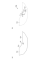
- FIG. FIGS. 2A and 2B are diagrams showing low beam light distribution and aiming light distribution. It is a figure explaining aiming.
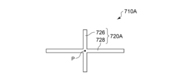
- FIG. 10 is a diagram showing aiming light distribution according to Modification 1;
- a vehicle lamp includes a variable light distribution lamp that includes a plurality of individually controllable pixels and emits lamp light having a light distribution according to the states of the plurality of pixels, and a light distribution of the variable light distribution lamp. and a controller for controlling the The aiming light distribution includes a cross pattern that crosses at locations corresponding to the elbow points of the low beam light distribution.
- the cross point of the cross pattern can be regarded as the elbow point for aiming.
- the cross pattern has a higher contrast than a normal low beam light distribution and is easy to recognize, and the vertical line of the cross pattern allows the horizontal position of the elbow point to be recognized, and the horizontal line of the cross pattern allows the vertical position of the elbow point to be recognized. Since it can be recognized, aiming becomes easy.
- the cross pattern may include two L-shaped patterns or two inverted L-shaped patterns arranged point-symmetrically with respect to the position corresponding to the elbow point.
- the elbow point can be recognized as a point having no width, accurate aiming becomes possible.
- the cross pattern may include two linear patterns that are orthogonal to each other.
- variable light distribution lamp may include an array of light emitting elements.
- variable light distribution lamp may include a light source and a spatial light modulator that patterns light emitted from the light source.
- a state in which member A is connected to member B refers to a case in which member A and member B are physically directly connected, and that member A and member B are electrically connected to each other. It also includes the case of being indirectly connected through other members that do not substantially affect the physical connection state or impair the functions and effects achieved by their combination.
- the state in which member C is provided between member A and member B refers to the case where member A and member C or member B and member C are directly connected, as well as the case where they are electrically connected. It also includes the case of being indirectly connected through other members that do not substantially affect the physical connection state or impair the functions and effects achieved by their combination.
- FIG. 1 is a block diagram of a vehicle lamp 600 according to an embodiment.
- the vehicle lamp 600 is a headlamp that is mounted on a vehicle and that illuminates a field of view in front of the vehicle with light.
- a vehicle lamp 600 includes a variable light distribution lamp unit 610 and a controller 620 .
- variable light distribution lamp unit 610 is configured to irradiate part or all of the low beam area with a beam.
- the variable light distribution lamp unit 610 includes a plurality of individually controllable pixels PIX, and emits lamp light having a light distribution according to the states of the plurality of pixels PIX.
- variable light distribution lamp unit 610 includes light emitting element array 612 and irradiation optical system 614 .
- An LED array can be used as the light emitting element array 612 .
- the brightness of each pixel PIX may be controllable with two gradations of ON and OFF, or may be controllable with multiple gradations.
- PWM dimming can be used to achieve multiple gradations. may be expressed.
- the irradiation optical system 614 projects the output light of the light emitting element array 612 forward of the vehicle.
- the irradiation optical system 614 may be a lens optical system, a reflective optical system, or a combination thereof.
- a virtual vertical screen 2 is shown in FIG. It is assumed that the virtual vertical screen 2 is a coordinate system based on the road surface. The distance between the virtual vertical screen 2 and the vehicle (lamp) can be 10m or 25m.
- Light from the variable light distribution lamp unit 610 forms a light distribution pattern PTN on the virtual vertical screen 2 .
- the light distribution pattern PTN is the intensity distribution of lamp light on the virtual vertical screen 2 and is based on the on/off pattern of the plurality of pixels PIX of the light emitting element array 612 .
- the correspondence between the position of a certain pixel and the irradiation area on the virtual vertical screen 2 corresponding to that pixel is determined by the irradiation optical system 614, and is a mirror image relationship (horizontal inversion), vertical inversion, or vertical and horizontal inversion. Sometimes it is.
- the light distribution pattern PTN includes a cutoff line CL.
- the light distribution pattern PTN includes a horizontal cutoff line CLa and an oblique cutoff line CLb, which intersect at the elbow point LB.
- the controller 620 can control the light distribution variable lamp unit 610 according to the driving scene to control the light distribution of the low beam.
- controller 620 causes variable light distribution lamp unit 610 to function as an ADB.
- controller 620 may be realized by software processing, hardware processing, or a combination of software processing and hardware processing. Specifically, software processing is implemented by combining processors (hardware) such as CPU (Central Processing Unit), MPU (Micro Processing Unit), and microcontrollers, and software programs executed by the processor (hardware). . Controller 620 may be a combination of multiple processors (microcontrollers).
- hardware processing is implemented by hardware such as ASIC (Application Specific Integrated Circuit), controller IC, and FPGA (Field Programmable Gate Array).
- ASIC Application Specific Integrated Circuit
- controller IC controller IC
- FPGA Field Programmable Gate Array
- the optical axis (aiming) of the vehicle lamp 600 is adjusted so that the elbow point LB is at a predetermined position on the screen.
- FIGS. 2A and 2B are diagrams showing low beam light distribution and aiming light distribution.
- the low beam light distribution 700 has a horizontal cutoff line CLa and an oblique cutoff line CLb, and is determined so that the illuminance above the cutoff lines CLa and CLb is substantially zero. Cutoff lines CLa and CLb intersect at elbow point EL.
- the aiming light distribution 710 includes a cross pattern 720 crossing at a position P corresponding to the elbow EL of the low beam light distribution 700 .
- Cross pattern 720 includes a horizontally extending portion and a vertically extending portion.
- the cross pattern 720 includes two inverted L-shaped patterns 722,724.
- the inverted L-shaped patterns 722 and 724 are arranged symmetrically with respect to the position P corresponding to the elbow point.
- the cross pattern 720 may be a combination of two L-shaped patterns. That is, the cross pattern 720 in FIG. 2B may be left-right reversed.
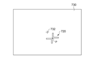
- FIG. 3 is a diagram for explaining aiming.
- FIG. 3 shows a screen 730 used for aiming.
- a target mark 732 indicating the target position of the elbow point is shown on the screen 730 .
- the vehicle equipped with the vehicle lamp 600 is placed at a predetermined position facing the screen 730 .
- an aiming mode setting signal is transmitted to the controller 200 .
- the controller 200 sets the light distribution of the variable light distribution lamp unit 610 to the aiming light distribution 710 in response to this setting signal.
- the aiming light distribution 710 including the cross pattern 720 is projected onto the screen 730 .
- the aiming operator adjusts the optical axis of the vehicle lamp 600 so that the center point P of the cross pattern 720 approaches the target mark 732 .
- the method of adjusting the optical axis is not particularly limited, it is usually performed by turning a screw for adjusting the optical axis.
- the optical axis adjustment may be performed electronically.
- the variable light distribution lamp unit 610 can form an arbitrary light distribution depending on whether the pixels PIX are turned on or off.
- the controller 620 can shift the position of the center point P of the cross pattern 720 vertically and horizontally according to the control by the operator. The operator ends aiming when the center point P of the cross pattern 720 is sufficiently close to the target mark 732 . The position of the center point P at the end of aiming is recorded in the controller 200 .
- the controller 200 receives an instruction to turn on the low beam, it generates a control signal for the low beam light distribution 700 so that the recorded position of the center point P becomes the elbow point.
- the aiming operator can regard the cross point of the cross pattern 720 as the elbow point for aiming.
- the cross pattern 720 has a higher contrast than normal low beam light distribution and is easy to recognize. Furthermore, the vertical line of the cross pattern 720 allows recognition of the horizontal position of the elbow point, and the horizontal line of the cross pattern enables recognition of the vertical position of the elbow point. Therefore, aiming is easier than in the case of projecting a low-beam light distribution onto a screen.
- FIG. 4 is a diagram showing an aiming light distribution 710A according to Modification 1. As shown in FIG. This aiming light distribution 710A includes a cross pattern 720A. Cross pattern 720A includes two linear patterns 726, 728 that are perpendicular to each other at their centers.
- This pattern also makes it possible to adjust the optical axis by using the center of the cross pattern 720A as a virtual elbow point.
- the existence position of the center point P is ambiguous by the width of the two linear patterns 726 and 728.
- the widths of the linear patterns 726 and 728 should be narrowed, but if they are too narrow, the cross pattern 720A becomes difficult to recognize.
- the center point P is clear regardless of the width of the L-shaped pattern, so it can be said that the aiming accuracy is high.
- the aiming pattern may include other patterns in addition to the cross pattern.
- the controller 620 may control the variable light distribution lamp unit 610 so that the aiming light distribution and the low beam light distribution are alternately generated in a time division manner.
- variable light distribution lamp unit 610 is configured with the light emitting element array 612, but the present disclosure is not limited thereto.
- the variable light distribution lamp unit 610 may include a light source that produces light with a substantially flat intensity distribution and a spatial light modulator that spatially patterns the light emitted from the light source. Spatial light modulators are exemplified by DMDs (Digital Micromirror Devices) and liquid crystal devices.
- the present disclosure relates to vehicle lamps.
- Virtual vertical screen 600 Vehicle lamp 610 Variable light distribution lamp unit 612 Light emitting element array 614 Irradiation optical system PIX Pixel 620 Controller 700 Low beam distribution 710 For aiming Light distribution, 720... Cross pattern, 730... Screen.
Landscapes
- Engineering & Computer Science (AREA)
- General Engineering & Computer Science (AREA)
- Mechanical Engineering (AREA)
- Physics & Mathematics (AREA)
- Microelectronics & Electronic Packaging (AREA)
- Optics & Photonics (AREA)
- Mathematical Physics (AREA)
- Non-Portable Lighting Devices Or Systems Thereof (AREA)
- Lighting Device Outwards From Vehicle And Optical Signal (AREA)
Abstract
Description
本開示のいくつかの例示的な実施形態の概要を説明する。この概要は、後述する詳細な説明の前置きとして、実施形態の基本的な理解を目的として、1つまたは複数の実施形態のいくつかの概念を簡略化して説明するものであり、発明あるいは開示の広さを限定するものではない。またこの概要は、考えられるすべての実施形態の包括的な概要ではなく、実施形態の欠くべからざる構成要素を限定するものではない。便宜上、「一実施形態」は、本明細書に開示するひとつの実施形態(実施例や変形例)または複数の実施形態(実施例や変形例)を指すものとして用いる場合がある。
以下、好適な実施の形態について図面を参照しながら説明する。各図面に示される同一または同等の構成要素、部材、処理には、同一の符号を付するものとし、適宜重複した説明は省略する。また、実施の形態は、開示を限定するものではなく例示であって、実施の形態に記述されるすべての特徴やその組み合わせは、必ずしも開示の本質的なものであるとは限らない。
上述した実施形態は例示であり、それらの各構成要素や各処理プロセスの組み合わせにいろいろな変形例が可能なことが当業者に理解される。以下、こうした変形例について説明する。
図4は、変形例1に係るエイミング用配光710Aを示す図である。このエイミング用配光710Aは、十字パターン720Aを含む。十字パターン720Aは、互いの中央において直交する2本の直線パターン726,728を含む。
エイミングパターンは、十字パターンに加えて、その他のパターンを含んでいてもよい。あるいはエイミングモードにおいて、コントローラ620は、エイミング用配光とロービーム配光が時分割で交互に発生するように、配光可変ランプユニット610を制御してもよい。
実施形態では、配光可変ランプユニット610を発光素子アレイ612で構成したが本開示はそれに限定されない。たとえば配光可変ランプユニット610は、実質的にフラットな強度分布を有する光を生成する光源と、光源の出射光を空間的にパターニングする空間光変調器と、を含んでもよい。空間光変調器は、DMD(Digital Micromirror Device)や、液晶デバイスなどが例示される。
Claims (5)
- 個別に制御可能な複数の画素を含み、前記複数の画素の状態に応じた配光を有する灯光を出射する配光可変ランプと、
前記配光可変ランプの前記配光を制御するコントローラと、
を備え、
エイミング用配光は、ロービーム配光のエルボー点に対応する位置においてクロスする十字パターンを含むことを特徴とする車両用灯具。 - 前記十字パターンは、前記エルボー点に対応する位置に関して点対称に配置される2個のL字のパターンまたは2個の逆L字のパターンを含むことを特徴とする請求項1に記載の車両用灯具。
- 前記十字パターンは、互いに直交する2本の直線パターンを含むことを特徴とする請求項1に記載の車両用灯具。
- 前記配光可変ランプは、発光素子のアレイを含むことを特徴とする請求項1から3のいずれかに記載の車両用灯具。
- 前記配光可変ランプは、光源と、前記光源の出射光をパターニングする空間光変調器と、を含むことを特徴とする請求項1から3のいずれかに記載の車両用灯具。
Priority Applications (3)
| Application Number | Priority Date | Filing Date | Title |
|---|---|---|---|
| JP2023564857A JPWO2023100648A1 (ja) | 2021-11-30 | 2022-11-15 | |
| CN202280078610.6A CN118339402A (zh) | 2021-11-30 | 2022-11-15 | 车辆用灯具 |
| US18/675,498 US12286054B2 (en) | 2021-11-30 | 2024-05-28 | Vehicle lamp apparatus |
Applications Claiming Priority (2)
| Application Number | Priority Date | Filing Date | Title |
|---|---|---|---|
| JP2021-194203 | 2021-11-30 | ||
| JP2021194203 | 2021-11-30 |
Related Child Applications (1)
| Application Number | Title | Priority Date | Filing Date |
|---|---|---|---|
| US18/675,498 Continuation US12286054B2 (en) | 2021-11-30 | 2024-05-28 | Vehicle lamp apparatus |
Publications (1)
| Publication Number | Publication Date |
|---|---|
| WO2023100648A1 true WO2023100648A1 (ja) | 2023-06-08 |
Family
ID=86612031
Family Applications (1)
| Application Number | Title | Priority Date | Filing Date |
|---|---|---|---|
| PCT/JP2022/042447 Ceased WO2023100648A1 (ja) | 2021-11-30 | 2022-11-15 | 車両用灯具 |
Country Status (4)
| Country | Link |
|---|---|
| US (1) | US12286054B2 (ja) |
| JP (1) | JPWO2023100648A1 (ja) |
| CN (1) | CN118339402A (ja) |
| WO (1) | WO2023100648A1 (ja) |
Families Citing this family (1)
| Publication number | Priority date | Publication date | Assignee | Title |
|---|---|---|---|---|
| US20250389618A1 (en) * | 2024-06-24 | 2025-12-25 | Ford Global Technologies, Llc | Pixel headlamp aiming |
Citations (4)
| Publication number | Priority date | Publication date | Assignee | Title |
|---|---|---|---|---|
| JP2007298286A (ja) * | 2006-04-27 | 2007-11-15 | Sanei Kogyo Kk | ヘッドライトテスター |
| JP2010018217A (ja) * | 2008-07-14 | 2010-01-28 | Koito Mfg Co Ltd | 車両用灯具およびその光軸調整システム |
| JP2017067656A (ja) * | 2015-09-30 | 2017-04-06 | 株式会社小糸製作所 | エルボー点検出方法、検査装置、および灯具の製造方法 |
| US10890309B1 (en) * | 2019-12-12 | 2021-01-12 | Valeo North America, Inc. | Method of aiming a high definition pixel light module |
Family Cites Families (2)
| Publication number | Priority date | Publication date | Assignee | Title |
|---|---|---|---|---|
| JP2017056828A (ja) | 2015-09-16 | 2017-03-23 | トヨタ自動車株式会社 | 車両用灯具 |
| KR101908423B1 (ko) * | 2017-04-10 | 2018-10-16 | 엘지전자 주식회사 | 차량에 구비된 차량 제어 장치 및 그것의 차량 제어 방법 |
-
2022
- 2022-11-15 WO PCT/JP2022/042447 patent/WO2023100648A1/ja not_active Ceased
- 2022-11-15 CN CN202280078610.6A patent/CN118339402A/zh active Pending
- 2022-11-15 JP JP2023564857A patent/JPWO2023100648A1/ja active Pending
-
2024
- 2024-05-28 US US18/675,498 patent/US12286054B2/en active Active
Patent Citations (4)
| Publication number | Priority date | Publication date | Assignee | Title |
|---|---|---|---|---|
| JP2007298286A (ja) * | 2006-04-27 | 2007-11-15 | Sanei Kogyo Kk | ヘッドライトテスター |
| JP2010018217A (ja) * | 2008-07-14 | 2010-01-28 | Koito Mfg Co Ltd | 車両用灯具およびその光軸調整システム |
| JP2017067656A (ja) * | 2015-09-30 | 2017-04-06 | 株式会社小糸製作所 | エルボー点検出方法、検査装置、および灯具の製造方法 |
| US10890309B1 (en) * | 2019-12-12 | 2021-01-12 | Valeo North America, Inc. | Method of aiming a high definition pixel light module |
Also Published As
| Publication number | Publication date |
|---|---|
| US20240308418A1 (en) | 2024-09-19 |
| CN118339402A (zh) | 2024-07-12 |
| JPWO2023100648A1 (ja) | 2023-06-08 |
| US12286054B2 (en) | 2025-04-29 |
Similar Documents
| Publication | Publication Date | Title |
|---|---|---|
| CN108343925B (zh) | 车辆大灯 | |
| US10598330B2 (en) | Headlight for vehicles | |
| JP5118564B2 (ja) | 車両用灯具 | |
| US10119670B2 (en) | Headlight for vehicles | |
| CN109562719B (zh) | 准稀疏光学照射 | |
| CN109311417B (zh) | 车辆大灯 | |
| KR102278904B1 (ko) | 자동차 헤드라이트용 조명 장치 | |
| CN109843647B (zh) | 用于车辆的照明装置和用于调整车辆的照明距离的方法 | |
| JPWO2018179093A1 (ja) | 車載用前照灯および光の投射方法 | |
| KR102380499B1 (ko) | 자동차 헤드램프용 광 모듈 | |
| CN107923602A (zh) | 照明系统和照明方法 | |
| US20150003100A1 (en) | Light-emitting apparatus and vehicle headlamp system | |
| CN108692276B (zh) | 具有机械致动器的光束投射装置、光学模块和设置有这种装置的前照灯 | |
| JP2019091652A (ja) | 光照射装置及び車両用灯具 | |
| JP7422148B2 (ja) | 灯具システム | |
| WO2023100648A1 (ja) | 車両用灯具 | |
| JP6268369B2 (ja) | 照明装置、車両及び照明装置の制御方法 | |
| KR102749273B1 (ko) | 자동차 헤드램프용 조명 장치 | |
| Pfullmann et al. | From mechanical ADB systems to high resolution headlamps-new opportunities of novel headlight systems | |
| JP2020057511A (ja) | 車両用灯具 | |
| JP2022139713A (ja) | 車両用灯具の制御装置、車両用灯具の制御方法、車両用灯具システム | |
| WO2021070787A1 (ja) | 車両用灯具、配光可変ランプの制御方法 | |
| JP2021150054A (ja) | 車両用灯具 | |
| KR102598839B1 (ko) | 자동차 헤드램프용 조명 장치 | |
| WO2024142991A1 (ja) | 車両用灯具、配光可変ランプのコントローラおよびその制御方法、ソフトウェアプログラム |
Legal Events
| Date | Code | Title | Description |
|---|---|---|---|
| 121 | Ep: the epo has been informed by wipo that ep was designated in this application |
Ref document number: 22901081 Country of ref document: EP Kind code of ref document: A1 |
|
| ENP | Entry into the national phase |
Ref document number: 2023564857 Country of ref document: JP Kind code of ref document: A |
|
| WWE | Wipo information: entry into national phase |
Ref document number: 202280078610.6 Country of ref document: CN |
|
| NENP | Non-entry into the national phase |
Ref country code: DE |
|
| 122 | Ep: pct application non-entry in european phase |
Ref document number: 22901081 Country of ref document: EP Kind code of ref document: A1 |