WO2023100590A1 - 要推定領域推定システム、要推定領域推定プログラム、および要推定領域推定方法 - Google Patents
要推定領域推定システム、要推定領域推定プログラム、および要推定領域推定方法 Download PDFInfo
- Publication number
- WO2023100590A1 WO2023100590A1 PCT/JP2022/041182 JP2022041182W WO2023100590A1 WO 2023100590 A1 WO2023100590 A1 WO 2023100590A1 JP 2022041182 W JP2022041182 W JP 2022041182W WO 2023100590 A1 WO2023100590 A1 WO 2023100590A1
- Authority
- WO
- WIPO (PCT)
- Prior art keywords
- estimation
- area
- estimated
- unit
- detected
- Prior art date
- Legal status (The legal status is an assumption and is not a legal conclusion. Google has not performed a legal analysis and makes no representation as to the accuracy of the status listed.)
- Ceased
Links
Images



Classifications
-
- G—PHYSICS
- G06—COMPUTING OR CALCULATING; COUNTING
- G06V—IMAGE OR VIDEO RECOGNITION OR UNDERSTANDING
- G06V20/00—Scenes; Scene-specific elements
- G06V20/50—Context or environment of the image
- G06V20/52—Surveillance or monitoring of activities, e.g. for recognising suspicious objects
-
- G—PHYSICS
- G06—COMPUTING OR CALCULATING; COUNTING
- G06T—IMAGE DATA PROCESSING OR GENERATION, IN GENERAL
- G06T7/00—Image analysis
- G06T7/20—Analysis of motion
- G06T7/215—Motion-based segmentation
-
- G—PHYSICS
- G06—COMPUTING OR CALCULATING; COUNTING
- G06T—IMAGE DATA PROCESSING OR GENERATION, IN GENERAL
- G06T7/00—Image analysis
- G06T7/20—Analysis of motion
- G06T7/246—Analysis of motion using feature-based methods, e.g. the tracking of corners or segments
- G06T7/251—Analysis of motion using feature-based methods, e.g. the tracking of corners or segments involving models
-
- G—PHYSICS
- G06—COMPUTING OR CALCULATING; COUNTING
- G06T—IMAGE DATA PROCESSING OR GENERATION, IN GENERAL
- G06T7/00—Image analysis
- G06T7/70—Determining position or orientation of objects or cameras
- G06T7/73—Determining position or orientation of objects or cameras using feature-based methods
- G06T7/75—Determining position or orientation of objects or cameras using feature-based methods involving models
-
- G—PHYSICS
- G06—COMPUTING OR CALCULATING; COUNTING
- G06T—IMAGE DATA PROCESSING OR GENERATION, IN GENERAL
- G06T7/00—Image analysis
- G06T7/70—Determining position or orientation of objects or cameras
- G06T7/77—Determining position or orientation of objects or cameras using statistical methods
-
- G—PHYSICS
- G06—COMPUTING OR CALCULATING; COUNTING
- G06T—IMAGE DATA PROCESSING OR GENERATION, IN GENERAL
- G06T7/00—Image analysis
- G06T7/90—Determination of colour characteristics
-
- G—PHYSICS
- G06—COMPUTING OR CALCULATING; COUNTING
- G06V—IMAGE OR VIDEO RECOGNITION OR UNDERSTANDING
- G06V10/00—Arrangements for image or video recognition or understanding
- G06V10/40—Extraction of image or video features
- G06V10/56—Extraction of image or video features relating to colour
-
- G—PHYSICS
- G06—COMPUTING OR CALCULATING; COUNTING
- G06V—IMAGE OR VIDEO RECOGNITION OR UNDERSTANDING
- G06V40/00—Recognition of biometric, human-related or animal-related patterns in image or video data
- G06V40/10—Human or animal bodies, e.g. vehicle occupants or pedestrians; Body parts, e.g. hands
- G06V40/103—Static body considered as a whole, e.g. static pedestrian or occupant recognition
-
- G—PHYSICS
- G06—COMPUTING OR CALCULATING; COUNTING
- G06T—IMAGE DATA PROCESSING OR GENERATION, IN GENERAL
- G06T2207/00—Indexing scheme for image analysis or image enhancement
- G06T2207/10—Image acquisition modality
- G06T2207/10016—Video; Image sequence
-
- G—PHYSICS
- G06—COMPUTING OR CALCULATING; COUNTING
- G06T—IMAGE DATA PROCESSING OR GENERATION, IN GENERAL
- G06T2207/00—Indexing scheme for image analysis or image enhancement
- G06T2207/10—Image acquisition modality
- G06T2207/10024—Color image
-
- G—PHYSICS
- G06—COMPUTING OR CALCULATING; COUNTING
- G06T—IMAGE DATA PROCESSING OR GENERATION, IN GENERAL
- G06T2207/00—Indexing scheme for image analysis or image enhancement
- G06T2207/10—Image acquisition modality
- G06T2207/10048—Infrared image
-
- G—PHYSICS
- G06—COMPUTING OR CALCULATING; COUNTING
- G06T—IMAGE DATA PROCESSING OR GENERATION, IN GENERAL
- G06T2207/00—Indexing scheme for image analysis or image enhancement
- G06T2207/20—Special algorithmic details
- G06T2207/20036—Morphological image processing
- G06T2207/20044—Skeletonization; Medial axis transform
-
- G—PHYSICS
- G06—COMPUTING OR CALCULATING; COUNTING
- G06T—IMAGE DATA PROCESSING OR GENERATION, IN GENERAL
- G06T2207/00—Indexing scheme for image analysis or image enhancement
- G06T2207/20—Special algorithmic details
- G06T2207/20076—Probabilistic image processing
-
- G—PHYSICS
- G06—COMPUTING OR CALCULATING; COUNTING
- G06T—IMAGE DATA PROCESSING OR GENERATION, IN GENERAL
- G06T2207/00—Indexing scheme for image analysis or image enhancement
- G06T2207/20—Special algorithmic details
- G06T2207/20081—Training; Learning
-
- G—PHYSICS
- G06—COMPUTING OR CALCULATING; COUNTING
- G06T—IMAGE DATA PROCESSING OR GENERATION, IN GENERAL
- G06T2207/00—Indexing scheme for image analysis or image enhancement
- G06T2207/20—Special algorithmic details
- G06T2207/20084—Artificial neural networks [ANN]
-
- G—PHYSICS
- G06—COMPUTING OR CALCULATING; COUNTING
- G06T—IMAGE DATA PROCESSING OR GENERATION, IN GENERAL
- G06T2207/00—Indexing scheme for image analysis or image enhancement
- G06T2207/30—Subject of image; Context of image processing
- G06T2207/30196—Human being; Person
Definitions
- the present invention relates to an estimation-required area estimation system, an estimation-required area estimation program, and an estimation-required area estimation method.
- Patent Document 1 discloses the following technology. Based on the image information acquired by cameras fixedly installed in the facility, the human skeleton is estimated by machine learning. Then, when the worker is hidden in the blind spot of the camera, the estimated skeleton is corrected using sensor information from a worker terminal such as a first-person viewpoint camera attached to the worker or an acceleration sensor. As a result, even if a part of the image of the person cannot be obtained, it is possible to grasp the detailed movements of the person and provide appropriate operation support to the worker.
- a worker terminal such as a first-person viewpoint camera attached to the worker or an acceleration sensor.
- Patent Literature 1 requires the worker to wear the terminal, so there is a problem that the cost increases and the work efficiency decreases due to the terminal installation. In addition, there is a problem that new learning is required when joints or regions to be estimated are added.
- An object of the present invention is to provide an area estimation program and an estimation-required area estimation method.
- An estimation-required region estimation system having a detection unit that detects joint points of an object from an image of the object, and an estimation unit that estimates an estimation-required region based on the joint points detected by the detection unit.
- a determination unit that determines whether or not the estimation required area exists based on the detected joint points, and the estimation unit determines the estimation required area when it is determined that the estimation required area does not exist.
- a correction unit for estimating and correcting the joint points by interpolating the detected joint points with the estimated area to be estimated; and a color belonging to the object based on the estimated area to be estimated.
- a correction unit that corrects the joint points by interpolating the detected joint points in the estimated estimation required area; a reception unit that receives designation of a color information acquisition area;
- estimation-required region estimation system according to any one of (1) to (6) above, further comprising an image acquisition unit that acquires the image.
- a behavior estimation unit that estimates the behavior of the object based on the corrected joint points; and specific information that individually identifies the object based on the color information acquired by the color information acquisition unit. and an output unit for outputting the behavior estimated by the behavior estimation unit and the specific information determined by the specific information determination unit in association with each object.
- step (b) the estimation-required region in the frame in which the joint point is detected is estimated based on the joint point detected in the frame of the image. Estimated area estimation program.
- the processing includes a step (c) of determining whether or not the estimation-required region exists based on the detected joint points, and in the step (b), it is determined that the estimation-required region does not exist. if so, estimating the region to be estimated, the processing includes a step (d) of correcting the joint points by interpolating the detected joint points with the estimated region to be estimated; (12) or (13), further comprising a step (e) of obtaining color information belonging to the object from the image based on the estimated area to be estimated.
- step (b) The above-described (15), wherein in step (b), the estimation-required region in the frame in which the joint point is detected is estimated based on the joint point detected in the frame of the image. Estimation required area estimation method.
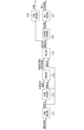
- FIG. 4 shows schematic structure of an analysis system. It is a block diagram which shows the hardware constitutions of an analysis apparatus. 4 is a block diagram showing functions of a control unit of the analysis device; FIG. FIG. 4 is an explanatory diagram showing a method of estimating an estimation required area; It is a flow chart which shows operation of an analysis device. 4 is a block diagram showing functions of a control unit of the analysis device; FIG.
- FIG. 1 is a diagram showing a schematic configuration of an analysis system 10. As shown in FIG. The analysis system 10 constitutes an estimation required area estimation system.
- the analysis system 10 includes an analysis device 100, an imaging device 200, and a communication network 300.
- the analysis device 100 is connected to the imaging device 200 via a communication network 300 so as to be able to communicate with each other.
- the analysis system 10 can be configured only with the analysis device 100 .
- the imaging device 200 constitutes an image acquisition unit.
- the analysis device 100 detects the joint points 410 (see FIG. 4) of the object included in the captured image received from the imaging device 200, estimates an estimation required region described later based on the joint points 410, and estimates the estimated estimation required region.
- the joint point 410 is corrected by complementing the joint point 410 with .
- the analysis device 100 estimates the behavior of the object based on the corrected joint points 410, and determines specific information that individually identifies the object based on the obtained color information of the estimation-required area.
- the object may be an articulated object such as a person. In the following, for the sake of simplicity, the object is assumed to be a human subject 400 (see FIG. 4).
- the photographing device 200 is configured by, for example, a near-infrared camera, is installed at a predetermined position, and photographs the photographing area from the predetermined position.
- the imaging device 200 irradiates a near-infrared light toward an imaging area with an LED (Light Emitting Device), and receives near-infrared light reflected by an object in the imaging area with a CMOS (Complementary Metal Oxide Semiconductor) sensor. , the imaging area can be photographed.
- the captured image may be a monochrome image in which each pixel has a reflectance of near-infrared rays.
- the predetermined position may be, for example, the ceiling of the manufacturing plant where the subject 400 works as a worker.
- the imaging area can be, for example, a three-dimensional area that includes the entire floor of a manufacturing plant.
- the photographing device 200 can photograph the photographing area as a moving image composed of a plurality of photographed images (frames) at a frame rate of 15 fps to 30 fps, for example.
- a network interface based on a wired communication standard such as Ethernet (registered trademark) can be used for the communication network 300 .
- the communication network 300 may use a network interface based on wireless communication standards such as Bluetooth (registered trademark) and IEEE802.11.
- FIG. 2 is a block diagram showing the hardware configuration of the analysis device 100.
- Analysis device 100 includes control unit 110 , storage unit 120 , communication unit 130 , and operation display unit 140 . These components are interconnected via bus 150 .
- Analysis device 100 may be configured by a computer.
- the control unit 110 is composed of a CPU (Central Processing Unit), and performs control and arithmetic processing of each unit of the analysis device 100 according to a program. Details of the functions of the control unit 110 will be described later.
- CPU Central Processing Unit
- the storage unit 120 can be composed of RAM (Random Access Memory), ROM (Read Only Memory), and flash memory.
- the RAM temporarily stores programs and data as a work area for the control unit 110 .
- the ROM stores various programs and various data in advance.
- the flash memory stores various programs including an operating system and various data.
- the communication unit 130 is an interface for communicating with external devices.
- Network interfaces conforming to standards such as Ethernet (registered trademark), SATA, PCI Express, USB, and IEEE1394 can be used for communication.
- wireless communication interfaces such as Bluetooth (registered trademark), IEEE802.11, and 4G can be used for communication.
- the communication unit 130 receives the captured image from the imaging device 200 .
- the operation display unit 140 is composed of, for example, a liquid crystal display, a touch panel, and various keys.
- the operation display unit 140 receives various operations and inputs, and displays various information.
- control unit 110 The function of the control unit 110 will be explained.
- FIG. 3 is a block diagram showing functions of the control unit 110 of the analysis device 100.
- Control unit 110 functions as position detection unit 111, loss determination unit 112, estimation unit 113, correction unit 114, color information acquisition unit 115, behavior estimation unit 116, and individual determination unit 117 by executing programs.
- the position detection unit 111 constitutes a detection unit.
- the loss determination unit 112 constitutes a determination unit.
- the individual determination unit 117 constitutes a specific information determination unit.
- Action estimation unit 116 and individual determination unit 117 constitute an output unit.
- the position detection unit 111 detects joint points 410 of the subject 400 from the captured image of the object. Specifically, the position detection unit 111 detects the joint point 410, for example, as coordinates of a pixel in the captured image. When a plurality of subjects 400 are included in the captured image, the position detection unit 111 detects the joint point 410 for each subject 400 . For the sake of simplicity, it is assumed that there is only one target person 400 included in the photographed image.
- the position detection unit 111 detects the joint point 410 by estimating it from the captured image using machine learning.
- the position detection unit 111 can detect the joint point 410 using known deep learning such as Deep Pose, CNN (Convolution Neural Network), and Res Net.
- the position detection unit 111 may detect the joint point 410 using machine learning other than deep learning, such as SVM (Support Vector Machine) and Random Forest.
- Joint points 410 may include, for example, the head, nose, neck, shoulders, elbows, wrists, hips, knees, ankles, eyes, and ears. A case where the joint points 410 detected by the position detection unit 111 are five joint points 410 of the neck, shoulders (right shoulder and left shoulder), and hips (right hip and left hip) will be described below as an example.
- the position detection unit 111 calculates the likelihood for each pixel of the captured image for each class of the joint point 410 of the subject 400 (classification of the joint point 410 such as left shoulder, right shoulder, left hip, etc.). Pixels that have a likelihood can be detected as articulation points 410 . Therefore, a pixel with a likelihood lower than the predetermined threshold is not detected as the joint point 410 . Therefore, part of the joint point 410 may not be detected depending on the degree of clarity of the image of the subject 400 in the captured image, the influence of occlusion, and the like.
- the missing determination unit 112 determines whether or not there is a missing joint point 410 or the like due to a part of the joint point 410 not being detected (estimated) for some reason. 410 to determine. Specifically, loss determining section 112 determines whether or not there are joint points 410 that have not been detected and/or regions that include joint points 410 and that need to be estimated (hereinafter referred to as “estimation-required regions”). judge.
- the presence of the estimation-required region corresponds to the presence of a defect such as the joint point 410 . Absence of the estimation-required region corresponds to absence of defects such as joint points 410 .
- the area including the joint point 410 is, for example, a square area of a predetermined size centered on the joint point 410 .
- the estimation required area can be set in advance.
- the estimation-required area includes (1) an area that could not be obtained (detected) due to the installation position of the imaging device 200, and (2) an area that is not originally planned to be detected (acquired) by the position detection unit 111. (an area not set to be detected by the position detection unit 111).
- the missing determination unit 112 determines, for example, the class of the joint points 410 of the subject 400 detected by the position detection unit 111 (classification of joint points such as the left shoulder, right shoulder, and left hip) and necessary joint points 410 (hereinafter referred to as simply referred to as "necessary joint points"), it is determined whether or not there is an estimation required region.
- the necessary joint points include (a) the joint points 41 set to be detected by the position detection unit 111 0 and (b) a joint point 410 that is not set to be detected by the position detection unit 111 but is necessary for acquiring color information described later.
- the loss determination unit 112 determines that the joint points 410 set to be detected by the position detection unit 111 include the joint point 410 of the “left shoulder” and the joint points 410 detected by the position detection unit 111 are detected. If the "left shoulder" joint point 410 is not included in the point 410, the "left shoulder” joint point 410 corresponds to the region requiring estimation in (1) above, so it is determined that there is a region requiring estimation.
- the necessary joint points are not set to be detected by the position detection unit 111 corresponding to (b) above, but the joint points 410 necessary for obtaining color information are included, the color information
- the joint point 410 or a region including the joint point 410 (hereinafter also referred to as a “specific region”) necessary for obtaining is the estimation required region. This is because the specific region corresponds to the region requiring estimation in (2) above. Therefore, when there is a specific region, the loss determination unit 112 determines that there is an estimation required region.
- the specific region includes the “head” joint point 410a (see FIG. 4) or the head region 410s including the “head” joint point 410a.
- the estimating unit 113 estimates an estimation required region based on the joint points 410 detected by the position detecting unit 111 . More specifically, the estimation unit 113 estimates the estimation-required region based on the joint points 410 detected by the position detection unit 111 and the loss determination result by the loss determination unit 112 . Specifically, the estimating unit 113 estimates the estimation-required area when it is determined that there is no estimation-required area in the loss determination result.
- the loss determination result by the loss determination unit 112 may include information specifying the presence or absence of an estimation required region and the estimation required region determined to be absent. Note that if there is information specifying an estimation required area determined to be absent in the loss determination result, the presence or absence of the estimation required area can be omitted. This is because it can be determined that there is an estimation required area if information specifying the estimation required area determined to be absent is included in the loss determination result.
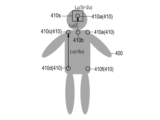
- FIG. 4 is an explanatory diagram showing a method of estimating the estimation required area.
- the image of the target person 400 in the captured image is shown as a gray shape for ease of explanation.
- the head area 410s which is the specific area, is the estimation required area.
- the estimation-required region may be other than the head region 410s. That is, the estimation-required region can be any joint point 410 and a region containing any joint point 410 .
- the estimation required area is assumed to be the head area 410s including the joint points 410a of the "head", which is the specific area, unless otherwise specified.
- the "head” joint point 410a can be estimated, for example, by calculating from the "right shoulder” joint point 410c, the "right hip” joint point 410d, and the "neck” joint point 410b. Specifically, a vector (Lu) is calculated with the starting point at the "right hip” joint point 410d and the ending point at the "right shoulder” joint point 410c. A vector (Lu/2) whose starting point is the joint point 410b of the "neck” is calculated with half the size of the vector (Lu). As a result, the joint point 410a of the "head” is calculated as the end point of the vector (Lu/2).
- a head region 410s which is a square range whose center is the joint point 410a of the "head” and whose length of one side is 1/3 of the size of the vector (Lu), is calculated (estimated) as an estimation required region.
- the region to be estimated is defined by the upper left coordinates, where u is 1/6 of the magnitude of the vector (Lu) (upper body vector), and (x, y) is the coordinates of the joint point 410a of the "head”. It can be calculated (estimated) as a square range with (xu, yu) and the lower right coordinate as (x+u, y+u).
- the estimation-required region may be estimated by machine learning based on the "right shoulder” joint point 410c, the "right waist” joint point 410d, and the “neck” joint point 410b.
- the estimation-required region may be estimated based on the joint points 410 other than the "right shoulder” joint point 410c, the "right waist” joint point 410d, and the "neck” joint point 410b.
- the estimation unit 113 can switch the size of the estimation required area according to the estimation required area.
- the color information acquisition unit 115 acquires the color information of the estimation required area
- the individual determination unit 117 determines the target person 400 based on the color information. This is because, when the target person 400 wears a hat or the like with a color that can identify the individual, the individual target person 400 can be identified by acquiring the color information of the head region 410s, which is the estimation-required region. . For this reason, by switching the size of the estimation-required region according to the size and range of a specific object worn by the target person 400 and by which the target person 400 can identify an individual, the color of the specific object can be changed. By improving the detection sensitivity, it is possible to improve the accuracy of identifying the target person 400 individually.
- the correction unit 114 corrects the joint points 410 detected by the position detection unit 111 by interpolating the joint points 410 detected by the position detection unit 111 with the estimation required area estimated by the estimation unit 113 .
- the color information acquisition unit 115 acquires the color information of the estimation-required region included in the joint points 410 corrected by the correction unit 114 from the captured image as the color information belonging to the subject 400 (object).
- the color information is, for example, the average of pixel values included in the estimation-required area in the captured image.
- the area from which color information is acquired by the color information acquisition unit 115 is not limited to the estimation required area.
- the color information acquisition unit 115 may acquire the color information of the arbitrary joint point 410 or the color information of the area including the arbitrary joint point 410 from the captured image.
- the joint point 410 from which color information is to be obtained or the area including the joint point 410 can be set in advance by storing in the storage unit 120 or the like.
- the behavior estimation unit 116 estimates the behavior of the subject 400 based on the joint points 410 corrected by the correction unit 114 .
- the behavior estimating unit 116 can estimate the behavior of the subject 400, for example, based on the difference in posture due to the joint points 410 estimated for each of the frames of the captured images that are adjacent in time series.
- the difference may be an average or a sum of the differences for each corresponding joint point 410 of the joint points 410 respectively estimated for a plurality of captured image frames adjacent in time series.
- a fall motion may be estimated by the fact that the difference in posture due to the joint point 410 becomes almost zero after the difference in posture exceeds a predetermined threshold.
- the behavior estimation unit 116 can estimate the behavior of the subject 400 based on the corrected joint points 410 using any known behavior estimation method.
- the individual determination unit 117 determines the target person 400 based on the color information acquired by the color information acquisition unit 115 . Determining the individual subject 400 based on the color information corresponds to determining specific information that identifies the subject 400 (object) based on the color information. Specific information includes, for example, information that can identify an individual, such as a name. Specifically, for example, the individual determination unit 117 refers to a table in which the color information and the name of the subject, which corresponds to the specific information, are associated with each other. By specifying the name of the target person 400 individual.
- the target person 400 By acquiring the color information of the head region 410s, which is the region to be estimated, as the color information, for example, when the target person 400 wears a cap of a color that can identify the individual, the target person 400 individuals can be judged.
- the region from which the color information acquisition unit 115 acquires color information is the region including the joint point 410 of the “elbow”. By doing so, the individual 400 subjects can be determined based on the color information. Further, when the color of the work clothes worn by the subject 400 on the lower half of the body is a color that can identify an individual, the region from which the color information acquisition unit 115 acquires color information is the region including the joint point 410 of the “knee”. By doing so, the individual 400 subjects can be determined based on the color information.
- the behavior estimation unit 116 and the individual determination unit 117 can output the behavior estimation result and the determination result of the target person 400 in association with each other for each target person 400 . This makes it possible to grasp the behavior of each of the 400 individual subjects.
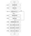
- FIG. 5 is a flow chart showing the operation of the analysis device 100. As shown in FIG. This flowchart can be executed by the control unit 110 of the analysis device 100 according to a program. step S1 02 to S107 can be executed for each frame of the captured image.
- the control unit 110 acquires the captured image by receiving it from the imaging device 200 (S101).
- the control unit 110 detects the joint points 410 of the subject 400 from the captured image (S102).
- the control unit 110 determines whether there is an estimation required area (S103). For example, the control unit 110 compares the class of the detected joint point 410 with the class of the required joint point, and if the class of the detected joint point 410 does not have a part of the class of the required joint point, It is determined that there is an estimation required area in .
- control unit 110 determines that there is no region requiring estimation (S103: NO), it executes step S106.
- control unit 110 determines that there is an estimation required area (S103: YES), it estimates the estimation required area (S104).
- the control unit 110 corrects the detected joint point 410 by complementing it with the estimated area requiring estimation (S105).
- the control unit 110 acquires color information from the captured image (S106). If there is an estimation required area, the control unit 110 can acquire the color information of the estimated estimation required area from the captured image. If there is no estimation-required region, the control unit 110 can acquire the preset joint point 410 from which color information is to be acquired or the color information of the region including the joint point 410 from the captured image.
- the control unit 110 determines the target person 400 from the acquired color information (S107).
- the control unit 110 determines the behavior of the subject 400 based on the corrected joint points 410 in step S105 (S108).
- the control unit 110 associates the determined individual with the action and outputs (S109).
- the output may include transmission to an external device, transmission without specifying a destination, display on the operation display unit 140 or the like, and the like.
- FIG. 6 is a block diagram showing functions of the control unit 110 of the analysis device 100. As shown in FIG. By executing a program, control unit 110 performs position detection unit 111, loss determination unit 112, estimation unit 113, correction unit 114, color information acquisition unit 115, behavior estimation unit 116, individual determination unit 117, reception unit 118, and functions as a switching unit 119 .
- the accepting unit 118 accepts the specification of the color acquisition area input to the operation display unit 104 by the user.
- a color acquisition area is an area from which color information is acquired by the color information acquisition unit 115 .
- the specification of the color acquisition area can be specified by the joint point 410 (for example, the joint point 410 c of the “right shoulder”) or the area including the joint point 410 .
- the color acquisition area can be the coordinates corresponding to the joint points 410 or an area of a predetermined size including the coordinates corresponding to the joint points 410 .
- the color information acquisition unit 115 identifies the color acquisition area based on the specification of the color acquisition area, and acquires the color information of the identified color acquisition area from the captured image.
- the switching unit 119 generates switching information for switching the size of the color acquisition region based on the specified color acquisition region, and determines the size of the color acquisition region for which the color information acquisition unit 115 acquires color information from the captured image. switch between Specifically, the switching unit 119 changes the size of the color acquisition area based on the specified color acquisition area by referring to a table in which the color acquisition area and the size of the color acquisition area are associated with each other, for example. switch.
- the relationship between the color acquisition area and the size of the color acquisition area can be appropriately set according to the size and range of work clothes, a name tag, or the like that is worn by the subject 400 and has an identifiable color.
- the color acquisition area can be set to any area. can be obtained. For example, if the target person 400 is wearing a cap of a color that can identify the individual, the color information of the cap can be obtained by specifying the joint point 410 of the "head" as the color acquisition area. can be If the color of the work clothes worn by the subject 400 on the upper body is a color that can identify an individual, by specifying the joint point 410 of the "elbow" as the color acquisition area, the color information of a hat or the like is acquired as the color information.
- the color information of a hat or the like can be obtained by specifying the joint point 410 of the "knee" as the color acquisition area. can be obtained.
- the embodiment has the following effects.
- an estimation-required region is estimated in the frame in which the joint points are detected. This makes it possible to estimate the estimation-required area more easily.
- the estimation required area is estimated.
- the joint points are corrected by interpolating the detected joint points with the estimated area to be estimated. Then, based on the estimated estimation required area, color information belonging to the object is acquired from the image. As a result, the accuracy of estimating the behavior of the object can be improved, and the color information belonging to the object can be obtained easily and with high accuracy.
- the joint points are corrected, the specification of the color information acquisition area is received, and based on the specification of the color information acquisition area, Accompanying color information is obtained from the image. As a result, it is possible to improve the accuracy of estimating the behavior of the object, and to acquire the color information belonging to the object flexibly and easily.
- the size of the estimation required area is switched according to the estimation required area. As a result, the object identification sensitivity based on color information can be improved.
- the estimation required area be the joint point or the area containing the joint point. This makes it possible to easily and appropriately estimate the estimation-required region.
- it has an image acquisition unit that acquires an image.
- joint points can be detected with high accuracy using an appropriate image.
- the object included in the image be an object with joints.
- detection accuracy can be improved while expanding the detection target of joint points.
- the region to be estimated be the region containing the joint points of the head.
- the estimation-required region can be estimated more easily and accurately.
- the joint points are corrected, and the behavior of the object is estimated based on the corrected joint points. Identifying information for identifying an object is determined based on the acquired color information. Then, the estimated behavior and the determined specific information are associated with each object and output. This makes it easier and more accurate to visualize individual behavior.
- the present invention is not limited to the embodiments described above.
- part or all of the processing executed by the program in the embodiment may be executed by replacing it with hardware such as a circuit.
- 10 analysis system 100 analyzer, 110 control unit, 111 position detector, 112 defect determination unit, 113 estimator, 114 corrector, 115 color information acquisition unit, 116 action estimator, 117 Personal Judgment Department, 118 Reception Department, 119 switching unit, 120 storage unit, 130 Communication Department, 140 operation display unit, 200 imaging device, 300 communication network.
Landscapes
- Engineering & Computer Science (AREA)
- Physics & Mathematics (AREA)
- General Physics & Mathematics (AREA)
- Theoretical Computer Science (AREA)
- Multimedia (AREA)
- Computer Vision & Pattern Recognition (AREA)
- Bioinformatics & Computational Biology (AREA)
- Life Sciences & Earth Sciences (AREA)
- Bioinformatics & Cheminformatics (AREA)
- Evolutionary Biology (AREA)
- Probability & Statistics with Applications (AREA)
- Human Computer Interaction (AREA)
- Image Analysis (AREA)
- Image Processing (AREA)
Priority Applications (3)
| Application Number | Priority Date | Filing Date | Title |
|---|---|---|---|
| JP2023564830A JPWO2023100590A1 (https=) | 2021-12-03 | 2022-11-04 | |
| US18/713,914 US20250029263A1 (en) | 2021-12-03 | 2022-11-04 | Region estimation system, region estimation program, and region estimation method |
| CN202280078663.8A CN118339580A (zh) | 2021-12-03 | 2022-11-04 | 要推测区域推测系统、要推测区域推测程序以及要推测区域推测方法 |
Applications Claiming Priority (2)
| Application Number | Priority Date | Filing Date | Title |
|---|---|---|---|
| JP2021-196700 | 2021-12-03 | ||
| JP2021196700 | 2021-12-03 |
Publications (1)
| Publication Number | Publication Date |
|---|---|
| WO2023100590A1 true WO2023100590A1 (ja) | 2023-06-08 |
Family
ID=86611969
Family Applications (1)
| Application Number | Title | Priority Date | Filing Date |
|---|---|---|---|
| PCT/JP2022/041182 Ceased WO2023100590A1 (ja) | 2021-12-03 | 2022-11-04 | 要推定領域推定システム、要推定領域推定プログラム、および要推定領域推定方法 |
Country Status (4)
| Country | Link |
|---|---|
| US (1) | US20250029263A1 (https=) |
| JP (1) | JPWO2023100590A1 (https=) |
| CN (1) | CN118339580A (https=) |
| WO (1) | WO2023100590A1 (https=) |
Families Citing this family (1)
| Publication number | Priority date | Publication date | Assignee | Title |
|---|---|---|---|---|
| JPWO2023119906A1 (https=) * | 2021-12-23 | 2023-06-29 |
Citations (4)
| Publication number | Priority date | Publication date | Assignee | Title |
|---|---|---|---|---|
| JP2017034511A (ja) * | 2015-08-03 | 2017-02-09 | 株式会社ブイ・アール・テクノセンター | 移動体検出システム |
| JP2017068431A (ja) * | 2015-09-29 | 2017-04-06 | 富士重工業株式会社 | 負担評価装置、負担評価方法 |
| JP2020135551A (ja) * | 2019-02-21 | 2020-08-31 | セコム株式会社 | 対象物認識装置、対象物認識方法、及び対象物認識プログラム |
| JP2021081836A (ja) * | 2019-11-15 | 2021-05-27 | アイシン精機株式会社 | 体格推定装置および姿勢推定装置 |
-
2022
- 2022-11-04 JP JP2023564830A patent/JPWO2023100590A1/ja active Pending
- 2022-11-04 CN CN202280078663.8A patent/CN118339580A/zh active Pending
- 2022-11-04 WO PCT/JP2022/041182 patent/WO2023100590A1/ja not_active Ceased
- 2022-11-04 US US18/713,914 patent/US20250029263A1/en active Pending
Patent Citations (4)
| Publication number | Priority date | Publication date | Assignee | Title |
|---|---|---|---|---|
| JP2017034511A (ja) * | 2015-08-03 | 2017-02-09 | 株式会社ブイ・アール・テクノセンター | 移動体検出システム |
| JP2017068431A (ja) * | 2015-09-29 | 2017-04-06 | 富士重工業株式会社 | 負担評価装置、負担評価方法 |
| JP2020135551A (ja) * | 2019-02-21 | 2020-08-31 | セコム株式会社 | 対象物認識装置、対象物認識方法、及び対象物認識プログラム |
| JP2021081836A (ja) * | 2019-11-15 | 2021-05-27 | アイシン精機株式会社 | 体格推定装置および姿勢推定装置 |
Also Published As
| Publication number | Publication date |
|---|---|
| CN118339580A (zh) | 2024-07-12 |
| JPWO2023100590A1 (https=) | 2023-06-08 |
| US20250029263A1 (en) | 2025-01-23 |
Similar Documents
| Publication | Publication Date | Title |
|---|---|---|
| JP6587489B2 (ja) | 画像処理装置、画像処理方法および画像処理システム | |
| US11298050B2 (en) | Posture estimation device, behavior estimation device, storage medium storing posture estimation program, and posture estimation method | |
| JP4670303B2 (ja) | 画像処理方法及び画像処理装置 | |
| CN111553229A (zh) | 基于三维骨骼与lstm的工人动作识别方法及装置 | |
| WO2018087853A1 (ja) | 立体画像生成システム、立体画像生成方法及び立体画像生成プログラム | |
| JP7633588B2 (ja) | 動作認識装置、動作認識方法及び動作認識プログラム | |
| WO2023100590A1 (ja) | 要推定領域推定システム、要推定領域推定プログラム、および要推定領域推定方法 | |
| AU2018456044B2 (en) | Anthropometric data portable acquisition device and method of collecting anthropometric data | |
| JP2022006919A (ja) | 動作認識システム、方法及びプログラム | |
| KR102866156B1 (ko) | 무인 순찰 로봇 및 이의 사람 자세 분석 방법 | |
| TWI815593B (zh) | 用於偵測手勢的方法和系統,以及電腦可讀儲存媒體 | |
| CN113271848A (zh) | 身体健康状态影像分析装置、方法以及系统 | |
| JP2020087040A (ja) | 特定姿勢検出装置 | |
| JP2011002292A (ja) | 三次元指先位置検出方法、三次元指先位置検出装置、およびプログラム | |
| WO2019074868A1 (en) | SYSTEMS AND METHODS FOR CALIBRATING AN EYE MONITORING SYSTEM | |
| EP3971683A1 (en) | Human body portion tracking method and human body portion tracking system | |
| US20220058830A1 (en) | Information processing apparatus, information processing method, and program | |
| US11783492B2 (en) | Human body portion tracking method and human body portion tracking system | |
| WO2022209638A1 (ja) | 作業指示システム | |
| KR102706055B1 (ko) | 라이다 장착 스마트 기기를 활용한 3차원 인체 골격 정보 추출 방법 | |
| JP7408731B1 (ja) | 行動検知方法、行動検知装置、行動検知システム | |
| US12573084B2 (en) | Information processing system, information processing method, and information processing program | |
| JP7816589B1 (ja) | 骨格検出装置、骨格検出システム、骨格検出方法及びプログラム | |
| US20250240389A1 (en) | Watching monitoring device and watching monitoring method | |
| Yun et al. | Gait Analysis Based on 3D Reconstruction Using Human Skeleton Detection and Humanoid Model with a Monocular Camera |
Legal Events
| Date | Code | Title | Description |
|---|---|---|---|
| 121 | Ep: the epo has been informed by wipo that ep was designated in this application |
Ref document number: 22901023 Country of ref document: EP Kind code of ref document: A1 |
|
| ENP | Entry into the national phase |
Ref document number: 2023564830 Country of ref document: JP Kind code of ref document: A |
|
| WWE | Wipo information: entry into national phase |
Ref document number: 18713914 Country of ref document: US Ref document number: 202280078663.8 Country of ref document: CN |
|
| NENP | Non-entry into the national phase |
Ref country code: DE |
|
| 122 | Ep: pct application non-entry in european phase |
Ref document number: 22901023 Country of ref document: EP Kind code of ref document: A1 |