WO2023100337A1 - データ提供プログラム、データ提供装置、プログラマブル表示システム、プログラマブル表示器、及びデータ提供方法 - Google Patents
データ提供プログラム、データ提供装置、プログラマブル表示システム、プログラマブル表示器、及びデータ提供方法 Download PDFInfo
- Publication number
- WO2023100337A1 WO2023100337A1 PCT/JP2021/044383 JP2021044383W WO2023100337A1 WO 2023100337 A1 WO2023100337 A1 WO 2023100337A1 JP 2021044383 W JP2021044383 W JP 2021044383W WO 2023100337 A1 WO2023100337 A1 WO 2023100337A1
- Authority
- WO
- WIPO (PCT)
- Prior art keywords
- data
- screen size
- image data
- display
- programmable display
- Prior art date
- Legal status (The legal status is an assumption and is not a legal conclusion. Google has not performed a legal analysis and makes no representation as to the accuracy of the status listed.)
- Ceased
Links
Images






Classifications
-
- G—PHYSICS
- G05—CONTROLLING; REGULATING
- G05B—CONTROL OR REGULATING SYSTEMS IN GENERAL; FUNCTIONAL ELEMENTS OF SUCH SYSTEMS; MONITORING OR TESTING ARRANGEMENTS FOR SUCH SYSTEMS OR ELEMENTS
- G05B19/00—Program-control systems
- G05B19/02—Program-control systems electric
- G05B19/04—Program control other than numerical control, i.e. in sequence controllers or logic controllers
- G05B19/05—Programmable logic controllers, e.g. simulating logic interconnections of signals according to ladder diagrams or function charts
-
- G—PHYSICS
- G05—CONTROLLING; REGULATING
- G05B—CONTROL OR REGULATING SYSTEMS IN GENERAL; FUNCTIONAL ELEMENTS OF SUCH SYSTEMS; MONITORING OR TESTING ARRANGEMENTS FOR SUCH SYSTEMS OR ELEMENTS
- G05B2219/00—Program-control systems
- G05B2219/10—Plc systems
- G05B2219/13—Plc programming
- G05B2219/13144—GUI graphical user interface, icon, function bloc editor, OI operator interface
-
- G—PHYSICS
- G06—COMPUTING OR CALCULATING; COUNTING
- G06F—ELECTRIC DIGITAL DATA PROCESSING
- G06F3/00—Input arrangements for transferring data to be processed into a form capable of being handled by the computer; Output arrangements for transferring data from processing unit to output unit, e.g. interface arrangements
- G06F3/14—Digital output to display device ; Cooperation and interconnection of the display device with other functional units
-
- G—PHYSICS
- G09—EDUCATION; CRYPTOGRAPHY; DISPLAY; ADVERTISING; SEALS
- G09G—ARRANGEMENTS OR CIRCUITS FOR CONTROL OF INDICATING DEVICES USING STATIC MEANS TO PRESENT VARIABLE INFORMATION
- G09G2340/00—Aspects of display data processing
- G09G2340/04—Changes in size, position or resolution of an image
- G09G2340/0442—Handling or displaying different aspect ratios, or changing the aspect ratio
-
- G—PHYSICS
- G09—EDUCATION; CRYPTOGRAPHY; DISPLAY; ADVERTISING; SEALS
- G09G—ARRANGEMENTS OR CIRCUITS FOR CONTROL OF INDICATING DEVICES USING STATIC MEANS TO PRESENT VARIABLE INFORMATION
- G09G2340/00—Aspects of display data processing
- G09G2340/04—Changes in size, position or resolution of an image
- G09G2340/045—Zooming at least part of an image, i.e. enlarging it or shrinking it
-
- G—PHYSICS
- G09—EDUCATION; CRYPTOGRAPHY; DISPLAY; ADVERTISING; SEALS
- G09G—ARRANGEMENTS OR CIRCUITS FOR CONTROL OF INDICATING DEVICES USING STATIC MEANS TO PRESENT VARIABLE INFORMATION
- G09G5/00—Control arrangements or circuits for visual indicators common to cathode-ray tube indicators and other visual indicators
- G09G5/36—Control arrangements or circuits for visual indicators common to cathode-ray tube indicators and other visual indicators characterised by the display of a graphic pattern, e.g. using an all-points-addressable [APA] memory
- G09G5/39—Control of the bit-mapped memory
- G09G5/391—Resolution modifying circuits, e.g. variable screen formats
Definitions
- the present disclosure includes a data providing program, a data providing device, a programmable display system, a programmable display, and a data providing method
- a programmable display is known as a human machine interface (HMI) for a programmable logic controller (PLC) that controls manufacturing equipment in manufacturing lines and manufacturing plants.
- HMI human machine interface
- PLC programmable logic controller
- Patent Document 1 there is also known a data providing device that provides image data representing an image to be displayed on the display screen of a programmable display to each of a plurality of programmable displays. .
- the screen sizes of the display screens of the plurality of programmable displays that acquire image data from the data providing device are different from each other.
- screen size means a size expressed in units of pixels, and is expressed as n ⁇ m pixels.
- n is the number of pixels in the horizontal direction
- m is the number of pixels in the vertical direction.
- Screen size is also called screen resolution.
- screen size is used not only for the display screen, but also for image data representing an image displayed on the display screen. That is, the size of an image represented as information by image data expressed in units of pixels is also called the screen size.
- the screen size of the tangible display screen is particularly called “physical screen size”
- the screen size represented by immaterial image data as information is particularly called “data screen size”.
- Patent Document 1 four programmable displays each having a physical screen size of 320 x 240 pixels, 640 x 480 pixels, 800 x 600 pixels, and 1024 x 768 pixels, and one is communicably connected to the data providing device.
- the data providing device performs the following processing in order to display the image data in an appropriate size on the display screen of each programmable display. First, the data providing device performs absolute-relative coordinate conversion processing for converting the absolute coordinates of each item included in the original image data created by the user into relative coordinates.
- the data providing device performs relative-to-absolute coordinate conversion processing by multiplying the relative coordinates represented by the relative information image data obtained by the absolute-to-relative coordinate conversion processing by the physical screen size of the programmable display device of the destination.
- Patent Document 1 transmits image data after performing relative-absolute coordinate conversion processing for each programmable display device of the transmission destination.
- Patent document 1 also discloses a configuration for causing each programmable display to perform the above-described relative-to-absolute coordinate conversion processing.
- each programmable display is to perform the relative-absolute coordinate conversion process
- the task of specifying the physical screen size of the programmable display to the data providing device can be omitted.
- the user must either specify the physical screen size of the programmable display at each programmable display, or, for each programmable display, use firmware that performs relative-to-absolute coordinate conversion processing unique to that programmable display. (firmware) must be prepared.
- An object of the present disclosure is to provide a technique that allows easy setup even when it is necessary to set up a plurality of programmable displays with different physical screen sizes.
- the data provision program is A computer that provides project data including image data to be displayed on a display screen of a programmable display to the programmable display, a creation environment providing function for providing a creation environment for creating the project data; a transmission function that transmits the project data created using the creation environment to the programmable display together with firmware that defines the operation of the programmable display; to realize
- the firmware is an installation destination physical screen size recognition function for recognizing an installation destination physical screen size, which is the screen size of the display screen of the programmable display on which the firmware is installed;
- an auto-fit processing function that performs auto-fit processing for enlarging or reducing the data screen size under the condition that the data screen size can be approximated to the physical screen size;
- a display control function for displaying the image data subjected to the autofit processing by the autofit processing function on the display screen of the programmable display; is implemented in the programmable display.
- the firmware enables the programmable display to implement the autofit processing function. Therefore, even if it is necessary to set up a plurality of programmable displays with different physical screen sizes, there is no need to change the data screen size of the image data for each programmable display to which it is sent. Project data sent to programmable displays can be shared.
- the firmware causes the programmable display device to realize the function of recognizing the physical screen size of the installation destination. Therefore, even if it is necessary to set up multiple programmable displays with different physical screen sizes, there is no need to prepare individual firmware for each programmable display at the destination.
- the transmitted firmware can be shared.
- the project data and firmware to be sent to the programmable displays can be shared. This makes it easy to set up the programmable display.
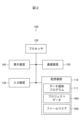
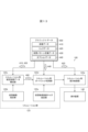
- FIG. 1 is a conceptual diagram showing the configuration of a programmable display system according to Embodiment 1;
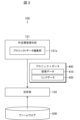
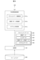
- FIG. 1 is a conceptual diagram showing the configuration of a data providing device according to Embodiment 1.
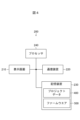
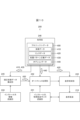
- FIG. Conceptual diagram showing functions of the data providing device according to Embodiment 1 1 is a conceptual diagram showing the configuration of a programmable display device according to Embodiment 1.
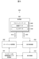
- FIG. 1 is a conceptual diagram showing functions of a programmable display device according to Embodiment 1.
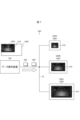
- FIG. 4 is a conceptual diagram showing a mode of autofit processing according to the first embodiment
- FIG. 11 is a conceptual diagram showing one aspect of the module arrangement pattern according to the second embodiment;
- FIG. 11 is a conceptual diagram showing another aspect of the module arrangement pattern according to the second embodiment;
- FIG. 11 is a conceptual diagram showing still another aspect of the module arrangement pattern according to the second embodiment;
- Conceptual diagram showing functions of a data providing device according to Embodiment 2 Conceptual diagram showing functions of a programmable display device according to Embodiment 2
- FIG. 11 is a conceptual diagram showing one mode of display on a display screen according to Embodiment 2
- FIG. 11 is a conceptual diagram showing another mode of display on the display screen according to the second embodiment;
- Flowchart of setup processing according to Embodiment 2 Conceptual diagram showing functions of a data providing device according to Embodiment 3
- the programmable display system 300 includes a plurality of programmable displays 200A, 200B, and 200C, and a communication line CL for each of the programmable displays 200A, 200B, and 200C. and one data providing device 100 communicably connected.
- Each of the programmable displays 200A, 200B, and 200C has a display screen 210 having pixels arranged vertically and horizontally.
- the physical screen sizes of the display screens 210 of the programmable displays 200A, 200B, 200C are different from each other.
- the physical screen size of the display screen 210 of the programmable display 200A is 640 ⁇ 480 pixels.
- the physical screen size of display screen 210 of programmable display 200B is 1280 ⁇ 768 pixels.
- the physical screen size of display screen 210 of programmable display 200C is 1920 ⁇ 1080 pixels.
- each of the programmable displays 200A, 200B, and 200C is referred to as the programmable display 200 when there is no need to distinguish between the programmable displays 200A, 200B, and 200C.
- the programmable display 200 functions as a human-machine interface for a programmable logic controller that controls equipment (not shown). Through the display screen 210 of the programmable display device 200, the user can give an operation command to the equipment and check the operation status of the equipment.
- the data providing device 100 provides project data 400 including image data to be displayed on the display screen 210 of each programmable display 200, and firmware 500 that defines the operation of the programmable display 200. and provide.
- image data refers to data representing an image displayed on the display screen 210. Further, “the image data is displayed on the display screen 210 ” means that the image represented by the image data is displayed on the display screen 210 .
- the data providing device 100 also serves as a project data creation support device that assists the user in creating the project data 400 .
- the physical screen sizes of the display screens 210 of the programmable displays 200A, 200B, and 200C are different from each other. For this reason, conventionally, even if the content of the image data to be provided to the programmable displays 200A, 200B, and 200C is the same, the image data is displayed in an appropriate size on the display screen 210 of each of the programmable displays 200A, 200B, and 200C. In order to be displayed, it was necessary to provide separate image data, ie separate project data 400, for each of the programmable displays 200A, 200B, 200C.
- the project data 400 and the firmware 500 provided by the data providing device 100 to the programmable displays 200A, 200B, and 200C We adopted a configuration that can be used in common.
- the configuration of the programmable display system 300 will be specifically described below.
- the data providing device 100 includes a storage device 110 that stores the previously described project data 400 and firmware 500 that are shared.
- the storage device 110 also stores a data providing program 111 that defines the functions of the data providing device 100 .
- the data providing device 100 also includes a processor 120 that executes the data providing program 111 .
- the creation environment providing function for providing the user with a creation environment for creating the project data 400, and the firmware 500 for transferring the project data 400 created using the creation environment.
- a transmission function is implemented to transmit to each programmable display 200 together with the .
- the data providing device 100 also includes an input device 130 for inputting various data when the user creates the project data 400, and a display device 140 for displaying image data included in the project data 400 during or after creation. and
- the input device 130 and the display device 140 constitute a GUI (Graphical User Interface).
- the data providing device 100 also includes a communication device 150 that communicates with the outside.
- the communication device 150 is connected to the communication line CL shown in FIG. 1 and responsible for transmitting project data 400 and firmware 500 to each programmable display 200 .
- the data providing device 100 has the function of a creation environment providing unit 121 that provides the creation environment for creating the project data 400 to the user.
- this function is an example of a creation environment providing function for providing a creation environment to the user.
- the creation environment providing unit 121 includes a project data editing unit 121a that provides an environment for editing the project data 400 to the user.
- editing of the project data 400 means editing of the image data itself included in the project data 400, and image data showing how to transition images on the display screen 210 of the programmable display device 200 shown in FIG. Including editing associations.
- the user creates the project data 400 using the input device 130 and display device 140 shown in FIG. 2 under the creation environment provided by the creation environment provision unit 121.
- the created project data 400 is saved in the storage device 110 as shown in FIG.
- the project data 400 includes a plurality of image data 410 each representing an image to be displayed on the display screen 210 of the programmable display device 200, and link data 420 defining the association between the image data 410.
- the data providing device 100 also has a function of a transmission section 122 that transmits the project data 400 created using the above creation environment together with the firmware 500 to each programmable display device 200 .
- This function is an example of a transmission function that transmits project data 400 and firmware 500 to each programmable display device 200 . It is assumed that the firmware 500 is prepared in advance in the storage device 110 as shown in FIG.
- sending together means sending both the project data 400 and the firmware 500, and the project data 400 and the firmware 500 do not necessarily need to be sent at the same time. In other words, there may be a time lag between the transmission of the firmware 500 and the transmission of the project data 400 .
- each programmable display device 200 that acquires the project data 400 and the firmware 500 from the transmission unit 122 will be described.
- the programmable display device 200 communicates with a programmable logic controller (not shown) and the data providing device 100 in addition to the already-described display screen 210 that constitutes a touch screen. It comprises a communication device 220 for communication and a storage device 230 in which project data 400 and firmware 500 are stored.
- the project data 400 and firmware 500 stored in the storage device 230 have been transmitted by the transmission section 122 shown in FIG.
- Programmable display 200 also includes processor 240 that executes firmware 500 stored in storage device 230 .
- a state in which the firmware 500 is stored in the storage device 230 and the processor 240 executes the firmware 500 is referred to as the firmware 500 being installed.
- the programmable display device 200 has the function of an acquisition unit 246 that acquires the project data 400.
- Acquisition unit 246 acquires project data 400 from data providing apparatus 100 shown in FIG. 3 together with firmware 500 shown in FIG.
- the programmable display device 200 also has a function of an installation destination physical screen size recognition unit 241 that recognizes the physical screen size of the display screen 210 of the programmable display device 200 (hereinafter referred to as installation destination physical screen size).
- This function is an example of an installation destination physical screen size recognition function for recognizing the installation destination physical screen size.
- the programmable display device 200 also has an auto-fit processing unit that performs auto-fit processing on the image data 410 included in the project data 400 based on the installation destination physical screen size recognized by the installation destination physical screen size recognition unit 241. 242 functions. Note that this function is an example of an autofit processing function that performs autofit processing.
- the data screen size which is the screen size represented by the image data 410
- the data screen size is adjusted under the condition that the data screen size is brought closer to the installation destination physical screen size. is a process for enlarging or reducing the
- the programmable display device 200 also has the function of a display control unit 243 that displays the image data 410 that has undergone autofit processing on the display screen 210 .
- this function is an example of a display control function for displaying the image data 410 on the display screen 210 .
- the display control unit 243 also controls the transition of images displayed on the display screen 210 according to the link data 420 included in the project data 400 .
- the installation destination physical screen size recognition unit 241, the autofit processing unit 242, and the display control unit 243 are realized by executing the firmware 500 acquired by the acquisition unit 246 by the processor 240 shown in FIG. be done. That is, the firmware 500 shown in FIG. 4 provides each function of an installation destination physical screen size recognition unit 241, an autofit processing unit 242, and a display control unit 243 to the programmable display device 200 in which the firmware 500 is installed. make it happen.
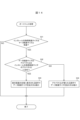
- FIG. 6 shows the operation
- the creation environment providing unit 121 of the data providing device 100 provides the user with a creation environment for creating the project data 400 in order to assist the user in creating the project data 400 (step S11). ).
- Project data 400 created by the user is stored in storage device 110 .
- the transmission unit 122 of the data providing device 100 transmits the project data 400 created by the user to each programmable display device 200 together with the firmware 500 prepared in advance in the storage device 110 (step S12).
- this step S12 is an example of a data transmission step for transmitting common project data 400 and common firmware 500 to a plurality of programmable displays 200.
- each programmable display device 200 first, the firmware 500 acquired from the transmission unit 122 of the data providing device 100 is installed (step S13). As a result, the programmable display device 200 is provided with functions of an installation destination physical screen size recognition unit 241 , an autofit processing unit 242 , and a display control unit 243 .
- this step S13 is an example of a firmware installation step in which the firmware 500 is installed in each of the plurality of programmable displays 200 that have acquired the common firmware 500.
- the installation destination physical screen size recognition unit 241 of the programmable display device 200 recognizes the installation destination physical screen size, which is the screen size of the display screen 210 of the programmable display device 200 (step S14).
- step S15 the image data 410 included in the project data 400 acquired from the transmission unit 122 of the data providing device 100 is subjected to autofit processing by the autofit processing unit 242 of the programmable display device 200.
- the autofit processing unit 242 compares the installation destination physical screen size recognized by the installation destination physical screen size recognition unit 241 with the data screen size of the image data 410 included in the project data 400. (Step S151).
- step S151 when the data screen size is different from the physical screen size of the installation destination (step S151; YES), the autofit processing unit 242 adjusts all the image data 410 included in the project data 400. Enlargement or reduction is performed so that the data screen size of is brought closer to the installation destination physical screen size (step S152). On the other hand, when the data screen size matches the physical screen size of the installation destination (step S151; NO), the autofit processing unit 242 neither enlarges nor reduces the data screen size of the image data 410.
- the display control unit 243 causes the display screen 210 to display the image data 410 that has undergone the above autofit processing (step S16). Further, in step S16, the display control unit 243 transitions the image displayed on the display screen 210 according to the link data 420 included in the project data 400 in accordance with the user's operation on the touch screen configured by the display screen 210. It also controls the
- step S11 A specific example of autofit processing will be described with reference to FIG. Assume that the data screen size of the original image data 410 created by the user using the data providing apparatus 100 in step S11 is 1280 ⁇ 768 pixels.
- the physical screen size SRA of the display screen 210 of the programmable display 200A is 640 ⁇ 480 pixels, which is smaller than the data screen size of the original image data 410. Therefore, even if the original image data 410 is displayed as it is on the display screen 210 of the programmable display device 200A, only part of the image data 410 can be displayed.
- step S152 the programmable display 200A reduces the data screen size of the original image data 410 to 640 ⁇ 480 pixels, which is equal to the installation destination physical screen size.
- step S16 the entire image data 410 after auto-fit processing is displayed over the entire display screen 210 of the programmable display device 200A.
- the physical screen size SRC of the display screen 210 of the programmable display 200C is 1920 ⁇ 1080 pixels, which is larger than the data screen size of the original image data 410. For this reason, even if the original image data 410 is displayed as it is on the display screen 210 of the programmable display device 200C, a margin will occur.
- the programmable display device 200C expands the data screen size of the original image data 410 to 1920 ⁇ 1080 pixels, which is equal to the installation destination physical screen size, in step S152.
- the entire image data 410 after auto-fit processing is displayed over the entire display screen 210 of the programmable display device 200C.
- the physical screen size of the display screen 210 of the programmable display device 200B is 1280 ⁇ 768 pixels, which is equal to the data screen size of the original image data 410. Therefore, the result of determination in step S151 is "NO", and the original image data 410 is displayed on the display screen 210 as it is in step S16.
- the firmware 500 causes the programmable display device 200 to implement the function of the autofit processing section 242 . For this reason, even if it is necessary to set up a plurality of programmable displays 200 with different physical screen sizes, the data screen size of the image data 410 is set in the data providing device 100 for each programmable display 200 to which it is sent. Processing to change is unnecessary, and the project data 400 to be transmitted to the programmable display device 200 can be shared.
- the firmware 500 causes the programmable display device 200 to realize the function of the installation destination physical screen size recognition unit 241 . Therefore, even if it is necessary to set up a plurality of programmable display devices 200 having different physical screen sizes, there is no need to prepare individual firmware 500 for each programmable display device 200 of the destination.
- the firmware 500 transmitted to the display device 200 can be shared.
- the project data 400 and firmware 500 to be transmitted to the programmable displays 200 can be shared. Therefore, the setup of the programmable display 200 can be easily performed.
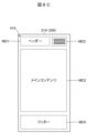
- FIG. 8A shows the configuration of an image displayed on display screen 210 of programmable display 200 .
- image data 410 represents an image composed of a plurality of modules MD1, MD2, MD3, MD4 and MD5.
- the module MD1 is a header that is usually placed at the top of the image and includes character data representing the contents of this image, various logos, dates, and times.
- the module MD2 is a navigation that represents the history of screen transitions.
- the module MD3 is main content including an icon for giving a control command to the device and a graph display area representing the operating state of the device.
- the module MD4 is a sidebar containing icons representing transition destinations of the next screens.
- the module MD5 is a footer that is normally placed at the bottom of the image and includes character data representing standard information and a site map that provides a bird's-eye view of the transition destination of the image.
- the pattern of arrangement of the modules MD1 to MD5 in the image is changed according to the model of the programmable display device 200.
- the types of the programmable display device 200 include a portable tablet, a personal computer that has a display screen 210 larger than the tablet and is placed exclusively fixedly, and a personal computer that is smaller than the tablet.
- a smartphone having a display screen 210 is illustrated.
- FIG. 8A shows the display of the display screen 210 when the model of the programmable display 200 is a personal computer.
- the image displayed on the display screen 210 has a configuration in which a plurality of some selected from the modules MD1 to MD5, specifically, the modules MD3 and MD4 are arranged in the horizontal direction.
- FIG. 8B shows the display on the display screen 210 when the model of the programmable display device 200 is a tablet.
- the image displayed on the display screen 210 has a configuration in which all the modules MD1 to MD5 are arranged only in the vertical direction.
- FIG. 8C shows the display on the display screen 210 when the model of the programmable display device 200 is a smart phone.
- the module MD2 representing the screen transition history is displayed as an icon for displaying the screen transition history as a pull-down menu.
- the display of the module MD4 shown in FIGS. 8A and 8B is omitted.
- the image displayed on the display screen 210 has a configuration in which at least one of the modules MD1 to MD5 is iconized and at least one of the modules MD1 to MD5 is omitted. have at least one of the following configurations:
- Creation environment providing unit 121 further has a function of layout pattern definition unit 121b for defining patterns of layout of modules MD1 to MD5 described above for each model of programmable display device 200.
- This function is an example of a layout pattern definition function that accepts definitions of layout patterns of the modules MD1 to MD5.
- the image data 410 itself including the modules MD1-MD5 is created by the user using the project data editor 121a.
- the layout pattern definition unit 121b accepts a definition of layout patterns of the modules MD1 to MD5 for each model of the programmable display 200 from the user. Then, the arrangement pattern definition unit 121b includes the arrangement pattern definition data 430 representing the definition made by the user in the project data 400.
- FIG. 1 A layout pattern definition unit 121b accepts a definition of layout patterns of the modules MD1 to MD5 for each model of the programmable display 200 from the user. Then, the arrangement pattern definition unit 121b includes the arrangement pattern definition data 430 representing the definition made by the user in the project data 400.
- the user uses the arrangement pattern definition unit 121b to adopt the arrangement shown in FIG. 8A for the modules MD1 to MD5 when the model of the programmable display 200 is a personal computer, 8B, and if the model of the programmable display device 200 is a smart phone, the modules MD1 to MD5 take the arrangement shown in FIG. 8C.
- the layout pattern definition data 430 representing the definition of the correspondence between the model of the programmable display device 200 and the layout pattern of the modules MD1 to MD5 is included in the project data 400 by the layout pattern definition unit 121b.
- the creation environment providing unit 121 also has a function of an option specifying unit 121c that accepts from the user the specification of options for the autofit processing performed on the programmable display device 200. It should be noted that this function is an example of an option designation function that accepts the designation of an option.
- option indicates how to enlarge or reduce the image data 410 in the autofit process performed by the programmable display device 200.
- the option specifying unit 121c accepts the selection of a desired option from a plurality of option choices from the user as the option specification.
- the options include (i) an option for enlarging or reducing the image data while maintaining the aspect ratio of the data screen size represented by the image data 410 (hereinafter referred to as a fixed aspect ratio option). ) and (ii) the image data 410 under the condition that the image data 410 is displayed in the aspect ratio of the physical screen size of the programmable display device 200 on which the programmable display device 200 is installed and is displayed on the entire display screen 210 of the programmable display device 200. (iii) an option indicating that the image data 410 should be displayed on the display screen 210 as it is without enlarging or reducing the image data 410; option (hereinafter referred to as data screen size retention option), and .
- option specifying unit 121c includes, in the project data 400, option data 440 representing options specified by the user among the fixed aspect ratio option, full screen display option, and data screen size retention option.
- the project data 400 created using the creation environment providing unit 121 includes the image data 410 and the link data 420 described above, as well as the layout pattern definition data 430 and the option data 440. and are further included.
- Such project data 400 is transmitted to programmable display 200 by transmitter 122 together with firmware 500 .
- the programmable display device 200 further includes an installation destination model recognition unit 244 and a confirmed image data construction unit 245 .
- the functions of the installation destination model recognition unit 244 and the confirmed image data configuration unit 245 are similar to the functions of the installation destination physical screen size recognition unit 241, the autofit processing unit 242, and the display control unit 243 described above. is implemented by firmware 500 installed in the
- the functions of the installation destination model recognition unit 244 and the confirmed image data configuration unit 245 will be specifically described below.
- the installation target model recognition unit 244 recognizes the model of the programmable display device 200 provided with the installation target model recognition unit 244 (hereinafter referred to as the installation target model). Specifically, the installation target model recognition unit 244 recognizes which of the above-described tablet, personal computer, and smartphone the installation target model is.
- the installation destination model recognition unit 244 is an example of an installation destination model recognition function for recognizing the installation destination model.
- the finalized image data configuration unit 245 uses the image data 410 and the layout pattern definition data 430 included in the project data 400 acquired by the programmable display device 200 to configure finalized image data 450 according to the installation destination model.
- the confirmed image data configuration unit 245 is an example of a confirmed image data configuration function that configures the confirmed image data 450 .
- the arrangement pattern definition data 430 is data that associates the model of the programmable display device 200 with the arrangement pattern of the modules MD1 to MD5.
- the confirmed image data 450 is the image data 410 representing an image in which the layout of the modules MD1 to MD5 has been decided according to the definition of the layout pattern definition data 430.
- the confirmed image data 450 represents an image in which the modules MD1 to MD5 described above are arranged in a pattern corresponding to the installation destination model defined in the arrangement pattern definition data 430.
- FIG. Such finalized image data 450 is created corresponding to each image data 410 included in the project data 400 .
- the image represented by the original image data 410 included in the project data 400 at the time of acquisition from the data providing device 100 is a specific model of the programmable display device 200 among tablets, personal computers, and smartphones (hereinafter , is referred to as an initially designated model).
- the data screen size of the original image data 410 is fixed. That is, the position and size of each of the modules (hereinafter referred to as initially defined modules) MD1 to MD5 included in the image represented by the original image data 410 are fixed in the image.
- the layout pattern definition data 430 includes not only information on how to change the position in the image of each of the initial definition modules MD1 to MD5 when the installation destination model is other than the initially designated model, It is assumed that the size of each of the initial definition modules MD1-MD5 is to be expanded or reduced in terms of aspect ratio.
- the installation destination model matches the initially specified model, the confirmed image data 450 matches the original image data 410 .
- the size of each of the initial definition modules MD1-MD5 is fixed, and the arrangement pattern definition data 430 includes the aspect ratio for enlarging or reducing the size of each of the initial definition modules MD1-MD5. information is also included. Therefore, the data screen size of the confirmed image data 450 is naturally determined.
- the autofit processing unit 242 subjects the confirmed image data 450 having a fixed data screen size, which is configured by the confirmed image data configuration unit 245 as described above, to autofit processing. Also, the autofit processing unit 242 performs autofit processing in a manner represented by the option data 440 included in the project data 400 .
- the autofit processing unit 242 maintains the aspect ratio of the data screen size represented by all of the finalized image data 450, and Bring the data screen size of the data 450 close to the physical screen size of the installation destination.
- the autofit processing unit 242 matches the data screen size represented by all the confirmed image data 450 with the physical screen size of the installation destination.
- the autofit processing unit 242 does not enlarge or reduce any of the confirmed image data 450 when the option data 440 represents the data screen size retention option described above. In this case, all the confirmed image data 450 are displayed on the display screen 210 as they are.
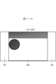
- FIG. 11A exemplifies the display of the display screen 210 when the option data 440 represents the fixed aspect ratio option described above. Since the aspect ratio of the finalized image data 450 is maintained, when the aspect ratio of the finalized image data 450 differs from the aspect ratio of the display screen 210, the image IMA represented by the enlarged or reduced finalized image data 450 and the display A blank area BA is displayed between the edges of the screen 210 . However, since the aspect ratio of the finalized image data 450 is maintained, there is an advantage that the image IMA is not distorted.
- FIG. 11B illustrates the display of the display screen 210 when the option data 440 represents the full screen display option described above.
- the image IMB represented by the enlarged or reduced confirmed image data 450 is displayed on the entire display screen 210 . If the aspect ratio of the screen size represented by the finalized image data 450 is different from the aspect ratio of the display screen 210, the image IMB will be distorted by being stretched vertically or horizontally. However, since the image IMB is displayed on the entire display screen 210, there is an advantage that the image IMB is large and easy to see.
- FIG. 12 shows the operation
- step S11 in which the creation environment providing unit 121 provides the creation environment, the user not only creates the image data 410 and the link data 420 using the project data editing unit 121a, but also creates the arrangement pattern definition unit. 121b to create layout pattern definition data 430 for each image data 410, and option data 440 to create option data 440 using the option specifying unit 121c.
- Common project data 400 including image data 410, link data 420, arrangement pattern definition data 430, and option data 440 created in this manner is sent to programmable display device 200 together with common firmware 500. (step S12).
- the programmable display device 200 includes the installation destination physical screen size recognition unit 241, the autofit processing unit 242, and the display control unit 243.
- each function of an installation destination model recognition unit 244 and a confirmed image data construction unit 245 is provided.
- the installation destination model recognition unit 244 recognizes the installation destination model, which is the model of the programmable display device 200 (step S21). Specifically, the installation target model recognition unit 244 recognizes which of the above-described tablet, personal computer, and smartphone the installation target model is.
- the finalized image data configuration unit 245 uses the pattern corresponding to the installation destination model defined in the layout pattern definition data 430 included in the project data 400.
- Defined image data 450 representing an image in which modules MD1-MD5 are arranged is constructed (step S22).
- the confirmed image data 450 is configured corresponding to each of the image data 410 included in the project data 400 .
- each fixed image data 450 is subjected to autofit processing by the autofit processing unit 242 (step S15). ).
- the autofit processing unit 242 first compares the installation destination physical screen size recognized by the installation destination physical screen size recognition unit 241 with the data screen size, which is the screen size represented by the confirmed image data 450 . .
- the auto-fit processing unit 242 adjusts the data screen size of the finalized image data 450 under the condition that the data screen size of the finalized image data 450 is brought closer to the physical screen size of the installation destination. Enlarge or reduce screen size. However, this enlargement or reduction is performed in a manner specified in option data 440 included in project data 400 .
- option data 440 represents the fixed aspect ratio option, as shown in FIG. Close to the physical screen size of the installation destination.
- the option data 440 represents the full-screen display option described above
- the data screen size is made to match the physical screen size of the installation destination, as shown in FIG. 11B.
- the option data 440 represents the data screen size retention option described above, neither enlargement nor reduction of the data screen size is performed.
- the display control unit 243 causes the display screen 210 to display the finalized image data 450 that has undergone the autofit process (step S16). Further, in step S16, the display control unit 243 transitions the image displayed on the display screen 210 according to the link data 420 included in the project data 400 in accordance with the user's operation on the touch screen configured by the display screen 210. It also controls the
- the finalized image data configuration unit 245 in each programmable display device 200, the finalized image data configuration unit 245 generates a finalized image representing an image in which the modules MD1 to MD5 are arranged in a pattern corresponding to the installation destination model. Construct image data 450 . That is, the arrangement of the modules MD1 to MD5 is automatically adjusted for each model of the programmable display device 200. FIG. Therefore, an easy-to-see image suitable for the model of the programmable display device 200 can be provided.
- the firmware 500 causes the programmable display device 200 to realize the function of the installation destination model recognition unit 244 . Therefore, the user of the data providing device 100 does not need to specify the model of each programmable display 200 to which the project data 400 is sent. Moreover, even when the models of the plurality of programmable displays 200 that are destinations are different from each other, the project data 400 and the firmware 500 that are transmitted to the programmable displays 200 can be shared.
- the method of enlarging or reducing the finalized image data 450 in the auto-fitting process performed by the programmable display device 200 can be designated as an option in the data providing device 100 in advance. Therefore, an easy-to-see image suitable for the contents of the project data 400 can be displayed on the programmable display device 200 . In this way, the fact that the option can be specified also contributes to an improvement in the viewability of the image displayed on the programmable display 200 .
- FIG. 13 shows the configuration of the data providing device 100 according to this embodiment.
- the data providing apparatus 100 according to the present embodiment further has the function of the simulation section 123 shown in FIG. 13 in addition to the creation environment providing section 121 and the transmission section 122 shown in FIG. Note that this function is an example of a simulation function for checking the display of the image data 410 .
- the simulation unit 123 is also realized by the data providing program 111 shown in FIG. 2, like the creation environment providing unit 121 and the transmitting unit 122 shown in FIG.
- the configuration of the simulation unit 123 will be specifically described below with reference to FIG. It is assumed that the project data 400 including the image data 410, the link data 420, the layout pattern definition data 430, and the option data 440 has already been created using the creating environment providing unit 121 shown in FIG.
- the simulation unit 123 is for confirming the display on the display screen 210 of the programmable display device 200 of the image data 410 created using the creation environment.
- the simulation unit 123 has the function of a virtual physical screen size specifying unit 123a that accepts from the user the specification of the virtual physical screen size representing the physical screen size of the programmable display device 200 to be installed. Note that this function is an example of a virtual physical screen size specification function that accepts specification of a virtual physical screen size.
- the user uses the input device 130 shown in FIG. 2 to specify the virtual physical screen size representing the assumed physical screen size of the installation destination of the programmable display device 200 of the transmission destination in the virtual physical screen size designating section 123a.
- the simulation unit 123 also has a function of a virtual model specification unit 123b that accepts specification of a virtual model representing the installation destination model of the programmable display device 200 from the user. It should be noted that this function is an example of a virtual machine designation function that accepts designation of a virtual machine.
- the user uses the input device 130 shown in FIG. 2 to designate a virtual machine model indicating an assumed installation destination machine model of the programmable display device 200 of the transmission destination in the virtual machine model specifying section 123b.
- the simulation unit 123 configures the simulation final image data 460 corresponding to the specified virtual model using the arrangement pattern definition data 430 and the image data 410 including the modules MD1 to MD5 described above. It has the function of the image data construction unit 123c. It should be noted that this function is an example of the function of forming the finalized image data for simulation that constitutes the finalized image data for simulation 460 .
- the simulation fixed image data 460 represents an image in which the modules MD1 to MD5 are arranged in a pattern corresponding to the virtual model defined in the arrangement pattern definition data 430 .
- Such simulation final image data 460 is created corresponding to each of the image data 410 included in the project data 400 .
- the simulation unit 123 also has the function of a simulation autofit processing unit 123d that performs the same simulation autofit processing as the autofit processing described above on the simulation finalized image data 460 . Note that this function is an example of the simulation autofit processing function that performs the simulation autofit processing.
- the simulation autofit processing unit 123d first determines the simulation data screen size, which is the screen size represented by the simulation fixed image data 460, and the virtual physical data screen size specified by the user in the virtual physical screen size specifying unit 123a. Compare with screen size.
- the simulation autofit processing unit 123d adjusts the simulation data screen size under the condition that the simulation data screen size is brought close to the virtual physical screen size. Increase or decrease size. The enlargement or reduction is performed according to options represented by option data 440 .
- the simulation autofit processing unit 123d changes the simulation data screen size while maintaining the aspect ratio of the simulation data screen size. Close to the virtual physical screen size. Further, the simulation autofit processing unit 123d matches the simulation data screen size with the virtual physical screen size when the option data 440 represents the full screen display option described above.
- the simulation autofit processing unit 123d changes the simulation data screen size. Do not scale up or scale down.
- the simulation unit 123 also has a function of a simulation display control unit 123e that controls the display device 140 to display the simulation finalized image data 460 subjected to the above-described simulation autofit processing. Note that this function is an example of a simulation display control function that controls the display of the finalized image data for simulation.
- the simulation display control unit 123e causes the display device 140 to display a frame line representing the virtual physical screen size, and then displays the simulation finalized image data 460 that has undergone the simulation autofit process within the frame line. Let The simulation display control unit 123e also performs control for transitioning the image displayed on the display device 140 according to the link data 420 according to the user's operation using the input device 130 shown in FIG.
- the user of the data providing device 100 confirms in advance the display mode of the image data 410 on the display screen 210 of the programmable display device 200 on the display device 140 of the data providing device 100. be able to.
- the user of the data providing device 100 can confirm the validity of the project data 400 including the image data 410, the link data 420, the layout pattern definition data 430, and the option data 440 created by the user in advance by simulation. . Therefore, the user of the data providing device 100 can review the project data 400 created by himself/herself as necessary and then transmit it to the programmable display device 200 .
- the option designating section 121c shown in FIG. 9 is used to designate options for autofit processing in advance by the user.
- a configuration in which the specification of this option is omitted may be adopted. A specific example will be described below.
- Fig. 14 shows a flowchart of autofit processing in which option specification can be omitted.
- the autofit processing shown in FIG. 14 is executed by the autofit processing section 242 of the programmable display 200 instead of step S15 of FIG.
- the auto-fitting process according to this embodiment will be specifically described below.
- the autofit processing unit 242 of the programmable display device 200 compares the installation destination physical screen size recognized by the installation destination physical screen size recognition unit 241 with the data screen size of the confirmed image data 450 (step S31).
- step S31 If the data screen size is different from the installation destination physical screen size (step S31; YES), the autofit processing unit 242 makes the aspect ratio represented by the data screen size approximate the aspect ratio represented by the installation destination physical screen size. It is determined whether or not (step S32).
- the autofit processing unit 242 calculates the aspect ratio represented by the data screen size. (hereinafter referred to as the data aspect ratio) and the aspect ratio represented by the physical screen size of the installation destination (hereinafter referred to as the physical aspect ratio) determines whether or not the absolute value of the difference is equal to or less than a predetermined threshold. do.
- the threshold represents the maximum value at which the data aspect ratio and the physical aspect ratio can be said to be close.
- step S32 When the absolute value of the difference between the data aspect ratio and the physical aspect ratio is equal to or less than the threshold, it can be said that the data aspect ratio and the physical aspect ratio are close to each other (step S32; YES). In this case, even if the finalized image data 450 is displayed with an aspect ratio equal to the physical aspect ratio, distortion of the displayed image is small.
- the auto-fit processing unit 242 adjusts the data screen size of the confirmed image data 450 under the condition that the confirmed image data 450 has an aspect ratio equal to the physical aspect ratio and is displayed on the entire display screen 210. Enlargement or reduction is performed (step S33).
- step S32 if the absolute value of the difference between the data aspect ratio and the physical aspect ratio exceeds the threshold, it cannot be said that the data aspect ratio and the physical aspect ratio are close to each other (step S32; NO). In this case, if the finalized image data 450 is displayed with an aspect ratio equal to the physical aspect ratio, there is a concern that the displayed image will be greatly distorted.
- the autofit processing unit 242 enlarges or reduces the screen size of the finalized image data 450 to bring it closer to the physical screen size of the installation destination while maintaining the aspect ratio of the finalized image data 450 (step S34).
- step S31 If the data screen size matches the installation destination physical screen size in step S31 (step S31; NO), or after step S33 or step S34, the process proceeds to step S16 in FIG.
- Embodiments 1-4 have been described above. Variations described below are also possible.
- the option specifying section 121c may be omitted.
- project data 400 does not include option data 440 .
- the autofit processing unit 242 enlarges or reduces the data screen size of the finalized image data 450 in a manner predetermined in the firmware 500 .
- the layout pattern definition unit 121b, the installation destination model recognition unit 244, and the confirmed image data configuration unit 245 may be omitted.
- the project data 400 does not include the layout pattern definition data 430 .
- the autofit processing unit 242 enlarges or reduces the data screen size of the image data 410 included in the project data 400 in a manner determined in the option data 440 .
- FIG. 1 illustrates a configuration in which a plurality of programmable displays 200 are communicatively connected to the data providing device 100.
- the project data 400 and the firmware 500 may be simultaneously transmitted from the data providing device 100 to multiple programmable displays 200 . Also, there may be a time lag between sending project data 400 and firmware 500 to one programmable display 200 and sending project data 400 and firmware 500 to another programmable display 200 . Also, the project data 400 and the firmware 500 may be transmitted to one programmable display device 200 .
- the project data 400 may be updated. In that case, no retransmission of firmware 500 to that programmable display 200 is necessary.
- the data providing device 100 only has to transmit the updated project data 400 to the programmable display 200 .
- steps S14-S16 shown in FIG. 6 are executed again for the updated project data 400.
- the data providing device 100 can be realized by an existing computer. That is, by installing the data providing program 111 shown in FIG. 2 in a computer, the computer can function as the data providing device 100 .
- the data providing program 111 may be distributed via a communication network, or stored in a non-temporary computer-readable recording medium for distribution.
- the data providing device 100 transmits the project data 400 to a supervisory control system (SCADA: Supervisory Control and Data Acquisition) (not shown) that monitors the programmable display device 200. good.
- SCADA Supervisory Control and Data Acquisition
- the data providing device 100 may also include a data conversion tool that converts various data created for the programmable display 200 into data that can be used in the monitoring control system.
- the screen size of the image data 410 may be set so as not to be changed by the data conversion tool.
Landscapes
- Physics & Mathematics (AREA)
- General Physics & Mathematics (AREA)
- Engineering & Computer Science (AREA)
- Automation & Control Theory (AREA)
- User Interface Of Digital Computer (AREA)
- Testing And Monitoring For Control Systems (AREA)
- Controls And Circuits For Display Device (AREA)
- Programmable Controllers (AREA)
- Digital Computer Display Output (AREA)
Abstract
Description
プログラマブル表示器の表示画面に表示される画像データを含むプロジェクトデータを、前記プログラマブル表示器に提供するコンピュータに、
前記プロジェクトデータを作成する作成環境を提供する作成環境提供機能と、
前記作成環境を用いて作成された前記プロジェクトデータを、前記プログラマブル表示器の動作を規定するファームウエアと一緒に、前記プログラマブル表示器に送信する送信機能と、
を実現させ、
前記ファームウエアは、
該ファームウエアがインストールされた前記プログラマブル表示器の前記表示画面の画面サイズであるインストール先物理画面サイズを認識するインストール先物理画面サイズ認識機能と、
該プログラマブル表示器が前記コンピュータから取得した前記プロジェクトデータに含まれる前記画像データが表す画面サイズであるデータ画面サイズが、前記インストール先物理画面サイズと相違する場合に、前記データ画面サイズが前記インストール先物理画面サイズに近づけられる条件で、前記データ画面サイズを拡大又は縮小するオートフィット処理を行うオートフィット処理機能と、
前記オートフィット処理機能によって前記オートフィット処理が施された前記画像データを該プログラマブル表示器の前記表示画面に表示させる表示制御機能と、
を該プログラマブル表示器に実現させる。
図1に示すように、本実施の形態に係るプログラマブル表示システム300は、複数台のプログラマブル表示器200A、200B、200Cと、それらプログラマブル表示器200A、200B、200Cの各々に通信回線CLを介して通信可能に接続された1台のデータ提供装置100とを備える。
上記実施の形態1において、プログラマブル表示器200の表示画面210における画像データ410の表示の態様を、予めデータ提供装置100において具体的に指定可能な構成を採ってもよい。以下、その具体例を述べる。
上記実施の形態2において、データ提供装置100からプログラマブル表示器200へのプロジェクトデータ400及びファームウエア500の送信の前に、プログラマブル表示器200の表示画面210における画像データ410の表示の態様を、データ提供装置100において確認可能な構成を採ってもよい。以下、その具体例を述べる。
上記実施の形態2では、図9に示すオプション指定部121cを用いて、オートフィット処理に対するオプションをユーザが予め指定する構成を示した。このオプションの指定が省略される構成を採ってもよい。以下、その具体例を述べる。
Claims (9)
- プログラマブル表示器の表示画面に表示される画像データを含むプロジェクトデータを、前記プログラマブル表示器に提供するコンピュータに、
前記プロジェクトデータを作成する作成環境を提供する作成環境提供機能と、
前記作成環境を用いて作成された前記プロジェクトデータを、前記プログラマブル表示器の動作を規定するファームウエアと一緒に、前記プログラマブル表示器に送信する送信機能と、
を実現させ、
前記ファームウエアは、
該ファームウエアがインストールされた前記プログラマブル表示器の前記表示画面の画面サイズであるインストール先物理画面サイズを認識するインストール先物理画面サイズ認識機能と、
該プログラマブル表示器が前記コンピュータから取得した前記プロジェクトデータに含まれる前記画像データが表す画面サイズであるデータ画面サイズが、前記インストール先物理画面サイズと相違する場合に、前記データ画面サイズが前記インストール先物理画面サイズに近づけられる条件で、前記データ画面サイズを拡大又は縮小するオートフィット処理を行うオートフィット処理機能と、
前記オートフィット処理機能によって前記オートフィット処理が施された前記画像データを該プログラマブル表示器の前記表示画面に表示させる表示制御機能と、
を該プログラマブル表示器に実現させる、
データ提供プログラム。 - 前記作成環境提供機能は、
前記プロジェクトデータに含まれる前記画像データに対する前記オートフィット処理における前記拡大又は前記縮小の仕方を表すオプションの指定を受け付けるとともに、指定された前記オプションを表すオプションデータを前記プロジェクトデータに含めるオプション指定機能、
を有し、
前記オートフィット処理機能は、前記オートフィット処理において、前記プロジェクトデータに含まれる前記オプションデータが表す仕方で、該プロジェクトデータに含まれる前記画像データの前記データ画面サイズの前記拡大又は前記縮小を行う、
請求項1に記載のデータ提供プログラム。 - 前記オプション指定機能は、前記オプションの指定として、複数の前記オプションの選択肢からのいずれかの前記オプションの選択を受け付け、
前記選択肢には、
前記画像データが表す前記データ画面サイズのアスペクト比を保ったまま、該画像データの前記拡大又は前記縮小を行う旨を表す前記オプションと、
前記画像データが、前記プログラマブル表示器の前記インストール先物理画面サイズのアスペクト比で、かつ該プログラマブル表示器の前記表示画面の全域に表示される条件で、該画像データの前記拡大又は前記縮小を行う旨を表す前記オプションと、
が含まれる、請求項2に記載のデータ提供プログラム。 - 前記画像データは、複数のモジュールによって構成される画像を表し、
前記作成環境提供機能は、
前記プログラマブル表示器の機種ごとの、前記画像における前記モジュールの配置のパターンの定義を受け付けるとともに、該定義を表す配置パターン定義データを前記プロジェクトデータに含める配置パターン定義機能、
を有し、
前記ファームウエアは、
該ファームウエアがインストールされた前記プログラマブル表示器の前記機種であるインストール先機種を認識するインストール先機種認識機能と、
該プログラマブル表示器が前記コンピュータから取得した前記プロジェクトデータに含まれる前記画像データを用いて、該プロジェクトデータに含まれる前記配置パターン定義データにおいて定義されている、前記インストール先機種に対応する前記パターンで前記モジュールが配置された前記画像を表す確定画像データを構成する確定画像データ構成機能と、
をさらに前記プログラマブル表示器に実現させ、
前記オートフィット処理機能は、前記確定画像データ構成機能によって構成された前記確定画像データを、前記オートフィット処理の対象とする、
請求項1に記載のデータ提供プログラム。 - 前記作成環境を用いて作成された前記画像データの、前記プログラマブル表示器の前記表示画面における表示を確認するためのシミュレーション機能、
をさらに備え、
前記シミュレーション機能は、
前記プログラマブル表示器の前記インストール先物理画面サイズを表す仮想物理画面サイズの指定を受け付ける仮想物理画面サイズ指定機能と、
前記プログラマブル表示器の前記インストール先機種を表す仮想機種の指定を受け付ける仮想機種指定機能と、
前記作成環境を用いて作成された前記プロジェクトデータに含まれる前記画像データを用いて、該プロジェクトデータに含まれる前記配置パターン定義データにおいて定義されている、前記仮想機種に対応する前記パターンで前記モジュールが配置された前記画像を表すシミュレーション用確定画像データを構成するシミュレーション用確定画像データ構成機能と、
前記シミュレーション用確定画像データが表す画面サイズであるシミュレーション用データ画面サイズが、前記仮想物理画面サイズと相違する場合に、前記シミュレーション用データ画面サイズが前記仮想物理画面サイズに近づけられる条件で、前記シミュレーション用データ画面サイズを拡大又は縮小するシミュレーション用オートフィット処理を行うシミュレーション用オートフィット処理機能と、
前記シミュレーション用オートフィット処理機能によって前記シミュレーション用オートフィット処理が施された前記シミュレーション用確定画像データを表示させる制御を行うシミュレーション用表示制御機能と、
を有する、請求項4に記載のデータ提供プログラム。 - プログラマブル表示器の表示画面に表示される画像データを含むプロジェクトデータを、前記プログラマブル表示器に提供するデータ提供装置であって、
前記プロジェクトデータを作成する作成環境を提供する作成環境提供部と、
前記プログラマブル表示器の動作を規定するファームウエアを記憶する記憶装置と、
前記作成環境を用いて作成された前記プロジェクトデータと、前記記憶装置に記憶されている前記ファームウエアとを、前記プログラマブル表示器に送信する送信部と、
を備え、
前記ファームウエアは、
該ファームウエアがインストールされた前記プログラマブル表示器の前記表示画面の画面サイズであるインストール先物理画面サイズを認識するインストール先物理画面サイズ認識機能と、
該プログラマブル表示器が前記送信部から取得した前記プロジェクトデータに含まれる前記画像データが表す画面サイズであるデータ画面サイズが、前記インストール先物理画面サイズと相違する場合に、前記データ画面サイズが前記インストール先物理画面サイズに近づけられる条件で、前記データ画面サイズを拡大又は縮小するオートフィット処理を行うオートフィット処理機能と、
前記オートフィット処理機能によって前記オートフィット処理が施された前記画像データを該プログラマブル表示器の前記表示画面に表示させる表示制御機能と、
を該プログラマブル表示器に実現させる、
データ提供装置。 - 請求項6に記載のデータ提供装置と、
それぞれ前記データ提供装置に通信回線を介して接続されており、かつ互いの前記表示画面の前記画面サイズが異なる複数台の前記プログラマブル表示器と、
を備え、
前記データ提供装置の前記送信部は、複数台の前記プログラマブル表示器の各々に、共通の前記プロジェクトデータと、共通の前記ファームウエアとを送信する、
プログラマブル表示システム。 - 画像データが表示される表示画面と、
前記画像データを含むプロジェクトデータをファームウエアと一緒にデータ提供装置から取得する取得部と、
を備え、
前記ファームウエアを実行することにより、
前記表示画面の画面サイズであるインストール先物理画面サイズを認識するインストール先物理画面サイズ認識機能と、
前記プロジェクトデータに含まれる前記画像データが表す画面サイズであるデータ画面サイズが、前記インストール先物理画面サイズと相違する場合に、前記データ画面サイズが前記インストール先物理画面サイズに近づけられる条件で、前記データ画面サイズを拡大又は縮小するオートフィット処理を行うオートフィット処理機能と、
前記オートフィット処理機能によって前記オートフィット処理が施された前記画像データを前記表示画面に表示させる表示制御機能と、
を実現する、プログラマブル表示器。 - 互いの表示画面の画面サイズが異なる複数台のプログラマブル表示器と、複数台の前記プログラマブル表示器の各々に通信回線を介して接続されたデータ提供装置とを備えるプログラマブル表示システムにおけるデータ提供方法であって、
前記データ提供装置が、複数台の前記プログラマブル表示器に対して、前記プログラマブル表示器の前記表示画面に表示される画像データを含む共通のプロジェクトデータと、前記プログラマブル表示器の動作を規定する共通のファームウエアとを送信するデータ送信ステップと、
共通の前記ファームウエアを取得した複数台の前記プログラマブル表示器の各々に、該ファームウエアがインストールされるファームウエアインストールステップと、
を含み、
前記ファームウエアは、
該ファームウエアがインストールされた前記プログラマブル表示器の前記表示画面の画面サイズであるインストール先物理画面サイズを認識するインストール先物理画面サイズ認識機能と、
該プログラマブル表示器が前記データ提供装置から取得した前記プロジェクトデータに含まれる前記画像データが表す画面サイズであるデータ画面サイズが、前記インストール先物理画面サイズと相違する場合に、前記データ画面サイズが前記インストール先物理画面サイズに近づけられる条件で、前記データ画面サイズを拡大又は縮小するオートフィット処理を行うオートフィット処理機能と、
前記オートフィット処理機能によって前記オートフィット処理が施された前記画像データを該プログラマブル表示の前記表示画面に表示させる表示制御機能と、
を該プログラマブル表示器に実現させる、
データ提供方法。
Priority Applications (4)
| Application Number | Priority Date | Filing Date | Title |
|---|---|---|---|
| CN202180100075.5A CN117581294B (zh) | 2021-12-03 | 2021-12-03 | 数据提供程序产品、数据提供装置、可编程显示系统、可编程显示器及数据提供方法 |
| DE112021007589.6T DE112021007589T5 (de) | 2021-12-03 | 2021-12-03 | Datenbereitstellungsprogramm, Datenbereitstellungsvorrichtung, programmierbares Anzeigesystem, programmierbare Anzeige und Datenbereitstellungsverfahren |
| JP2022529471A JP7114007B1 (ja) | 2021-12-03 | 2021-12-03 | データ提供プログラム、データ提供装置、プログラマブル表示システム、プログラマブル表示器、及びデータ提供方法 |
| PCT/JP2021/044383 WO2023100337A1 (ja) | 2021-12-03 | 2021-12-03 | データ提供プログラム、データ提供装置、プログラマブル表示システム、プログラマブル表示器、及びデータ提供方法 |
Applications Claiming Priority (1)
| Application Number | Priority Date | Filing Date | Title |
|---|---|---|---|
| PCT/JP2021/044383 WO2023100337A1 (ja) | 2021-12-03 | 2021-12-03 | データ提供プログラム、データ提供装置、プログラマブル表示システム、プログラマブル表示器、及びデータ提供方法 |
Publications (1)
| Publication Number | Publication Date |
|---|---|
| WO2023100337A1 true WO2023100337A1 (ja) | 2023-06-08 |
Family
ID=82740490
Family Applications (1)
| Application Number | Title | Priority Date | Filing Date |
|---|---|---|---|
| PCT/JP2021/044383 Ceased WO2023100337A1 (ja) | 2021-12-03 | 2021-12-03 | データ提供プログラム、データ提供装置、プログラマブル表示システム、プログラマブル表示器、及びデータ提供方法 |
Country Status (4)
| Country | Link |
|---|---|
| JP (1) | JP7114007B1 (ja) |
| CN (1) | CN117581294B (ja) |
| DE (1) | DE112021007589T5 (ja) |
| WO (1) | WO2023100337A1 (ja) |
Citations (7)
| Publication number | Priority date | Publication date | Assignee | Title |
|---|---|---|---|---|
| JP2004191483A (ja) * | 2002-12-09 | 2004-07-08 | Digital Electronics Corp | データ転送装置、データ転送システム、データ転送方法およびデータ転送プログラム |
| JP2008096935A (ja) * | 2006-10-16 | 2008-04-24 | Digital Electronics Corp | 画面作成装置、画面作成プログラムおよびそれを記録した記録媒体 |
| JP2008250962A (ja) * | 2007-03-30 | 2008-10-16 | Hakko Denki Kk | 画面編集装置、そのプログラム |
| JP2013206403A (ja) * | 2012-03-29 | 2013-10-07 | Keyence Corp | 操作手順書作成装置、操作手順書作成方法および操作手順書作成プログラム |
| US20160196805A1 (en) * | 2014-08-15 | 2016-07-07 | Boe Technology Group Co., Ltd. | Display Device, Display System and Display Method |
| JP2018092478A (ja) * | 2016-12-06 | 2018-06-14 | 矢崎総業株式会社 | 作業指示システム |
| WO2021171376A1 (ja) * | 2020-02-25 | 2021-09-02 | 三菱電機株式会社 | 表示制御装置および表示端末 |
Family Cites Families (2)
| Publication number | Priority date | Publication date | Assignee | Title |
|---|---|---|---|---|
| JP5152031B2 (ja) * | 2008-03-24 | 2013-02-27 | ブラザー工業株式会社 | 画像処理装置およびコンピュータプログラム |
| KR102103695B1 (ko) * | 2017-05-19 | 2020-04-23 | 미쓰비시덴키 가부시키가이샤 | 정보 표시 장치, 프로그램 및 정보 표시 방법 |
-
2021
- 2021-12-03 WO PCT/JP2021/044383 patent/WO2023100337A1/ja not_active Ceased
- 2021-12-03 JP JP2022529471A patent/JP7114007B1/ja active Active
- 2021-12-03 CN CN202180100075.5A patent/CN117581294B/zh active Active
- 2021-12-03 DE DE112021007589.6T patent/DE112021007589T5/de active Pending
Patent Citations (7)
| Publication number | Priority date | Publication date | Assignee | Title |
|---|---|---|---|---|
| JP2004191483A (ja) * | 2002-12-09 | 2004-07-08 | Digital Electronics Corp | データ転送装置、データ転送システム、データ転送方法およびデータ転送プログラム |
| JP2008096935A (ja) * | 2006-10-16 | 2008-04-24 | Digital Electronics Corp | 画面作成装置、画面作成プログラムおよびそれを記録した記録媒体 |
| JP2008250962A (ja) * | 2007-03-30 | 2008-10-16 | Hakko Denki Kk | 画面編集装置、そのプログラム |
| JP2013206403A (ja) * | 2012-03-29 | 2013-10-07 | Keyence Corp | 操作手順書作成装置、操作手順書作成方法および操作手順書作成プログラム |
| US20160196805A1 (en) * | 2014-08-15 | 2016-07-07 | Boe Technology Group Co., Ltd. | Display Device, Display System and Display Method |
| JP2018092478A (ja) * | 2016-12-06 | 2018-06-14 | 矢崎総業株式会社 | 作業指示システム |
| WO2021171376A1 (ja) * | 2020-02-25 | 2021-09-02 | 三菱電機株式会社 | 表示制御装置および表示端末 |
Also Published As
| Publication number | Publication date |
|---|---|
| JPWO2023100337A1 (ja) | 2023-06-08 |
| CN117581294A (zh) | 2024-02-20 |
| DE112021007589T5 (de) | 2024-02-22 |
| JP7114007B1 (ja) | 2022-08-05 |
| CN117581294B (zh) | 2024-09-13 |
Similar Documents
| Publication | Publication Date | Title |
|---|---|---|
| JP5757035B2 (ja) | 視覚ランドマークを使用した図表の整理 | |
| US12084319B2 (en) | Method and device for controlling a materials handling and/or construction machine | |
| US20130265425A1 (en) | Identifying and configuring controls on a control panel | |
| CN102664924B (zh) | 远程协助过程中的信息处理方法及装置 | |
| US8881043B2 (en) | Information processing apparatus, program, and coordination processing method | |
| JP5875555B2 (ja) | 画像作成システム | |
| EP2575116A2 (en) | Setting method of field device and setting system of field device | |
| CN105607816A (zh) | 聊天列表的显示方法及装置 | |
| TWI497400B (zh) | 自動辨識游標所在螢幕之方法 | |
| CN102117187A (zh) | 远程连接时显示多个区域屏幕的方法、装置和系统 | |
| JP7329746B2 (ja) | 画像表示システム | |
| JP7114007B1 (ja) | データ提供プログラム、データ提供装置、プログラマブル表示システム、プログラマブル表示器、及びデータ提供方法 | |
| JP4870034B2 (ja) | プラント監視制御装置 | |
| JP2014102567A (ja) | 制御システム | |
| CN108109571A (zh) | 画面参数调节方法、装置、移动终端及存储介质 | |
| US20150358203A1 (en) | Proximity based cross-screen experience app framework for use between an industrial automation console server and smart mobile devices | |
| CN101458917A (zh) | 显示器、显示系统及其图像调整方法 | |
| US10353660B2 (en) | Image display system | |
| JP2013097354A (ja) | 画像表示装置 | |
| CN103870111A (zh) | 信息处理方法及电子设备 | |
| JP6766486B2 (ja) | 表示制御装置、表示制御システム及びプログラム | |
| JP6061882B2 (ja) | 画像形成装置及び画像形成装置のアプリケーション画面表示方法 | |
| JP2016109797A (ja) | 映像表示システム | |
| JPWO2023100337A5 (ja) | ||
| JP2017199275A (ja) | 情報処理装置及び情報処理プログラム |
Legal Events
| Date | Code | Title | Description |
|---|---|---|---|
| WWE | Wipo information: entry into national phase |
Ref document number: 2022529471 Country of ref document: JP |
|
| 121 | Ep: the epo has been informed by wipo that ep was designated in this application |
Ref document number: 21966420 Country of ref document: EP Kind code of ref document: A1 |
|
| WWE | Wipo information: entry into national phase |
Ref document number: 112021007589 Country of ref document: DE |
|
| WWE | Wipo information: entry into national phase |
Ref document number: 202180100075.5 Country of ref document: CN |
|
| 122 | Ep: pct application non-entry in european phase |
Ref document number: 21966420 Country of ref document: EP Kind code of ref document: A1 |