WO2023100300A1 - 寿命予測装置、寿命予測システム、学習装置、推論装置および寿命予測プログラム - Google Patents
寿命予測装置、寿命予測システム、学習装置、推論装置および寿命予測プログラム Download PDFInfo
- Publication number
- WO2023100300A1 WO2023100300A1 PCT/JP2021/044155 JP2021044155W WO2023100300A1 WO 2023100300 A1 WO2023100300 A1 WO 2023100300A1 JP 2021044155 W JP2021044155 W JP 2021044155W WO 2023100300 A1 WO2023100300 A1 WO 2023100300A1
- Authority
- WO
- WIPO (PCT)
- Prior art keywords
- life
- unit
- stress
- consumption
- prediction
- Prior art date
- Legal status (The legal status is an assumption and is not a legal conclusion. Google has not performed a legal analysis and makes no representation as to the accuracy of the status listed.)
- Ceased
Links
Images










Classifications
-
- H—ELECTRICITY
- H02—GENERATION; CONVERSION OR DISTRIBUTION OF ELECTRIC POWER
- H02P—CONTROL OR REGULATION OF ELECTRIC MOTORS, ELECTRIC GENERATORS OR DYNAMO-ELECTRIC CONVERTERS; CONTROLLING TRANSFORMERS, REACTORS OR CHOKE COILS
- H02P29/00—Arrangements for regulating or controlling electric motors, appropriate for both AC and DC motors
- H02P29/02—Providing protection against overload without automatic interruption of supply
-
- H—ELECTRICITY
- H02—GENERATION; CONVERSION OR DISTRIBUTION OF ELECTRIC POWER
- H02P—CONTROL OR REGULATION OF ELECTRIC MOTORS, ELECTRIC GENERATORS OR DYNAMO-ELECTRIC CONVERTERS; CONTROLLING TRANSFORMERS, REACTORS OR CHOKE COILS
- H02P23/00—Arrangements or methods for the control of AC motors characterised by a control method other than vector control
- H02P23/0004—Control strategies in general, e.g. linear type, e.g. P, PI, PID, using robust control
- H02P23/0018—Control strategies in general, e.g. linear type, e.g. P, PI, PID, using robust control using neural networks
-
- H—ELECTRICITY
- H02—GENERATION; CONVERSION OR DISTRIBUTION OF ELECTRIC POWER
- H02P—CONTROL OR REGULATION OF ELECTRIC MOTORS, ELECTRIC GENERATORS OR DYNAMO-ELECTRIC CONVERTERS; CONTROLLING TRANSFORMERS, REACTORS OR CHOKE COILS
- H02P23/00—Arrangements or methods for the control of AC motors characterised by a control method other than vector control
- H02P23/0004—Control strategies in general, e.g. linear type, e.g. P, PI, PID, using robust control
- H02P23/0031—Control strategies in general, e.g. linear type, e.g. P, PI, PID, using robust control implementing a off line learning phase to determine and store useful data for on-line control
Definitions
- the present disclosure relates to a life prediction device, a life prediction system, a learning device, an inference device, and a life prediction program for predicting the life of components or component parts of industrial machines such as machine tools.
- the motor control device which is one of the constituent devices of the machine, is composed of a plurality of limited-life parts (capacitors, semiconductor elements, etc.). Since the life of these parts is greatly affected by the operating conditions, the operating environment conditions (operating temperature, altitude, humidity) are defined, and the rating is defined according to the operating environment conditions to ensure the specified product life. ing.
- a typical long-life component is the aluminum electrolytic capacitor that is mainly installed in the converter section of the motor control device. It is known that the life of aluminum electrolytic capacitors deteriorates according to the Arrhenius law when thermal stress increases as the temperature of the operating environment rises.
- the life of equipment and products is affected by the operating environment of the machine, so the predicted life and the actual life may be dissociated.
- the stress applied to the device (hereinafter referred to as device stress), which is a factor affecting the life of the product, is low, so the life of the device is prolonged.
- the device stress may become excessive and the life of the device may be significantly shortened. The latter, in particular, leads to an increase in maintenance costs due to machine downtime at the time of failure, recurrence of failures when the operating environment is not improved, and the like.
- Patent Document 1 describes a technique for estimating the lifespan of a device using operation data of the device.
- the ambient temperature is estimated from the measurement data of the internal temperature of the power supply, and the load factor is calculated from the current value that flows when operating with the load connected.
- a technique for predicting the life of a power supply from a load factor has been disclosed.
- Patent Document 1 it is possible to predict the life of the device using the internal temperature of the device and the value of the current flowing through the device, but it is not possible to notify the user of the factors affecting the life. For example, even if it is possible to extend the life of the device by changing the usage conditions of the device, the user cannot know which conditions should be changed.
- the present disclosure has been made in view of the above, and aims to obtain a life prediction device capable of providing a user with life prediction results of devices or parts that make up an industrial machine and factors affecting the life. aim.
- the life prediction device provides a basic life of an object that is a device or part that constitutes an industrial machine, and a consumption life that is a life consumed from the basic life.
- life data a device stress inference unit that infers device stress based on device state information that is information about the usage state of the object, and a consumption per predetermined cycle based on the device stress a life consumption inferring unit that infers the life consumption that is the life of the object, and a life prediction unit that predicts the life of the prediction device of the object based on the life data and the life consumption held in the life storage unit.
- the life prediction device outputs the device stress inferred by the device stress inference section and the predicted device life predicted by the life prediction section so as to be notified to the outside.
- the life prediction device has the effect of being able to provide the user with life prediction results of devices or parts that make up an industrial machine and factors affecting the life.
- FIG. 1 is a diagram showing a configuration example of a life prediction system realized by applying the life prediction device according to the first embodiment
- FIG. FIG. 4 is a diagram showing an example of the relationship between device stress and predicted device life
- Flowchart showing an example of the operation of the life prediction device according to the first embodiment A diagram showing an example of hardware that realizes a lifespan prediction device
- FIG. 4 is a diagram showing another configuration example of the life prediction device according to the first embodiment
- FIG. 11 is a diagram showing a configuration example of a life prediction system realized by applying the life prediction device according to the second embodiment
- FIG 11 is a diagram showing an example of contents displayed on the display unit by the life expectancy prediction device according to the third embodiment;
- a diagram showing a configuration example of a learning device that performs machine learning for realizing the device stress inference unit of the life prediction device Diagram for explaining a neural network Flowchart showing an example of the operation of the learning device Diagram showing a configuration example of an inference device that realizes the device stress inference unit of the life prediction device Flowchart showing an example of the operation of the life prediction apparatus according to the fifth embodiment for estimating the life of an object using an inference device
- a lifespan prediction device a lifespan prediction system, a learning device, an inference device, and a lifespan prediction program according to embodiments of the present disclosure will be described below in detail based on the drawings.
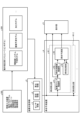
- FIG. 1 is a diagram showing a configuration example of a life prediction system realized by applying a life prediction device according to a first embodiment.
- the life prediction system shown in FIG. 1 includes a life prediction device 4, an electric motor system 100 whose life is to be predicted by the life prediction device 4, and a display unit 9 that displays the life prediction results of the life prediction device 4. include.
- the device status information 8 shown in FIG. 1 is used when the life prediction device 4 predicts the life of an object.
- the electric motor system 100 includes an electric motor control device 1, an electric motor 2, and a mechanism section 3, and is driven based on commands from a host controller (not shown).
- the motor control device 1 is mainly composed of a converter circuit 11, a smoothing capacitor 12 and an inverter circuit 13.
- the converter circuit 11 is composed of a plurality of rectifying elements and switching elements, and mainly converts the three-phase AC voltage of the input system power into a DC voltage by three-phase full-wave rectification. Output between bus line N.
- the smoothing capacitor 12 is arranged between the positive electrode bus line P and the negative electrode bus line N.
- the smoothing capacitor 12 removes the ripple component contained in the DC voltage rectified and output between the positive electrode bus P and the negative electrode bus N by the converter circuit 11 to generate a stable bus voltage.
- a first current sensor 51 is provided between the positive electrode bus line P and the smoothing capacitor 12 .
- a voltage sensor 52 is provided between the positive electrode bus line P and the negative electrode bus line N. As shown in FIG.
- the inverter circuit 13 is connected in parallel with the smoothing capacitor 12, and is composed of a plurality of rectifying elements and switching elements.
- the electric motor 2 is controlled by turning ON/OFF the switching element based on a drive command from an inverter control section (not shown).
- the electric motor 2 is connected to the inverter circuit 13 by a power cable.
- a power cable to the electric motor 2 is provided with a second current sensor 53 .
- the electric motor 2 is provided with an angle sensor 54 .
- the electric motor 2 is coupled with the mechanical section 3 via a coupling.
- the mechanism section 3 is composed of a ball screw 31, a nut 32, a table 33, a bearing 34 that supports the ball screw 31, and the like.
- a position sensor 55 for detecting the position of the table 33 is also provided.
- the sensor information 5 includes, for example, the bus current detected by the first current sensor 51, the bus voltage detected by the voltage sensor 52, the motor current detected by the second current sensor 53, and the angle sensor 54. machine speed and machine position detected by the position sensor 55; temperature measured by a temperature sensor (not shown); and humidity measured by a humidity sensor.
- the setting information 6 is information related to the operation of devices or parts preset in the electric motor system 100 .
- the setting information 6 includes the carrier frequency used when an inverter control unit (not shown) of the inverter circuit 13 generates a drive command, the cooling state of the devices that make up the electric motor system 100, and the cooling state of the devices that make up the electric motor system 100.
- the cooling state of the device is, for example, the operating state of a cooling fan provided in the electric motor 2 .
- the calculation information 7 is information calculated using part or all of the operating state of the mechanism section 3 and the sensor information 5, and includes the friction amount of the mechanism section 3 when the table 33 is moved, the load inertia, the operating time, processing conditions and the like.
- the device state information 8 which is information about the usage state of each device that configures the electric motor system 100. That is, the device state information 8 is composed of sensor information 5, setting information 6, and calculation information 7.
- FIG. 8 the device state information 8 is referred to in this specification, but the device state information 8 also includes information on the usage states of the components that make up the electric motor system 100 . Further, even when the object of life prediction is a part, the "part” may be described as the "apparatus”. For example, "device life” may mean the life of the device or the life of a part.
- the calculation information 7 is generated outside the life prediction device 4, but the calculation information 7 is generated inside the life prediction device 4 based on the sensor information 5. good too.
- the lifespan prediction device 4 includes one or more lifespan calculators 40-1, 40-2, .
- life calculation units 40 are provided in the same number as the devices and parts whose life is to be calculated. For example, if five of the devices and parts that make up the electric motor system 100 need life calculation, the life prediction device 4 includes five life calculation units 40-1 to 40-5. becomes.
- the life calculation unit 40 may be individually provided for each of the electric motor control device 1, the electric motor 2, and the mechanical unit 3 to predict the life of each of them, or may be provided in the parts constituting the electric motor system 100 It may be provided separately for each of the life-limited parts, such as the smoothing capacitor 12 of the motor control device 1 and the semiconductor element.
- the lifespan storage unit 44 stores in advance as lifespan data the basic lifespan, which is the initial lifespan at the start of operation of the device under the standard usage conditions, and the consumption lifespan, which is the lifespan consumed from the basic lifespan.
- the basic life is the life of the device (or part) when used under the conditions recommended by the manufacturer, for example, the life of the device when used under the recommended conditions described in the catalog of the device.
- the device stress inference unit 41 receives as input the device state information 8 generated based on the information obtained from the electric motor system 100 and infers the device stress from the input device state information 8 .
- Device stress deduction section 41 outputs the deduced device stress to life consumption amount deduction section 42 and display section 9 .
- the life consumption inference unit 42 receives the device stress as input and infers the life consumption from the input device stress.
- the life consumption inferring unit 42 outputs the inferred life consumption to the life prediction unit 43 .
- the lifespan consumption is the lifespan consumed per calculation cycle of the lifespan consumption inferring unit 42 .
- the consumption life contained in the above-mentioned life data is obtained by accumulating the life consumption from the start of operation of the device.
- ⁇ Ln is the life consumption amount
- ⁇ t is the calculation cycle of the life consumption amount inferring unit 42
- Ln is the consumption life.
- the life prediction unit 43 calculates the life of the object ( equipment or parts) life expectancy.
- the life prediction unit 43 outputs the predicted device life L predicted by calculation to the display unit 9 so as to notify the outside. Further, the life prediction unit 43 updates the consumption life Ln held by the life storage unit 44 based on the life consumption amount ⁇ Ln. That is, the life prediction unit 43 updates the life consumption Ln by adding the life consumption amount ⁇ Ln to the life consumption Ln held by the life storage unit 44 .
- the operation of the life calculation unit 40 corresponding to the smoothing capacitor 12 of the motor control device 1, that is, the operation of the life calculation unit 40 predicting the life of the smoothing capacitor 12 will be described.
- Ta is the ambient temperature of the smoothing capacitor 12 .
- ⁇ Tx is the temperature rise from ambient temperature.
- IR is the ripple current flowing through the smoothing capacitor 12 .
- ESR is the equivalent series resistance of the smoothing capacitor 12 .
- ⁇ is the heat dissipation coefficient of the smoothing capacitor 12 .
- the aluminum electrolytic capacitor used as the smoothing capacitor 12 causes deterioration in life according to the Arrhenius law due to thermal stress caused by the temperature rise.
- Lbc is the basic life of the smoothing capacitor 12 when the rated voltage is applied and the rated ripple voltage is applied under the operating upper limit temperature. To is the allowable internal temperature of the smoothing capacitor 12 .
- Vo is the rated voltage of the smoothing capacitor 12 .
- Vx is a DC voltage applied to the smoothing capacitor 12 during use.
- the exponent K is the applied voltage reduction rate of the smoothing capacitor 12 .
- the device stress inference unit 41 can be inferred by applying equation (2), the input device state information 8 is ambient temperature and bus current, and the output device stress is , the internal temperature Tx of the capacitor.
- the bus line current corresponds to the ripple current IR.
- the equivalent series resistance ESR and the heat radiation coefficient ⁇ are used as fixed values for calculation.
- the life consumption inference unit 42 can make inferences by applying formula (3).
- the life consumption inferring unit 42 uses the internal temperature Tx of the capacitor as the input device stress, and outputs the life time L obtained from the internal temperature Tx and equation (3) as the life consumption ⁇ Ln.
- the life prediction unit 43 calculates the predicted device life L from the life consumption ⁇ Ln using the above-described formula (1).
- the life prediction device 4 outputs the predicted device life L calculated by the life calculation unit 40 in this manner to the display unit 9 so as to notify the outside. Further, the life prediction device 4 outputs the obtained device state information 8 and the device stress inferred by the device stress inferring portion 41 to the display portion 9 so as to notify the outside.
- the display unit 9 displays the predicted device life L, device status information 8 and device stress output by the life prediction device 4 .
- the display unit 9 is provided in a device external to the life prediction device 4, such as a display device, but the display unit 9 may be provided inside the life prediction device 4. good.
- the life prediction device 4 only needs to be able to output the predicted device life L, the device state information 8 and the device stress so as to notify the outside of the life prediction device 4 .
- FIG. 2 is a diagram showing an example of the relationship between device stress and predicted device life.
- S min is the minimum device stress and S max is the maximum device stress.
- L min is the expected device life at minimum device stress and L max is the expected device life at maximum device stress.
- S x and L n denote device stress and predicted device life, respectively, at current operating conditions. In this way, the relationship between current operating conditions, device stress, and life can be easily grasped. Further, in the present embodiment, since the predicted device life is calculated from the life consumption amount, the predicted device life can be easily calculated when the device stress is changed.
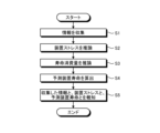
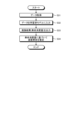
- FIG. 3 is a flow chart showing an example of the operation of the life prediction device 4 according to the first embodiment.
- the life prediction device 4 first collects information used for life prediction (step S1). That is, the life prediction device 4 acquires the above-described device state information 8 from the outside.
- the life prediction device 4 then infers device stress (step S2). That is, the device stress inference section 41 of the life calculation section 40 constituting the life prediction device 4 infers the device stress of the life prediction target based on the device state information 8 .
- the lifespan prediction device 4 then infers the lifespan consumption (step S3). That is, the life consumption inference unit 42 of the life calculation unit 40 constituting the life prediction device 4 infers the life consumption based on the device stress of the life prediction target.
- the life prediction device 4 next calculates the prediction device life (step S4). That is, the life prediction unit 43 of the life calculation unit 40 constituting the life prediction device 4 calculates the prediction device life based on the life consumption of the life prediction target.
- the life prediction device 4 then notifies the collected information, the device stress, and the predicted device life (step S5). That is, the life prediction device 4 outputs the information collected in step S1, the device stress inferred in step S2, and the predicted device life calculated in step S4 to the display unit 9, and causes the display unit 9 to display them. to notify the user.
- the life expectancy prediction device 4 can be realized by, for example, the hardware shown in FIG. FIG. 4 is a diagram showing an example of hardware that implements the life expectancy prediction device 4. As shown in FIG. 4
- processor 101 is a CPU (Central Processing Unit, central processing unit, processing unit, arithmetic unit, microprocessor, microcomputer, DSP (Digital Signal Processor)) or system LSI (Large Scale Integration).
- memory 102 include non-volatile or volatile semiconductor memories such as RAM (Random Access Memory), ROM (Read Only Memory), flash memory, magnetic disks, and the like.
- the processor 101 operates as a device stress inference section 41 , a life consumption amount inference section 42 and a life prediction section 43 by reading and executing this life prediction program from the memory 102 .
- life storage unit 44 that constitutes each life calculation unit 40 of the life prediction device 4 is implemented by the memory 102 .
- the processor 101 and the memory 102 shown in FIG. 4 may be hardware constituting a computer. That is, the life prediction device 4 may be realized by a computer having a processor 101 and a memory 102 and a life prediction program executed by the processor 101 of the computer. Each function of the life prediction device 4 may be implemented by a plurality of computers operating in cooperation.
- life prediction programs described above for operating as the device stress inference unit 41, the life consumption amount inference unit 42, and the life prediction unit 43 are pre-stored in the memory 102, the present invention is not limited to this.
- the life prediction program described above is written in a recording medium such as a CD (Compact Disc)-ROM or a DVD (Digital Versatile Disc)-ROM, and is supplied to the user. good. Further, the life expectancy prediction program described above may be provided to the user via a network such as the Internet.
- lifespan prediction device 4 Although the hardware that implements the lifespan prediction device 4 has been described, other lifespan prediction devices that will be described later can also be implemented with similar hardware.
- the life prediction apparatus 4 As described above, according to the life prediction apparatus 4 according to the present embodiment, a plurality of factors affecting the life according to the operating environment are simplified and calculated as one device stress, and the predicted device life is calculated. Since it is also possible to provide the information to the user, the user can easily grasp the operating environment of the machine and determine the maintenance conditions.
- FIG. 5 is a diagram showing another configuration example of the life prediction device according to the first embodiment.
- the life prediction device 4a includes life calculation units 40a-1, 40a-2, . . . instead of the life calculation units 40-1, 40-2, . .
- the life calculation unit 40a (life calculation units 40a-1, 40a-2, . 44a is replaced.
- the same reference numerals as in FIG. 1 denote the same constituent elements as in the life prediction device 4 shown in FIG.
- the description of the components denoted by the same reference numerals as in FIG. 1 is omitted.
- the life consumption inference unit 42a receives the deterioration coefficient calculated from the basic life and the consumption life from the life storage unit 44a.
- the deterioration coefficient may be calculated by the life storage unit 44a or by the life prediction unit 43.
- FIG. instead of inputting the deterioration coefficient to the life consumption amount inference unit 42a, information used for calculating the deterioration coefficient is input to the life consumption amount inference unit 42a, and the life consumption amount inference unit 42a calculates the deterioration coefficient. good too.
- the deterioration coefficient Lk input to the life consumption inferring unit 42a is the result of dividing the remaining life Lr, which is a value obtained by subtracting the consumption life from the basic life, by the basic life.
- the life consumption amount inferred by the life consumption amount inferring unit 42a can be corrected by using the coefficient Lk associated with deterioration as the amount of influence associated with deterioration of the prediction target. For example, as deterioration progresses in an aluminum electrolytic capacitor used as the smoothing capacitor 12, the capacitance decreases and the equivalent series resistance increases, so the error in the life estimation results increases as the deterioration progresses.
- the life prediction device 4a having the configuration shown in FIG. 5 is suitable, and the prediction accuracy can be improved.
- the lifespan consumption inferred by the lifespan consumption inference unit 42a is corrected, for example, by multiplying the lifespan consumption inferred in the same manner as the lifespan consumption inference unit 42 described above by the deterioration coefficient Lk.
- a deterioration coefficient may be included in the calculation formula used for inferring the lifetime consumption, and correction may be performed by updating the deterioration coefficient Lk each time the lifetime prediction unit 43 calculates the predicted device lifetime.
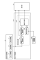
- FIG. 6 is a diagram showing a configuration example of a life prediction system realized by applying the life prediction device according to the second embodiment.
- a lifespan prediction system according to the second embodiment includes a lifespan prediction device 4, an information input device 300, and a motion estimation unit 200 similar to those in the first embodiment.
- Embodiment 1 the sensor information 5 and the calculated information 7 obtained by the electric motor system 100 actually operating were used as inputs to the life prediction device 4 together with the setting information 6 .
- motion estimating section 200 simulates the motion of electric motor system 100 under conditions input via information input device 300 and generates sensor information 5 and calculation information 7 .
- the information input device 300 is, for example, an electronic computer that executes software conforming to a CNC (Computerized Numerically Controlled) device that controls machine tools.
- Input information to the information input device 300 includes operating conditions (operating program or operating pattern, parameters, etc.), machine information (mechanical configuration, etc.), and operating environment (ambient temperature, power supply environment, etc.).
- the information input device 300 determines a movement command, simulation conditions (operating time, machine prediction model to be simulated), etc. based on the input information.
- the motion estimating unit 200 is a machine prediction model that includes the electric motor system prediction model selected by the information input device 300, performs a simulation according to the operating conditions input from the information input device 300, and outputs sensor information 5.
- the motion estimator 200 can be implemented, for example, by a computer and a program that causes the computer to execute a simulation.
- a lifespan prediction device 4 according to the present embodiment is the same as the lifespan prediction device 4 shown in FIG. 1 described in the first embodiment. Note that the life prediction device 4 shown in FIG. 6 may be replaced with the life prediction device 4a shown in FIG.
- FIG. 7 is a diagram showing an example of contents displayed on the display unit 9 by the life prediction device 4 according to the second embodiment. As shown in FIG. 7, the life prediction device 4 causes the display unit 9 to display the input conditions and the output results.
- the display unit 9 displays machine information, operating conditions, and operating environment as input conditions.
- the display unit 9 displays, as output results, device stress and predicted device life for each of the constituent devices and components (motor #1, motor #2, inverter unit, cooling fan, etc.) determined in the mechanical configuration. indicate.
- the device stress is defined as 100% when the basic life is achieved.
- the life prediction system As described above, according to the life prediction system according to the second embodiment, it is possible to grasp device stress and predicted device life under specified operating conditions without operating an industrial machine such as the electric motor system 100. It is possible to determine the operating conditions and mechanical configuration according to the life required by the user.
- FIG. 8 is a diagram showing a configuration example of the life prediction device 4b according to the third embodiment.
- the device status information 8 shown in FIG. 8 is similar to the device status information 8 described in the first embodiment, and is generated by the method described in the first or second embodiment.
- a lifespan prediction device 4b according to the third embodiment has a configuration in which a modified lifespan calculation unit 400 is added to the lifespan prediction device 4 according to the first embodiment.
- the life prediction device 4b shown in FIG. 8 is configured to include one set of the life calculation unit 40 and the modified life calculation unit 400, but may be configured to include two or more sets.
- the modified lifespan calculation unit 400 includes a lifespan comparison unit 401 , an operating condition changer 402 , a changed device stress inference unit 403 , a changed lifespan consumption amount inference unit 404 and a changed lifespan prediction unit 405 .
- the lifespan comparison unit 401 compares the predicted device lifespan calculated by the lifespan prediction unit 43 with the target device lifespan preset by the user. It is assumed that the target device life is stored in the life storage unit 44 . If the result of the comparison is "predicted device life ⁇ target device life", the operating condition changing unit 402 changes the operating condition.
- the operating condition changing unit 402 prestores operating conditions associated with the device status information 8 corresponding to the device whose life is to be predicted.
- the operating condition change unit 402 selects the electric motor that can be controlled by the motor control device 1 among the information included in the device state information 8. Targeting current, motor speed, machine speed, etc., the operating conditions are changed to reduce equipment stress.
- the operating conditions here include the time constant (acceleration) during acceleration/deceleration, operating speed, machining load, and the like.
- the changed device stress inferring unit 403, the changed life consumption amount inferring unit 404, and the changed life predicting unit 405 each Execute the process and calculate the change prediction device life.
- the change device stress inference unit 403 performs the same processing as the device stress inference unit 41 described above to infer the device stress.
- the modified lifespan consumption inference unit 404 performs the same processing as the lifespan consumption inference unit 42 described above to infer the lifespan consumption.
- the changed life prediction unit 405 performs the same processing as the life prediction unit 43 described above to obtain the predicted device life and outputs it as the changed predicted device life.
- the changed predicted device life is input to the life comparison unit 401 and compared with the target device life.
- the changed life calculation unit 400 calculates the operating conditions to be changed and the device status information 8 (changed The display unit 9 displays the post-apparatus status information 8) and the apparatus stress and predicted apparatus life obtained using the post-change apparatus status information 8).
- the operating condition changing unit 402 changes the operating conditions so as to further reduce the device stress.
- the changed device stress inferring unit 403, the changed life consumption amount inferring unit 404, and the changed life predicting unit 405 each execute processing to recalculate the changed predicted device life.
- the target device life stored in the life storage unit 44 is updated by subtracting the life consumption amount inferred by the life consumption amount inference unit 42 every calculation cycle of the life prediction unit 43 .
- FIG. 9 is a diagram showing an example of contents displayed on the display unit 9 by the life prediction device 4b according to the third embodiment. As shown in FIG. 9, the life prediction device 4b causes the display unit 9 to display the input conditions and the output results.
- the life prediction device 4b displays the input conditions, the output results, the details of the changes in the operating conditions, and the state of the device after the changes in the operating conditions (device stress, predicted device life) on the display unit 9.
- the "output result" shown in FIG. 9 is obtained by adding the target operating time to the "output result” shown in FIG.
- the "input condition” shown in FIG. 9 is obtained by adding an operating condition (target operating time) to the "input condition” shown in FIG.
- a plurality of operating conditions may be changed.
- FIG. 9 shows an example of changing two operating conditions, the time constant and the stop time.
- FIG. 9 shows an example in which the display unit 9 displays changes in operating conditions, device stress, and predicted device life, but the device stress is not essential. Displaying at least the change in operating conditions and the expected life of the device can provide the user with the necessary information.
- the life prediction device 4c may be configured to notify the control device 10 of the operating conditions to be changed and control to reduce device stress.
- FIG. 10 is a diagram showing another configuration example of the life prediction device according to the third embodiment.
- the life prediction device 4c shown in FIG. 10 When the life prediction device 4c shown in FIG. 10 is applied to realize a life prediction system, the actual operation of the life prediction object is automatically controlled so as to satisfy the target device life.
- the life prediction target is the electric motor system 100 described above
- the electric motor control device 1 is the control device 10 in FIG. 10 .
- the user can grasp the operating conditions for satisfying the target device life requested by the user. Further, according to the life prediction device 4c according to the third embodiment, it is possible to automatically change the operating conditions so as to satisfy the target device life.
- the lifespan calculation unit 40 of the lifespan prediction device 4b can be replaced with the lifespan calculation unit 40a of the lifespan prediction device 4a described in the first embodiment.
- the life calculation unit 40 of the life prediction device 4c can be replaced with the life calculation unit 40a.
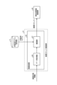
- FIG. 11 is a diagram showing a configuration example of a life prediction device 4d according to the fourth embodiment.
- the device status information 8 shown in FIG. 11 is similar to the device status information 8 described in the first embodiment, and is generated by the method described in the first or second embodiment.
- the basic configuration of a lifespan prediction device 4d according to the present embodiment is the same as that of the lifespan prediction device 4 according to the first embodiment. It is different from the life prediction device 4 in that it can be updated by consumption.
- the life consumption calculated by the life consumption inferring unit 42 of the life prediction device 4d is referred to as the first life consumption
- the life consumption calculated by the external life prediction device 450 is referred to as the second life consumption. Called lifetime consumption.
- the external lifetime prediction device 450 estimates the second lifetime consumption of the object by offline estimation.
- Offline estimation here is an estimation performed by a dedicated operation for estimating the consumption life during regular maintenance of the target object. In off-line estimation, it is possible to accurately calculate the life consumption by performing a dedicated operation for estimation, but there is a problem that the machine cannot be operated during that time.
- the external life prediction device 450 diagnoses life deterioration of the object, and sets the life deterioration amount obtained by the diagnosis as the second life consumption amount.
- the remaining life of the smoothing capacitor 12 can be calculated with high accuracy without calculating the amount of thermal stress. Mechanical motion must be stopped.
- online estimation here is real-time estimation that does not perform dedicated operations for estimation. Since online estimation does not require dedicated operations, lifetime consumption estimation can be performed while the machine continues to operate.
- the life prediction device 4d estimates the first life consumption amount by online estimation and updates the consumption life held by the life storage unit 44 by online estimation when the industrial machine is operating in a steady state, and the industrial machine During maintenance, the second life consumption is estimated by offline estimation and the life consumption held by the life storage unit 44 is updated, thereby obtaining a more accurate life estimation result during steady-state machine operation.
- the offline estimation is performed outside the life prediction device 4d, that is, the external life prediction device 450, the offline estimation may be performed inside the life prediction device 4d.
- a lifetime consumption estimator that performs offline estimation may be provided in the lifetime prediction device 4d.
- the life prediction device 4d According to the life prediction device 4d according to the fourth embodiment, it is possible to improve the accuracy of estimating the life of the prediction device.
- the device stress inference unit 41 of the life prediction device 4 according to the first embodiment described above can also be realized by applying machine learning. Therefore, in the present embodiment, a technique for realizing the device stress inference unit 41 by applying machine learning, specifically, a learning device that generates a trained model that realizes the device stress inference unit 41, and a learned model that realizes the device stress inference unit 41 An inference device that uses a model to infer device stress is described. As an example, a case where machine learning is applied to the device stress inference unit 41 of the life prediction device 4 will be described, but it is also possible to apply machine learning to the device stress inference unit 41 of the life prediction devices 4a to 4d described above. is.
- FIG. 12 is a diagram showing a configuration example of a learning device 61 that performs machine learning for realizing the device stress inference section 41 of the life prediction device 4.
- the learning device 61 includes a data acquisition section 62 and a model generation section 63 .
- the learning device 61 may be provided inside the lifespan prediction device 4 or may be provided outside the lifespan prediction device 4 .
- the learned model storage unit 71 shown in FIG. 12 may be provided outside the learning device 61 or may be provided inside the learning device 61 .
- the data acquisition unit 62 obtains data such as ambient temperature, bus voltage, bus current, motor current, carrier frequency, motor applied voltage, cooling state of the apparatus, motor rotation speed, friction amount, transported material amount, load inertia, feed speed, and machine position. , humidity, operating time, and processing conditions, and apparatus stress as learning data.
- Device stress corresponds to training data for machine learning.
- the device stress acquired by the data acquisition unit 62 differs depending on the trained model to be generated.
- the device stress is the capacitor temperature.
- the junction temperature is used as the device stress.
- the device stress is the coil temperature of the electric motor 2.
- the electric motor 2 it is well known that the deterioration of the insulating material of the coil progresses according to the temperature.
- the device stress is taken as the axial load. It is well known that an axial load affects the service life of the component parts (ball screw 31, bearing 34, etc.) of the mechanism section 3 .
- the model generation unit 63 learns the relationship between the device state information 8 and the device stress based on the learning data created based on the combination of the device state information 8 and the device stress output from the data acquisition unit 62 . That is, the model generation unit 63 generates a learned model that outputs the optimum device stress when the device state information 8 of the life prediction target is input.
- the learning data is data in which the device state information 8 and the device stress are associated with each other.
- the learning device 61 is used to learn the device stress corresponding to the device state information 8.
- the learning device 61 is connected to the life prediction device 4 via a network, and is a separate device from the life prediction device 4. It may be configured to operate as Also, the learning device 61 may be incorporated in the life prediction device 4 . Furthermore, the learning device 61 may reside on a cloud server.
- the learning algorithm used by the model generation unit 63 can be a known algorithm such as supervised learning, unsupervised learning, or reinforcement learning. As an example, a case where a neural network is applied will be described.
- the model generation unit 63 learns the device stress corresponding to the device state information 8 by so-called supervised learning according to the neural network model.
- supervised learning refers to a method in which input and result (label) data sets are given to the learning device 61 to learn the features of the learning data, and the result is inferred from the input.
- a neural network consists of an input layer consisting of multiple neurons, an intermediate layer (hidden layer) consisting of multiple neurons, and an output layer consisting of multiple neurons.
- the intermediate layer may be one layer, or two or more layers.
- FIG. 13 is a diagram for explaining the neural network.
- a three-layer neural network as shown in FIG. Y (Y1-Y2) is input, and the result is further multiplied by weight W2 (w21-w26) and output from output layer Z (Z1-Z3).
- W2 weight of weight W1
- W2 weight of weight W2
- Z1-Z3 output layer Z
- the neural network used in the model generation unit 63 of the learning device 61 performs a so-called The device stress corresponding to the device state information 8 is learned by supervised learning.
- the neural network learns by adjusting the weights W1 and W2 so that the device state information 8 is input to the input layer and the result output from the output layer approaches the device stress.
- the model generation unit 63 generates and outputs a learned model by executing the above learning.
- the learned model storage unit 71 stores the learned model output from the model generation unit 63.
- FIG. 14 is a flow chart showing an example of the operation of the learning device 61. As shown in FIG. 14
- the learning device 61 first acquires learning data (step S11). Specifically, the data acquisition unit 62 acquires the device state information 8 and the device stress, associates them, and creates learning data. Although the device status information 8 and the device stress are acquired at the same time, it is sufficient to acquire the device status information 8 and the device stress in association with each other. may
- the learning device 61 then performs learning processing (step S12). Specifically, the model generation unit 63 generates the device state information 8 by so-called supervised learning according to the learning data created based on the combination of the device state information 8 acquired by the data acquisition unit 62 and the device stress. and generate a trained model.
- the learning device 61 next stores the learned model in the learned model storage unit 71 (step S13). Specifically, the model generation unit 63 outputs the learned model generated in step S12, and the learned model storage unit 71 stores the learned model.
- FIG. 15 is a diagram showing a configuration example of an inference device 65 that implements the device stress inference unit 41 of the life prediction device 4.
- the inference device 65 includes a data acquisition unit 66 and an inference unit 67 .
- the inference device 65 may be provided inside the lifespan prediction device 4 or may be provided outside the lifespan prediction device 4 .
- a trained model storage unit 71 shown in FIG. 15 corresponds to the trained model storage unit 71 shown in FIG. 12 and stores a trained model generated by the learning device 61 .
- the data acquisition unit 66 acquires the device status information 8.
- the inference unit 67 uses the learned model stored in the learned model storage unit 71 to infer the device stress corresponding to the device state information 8 . That is, the inference unit 67 inputs the device state information 8 acquired by the data acquisition unit 66 to the learned model stored in the learned model storage unit 71, executes inference, and acquires device stress as an inference result. .
- the inference device 65 is used to infer the device stress corresponding to the device state information 8.
- the inference device 65 is connected to the life prediction device 4 via a network, and is a separate device from the life prediction device 4. It may be configured to operate as Also, the inference device 65 may be incorporated in the life prediction device 4 .
- the reasoning device 65 may reside on a cloud server.
- the inference device 65 infers device stress using the learned model generated by the learning device 61 that constitutes the life prediction device 4.
- the inference device 65 A trained model generated outside the prediction device 4 may be acquired and device stress may be inferred using this trained model.
- FIG. 16 is a flowchart showing an example of the operation of the life prediction device according to the fifth embodiment for estimating the life of an object using the inference device 65.
- FIG. 16 is a flowchart showing an example of the operation of the life prediction device according to the fifth embodiment for estimating the life of an object using the inference device 65.
- the inference device 65 first acquires data used for inference of device stress (step S21). Specifically, the data acquisition unit 66 acquires the device status information 8 .
- the inference device 65 then inputs the data acquired in step S21 to the learned model stored in the learned model storage unit 71 (step S22) to obtain an inference result. That is, the inference unit 67 inputs the device state information 8 acquired by the data acquisition unit 66 to the learned model stored in the learned model storage unit 71, and the device stress output from the learned model along with this. to get
- the inference device 65 then outputs device stress as the inference result (step S23), and based on this device stress, the life consumption amount inference unit 42 and the life prediction unit 43 estimate the device life (step S24). .
- the estimated device life is output from the life prediction section 43 to the display section 9 as a predicted device life.
- the device state information 8 including information that can be obtained from the electric motor system 100, factors that change in the operating environment can be inferred as device stress, making it possible to easily and highly accurately predict the service life.
- supervised learning is applied to the learning algorithm used by the model generation unit 63
- the present invention is not limited to this.
- reinforcement learning unsupervised learning, semi-supervised learning, and the like as learning algorithms.
- the model generation unit 63 may learn device stress according to learning data created for a plurality of industrial machines.
- the model generation unit 63 may acquire learning data from a plurality of industrial machines used in the same area, or may acquire learning data collected from a plurality of industrial machines operating independently in different areas. It is also possible to learn the device stress using the data for the device. It is also possible to add or remove industrial machines that collect data for learning from the targets on the way.
- a learning device that has learned the device stress for a certain industrial machine may be applied to another industrial machine to re-learn and update the device stress for the other industrial machine.
- model generation unit 63 deep learning that learns to extract the feature amount itself can be used, and other known methods such as genetic programming, functional logic programming, Machine learning may be performed according to support vector machines and the like.
- Embodiment 6 In the fifth embodiment, a case has been described in which machine learning is applied to realize the device stress inferring unit 41 of the life prediction device 4, but it is also possible to apply machine learning to realize the life consumption amount inferring unit 42. be. Therefore, in the present embodiment, a technique for realizing the life consumption inference unit 42 by applying machine learning, specifically, a learning device that generates a trained model that realizes the life consumption inference unit 42, and An inference device that infers lifetime consumption using a trained model will be described. As an example, a case where machine learning is applied to the life consumption amount inferring unit 42 of the life prediction device 4 will be described, but it is also possible to apply machine learning to the life consumption amount inference unit 42a of the life prediction device 4a described above. In addition, it is also possible to apply machine learning to the lifetime consumption inferring unit 42 of the lifetime prediction devices 4b to 4d.
- a learning phase in which the learning device generates a learned model that realizes the life consumption amount inference unit 42, and the life consumption amount inference unit 42 is realized by the inference device inferring the life consumption amount using the learned model.
- the explanation will be divided into the utilization phase and the utilization phase.
- FIG. 17 is a diagram showing a configuration example of a learning device 81 that performs machine learning for realizing the life consumption inference unit 42 of the life prediction device 4.
- the learning device 81 includes a data acquisition section 82 and a model generation section 83 .
- the learning device 81 may be provided inside the lifespan prediction device 4 or may be provided outside the lifespan prediction device 4 .
- the learned model storage unit 72 shown in FIG. 17 may be provided outside the learning device 81 or may be provided inside the learning device 81 .
- the data acquisition unit 82 acquires device stress and life consumption as learning data. Lifetime consumption corresponds to training data for machine learning. The life consumption amount is calculated based on, for example, the time until the device breaks down when operated with a constant device stress, that is, based on the actual life data and the calculation cycle ⁇ t of the life consumption amount inferring unit 42 . The data acquisition unit 82 may also acquire the above-described deterioration coefficient as learning data in addition to the device stress.
- the model generation unit 83 learns the relationship between the device stress and the life consumption based on the learning data created based on the combination of the device stress and the life consumption output from the data acquisition unit 82 . That is, the model generation unit 83 generates a learned model that outputs the optimum life consumption when the device stress of the life prediction target is input.
- the learning data is data in which the device stress and the life consumption are associated with each other.
- the learning device 81 is used to learn the life consumption corresponding to the device stress. It may be a configuration that operates. Also, the learning device 81 may be incorporated in the life prediction device 4 . Furthermore, the learning device 81 may reside on a cloud server.
- the learning algorithm used by the model generating unit 83 can be a known algorithm such as supervised learning, unsupervised learning, or reinforcement learning, like the model generating unit 63 of the learning device 61 described above.
- the operation of the model generation unit 83 to generate a trained model is the same as the operation of the model generation unit 63 of the learning device 61 described above to generate a trained model, except that the learning data used is different. Therefore, the detailed description of the operation of the model generation unit 83 to generate a trained model is omitted.
- the model generation unit 83 outputs the generated learned model to the learned model storage unit 72 .
- the learned model storage unit 72 stores the learned model output from the model generation unit 83.
- FIG. 18 is a diagram showing a configuration example of an inference device 85 that implements the life consumption inference unit 42 of the life prediction device 4.
- the inference device 85 includes a data acquisition unit 86 and an inference unit 87 .
- the inference device 85 may be provided inside the lifespan prediction device 4 or may be provided outside the lifespan prediction device 4 .
- a trained model storage unit 72 shown in FIG. 18 corresponds to the trained model storage unit 72 shown in FIG. 17 and stores a trained model generated by the learning device 81 .
- the data acquisition unit 86 acquires device stress.
- the inference unit 87 uses the learned model stored in the learned model storage unit 72 to infer the lifetime consumption corresponding to the device stress. That is, the inference unit 87 inputs the apparatus stress acquired by the data acquisition unit 86 to the learned model stored in the learned model storage unit 72 to execute inference, and acquires the life consumption as an inference result.
- the inference device 85 is used to infer the life consumption corresponding to the device stress. It may be a configuration that operates. Also, the inference device 85 may be incorporated in the life prediction device 4 . Furthermore, the inference device 85 may reside on a cloud server.
- the inference device 85 infers the life consumption using the learned model generated by the learning device 81 that constitutes the life prediction device 4, but the inference device 85 A trained model generated outside the life expectancy prediction device 4 may be acquired, and the life consumption amount may be inferred using this learned model.
- FIG. 19 is a flowchart showing an example of the operation of the life prediction device according to the sixth embodiment for estimating the life of an object using the inference device 85. As shown in FIG. 19
- the inference device 85 first acquires data used for inference of life consumption (step S31). Specifically, the data acquisition unit 86 acquires device stress.
- the inference device 85 then inputs the data acquired in step S31 to the learned model stored in the learned model storage unit 72 (step S32) to obtain an inference result. That is, the inference unit 87 inputs the device stress acquired by the data acquisition unit 86 to the learned model stored in the learned model storage unit 72, and accordingly, the lifetime consumption output from the learned model is calculated as get.
- the inference device 85 then outputs the life consumption amount as the inference result (step S33), and the life prediction unit 43 estimates the device life based on this life consumption amount (step S34).
- the estimated device life is output from the life prediction section 43 to the display section 9 as a predicted device life.
- the learning device 81 includes the above-described deterioration coefficient in the learning data used in machine learning, and the model generation unit 83 performs learning for inferring the life consumption from the device stress and the deterioration coefficient. may be generated.
- the inference device 85 acquires the deterioration factor in addition to the device stress, and infers the lifetime consumption from the acquired device stress and the deterioration factor.
Landscapes
- Engineering & Computer Science (AREA)
- Power Engineering (AREA)
- Artificial Intelligence (AREA)
- Evolutionary Computation (AREA)
- Databases & Information Systems (AREA)
- Testing And Monitoring For Control Systems (AREA)
- Control Of Electric Motors In General (AREA)
Abstract
Description
図1は、実施の形態1にかかる寿命予測装置を適用して実現される寿命予測システムの構成例を示す図である。図1に示す寿命予測システムは、寿命予測装置4と、寿命予測装置4が寿命を予測する対象の電動機システム100と、寿命予測装置4による寿命の予測結果などを表示する表示部9と、を含む。図1に示す装置状態情報8は、寿命予測装置4が対象物の寿命を予測する際に用いられる。
L = Lr/ΔLn×Δt …(1)
Tx = Ta+ΔTx = Ta+IR^2×ESR×β …(2)
L = Lbc×[2^{(To-Tx)/10}]×(Vo/Vx)^K …(3)
図6は、実施の形態2にかかる寿命予測装置を適用して実現される寿命予測システムの構成例を示す図である。実施の形態2にかかる寿命予測システムは、実施の形態1と同様の寿命予測装置4と、情報入力装置300と、動作推定部200とを含む。
図8は、実施の形態3にかかる寿命予測装置4bの構成例を示す図である。なお、図8に示す装置状態情報8は、実施の形態1で説明した装置状態情報8と同様のものであり、実施の形態1または実施の形態2で示した方法により生成される。
図11は、実施の形態4にかかる寿命予測装置4dの構成例を示す図である。なお、図11に示す装置状態情報8は、実施の形態1で説明した装置状態情報8と同様のものであり、実施の形態1または実施の形態2で示した方法により生成される。
上述した実施の形態1にかかる寿命予測装置4の装置ストレス推論部41は、機械学習を適用して実現することも可能である。そこで、本実施の形態では、機械学習を適用して装置ストレス推論部41を実現する手法、具体的には、装置ストレス推論部41を実現する学習済モデルを生成する学習装置、および、学習済モデルを利用して装置ストレスを推論する推論装置について、説明する。なお、一例として、寿命予測装置4の装置ストレス推論部41に機械学習を適用する場合について説明するが、上述した寿命予測装置4a~4dの装置ストレス推論部41に機械学習を適用することも可能である。
図12は、寿命予測装置4の装置ストレス推論部41を実現するための機械学習を行う学習装置61の構成例を示す図である。学習装置61は、データ取得部62およびモデル生成部63を備える。学習装置61は、寿命予測装置4の内部に設けられてもよいし、寿命予測装置4の外部に設けられてもよい。また、図12に示す学習済モデル記憶部71は、学習装置61の外部に設けられていてもよいし、学習装置61の内部に設けられていてもよい。
つづいて、推論装置が学習済モデルを用いて装置ストレスを推論する活用フェーズについて説明する。
実施の形態5では、機械学習を適用して寿命予測装置4の装置ストレス推論部41を実現する場合について説明したが、機械学習を適用して寿命消費量推論部42を実現することも可能である。そこで、本実施の形態では、機械学習を適用して寿命消費量推論部42を実現する手法、具体的には、寿命消費量推論部42を実現する学習済モデルを生成する学習装置、および、学習済モデルを利用して寿命消費量を推論する推論装置について、説明する。なお、一例として、寿命予測装置4の寿命消費量推論部42に機械学習を適用する場合について説明するが、上述した寿命予測装置4aの寿命消費量推論部42aに機械学習を適用することも可能であるし、寿命予測装置4b~4dの寿命消費量推論部42に機械学習を適用することも可能である。
図17は、寿命予測装置4の寿命消費量推論部42を実現するための機械学習を行う学習装置81の構成例を示す図である。学習装置81は、データ取得部82およびモデル生成部83を備える。学習装置81は、寿命予測装置4の内部に設けられてもよいし、寿命予測装置4の外部に設けられてもよい。また、図17に示す学習済モデル記憶部72は、学習装置81の外部に設けられていてもよいし、学習装置81の内部に設けられていてもよい。
つづいて、推論装置が学習済モデルを用いて装置ストレスを推論する活用フェーズについて説明する。
Claims (24)
- 産業用機械を構成する装置または部品である対象物の基本寿命および当該基本寿命から消費した寿命である消費寿命を寿命データとして保持する寿命記憶部と、
前記対象物の使用状態に関する情報である装置状態情報に基づいて装置ストレスを推論する装置ストレス推論部と、
前記装置ストレスに基づいて、定められた周期あたりに消費した前記対象物の寿命である寿命消費量を推論する寿命消費量推論部と、
前記寿命記憶部が保持する前記寿命データおよび前記寿命消費量に基づいて前記対象物の予測装置寿命を予測する寿命予測部と、
を備え、
装置ストレス推論部で推論された前記装置ストレス、及び前記寿命予測部で予測された前記予測装置寿命を外部に通知するように出力する、
ことを特徴とする寿命予測装置。 - 前記寿命予測部は、前記寿命消費量が前記寿命消費量推論部から入力されるごとに、前記対象物の前記予測装置寿命を予測するとともに、入力された前記寿命消費量に基づいて、前記寿命記憶部が保持する寿命データに含まれる消費寿命を更新する、
ことを特徴とする請求項1に記載の寿命予測装置。 - 前記装置状態情報は、前記対象物に設けられたセンサが検出するセンサ情報と、前記対象物の動作に関する情報と、を含む、
ことを特徴とする請求項1または2に記載の寿命予測装置。 - 前記寿命消費量推論部は、前記寿命消費量を推論後、前記基本寿命および前記消費寿命に基づいて算出された劣化係数を用いて前記寿命消費量の推論結果を補正し、補正後の推論結果を出力する、
ことを特徴とする請求項1から3のいずれか一つに記載の寿命予測装置。 - 前記基本寿命から前記消費寿命を減算して得られる値を前記基本寿命で除した結果を前記劣化係数とする、
ことを特徴とする請求項4に記載の寿命予測装置。 - 前記装置状態情報が、指定した動作条件に従って前記対象物の動作のシミュレーションを実施する動作推定部が出力する情報に基づいて生成される、
ことを特徴とする請求項1から5のいずれか一つに記載の寿命予測装置。 - 前記装置状態情報を外部に通知するように出力する、
ことを特徴とする請求項1から6のいずれか一つに記載の寿命予測装置。 - 前記寿命予測部による寿命の予測結果である前記予測装置寿命が予め定められた目標装置寿命よりも短い場合に、前記装置ストレス推論部が推論する前記装置ストレスが減少するよう前記装置状態情報を変更する動作条件変更部、
を備えることを特徴とする請求項1から7のいずれか一つに記載の寿命予測装置。 - 前記動作条件変更部が前記装置状態情報を変更した場合、
前記動作条件変更部による前記装置状態情報の変更内容と、変更後の前記装置状態情報に対応する条件で前記対象物が動作した場合の前記対象物の変更予測装置寿命の予測結果と、を外部に通知するように出力する、
ことを特徴とする請求項8に記載の寿命予測装置。 - 前記動作条件変更部が前記装置状態情報を変更した場合、変更後の前記装置状態情報を前記対象物に出力し、変更後の前記装置状態情報が示す条件で前記対象物を動作させる、
ことを特徴とする請求項8に記載の寿命予測装置。 - 前記対象物の前記寿命消費量をオフライン推定により求める寿命消費量推定部、
を備え、
前記対象物が稼働中は前記寿命消費量推論部が求めた寿命消費量を使用して前記寿命予測部が前記予測装置寿命を予測し、
前記対象物が停止中は前記寿命消費量推定部が求めた寿命消費量を使用して前記寿命予測部が前記予測装置寿命を予測する、
ことを特徴とする請求項1から10のいずれか一つに記載の寿命予測装置。 - 前記装置状態情報は、電動機制御装置の周囲温度、前記電動機制御装置の電源電圧、前記電動機制御装置の電源周波数、前記電動機制御装置の母線電圧、前記電動機制御装置の母線電流、前記電動機制御装置が制御する電動機の電動機電流、前記電動機制御装置が電動機の制御に用いるキャリア周波数、前記電動機制御装置の冷却状態、前記電動機制御装置が制御する電動機の回転数、前記電動機制御装置が制御する電動機に接続された機械の移動速度、前記電動機制御装置が制御する電動機に接続された機械の摩擦量、前記電動機制御装置が制御する電動機に接続された機械の負荷イナーシャ、前記電動機制御装置が制御する電動機に接続された機械の軸方向荷重、前記電動機制御装置が制御する電動機に接続された機械の振動、前記電動機制御装置の設置場所の標高、前記電動機制御装置の設置場所の湿度、前記電動機制御装置の稼働時間、および、前記電動機制御装置を用いて行う加工の加工条件、のうちの少なくとも一つを含む、
ことを特徴とする請求項1から11のいずれか一つに記載の寿命予測装置。 - 前記装置ストレスを電動機制御装置に接続されるまたは内蔵されるコンデンサの温度とする、
ことを特徴とする請求項1から12のいずれか一つに記載の寿命予測装置。 - 前記装置ストレスを電動機制御装置に内蔵されるスイッチング素子の温度とする、
ことを特徴とする請求項1から12のいずれか一つに記載の寿命予測装置。 - 前記装置ストレスを電動機制御装置に制御される電動機のコイルの温度とする、
ことを特徴とする請求項1から12のいずれか一つに記載の寿命予測装置。 - 前記装置ストレスを電動機制御装置に制御される電動機に接続された機械の軸方向荷重とする、
ことを特徴とする請求項1から12のいずれか一つに記載の寿命予測装置。 - 請求項1から16のいずれか一つに記載の寿命予測装置と、
前記対象物を含む電動機システムと、
を備えることを特徴とする寿命予測システム。 - 産業用機械を構成する装置または部品である対象物の使用状態に関する情報である装置状態情報と、前記対象物の寿命予測に用いる装置ストレスとを取得するデータ取得部と、
前記装置状態情報および前記装置ストレスに基づいて作成される学習用データを用いて、前記装置状態情報から前記装置ストレスを推論するための学習済モデルを生成するモデル生成部と、
を備えることを特徴とする学習装置。 - 産業用機械を構成する装置または部品である対象物の使用状態に関する情報である装置状態情報を取得するデータ取得部と、
前記装置状態情報から前記対象物の寿命予測に用いる装置ストレスを推論するための学習済モデルを用いて、前記データ取得部が取得した前記装置状態情報から前記装置ストレスを推論する推論部と、
を備えることを特徴とする推論装置。 - 産業用機械を構成する装置または部品である対象物の寿命予測に用いる装置ストレスと、定められた周期あたりに消費した前記対象物の寿命である寿命消費量とを取得するデータ取得部と、
前記装置ストレスおよび前記寿命消費量に基づいて作成される学習用データを用いて、前記装置ストレスから前記寿命消費量を推論するための学習済モデルを生成するモデル生成部と、
を備えることを特徴とする学習装置。 - 前記データ取得部は、前記装置ストレスおよび前記寿命消費量に加えて、前記対象物の基本寿命および当該基本寿命から消費した寿命である消費寿命に基づいて算出された劣化係数を取得し、
前記モデル生成部は、前記装置ストレスおよび前記劣化係数から前記寿命消費量を推論するための学習済モデルを生成する、
ことを特徴とする請求項20に記載の学習装置。 - 産業用機械を構成する装置または部品である対象物の装置ストレスを取得するデータ取得部と、
前記装置ストレスから定められた周期あたりに消費した前記対象物の寿命である寿命消費量を推論するための学習済モデルを用いて、前記データ取得部が取得した前記装置ストレスから前記寿命消費量を推論する推論部と、
を備えることを特徴とする推論装置。 - 前記データ取得部は、前記装置ストレスに加えて、前記対象物の基本寿命および当該基本寿命から消費した寿命である消費寿命に基づいて算出された劣化係数を取得し、
前記推論部は、
前記装置ストレスおよび前記劣化係数から前記寿命消費量を推論するための前記学習済モデルを用いて、前記データ取得部が取得した前記装置ストレスおよび前記劣化係数から前記寿命消費量を推論する、
ことを特徴とする請求項22に記載の推論装置。 - 産業用機械を構成する装置または部品である対象物の基本寿命および当該基本寿命から消費した寿命である消費寿命を寿命データとして保持する第1ステップと、
前記対象物の使用状態に関する情報である装置状態情報に基づいて装置ストレスを推論する第2ステップと、
前記装置ストレスに基づいて、定められた周期あたりに消費した前記対象物の寿命である寿命消費量を推論する第3ステップと、
前記第1ステップで保持した前記寿命データおよび前記寿命消費量に基づいて前記対象物の寿命を予測する第4ステップと、
をコンピュータに実行させることを特徴とする寿命予測プログラム。
Priority Applications (4)
| Application Number | Priority Date | Filing Date | Title |
|---|---|---|---|
| CN202180098747.3A CN117441291B (zh) | 2021-12-01 | 2021-12-01 | 寿命预测装置、寿命预测系统、学习装置、推断装置及计算机程序产品 |
| JP2022522394A JP7090832B1 (ja) | 2021-12-01 | 2021-12-01 | 寿命予測装置、寿命予測システム、学習装置、推論装置および寿命予測プログラム |
| DE112021007632.9T DE112021007632T5 (de) | 2021-12-01 | 2021-12-01 | Lebensdauervorhersagevorrichtung, Lebensdauervorhersagesystem, Lernvorrichtung, Inferenzvorrichtung und Lebensdauervorhersageprogramm |
| PCT/JP2021/044155 WO2023100300A1 (ja) | 2021-12-01 | 2021-12-01 | 寿命予測装置、寿命予測システム、学習装置、推論装置および寿命予測プログラム |
Applications Claiming Priority (1)
| Application Number | Priority Date | Filing Date | Title |
|---|---|---|---|
| PCT/JP2021/044155 WO2023100300A1 (ja) | 2021-12-01 | 2021-12-01 | 寿命予測装置、寿命予測システム、学習装置、推論装置および寿命予測プログラム |
Publications (1)
| Publication Number | Publication Date |
|---|---|
| WO2023100300A1 true WO2023100300A1 (ja) | 2023-06-08 |
Family
ID=82155954
Family Applications (1)
| Application Number | Title | Priority Date | Filing Date |
|---|---|---|---|
| PCT/JP2021/044155 Ceased WO2023100300A1 (ja) | 2021-12-01 | 2021-12-01 | 寿命予測装置、寿命予測システム、学習装置、推論装置および寿命予測プログラム |
Country Status (4)
| Country | Link |
|---|---|
| JP (1) | JP7090832B1 (ja) |
| CN (1) | CN117441291B (ja) |
| DE (1) | DE112021007632T5 (ja) |
| WO (1) | WO2023100300A1 (ja) |
Families Citing this family (6)
| Publication number | Priority date | Publication date | Assignee | Title |
|---|---|---|---|---|
| JP7757890B2 (ja) * | 2022-07-12 | 2025-10-22 | 株式会社デンソー | モータ駆動装置、および車載システム |
| KR102826212B1 (ko) * | 2022-09-13 | 2025-06-27 | 주식회사 레오이노비젼 | 분류 및 다중 회귀 하이브리드 기계학습 알고리즘을 활용한 부품 단종시점 예측 방법 |
| WO2024127670A1 (ja) * | 2022-12-16 | 2024-06-20 | 三菱電機株式会社 | 推論装置および推論方法 |
| WO2024127671A1 (ja) * | 2022-12-16 | 2024-06-20 | 三菱電機株式会社 | 推論装置および推論方法 |
| WO2024127672A1 (ja) * | 2022-12-16 | 2024-06-20 | 三菱電機株式会社 | 推論装置および推論方法 |
| WO2025154141A1 (ja) * | 2024-01-15 | 2025-07-24 | 三菱電機株式会社 | 制御装置、電気機器、制御方法、制御プログラム、および制御システム |
Citations (4)
| Publication number | Priority date | Publication date | Assignee | Title |
|---|---|---|---|---|
| JP2003090868A (ja) * | 2001-09-19 | 2003-03-28 | Konica Corp | 寿命推定装置及び寿命推定方法 |
| JP2017046540A (ja) * | 2015-08-28 | 2017-03-02 | ファナック株式会社 | 電動機の予測寿命を学習する機械学習装置および方法ならびに該機械学習装置を備えた寿命予測装置および電動機システム |
| JP2020034473A (ja) * | 2018-08-31 | 2020-03-05 | ファナック株式会社 | ファンモータの寿命予測方法およびファンモータの寿命予測装置 |
| JP2020038313A (ja) * | 2018-09-05 | 2020-03-12 | コニカミノルタ株式会社 | 画像形成装置 |
Family Cites Families (4)
| Publication number | Priority date | Publication date | Assignee | Title |
|---|---|---|---|---|
| JP3721853B2 (ja) * | 1999-05-26 | 2005-11-30 | 日産自動車株式会社 | 組電池の寿命及び残容量判定装置 |
| DE102015001050A1 (de) * | 2015-01-29 | 2016-08-04 | Man Truck & Bus Ag | Verfahren und Vorrichtung zur Steuerung und/oder Regelung mindestens eines einen Alterungszustand eines elektrischen Energiespeichers beeinflussenden Betriebsparameters des elektrischen Energiespeichers |
| JP7014121B2 (ja) | 2018-10-03 | 2022-02-01 | オムロン株式会社 | 電源システム、電源装置の動作状態表示法、およびプログラム |
| KR102092185B1 (ko) * | 2019-10-07 | 2020-05-26 | 팩트얼라이언스 주식회사 | 중전기기 건전성 분석 플랫폼 및 이를 이용하는 분석 방법 |
-
2021
- 2021-12-01 DE DE112021007632.9T patent/DE112021007632T5/de active Pending
- 2021-12-01 JP JP2022522394A patent/JP7090832B1/ja active Active
- 2021-12-01 CN CN202180098747.3A patent/CN117441291B/zh active Active
- 2021-12-01 WO PCT/JP2021/044155 patent/WO2023100300A1/ja not_active Ceased
Patent Citations (4)
| Publication number | Priority date | Publication date | Assignee | Title |
|---|---|---|---|---|
| JP2003090868A (ja) * | 2001-09-19 | 2003-03-28 | Konica Corp | 寿命推定装置及び寿命推定方法 |
| JP2017046540A (ja) * | 2015-08-28 | 2017-03-02 | ファナック株式会社 | 電動機の予測寿命を学習する機械学習装置および方法ならびに該機械学習装置を備えた寿命予測装置および電動機システム |
| JP2020034473A (ja) * | 2018-08-31 | 2020-03-05 | ファナック株式会社 | ファンモータの寿命予測方法およびファンモータの寿命予測装置 |
| JP2020038313A (ja) * | 2018-09-05 | 2020-03-12 | コニカミノルタ株式会社 | 画像形成装置 |
Also Published As
| Publication number | Publication date |
|---|---|
| JP7090832B1 (ja) | 2022-06-24 |
| CN117441291B (zh) | 2024-10-01 |
| DE112021007632T5 (de) | 2024-02-29 |
| JPWO2023100300A1 (ja) | 2023-06-08 |
| CN117441291A (zh) | 2024-01-23 |
Similar Documents
| Publication | Publication Date | Title |
|---|---|---|
| JP7090832B1 (ja) | 寿命予測装置、寿命予測システム、学習装置、推論装置および寿命予測プログラム | |
| CN106485343B (zh) | 机械学习装置及方法、寿命预测装置及电动机系统 | |
| JP6243385B2 (ja) | モータ電流制御における補正値を学習する機械学習装置および方法ならびに該機械学習装置を備えた補正値計算装置およびモータ駆動装置 | |
| CN107491038B (zh) | 学习异常负载检测的阈值的机械学习机、数控装置以及机械学习方法 | |
| JP6010204B1 (ja) | パワー素子の予測寿命を学習する機械学習装置及び方法並びに該機械学習装置を備えた寿命予測装置及びモータ駆動装置 | |
| JPWO2023100300A5 (ja) | ||
| JP5375948B2 (ja) | 冷却装置を有する電子装置および冷却プログラム | |
| CN114256832A (zh) | 配电网电压的区域协调控制方法、装置与电子设备 | |
| JP2019528032A (ja) | バッテリ管理システム | |
| KR101515743B1 (ko) | 설비기기의 디맨드 제어 장치 | |
| US20230229220A1 (en) | Systems and Methods for Predicting Power Converter Health | |
| JP5241765B2 (ja) | 電力管理システム及びプログラム | |
| CN113544959B (zh) | 具有人工智能的中压变频驱动器 | |
| JP7577476B2 (ja) | ロボットシステムおよび回生抵抗の寿命予測方法 | |
| AU2022204337B2 (en) | Run-time reliability reporting for electrical hardware systems | |
| WO2018122635A1 (en) | Method and system for regulating temperature of data center | |
| CN113530762A (zh) | 状态监视装置以及状态监视方法 | |
| CN118301911A (zh) | 数据中心的空调控制方法及电子设备、存储介质 | |
| US20180056428A1 (en) | Dynamic Power Limitation | |
| JP7119885B2 (ja) | 異常検知装置、異常検知方法、およびプログラム | |
| JP6974131B2 (ja) | 推定装置および方法 | |
| JP7615547B2 (ja) | 情報処理装置、情報処理システム、プログラム | |
| EP4252084B1 (en) | Controller and method for controlling performance of a system | |
| Vyas et al. | Parameter Estimation of DC-DC Buck Converter Using Particle Swarm Optimization Algorithm | |
| WO2025069608A1 (ja) | 診断方法、診断処理装置、端末、診断システム |
Legal Events
| Date | Code | Title | Description |
|---|---|---|---|
| WWE | Wipo information: entry into national phase |
Ref document number: 2022522394 Country of ref document: JP |
|
| 121 | Ep: the epo has been informed by wipo that ep was designated in this application |
Ref document number: 21966383 Country of ref document: EP Kind code of ref document: A1 |
|
| WWE | Wipo information: entry into national phase |
Ref document number: 202180098747.3 Country of ref document: CN |
|
| WWE | Wipo information: entry into national phase |
Ref document number: 112021007632 Country of ref document: DE |
|
| 122 | Ep: pct application non-entry in european phase |
Ref document number: 21966383 Country of ref document: EP Kind code of ref document: A1 |