WO2023100295A1 - Non-combustion heating-type stick - Google Patents
Non-combustion heating-type stick Download PDFInfo
- Publication number
- WO2023100295A1 WO2023100295A1 PCT/JP2021/044125 JP2021044125W WO2023100295A1 WO 2023100295 A1 WO2023100295 A1 WO 2023100295A1 JP 2021044125 W JP2021044125 W JP 2021044125W WO 2023100295 A1 WO2023100295 A1 WO 2023100295A1
- Authority
- WO
- WIPO (PCT)
- Prior art keywords
- aerosol
- cooling
- paper
- stick
- filter
- Prior art date
Links
Images


Classifications
-
- A—HUMAN NECESSITIES
- A24—TOBACCO; CIGARS; CIGARETTES; SIMULATED SMOKING DEVICES; SMOKERS' REQUISITES
- A24D—CIGARS; CIGARETTES; TOBACCO SMOKE FILTERS; MOUTHPIECES FOR CIGARS OR CIGARETTES; MANUFACTURE OF TOBACCO SMOKE FILTERS OR MOUTHPIECES
- A24D1/00—Cigars; Cigarettes
- A24D1/20—Cigarettes specially adapted for simulated smoking devices
-
- A—HUMAN NECESSITIES
- A24—TOBACCO; CIGARS; CIGARETTES; SIMULATED SMOKING DEVICES; SMOKERS' REQUISITES
- A24D—CIGARS; CIGARETTES; TOBACCO SMOKE FILTERS; MOUTHPIECES FOR CIGARS OR CIGARETTES; MANUFACTURE OF TOBACCO SMOKE FILTERS OR MOUTHPIECES
- A24D3/00—Tobacco smoke filters, e.g. filter-tips, filtering inserts; Filters specially adapted for simulated smoking devices; Mouthpieces for cigars or cigarettes
- A24D3/17—Filters specially adapted for simulated smoking devices
-
- A—HUMAN NECESSITIES
- A24—TOBACCO; CIGARS; CIGARETTES; SIMULATED SMOKING DEVICES; SMOKERS' REQUISITES
- A24F—SMOKERS' REQUISITES; MATCH BOXES; SIMULATED SMOKING DEVICES
- A24F40/00—Electrically operated smoking devices; Component parts thereof; Manufacture thereof; Maintenance or testing thereof; Charging means specially adapted therefor
- A24F40/20—Devices using solid inhalable precursors
Definitions
- the present invention relates to non-combustion heating sticks.
- the non-combustion heating smoking article described in US Pat. No. 6,200,400 comprises a tobacco-containing segment and a cooling segment comprising a polymer-coated paper comprising paper and a polymer layer comprising a polymer disposed on the paper.
- a non-combustion heated smoking article described in US Pat. and a shaped member comprises a tobacco-containing segment and a cooling segment comprising a polymer-coated paper comprising paper and a polymer layer comprising a polymer disposed on the paper.
- An object of the present invention is to provide a non-combustion heating stick that can adjust the temperature or taste of the aerosol while maintaining the delivery amount of the product.
- the first feature of the present invention completed for this purpose is a base member including an aerosol source, and a tubular member that cools the vapor generated by heating the base member to generate an aerosol. and a cooling part, wherein the cooling part has an opening for allowing air to flow from the outside to the inside, and the aerosol is provided inside the opening on the side opposite to the base part with respect to the opening.
- the non-combustion heating stick is provided with a substance capable of exchanging heat with the aerosol or a substance capable of imparting fragrance to the aerosol, and is not provided on the side of the base member rather than the opening.
- a second feature may be that the object provided inside the cooling unit contains a fragrance component.
- a third feature may be that the perfume component is menthol.
- a fourth feature may be that the object provided inside the cooling unit is a gathered sheet.
- a fifth feature may be that the object provided inside the cooling section is a coating layer covering at least a partial region of the inner wall surface of the cooling section.
- a sixth feature may be that the coating layer is formed of a sheet attached to an inner wall surface of the cooling section.
- a seventh feature may be that the coating layer is formed of a coating material applied to an inner wall surface of the cooling section.
- An eighth feature may be that the inner diameter of the cooling part is substantially the same as the outer diameter of the aerosol source.
- a ninth feature is that the base member has a wrapping paper wrapped around the aerosol source, the cooling unit is formed into a tubular shape by rolling the paper, and the cooling unit is formed into a tubular shape.
- the inner diameter of the wrapping paper may be substantially the same as the inner diameter of the wrapping paper.
- a tenth feature further includes a filter portion through which the aerosol passes and tip paper connecting the base portion and the filter portion, and the cooling portion is configured to connect the base portion and the filter portion by the tip paper. It may be a space formed between the filter section.
- the first feature it is possible to adjust the temperature or flavor of the aerosol while maintaining the delivery amount of the product.
- the second feature it is possible to impart flavor and taste to the aerosol while promoting cooling of the aerosol, as compared with a configuration that does not contain a flavor component.
- the temperature of the aerosol experienced by the user can be lowered while imparting a flavor to the aerosol, compared to a configuration that does not contain menthol as a fragrance component.
- cooling of the aerosol can be facilitated while maintaining product delivery compared to non-gathered sheet configurations.
- the intended area of the inner wall surface of the cooling section can be coated.
- the intended area of the inner wall surface of the cooling section can be easily coated.
- the tenth feature it is possible to suppress a decrease in aerosol delivery efficiency compared to a configuration in which a member forming a cooling portion is provided inside the tipping paper.
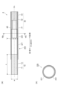
- FIG. 2 is a diagram showing an example of the configuration of the stick according to the first embodiment, where (a) is a vertical cross section and (b) is a diagram showing an example of a cross section taken along line Ib-Ib.
- FIG. 5 is a diagram showing a stick according to a comparative example of the stick 1 according to the first embodiment; (a) is a diagram showing a stick 1A according to a comparative example. (b) is a diagram showing a stick 1B according to a comparative example. (c) is a diagram showing a stick 1C according to a comparative example.
- FIG. 5 is a diagram showing a stick according to a comparative example of the stick 1 according to the first embodiment;
- (a) is a diagram showing a stick 1A according to a comparative example.
- (b) is a diagram showing a stick 1B according to a comparative example.
- (c) is a diagram showing a stick 1C according to a comparative example.
- FIG. 5 is a diagram showing a stick according to a comparative example of the stick 1 according to the first embodiment;
- (a) is a diagram showing a stick 1D according to a comparative example.
- (b) is a diagram showing a stick 1E according to a comparative example.
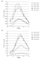
- FIG. 2 is a diagram showing delivery amounts of sticks 1A to 1E, where (a) shows the delivery amount of nicotine and (b) shows the delivery amount of glycerin.
- FIG. 8A is a view showing an example of the structure of a stick according to a second embodiment, where (a) is a longitudinal section and (b) is a view showing an example of a section taken along the VIb-VIb portion; It is a figure which shows the longitudinal cross-section of the stick which concerns on 3rd Embodiment.
- FIG. 1 is a view showing an example of the configuration of the stick according to the first embodiment, where (a) is a longitudinal section and (b) is a view showing an example of a section taken along line Ib-Ib.
- FIG. 2 is a schematic diagram schematically showing a configuration example of the suction device 100 according to the first embodiment.
- a non-combustion heating stick (hereinafter sometimes referred to as “stick”) 1 according to the first embodiment includes a base portion 10 , a cooling portion 20 and a filter portion 30 .
- the base material portion 10 is formed in a cylindrical shape.
- the direction of the centerline CL of the base member 10 may be referred to as the "centerline direction”.
- the stick 1 further includes a tipping paper 40 that integrates the base material portion 10, the cooling portion 20, and the filter portion 30 by winding them in order in the direction of the center line.
- a tipping paper 40 that integrates the base material portion 10, the cooling portion 20, and the filter portion 30 by winding them in order in the direction of the center line.
- one end side in the centerline direction (left side in FIG. 1) may be referred to as a first side
- the other end side in the centerline direction (right side in FIG. 1) may be referred to as a second side.
- the first side is the end side that is inserted into the suction device 100 .
- the second side is opposite to the first side and is the end side that the user holds in his/her mouth for suction.
- a cross section along the centerline direction is called a "longitudinal cross section", and a cross section taken along a plane perpendicular to the centerline direction is defined as a "transverse cross section".
- the suction device 100 includes a power supply unit 111 that accumulates power and supplies power to each component of the suction device 100, a sensor unit 112 that detects various information about the suction device 100, an information and a notification unit 113 for notifying the user of.
- the suction device 100 also includes a storage unit 114 for storing various information for the operation of the suction device 100, a communication unit 115 for transmitting and receiving information between the suction device 100 and other devices, and the suction device 100. and a control unit 116 for controlling overall internal operations.
- the suction device 100 also includes a heating unit 121 that heats the stick 1, a holding unit 140 that holds the stick 1, an opening 142 that communicates the internal space 141 with the outside, and other components of the suction device 100 from the heating unit 121. and a heat insulator 144 that prevents heat transfer to the element.
- the user performs suction while the stick 1 is held by the holding portion 140 .
- the heating part 121 heats the base material part 10 of the stick 1 .
- the heating part 121 is made of any material such as metal or polyimide.
- the heating part 121 is configured in a film shape and arranged so as to cover the outer periphery of the holding part 140 . Then, when the heating part 121 generates heat, the aerosol source 11 included in the stick 1 is heated from the outer circumference of the stick 1 .
- the heating unit 121 generates heat when supplied with power from the power supply unit 111 .
- power may be supplied when the sensor unit 112 detects that a predetermined user input has been performed. When the temperature of the stick 1 heated by the heating unit 121 reaches a predetermined temperature, the user can suck.
- the power supply may be stopped.
- power may be supplied and aerosol may be generated during a period in which the sensor unit 112 detects that the user has inhaled.
- the heat insulation part 144 is arranged so as to cover at least the outer periphery of the heating part 121 .
- the heat insulating part 144 is made of a vacuum heat insulating material, an airgel heat insulating material, or the like.
- a vacuum insulation material is, for example, a heat insulation material in which heat conduction due to gas is nearly zero by wrapping glass wool and silica (powder of silicon) in a resin film to create a high vacuum state. be.
- the base member 10 has an aerosol source 11 that generates vapor from which an aerosol is generated when heated, and a wrapping paper 12 that covers the outer periphery of the aerosol source 11 .
- the base material part 10 is formed in a cylindrical shape by winding the aerosol source 11 around the wrapping paper 12 .
- the aerosol source 11 may be tobacco-derived, such as, for example, tobacco cuts or tobacco raw materials molded into granules, sheets, or powder.
- the aerosol source 11 may also include non-tobacco sources made from plants other than tobacco, such as mints and herbs.
- the aerosol source 11 may contain perfume.
- the type of fragrance is not particularly limited, and menthol is particularly preferable from the viewpoint of imparting a good flavor.
- flavors may be used individually by 1 type, or may use 2 or more types together.
- the aerosol source 11 may contain a medicament for inhalation by the patient.
- the aerosol source 11 is not limited to solids, and may be polyhydric alcohols such as glycerin and propylene glycol, and liquids such as water. At least part of the base material portion 10 is housed in the internal space 141 of the holding portion 140 while the stick 1 is held by the holding portion 140 .
- the base material portion 10 formed by winding the aerosol source 11 with the wrapping paper 12 preferably has a cylindrical shape that satisfies a shape with an aspect ratio defined by Equation 1 of 1 or more.
- w is the width of the cross section of the base member 10
- h is the size of the base member 10 in the direction of the center line
- h ⁇ w is preferred.
- the shape of the cross section is not limited, and may be a polygon, a polygon with rounded corners, a circle, an ellipse, or the like. is the diameter of the circumscribed circle or the major axis of the circumscribed ellipse. It is preferable that the width of the cross section of the aerosol source 11 constituting the base material portion 10 is 4 mm or more and 9 mm or less.
- the size h of the base material portion 10 in the center line direction can be appropriately changed according to the size of the product. It is more preferable that it is above.
- the size h of the base material portion 10 in the center line direction is usually 70 mm or less, preferably 50 mm or less, more preferably 30 mm or less, and even more preferably 25 mm or less.
- the ratio of the size h of the base material part 10 to the size of the stick 1 is not particularly limited, but from the viewpoint of the balance between the delivery amount and the aerosol temperature, it is usually 10% or more, and 20%. It is preferably 25% or more, more preferably 30% or more.
- the ratio of the size h of the base material portion 10 to the size of the stick 1 is usually 80% or less, preferably 70% or less, more preferably 60% or less, and 50% or less. 45% or less is particularly preferable, and 40% or less is most preferable.
- the content of the aerosol source 11 in the base material portion 10 is not particularly limited, but may be 200 mg or more and 800 mg or less, preferably 250 mg or more and 600 mg or less. This range is particularly suitable for the base member 10 with a circumference of 22 mm and a size of 20 mm in the centerline direction.
- the cut tobacco material contained in the aerosol source 11 is not particularly limited, and known materials such as lamina and backbone can be used.
- dried tobacco leaves are pulverized to an average particle size of 20 ⁇ m or more and 200 ⁇ m or less to obtain pulverized tobacco, which is homogenized and processed into a sheet (hereinafter simply referred to as a homogenized sheet). It can be anything.
- a homogenizing sheet having a size approximately equal to the size in the center line direction of the base material part 10 is chopped substantially horizontally with the center line direction of the base material part 10, and the aerosol source 11 is filled with the so-called strand. can be a type.
- the width of the chopped tobacco is preferably 0.5 mm or more and 2.0 mm or less for filling the aerosol source 11 .
- отно ⁇ еским can be used for the tobacco leaves used for producing the cut tobacco and the homogenized sheet.
- examples include yellow, burley, oriental, landrace, other Nicotiana-tabacum varieties, Nicotiana-Rustica varieties, and mixtures thereof.
- the mixture can be appropriately blended and used so as to obtain the desired taste. Details of tobacco varieties are disclosed in "Tobacco Encyclopedia, Tobacco Research Center, March 31, 2009".
- There are a number of conventional methods for producing homogenized sheets that is, methods for pulverizing tobacco leaves and processing them into homogenized sheets. The first is a method of producing a papermaking sheet using a papermaking process.
- the second method is to mix pulverized tobacco leaves with an appropriate solvent such as water to homogenize the mixture, and then thinly cast the homogenized product on a metal plate or metal plate belt and dry it to produce a cast sheet.
- a third method is to prepare a rolled sheet by mixing a suitable solvent such as water with pulverized tobacco leaves, homogenizing the mixture, and extruding the mixture into a sheet. Details of the types of homogenizing sheets are disclosed in "Encyclopedia of Tobacco, Tobacco Research Center, March 31, 2009".
- the water content of the aerosol source 11 can be 10% by mass or more and 15% by mass or less, preferably 11% by mass or more and 13% by mass or less, relative to the total amount of the aerosol source 11 . Such a water content suppresses the occurrence of winding stains, and improves the winding suitability of the base material portion 10 during manufacturing.
- the aerosol source 11 is not particularly limited, and may contain extracts from various natural products and/or constituents thereof, depending on the application. Extractable substances and/or constituents thereof may include glycerin, propylene glycol, triacetin, 1,3-butanediol, and mixtures thereof.
- the content of the extracting substance and/or its constituent components in the aerosol source 11 is not particularly limited, and from the viewpoint of sufficiently generating an aerosol and imparting a good flavor, it is usually It is 5% by mass or more, preferably 10% by mass or more.
- the content of the extractable substance and/or its constituent components in the aerosol source 11 is usually 50% by mass or less, preferably 15% by mass or more and 25% by mass or less.
- the packing density of the aerosol source 11 is not particularly limited, but is usually 250 mg/cm 3 or more, preferably 300 mg/cm 3 or more, from the viewpoint of securing the performance of the stick 1 and imparting a good flavor. Also, the packing density in the aerosol source 11 is usually 400 mg/cm 3 or less, preferably 350 mg/cm 3 or less.
- the aerosol source 11 may be composed of a tobacco sheet.
- the number of tobacco sheets may be one, or two or more.
- the aerosol source 11 is composed of one tobacco sheet
- a tobacco sheet having one side of a size approximately equal to the size in the center line direction of the object to be filled is used as the object to be filled.
- a filling mode (so-called gathered sheet) is exemplified in a state in which the sheet is folded back multiple times horizontally with respect to the center line direction of the sheet.
- a tobacco sheet having one side of which is approximately the same size as the centerline direction of the object to be filled is wound in a direction orthogonal to the centerline direction of the object to be filled. mentioned.
- the aerosol source 11 is composed of two or more tobacco sheets, for example, a plurality of tobacco sheets each having a size approximately equal to the size in the center line direction of the object to be filled
- a mode in which the material is wound in a direction orthogonal to the center line direction of the material to be filled so as to be arranged concentrically is exemplified.
- Concentrically arranged means that the centers of all the tobacco sheets are arranged at approximately the same position.
- Two or more tobacco sheets may all have the same composition or physical properties, or a part or all of each tobacco sheet may have different compositions or physical properties. Moreover, the thickness of each tobacco sheet may be the same or different. The thickness of each tobacco sheet is not limited, but is preferably 150 ⁇ m or more and 1000 ⁇ m or less, more preferably 200 ⁇ m or more and 600 ⁇ m or less, in terms of balance between heat transfer efficiency and strength.
- the aerosol source 11 prepares a plurality of tobacco sheets having different widths, prepares a laminated body in which the width decreases from the first side to the second side, passes the laminated body through a winding tube, and winds and forms the laminated body. It can be manufactured by According to this manufacturing method, the plurality of tobacco sheets extend in the centerline direction and are arranged concentrically around CL.
- the laminate is preferably prepared so that a non-contact portion is formed between adjacent tobacco sheets after roll-forming. If there is a non-contact portion (gap) between the plurality of tobacco sheets, which is not in contact with the tobacco sheets, the flavor flow path can be secured and the delivery efficiency of the flavor component can be enhanced. On the other hand, since the heat from the heater can be transferred to the outer tobacco sheets through the contact portions of the plurality of tobacco sheets, high heat transfer efficiency can be ensured.
- an embossed tobacco sheet is used, adjacent tobacco sheets are laminated without bonding the entire surfaces of adjacent tobacco sheets, and adjacent tobacco sheets are stacked together.
- the entire or part of the adjacent tobacco sheets are lightly adhered so that they can be separated after roll-forming, thereby preparing a laminate.
- the wrapping paper 12 may be arranged on the end surface of the first side of the laminate.
- the packing density of the aerosol source 11 is not particularly limited, but is usually 250 mg/cm 3 or more, preferably 300 mg/cm 3 or more, from the viewpoint of securing the performance of the stick 1 and imparting a good flavor. Also, the packing density of the aerosol source 11 is usually 400 mg/cm 3 or less, preferably 350 mg/cm 3 or less.
- Polyols such as glycerin, propylene glycol, and 1,3-butanediol may be added to tobacco sheets.
- the amount added to the tobacco sheet is preferably 5% by mass or more and 50% by mass or less, more preferably 15% by mass or more and 25% by mass or less, relative to the dry mass of the tobacco sheet.
- Tobacco sheets can be appropriately manufactured by known methods such as paper making, slurrying, and rolling. Note that the uniformizing sheet described above can also be used.
- papermaking it can be manufactured by a method including the following steps. 1) Dry tobacco leaves are crushed and extracted with water to separate the water extract and residue. 2) Dry and concentrate the water extract under reduced pressure. 3) Pulp is added to the residue, fiberized with a refiner, and then paper is made. 4) A concentrated solution of the water extract is added to the paper sheet and dried to obtain a tobacco sheet. In this case, a step of removing some components such as nitrosamines may be added (see JP-T-2004-510422).
- the slurry method it can be produced by a method including the following steps.
- a non-woven tobacco sheet manufactured by a method including the following steps can also be used. 1) Mix powdered tobacco leaves and a binder. 2) The mixture is sandwiched between non-woven fabrics. 3) Forming the laminate into a certain shape by heat welding to obtain a non-woven tobacco sheet.
- the types of raw material tobacco leaves used in each of the above methods may be the same as those described for the aerosol source 11 containing cut tobacco.
- the composition of the tobacco sheet is not particularly limited, for example, the content of the tobacco raw materials (tobacco leaves) is preferably 50% by mass or more and 95% by mass or less with respect to the total mass of the tobacco sheet.
- the tobacco sheet may also contain a binder, and examples of such binders include guar gum, xanthan gum, carboxymethylcellulose, sodium salts of carboxymethylcellulose, and the like.
- the amount of the binder is preferably 1% by mass or more and 10% by mass or less with respect to the total mass of the tobacco sheet.
- the tobacco sheet may further contain other additives. Examples of additives include fillers such as pulp.
- the structure of the wrapping paper 12 used for the base material portion 10 is not particularly limited, and can be a general form, for example, one containing pulp as a main component.
- pulp in addition to wood pulp such as softwood pulp and hardwood pulp, non-wood pulp such as flax pulp, hemp pulp, sisal pulp, and esparto, which are generally used for wrapping paper 12 for tobacco products, can be used. It may be obtained by mixing and manufacturing.
- the types of pulp that can be used include chemical pulp, ground pulp, chemi-grand pulp, thermomechanical pulp, and the like prepared by kraft cooking, acid/neutral/alkaline sulfite cooking, soda salt cooking, and the like.
- the winding paper 12 is manufactured by preparing and uniforming the texture in the papermaking process using a fourdrinier paper machine, a cylinder paper machine, a circular and short composite paper machine, and the like. If necessary, a wet strength agent may be added to impart water resistance to the wrapping paper 12, or a sizing agent may be added to adjust the printing condition of the wrapping paper 12. Furthermore, aluminum sulfate, various anionic, cationic, nonionic or amphoteric retention improvers, drainage improvers, papermaking internal additives such as paper strength agents, and dyes, pH adjusters, Papermaking additives such as antifoam agents, pitch control agents, and slime control agents can be added.
- the basis weight of the base paper for the wrapping paper 12 is, for example, usually 20 gsm or more, preferably 25 gsm or more. On the other hand, the basis weight is usually 65 gsm or less, preferably 50 gsm or less, more preferably 45 gsm or less.
- the thickness of the wrapping paper 12 is not particularly limited, and is usually 10 ⁇ m or more, preferably 20 ⁇ m or more, more preferably 30 ⁇ m or more, from the viewpoints of rigidity, air permeability, and ease of adjustment during paper production.
- the thickness of the wrapping paper 12 is usually 100 ⁇ m or less, preferably 75 ⁇ m or less, more preferably 50 ⁇ m or less.
- the shape of the wrapping paper 12 for producing the base material part 10 can be square or rectangular.
- the length of one side can be about 12 mm or more and 70 mm or less. , and a more preferable length is about 23 mm.
- the aerosol source 11 is wound with the wrapping paper 12 in a cylindrical shape, for example, in the circumferential direction, the end of the wrapping paper 12 and the end of the wrapping paper 12 on the opposite side are overlapped by about 2 mm and glued to form a cylindrical paper. It has the shape of a tube in which the aerosol source 11 is filled.
- the size of the rectangular wrapping paper 12 can be determined by the size of the base material portion 10 .
- the paper wrapper 12 may also contain fillers.
- the content of the filler can be 10% by mass or more and less than 60% by mass, preferably 15% by mass or more and 45% by mass or less, based on the total mass of the wrapping paper 12 .
- the filler content is preferably 15% by mass or more and 45% by mass or less in a preferable basis weight range (25 gsm or more and 45 gsm or less).
- the filler content is preferably 15 mass % or more and 45 mass % or less, and when the basis weight is 35 gsm or more and 45 gsm or less, the filler content is 25 mass % or more. It is preferably 45% by mass or less.
- a filler calcium carbonate, titanium dioxide, kaolin, and the like can be used, but from the viewpoint of enhancing flavor and whiteness, it is preferable to use calcium carbonate.
- auxiliary agents other than base paper and fillers may be added to the wrapping paper 12.
- a water resistance improver may be added to improve water resistance.
- Water resistance improvers include wet strength agents (WS agents) and sizing agents.
- wet strength agents include urea formaldehyde resin, melamine formaldehyde resin, polyamide epichlorohydrin (PAE), and the like.
- sizing agents include rosin soap, alkyl ketene dimer (AKD), alkenyl succinic anhydride (ASA), and highly saponified polyvinyl alcohol having a degree of saponification of 90% or more.
- a paper strength agent may be added, and examples thereof include polyacrylamide, cationic starch, oxidized starch, CMC, polyamide epichlorohydrin resin, polyvinyl alcohol, and the like.
- polyacrylamide, cationic starch, oxidized starch, CMC, polyamide epichlorohydrin resin, polyvinyl alcohol, and the like examples thereof include polyacrylamide, cationic starch, oxidized starch, CMC, polyamide epichlorohydrin resin, polyvinyl alcohol, and the like.
- a coating agent may be added to at least one of the front and back sides of the wrapping paper 12 .
- the coating agent is not particularly limited, but a coating agent capable of forming a film on the paper surface and reducing liquid permeability is preferred.
- alginic acid and its salts e.g. sodium salts
- polysaccharides such as pectin
- cellulose derivatives such as ethyl cellulose, methyl cellulose, carboxymethyl cellulose, nitrocellulose
- starch and derivatives thereof e.g. carboxymethyl starch, hydroxyalkyl starch and cationic starch
- ether derivatives such as starch acetate, starch phosphate and ester derivatives such as starch octenylsuccinate).
- the cooling unit 20 is arranged adjacent to the base material unit 10 and the filter unit 30, and is provided in the molding paper 21 which is cylindrically molded so that the cross section is hollow (cavity). and a heat exchanger 22 .
- Forming paper 21 has openings V through which air flows from the outside to the inside.
- the heat exchanging material 22 is provided on the side opposite to the base material portion 10 with respect to the opening V. As shown in FIG.
- the size of the cooling part 20 in the centerline direction can be appropriately changed according to the size of the product, but it is usually 5 mm or more, preferably 10 mm or more, and more preferably 15 mm or more. Also, the size of the cooling part 20 in the center line direction is usually 35 mm or less, preferably 30 mm or less, and more preferably 25 mm or less. By setting the size of the cooling unit 20 in the center line direction to the above-described lower limit or more, it is possible to secure a sufficient cooling effect and obtain a good flavor. It is possible to suppress the loss caused by the aerosol adhering to the forming paper 21 .
- the forming paper 21 is cylindrical, and its inner diameter can be appropriately changed according to the size of the product.
- the inner diameter of the forming paper 21 is preferably substantially the same as the inner diameter of the wrapping paper 12 .
- This "substantially identical" means, for example, a difference of about two layers of the wrapping paper 12 or the forming paper 21, a difference within 1 mm from the outer diameter of the aerosol source 11, preferably within 0.5 mm, a difference within 1 mm from the inner diameter of the wrapping paper 12, Preferably, a difference within 0.5 mm is regarded as substantially the same.
- the thickness of the molding paper 21 is not particularly limited, and may be, for example, 5 ⁇ m or more and 500 ⁇ m or less, or 10 ⁇ m or more and 250 ⁇ m or less.
- the material of the forming paper 21 is not particularly limited.
- pulp may be the main component, and polyethylene, polypropylene, polyvinyl chloride, polyethylene terephthalate, polylactic acid, cellulose acetate, and aluminum foil may be used. It may be a caustic-based one, or any combination thereof.
- the forming paper 21 may be formed by a thin sheet of material that is crumpled to form channels and then pleated, gathered and folded to increase the inner surface area. .
- the cooling part 20 is provided with a plurality of openings V (also called “ventilation filter (Vf)" in this technical field) concentrically and circumferentially.
- the aperture V is a hole penetrating the forming paper 21 .
- the shape of the hole can be exemplified by a polygon, a polygon with rounded corners, a circle, an ellipse, or the like.
- the opening V exists in a region where air can flow from the outside of the stick 1 , in other words, in a region where the stick 1 is held by the holding portion 140 of the suction device 100 and protrudes from the opening 142 .
- the cooling unit 20 Due to the presence of the openings V, air flows into the inside of the forming paper 21 of the cooling unit 20 from the outside during suction, and the temperature of steam and air flowing in from the base material unit 10 can be lowered. Furthermore, by setting the position where the cooling unit 20 is provided within a region of 4 mm or more in the direction of the cooling unit 20 from the boundary between the cooling unit 20 and the filter unit 30, not only the cooling capacity is improved, but also the heat generated by heating It is possible to suppress the retention of the substance (product) in the cooling unit 20 and improve the delivery amount of the product. Then, when the base material portion 10 is heated, the vapor generated with the aerosol as the condensation nucleus is liquefied by contacting the air from the outside and the temperature is lowered, thereby promoting the generation of the aerosol. .
- the number of hole groups may be one, or two or more.
- the number of hole groups may be one, or two or more.
- there are two or more hole groups from the viewpoint of improving the delivery amount of the component generated by heating, from the boundary between the cooling unit 20 and the filter unit 30, in the region of less than 4 mm in the direction of the cooling unit 20 side It is preferable not to provide an aperture group.
- the tip paper 40 has the openings V provided in the cooling portion 20. It is preferable that the opening V is provided at the position directly above.
- a chip paper 40 having holes V overlapping the holes V may be prepared and wound. It is preferable to make a hole through the cooling part 20 and the tipping paper 40 at the same time after making the non-stick stick 1 .
- the region where the opening V exists is not particularly limited as long as it is a region of 4 mm or more in the direction of the cooling unit 20 from the boundary between the cooling unit 20 and the filter unit 30 from the viewpoint of improving the product delivery by heating.
- the area is preferably 4.5 mm or more, more preferably 5 mm or more, and even more preferably 5.5 mm or more.
- the region where the opening V exists is preferably a region of 15 mm or less, more preferably 10 mm or less, from the boundary between the cooling unit 20 and the filter unit 30.
- the area is 7 mm or less, more preferably.
- the region where the opening V exists is preferably a region of 16 mm or less from the boundary between the cooling part 20 and the base material part 10, and 15.5 mm or less. , more preferably 15 mm or less, and particularly preferably 14.5 mm or less.
- the apertures V are provided so that the ratio of air inflow through the apertures V is 10% by volume or more and 90% by volume or less when sucked at 17.5 ml/sec by an automatic smoking machine.
- This "air inflow ratio” is the volume ratio of the air that has flowed in from the opening V when the ratio of the air sucked from the mouth end is 100% by volume.
- the air inflow ratio is preferably 50% by volume or more and 80% by volume or less, more preferably 55% by volume or more and 75% by volume or less.
- the number of holes V per hole group is selected from a range of 5 to 50, and the diameter of the holes V is set to a range of 0.1 mm to 0.5 mm. can be selected from and achieved by a combination of these selections.
- the air inflow rate can be measured by a method conforming to ISO9512 using a winding quality measuring instrument (eg, SODIMAX D74/SODIM manufactured by SAS).
- the heat exchange material 22 is a material that can exchange heat with the aerosol passing through the cooling unit 20 or a material that can add fragrance to the aerosol.
- the heat exchanging material 22 is provided inside the cylindrical forming paper 21 of the cooling section 20 on the opposite side of the opening V from the substrate section 10 .
- the heat exchanging material 22 preferably includes a cooling element that undergoes a phase transition at the temperature inside the cooling section 20 to absorb heat. Thereby, the heat exchange material 22 can promote cooling of the aerosol passing through the cooling section 20 .
- the heat exchange material 22 preferably contains a fragrance from the viewpoint of imparting a good smoking taste to the aerosol. Accordingly, when the heat exchange material 22 is applied to the inside of the forming paper 21, for example, the aerosol passing through the cooling section 20 can be imparted with a flavor, or in other words, can be scented.
- the type of cooling element is not particularly limited, but biodegradable polymers and edible polymers are preferred.
- the glass transition temperature of the cooling element is preferably 400° C. or lower, more preferably 200° C. or lower, from the viewpoint of allowing the cooling element to undergo a phase transition and endotherm at the temperature in the cooling unit 20 .
- the temperature is preferably 100° C. or lower, and more preferably 100° C. or lower.
- the lower limit of the glass transition temperature of the cooling element is not particularly limited, it is, for example, 40° C. or higher.
- the glass transition temperature of the cooling element is specifically a value measured with a differential scanning calorimeter (trade name: "DSC7000", manufactured by Hitachi High-Tech Science). Further, from the viewpoint of easily obtaining a cooling effect by adsorbing water vapor in the aerosol, it is preferable that the affinity with water is high.
- cooling elements include polylactic acid, polyvinyl alcohol (PVA), cellulose acetate, trehalose, maltose, sucrose, maltitol, glucose, wax, wax, hydrogenated oil, and the like. These may be used alone or in combination of two or more.
- PVA polyvinyl alcohol
- POVACOAT polyvinyl alcohol/acrylic acid/methyl methacrylate copolymer
- the heat exchange material 22 preferably contains a perfume component, and more preferably contains the perfume component in the cooling element.
- the cooling element of the heat exchange material 22 provided in the molding paper 21 contains a perfume component
- the perfume component is held in the polymer, so volatilization of the perfume component before use can be suppressed.
- part of the heat exchange material 22 becomes rubbery or melts, gradually releasing the perfume component from the cooling element.
- the perfume component can be stably supplied throughout the inhalation.
- the fragrance component is contained in the cooling unit 20
- the amount of heat in the aerosol is absorbed by vaporization, sublimation, etc. of the fragrance component, and a cooling effect can be expected.
- the types of flavor components are not particularly limited, and from the viewpoint of imparting a good smoking taste, acetoanisole, acetophenone, acetylpyrazine, 2-acetylthiazole, alfalfa extract, amyl alcohol, amyl butyrate, trans-anethole, star anise oil.
- apple juice Peruvian balsam oil, beeswax absolute, benzaldehyde, benzoin resinoids, benzyl alcohol, benzyl benzoate, benzyl phenylacetate, benzyl propionate, 2,3-butanedione, 2-butanol, butyl butyrate, butyric acid, caramel, cardamom oil.
- carob absolute ⁇ -carotene, carrot juice, L-carvone, ⁇ -caryophyllene, cassia bark oil, cedarwood oil, celery seed oil, chamomile oil, cinnamaldehyde, cinnamic acid, cinnamyl alcohol, cinnamyl cinnamate, citronella Oil, DL-citronellol, clary sage extract, cocoa, coffee, cognac oil, coriander oil, cumin aldehyde, davana oil, ⁇ -decalactone, ⁇ -decalactone, decanoic acid, dill herb oil, 3,4-dimethyl-1,2 -cyclopentanedione, 4,5-dimethyl-3-hydroxy-2,5-dihydrofuran-2-one, 3,7-dimethyl-6-octenoic acid, 2,3-dimethylpyrazine, 2,5-dimethylpyrazine , 2,6-
- Extract rose oil, rum, sage oil, sandalwood oil, spearmint oil, styrax absolute, marigold oil, tea distillate, ⁇ -terpineol, terpinyl acetate, 5,6,7,8-tetrahydroquinoxaline, 1 ,5,5,9-tetramethyl-13-oxacyclo(8.3.0.0(4.9))tridecane, 2,3,5,6-tetramethylpyrazine, thyme oil, tomato extract, 2- tridecanone, triethyl citrate, 4-(2,6,6-trimethyl-1-cyclohexenyl)2-buten-4-one, 2,6,6-trimethyl-2-cyclohexene-1,4-dione, 4- (2,6,6-trimethyl-1,3-cyclohexadienyl)2-buten-4-one, 2,3,5-trimethylpyrazine, ⁇ -undecalactone, ⁇ -valerolactone, vanilla extract, vanillin , vera
- the heat exchange article 22 is formed by a thin sheet of material that is creased, pleated, gathered and folded to ensure an aerosol passageway 22a extending in the direction of the centerline. is provided as follows. More folds or folds in the heat exchange article 22 increase the total surface area of the heat exchange article 22 .
- the heat exchange material 22 is preferably in the form of a sheet having grooves extending in the centerline direction. Since the heat exchange article 22 has grooves extending in the centerline direction, the surface area of the heat exchange article 22 can be increased while improving the permeability of the aerosol in the second lateral direction.
- the number of grooves formed in the heat exchanging material 22 is not particularly limited.
- the sheet-shaped heat exchange material 22 includes, for example, a sheet made of cooling elements, and cooling coated paper including paper and a cooling layer including cooling elements provided on the paper.
- the cooling layer may be provided only on one surface of the cooling coated paper, or may be provided on both surfaces of the cooling coated paper.
- the cooling coated paper is not particularly limited as long as it functions as a support.
- the thickness of the cooling layer is not particularly limited.
- the sheet-like heat exchange material 22 may be one, or two or more.
- the folds or pleats may be omitted as long as the passage path 22a for the aerosol extending in the centerline direction is secured.
- the sheet-shaped heat exchange material 22 may be cut into strips or strands (strings).
- the filter section 30 has a first filter 31 connected to the second side of the cooling section 20 and a second filter 32 located on the second side of the first filter 31 .
- the first filter 31 has a hollow cross section and the second filter 32 has a solid cross section.
- the second end of the cooling section 20 and the first end of the filter section 30 are wound integrally using chip paper 40, which will be described later, so that they are connected (connected). ) is done.
- a roll paper 33 may be wound between the outer peripheral surfaces of the first filter 31 and the second filter 32 and the tip paper 40 .
- the cross section of the first filter 31 and the second filter 32 of the filter part 30 is substantially circular, and the diameter of the circle can be changed appropriately according to the size of the product, but is usually 4.0 mm or more and 9.0 mm. It is preferably 4.5 mm or more and 8.5 mm or less, more preferably 5.0 mm or more and 8.0 mm or less. If the cross section is not circular, the above diameter is assumed to be a circle having the same area as that of the cross section, and the diameter of that circle is applied.
- the length of the perimeter of the cross section of the first filter 31 and the second filter 32 of the filter part 30 can be appropriately changed according to the size of the product, but it is usually 14.0 mm or more and 27.0 mm or less, and 15.0 mm It is preferably 26.0 mm or more, and more preferably 16.0 mm or more and 25.0 mm or less.
- the size of the filter part 30 in the center line direction can be appropriately changed according to the size of the product. More preferably, it is 15.0 mm or more and 25.0 mm or less.
- the shape and dimensions of the first filter 31 and the second filter 32 can be appropriately adjusted so that the shape and dimensions of the filter section 30 fall within the above ranges.
- the ventilation resistance per 120 mm of the size of the filter part 30 in the center line direction is not particularly limited, but is usually 40 mmH 2 O or more and 300 mmH 2 O or less, preferably 70 mmH 2 O or more and 280 mmH 2 O or less, It is more preferably 90 mmH 2 O or more and 260 mmH 2 O or less.
- the airflow resistance is measured according to the ISO standard method (ISO6565) using, for example, a Cerulean filter airflow resistance meter.
- the airflow resistance of the filter section 30 is determined by the air flow rate (17.5 cc/min) when air is flown from the first side to the second side in a state in which air does not pass through the side surface of the filter section 30. Refers to the pressure difference between the first side and the second side. Units are generally expressed in mmH2O .
- the first filter 31 and the second filter 32 are not particularly limited as long as they contain filter materials and have general filter functions.
- General functions of filters include, for example, adjusting the amount of air mixed when inhaling aerosols, etc., reducing flavor, reducing nicotine and tar, etc., but having all of these functions is not possible. don't need it.
- the non-combustion heating stick 1 which tends to produce fewer components and a lower filling rate of the aerosol source 11 than cigarette products, the aerosol source 11 falls off while suppressing the filtering function. It is also one of the important functions to prevent
- the filter material that constitutes the first filter 31 and the second filter 32 is, for example, a cylinder shaped filler such as cellulose acetate fiber, non-woven fabric, or pulp paper. Moreover, the aspect using the paper filter filled with the sheet-like pulp paper may be sufficient.
- the density of the filter material is not particularly limited, it is usually 0.10 g/cm 3 or more and 0.25 g/cm 3 or less, preferably 0.11 g/cm 3 or more and 0.24 g/cm 3 or less. More preferably, it is 0.23 g/cm 3 or more and 0.23 g/cm 3 or less.
- the form of web 33 is not particularly limited, and may include one or more rows of adhesive-containing seams.
- the adhesive may comprise a hot melt adhesive, and the hot melt adhesive may comprise polyvinyl alcohol.
- the filter part 30 consists of two or more members, it is preferable that the roll paper is wound together with these two or more members.
- the material of the paper roll 33 is not particularly limited, and known materials can be used, and it may contain a filler such as calcium carbonate.
- the thickness of the paper roll 33 is not particularly limited, and is usually 20 ⁇ m or more and 140 ⁇ m or less, preferably 30 ⁇ m or more and 130 ⁇ m or less, and more preferably 30 ⁇ m or more and 120 ⁇ m or less.
- the basis weight of the paper roll 33 is not particularly limited, and is usually 20 gsm or more and 100 gsm or less, preferably 22 gsm or more and 95 gsm or less, and more preferably 23 gsm or more and 90 gsm or less.
- the paper roll 33 may or may not be coated, but is preferably coated with a desired material from the viewpoint of imparting functions other than strength and structural rigidity.
- the configuration of the tipping paper 40 is not particularly limited, and can be in a general form, and for example, can include pulp as a main component.
- pulp in addition to being made from wood pulp such as softwood pulp and hardwood pulp, non-wood pulp such as flax pulp, hemp pulp, sisal pulp, and esparto, which are generally used for cigarette paper, are mixed. and obtained by manufacturing. These pulps may be used alone or in combination of multiple types at any ratio.
- the tipping paper 40 may be composed of one sheet, or may be composed of a plurality of sheets or more.
- As the form of pulp chemical pulp, ground pulp, chemi-grand pulp, thermomechanical pulp, etc.
- the chip paper 40 may be manufactured by the above-described manufacturing method or may be a commercially available product.
- the shape of the tipping paper 40 is not particularly limited, and can be square or rectangular, for example.
- the basis weight of the tipping paper 40 is not particularly limited, but is usually 32 gsm to 60 gsm, preferably 33 gsm to 55 gsm, more preferably 34 gsm to 53 gsm.
- the air permeability of the tipping paper 40 is not particularly limited, it is generally 0 Coresta unit or more and 30000 Coresta unit or less, and preferably more than 0 Coresta unit and 10000 Coresta unit or less. Air permeability is a value measured in accordance with ISO 2965:2009, and is expressed as the flow rate (cm 3 ) of gas passing through an area of 1 cm 2 per minute when the pressure difference between both sides of the paper is 1 kPa. be done.
- One Coresta unit (1 Coresta unit, 1 CU) is cm 3 /(min ⁇ cm 2 ) under 1 kPa.
- the chipping paper 40 may contain fillers other than the above pulp, for example, metal carbonates such as calcium carbonate and magnesium carbonate, metal oxides such as titanium oxide, titanium dioxide and aluminum oxide, barium sulfate, metal sulfates such as calcium sulfate, metal sulfides such as zinc sulfide, quartz, kaolin, talc, diatomaceous earth, gypsum, etc.; preferably contains These fillers may be used singly or in combination of two or more.
- the chipping paper 40 may contain various auxiliary agents, for example, a water resistance improver to improve water resistance.
- Water resistance improvers include wet strength agents (WS agents) and sizing agents.
- wet strength agents include urea formaldehyde resin, melamine formaldehyde resin, polyamide epichlorohydrin (PAE), and the like.
- sizing agents include rosin soap, alkyl ketene dimer (AKD), alkenyl succinic anhydride (ASA), and highly saponified polyvinyl alcohol having a degree of saponification of 90% or more.
- a coating agent may be added to at least one of the front and back sides of the tip paper 40 .
- the coating agent is not particularly limited, but a coating agent capable of forming a film on the paper surface and reducing liquid permeability is preferred.
- a portion of the outer surface of the tipping paper 40 may be covered with a rip release material.
- the lip release material is configured to assist when the user mouths the filter portion 30 of the stick 1 so that the contact between the lips and the tipping paper 40 is easily released without substantially sticking.
- Lip release materials may include, for example, ethyl cellulose, methyl cellulose, and the like.
- the outer surface of the tipping paper 40 may be coated with a rip release material by applying an ethylcellulose-based or methylcellulose-based ink to the outer surface of the tipping paper 40 .
- FIGS. 3A, 3B, and 3C are diagrams showing sticks according to comparative examples of the stick 1 according to the first embodiment.
- (a) is a diagram showing a stick 1A according to a comparative example.
- (b) is a diagram showing a stick 1B according to a comparative example.
- (c) is a diagram showing a stick 1C according to a comparative example.
- 4A and 4B are diagrams showing sticks according to comparative examples of the stick 1 according to the first embodiment.
- FIGS. 5(a) and 5(b) are diagrams showing delivery amounts of sticks 1A to 1E, where (a) shows the delivery amount of nicotine and (b) shows the delivery amount of glycerin.
- members corresponding to the base member 10 are base members 10A to 10E
- members corresponding to the cooling member 20 are cooling members 20A to 20E
- members corresponding to the filter member 30 are filter members 30A to 30E
- members corresponding to the tip paper 40 are tip papers 40A to 40E.
- the wrapping papers 12A to 12E of the base material portions 10A to 10E and the forming papers 21A to 21E of the cooling portions 20A to 20E are the same as the wrapping paper 12 and the forming paper 21, respectively.
- the paper rolls 33A to 33E and the tip papers 40A to 40E of the filter units 30A to 30E are the same as the paper roll 33 and the tip paper 40, respectively.
- the stick 1A differs from the stick 1 in that the heat exchanging material 22 is not provided, as shown in FIG. 3(a).
- the stick 1B differs from the stick 1 in that the heat exchange material 22 is not provided and the cooling section 20B and the mouthpiece end are communicated with each other.
- the stick 1C is provided with a heat exchange material 22C on the side of the base portion 10C (first side) with respect to the opening V with respect to the stick 1, and The difference is that the cooling part 20C and the mouth end are communicated with each other.
- sticks 1D and 1E differ from stick 1 in that cooling portions 20D and 20E are communicated with the mouth end.
- aerosol source 11A of base portion 10A contains menthol.
- the filter section 30A has a first filter 31A corresponding to the first filter 31 of the stick 1 and a second filter 32A corresponding to the second filter 32 of the stick 1.
- aerosol source 11B of base portion 10B contains menthol.
- the filter part 30B has a first filter 31B corresponding to the first filter 31 of the stick 1 and a cylindrical second filter 32B unlike the second filter 32 of the stick 1 .
- aerosol source 11C of base portion 10C does not contain menthol.
- the cooling part 20C is provided with a heat exchange material 22C containing menthol and PVA on the side of the base material part 10C with respect to the opening V. As shown in FIG. Further, the filter section 30C has a cylindrical first filter 31C.
- aerosol source 11D of base portion 10D contains menthol.
- the cooling part 20D is provided with a heat exchanging material 22D containing PVA on the side (second side) of the opening V opposite to the base part 10D.
- the filter section 30D has a cylindrical first filter 31D.
- aerosol source 11E of substrate portion 10E does not contain menthol.
- the cooling part 20E is provided with a heat exchanging material 22E containing menthol and PVA on the opposite side of the opening V to the base material part 10E.
- the filter section 30E has a cylindrical first filter 31E.
- the horizontal axis shows the number of puffs (suction) of the stick 1, and the delivery amounts of nicotine and glycerin were measured for each suction.
- the heating by the suction device 100 was carried out by setting the target temperature of the heating unit 121 to 280 degrees from the non-heating state, heating for 15 seconds, and then keeping the target temperature constant at 260 degrees. Note that 15 seconds corresponds to the time it takes to reach 280° C. when the heating unit 121 starts heating from a non-heated state, in other words, a state where the heating unit 121 is at an ambient temperature (for example, room temperature).
- the puffing conditions for measuring the delivery amount are as follows.
- the suction volume was 55 ml
- the suction time was 2 seconds for 1 puff
- the suction interval was 30 seconds. It should be noted that the measurement was performed while the aperture V was open.
- the stick 1A and the stick 1B differ in that the filter portion 30A has a solid second filter 32A, whereas the filter portion 30B is entirely hollow, and the cooling portions 20A and 20B are provided with the heat exchange material 22. They are the same in that they are not Here, cooling in the hollow cooling part 20 means cooling to the extent that the vapor is liquefied and an aerosol is generated.
- cooling in the hollow cooling part 20 means cooling to the extent that the vapor is liquefied and an aerosol is generated.
- the cross sections of the first filter 31B and the second filter 32B are hollow, so the user directly inhales the aerosol generated in the cooling section 20B. Therefore, the temperature of the aerosol inhaled by the user is high, and the user may feel uncomfortable.
- the second filter 32A of the stick 1A is solid, heat exchange between the second filter 32A and the aerosol makes the temperature of the aerosol lower than that of the stick 1B.
- the delivery amount of nicotine and glycerin in the stick 1A through the second filter 32A in which the aerosol is solid is Less than stick 1B through 32B.
- stick 1A can lower the temperature of the aerosol inhaled by the user than stick 1B, but delivers less nicotine and glycerin than stick 1B.
- the stick 1C is different from the stick 1B in that a heat exchanging material 22C is provided inside the forming paper 21C of the cooling portion 20C, and is the same in that the filter portion 30C is entirely hollow.
- the heat exchange material 22C contains PVA that undergoes a phase transition and absorbs heat upon contact with the vapor generated by heating the base material portion 10C. Therefore, stick 1C facilitates vapor and aerosol cooling, and the temperature of the aerosol inhaled by the user is lower than stick 1B. Further, the stick 1C differs from the stick 1A in that the heat exchange material 22C is provided inside the forming paper 21C of the cooling portion 20C and that the filter portion 30C is entirely hollow.
- the heat exchange material 22C contains PVA, which is superior in endothermic properties to general filter materials. Therefore, stick 1C promotes vapor and aerosol cooling more than passing through a solid filter, and the temperature of the aerosol inhaled by the user is lower than stick 1A.
- stick 1C since the stick 1C is provided with the heat exchange material 22C inside the forming paper 21C of the cooling part 20C, the steam generated by heating the base material part 10C is condensed into the heat exchange material 22C. . Therefore, as shown in FIGS. 5(a) and (b), stick 1C delivers less nicotine and glycerin than stick 1B.
- the stick 1C cools the vapor and the aerosol by the heat exchange material 22C before the vapor is sufficiently liquefied and the aerosol is generated, the vapor containing nicotine and glycerin passes through the water molecules to the heat exchange material. 22C. Therefore, as shown in FIGS. 5(a) and (b), stick 1C delivers less nicotine and glycerin than stick 1A.
- the stick 1C can lower the temperature of the aerosol inhaled by the user than the sticks 1A and 1B, but delivers less nicotine and glycerin than the sticks 1A and 1B.
- the sticks 1D and 1E differ from the stick 1C in the positions where the heat exchange items 22D and 22E are provided, and the heat exchange items 22C are provided on the base portion 10D side with respect to the opening V.
- the heat exchangers 22D, 22E are provided on the opposite side of the opening V from the substrate portions 10D, 10E. Since the heat exchange materials 22D and 22E are provided on the side opposite to the base portion 10D with respect to the opening V, the vapor and the aerosol are cooled by the air that flows into the inside from the outside through the opening V. After being accelerated, it passes through heat exchangers 22D and 22E. The lower the temperature and the lower the moisture content of the aerosol, the less likely it is to adhere to an object. Therefore, as shown in FIGS. There are many.
- the stick 1D and the stick 1E differ in the member containing menthol, and are the same in that the aerosol inhaled by the user contains menthol.
- the aerosol source 11D of the base material part 10D contains menthol and the heat exchange material 22D does not contain menthol
- the aerosol source 11E of the base material part 10E does not contain menthol and the heat exchange material 22E contains menthol.
- the aerosol source 11D contains menthol, but as shown in FIGS. 5(a) and 5(b), the stick 1D delivers nicotine and glycerin in the same amount as the stick 1E in which the aerosol source 11E does not contain menthol. be. In other words, the amount of nicotine and glycerin delivered is not affected by the presence or absence of perfume ingredients such as menthol in the aerosol source 11 .
- the stick 1D and the stick 1E are the same in that the menthol contained in the aerosol reduces the temperature of the aerosol experienced by the user.
- the menthol contained in the aerosol source 11D is vaporized or sublimated by absorbing heat generated by heating the base material portion 10D.
- the menthol contained in the heat exchange material 22E absorbs heat in the aerosol and is vaporized or sublimated. Therefore, the stick 1E can lower the temperature of the aerosol inhaled by the user than the stick 1D.
- the stick 1 according to the first embodiment differs from the stick 1E in that the filter portion 30 has a solid second filter 32, whereas the filter portion 30E is entirely hollow. Therefore, the stick 1 according to the first embodiment can make the temperature of the aerosol inhaled by the user even lower than the stick 1E. Since the temperature of the aerosol reaching the solid second filter 32 is lower than the temperature of the aerosol reaching the second filter 32A of the stick 1A, the amount of aerosol adhering to the second filter 32 is Less than the amount of aerosol that adheres. Therefore, in the stick 1 according to the first embodiment, the delivery amount of nicotine and glycerin is reduced due to the passage of the aerosol through the solid second filter 32.
- the stick 1 according to the first embodiment can adjust the temperature or flavor of the aerosol while maintaining the delivery amount of the substance (for example, nicotine and glycerin) generated by heating.
- the substance for example, nicotine and glycerin
- the stick 1 includes a base portion 10 including an aerosol source 11 and a cylindrical cooling portion 20 that cools vapor generated by heating the base portion 10 to generate an aerosol.
- the cooling part 20 has an opening V through which air flows into the inside from the outside, and an object capable of exchanging heat with the aerosol on the side opposite to the base part 10 with respect to the opening V inside.
- the heat exchanging material 22 is provided as a material capable of adding fragrance to the aerosol, and is not provided on the side of the base material portion 10 with respect to the opening V.
- the stick 1 is inserted into the holding portion 140 of the suction device 100 . After the temperature of the substrate portion 10 heated by the heating portion 121 reaches a predetermined temperature, the user sucks the substrate portion 10 to generate an aerosol. When the user inhales, the cooling unit 20 cools the vapor and the aerosol.
- the cooling part 20 has an opening V through which air flows into the cooling part 20 from the outside.
- the aerosol passing through the heat exchange material 22 is preferably not condensed nuclei in which water molecules are adsorbed on the surface in order to suppress adhesion to the inner wall surface of the cooling unit 20 and the heat exchange material 22 . If there is no opening V in the cooling part 20, air does not flow into the cooling part 20 from the outside during suction, so the temperature in the cooling part 20 rises, and the steam flowing in from the base material part 10 is sufficiently cooled. It may not be done. In the present embodiment, since there are openings V for inflow of outside air, it is possible to promote cooling of the steam. As a result, the stick 1 can improve the delivery efficiency of the aerosol during inhalation, compared to a configuration in which the aperture V is not formed.
- cooling in the cooling unit 20 means cooling to the extent that vapor is liquefied and aerosol is generated. Therefore, if the aerosol generated by the cooling unit 20 is sucked as it is, the temperature of the aerosol is high and the user may feel uncomfortable.
- the heat exchanging material 22 is a material capable of exchanging heat with the aerosol, it absorbs heat from the aerosol, which is at a high temperature when the user inhales it, and further cools it.
- the heat exchange material 22 when the heat exchange material 22 is provided closer to the substrate portion 10 than the opening V, the vapor generated by heating the substrate portion 10 is condensed in the heat exchange material 22 . In such a case, components such as nicotine and glycerin generated from the base material portion 10 adhere to the inner wall surface of the cooling portion 20 and the heat exchange material 22, thereby reducing the aerosol delivery efficiency.
- the heat exchange material 22 since the heat exchange material 22 is provided on the side opposite to the substrate portion 10 with respect to the opening V, steam generated by heating the substrate portion 10 is cooled in the cooling portion 20 and generated. The aerosol passes through heat exchanger 22 . This suppresses condensation of vapor generated by heating the base material portion 10 . In addition, it suppresses a decrease in aerosol delivery efficiency due to condensation of vapor.
- the stick 1 can reduce the temperature of the aerosol to a temperature suitable for inhalation, compared to the configuration in which the heat exchange material 22 capable of exchanging heat with the aerosol or the heat exchanging material 22 capable of adding fragrance to the aerosol is not provided. can.
- the delivery amount of the substance generated by heating for example, nicotine and glycerin
- the heat exchange material 22 is reduced by the heat exchange material 22. It is possible to suppress the decrease due to the provision of.
- the heat exchange material 22 provided inside the cooling unit 20 preferably contains a fragrance component. Compared to the case where the heat exchange material 22 does not contain any perfume component, the aerosol can be imparted with a flavor. Furthermore, the heat in the aerosol is absorbed by vaporization, sublimation, etc. of the perfume component contained in the heat exchange material 22, promoting cooling.
- the perfume component is menthol.
- the fragrance component contained in the heat exchange material 22 is not a component such as menthol that imparts a cooling sensation to the user, not only does the aerosol impart a flavor and taste to the aerosol, but the cooling sensation of menthol is also felt by the user. The temperature of the aerosol can be lowered.
- the heat exchange material 22 provided inside the forming paper 21 of the cooling unit 20 is preferably a gathered sheet. If the heat exchange article 22 is a solid body, it impedes passage of the aerosol in the second lateral direction. In the present embodiment, since the heat exchange material 22 is a sheet provided in a gather shape, it has an aerosol passage 22a extending in the centerline direction, and the aerosol can pass well in the second side direction. This can facilitate cooling of the aerosol while maintaining product delivery.
- the inner diameter of the forming paper 21 of the cooling part 20 is preferably substantially the same as the outer diameter of the aerosol source 11 of the base material part 10 .
- the inner diameter of the forming paper 21 is larger than the outer diameter of the aerosol source 11 , the vapor generated by heating the base material 10 stays in the forming paper 21 or escapes from the connection between the base material 10 and the cooling unit 20 . There is a possibility that it may flow out of the cooling unit 20 . In such cases, the aerosol delivery efficiency is reduced.
- since the inner diameter of the forming paper 21 is substantially the same as the outer diameter of the aerosol source 11, it is possible to suppress a decrease in aerosol delivery efficiency.
- the base material part 10 has a wrapping paper 12 wrapped around the aerosol source 11, and the cooling part 20 is formed into a tubular shape by wrapping the forming paper 21, and is formed into a tubular shape.
- the inner diameter of the forming paper 21 is preferably substantially the same as the inner diameter of the wrapping paper 12 . If the inner diameter of the forming paper 21 is smaller than the inner diameter of the wrapping paper 12, the volume of the space in the cooling section 20 is small, so there is a possibility that the cooling in the cooling section 20 cannot be sufficiently performed. Furthermore, vapor generated by heating the base material portion 10 is condensed on the forming paper 21 forming the cooling portion 20 .
- the aerosol delivery efficiency decreases.
- the inner diameter of the forming paper 21 is substantially the same as the inner diameter of the wrapping paper 12, it is possible to suppress a decrease in aerosol delivery efficiency.
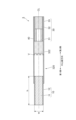
- ⁇ Second embodiment> 6A and 6B are diagrams showing an example of the configuration of the stick 2 according to the second embodiment, where (a) is a longitudinal section and (b) is a diagram showing an example of a section taken along VIb-VIb.
- a stick 2 according to the second embodiment differs from the stick 1 according to the first embodiment in a cooling section 220 corresponding to the cooling section 20 . Differences from the first embodiment will be described below.
- the same reference numerals are used for the same items in the first embodiment and the second embodiment, and detailed descriptions thereof are omitted.
- the cooling unit 220 is arranged adjacent to the base material unit 10 and the filter unit 30, and is provided in the molding paper 221 which is cylindrically molded so that the cross section is hollow (cavity). and a heat exchanger 222 .
- Forming paper 221 has openings V through which air flows from the outside to the inside.
- the heat exchanging material 222 is provided on the opposite side of the opening V from the substrate portion 10 . It can be exemplified that the forming paper 221 is the same as the forming paper 21 .
- the heat exchange material 222 is a coating layer formed on the inner wall surface of the cooling section 220. As shown in FIG. Since the heat exchange material 222 is a coating layer, it is possible to improve the permeability of the aerosol in the second side direction compared to the heat exchange material 22 .
- This coating layer can be applied to the inner wall surface of the forming paper 221 of the cooling unit 220 by attaching the sheet-like heat exchange material 222, or by applying a cooling element or fragrance as a coating material to the inner wall surface of the forming paper 221 of the cooling unit 220.
- the stick 2 includes the base portion 10 including the aerosol source 11 and the cylindrical cooling portion 220 that cools vapor generated by heating the base portion 10 to generate aerosol.
- the cooling part 220 has an opening V through which air flows into the inside from the outside, and a coating capable of exchanging heat with the aerosol on the side opposite to the base part 10 with respect to the opening V inside the cooling part 220
- a heat exchanging material 222 forming a coating layer capable of imparting fragrance to a layer or an aerosol is provided, and is not provided on the substrate portion 10 side of the opening V.
- the stick 2 is inserted into the holding portion 140 of the suction device 100 . After the temperature of the substrate portion 10 heated by the heating portion 121 reaches a predetermined temperature, the user sucks the substrate portion 10 to generate an aerosol. When the user inhales, the cooling unit 220 cools the vapor and the aerosol.
- the cooling part 220 has an opening V through which air flows into the cooling part 220 from the outside.
- the aerosol passing through the heat exchange material 222 is preferably not condensed nuclei with water molecules adsorbed on the surface in order to suppress adhesion to the inner wall surface of the cooling unit 220 and the heat exchange material 222 .
- the air flows into the cooling unit 220 from the outside at the time of suction. Cooling of steam entering from 10 can be facilitated.
- the stick 2 can improve the delivery efficiency of the aerosol during inhalation, compared to a configuration in which the aperture V is not formed.
- cooling in the cooling unit 220 means cooling to the extent that the vapor is liquefied and an aerosol is generated. Therefore, if the aerosol generated by the cooling unit 220 is sucked as it is, the temperature of the aerosol is high and the user may feel uncomfortable.
- the heat exchanging material 222 is a coating layer capable of exchanging heat with the aerosol, it absorbs heat from the aerosol, which is at a high temperature when the user inhales it, and further cools it.
- the heat exchange material 222 is provided on the side opposite to the base material portion 10 with respect to the opening V, the aerosol generated by cooling the steam generated by the heating of the base material portion 10 in the cooling portion 220 is Pass through heat exchange article 222 . This suppresses aggregation of vapor generated by heating the base member 10 and suppresses a decrease in aerosol delivery efficiency.
- the stick 2 can lower the temperature of the aerosol to a temperature more suitable for inhalation than the configuration without the heat exchange material 222 .
- the delivery amount of the substance generated by heating for example, nicotine and glycerin
- the heat exchange material 222 is reduced by the heat exchange material 222. It is possible to suppress the decrease due to the provision of.
- the heat exchange material 222 provided inside the forming paper 221 of the cooling unit 220 is preferably a coating layer covering at least a part of the inner wall surface of the forming paper 221 of the cooling unit 220 . If the heat exchanging material 222 is a folded sheet or a solid object, the permeability of the aerosol in the second lateral direction is reduced. In the present embodiment, the heat exchanging material 222 is a coating layer covering at least a partial area of the inner wall surface of the forming paper 221 of the cooling unit 220, and thus maintains the aerosol permeability in the second side direction. As a result, a decrease in aerosol delivery efficiency can be suppressed.
- the heat exchange material 222 which is a coating layer, is formed of a sheet attached to the inner wall surface of the forming paper 221 of the cooling unit 220, the heat exchange material 222 is located on the intended area of the inner wall surface of the forming paper 221. can be coated on
- the heat exchange material 222 which is a coating layer, is formed of the coating material applied to the inner wall surface of the forming paper 221 of the cooling unit 220, the heat exchange material 222 is formed on the intended area of the inner wall surface of the forming paper 221. can be easily coated on
- FIG. 7 is a view showing a longitudinal section of the stick 3 according to the third embodiment.
- the stick 3 according to the third embodiment differs from the stick 1 described above in the cooling section 320 corresponding to the cooling section 20 . Differences from the first embodiment will be described below.
- the same reference numerals are used for the same components as in the first embodiment, and detailed description thereof will be omitted.
- the cooling section 320 differs from the stick 1 in that it does not have a member corresponding to the forming paper 21 .
- the cooling part 320 is a space formed inside the stick 3, and is a cylindrical space surrounded by the second side surface of the base material part 10, the first side surface of the filter part 30, and the chipping paper 40. be.
- the cooling part 320 has an opening V through which air flows from the outside to the inside, and a heat exchanging material 322 on the opposite side of the opening V from the base material part 10 .
- the heat exchange material 322 is the same as the heat exchange material 22.
- the heat exchange article 322 may be the same as the heat exchange article 222 .
- the stick 3 includes the base portion 10 including the aerosol source 11 and the cylindrical cooling portion 320 that cools vapor generated by heating the base portion 10 to generate aerosol.
- the cooling part 320 has an opening V through which air flows into the inside from the outside, and a coating capable of exchanging heat with the aerosol on the side opposite to the base part 10 with respect to the opening V inside A heat exchanging material 322 forming a layer is provided, and is not provided on the base member 10 side of the opening V.
- the stick 3 similarly to the stick 1, it is possible to adjust the temperature or flavor of the aerosol while maintaining the delivery amount of the product.
- the cooling section 320 is a space formed between the base material section 10 and the filter section 30 by the tip paper 40 .
- the tip paper 40 makes the volume smaller than the space formed between the base material part 10 and the filter part 30 .
Abstract
A non-combustion heating-type stick 1 comprising a base material part 10 containing an aerosol source 11 and a tubular cooling part 20 for cooling vapor generated by heating the base material part 10 to generate an aerosol, wherein: the cooling part 20 has an opening V through which air flows from the outside into the interior; and, in the inside thereof, a heat exchanger 22, which is capable of exchanging heat with the aerosol or imparting an aroma to the aerosol, is formed on the opposite side of the base material part 10 with respect to the opening V but not on the side of the base material part 10 with respect to the opening V.
Description
本発明は、非燃焼加熱型スティックに関する。
The present invention relates to non-combustion heating sticks.
例えば、特許文献1に記載された非燃焼加熱喫煙物品は、たばこ含有セグメントと、紙と紙上に設けられたポリマーを含むポリマー層とを含むポリマー塗工紙を含む冷却セグメントと、を備える。
また、特許文献2に記載された非燃焼加熱喫煙物品は、たばこおよびエアロゾル生成基材を含むたばこ含有セグメントと、周上に穿孔を有する筒状の冷却セグメントと、冷却セグメントより小さい内径を有する筒状の部材と、を備える。 For example, the non-combustion heating smoking article described in US Pat. No. 6,200,400 comprises a tobacco-containing segment and a cooling segment comprising a polymer-coated paper comprising paper and a polymer layer comprising a polymer disposed on the paper.
Also, a non-combustion heated smoking article described in US Pat. and a shaped member.
エアロゾル源を含む基材を加熱することでエアロゾルを生成する吸引装置において、ユーザへ満足感の高いエアロゾルを提供するため、加熱により生成される物(例えばニコチンやグリセリン)のデリバリー量を維持しつつ、エアロゾルの温度調整又は香喫味の調整を行うことが望まれている。
本発明は、生成物のデリバリー量を維持しつつ、エアロゾルの温度調整又は香喫味の調整を行うことができる非燃焼加熱型スティックを提供することを目的とする。 In an inhalation device that generates an aerosol by heating a substrate containing an aerosol source, in order to provide an aerosol that is highly satisfying to the user, while maintaining the delivery amount of the substance (such as nicotine and glycerin) generated by heating. , it is desired to adjust the temperature or flavor of the aerosol.
An object of the present invention is to provide a non-combustion heating stick that can adjust the temperature or taste of the aerosol while maintaining the delivery amount of the product.
かかる目的のもと完成させた本発明の第1の特徴は、エアロゾル源を含む基材部と、前記基材部が加熱されることで生成された蒸気を冷却してエアロゾルを生成する筒状の冷却部と、を備え、前記冷却部は、外部から内部に空気を流入する開孔を有し、内部に、当該開孔に対して前記基材部とは反対側に前記エアロゾルとの間で熱交換可能な物又は当該エアロゾルに付香可能な物が設けられ、当該開孔よりも当該基材部側には設けられていない非燃焼加熱型スティックである。
第2の特徴は、前記冷却部の内部に設けられた物は、香料成分を含むことであっても良い。
第3の特徴は、前記香料成分は、メンソールであることであっても良い。
第4の特徴は、前記冷却部の内部に設けられた物は、ギャザー状のシートであることであっても良い。
第5の特徴は、前記冷却部の内部に設けられた物は、前記冷却部の内壁面の少なくとも一部の領域を被膜する被膜層であることであっても良い。
第6の特徴は、前記被膜層は、前記冷却部の内壁面に貼り付けられたシートにより形成されることであっても良い。
第7の特徴は、前記被膜層は、前記冷却部の内壁面に塗布された被膜材により形成されることであっても良い。
第8の特徴は、前記冷却部は、内径が前記エアロゾル源の外径と略同一であることであっても良い。
第9の特徴は、前記基材部は、エアロゾル源の周囲に巻かれた巻紙を有し、前記冷却部は、紙が巻かれることで筒状に成形されており、前記筒状に成形された紙の内径は、前記巻紙の内径と略同一であることであっても良い。
第10の特徴は、前記エアロゾルが通過するフィルタ部と、前記基材部と前記フィルタ部とを連結するチップペーパーとをさらに備え、前記冷却部は、前記チップペーパーにより、前記基材部と前記フィルタ部との間に形成された空間であることであっても良い。 The first feature of the present invention completed for this purpose is a base member including an aerosol source, and a tubular member that cools the vapor generated by heating the base member to generate an aerosol. and a cooling part, wherein the cooling part has an opening for allowing air to flow from the outside to the inside, and the aerosol is provided inside the opening on the side opposite to the base part with respect to the opening The non-combustion heating stick is provided with a substance capable of exchanging heat with the aerosol or a substance capable of imparting fragrance to the aerosol, and is not provided on the side of the base member rather than the opening.
A second feature may be that the object provided inside the cooling unit contains a fragrance component.
A third feature may be that the perfume component is menthol.
A fourth feature may be that the object provided inside the cooling unit is a gathered sheet.
A fifth feature may be that the object provided inside the cooling section is a coating layer covering at least a partial region of the inner wall surface of the cooling section.
A sixth feature may be that the coating layer is formed of a sheet attached to an inner wall surface of the cooling section.
A seventh feature may be that the coating layer is formed of a coating material applied to an inner wall surface of the cooling section.
An eighth feature may be that the inner diameter of the cooling part is substantially the same as the outer diameter of the aerosol source.
A ninth feature is that the base member has a wrapping paper wrapped around the aerosol source, the cooling unit is formed into a tubular shape by rolling the paper, and the cooling unit is formed into a tubular shape. The inner diameter of the wrapping paper may be substantially the same as the inner diameter of the wrapping paper.
A tenth feature further includes a filter portion through which the aerosol passes and tip paper connecting the base portion and the filter portion, and the cooling portion is configured to connect the base portion and the filter portion by the tip paper. It may be a space formed between the filter section.
第1の特徴によれば、生成物のデリバリー量を維持しつつ、エアロゾルの温度調整又は香喫味の調整を行うことができる。
第2の特徴によれば、香料成分を含まない構成と比較して、エアロゾルの冷却を促進しつつ、エアロゾルに香喫味を付与することができる。
第3の特徴によれば、香料成分としてメンソールを含まない構成と比較して、エアロゾルに香喫味を付与しつつ、ユーザが体感するエアロゾルの温度を下げることができる。
第4の特徴によれば、ギャザー状のシートではない構成と比較して、生成物のデリバリー量を維持しつつ、エアロゾルの冷却を促進することができる。
第5の特徴によれば、被膜層ではない構成と比較して、エアロゾルのデリバリー効率の低下を抑制することができる。
第6の特徴によれば、冷却部の内壁面の意図する領域を被膜することができる。
第7の特徴によれば、冷却部の内壁面の意図する領域を容易に被膜することができる。
第8の特徴によれば、冷却部の内径がエアロゾル源の外径と略同一ではない構成と比較して、エアロゾルのデリバリー効率の低下を抑制することができる。
第9の特徴によれば、冷却部を成形する紙の内径が基材部の巻紙の内径と略同一ではない構成と比較して、エアロゾルのデリバリー効率の低下を抑制することができる。
第10の特徴によれば、チップペーパーの内側に冷却部を成形する部材を備える構成と比較して、エアロゾルのデリバリー効率の低下を抑制することができる。 According to the first feature, it is possible to adjust the temperature or flavor of the aerosol while maintaining the delivery amount of the product.
According to the second feature, it is possible to impart flavor and taste to the aerosol while promoting cooling of the aerosol, as compared with a configuration that does not contain a flavor component.
According to the third feature, the temperature of the aerosol experienced by the user can be lowered while imparting a flavor to the aerosol, compared to a configuration that does not contain menthol as a fragrance component.
According to the fourth feature, cooling of the aerosol can be facilitated while maintaining product delivery compared to non-gathered sheet configurations.
According to the fifth feature, it is possible to suppress a decrease in aerosol delivery efficiency compared to a configuration that is not a coating layer.
According to the sixth feature, the intended area of the inner wall surface of the cooling section can be coated.
According to the seventh feature, the intended area of the inner wall surface of the cooling section can be easily coated.
According to the eighth feature, it is possible to suppress a decrease in aerosol delivery efficiency compared to a configuration in which the inner diameter of the cooling section is not substantially the same as the outer diameter of the aerosol source.
According to the ninth feature, it is possible to suppress a decrease in aerosol delivery efficiency compared to a configuration in which the inner diameter of the paper forming the cooling portion is not substantially the same as the inner diameter of the wrapping paper of the base portion.
According to the tenth feature, it is possible to suppress a decrease in aerosol delivery efficiency compared to a configuration in which a member forming a cooling portion is provided inside the tipping paper.
以下、添付図面を参照して、本発明に係る実施の形態について詳細に説明する。各図面には、同一の部分に同一の符号を付して示す。
Hereinafter, embodiments according to the present invention will be described in detail with reference to the accompanying drawings. In each drawing, the same parts are indicated by the same reference numerals.
<第1実施形態>
図1は、第1実施形態に係るスティックの構成の一例を示す図であり、(a)は縦断面、(b)はIb-Ib部の断面の一例を示す図である。図2は、第1実施形態に係る吸引装置100の構成例を模式的に示す模式図である。
第1実施形態に係る非燃焼加熱型スティック(以下、「スティック」と称する場合がある。)1は、基材部10と冷却部20とフィルタ部30とを備える。基材部10は、円柱状に形成されている。以下、基材部10の中心線CLの方向を、「中心線方向」と称する場合がある。スティック1は、中心線方向に、基材部10、冷却部20、フィルタ部30の順に並べた状態で巻かれることで、これらを一体化する、チップペーパー40をさらに備える。以下、中心線方向の一方の端部側(図1においては左側)を第1側、中心線方向の他方の端部側(図1においては右側)を第2側と称する場合がある。第1側は吸引装置100に挿入される方の端部側である。第2側は第1側と反対側であり、ユーザが吸引のために口で咥える端部側である。また、中心線方向に沿った断面を「縦断面」と称し、中心線方向に直交する面にて切断した断面を「横断面」と定義する。 <First embodiment>
FIG. 1 is a view showing an example of the configuration of the stick according to the first embodiment, where (a) is a longitudinal section and (b) is a view showing an example of a section taken along line Ib-Ib. FIG. 2 is a schematic diagram schematically showing a configuration example of thesuction device 100 according to the first embodiment.
A non-combustion heating stick (hereinafter sometimes referred to as “stick”) 1 according to the first embodiment includes abase portion 10 , a cooling portion 20 and a filter portion 30 . The base material portion 10 is formed in a cylindrical shape. Hereinafter, the direction of the centerline CL of the base member 10 may be referred to as the "centerline direction". The stick 1 further includes a tipping paper 40 that integrates the base material portion 10, the cooling portion 20, and the filter portion 30 by winding them in order in the direction of the center line. Hereinafter, one end side in the centerline direction (left side in FIG. 1) may be referred to as a first side, and the other end side in the centerline direction (right side in FIG. 1) may be referred to as a second side. The first side is the end side that is inserted into the suction device 100 . The second side is opposite to the first side and is the end side that the user holds in his/her mouth for suction. A cross section along the centerline direction is called a "longitudinal cross section", and a cross section taken along a plane perpendicular to the centerline direction is defined as a "transverse cross section".
図1は、第1実施形態に係るスティックの構成の一例を示す図であり、(a)は縦断面、(b)はIb-Ib部の断面の一例を示す図である。図2は、第1実施形態に係る吸引装置100の構成例を模式的に示す模式図である。
第1実施形態に係る非燃焼加熱型スティック(以下、「スティック」と称する場合がある。)1は、基材部10と冷却部20とフィルタ部30とを備える。基材部10は、円柱状に形成されている。以下、基材部10の中心線CLの方向を、「中心線方向」と称する場合がある。スティック1は、中心線方向に、基材部10、冷却部20、フィルタ部30の順に並べた状態で巻かれることで、これらを一体化する、チップペーパー40をさらに備える。以下、中心線方向の一方の端部側(図1においては左側)を第1側、中心線方向の他方の端部側(図1においては右側)を第2側と称する場合がある。第1側は吸引装置100に挿入される方の端部側である。第2側は第1側と反対側であり、ユーザが吸引のために口で咥える端部側である。また、中心線方向に沿った断面を「縦断面」と称し、中心線方向に直交する面にて切断した断面を「横断面」と定義する。 <First embodiment>
FIG. 1 is a view showing an example of the configuration of the stick according to the first embodiment, where (a) is a longitudinal section and (b) is a view showing an example of a section taken along line Ib-Ib. FIG. 2 is a schematic diagram schematically showing a configuration example of the
A non-combustion heating stick (hereinafter sometimes referred to as “stick”) 1 according to the first embodiment includes a
[スティック1の使用形態]
第1実施形態に係るスティック1は、非燃焼加熱式の吸引装置100にて使用される。図2に示すように、吸引装置100は、電力を蓄積するとともに、吸引装置100の各構成要素に電力を供給する電源部111と、吸引装置100に関する各種情報を検出するセンサ部112と、情報をユーザに通知する通知部113とを備えている。また、吸引装置100は、吸引装置100の動作のための各種情報を記憶する記憶部114と、吸引装置100と他の装置との間で情報を送受信するための通信部115と、吸引装置100内の動作全般を制御する制御部116とを備えている。また、吸引装置100は、スティック1を加熱する加熱部121と、スティック1を保持する保持部140と、内部空間141を外部に連通する開口142と、加熱部121から吸引装置100の他の構成要素への伝熱を防止する断熱部144とを備えている。吸引装置100においては、保持部140にスティック1が保持された状態で、ユーザによる吸引が行われる。 [Usage pattern of stick 1]
Thestick 1 according to the first embodiment is used in a non-combustion heating suction device 100 . As shown in FIG. 2, the suction device 100 includes a power supply unit 111 that accumulates power and supplies power to each component of the suction device 100, a sensor unit 112 that detects various information about the suction device 100, an information and a notification unit 113 for notifying the user of. The suction device 100 also includes a storage unit 114 for storing various information for the operation of the suction device 100, a communication unit 115 for transmitting and receiving information between the suction device 100 and other devices, and the suction device 100. and a control unit 116 for controlling overall internal operations. The suction device 100 also includes a heating unit 121 that heats the stick 1, a holding unit 140 that holds the stick 1, an opening 142 that communicates the internal space 141 with the outside, and other components of the suction device 100 from the heating unit 121. and a heat insulator 144 that prevents heat transfer to the element. In the suction device 100 , the user performs suction while the stick 1 is held by the holding portion 140 .
第1実施形態に係るスティック1は、非燃焼加熱式の吸引装置100にて使用される。図2に示すように、吸引装置100は、電力を蓄積するとともに、吸引装置100の各構成要素に電力を供給する電源部111と、吸引装置100に関する各種情報を検出するセンサ部112と、情報をユーザに通知する通知部113とを備えている。また、吸引装置100は、吸引装置100の動作のための各種情報を記憶する記憶部114と、吸引装置100と他の装置との間で情報を送受信するための通信部115と、吸引装置100内の動作全般を制御する制御部116とを備えている。また、吸引装置100は、スティック1を加熱する加熱部121と、スティック1を保持する保持部140と、内部空間141を外部に連通する開口142と、加熱部121から吸引装置100の他の構成要素への伝熱を防止する断熱部144とを備えている。吸引装置100においては、保持部140にスティック1が保持された状態で、ユーザによる吸引が行われる。 [Usage pattern of stick 1]
The
加熱部121は、スティック1の基材部10を加熱する。加熱部121は、金属又はポリイミド等の任意の素材で構成される。例えば、加熱部121は、フィルム状に構成され、保持部140の外周を覆うように配置される。そして、加熱部121が発熱すると、スティック1に含まれるエアロゾル源11がスティック1の外周から加熱される。加熱部121は、電源部111から給電されると発熱する。一例として、所定のユーザ入力が行われたことがセンサ部112により検出された場合に、給電されてもよい。加熱部121により加熱されたスティック1の温度が所定の温度に達した場合に、ユーザによる吸引が可能となる。その後、所定のユーザ入力が行われたことがセンサ部112により検出された場合に、給電が停止されてもよい。他の一例として、ユーザによる吸引が行われたことがセンサ部112により検出されている期間において、給電され、エアロゾルが生成されてもよい。
The heating part 121 heats the base material part 10 of the stick 1 . The heating part 121 is made of any material such as metal or polyimide. For example, the heating part 121 is configured in a film shape and arranged so as to cover the outer periphery of the holding part 140 . Then, when the heating part 121 generates heat, the aerosol source 11 included in the stick 1 is heated from the outer circumference of the stick 1 . The heating unit 121 generates heat when supplied with power from the power supply unit 111 . As an example, power may be supplied when the sensor unit 112 detects that a predetermined user input has been performed. When the temperature of the stick 1 heated by the heating unit 121 reaches a predetermined temperature, the user can suck. After that, when the sensor unit 112 detects that a predetermined user input has been performed, the power supply may be stopped. As another example, power may be supplied and aerosol may be generated during a period in which the sensor unit 112 detects that the user has inhaled.
断熱部144は、少なくとも加熱部121の外周を覆うように配置される。例えば、断熱部144は、真空断熱材、及びエアロゲル断熱材等により構成される。なお、真空断熱材とは、例えば、グラスウール及びシリカ(ケイ素の粉体)等を樹脂製のフィルムで包んで高真空状態にすることで、気体による熱伝導を限りなくゼロに近づけた断熱材である。
The heat insulation part 144 is arranged so as to cover at least the outer periphery of the heating part 121 . For example, the heat insulating part 144 is made of a vacuum heat insulating material, an airgel heat insulating material, or the like. A vacuum insulation material is, for example, a heat insulation material in which heat conduction due to gas is nearly zero by wrapping glass wool and silica (powder of silicon) in a resin film to create a high vacuum state. be.
[基材部10]
基材部10は、加熱されることでエアロゾルが生成される蒸気を生じるエアロゾル源11と、エアロゾル源11の外周を覆う巻紙12とを有している。基材部10は、エアロゾル源11が巻紙12に巻かれることで円柱状に形成されている。エアロゾル源11は、例えば、たばこ刻み又はたばこ原料を、粒状、シート状、又は粉末状に成形した加工物などの、たばこ由来のものであってもよい。また、エアロゾル源11は、たばこ以外の植物(例えばミント及びハーブ等)から作られた、非たばこ由来のものを含んでいてもよい。一例として、エアロゾル源11は、香料を含んでいてもよい。香料の種類は、特に限定されず、良好な香味を付与する観点から、特に好ましくはメンソールである。また、これらの香料は1種を単独で用いても、又は2種以上を併用してもよい。吸引装置100が医療用吸入器である場合、エアロゾル源11は、患者が吸入するための薬剤を含んでもよい。なお、エアロゾル源11は固体に限られるものではなく、例えば、グリセリン及びプロピレングリコール等の多価アルコール、並びに水等の液体であってもよい。基材部10の少なくとも一部は、スティック1が保持部140に保持された状態において、保持部140の内部空間141に収容される。 [Base material portion 10]
Thebase member 10 has an aerosol source 11 that generates vapor from which an aerosol is generated when heated, and a wrapping paper 12 that covers the outer periphery of the aerosol source 11 . The base material part 10 is formed in a cylindrical shape by winding the aerosol source 11 around the wrapping paper 12 . The aerosol source 11 may be tobacco-derived, such as, for example, tobacco cuts or tobacco raw materials molded into granules, sheets, or powder. The aerosol source 11 may also include non-tobacco sources made from plants other than tobacco, such as mints and herbs. As an example, the aerosol source 11 may contain perfume. The type of fragrance is not particularly limited, and menthol is particularly preferable from the viewpoint of imparting a good flavor. Moreover, these fragrance|flavors may be used individually by 1 type, or may use 2 or more types together. If the inhalation device 100 is a medical inhaler, the aerosol source 11 may contain a medicament for inhalation by the patient. The aerosol source 11 is not limited to solids, and may be polyhydric alcohols such as glycerin and propylene glycol, and liquids such as water. At least part of the base material portion 10 is housed in the internal space 141 of the holding portion 140 while the stick 1 is held by the holding portion 140 .
基材部10は、加熱されることでエアロゾルが生成される蒸気を生じるエアロゾル源11と、エアロゾル源11の外周を覆う巻紙12とを有している。基材部10は、エアロゾル源11が巻紙12に巻かれることで円柱状に形成されている。エアロゾル源11は、例えば、たばこ刻み又はたばこ原料を、粒状、シート状、又は粉末状に成形した加工物などの、たばこ由来のものであってもよい。また、エアロゾル源11は、たばこ以外の植物(例えばミント及びハーブ等)から作られた、非たばこ由来のものを含んでいてもよい。一例として、エアロゾル源11は、香料を含んでいてもよい。香料の種類は、特に限定されず、良好な香味を付与する観点から、特に好ましくはメンソールである。また、これらの香料は1種を単独で用いても、又は2種以上を併用してもよい。吸引装置100が医療用吸入器である場合、エアロゾル源11は、患者が吸入するための薬剤を含んでもよい。なお、エアロゾル源11は固体に限られるものではなく、例えば、グリセリン及びプロピレングリコール等の多価アルコール、並びに水等の液体であってもよい。基材部10の少なくとも一部は、スティック1が保持部140に保持された状態において、保持部140の内部空間141に収容される。 [Base material portion 10]
The
エアロゾル源11を巻紙12で巻いてなる基材部10は、数式1に定義されるアスペクト比が1以上である形状を満たす円柱状を有していることが好ましい。
The base material portion 10 formed by winding the aerosol source 11 with the wrapping paper 12 preferably has a cylindrical shape that satisfies a shape with an aspect ratio defined by Equation 1 of 1 or more.
wは基材部10における横断面の幅、hは基材部10の中心線方向の大きさであり、h≧wであることが好ましい。横断面の形状は限定されず、多角、角丸多角、円、楕円等であって良く、幅wは横断面が円形の場合は直径、楕円形である場合は長径、多角形又は角丸多角である場合は外接円の直径又は外接楕円の長径である。基材部10を構成するエアロゾル源11における横断面の幅は4mm以上9mm以下であることが好ましい。
w is the width of the cross section of the base member 10, h is the size of the base member 10 in the direction of the center line, and h≧w is preferred. The shape of the cross section is not limited, and may be a polygon, a polygon with rounded corners, a circle, an ellipse, or the like. is the diameter of the circumscribed circle or the major axis of the circumscribed ellipse. It is preferable that the width of the cross section of the aerosol source 11 constituting the base material portion 10 is 4 mm or more and 9 mm or less.
基材部10の中心線方向の大きさhは、製品のサイズに合わせて適宜変更し得るが、通常10mm以上であり、12mm以上であることが好ましく、15mm以上であることがより好ましく、18mm以上であることがさらに好ましい。また、基材部10の中心線方向の大きさhは、通常70mm以下であり、50mm以下であることが好ましく、30mm以下であることがより好ましく、25mm以下であることがさらに好ましい。
また、中心線方向において、スティック1の大きさに対する基材部10の大きさhの割合は、特段制限されないが、デリバリー量とエアロゾル温度のバランスの観点から、通常10%以上であり、20%以上であることが好ましく、25%以上であることがより好ましく、30%以上であることがさらに好ましい。また、スティック1の大きさに対する基材部10の大きさhの割合は、通常80%以下であり、70%以下であることが好ましく、60%以下であることがより好ましく、50%以下であることがさらに好ましく、45%以下であることが特に好ましく、40%以下であることが最も好ましい。 The size h of thebase material portion 10 in the center line direction can be appropriately changed according to the size of the product. It is more preferable that it is above. The size h of the base material portion 10 in the center line direction is usually 70 mm or less, preferably 50 mm or less, more preferably 30 mm or less, and even more preferably 25 mm or less.
In addition, in the center line direction, the ratio of the size h of thebase material part 10 to the size of the stick 1 is not particularly limited, but from the viewpoint of the balance between the delivery amount and the aerosol temperature, it is usually 10% or more, and 20%. It is preferably 25% or more, more preferably 30% or more. In addition, the ratio of the size h of the base material portion 10 to the size of the stick 1 is usually 80% or less, preferably 70% or less, more preferably 60% or less, and 50% or less. 45% or less is particularly preferable, and 40% or less is most preferable.
また、中心線方向において、スティック1の大きさに対する基材部10の大きさhの割合は、特段制限されないが、デリバリー量とエアロゾル温度のバランスの観点から、通常10%以上であり、20%以上であることが好ましく、25%以上であることがより好ましく、30%以上であることがさらに好ましい。また、スティック1の大きさに対する基材部10の大きさhの割合は、通常80%以下であり、70%以下であることが好ましく、60%以下であることがより好ましく、50%以下であることがさらに好ましく、45%以下であることが特に好ましく、40%以下であることが最も好ましい。 The size h of the
In addition, in the center line direction, the ratio of the size h of the
基材部10中のエアロゾル源11の含有量は、特段制限されないが、200mg以上800mg以下を挙げることができ、250mg以上600mg以下が好ましい。この範囲は、特に、円周22mm、中心線方向の大きさ20mmの基材部10において好適である。
The content of the aerosol source 11 in the base material portion 10 is not particularly limited, but may be 200 mg or more and 800 mg or less, preferably 250 mg or more and 600 mg or less. This range is particularly suitable for the base member 10 with a circumference of 22 mm and a size of 20 mm in the centerline direction.
ここで、たばこ刻みを含むエアロゾル源11を説明する。エアロゾル源11に含まれるたばこ刻みの材料は特に限定されず、ラミナや中骨等の公知のものを用いることができる。また、乾燥したたばこ葉を平均粒径が20μm以上200μm以下になるように粉砕してたばこ粉砕物とし、これを均一化したものをシート加工したもの(以下、単に均一化シートともいう)を刻んだものであってもよい。さらに、基材部10の中心線方向の大きさと同程度の大きさを有する均一化シートを、基材部10の中心線方向と略水平に刻んだものをエアロゾル源11に充填する、いわゆるストランドタイプであってもよい。
また、たばこ刻みの幅は、エアロゾル源11に充填するうえで0.5mm以上2.0mm以下であることが好ましい。 Anaerosol source 11 containing tobacco cuts will now be described. The cut tobacco material contained in the aerosol source 11 is not particularly limited, and known materials such as lamina and backbone can be used. Alternatively, dried tobacco leaves are pulverized to an average particle size of 20 μm or more and 200 μm or less to obtain pulverized tobacco, which is homogenized and processed into a sheet (hereinafter simply referred to as a homogenized sheet). It can be anything. Furthermore, a homogenizing sheet having a size approximately equal to the size in the center line direction of the base material part 10 is chopped substantially horizontally with the center line direction of the base material part 10, and the aerosol source 11 is filled with the so-called strand. can be a type.
Moreover, the width of the chopped tobacco is preferably 0.5 mm or more and 2.0 mm or less for filling theaerosol source 11 .
また、たばこ刻みの幅は、エアロゾル源11に充填するうえで0.5mm以上2.0mm以下であることが好ましい。 An
Moreover, the width of the chopped tobacco is preferably 0.5 mm or more and 2.0 mm or less for filling the
たばこ刻み及び均一化シートの作製に用いるたばこ葉について、使用するたばこの種類は、様々なものを用いることができる。例えば、黄色種、バーレー種、オリエント種、在来種、その他のニコチアナ-タバカム系品種、ニコチアナ-ルスチカ系品種、及びこれらの混合物を挙げることができる。混合物については、目的とする味となるように、各品種を適宜ブレンドして用いることができる。たばこの品種の詳細は、「たばこの事典、たばこ総合研究センター、2009.3.31」に開示されている。均一化シートの製造方法、すなわち、たばこ葉を粉砕して均一化シートに加工する方法は従来の方法が複数存在している。1つ目は抄紙プロセスを用いて抄造シートを作製する方法である。2つ目は水等の適切な溶媒を、粉砕したたばこ葉に混ぜて均一化した後に金属製板もしくは金属製板ベルトの上に均一化物を薄くキャスティングし、乾燥させてキャストシートを作製する方法である。3つ目は水等の適切な溶媒を、粉砕したたばこ葉に混ぜて均一化したものをシート状に押し出し成型して圧延シートを作製する方法である。均一化シートの種類については、「たばこの事典、たばこ総合研究センター、2009.3.31」に詳細が開示されている。
Various kinds of tobacco can be used for the tobacco leaves used for producing the cut tobacco and the homogenized sheet. Examples include yellow, burley, oriental, landrace, other Nicotiana-tabacum varieties, Nicotiana-Rustica varieties, and mixtures thereof. As for the mixture, each kind can be appropriately blended and used so as to obtain the desired taste. Details of tobacco varieties are disclosed in "Tobacco Encyclopedia, Tobacco Research Center, March 31, 2009". There are a number of conventional methods for producing homogenized sheets, that is, methods for pulverizing tobacco leaves and processing them into homogenized sheets. The first is a method of producing a papermaking sheet using a papermaking process. The second method is to mix pulverized tobacco leaves with an appropriate solvent such as water to homogenize the mixture, and then thinly cast the homogenized product on a metal plate or metal plate belt and dry it to produce a cast sheet. is. A third method is to prepare a rolled sheet by mixing a suitable solvent such as water with pulverized tobacco leaves, homogenizing the mixture, and extruding the mixture into a sheet. Details of the types of homogenizing sheets are disclosed in "Encyclopedia of Tobacco, Tobacco Research Center, March 31, 2009".
エアロゾル源11の水分含有量は、エアロゾル源11の全量に対して10質量%以上15質量%以下を挙げることができ、11質量%以上13質量%以下であることが好ましい。このような水分含有量であると、巻染みの発生を抑制し、基材部10の製造時の巻上適性を良好にする。
The water content of the aerosol source 11 can be 10% by mass or more and 15% by mass or less, preferably 11% by mass or more and 13% by mass or less, relative to the total amount of the aerosol source 11 . Such a water content suppresses the occurrence of winding stains, and improves the winding suitability of the base material portion 10 during manufacturing.
エアロゾル源11は、特に限定されず、用途に応じて種々の天然物からの抽出物質及び/又はそれらの構成成分を含んでいてもよい。抽出物質及び/又はそれらの構成成分として、グリセリン、プロピレングリコール、トリアセチン、1,3-ブタンジオール、及びこれらの混合物を挙げることができる。
エアロゾル源11中の抽出物質及び/又はそれらの構成成分の含有量は、特に限定されず、十分にエアロゾルを生成させるとともに、良好な香味を付与する観点から、エアロゾル源11の全量に対して通常5質量%以上であり、好ましくは10質量%以上である。また、エアロゾル源11中の抽出物質及び/又はそれらの構成成分の含有量は、通常50質量%以下であり、好ましくは15質量%以上、25質量%以下である。 Theaerosol source 11 is not particularly limited, and may contain extracts from various natural products and/or constituents thereof, depending on the application. Extractable substances and/or constituents thereof may include glycerin, propylene glycol, triacetin, 1,3-butanediol, and mixtures thereof.
The content of the extracting substance and/or its constituent components in theaerosol source 11 is not particularly limited, and from the viewpoint of sufficiently generating an aerosol and imparting a good flavor, it is usually It is 5% by mass or more, preferably 10% by mass or more. In addition, the content of the extractable substance and/or its constituent components in the aerosol source 11 is usually 50% by mass or less, preferably 15% by mass or more and 25% by mass or less.
エアロゾル源11中の抽出物質及び/又はそれらの構成成分の含有量は、特に限定されず、十分にエアロゾルを生成させるとともに、良好な香味を付与する観点から、エアロゾル源11の全量に対して通常5質量%以上であり、好ましくは10質量%以上である。また、エアロゾル源11中の抽出物質及び/又はそれらの構成成分の含有量は、通常50質量%以下であり、好ましくは15質量%以上、25質量%以下である。 The
The content of the extracting substance and/or its constituent components in the
エアロゾル源11における充填密度は、特に限定されないが、スティック1の性能を担保し、良好な香味を付与する観点から、通常250mg/cm3以上であり、好ましくは300mg/cm3以上である。また、エアロゾル源11における充填密度は、通常400mg/cm3以下であり、好ましくは350mg/cm3以下である。
The packing density of the aerosol source 11 is not particularly limited, but is usually 250 mg/cm 3 or more, preferably 300 mg/cm 3 or more, from the viewpoint of securing the performance of the stick 1 and imparting a good flavor. Also, the packing density in the aerosol source 11 is usually 400 mg/cm 3 or less, preferably 350 mg/cm 3 or less.
また、エアロゾル源11は、たばこシートから構成されてもよい。たばこシートの枚数は、1枚であってもよく、2枚以上であってもよい。
Also, the aerosol source 11 may be composed of a tobacco sheet. The number of tobacco sheets may be one, or two or more.
エアロゾル源11が、1枚のたばこシートから構成される場合の態様としては、例えば、その一辺が、被充填物の中心線方向の大きさと同程度の大きさを有するたばこシートが、被充填物の中心線方向と水平に複数回折り返された状態で充填態様(いわゆるギャザーシート)が挙げられる。また、その一辺が、被充填物の中心線方向の大きさと同程度の大きさを有するたばこシートを、被充填物の中心線方向と直交する方向に巻き回された状態で充填される態様も挙げられる。
In the case where the aerosol source 11 is composed of one tobacco sheet, for example, a tobacco sheet having one side of a size approximately equal to the size in the center line direction of the object to be filled is used as the object to be filled. A filling mode (so-called gathered sheet) is exemplified in a state in which the sheet is folded back multiple times horizontally with respect to the center line direction of the sheet. In addition, there is also a mode in which a tobacco sheet having one side of which is approximately the same size as the centerline direction of the object to be filled is wound in a direction orthogonal to the centerline direction of the object to be filled. mentioned.
エアロゾル源11が、2枚以上のたばこシートから構成される場合の態様としては、例えば、その1辺が、被充填物の中心線方向の大きさと同程度の大きさ有する複数のたばこシートが、同心状に配置されるように、被充填物の中心線方向と直交する方向に巻き回された状態で充填される態様が挙げられる。「同心状に配置される」とは、すべてのたばこシートの中心が略同じ位置にあるように配置されていることをいう。
As a mode in which the aerosol source 11 is composed of two or more tobacco sheets, for example, a plurality of tobacco sheets each having a size approximately equal to the size in the center line direction of the object to be filled, A mode in which the material is wound in a direction orthogonal to the center line direction of the material to be filled so as to be arranged concentrically is exemplified. "Concentrically arranged" means that the centers of all the tobacco sheets are arranged at approximately the same position.
2枚以上のたばこシートはすべて同じ組成あるいは物性であってもよいし、各たばこシートの中の一部又は全部が異なる組成あるいは物性であってもよい。また、各たばこシートの厚みは、それぞれが同一であってもよく、異なっていてもよい。
各たばこシートの厚みについては制限されないが、伝熱効率と強度の兼ね合いから、150μm以上1000μm以下が好ましく、200μm以上600μm以下がより好ましい。 Two or more tobacco sheets may all have the same composition or physical properties, or a part or all of each tobacco sheet may have different compositions or physical properties. Moreover, the thickness of each tobacco sheet may be the same or different.
The thickness of each tobacco sheet is not limited, but is preferably 150 μm or more and 1000 μm or less, more preferably 200 μm or more and 600 μm or less, in terms of balance between heat transfer efficiency and strength.
エアロゾル源11は、幅の異なる複数のたばこシートを準備して、第1側から第2側に向かって幅が小さくなるように積層した積層体を調製し、これを巻管に通して巻き上げ成形することで製造できる。
この製造方法によれば、複数のたばこシートが、中心線方向に延在するとともに、CLを中心として同心状に配置されるようになる。 Theaerosol source 11 prepares a plurality of tobacco sheets having different widths, prepares a laminated body in which the width decreases from the first side to the second side, passes the laminated body through a winding tube, and winds and forms the laminated body. It can be manufactured by
According to this manufacturing method, the plurality of tobacco sheets extend in the centerline direction and are arranged concentrically around CL.
この製造方法によれば、複数のたばこシートが、中心線方向に延在するとともに、CLを中心として同心状に配置されるようになる。 The
According to this manufacturing method, the plurality of tobacco sheets extend in the centerline direction and are arranged concentrically around CL.
この製造方法において、積層体は巻上げ成形後に隣接するたばこシート間に非接触部が形成されるように調製されることが好ましい。複数のたばこシート間に、たばこシートが接触しない非接触部(隙間)が存在すると、香味流路を確保して香味成分のデリバリー効率を高めることができる。他方で、複数のたばこシートの接触部分を介してヒーターからの熱を外側のたばこシートに伝達できるので高い伝熱効率を確保することができる。
複数のたばこシート間に、たばこシートが接触しない非接触部を設けるために、例えば、エンボス加工したたばこシートを用いる、隣接するたばこシート同士の全面を接着せずに積層する、隣接するたばこシート同士の一部を接着して積層する、あるいは隣接するたばこシート同士の全面あるいは一部を、巻上げ成形後に剥がれるように軽度に接着して積層することで積層体を調製する方法を挙げることができる。
巻紙12を含めた基材部10を調製する場合には、積層体の第1側の端面に巻紙12を配置してもよい。 In this manufacturing method, the laminate is preferably prepared so that a non-contact portion is formed between adjacent tobacco sheets after roll-forming. If there is a non-contact portion (gap) between the plurality of tobacco sheets, which is not in contact with the tobacco sheets, the flavor flow path can be secured and the delivery efficiency of the flavor component can be enhanced. On the other hand, since the heat from the heater can be transferred to the outer tobacco sheets through the contact portions of the plurality of tobacco sheets, high heat transfer efficiency can be ensured.
In order to provide a non-contact portion between a plurality of tobacco sheets where the tobacco sheets do not contact, for example, an embossed tobacco sheet is used, adjacent tobacco sheets are laminated without bonding the entire surfaces of adjacent tobacco sheets, and adjacent tobacco sheets are stacked together. Alternatively, the entire or part of the adjacent tobacco sheets are lightly adhered so that they can be separated after roll-forming, thereby preparing a laminate.
When thebase material portion 10 including the wrapping paper 12 is prepared, the wrapping paper 12 may be arranged on the end surface of the first side of the laminate.
複数のたばこシート間に、たばこシートが接触しない非接触部を設けるために、例えば、エンボス加工したたばこシートを用いる、隣接するたばこシート同士の全面を接着せずに積層する、隣接するたばこシート同士の一部を接着して積層する、あるいは隣接するたばこシート同士の全面あるいは一部を、巻上げ成形後に剥がれるように軽度に接着して積層することで積層体を調製する方法を挙げることができる。
巻紙12を含めた基材部10を調製する場合には、積層体の第1側の端面に巻紙12を配置してもよい。 In this manufacturing method, the laminate is preferably prepared so that a non-contact portion is formed between adjacent tobacco sheets after roll-forming. If there is a non-contact portion (gap) between the plurality of tobacco sheets, which is not in contact with the tobacco sheets, the flavor flow path can be secured and the delivery efficiency of the flavor component can be enhanced. On the other hand, since the heat from the heater can be transferred to the outer tobacco sheets through the contact portions of the plurality of tobacco sheets, high heat transfer efficiency can be ensured.
In order to provide a non-contact portion between a plurality of tobacco sheets where the tobacco sheets do not contact, for example, an embossed tobacco sheet is used, adjacent tobacco sheets are laminated without bonding the entire surfaces of adjacent tobacco sheets, and adjacent tobacco sheets are stacked together. Alternatively, the entire or part of the adjacent tobacco sheets are lightly adhered so that they can be separated after roll-forming, thereby preparing a laminate.
When the
エアロゾル源11の充填密度は、特に限定されないが、スティック1の性能を担保し、良好な香味を付与する観点から、通常250mg/cm3以上であり、好ましくは300mg/cm3以上である。また、エアロゾル源11の充填密度は、通常400mg/cm3以下であり、好ましくは350mg/cm3以下である。
The packing density of the aerosol source 11 is not particularly limited, but is usually 250 mg/cm 3 or more, preferably 300 mg/cm 3 or more, from the viewpoint of securing the performance of the stick 1 and imparting a good flavor. Also, the packing density of the aerosol source 11 is usually 400 mg/cm 3 or less, preferably 350 mg/cm 3 or less.
たばこシートには、グリセリン、プロピレングリコール、1,3-ブタンジオール等のポリオール等を添加してもよい。たばこシートへの添加量は、たばこシートの乾燥質量に対して5質量%以上50質量%以下が好ましく、15質量%以上25質量%以下がより好ましい。
Polyols such as glycerin, propylene glycol, and 1,3-butanediol may be added to tobacco sheets. The amount added to the tobacco sheet is preferably 5% by mass or more and 50% by mass or less, more preferably 15% by mass or more and 25% by mass or less, relative to the dry mass of the tobacco sheet.
たばこシートは、抄造、スラリー、圧延、等の公知の方法で適宜製造できる。なお、上述した均一化シートを用いることもできる。
抄造の場合は、以下の工程を含む方法で製造できる。1)乾燥たばこ葉を粗砕し、水で抽出して水抽出物と残渣に分離する。2)水抽出物を減圧乾燥して濃縮する。3)残渣にパルプを加え、リファイナで繊維化した後、抄紙する。4)抄紙したシートに水抽出物の濃縮液を添加して乾燥し、たばこシートとする。この場合、ニトロソアミン等の一部の成分を除去する工程を加えてもよい(特表2004-510422号公報参照)。
スラリー法の場合は、以下の工程を含む方法で製造できる。1)水、パルプ及びバインダーと、砕いたたばこ葉を混合する。2)混合物を薄く延ばして(キャストして)乾燥する。この場合、水、パルプ及びバインダーと、砕いたたばこ葉を混合したスラリーに対して紫外線照射もしくはX線照射することでニトロソアミン等の一部の成分を除去する工程を加えてもよい。 Tobacco sheets can be appropriately manufactured by known methods such as paper making, slurrying, and rolling. Note that the uniformizing sheet described above can also be used.
In the case of papermaking, it can be manufactured by a method including the following steps. 1) Dry tobacco leaves are crushed and extracted with water to separate the water extract and residue. 2) Dry and concentrate the water extract under reduced pressure. 3) Pulp is added to the residue, fiberized with a refiner, and then paper is made. 4) A concentrated solution of the water extract is added to the paper sheet and dried to obtain a tobacco sheet. In this case, a step of removing some components such as nitrosamines may be added (see JP-T-2004-510422).
In the case of the slurry method, it can be produced by a method including the following steps. 1) Mix crushed tobacco leaves with water, pulp and binder. 2) The mixture is spread (cast) and dried. In this case, a step of removing some components such as nitrosamines by irradiating a slurry obtained by mixing water, pulp and binder with crushed tobacco leaves with ultraviolet rays or X-rays may be added.
この他、国際公開第2014/104078号に記載されているように、以下の工程を含む方法によって製造された不織布状のたばこシートを用いることもできる。1)粉粒状のたばこ葉と結合剤を混合する。2)混合物を不織布によって挟む。3)積層物を熱溶着によって一定形状に成形し、不織布状のたばこシートを得る。
前記の各方法で用いる原料のたばこ葉の種類は、たばこ刻みを含むエアロゾル源11で説明したものと同じものを用いることができる。
たばこシートの組成は特に限定されないが、例えば、たばこ原料(たばこ葉)の含有量はたばこシート全質量に対して50質量%以上95質量%以下であることが好ましい。また、たばこシートはバインダーを含んでもよく、係るバインダーとしては、例えば、グアーガム、キサンタンガム、カルボキシメチルセルロース、カルボキシメチルセルロースのナトリウム塩等が挙げられる。バインダー量としては、たばこシート全質量に対して1質量%以上、10質量%以下であることが好ましい。たばこシートはさらに他の添加物を含んでもよい。添加物としては、例えばパルプなどのフィラーを挙げることができる。 In addition, as described in WO 2014/104078, a non-woven tobacco sheet manufactured by a method including the following steps can also be used. 1) Mix powdered tobacco leaves and a binder. 2) The mixture is sandwiched between non-woven fabrics. 3) Forming the laminate into a certain shape by heat welding to obtain a non-woven tobacco sheet.
The types of raw material tobacco leaves used in each of the above methods may be the same as those described for theaerosol source 11 containing cut tobacco.
Although the composition of the tobacco sheet is not particularly limited, for example, the content of the tobacco raw materials (tobacco leaves) is preferably 50% by mass or more and 95% by mass or less with respect to the total mass of the tobacco sheet. The tobacco sheet may also contain a binder, and examples of such binders include guar gum, xanthan gum, carboxymethylcellulose, sodium salts of carboxymethylcellulose, and the like. The amount of the binder is preferably 1% by mass or more and 10% by mass or less with respect to the total mass of the tobacco sheet. The tobacco sheet may further contain other additives. Examples of additives include fillers such as pulp.
前記の各方法で用いる原料のたばこ葉の種類は、たばこ刻みを含むエアロゾル源11で説明したものと同じものを用いることができる。
たばこシートの組成は特に限定されないが、例えば、たばこ原料(たばこ葉)の含有量はたばこシート全質量に対して50質量%以上95質量%以下であることが好ましい。また、たばこシートはバインダーを含んでもよく、係るバインダーとしては、例えば、グアーガム、キサンタンガム、カルボキシメチルセルロース、カルボキシメチルセルロースのナトリウム塩等が挙げられる。バインダー量としては、たばこシート全質量に対して1質量%以上、10質量%以下であることが好ましい。たばこシートはさらに他の添加物を含んでもよい。添加物としては、例えばパルプなどのフィラーを挙げることができる。 In addition, as described in WO 2014/104078, a non-woven tobacco sheet manufactured by a method including the following steps can also be used. 1) Mix powdered tobacco leaves and a binder. 2) The mixture is sandwiched between non-woven fabrics. 3) Forming the laminate into a certain shape by heat welding to obtain a non-woven tobacco sheet.
The types of raw material tobacco leaves used in each of the above methods may be the same as those described for the
Although the composition of the tobacco sheet is not particularly limited, for example, the content of the tobacco raw materials (tobacco leaves) is preferably 50% by mass or more and 95% by mass or less with respect to the total mass of the tobacco sheet. The tobacco sheet may also contain a binder, and examples of such binders include guar gum, xanthan gum, carboxymethylcellulose, sodium salts of carboxymethylcellulose, and the like. The amount of the binder is preferably 1% by mass or more and 10% by mass or less with respect to the total mass of the tobacco sheet. The tobacco sheet may further contain other additives. Examples of additives include fillers such as pulp.
基材部10に使用する巻紙12の構成は、特段制限されず、一般的な態様とすることができ、例えば、パルプが主成分のものを挙げることができる。パルプとしては、針葉樹パルプや広葉樹パルプなどの木材パルプで抄造される以外にも、亜麻パルプ、大麻パルプ、サイザル麻パルプ、エスパルトなど一般的にたばこ製品用の巻紙12に使用される非木材パルプを混抄して製造して得たものでもよい。
パルプの種類としては、クラフト蒸解法、酸性・中性・アルカリ亜硫酸塩蒸解法、ソーダ塩蒸解法等による化学パルプ、グランドパルプ、ケミグランドパルプ、サーモメカニカルパルプ等を使用できる。 The structure of the wrappingpaper 12 used for the base material portion 10 is not particularly limited, and can be a general form, for example, one containing pulp as a main component. As pulp, in addition to wood pulp such as softwood pulp and hardwood pulp, non-wood pulp such as flax pulp, hemp pulp, sisal pulp, and esparto, which are generally used for wrapping paper 12 for tobacco products, can be used. It may be obtained by mixing and manufacturing.
The types of pulp that can be used include chemical pulp, ground pulp, chemi-grand pulp, thermomechanical pulp, and the like prepared by kraft cooking, acid/neutral/alkaline sulfite cooking, soda salt cooking, and the like.
パルプの種類としては、クラフト蒸解法、酸性・中性・アルカリ亜硫酸塩蒸解法、ソーダ塩蒸解法等による化学パルプ、グランドパルプ、ケミグランドパルプ、サーモメカニカルパルプ等を使用できる。 The structure of the wrapping
The types of pulp that can be used include chemical pulp, ground pulp, chemi-grand pulp, thermomechanical pulp, and the like prepared by kraft cooking, acid/neutral/alkaline sulfite cooking, soda salt cooking, and the like.
パルプを用いて長網抄紙機、円網抄紙機、円短複合抄紙機等による抄紙工程の中で、地合いを整え均一化して巻紙12を製造する。なお、必要に応じて、湿潤紙力増強剤を添加して巻紙12に耐水性を付与したり、サイズ剤を添加して巻紙12の印刷具合の調整を行ったりすることができる。さらに、硫酸バンド、各種のアニオン性、カチオン性、ノニオン性或いは、両性の歩留まり向上剤、濾水性向上剤、及び紙力増強剤等の抄紙用内添助剤、並びに、染料、pH調整剤、消泡剤、ピッチコントロール剤、及びスライムコントロール剤等の製紙用添加剤を添加することができる。
Using the pulp, the winding paper 12 is manufactured by preparing and uniforming the texture in the papermaking process using a fourdrinier paper machine, a cylinder paper machine, a circular and short composite paper machine, and the like. If necessary, a wet strength agent may be added to impart water resistance to the wrapping paper 12, or a sizing agent may be added to adjust the printing condition of the wrapping paper 12. Furthermore, aluminum sulfate, various anionic, cationic, nonionic or amphoteric retention improvers, drainage improvers, papermaking internal additives such as paper strength agents, and dyes, pH adjusters, Papermaking additives such as antifoam agents, pitch control agents, and slime control agents can be added.
巻紙12原紙の坪量は、例えば通常20gsm以上であり、好ましくは25gsm以上である。一方、坪量は通常65gsm以下、好ましくは50gsm以下、さらに好ましくは45gsm以下である。
巻紙12の厚みは、特に限定されず、剛性、通気性、及び製紙時の調整の容易性の観点から、通常10μm以上であり、好ましくは20μm以上であり、より好ましくは30μm以上である。また、巻紙12の厚みは、通常100μm以下であり、好ましくは75μm以下であり、より好ましくは50μm以下である。
基材部10を作製するための巻紙12の形状は正方形又は長方形を挙げることができる。
エアロゾル源11を巻く巻紙12として利用する場合、一辺の長さとして12mm以上70mm以下程度を挙げることができ、もう一辺の長さとして15mm以上28mm以下、もう一辺の好ましい長さとして22mm以上24mm以下、さらに好ましい長さとして23mm程度を挙げることができる。エアロゾル源11を巻紙12で円柱状に巻く際は、例えば円周方向において、巻紙12の端部とその逆側の巻紙12の端部を2mm程度重ね合わせて糊付けすることで、円筒状の紙管の形状となり、その中にエアロゾル源11が充填されている形状となる。長方形形状の巻紙12のサイズは、基材部10のサイズによって決めることができる。 The basis weight of the base paper for thewrapping paper 12 is, for example, usually 20 gsm or more, preferably 25 gsm or more. On the other hand, the basis weight is usually 65 gsm or less, preferably 50 gsm or less, more preferably 45 gsm or less.
The thickness of the wrappingpaper 12 is not particularly limited, and is usually 10 μm or more, preferably 20 μm or more, more preferably 30 μm or more, from the viewpoints of rigidity, air permeability, and ease of adjustment during paper production. The thickness of the wrapping paper 12 is usually 100 μm or less, preferably 75 μm or less, more preferably 50 μm or less.
The shape of the wrappingpaper 12 for producing the base material part 10 can be square or rectangular.
When theaerosol source 11 is used as the wrapping paper 12, the length of one side can be about 12 mm or more and 70 mm or less. , and a more preferable length is about 23 mm. When the aerosol source 11 is wound with the wrapping paper 12 in a cylindrical shape, for example, in the circumferential direction, the end of the wrapping paper 12 and the end of the wrapping paper 12 on the opposite side are overlapped by about 2 mm and glued to form a cylindrical paper. It has the shape of a tube in which the aerosol source 11 is filled. The size of the rectangular wrapping paper 12 can be determined by the size of the base material portion 10 .
巻紙12の厚みは、特に限定されず、剛性、通気性、及び製紙時の調整の容易性の観点から、通常10μm以上であり、好ましくは20μm以上であり、より好ましくは30μm以上である。また、巻紙12の厚みは、通常100μm以下であり、好ましくは75μm以下であり、より好ましくは50μm以下である。
基材部10を作製するための巻紙12の形状は正方形又は長方形を挙げることができる。
エアロゾル源11を巻く巻紙12として利用する場合、一辺の長さとして12mm以上70mm以下程度を挙げることができ、もう一辺の長さとして15mm以上28mm以下、もう一辺の好ましい長さとして22mm以上24mm以下、さらに好ましい長さとして23mm程度を挙げることができる。エアロゾル源11を巻紙12で円柱状に巻く際は、例えば円周方向において、巻紙12の端部とその逆側の巻紙12の端部を2mm程度重ね合わせて糊付けすることで、円筒状の紙管の形状となり、その中にエアロゾル源11が充填されている形状となる。長方形形状の巻紙12のサイズは、基材部10のサイズによって決めることができる。 The basis weight of the base paper for the
The thickness of the wrapping
The shape of the wrapping
When the
上記のパルプの他に、巻紙12には填料が含まれてもよい。填料の含有量は、巻紙12の全質量に対して10質量%以上60質量%未満を挙げることができ、15質量%以上45質量%以下であることが好ましい。
巻紙12では、好ましい坪量の範囲(25gsm以上45gsm以下)において、填料の含有量が15質量%以上45質量%以下であることが好ましい。
さらに、坪量が25gsm以上35gsm以下のとき、填料の含有量が15質量%以上45質量%以下であることが好ましく、坪量が35gsm以上45gsm以下のとき、填料の含有量が25質量%以上45質量%以下であることが好ましい。
填料としては、炭酸カルシウム、二酸化チタン、カオリン等を使用することができるが、香味や白色度を高める観点等から炭酸カルシウムを使用することが好ましい。 In addition to the pulp described above, thepaper wrapper 12 may also contain fillers. The content of the filler can be 10% by mass or more and less than 60% by mass, preferably 15% by mass or more and 45% by mass or less, based on the total mass of the wrapping paper 12 .
In thewrapping paper 12, the filler content is preferably 15% by mass or more and 45% by mass or less in a preferable basis weight range (25 gsm or more and 45 gsm or less).
Furthermore, when the basis weight is 25 gsm or more and 35 gsm or less, the filler content is preferably 15 mass % or more and 45 mass % or less, and when the basis weight is 35 gsm or more and 45 gsm or less, the filler content is 25 mass % or more. It is preferably 45% by mass or less.
As a filler, calcium carbonate, titanium dioxide, kaolin, and the like can be used, but from the viewpoint of enhancing flavor and whiteness, it is preferable to use calcium carbonate.
巻紙12では、好ましい坪量の範囲(25gsm以上45gsm以下)において、填料の含有量が15質量%以上45質量%以下であることが好ましい。
さらに、坪量が25gsm以上35gsm以下のとき、填料の含有量が15質量%以上45質量%以下であることが好ましく、坪量が35gsm以上45gsm以下のとき、填料の含有量が25質量%以上45質量%以下であることが好ましい。
填料としては、炭酸カルシウム、二酸化チタン、カオリン等を使用することができるが、香味や白色度を高める観点等から炭酸カルシウムを使用することが好ましい。 In addition to the pulp described above, the
In the
Furthermore, when the basis weight is 25 gsm or more and 35 gsm or less, the filler content is preferably 15 mass % or more and 45 mass % or less, and when the basis weight is 35 gsm or more and 45 gsm or less, the filler content is 25 mass % or more. It is preferably 45% by mass or less.
As a filler, calcium carbonate, titanium dioxide, kaolin, and the like can be used, but from the viewpoint of enhancing flavor and whiteness, it is preferable to use calcium carbonate.
巻紙12には、原紙や填料以外の種々の助剤を添加してもよく、例えば、耐水性を向上させるために、耐水性向上剤を添加することができる。耐水性向上剤には、湿潤紙力増強剤(WS剤)及びサイズ剤が含まれる。湿潤紙力増強剤の例を挙げると、尿素ホルムアルデヒド樹脂、メラミンホルムアルデヒド樹脂、ポリアミドエピクロルヒドリン(PAE)等である。また、サイズ剤の例を挙げると、ロジン石けん、アルキルケテンダイマー(AKD)、アルケニル無水コハク酸(ASA)、ケン化度が90%以上の高ケン化ポリビニルアルコール等である。
助剤として、紙力増強剤を添加してもよく、例えば、ポリアクリルアミド、カチオンでんぷん、酸化でんぷん、CMC、ポリアミドエピクロロヒドリン樹脂、ポリビニルアルコール等を挙げられる。特に、酸化でんぷんについては、極少量用いることにより、通気度が向上することが知られている(特開2017-218699号公報参照)。 Various auxiliary agents other than base paper and fillers may be added to thewrapping paper 12. For example, a water resistance improver may be added to improve water resistance. Water resistance improvers include wet strength agents (WS agents) and sizing agents. Examples of wet strength agents include urea formaldehyde resin, melamine formaldehyde resin, polyamide epichlorohydrin (PAE), and the like. Examples of sizing agents include rosin soap, alkyl ketene dimer (AKD), alkenyl succinic anhydride (ASA), and highly saponified polyvinyl alcohol having a degree of saponification of 90% or more.
As an auxiliary agent, a paper strength agent may be added, and examples thereof include polyacrylamide, cationic starch, oxidized starch, CMC, polyamide epichlorohydrin resin, polyvinyl alcohol, and the like. In particular, it is known that the use of an extremely small amount of oxidized starch improves air permeability (see Japanese Patent Application Laid-Open No. 2017-218699).
助剤として、紙力増強剤を添加してもよく、例えば、ポリアクリルアミド、カチオンでんぷん、酸化でんぷん、CMC、ポリアミドエピクロロヒドリン樹脂、ポリビニルアルコール等を挙げられる。特に、酸化でんぷんについては、極少量用いることにより、通気度が向上することが知られている(特開2017-218699号公報参照)。 Various auxiliary agents other than base paper and fillers may be added to the
As an auxiliary agent, a paper strength agent may be added, and examples thereof include polyacrylamide, cationic starch, oxidized starch, CMC, polyamide epichlorohydrin resin, polyvinyl alcohol, and the like. In particular, it is known that the use of an extremely small amount of oxidized starch improves air permeability (see Japanese Patent Application Laid-Open No. 2017-218699).
巻紙12には、その表面及び裏面の2面うち、少なくとも1面にコーティング剤が添加されてもよい。コーティング剤としては特に制限はないが、紙の表面に膜を形成し、液体の透過性を減少させることができるコーティング剤が好ましい。例えばアルギン酸及びその塩(例えばナトリウム塩)、ペクチンのような多糖類、エチルセルロース、メチルセルロース、カルボキシメチルセルロース、ニトロセルロースのようなセルロース誘導体、デンプンやその誘導体(例えばカルボキシメチルデンプン、ヒドロキシアルキルデンプン及びカチオンデンプンのようなエーテル誘導体、酢酸デンプン、リン酸デンプン及びオクテニルコハク酸デンプンのようなエステル誘導体)を挙げることができる。
A coating agent may be added to at least one of the front and back sides of the wrapping paper 12 . The coating agent is not particularly limited, but a coating agent capable of forming a film on the paper surface and reducing liquid permeability is preferred. For example, alginic acid and its salts (e.g. sodium salts), polysaccharides such as pectin, cellulose derivatives such as ethyl cellulose, methyl cellulose, carboxymethyl cellulose, nitrocellulose, starch and derivatives thereof (e.g. carboxymethyl starch, hydroxyalkyl starch and cationic starch). and ether derivatives such as starch acetate, starch phosphate and ester derivatives such as starch octenylsuccinate).
[冷却部20]
冷却部20は、基材部10とフィルタ部30とに隣接して配置され、横断面が中空(空洞)となるように筒状に成形された成形紙21と、成形紙21内に設けられた熱交換物22とを有する。成形紙21には、外部から内部に空気を流入する開孔Vが形成されている。熱交換物22は、開孔Vに対して基材部10とは反対側に設けられている。 [Cooling part 20]
The coolingunit 20 is arranged adjacent to the base material unit 10 and the filter unit 30, and is provided in the molding paper 21 which is cylindrically molded so that the cross section is hollow (cavity). and a heat exchanger 22 . Forming paper 21 has openings V through which air flows from the outside to the inside. The heat exchanging material 22 is provided on the side opposite to the base material portion 10 with respect to the opening V. As shown in FIG.
冷却部20は、基材部10とフィルタ部30とに隣接して配置され、横断面が中空(空洞)となるように筒状に成形された成形紙21と、成形紙21内に設けられた熱交換物22とを有する。成形紙21には、外部から内部に空気を流入する開孔Vが形成されている。熱交換物22は、開孔Vに対して基材部10とは反対側に設けられている。 [Cooling part 20]
The cooling
冷却部20の中心線方向の大きさは、製品のサイズに合わせて適宜変更し得るが、通常5mm以上であり、10mm以上であることが好ましく、15mm以上であることがより好ましい。また、冷却部20の中心線方向の大きさは、通常35mm以下であり、30mm以下であることが好ましく、25mm以下であることがより好ましい。冷却部20の中心線方向の大きさを上述した下限以上とすることで、十分な冷却効果を確保して良好な香味を得ることができ、上述した上限以下とすることで、生成した蒸気及びエアロゾルが成形紙21に付着することによるロスを抑制することができる。
The size of the cooling part 20 in the centerline direction can be appropriately changed according to the size of the product, but it is usually 5 mm or more, preferably 10 mm or more, and more preferably 15 mm or more. Also, the size of the cooling part 20 in the center line direction is usually 35 mm or less, preferably 30 mm or less, and more preferably 25 mm or less. By setting the size of the cooling unit 20 in the center line direction to the above-described lower limit or more, it is possible to secure a sufficient cooling effect and obtain a good flavor. It is possible to suppress the loss caused by the aerosol adhering to the forming paper 21 .
成形紙21は円筒状であり、その内径は、製品のサイズに合わせて適宜変更し得るが、基材部10のエアロゾル源11の外径と略同一が好ましい。言い換えれば、成形紙21の内径は、巻紙12の内径と略同一が好ましい。この「略同一」は、例えば、巻紙12や成形紙21の2層分程度の差、エアロゾル源11の外径から1mm以内、好ましくは0.5mm以内の差、巻紙12の内径から1mm以内、好ましくは0.5mm以内の差は略同一とみなす。成形紙21の内径を巻紙12の内径と略同一とすることで、生成した蒸気及びエアロゾルの通過経路を十分に確保して、成形紙21に付着することによるロスを抑制することができる。
The forming paper 21 is cylindrical, and its inner diameter can be appropriately changed according to the size of the product. In other words, the inner diameter of the forming paper 21 is preferably substantially the same as the inner diameter of the wrapping paper 12 . This "substantially identical" means, for example, a difference of about two layers of the wrapping paper 12 or the forming paper 21, a difference within 1 mm from the outer diameter of the aerosol source 11, preferably within 0.5 mm, a difference within 1 mm from the inner diameter of the wrapping paper 12, Preferably, a difference within 0.5 mm is regarded as substantially the same. By setting the inner diameter of the forming paper 21 to be substantially the same as the inner diameter of the wrapping paper 12, it is possible to secure a sufficient passage path for the generated vapor and aerosol, thereby suppressing loss due to adhesion to the forming paper 21.
成形紙21の厚みは、特段制限されず、例えば、5μm以上500μm以下であって良く、また、10μm以上250μm以下であって良い。
成形紙21の材質は、特段制限されず、例えば、パルプが主成分のものであって良く、また、ポリエチレン、ポリプロピレン、ポリ塩化ビニル、ポリエチレンテレフタラート、ポリ乳酸、酢酸セルロース、及びアルミ箔のいずれかが主成分のもの、又はこれらの任意の組み合わせであって良い。
なお、成形紙21は、内側の表面積を増加させるために、チャネルを形成するためにしわ付けされて、次に、ひだ付け、ギャザー付け、及び折り畳まれた薄い材料のシートによって形成されてもよい。 The thickness of themolding paper 21 is not particularly limited, and may be, for example, 5 μm or more and 500 μm or less, or 10 μm or more and 250 μm or less.
The material of the formingpaper 21 is not particularly limited. For example, pulp may be the main component, and polyethylene, polypropylene, polyvinyl chloride, polyethylene terephthalate, polylactic acid, cellulose acetate, and aluminum foil may be used. It may be a caustic-based one, or any combination thereof.
It should be noted that the formingpaper 21 may be formed by a thin sheet of material that is crumpled to form channels and then pleated, gathered and folded to increase the inner surface area. .
成形紙21の材質は、特段制限されず、例えば、パルプが主成分のものであって良く、また、ポリエチレン、ポリプロピレン、ポリ塩化ビニル、ポリエチレンテレフタラート、ポリ乳酸、酢酸セルロース、及びアルミ箔のいずれかが主成分のもの、又はこれらの任意の組み合わせであって良い。
なお、成形紙21は、内側の表面積を増加させるために、チャネルを形成するためにしわ付けされて、次に、ひだ付け、ギャザー付け、及び折り畳まれた薄い材料のシートによって形成されてもよい。 The thickness of the
The material of the forming
It should be noted that the forming
冷却部20には、その周方向に、かつ、同心状に複数の開孔V(本技術分野では「ベンチレーションフィルター(Vf)」とも称する。)が設けられている。開孔Vは、成形紙21を貫通する孔である。孔の形状は、多角、角丸多角、円、楕円等であることを例示することができる。開孔Vは、スティック1の外部から空気を流入できる領域、言い換えると、吸引装置100の保持部140にスティック1が保持された状態で開口142から突出する領域に存在する。
The cooling part 20 is provided with a plurality of openings V (also called "ventilation filter (Vf)" in this technical field) concentrically and circumferentially. The aperture V is a hole penetrating the forming paper 21 . The shape of the hole can be exemplified by a polygon, a polygon with rounded corners, a circle, an ellipse, or the like. The opening V exists in a region where air can flow from the outside of the stick 1 , in other words, in a region where the stick 1 is held by the holding portion 140 of the suction device 100 and protrudes from the opening 142 .
開孔Vが存在することで、吸引時に外部から冷却部20の成形紙21の内部に空気が流入し、基材部10から流入する蒸気や空気の温度を下げることができる。さらに、冷却部20を設ける位置を冷却部20とフィルタ部30との境界から、冷却部20側の方向の4mm以上の領域内とすることにより、冷却能力を向上させるだけでなく、加熱により生成される物(生成物)の冷却部20内での滞留を抑制し、生成物のデリバリー量を向上させることができる。そして、基材部10が加熱されることでエアロゾルを凝結核として生じる蒸気が、外部からの空気と接触して温度が低下することで液化し、エアロゾルが生成されることを促進させることができる。
Due to the presence of the openings V, air flows into the inside of the forming paper 21 of the cooling unit 20 from the outside during suction, and the temperature of steam and air flowing in from the base material unit 10 can be lowered. Furthermore, by setting the position where the cooling unit 20 is provided within a region of 4 mm or more in the direction of the cooling unit 20 from the boundary between the cooling unit 20 and the filter unit 30, not only the cooling capacity is improved, but also the heat generated by heating It is possible to suppress the retention of the substance (product) in the cooling unit 20 and improve the delivery amount of the product. Then, when the base material portion 10 is heated, the vapor generated with the aerosol as the condensation nucleus is liquefied by contacting the air from the outside and the temperature is lowered, thereby promoting the generation of the aerosol. .
冷却部20にて、同心円状に存在する複数の開孔Vを1つの開孔群として扱った場合、開孔群は1つであってもよく、また、2つ以上であってもよい。開孔群が2つ以上存在する場合、加熱により生成される成分のデリバリー量向上の観点から、冷却部20とフィルタ部30との境界から、冷却部20側の方向の4mm未満の領域には開孔群を設けないことが好ましい。
In the cooling unit 20, when a plurality of concentric holes V are treated as one hole group, the number of hole groups may be one, or two or more. When there are two or more hole groups, from the viewpoint of improving the delivery amount of the component generated by heating, from the boundary between the cooling unit 20 and the filter unit 30, in the region of less than 4 mm in the direction of the cooling unit 20 side It is preferable not to provide an aperture group.
また、スティック1が、基材部10、冷却部20及びフィルタ部30がチップペーパー40で巻装されてなる態様である場合、チップペーパー40には、冷却部20に設けられた開孔Vの直上の位置に開孔Vが設けられていることが好ましい。このようなスティック1を作製する場合、開孔Vと重なるような開孔Vを設けたチップペーパー40を準備して巻装してもよいが、製造容易性の観点から、開孔Vを有さないスティック1を作製した後、冷却部20及びチップペーパー40を同時に貫通する孔を開けることが好ましい。
Further, when the stick 1 has a configuration in which the base material portion 10, the cooling portion 20, and the filter portion 30 are wrapped with the tip paper 40, the tip paper 40 has the openings V provided in the cooling portion 20. It is preferable that the opening V is provided at the position directly above. When making such a stick 1, a chip paper 40 having holes V overlapping the holes V may be prepared and wound. It is preferable to make a hole through the cooling part 20 and the tipping paper 40 at the same time after making the non-stick stick 1 .
開孔Vが存在する領域は、加熱による生成物デリバリーを向上させる観点から、冷却部20とフィルタ部30との境界から、冷却部20側の方向に4mm以上の領域であれば特段制限されないが、さらに生成物のデリバリーを向上させる観点から、4.5mm以上の領域であることが好ましく、5mm以上の領域であることがより好ましく、5.5mm以上の領域であることがさらに好ましい。また、開孔Vが存在する領域は、冷却機能を確保する観点から、冷却部20とフィルタ部30との境界から、15mm以下の領域であることが好ましく、10mm以下の領域であることがより好ましく、7mm以下の領域であることがさらに好ましい。
The region where the opening V exists is not particularly limited as long as it is a region of 4 mm or more in the direction of the cooling unit 20 from the boundary between the cooling unit 20 and the filter unit 30 from the viewpoint of improving the product delivery by heating. Furthermore, from the viewpoint of improving product delivery, the area is preferably 4.5 mm or more, more preferably 5 mm or more, and even more preferably 5.5 mm or more. In addition, from the viewpoint of ensuring the cooling function, the region where the opening V exists is preferably a region of 15 mm or less, more preferably 10 mm or less, from the boundary between the cooling unit 20 and the filter unit 30. Preferably, the area is 7 mm or less, more preferably.
また、冷却部20と基材部10との境界を基準に考えると、冷却部20の中心線方向の大きさが20mm以上である場合、開孔Vが存在する領域は、冷却機能を確保する観点から、冷却部20と基材部10との境界から、冷却部20側の方向に5mm以上の領域であることが好ましく、10mm以上の領域であることがより好ましく、13mm以上の領域であることがさらに好ましい。また、開孔Vが存在する領域は、加熱による生成物のデリバリーを向上させる観点から、冷却部20と基材部10との境界から、16mm以下の領域であることが好ましく、15.5mm以下の領域であることがより好ましく、15mm以下の領域であることがさらに好ましく、14.5mm以下の領域であることが特に好ましい。
In addition, considering the boundary between the cooling part 20 and the base material part 10 as a reference, if the size of the cooling part 20 in the center line direction is 20 mm or more, the area where the opening V exists will ensure the cooling function. From the point of view, from the boundary between the cooling part 20 and the base material part 10, the area is preferably 5 mm or more in the direction of the cooling part 20 side, more preferably 10 mm or more, and 13 mm or more. is more preferred. In addition, from the viewpoint of improving the delivery of the product by heating, the region where the opening V exists is preferably a region of 16 mm or less from the boundary between the cooling part 20 and the base material part 10, and 15.5 mm or less. , more preferably 15 mm or less, and particularly preferably 14.5 mm or less.
開孔Vは、自動喫煙機で17.5ml/秒で吸引した時の開孔Vからの空気流入割合が10体積%以上90体積%以下となるように設ける。この「空気流入割合」は、吸口端から吸引した空気の割合を100体積%とした場合における開孔Vから流入した空気の体積割合である。空気流入割合は、50体積%以上80体積%で以下あることが好ましく、55体積%以上75体積%以下であることがより好ましい。これらの空気流入割合は、例えば、開孔群1つ当たりの開孔Vの数を5個以上50個以下の範囲から選択し、開孔Vの直径を0.1mm以上0.5mm以下の範囲から選択し、これらの選択の組み合わせによって達成することができる。
空気流入割合は、巻品質測定器(例えば、S.A.S社製造のSODIMAX D74/SODIM)を用い、ISO9512に準拠した方法で測定することができる。 The apertures V are provided so that the ratio of air inflow through the apertures V is 10% by volume or more and 90% by volume or less when sucked at 17.5 ml/sec by an automatic smoking machine. This "air inflow ratio" is the volume ratio of the air that has flowed in from the opening V when the ratio of the air sucked from the mouth end is 100% by volume. The air inflow ratio is preferably 50% by volume or more and 80% by volume or less, more preferably 55% by volume or more and 75% by volume or less. For these air inflow ratios, for example, the number of holes V per hole group is selected from a range of 5 to 50, and the diameter of the holes V is set to a range of 0.1 mm to 0.5 mm. can be selected from and achieved by a combination of these selections.
The air inflow rate can be measured by a method conforming to ISO9512 using a winding quality measuring instrument (eg, SODIMAX D74/SODIM manufactured by SAS).
熱交換物22は、冷却部20を通過するエアロゾルとの間で熱交換可能な物又はエアロゾルに付香可能な物である。熱交換物22は、冷却部20の筒状の成形紙21の内側にて、開孔Vに対して基材部10とは反対側に設けられる。熱交換物22は、エアロゾルとの間で熱交換する観点から、冷却部20内の温度において相転移して吸熱を生じる冷却要素を含むことが好ましい。これにより、熱交換物22は、冷却部20内を通過するエアロゾルの冷却を促進することができる。また、熱交換物22は、エアロゾルに良好な喫味を付与する観点から、香料を含むことが好ましい。これにより、熱交換物22は、例えば、成形紙21の内側に塗布されると、冷却部20内を通過するエアロゾルに香喫味を付与することができる、言い換えれば、付香可能である。
The heat exchange material 22 is a material that can exchange heat with the aerosol passing through the cooling unit 20 or a material that can add fragrance to the aerosol. The heat exchanging material 22 is provided inside the cylindrical forming paper 21 of the cooling section 20 on the opposite side of the opening V from the substrate section 10 . From the viewpoint of exchanging heat with the aerosol, the heat exchanging material 22 preferably includes a cooling element that undergoes a phase transition at the temperature inside the cooling section 20 to absorb heat. Thereby, the heat exchange material 22 can promote cooling of the aerosol passing through the cooling section 20 . In addition, the heat exchange material 22 preferably contains a fragrance from the viewpoint of imparting a good smoking taste to the aerosol. Accordingly, when the heat exchange material 22 is applied to the inside of the forming paper 21, for example, the aerosol passing through the cooling section 20 can be imparted with a flavor, or in other words, can be scented.
冷却要素の種類は特に限定されないが、生分解性ポリマーや、可食性ポリマーが好ましい。また、冷却部20内の温度において、冷却要素が相転移して吸熱を生じるようにできる観点から、冷却要素のガラス転移温度は400℃以下であることが好ましく、200℃以下であることがより好ましく、100℃以下であることがさらに好ましい。冷却要素のガラス転移温度の下限は特に限定されないが、例えば40℃以上である。なお、冷却要素のガラス転移温度は、具体的には示差走査熱量計(商品名:「DSC7000」、日立ハイテクサイエンス製)で測定される値である。また、エアロゾル中の水蒸気を吸着し、冷却効果が得られやすいようにできる観点から、水との親和性が高いことが好ましい。
The type of cooling element is not particularly limited, but biodegradable polymers and edible polymers are preferred. In addition, the glass transition temperature of the cooling element is preferably 400° C. or lower, more preferably 200° C. or lower, from the viewpoint of allowing the cooling element to undergo a phase transition and endotherm at the temperature in the cooling unit 20 . The temperature is preferably 100° C. or lower, and more preferably 100° C. or lower. Although the lower limit of the glass transition temperature of the cooling element is not particularly limited, it is, for example, 40° C. or higher. The glass transition temperature of the cooling element is specifically a value measured with a differential scanning calorimeter (trade name: "DSC7000", manufactured by Hitachi High-Tech Science). Further, from the viewpoint of easily obtaining a cooling effect by adsorbing water vapor in the aerosol, it is preferable that the affinity with water is high.
冷却要素の具体例としては、ポリ乳酸、ポリビニルアルコール(PVA)、セルロースアセテート、トレハロース、マルトース、スクロース、マルチトール、グルコース、WAX、蝋、硬化油等が挙げられる。これらは一種を用いてもよく、二種以上を併用してもよい。熱交換物22が冷却塗工紙である場合には、紙への塗工性が良好である観点から、冷却要素としてはPVAもしくはポリビニルアルコール・アクリル酸・メタクリル酸メチル共重合体(POVACOAT)が好ましい。
Specific examples of cooling elements include polylactic acid, polyvinyl alcohol (PVA), cellulose acetate, trehalose, maltose, sucrose, maltitol, glucose, wax, wax, hydrogenated oil, and the like. These may be used alone or in combination of two or more. When the heat exchange material 22 is cooling coated paper, PVA or polyvinyl alcohol/acrylic acid/methyl methacrylate copolymer (POVACOAT) is used as the cooling element from the viewpoint of good coating properties on the paper. preferable.
熱交換物22は、香料成分を含むことが好ましく、香料成分を冷却要素に含むことがより好ましい。成形紙21内に設けられた熱交換物22の冷却要素が香料成分を含む場合には、香料成分はポリマー内に保持されているため、使用前での香料成分の揮発を抑制することができる。また、エアロゾルを冷却する際に熱交換物22の一部がゴム状態になる又は溶解し、徐々に冷却要素から香料成分が放出される。これにより、吸引の終始にわたって安定的に香料成分を供給することができる。また、香料成分が冷却部20内に含まれることで、香料成分の気化、昇華等により、エアロゾル中の熱量が吸収され、冷却効果が見込める。
The heat exchange material 22 preferably contains a perfume component, and more preferably contains the perfume component in the cooling element. When the cooling element of the heat exchange material 22 provided in the molding paper 21 contains a perfume component, the perfume component is held in the polymer, so volatilization of the perfume component before use can be suppressed. . Also, when the aerosol is cooled, part of the heat exchange material 22 becomes rubbery or melts, gradually releasing the perfume component from the cooling element. As a result, the perfume component can be stably supplied throughout the inhalation. In addition, since the fragrance component is contained in the cooling unit 20, the amount of heat in the aerosol is absorbed by vaporization, sublimation, etc. of the fragrance component, and a cooling effect can be expected.
香料成分の種類は、特に限定されず、良好な喫味を付与する観点から、アセトアニソール、アセトフェノン、アセチルピラジン、2-アセチルチアゾール、アルファルファエキストラクト、アミルアルコール、酪酸アミル、トランス-アネトール、スターアニス油、リンゴ果汁、ペルーバルサム油、ミツロウアブソリュート、ベンズアルデヒド、ベンゾインレジノイド、ベンジルアルコール、安息香酸ベンジル、フェニル酢酸ベンジル、プロピオン酸ベンジル、2,3-ブタンジオン、2-ブタノール、酪酸ブチル、酪酸、カラメル、カルダモン油、キャロブアブソリュート、β-カロテン、ニンジンジュース、L-カルボン、β-カリオフィレン、カシア樹皮油、シダーウッド油、セロリーシード油、カモミル油、シンナムアルデヒド、ケイ皮酸、シンナミルアルコール、ケイ皮酸シンナミル、シトロネラ油、DL-シトロネロール、クラリセージエキストラクト、ココア、コーヒー、コニャック油、コリアンダー油、クミンアルデヒド、ダバナ油、δ-デカラクトン、γ-デカラクトン、デカン酸、ディルハーブ油、3,4-ジメチル-1,2-シクロペンタンジオン、4,5-ジメチル-3-ヒドロキシ-2,5-ジヒドロフラン-2-オン、3,7-ジメチル-6-オクテン酸、2,3-ジメチルピラジン、2,5-ジメチルピラジン、2,6-ジメチルピラジン、2-メチル酪酸エチル、酢酸エチル、酪酸エチル、ヘキサン酸エチル、イソ吉草酸エチル、乳酸エチル、ラウリン酸エチル、レブリン酸エチル、エチルマルトール、オクタン酸エチル、オレイン酸エチル、パルミチン酸エチル、フェニル酢酸エチル、プロピオン酸エチル、ステアリン酸エチル、吉草酸エチル、エチルバニリン、エチルバニリングルコシド、2-エチル-3,(5又は6)-ジメチルピラジン、5-エチル-3-ヒドロキシ-4-メチル-2(5H)-フラノン、2-エチル-3-メチルピラジン、ユーカリプトール、フェネグリークアブソリュート、ジェネアブソリュート、リンドウ根インフュージョン、ゲラニオール、酢酸ゲラニル、ブドウ果汁、グアヤコール、グァバエキストラクト、γ-ヘプタラクトン、γ-ヘキサラクトン、ヘキサン酸、シス-3-ヘキセン-1-オール、酢酸ヘキシル、ヘキシルアルコール、フェニル酢酸ヘキシル、ハチミツ、4-ヒドロキシ-3-ペンテン酸ラクトン、4-ヒドロキシ-4-(3-ヒドロキシ-1-ブテニル)-3,5,5-トリメチル-2-シクロヘキセン-1-オン、4-(パラ-ヒドロキシフェニル)-2-ブタノン、4-ヒドロキシウンデカン酸ナトリウム、インモルテルアブソリュート、β-イオノン、酢酸イソアミル、酪酸イソアミル、フェニル酢酸イソアミル、酢酸イソブチル、フェニル酢酸イソブチル、ジャスミンアブソリュート、コーラナッツティンクチャー、ラブダナム油、レモンテルペンレス油、カンゾウエキストラクト、リナロール、酢酸リナリル、ロベージ根油、マルトール、メープルシロップ、メンソール、メントン、酢酸L-メンチル、パラメトキシベンズアルデヒド、メチル-2-ピロリルケトン、アントラニル酸メチル、フェニル酢酸メチル、サリチル酸メチル、4’-メチルアセトフェノン、メチルシクロペンテノロン、3-メチル吉草酸、ミモザアブソリュート、トウミツ、ミリスチン酸、ネロール、ネロリドール、γ-ノナラクトン、ナツメグ油、δ-オクタラクトン、オクタナール、オクタン酸、オレンジフラワー油、オレンジ油、オリス根油、パルミチン酸、ω-ペンタデカラクトン、ペパーミント油、プチグレインパラグアイ油、フェネチルアルコール、フェニル酢酸フェネチル、フェニル酢酸、ピペロナール、プラムエキストラクト、プロペニルグアエトール、酢酸プロピル、3-プロピリデンフタリド、プルーン果汁、ピルビン酸、レーズンエキストラクト、ローズ油、ラム酒、セージ油、サンダルウッド油、スペアミント油、スチラックスアブソリュート、マリーゴールド油、ティーディスティレート、α-テルピネオール、酢酸テルピニル、5,6,7,8-テトラヒドロキノキサリン、1,5,5,9-テトラメチル-13-オキサシクロ(8.3.0.0(4.9))トリデカン、2,3,5,6-テトラメチルピラジン、タイム油、トマトエキストラクト、2-トリデカノン、クエン酸トリエチル、4-(2,6,6-トリメチル-1-シクロヘキセニル)2-ブテン-4-オン、2,6,6-トリメチル-2-シクロヘキセン-1,4-ジオン、4-(2,6,6-トリメチル-1,3-シクロヘキサジエニル)2-ブテン-4-オン、2,3,5-トリメチルピラジン、γ-ウンデカラクトン、γ-バレロラクトン、バニラエキストラクト、バニリン、ベラトルアルデヒド、バイオレットリーフアブソリュート、たばこ植物の抽出物が挙げられ、特に好ましくはメンソールである。また、これらの香料成分は1種を単独で、又は2種以上を併用してもよい。
The types of flavor components are not particularly limited, and from the viewpoint of imparting a good smoking taste, acetoanisole, acetophenone, acetylpyrazine, 2-acetylthiazole, alfalfa extract, amyl alcohol, amyl butyrate, trans-anethole, star anise oil. , apple juice, Peruvian balsam oil, beeswax absolute, benzaldehyde, benzoin resinoids, benzyl alcohol, benzyl benzoate, benzyl phenylacetate, benzyl propionate, 2,3-butanedione, 2-butanol, butyl butyrate, butyric acid, caramel, cardamom oil. , carob absolute, β-carotene, carrot juice, L-carvone, β-caryophyllene, cassia bark oil, cedarwood oil, celery seed oil, chamomile oil, cinnamaldehyde, cinnamic acid, cinnamyl alcohol, cinnamyl cinnamate, citronella Oil, DL-citronellol, clary sage extract, cocoa, coffee, cognac oil, coriander oil, cumin aldehyde, davana oil, δ-decalactone, γ-decalactone, decanoic acid, dill herb oil, 3,4-dimethyl-1,2 -cyclopentanedione, 4,5-dimethyl-3-hydroxy-2,5-dihydrofuran-2-one, 3,7-dimethyl-6-octenoic acid, 2,3-dimethylpyrazine, 2,5-dimethylpyrazine , 2,6-dimethylpyrazine, ethyl 2-methylbutyrate, ethyl acetate, ethyl butyrate, ethyl hexanoate, ethyl isovalerate, ethyl lactate, ethyl laurate, ethyl levulinate, ethyl maltol, ethyl octanoate, ethyl oleate , ethyl palmitate, ethyl phenylacetate, ethyl propionate, ethyl stearate, ethyl valerate, ethyl vanillin, ethyl vanillin glucoside, 2-ethyl-3, (5 or 6)-dimethylpyrazine, 5-ethyl-3-hydroxy -4-methyl-2(5H)-furanone, 2-ethyl-3-methylpyrazine, eucalyptol, fenugreek absolute, gene absolute, gentian root infusion, geraniol, geranyl acetate, grape juice, guaiacol, guava extract, γ-heptalactone, γ-hexalactone, hexanoic acid, cis-3-hexen-1-ol, hexyl acetate, hexyl alcohol, hexyl phenylacetate, honey, 4-hydroxy-3-pentenoic acid lactone, 4-hydroxy-4 -(3-Hydroxy-1-butenyl)-3,5,5-trimethyl-2-cyclohexen-1-one, 4-(para-hydroxyphenyl)-2-butanone, sodium 4-hydroxyundecanoate, immortel Absolute, beta-ionone, isoamyl acetate, isoamyl butyrate, isoamyl phenylacetate, isobutyl acetate, isobutyl phenylacetate, jasmine absolute, cola nut tincture, labdanum oil, lemon terpeneless oil, licorice extract, linalool, linalyl acetate, lobage root. Oil, maltol, maple syrup, menthol, menthone, L-menthyl acetate, para-methoxybenzaldehyde, methyl-2-pyrrolyl ketone, methyl anthranilate, methyl phenylacetate, methyl salicylate, 4'-methylacetophenone, methylcyclopentenolone, 3- Methylvalerate, mimosa absolute, honey, myristic acid, nerol, nerolidol, γ-nonalactone, nutmeg oil, δ-octalactone, octanal, octanoic acid, orange flower oil, orange oil, orris root oil, palmitic acid, ω- Pentadecalactone, peppermint oil, petitgrain paraguay oil, phenethyl alcohol, phenethyl phenylacetate, phenylacetic acid, piperonal, plum extract, propenylguaethol, propyl acetate, 3-propylidenephthalide, prune juice, pyruvic acid, raisins. Extract, rose oil, rum, sage oil, sandalwood oil, spearmint oil, styrax absolute, marigold oil, tea distillate, α-terpineol, terpinyl acetate, 5,6,7,8-tetrahydroquinoxaline, 1 ,5,5,9-tetramethyl-13-oxacyclo(8.3.0.0(4.9))tridecane, 2,3,5,6-tetramethylpyrazine, thyme oil, tomato extract, 2- tridecanone, triethyl citrate, 4-(2,6,6-trimethyl-1-cyclohexenyl)2-buten-4-one, 2,6,6-trimethyl-2-cyclohexene-1,4-dione, 4- (2,6,6-trimethyl-1,3-cyclohexadienyl)2-buten-4-one, 2,3,5-trimethylpyrazine, γ-undecalactone, γ-valerolactone, vanilla extract, vanillin , veratraldehyde, violet leaf absolute, tobacco plant extracts, and menthol is particularly preferred. Moreover, these perfume components may be used alone or in combination of two or more.
図1(b)に示すように、熱交換物22は、しわ付け、ひだ付け、ギャザー付け、及び折り畳まれた薄い材料のシートによって形成され、中心線方向に延びるエアロゾルの通過経路22aを確保するように設けられている。熱交換物22の折り畳み又はひだが多いと、熱交換物22の合計表面積が大きくなる。また、熱交換物22は、中心線方向に延びる溝を有するシート状であることが好ましい。熱交換物22が中心線方向に延びる溝を有することで、第2側方向におけるエアロゾルの通過性を向上させつつ、熱交換物22の表面積を増加させることができる。なお、熱交換物22に形成される溝の数は特に限定されない。
As shown in FIG. 1(b), the heat exchange article 22 is formed by a thin sheet of material that is creased, pleated, gathered and folded to ensure an aerosol passageway 22a extending in the direction of the centerline. is provided as follows. More folds or folds in the heat exchange article 22 increase the total surface area of the heat exchange article 22 . Moreover, the heat exchange material 22 is preferably in the form of a sheet having grooves extending in the centerline direction. Since the heat exchange article 22 has grooves extending in the centerline direction, the surface area of the heat exchange article 22 can be increased while improving the permeability of the aerosol in the second lateral direction. The number of grooves formed in the heat exchanging material 22 is not particularly limited.
シート状の熱交換物22は、例えば、冷却要素からなるシートや、紙と紙上に設けられた冷却要素を含む冷却層とを含む冷却塗工紙等が挙げられる。この冷却塗工紙にて、冷却層は冷却塗工紙の一方の面にのみ設けられてもよく、冷却塗工紙の両方の面に設けられていてもよい。冷却塗工紙の紙は支持体として機能するものであれば特に限定されない。なお、冷却層の厚さは特に限定されない。
The sheet-shaped heat exchange material 22 includes, for example, a sheet made of cooling elements, and cooling coated paper including paper and a cooling layer including cooling elements provided on the paper. In this cooling coated paper, the cooling layer may be provided only on one surface of the cooling coated paper, or may be provided on both surfaces of the cooling coated paper. The cooling coated paper is not particularly limited as long as it functions as a support. In addition, the thickness of the cooling layer is not particularly limited.
シート状の熱交換物22は、1枚であっても良く、2枚以上であっても良い。また、折り畳み又はひだはなくても良く、中心線方向に延びるエアロゾルの通過経路22aが確保されていればよい。シート状の熱交換物22は、短冊状やストランド状(ひも状)に切断してもよい。
The sheet-like heat exchange material 22 may be one, or two or more. In addition, the folds or pleats may be omitted as long as the passage path 22a for the aerosol extending in the centerline direction is secured. The sheet-shaped heat exchange material 22 may be cut into strips or strands (strings).
[フィルタ部30]
フィルタ部30は、冷却部20の第2側に接続された第1フィルタ31と、第1フィルタ31の第2側に位置する第2フィルタ32とを有している。第1フィルタ31は横断面が中空であり、第2フィルタ32は横断面が中実である。
フィルタ部30は、後述するチップペーパー40を用いて、冷却部20の第2側の端部とフィルタ部30の第1側の端部とが一体に巻き取られることで、これらは接続(連結)される。また、第1フィルタ31及び第2フィルタ32の外周面と、チップペーパー40との間に巻かれる巻取紙33を有してもよい。 [Filter unit 30]
Thefilter section 30 has a first filter 31 connected to the second side of the cooling section 20 and a second filter 32 located on the second side of the first filter 31 . The first filter 31 has a hollow cross section and the second filter 32 has a solid cross section.
In thefilter section 30, the second end of the cooling section 20 and the first end of the filter section 30 are wound integrally using chip paper 40, which will be described later, so that they are connected (connected). ) is done. Further, a roll paper 33 may be wound between the outer peripheral surfaces of the first filter 31 and the second filter 32 and the tip paper 40 .
フィルタ部30は、冷却部20の第2側に接続された第1フィルタ31と、第1フィルタ31の第2側に位置する第2フィルタ32とを有している。第1フィルタ31は横断面が中空であり、第2フィルタ32は横断面が中実である。
フィルタ部30は、後述するチップペーパー40を用いて、冷却部20の第2側の端部とフィルタ部30の第1側の端部とが一体に巻き取られることで、これらは接続(連結)される。また、第1フィルタ31及び第2フィルタ32の外周面と、チップペーパー40との間に巻かれる巻取紙33を有してもよい。 [Filter unit 30]
The
In the
フィルタ部30の第1フィルタ31及び第2フィルタ32の横断面は実質的に円形であり、その円の直径は、製品のサイズに合わせて適宜変更し得るが、通常4.0mm以上9.0mm以下であり、4.5mm以上8.5mm以下であることが好ましく、5.0mm以上8.0mm以下であることがより好ましい。なお、横断面が円形でない場合、上記の直径は、その断面の面積と同じ面積を有する円で仮定し、その円における直径が適用される。
フィルタ部30の第1フィルタ31及び第2フィルタ32の横断面の周の長さは、製品のサイズに合わせて適宜変更し得るが、通常14.0mm以上27.0mm以下であり、15.0mm以上26.0mm以下であることが好ましく、16.0mm以上25.0mm以下であることがより好ましい。
フィルタ部30の中心線方向の大きさは、製品のサイズに合わせて適宜変更し得るが、通常5.0mm以上35.0mm以下であり、10.0mm以上30.0mm以下であることが好ましく、15.0mm以上25.0mm以下であることがより好ましい。フィルタ部30の形状や寸法が上記範囲となるように、第1フィルタ31、第2フィルタ32の形状や寸法を適宜調整できる。 The cross section of thefirst filter 31 and the second filter 32 of the filter part 30 is substantially circular, and the diameter of the circle can be changed appropriately according to the size of the product, but is usually 4.0 mm or more and 9.0 mm. It is preferably 4.5 mm or more and 8.5 mm or less, more preferably 5.0 mm or more and 8.0 mm or less. If the cross section is not circular, the above diameter is assumed to be a circle having the same area as that of the cross section, and the diameter of that circle is applied.
The length of the perimeter of the cross section of thefirst filter 31 and the second filter 32 of the filter part 30 can be appropriately changed according to the size of the product, but it is usually 14.0 mm or more and 27.0 mm or less, and 15.0 mm It is preferably 26.0 mm or more, and more preferably 16.0 mm or more and 25.0 mm or less.
The size of thefilter part 30 in the center line direction can be appropriately changed according to the size of the product. More preferably, it is 15.0 mm or more and 25.0 mm or less. The shape and dimensions of the first filter 31 and the second filter 32 can be appropriately adjusted so that the shape and dimensions of the filter section 30 fall within the above ranges.
フィルタ部30の第1フィルタ31及び第2フィルタ32の横断面の周の長さは、製品のサイズに合わせて適宜変更し得るが、通常14.0mm以上27.0mm以下であり、15.0mm以上26.0mm以下であることが好ましく、16.0mm以上25.0mm以下であることがより好ましい。
フィルタ部30の中心線方向の大きさは、製品のサイズに合わせて適宜変更し得るが、通常5.0mm以上35.0mm以下であり、10.0mm以上30.0mm以下であることが好ましく、15.0mm以上25.0mm以下であることがより好ましい。フィルタ部30の形状や寸法が上記範囲となるように、第1フィルタ31、第2フィルタ32の形状や寸法を適宜調整できる。 The cross section of the
The length of the perimeter of the cross section of the
The size of the
フィルタ部30の中心線方向の大きさ120mm当たりの通気抵抗は、特段制限されないが、通常40mmH2O以上、300mmH2O以下であり、70mmH2O以上、280mmH2O以下であることが好ましく、90mmH2O以上、260mmH2O以下であることがより好ましい。
通気抵抗は、ISO標準法(ISO6565)に従って、例えばセルリアン社製フィルタ通気抵抗測定器を使用して測定される。フィルタ部30の通気抵抗は、フィルタ部30の側面における空気の透過が行なわれない状態で第1側から第2側に所定の空気流量(17.5cc/min)の空気を流した際の、第1側と第2側との気圧差を指す。単位は、一般的にはmmH2Oで表す。 The ventilation resistance per 120 mm of the size of thefilter part 30 in the center line direction is not particularly limited, but is usually 40 mmH 2 O or more and 300 mmH 2 O or less, preferably 70 mmH 2 O or more and 280 mmH 2 O or less, It is more preferably 90 mmH 2 O or more and 260 mmH 2 O or less.
The airflow resistance is measured according to the ISO standard method (ISO6565) using, for example, a Cerulean filter airflow resistance meter. The airflow resistance of thefilter section 30 is determined by the air flow rate (17.5 cc/min) when air is flown from the first side to the second side in a state in which air does not pass through the side surface of the filter section 30. Refers to the pressure difference between the first side and the second side. Units are generally expressed in mmH2O .
通気抵抗は、ISO標準法(ISO6565)に従って、例えばセルリアン社製フィルタ通気抵抗測定器を使用して測定される。フィルタ部30の通気抵抗は、フィルタ部30の側面における空気の透過が行なわれない状態で第1側から第2側に所定の空気流量(17.5cc/min)の空気を流した際の、第1側と第2側との気圧差を指す。単位は、一般的にはmmH2Oで表す。 The ventilation resistance per 120 mm of the size of the
The airflow resistance is measured according to the ISO standard method (ISO6565) using, for example, a Cerulean filter airflow resistance meter. The airflow resistance of the
第1フィルタ31及び第2フィルタ32は、フィルタ材を含み、フィルタの一般的な機能を有していれば特に制限されない。フィルタの一般的な機能とは、例えば、エアロゾル等を吸引する際に混ざる空気量の調整や、香味の軽減、ニコチンやタールの軽減等が挙げられるが、これらの機能を全て備えていることは要しない。また、紙巻きたばこ製品と比較して、生成される成分が少なく、また、エアロゾル源11の充填率が低くなる傾向のある非燃焼加熱型スティック1においては、濾過機能を抑えつつエアロゾル源11の脱落を防止する、ということも重要な機能の一つである。
The first filter 31 and the second filter 32 are not particularly limited as long as they contain filter materials and have general filter functions. General functions of filters include, for example, adjusting the amount of air mixed when inhaling aerosols, etc., reducing flavor, reducing nicotine and tar, etc., but having all of these functions is not possible. don't need it. In addition, in the non-combustion heating stick 1, which tends to produce fewer components and a lower filling rate of the aerosol source 11 than cigarette products, the aerosol source 11 falls off while suppressing the filtering function. It is also one of the important functions to prevent
第1フィルタ31及び第2フィルタ32を構成するフィルタ材は、例えば、酢酸セルロース繊維や不織布、パルプ紙等の充填物を円柱状に成形したものである。また、シート状のパルプ紙を充填したペーパーフィルターを用いる態様でもよい。
フィルタ材の密度は、特段制限されないが、通常0.10g/cm3以上0.25g/cm3以下であり、0.11g/cm3以上0.24g/cm3以下であることが好ましく、0.12g/cm3以上0.23g/cm3以下であることがより好ましい。 The filter material that constitutes thefirst filter 31 and the second filter 32 is, for example, a cylinder shaped filler such as cellulose acetate fiber, non-woven fabric, or pulp paper. Moreover, the aspect using the paper filter filled with the sheet-like pulp paper may be sufficient.
Although the density of the filter material is not particularly limited, it is usually 0.10 g/cm 3 or more and 0.25 g/cm 3 or less, preferably 0.11 g/cm 3 or more and 0.24 g/cm 3 or less. More preferably, it is 0.23 g/cm 3 or more and 0.23 g/cm 3 or less.
フィルタ材の密度は、特段制限されないが、通常0.10g/cm3以上0.25g/cm3以下であり、0.11g/cm3以上0.24g/cm3以下であることが好ましく、0.12g/cm3以上0.23g/cm3以下であることがより好ましい。 The filter material that constitutes the
Although the density of the filter material is not particularly limited, it is usually 0.10 g/cm 3 or more and 0.25 g/cm 3 or less, preferably 0.11 g/cm 3 or more and 0.24 g/cm 3 or less. More preferably, it is 0.23 g/cm 3 or more and 0.23 g/cm 3 or less.
巻取紙33の態様は特段制限されず、一列以上の接着剤を含む継ぎ目を含んでいてよい。接着剤は、ホットメルト接着剤を含んでいてよく、さらにホットメルト接着剤は、ポリビニルアルコールを含み得る。また、フィルタ部30が2以上の部材からなる場合、巻取紙は、これらの2以上の部材を併せて巻装することが好ましい。
巻取紙33の材料は特段制限されず、公知のものを用いることができ、また、炭酸カルシウム等の充填剤等を含んでいてよい。
巻取紙33の厚さは、特段制限されず、通常20μm以上140μm以下であり、30μm以上130μm以下であることが好ましく、30μm以上120μm以下であることがより好ましい。
巻取紙33の坪量は、特段制限されず、通常20gsm以上100gsm以下であり、22gsm以上95gsm以下であることが好ましく、23gsm以上90gsm以下であることがより好ましい。
また、巻取紙33は、コーティングされていても、されていなくともよいが、強度や構造剛性以外の機能を付与できる観点からは、所望の材料でコーティングされることが好ましい。 The form ofweb 33 is not particularly limited, and may include one or more rows of adhesive-containing seams. The adhesive may comprise a hot melt adhesive, and the hot melt adhesive may comprise polyvinyl alcohol. Moreover, when the filter part 30 consists of two or more members, it is preferable that the roll paper is wound together with these two or more members.
The material of thepaper roll 33 is not particularly limited, and known materials can be used, and it may contain a filler such as calcium carbonate.
The thickness of thepaper roll 33 is not particularly limited, and is usually 20 μm or more and 140 μm or less, preferably 30 μm or more and 130 μm or less, and more preferably 30 μm or more and 120 μm or less.
The basis weight of thepaper roll 33 is not particularly limited, and is usually 20 gsm or more and 100 gsm or less, preferably 22 gsm or more and 95 gsm or less, and more preferably 23 gsm or more and 90 gsm or less.
Thepaper roll 33 may or may not be coated, but is preferably coated with a desired material from the viewpoint of imparting functions other than strength and structural rigidity.
巻取紙33の材料は特段制限されず、公知のものを用いることができ、また、炭酸カルシウム等の充填剤等を含んでいてよい。
巻取紙33の厚さは、特段制限されず、通常20μm以上140μm以下であり、30μm以上130μm以下であることが好ましく、30μm以上120μm以下であることがより好ましい。
巻取紙33の坪量は、特段制限されず、通常20gsm以上100gsm以下であり、22gsm以上95gsm以下であることが好ましく、23gsm以上90gsm以下であることがより好ましい。
また、巻取紙33は、コーティングされていても、されていなくともよいが、強度や構造剛性以外の機能を付与できる観点からは、所望の材料でコーティングされることが好ましい。 The form of
The material of the
The thickness of the
The basis weight of the
The
[チップペーパー40]
チップペーパー40の構成は、特段制限されず、一般的な態様とすることができ、例えば、パルプが主成分のものを挙げることができる。パルプとしては、針葉樹パルプや広葉樹パルプなどの木材パルプで抄造される以外にも、亜麻パルプ、大麻パルプ、サイザル麻パルプ、エスパルトなど一般的にたばこ物品用の巻紙に使用される非木材パルプを混抄して製造して得たものでもよい。これらのパルプは、単独の種類で用いてもよく、複数の種類を任意の割合で組み合わせて用いてもよい。
また、チップペーパー40は一枚で構成されていてもよいが、複数枚以上で構成されていてもよい。
パルプの態様としては、クラフト蒸解法、酸性・中性・アルカリ亜硫酸塩蒸解法、ソーダ塩蒸解法等による化学パルプ、グランドパルプ、ケミグランドパルプ、サーモメカニカルパルプ等を使用できる。
なお、チップペーパー40は、上述の製造方法により製造したものでも、市販品を用いてもよい。
チップペーパー40の形状は、特段制限されず、例えば、正方形又は長方形とすることができる。 [Chip paper 40]
The configuration of the tippingpaper 40 is not particularly limited, and can be in a general form, and for example, can include pulp as a main component. As for the pulp, in addition to being made from wood pulp such as softwood pulp and hardwood pulp, non-wood pulp such as flax pulp, hemp pulp, sisal pulp, and esparto, which are generally used for cigarette paper, are mixed. and obtained by manufacturing. These pulps may be used alone or in combination of multiple types at any ratio.
Also, the tippingpaper 40 may be composed of one sheet, or may be composed of a plurality of sheets or more.
As the form of pulp, chemical pulp, ground pulp, chemi-grand pulp, thermomechanical pulp, etc. prepared by kraft cooking method, acid/neutral/alkaline sulfite cooking method, soda salt cooking method or the like can be used.
Note that thechip paper 40 may be manufactured by the above-described manufacturing method or may be a commercially available product.
The shape of the tippingpaper 40 is not particularly limited, and can be square or rectangular, for example.
チップペーパー40の構成は、特段制限されず、一般的な態様とすることができ、例えば、パルプが主成分のものを挙げることができる。パルプとしては、針葉樹パルプや広葉樹パルプなどの木材パルプで抄造される以外にも、亜麻パルプ、大麻パルプ、サイザル麻パルプ、エスパルトなど一般的にたばこ物品用の巻紙に使用される非木材パルプを混抄して製造して得たものでもよい。これらのパルプは、単独の種類で用いてもよく、複数の種類を任意の割合で組み合わせて用いてもよい。
また、チップペーパー40は一枚で構成されていてもよいが、複数枚以上で構成されていてもよい。
パルプの態様としては、クラフト蒸解法、酸性・中性・アルカリ亜硫酸塩蒸解法、ソーダ塩蒸解法等による化学パルプ、グランドパルプ、ケミグランドパルプ、サーモメカニカルパルプ等を使用できる。
なお、チップペーパー40は、上述の製造方法により製造したものでも、市販品を用いてもよい。
チップペーパー40の形状は、特段制限されず、例えば、正方形又は長方形とすることができる。 [Chip paper 40]
The configuration of the tipping
Also, the tipping
As the form of pulp, chemical pulp, ground pulp, chemi-grand pulp, thermomechanical pulp, etc. prepared by kraft cooking method, acid/neutral/alkaline sulfite cooking method, soda salt cooking method or the like can be used.
Note that the
The shape of the tipping
チップペーパー40の坪量は、特段制限されないが、通常32gsm以上60gsm以下であり、33gsm以上55gsm以下であることが好ましく、34gsm以上53gsm以下であることがより好ましい。
チップペーパー40の通気度は、特段制限されないが、通常0コレスタユニット以上30000コレスタユニット以下であり、0コレスタユニット超10000コレスタユニット以下であることが好ましい。通気度は、ISO 2965:2009に準拠して測定される値であり、紙の両面の差圧が1kPaのときに、1分ごとに面積1cm2を通過する気体の流量(cm3)で表される。1コレスタユニット(1コレスタ単位、1C.U.)は、1kPa下においてcm3/(min・cm2)である。 The basis weight of the tippingpaper 40 is not particularly limited, but is usually 32 gsm to 60 gsm, preferably 33 gsm to 55 gsm, more preferably 34 gsm to 53 gsm.
Although the air permeability of the tippingpaper 40 is not particularly limited, it is generally 0 Coresta unit or more and 30000 Coresta unit or less, and preferably more than 0 Coresta unit and 10000 Coresta unit or less. Air permeability is a value measured in accordance with ISO 2965:2009, and is expressed as the flow rate (cm 3 ) of gas passing through an area of 1 cm 2 per minute when the pressure difference between both sides of the paper is 1 kPa. be done. One Coresta unit (1 Coresta unit, 1 CU) is cm 3 /(min·cm 2 ) under 1 kPa.
チップペーパー40の通気度は、特段制限されないが、通常0コレスタユニット以上30000コレスタユニット以下であり、0コレスタユニット超10000コレスタユニット以下であることが好ましい。通気度は、ISO 2965:2009に準拠して測定される値であり、紙の両面の差圧が1kPaのときに、1分ごとに面積1cm2を通過する気体の流量(cm3)で表される。1コレスタユニット(1コレスタ単位、1C.U.)は、1kPa下においてcm3/(min・cm2)である。 The basis weight of the tipping
Although the air permeability of the tipping
チップペーパー40は、上記のパルプ以外に、填料が含有されていてもよく、例えば、炭酸カルシウム、炭酸マグネシウムなどの金属炭酸塩、酸化チタン、二酸化チタン、酸化アルミニウムなどの金属酸化物、硫酸バリウム、硫酸カルシウムなどの金属硫酸塩、硫化亜鉛などの金属硫化物、石英、カオリン、タルク、ケイソウ土、石膏等が挙げられ、特に、白色度・不透明度の向上及び加熱速度の増加の観点から炭酸カルシウムを含んでいることが好ましい。また、これらの填料は1種を単独で、又は2種以上を併用してもよい。
The chipping paper 40 may contain fillers other than the above pulp, for example, metal carbonates such as calcium carbonate and magnesium carbonate, metal oxides such as titanium oxide, titanium dioxide and aluminum oxide, barium sulfate, metal sulfates such as calcium sulfate, metal sulfides such as zinc sulfide, quartz, kaolin, talc, diatomaceous earth, gypsum, etc.; preferably contains These fillers may be used singly or in combination of two or more.
チップペーパー40は、上記のパルプや填料以外に、種々の助剤を添加してもよく、例えば、耐水性を向上させるために、耐水性向上剤を有することができる。耐水性向上剤には、湿潤紙力増強剤(WS剤)及びサイズ剤が含まれる。湿潤紙力増強剤の例を挙げると、尿素ホルムアルデヒド樹脂、メラミンホルムアルデヒド樹脂、ポリアミドエピクロルヒドリン(PAE)等である。また、サイズ剤の例を挙げると、ロジン石けん、アルキルケテンダイマー(AKD)、アルケニル無水コハク酸(ASA)、ケン化度が90%以上の高ケン化ポリビニルアルコール等である。
In addition to the above pulp and filler, the chipping paper 40 may contain various auxiliary agents, for example, a water resistance improver to improve water resistance. Water resistance improvers include wet strength agents (WS agents) and sizing agents. Examples of wet strength agents include urea formaldehyde resin, melamine formaldehyde resin, polyamide epichlorohydrin (PAE), and the like. Examples of sizing agents include rosin soap, alkyl ketene dimer (AKD), alkenyl succinic anhydride (ASA), and highly saponified polyvinyl alcohol having a degree of saponification of 90% or more.
チップペーパー40には、その表面及び裏面の2面うち、少なくとも1面にコーティング剤が添加されてもよい。コーティング剤としては特に制限はないが、紙の表面に膜を形成し、液体の透過性を減少させることができるコーティング剤が好ましい。
A coating agent may be added to at least one of the front and back sides of the tip paper 40 . The coating agent is not particularly limited, but a coating agent capable of forming a film on the paper surface and reducing liquid permeability is preferred.
チップペーパー40の外面の一部が、リップリリース材料によって被覆されていてもよい。リップリリース材料は、ユーザがスティック1のフィルタ部30を口で咥えた際に、唇とチップペーパー40との間の接触が実質的に粘着することなく容易に離れることを補助するように構成される材料を意味する。リップリリース材料は、例えば、エチルセルロース、メチルセルロースなどを含んでいても良い。例えば、チップペーパー40の外面に対して、エチルセルロース系、或いは、メチルセルロース系のインクを塗工することでチップペーパー40の外面をリップリリース材料によってコーティングしても良い。
A portion of the outer surface of the tipping paper 40 may be covered with a rip release material. The lip release material is configured to assist when the user mouths the filter portion 30 of the stick 1 so that the contact between the lips and the tipping paper 40 is easily released without substantially sticking. means any material that Lip release materials may include, for example, ethyl cellulose, methyl cellulose, and the like. For example, the outer surface of the tipping paper 40 may be coated with a rip release material by applying an ethylcellulose-based or methylcellulose-based ink to the outer surface of the tipping paper 40 .
<スティック1の構成とデリバリー量との関係>
ここで、スティック1の構成と、基材部10のエアロゾル源11より生じる成分のデリバリー量との関係について、図3,4及び5を用いて説明する。
図3(a),(b),(c)は、第1実施形態に係るスティック1の比較例に係るスティックを示す図である。(a)は、比較例に係るスティック1Aを示す図である。(b)は、比較例に係るスティック1Bを示す図である。(c)は、比較例に係るスティック1Cを示す図である。
図4(a),(b)は、第1実施形態に係るスティック1の比較例に係るスティックを示す図である。(a)は、比較例に係るスティック1Dを示す図である。(b)は、比較例に係るスティック1Eを示す図である。
図5(a),(b)は、スティック1A~1Eのデリバリー量を示す図であり、(a)はニコチンのデリバリー量、(b)はグリセリンのデリバリー量を示した図である。 <Relationship between configuration ofstick 1 and delivery amount>
Here, the relationship between the configuration of thestick 1 and the delivery amount of the component generated from the aerosol source 11 of the base member 10 will be described with reference to FIGS.
FIGS. 3A, 3B, and 3C are diagrams showing sticks according to comparative examples of thestick 1 according to the first embodiment. (a) is a diagram showing a stick 1A according to a comparative example. (b) is a diagram showing a stick 1B according to a comparative example. (c) is a diagram showing a stick 1C according to a comparative example.
4A and 4B are diagrams showing sticks according to comparative examples of thestick 1 according to the first embodiment. (a) is a diagram showing a stick 1D according to a comparative example. (b) is a diagram showing a stick 1E according to a comparative example.
FIGS. 5(a) and 5(b) are diagrams showing delivery amounts ofsticks 1A to 1E, where (a) shows the delivery amount of nicotine and (b) shows the delivery amount of glycerin.
ここで、スティック1の構成と、基材部10のエアロゾル源11より生じる成分のデリバリー量との関係について、図3,4及び5を用いて説明する。
図3(a),(b),(c)は、第1実施形態に係るスティック1の比較例に係るスティックを示す図である。(a)は、比較例に係るスティック1Aを示す図である。(b)は、比較例に係るスティック1Bを示す図である。(c)は、比較例に係るスティック1Cを示す図である。
図4(a),(b)は、第1実施形態に係るスティック1の比較例に係るスティックを示す図である。(a)は、比較例に係るスティック1Dを示す図である。(b)は、比較例に係るスティック1Eを示す図である。
図5(a),(b)は、スティック1A~1Eのデリバリー量を示す図であり、(a)はニコチンのデリバリー量、(b)はグリセリンのデリバリー量を示した図である。 <Relationship between configuration of
Here, the relationship between the configuration of the
FIGS. 3A, 3B, and 3C are diagrams showing sticks according to comparative examples of the
4A and 4B are diagrams showing sticks according to comparative examples of the
FIGS. 5(a) and 5(b) are diagrams showing delivery amounts of
第1実施形態に係るスティック1の比較例に係るスティック1A~1Eの構成について説明する。
図3,4にて、基材部10に相当する部材を基材部10A~10E、冷却部20に相当する部材を冷却部20A~20E、フィルタ部30に相当する部材をフィルタ部30A~30E、チップペーパー40に相当する部材をチップペーパー40A~40Eとする。
基材部10A~10Eの巻紙12A~12E、冷却部20A~20Eの成形紙21A~21Eは、それぞれ巻紙12、成形紙21と同一であることを例示することができる。また、フィルタ部30A~30Eの巻取紙33A~33E、チップペーパー40A~40Eは、それぞれ巻取紙33、チップペーパー40と同一であることを例示することができる。 Structures ofsticks 1A to 1E according to comparative examples of the stick 1 according to the first embodiment will be described.
3 and 4, members corresponding to thebase member 10 are base members 10A to 10E, members corresponding to the cooling member 20 are cooling members 20A to 20E, and members corresponding to the filter member 30 are filter members 30A to 30E. , members corresponding to the tip paper 40 are tip papers 40A to 40E.
It can be exemplified that thewrapping papers 12A to 12E of the base material portions 10A to 10E and the forming papers 21A to 21E of the cooling portions 20A to 20E are the same as the wrapping paper 12 and the forming paper 21, respectively. Further, the paper rolls 33A to 33E and the tip papers 40A to 40E of the filter units 30A to 30E are the same as the paper roll 33 and the tip paper 40, respectively.
図3,4にて、基材部10に相当する部材を基材部10A~10E、冷却部20に相当する部材を冷却部20A~20E、フィルタ部30に相当する部材をフィルタ部30A~30E、チップペーパー40に相当する部材をチップペーパー40A~40Eとする。
基材部10A~10Eの巻紙12A~12E、冷却部20A~20Eの成形紙21A~21Eは、それぞれ巻紙12、成形紙21と同一であることを例示することができる。また、フィルタ部30A~30Eの巻取紙33A~33E、チップペーパー40A~40Eは、それぞれ巻取紙33、チップペーパー40と同一であることを例示することができる。 Structures of
3 and 4, members corresponding to the
It can be exemplified that the
先ず、第1実施形態に係るスティック1と比較例に係るスティック1A~1Eとの相違点について説明する。
スティック1Aは、図3(a)に示すように、スティック1に対して、熱交換物22が設けられていない点が異なる。スティック1Bは、図3(b)に示すように、スティック1に対して、熱交換物22が設けられていない点、及び、冷却部20Bと吸口端とが連通されている点が異なる。スティック1Cは、図3(c)に示すように、スティック1に対して、開孔Vに対して基材部10C側(第1側)に熱交換物22Cが設けられている点、及び、冷却部20Cと吸口端とが連通されている点が異なる。スティック1D,1Eは、図4(a),(b)に示すように、スティック1に対して、冷却部20D,20Eと吸口端とが連通されている点が異なる。 First, differences between thestick 1 according to the first embodiment and the sticks 1A to 1E according to the comparative examples will be described.
Thestick 1A differs from the stick 1 in that the heat exchanging material 22 is not provided, as shown in FIG. 3(a). As shown in FIG. 3B, the stick 1B differs from the stick 1 in that the heat exchange material 22 is not provided and the cooling section 20B and the mouthpiece end are communicated with each other. As shown in FIG. 3(c), the stick 1C is provided with a heat exchange material 22C on the side of the base portion 10C (first side) with respect to the opening V with respect to the stick 1, and The difference is that the cooling part 20C and the mouth end are communicated with each other. As shown in FIGS. 4A and 4B, sticks 1D and 1E differ from stick 1 in that cooling portions 20D and 20E are communicated with the mouth end.
スティック1Aは、図3(a)に示すように、スティック1に対して、熱交換物22が設けられていない点が異なる。スティック1Bは、図3(b)に示すように、スティック1に対して、熱交換物22が設けられていない点、及び、冷却部20Bと吸口端とが連通されている点が異なる。スティック1Cは、図3(c)に示すように、スティック1に対して、開孔Vに対して基材部10C側(第1側)に熱交換物22Cが設けられている点、及び、冷却部20Cと吸口端とが連通されている点が異なる。スティック1D,1Eは、図4(a),(b)に示すように、スティック1に対して、冷却部20D,20Eと吸口端とが連通されている点が異なる。 First, differences between the
The
次に、比較例に係るスティック1A~1Eの詳細な構成について説明する。
スティック1Aにて、基材部10Aのエアロゾル源11Aはメンソールを含む。また、フィルタ部30Aは、スティック1の第1フィルタ31に相当する第1フィルタ31Aと、スティック1の第2フィルタ32に相当する第2フィルタ32Aとを有する。
スティック1Bにて、基材部10Bのエアロゾル源11Bはメンソールを含む。また、フィルタ部30Bは、スティック1の第1フィルタ31に相当する第1フィルタ31Bと、スティック1の第2フィルタ32とは異なり、円筒状の第2フィルタ32Bとを有する。
スティック1Cにて、基材部10Cのエアロゾル源11Cはメンソールを含まない。また、冷却部20Cは、開孔Vに対して基材部10C側に、メンソールとPVAとを含む熱交換物22Cが設けられている。さらに、フィルタ部30Cは、円筒状に形成されている第1フィルタ31Cを有する。 Next, detailed configurations ofsticks 1A to 1E according to comparative examples will be described.
Instick 1A, aerosol source 11A of base portion 10A contains menthol. Further, the filter section 30A has a first filter 31A corresponding to the first filter 31 of the stick 1 and a second filter 32A corresponding to the second filter 32 of the stick 1.
Instick 1B, aerosol source 11B of base portion 10B contains menthol. Further, the filter part 30B has a first filter 31B corresponding to the first filter 31 of the stick 1 and a cylindrical second filter 32B unlike the second filter 32 of the stick 1 .
Instick 1C, aerosol source 11C of base portion 10C does not contain menthol. Further, the cooling part 20C is provided with a heat exchange material 22C containing menthol and PVA on the side of the base material part 10C with respect to the opening V. As shown in FIG. Further, the filter section 30C has a cylindrical first filter 31C.
スティック1Aにて、基材部10Aのエアロゾル源11Aはメンソールを含む。また、フィルタ部30Aは、スティック1の第1フィルタ31に相当する第1フィルタ31Aと、スティック1の第2フィルタ32に相当する第2フィルタ32Aとを有する。
スティック1Bにて、基材部10Bのエアロゾル源11Bはメンソールを含む。また、フィルタ部30Bは、スティック1の第1フィルタ31に相当する第1フィルタ31Bと、スティック1の第2フィルタ32とは異なり、円筒状の第2フィルタ32Bとを有する。
スティック1Cにて、基材部10Cのエアロゾル源11Cはメンソールを含まない。また、冷却部20Cは、開孔Vに対して基材部10C側に、メンソールとPVAとを含む熱交換物22Cが設けられている。さらに、フィルタ部30Cは、円筒状に形成されている第1フィルタ31Cを有する。 Next, detailed configurations of
In
In
In
スティック1Dにて、基材部10Dのエアロゾル源11Dはメンソールを含む。また、冷却部20Dは、開孔Vに対して基材部10Dとは反対側(第2側)に、PVAを含む熱交換物22Dが設けられている。さらに、フィルタ部30Dは、円筒状に形成されている第1フィルタ31Dを有する。
スティック1Eにて、基材部10Eのエアロゾル源11Eはメンソールを含まない。また、冷却部20Eは、開孔Vに対して基材部10Eとは反対側に、メンソールとPVAとを含む熱交換物22Eが設けられている。さらに、フィルタ部30Eは、円筒状に形成されている第1フィルタ31Eを有する。 Instick 1D, aerosol source 11D of base portion 10D contains menthol. Further, the cooling part 20D is provided with a heat exchanging material 22D containing PVA on the side (second side) of the opening V opposite to the base part 10D. Further, the filter section 30D has a cylindrical first filter 31D.
Instick 1E, aerosol source 11E of substrate portion 10E does not contain menthol. Further, the cooling part 20E is provided with a heat exchanging material 22E containing menthol and PVA on the opposite side of the opening V to the base material part 10E. Further, the filter section 30E has a cylindrical first filter 31E.
スティック1Eにて、基材部10Eのエアロゾル源11Eはメンソールを含まない。また、冷却部20Eは、開孔Vに対して基材部10Eとは反対側に、メンソールとPVAとを含む熱交換物22Eが設けられている。さらに、フィルタ部30Eは、円筒状に形成されている第1フィルタ31Eを有する。 In
In
図5(a),(b)は、横軸にスティック1のパフ(吸引)回数を示し、吸引毎に、ニコチン及びグリセリンのデリバリー量を測定した。なお、吸引装置100による加熱は、非加熱の状態から、加熱部121の目標温度を280度に設定して15秒間加熱し、その後、目標温度を260度一定にした。なお、15秒は、非加熱の状態、言い換えれば加熱部121が雰囲気温度(例えば室温)の状態から、加熱部121の加熱を開始すると、280度に達する時間に相当する。また、デリバリー量を測定したときのパフ条件は下記の通りである。自動喫煙機(Borgwaldt社製シングルポート喫煙機R26)を使用し、カナダ保健省提案のインテンス法に従い、吸引容量55ml、吸引時間2秒を1パフとし、吸引間隔30秒として実施した。なお、開孔Vは開放した状態で測定した。
In Figures 5 (a) and (b), the horizontal axis shows the number of puffs (suction) of the stick 1, and the delivery amounts of nicotine and glycerin were measured for each suction. The heating by the suction device 100 was carried out by setting the target temperature of the heating unit 121 to 280 degrees from the non-heating state, heating for 15 seconds, and then keeping the target temperature constant at 260 degrees. Note that 15 seconds corresponds to the time it takes to reach 280° C. when the heating unit 121 starts heating from a non-heated state, in other words, a state where the heating unit 121 is at an ambient temperature (for example, room temperature). The puffing conditions for measuring the delivery amount are as follows. Using an automatic smoking machine (single port smoking machine R26 manufactured by Borgwaldt), according to the intense method proposed by Health Canada, the suction volume was 55 ml, the suction time was 2 seconds for 1 puff, and the suction interval was 30 seconds. It should be noted that the measurement was performed while the aperture V was open.
スティック1Aとスティック1Bとは、フィルタ部30Aが中実の第2フィルタ32Aを有するのに対して、フィルタ部30Bが全て中空である点が異なり、冷却部20A,20Bに熱交換物22が設けられていない点は同一である。
ここで、中空の冷却部20における冷却は、蒸気を液化して、エアロゾルが生成される程度に冷却することを意味する。スティック1Bにおいては、第1フィルタ31B及び第2フィルタ32Bは横断面が中空であるため、ユーザは、冷却部20Bにて生成されたエアロゾルをそのまま吸引することとなる。そのため、ユーザが吸引するエアロゾルの温度が高く、ユーザが不快に感じるおそれがある。これに対して、スティック1Aは、第2フィルタ32Aが中実であるため、第2フィルタ32Aとエアロゾルが熱交換することにより、スティック1Bよりもエアロゾルの温度は低くなる。 Thestick 1A and the stick 1B differ in that the filter portion 30A has a solid second filter 32A, whereas the filter portion 30B is entirely hollow, and the cooling portions 20A and 20B are provided with the heat exchange material 22. They are the same in that they are not
Here, cooling in thehollow cooling part 20 means cooling to the extent that the vapor is liquefied and an aerosol is generated. In the stick 1B, the cross sections of the first filter 31B and the second filter 32B are hollow, so the user directly inhales the aerosol generated in the cooling section 20B. Therefore, the temperature of the aerosol inhaled by the user is high, and the user may feel uncomfortable. On the other hand, since the second filter 32A of the stick 1A is solid, heat exchange between the second filter 32A and the aerosol makes the temperature of the aerosol lower than that of the stick 1B.
ここで、中空の冷却部20における冷却は、蒸気を液化して、エアロゾルが生成される程度に冷却することを意味する。スティック1Bにおいては、第1フィルタ31B及び第2フィルタ32Bは横断面が中空であるため、ユーザは、冷却部20Bにて生成されたエアロゾルをそのまま吸引することとなる。そのため、ユーザが吸引するエアロゾルの温度が高く、ユーザが不快に感じるおそれがある。これに対して、スティック1Aは、第2フィルタ32Aが中実であるため、第2フィルタ32Aとエアロゾルが熱交換することにより、スティック1Bよりもエアロゾルの温度は低くなる。 The
Here, cooling in the
エアロゾルは、温度が高いほど水分子が表面に吸着した凝結核となり易く、水分子を介して物体に付着しやすい性質を示す。そのため、図5(a),(b)に示すように、エアロゾルが中実の第2フィルタ32Aを通るスティック1Aにおけるニコチン及びグリセリンのデリバリー量は、エアロゾルが中空の第1フィルタ31B及び第2フィルタ32Bを通るスティック1Bよりも少ない。
このように、スティック1Aは、スティック1Bよりもユーザが吸引するエアロゾルの温度を低くすることができるが、ニコチン及びグリセリンのデリバリー量がスティック1Bよりも少なくなってしまう。 The higher the temperature of an aerosol, the more likely it is to become a condensation nucleus with water molecules adsorbed on its surface, and it tends to adhere to objects via water molecules. Therefore, as shown in FIGS. 5(a) and 5(b), the delivery amount of nicotine and glycerin in thestick 1A through the second filter 32A in which the aerosol is solid is Less than stick 1B through 32B.
Thus,stick 1A can lower the temperature of the aerosol inhaled by the user than stick 1B, but delivers less nicotine and glycerin than stick 1B.
このように、スティック1Aは、スティック1Bよりもユーザが吸引するエアロゾルの温度を低くすることができるが、ニコチン及びグリセリンのデリバリー量がスティック1Bよりも少なくなってしまう。 The higher the temperature of an aerosol, the more likely it is to become a condensation nucleus with water molecules adsorbed on its surface, and it tends to adhere to objects via water molecules. Therefore, as shown in FIGS. 5(a) and 5(b), the delivery amount of nicotine and glycerin in the
Thus,
スティック1Cは、スティック1Bに対して、冷却部20Cの成形紙21Cの内部に熱交換物22Cが設けられている点が異なり、フィルタ部30Cが全て中空である点は同一である。熱交換物22Cは、基材部10Cが加熱されることで生成された蒸気と接触して相転移し、吸熱するPVAを含む。そのため、スティック1Cは、蒸気及びエアロゾルの冷却が促進され、ユーザに吸引されるエアロゾルの温度がスティック1Bよりも低くなる。
また、スティック1Cは、スティック1Aに対して、冷却部20Cの成形紙21Cの内部に熱交換物22Cが設けられている点と、フィルタ部30Cが全て中空である点とが異なり、基材部10Cの第2側に円筒状ではない部材が設けられている点は同一である。熱交換物22Cは、一般的なフィルタ材よりも吸熱性に優れたPVAを含む。そのため、スティック1Cは、蒸気及びエアロゾルの冷却が中実のフィルタを通過させるよりも促進され、ユーザに吸引されるエアロゾルの温度がスティック1Aよりも低くなる。 Thestick 1C is different from the stick 1B in that a heat exchanging material 22C is provided inside the forming paper 21C of the cooling portion 20C, and is the same in that the filter portion 30C is entirely hollow. The heat exchange material 22C contains PVA that undergoes a phase transition and absorbs heat upon contact with the vapor generated by heating the base material portion 10C. Therefore, stick 1C facilitates vapor and aerosol cooling, and the temperature of the aerosol inhaled by the user is lower than stick 1B.
Further, thestick 1C differs from the stick 1A in that the heat exchange material 22C is provided inside the forming paper 21C of the cooling portion 20C and that the filter portion 30C is entirely hollow. It is the same in that it has a non-cylindrical member on the second side of 10C. The heat exchange material 22C contains PVA, which is superior in endothermic properties to general filter materials. Therefore, stick 1C promotes vapor and aerosol cooling more than passing through a solid filter, and the temperature of the aerosol inhaled by the user is lower than stick 1A.
また、スティック1Cは、スティック1Aに対して、冷却部20Cの成形紙21Cの内部に熱交換物22Cが設けられている点と、フィルタ部30Cが全て中空である点とが異なり、基材部10Cの第2側に円筒状ではない部材が設けられている点は同一である。熱交換物22Cは、一般的なフィルタ材よりも吸熱性に優れたPVAを含む。そのため、スティック1Cは、蒸気及びエアロゾルの冷却が中実のフィルタを通過させるよりも促進され、ユーザに吸引されるエアロゾルの温度がスティック1Aよりも低くなる。 The
Further, the
しかしながら、スティック1Cは、冷却部20Cの成形紙21Cの内部に熱交換物22Cを設けられているため、基材部10Cが加熱されることで生成された蒸気は熱交換物22Cに凝集される。そのため、図5(a),(b)に示すように、スティック1Cは、ニコチン及びグリセリンのデリバリー量がスティック1Bよりも少ない。
また、スティック1Cは、十分に蒸気を液化してエアロゾルが生成される前に、熱交換物22Cによる蒸気及びエアロゾルの冷却を行うため、ニコチン及びグリセリンを含む蒸気は水分子を介して熱交換物22Cに付着する。そのため、図5(a),(b)に示すように、スティック1Cは、ニコチン及びグリセリンのデリバリー量がスティック1Aよりも少ない。
このように、スティック1Cは、スティック1A,1Bよりもユーザが吸引するエアロゾルの温度を低くすることができるが、ニコチン及びグリセリンのデリバリー量がスティック1A,1Bよりも少なくなってしまう。 However, since thestick 1C is provided with the heat exchange material 22C inside the forming paper 21C of the cooling part 20C, the steam generated by heating the base material part 10C is condensed into the heat exchange material 22C. . Therefore, as shown in FIGS. 5(a) and (b), stick 1C delivers less nicotine and glycerin than stick 1B.
In addition, since thestick 1C cools the vapor and the aerosol by the heat exchange material 22C before the vapor is sufficiently liquefied and the aerosol is generated, the vapor containing nicotine and glycerin passes through the water molecules to the heat exchange material. 22C. Therefore, as shown in FIGS. 5(a) and (b), stick 1C delivers less nicotine and glycerin than stick 1A.
Thus, thestick 1C can lower the temperature of the aerosol inhaled by the user than the sticks 1A and 1B, but delivers less nicotine and glycerin than the sticks 1A and 1B.
また、スティック1Cは、十分に蒸気を液化してエアロゾルが生成される前に、熱交換物22Cによる蒸気及びエアロゾルの冷却を行うため、ニコチン及びグリセリンを含む蒸気は水分子を介して熱交換物22Cに付着する。そのため、図5(a),(b)に示すように、スティック1Cは、ニコチン及びグリセリンのデリバリー量がスティック1Aよりも少ない。
このように、スティック1Cは、スティック1A,1Bよりもユーザが吸引するエアロゾルの温度を低くすることができるが、ニコチン及びグリセリンのデリバリー量がスティック1A,1Bよりも少なくなってしまう。 However, since the
In addition, since the
Thus, the
スティック1D,1Eは、スティック1Cに対して、熱交換物22D,22Eが設けられている位置が異なり、熱交換物22Cが開孔Vに対して基材部10D側に設けられているのに対して、熱交換物22D,22Eは、開孔Vに対して基材部10D,10Eとは反対側に設けられている。熱交換物22D,22Eが、開孔Vに対して基材部10Dとは反対側に設けられていることで、開孔Vより外部から内部に流入した空気にて、蒸気及びエアロゾルの冷却が促進された後に、熱交換物22D,22Eを通過する。エアロゾルは、温度が低く、水分含量が少ないほど物体に付着し難くなるので、図5(a),(b)に示すように、スティック1D,1Eは、ニコチン及びグリセリンのデリバリー量がスティック1Cよりも多い。
The sticks 1D and 1E differ from the stick 1C in the positions where the heat exchange items 22D and 22E are provided, and the heat exchange items 22C are provided on the base portion 10D side with respect to the opening V. On the other hand, the heat exchangers 22D, 22E are provided on the opposite side of the opening V from the substrate portions 10D, 10E. Since the heat exchange materials 22D and 22E are provided on the side opposite to the base portion 10D with respect to the opening V, the vapor and the aerosol are cooled by the air that flows into the inside from the outside through the opening V. After being accelerated, it passes through heat exchangers 22D and 22E. The lower the temperature and the lower the moisture content of the aerosol, the less likely it is to adhere to an object. Therefore, as shown in FIGS. There are many.
スティック1Dとスティック1Eとは、メンソールを含んでいる部材が異なり、ユーザに吸引されるエアロゾルにメンソールが含まれる点が同一である。基材部10Dのエアロゾル源11Dがメンソールを含み、熱交換物22Dがメンソールを含まないのに対して、基材部10Eのエアロゾル源11Eはメンソールを含まず、熱交換物22Eはメンソールを含んでいる。エアロゾル源11Dはメンソールを含んでいるが、図5(a),(b)に示すように、スティック1Dは、ニコチン及びグリセリンのデリバリー量が、エアロゾル源11Eにメンソールを含まないスティック1Eと同等である。言い換えると、二コチン及びグリセリンのデリバリー量は、エアロゾル源11のメンソール等の香料成分の有無に影響を受けない。
The stick 1D and the stick 1E differ in the member containing menthol, and are the same in that the aerosol inhaled by the user contains menthol. The aerosol source 11D of the base material part 10D contains menthol and the heat exchange material 22D does not contain menthol, whereas the aerosol source 11E of the base material part 10E does not contain menthol and the heat exchange material 22E contains menthol. there is The aerosol source 11D contains menthol, but as shown in FIGS. 5(a) and 5(b), the stick 1D delivers nicotine and glycerin in the same amount as the stick 1E in which the aerosol source 11E does not contain menthol. be. In other words, the amount of nicotine and glycerin delivered is not affected by the presence or absence of perfume ingredients such as menthol in the aerosol source 11 .
スティック1Dとスティック1Eとは、エアロゾルに含まれるメンソールによる冷感により、ユーザが体感するエアロゾルの温度を下げる点が同一である。エアロゾル源11Dに含まれるメンソールは、基材部10Dの加熱による熱量を吸収して気化や昇華等される。一方で、熱交換物22Eに含まれるメンソールは、エアロゾル中の熱量を吸収して気化や昇華等される。そのため、スティック1Eは、スティック1Dよりもユーザが吸引するエアロゾルの温度を低くすることができる。
The stick 1D and the stick 1E are the same in that the menthol contained in the aerosol reduces the temperature of the aerosol experienced by the user. The menthol contained in the aerosol source 11D is vaporized or sublimated by absorbing heat generated by heating the base material portion 10D. On the other hand, the menthol contained in the heat exchange material 22E absorbs heat in the aerosol and is vaporized or sublimated. Therefore, the stick 1E can lower the temperature of the aerosol inhaled by the user than the stick 1D.
第1実施形態に係るスティック1は、スティック1Eと比較して、フィルタ部30が中実の第2フィルタ32を有するのに対して、フィルタ部30Eが全て中空である点が異なる。それゆえ、第1実施形態に係るスティック1は、スティック1Eよりもさらにユーザが吸引するエアロゾルの温度を低くすることができる。
中実の第2フィルタ32に到達するエアロゾルの温度は、スティック1Aの第2フィルタ32Aに到達するエアロゾルの温度よりも低いので、第2フィルタ32に付着するエアロゾルの量は、第2フィルタ32Aに付着するエアロゾルの量よりも少ない。そのため、第1実施形態に係るスティック1においては、エアロゾルが中実の第2フィルタ32を通過することに起因してニコチン及びグリセリンのデリバリー量が少なくなってしまう量は、エアロゾルが中実の第2フィルタ32Aを通過することに起因してニコチン及びグリセリンのデリバリー量が少なくなってしまう量よりも少ない。
以上のことより、第1実施形態に係るスティック1は、加熱により生成される物(例えばニコチンやグリセリン)のデリバリー量を維持しつつ、エアロゾルの温度調整又は香喫味の調整を行うことができる。 Thestick 1 according to the first embodiment differs from the stick 1E in that the filter portion 30 has a solid second filter 32, whereas the filter portion 30E is entirely hollow. Therefore, the stick 1 according to the first embodiment can make the temperature of the aerosol inhaled by the user even lower than the stick 1E.
Since the temperature of the aerosol reaching the solidsecond filter 32 is lower than the temperature of the aerosol reaching the second filter 32A of the stick 1A, the amount of aerosol adhering to the second filter 32 is Less than the amount of aerosol that adheres. Therefore, in the stick 1 according to the first embodiment, the delivery amount of nicotine and glycerin is reduced due to the passage of the aerosol through the solid second filter 32. 2 less than the amount of nicotine and glycerin that would be delivered less due to passage through the filter 32A.
As described above, thestick 1 according to the first embodiment can adjust the temperature or flavor of the aerosol while maintaining the delivery amount of the substance (for example, nicotine and glycerin) generated by heating.
中実の第2フィルタ32に到達するエアロゾルの温度は、スティック1Aの第2フィルタ32Aに到達するエアロゾルの温度よりも低いので、第2フィルタ32に付着するエアロゾルの量は、第2フィルタ32Aに付着するエアロゾルの量よりも少ない。そのため、第1実施形態に係るスティック1においては、エアロゾルが中実の第2フィルタ32を通過することに起因してニコチン及びグリセリンのデリバリー量が少なくなってしまう量は、エアロゾルが中実の第2フィルタ32Aを通過することに起因してニコチン及びグリセリンのデリバリー量が少なくなってしまう量よりも少ない。
以上のことより、第1実施形態に係るスティック1は、加熱により生成される物(例えばニコチンやグリセリン)のデリバリー量を維持しつつ、エアロゾルの温度調整又は香喫味の調整を行うことができる。 The
Since the temperature of the aerosol reaching the solid
As described above, the
以上、説明したように、スティック1は、エアロゾル源11を含む基材部10と、基材部10が加熱されることで生成された蒸気を冷却してエアロゾルを生成する筒状の冷却部20とを備える。そして、冷却部20は、外部から内部に空気を流入する開孔Vを有し、内部に、開孔Vに対して基材部10とは反対側にエアロゾルとの間で熱交換可能な物又はエアロゾルに付香可能な物として熱交換物22が設けられ、開孔Vよりも基材部10側には設けられていない。
As described above, the stick 1 includes a base portion 10 including an aerosol source 11 and a cylindrical cooling portion 20 that cools vapor generated by heating the base portion 10 to generate an aerosol. and The cooling part 20 has an opening V through which air flows into the inside from the outside, and an object capable of exchanging heat with the aerosol on the side opposite to the base part 10 with respect to the opening V inside. Alternatively, the heat exchanging material 22 is provided as a material capable of adding fragrance to the aerosol, and is not provided on the side of the base material portion 10 with respect to the opening V.
スティック1は、吸引装置100の保持部140内に挿入される。加熱部121により加熱された基材部10の温度が所定の温度に達した後、ユーザにより吸引されてエアロゾルが生成される。ユーザが吸引する際には、冷却部20にて蒸気及びエアロゾルが冷却される。
The stick 1 is inserted into the holding portion 140 of the suction device 100 . After the temperature of the substrate portion 10 heated by the heating portion 121 reaches a predetermined temperature, the user sucks the substrate portion 10 to generate an aerosol. When the user inhales, the cooling unit 20 cools the vapor and the aerosol.
冷却部20は、外部から冷却部20の内部に空気を流入する開孔Vを有する。
熱交換物22を通過するエアロゾルは、冷却部20の内壁面や熱交換物22への付着を抑制するため、水分子が表面に吸着した凝結核ではないことが望ましい。冷却部20に開孔Vがない場合、吸引時に外部から冷却部20の内部に空気が流入しないため、冷却部20内の温度が上昇し、基材部10から流入する蒸気の冷却が十分に行われないおそれがある。本実施の形態では、外部の空気を流入する開孔Vがあるため、蒸気の冷却を促進することができる。これにより、スティック1は、開孔Vが形成されていない構成と比較して、吸引時におけるエアロゾルのデリバリー効率を向上させることができる。 The coolingpart 20 has an opening V through which air flows into the cooling part 20 from the outside.
The aerosol passing through theheat exchange material 22 is preferably not condensed nuclei in which water molecules are adsorbed on the surface in order to suppress adhesion to the inner wall surface of the cooling unit 20 and the heat exchange material 22 . If there is no opening V in the cooling part 20, air does not flow into the cooling part 20 from the outside during suction, so the temperature in the cooling part 20 rises, and the steam flowing in from the base material part 10 is sufficiently cooled. It may not be done. In the present embodiment, since there are openings V for inflow of outside air, it is possible to promote cooling of the steam. As a result, the stick 1 can improve the delivery efficiency of the aerosol during inhalation, compared to a configuration in which the aperture V is not formed.
熱交換物22を通過するエアロゾルは、冷却部20の内壁面や熱交換物22への付着を抑制するため、水分子が表面に吸着した凝結核ではないことが望ましい。冷却部20に開孔Vがない場合、吸引時に外部から冷却部20の内部に空気が流入しないため、冷却部20内の温度が上昇し、基材部10から流入する蒸気の冷却が十分に行われないおそれがある。本実施の形態では、外部の空気を流入する開孔Vがあるため、蒸気の冷却を促進することができる。これにより、スティック1は、開孔Vが形成されていない構成と比較して、吸引時におけるエアロゾルのデリバリー効率を向上させることができる。 The cooling
The aerosol passing through the
さらに、冷却部20における冷却は、蒸気を液化して、エアロゾルが生成される程度に冷却することを意味する。そのため、冷却部20にて生成されたエアロゾルをそのまま吸引すると、エアロゾルの温度が高く、ユーザが不快に感じるおそれがある。スティック1においては、熱交換物22がエアロゾルとの間で熱交換可能な物である場合、ユーザが吸引するに際しては高温であるエアロゾルを吸熱してさらに冷却する。
Furthermore, cooling in the cooling unit 20 means cooling to the extent that vapor is liquefied and aerosol is generated. Therefore, if the aerosol generated by the cooling unit 20 is sucked as it is, the temperature of the aerosol is high and the user may feel uncomfortable. In the stick 1, if the heat exchanging material 22 is a material capable of exchanging heat with the aerosol, it absorbs heat from the aerosol, which is at a high temperature when the user inhales it, and further cools it.
また、熱交換物22が開孔Vよりも基材部10側に設けられた場合には、熱交換物22にて、基材部10の加熱により生じる蒸気が凝集される。かかる場合には、基材部10から生成されたニコチンやグリセリン等の成分は、冷却部20の内壁面や熱交換物22に付着し、エアロゾルのデリバリー効率が低下する。本実施の形態では、開孔Vに対して基材部10とは反対側に熱交換物22が設けられるため、基材部10の加熱により生じる蒸気が冷却部20にて冷却されて生成されたエアロゾルが、熱交換物22を通過する。これにより、基材部10の加熱により生じる蒸気の凝集を抑制する。また、蒸気の凝集によるエアロゾルのデリバリー効率の低下を抑制する。
In addition, when the heat exchange material 22 is provided closer to the substrate portion 10 than the opening V, the vapor generated by heating the substrate portion 10 is condensed in the heat exchange material 22 . In such a case, components such as nicotine and glycerin generated from the base material portion 10 adhere to the inner wall surface of the cooling portion 20 and the heat exchange material 22, thereby reducing the aerosol delivery efficiency. In the present embodiment, since the heat exchange material 22 is provided on the side opposite to the substrate portion 10 with respect to the opening V, steam generated by heating the substrate portion 10 is cooled in the cooling portion 20 and generated. The aerosol passes through heat exchanger 22 . This suppresses condensation of vapor generated by heating the base material portion 10 . In addition, it suppresses a decrease in aerosol delivery efficiency due to condensation of vapor.
以上より、スティック1は、エアロゾルとの間で熱交換可能な物又はエアロゾルに付香可能な熱交換物22が設けられていない構成よりもエアロゾルの温度を吸引に適した温度まで低下させることができる。また、スティック1は、熱交換物22が開孔Vよりも基材部10側に設けられた構成に比べて、加熱により生成される物(例えばニコチンやグリセリン)のデリバリー量が熱交換物22を設けることに起因して低下することを抑制することができる。
From the above, the stick 1 can reduce the temperature of the aerosol to a temperature suitable for inhalation, compared to the configuration in which the heat exchange material 22 capable of exchanging heat with the aerosol or the heat exchanging material 22 capable of adding fragrance to the aerosol is not provided. can. In addition, in the stick 1, compared to the configuration in which the heat exchange material 22 is provided on the base material portion 10 side of the opening V, the delivery amount of the substance generated by heating (for example, nicotine and glycerin) is reduced by the heat exchange material 22. It is possible to suppress the decrease due to the provision of.
そして、冷却部20の内部に設けられた熱交換物22は、香料成分を含むと良い。
熱交換物22に香料成分を含まない場合と比較して、エアロゾルに香喫味を付与することができる。さらに、熱交換物22に含まれる香料成分の気化や昇華等により、エアロゾル中の熱量が吸収され、冷却を促進する。 Theheat exchange material 22 provided inside the cooling unit 20 preferably contains a fragrance component.
Compared to the case where theheat exchange material 22 does not contain any perfume component, the aerosol can be imparted with a flavor. Furthermore, the heat in the aerosol is absorbed by vaporization, sublimation, etc. of the perfume component contained in the heat exchange material 22, promoting cooling.
熱交換物22に香料成分を含まない場合と比較して、エアロゾルに香喫味を付与することができる。さらに、熱交換物22に含まれる香料成分の気化や昇華等により、エアロゾル中の熱量が吸収され、冷却を促進する。 The
Compared to the case where the
また、香料成分は、メンソールであると良い。
熱交換物22に含まれる香料成分がメンソールのようなユーザに冷感を与える成分ではない場合と比較して、エアロゾルに香喫味を付与するだけでなく、メンソールによる冷感により、ユーザが体感するエアロゾルの温度を下げることができる。 Moreover, it is preferable that the perfume component is menthol.
Compared to the case where the fragrance component contained in theheat exchange material 22 is not a component such as menthol that imparts a cooling sensation to the user, not only does the aerosol impart a flavor and taste to the aerosol, but the cooling sensation of menthol is also felt by the user. The temperature of the aerosol can be lowered.
熱交換物22に含まれる香料成分がメンソールのようなユーザに冷感を与える成分ではない場合と比較して、エアロゾルに香喫味を付与するだけでなく、メンソールによる冷感により、ユーザが体感するエアロゾルの温度を下げることができる。 Moreover, it is preferable that the perfume component is menthol.
Compared to the case where the fragrance component contained in the
さらに、冷却部20の成形紙21の内部に設けられる熱交換物22は、ギャザー状のシートであると良い。
熱交換物22が中実の物体である場合、エアロゾルの第2側方向への通過性を妨げる。本実施の形態では、熱交換物22はギャザー状に設けられたシートであるため、中心線方向に延びるエアロゾルの通過経路22aを有し、エアロゾルの第2側方向への通過性が良い。これにより、生成物のデリバリー量を維持しつつ、エアロゾルの冷却を促進することができる。 Furthermore, theheat exchange material 22 provided inside the forming paper 21 of the cooling unit 20 is preferably a gathered sheet.
If theheat exchange article 22 is a solid body, it impedes passage of the aerosol in the second lateral direction. In the present embodiment, since the heat exchange material 22 is a sheet provided in a gather shape, it has an aerosol passage 22a extending in the centerline direction, and the aerosol can pass well in the second side direction. This can facilitate cooling of the aerosol while maintaining product delivery.
熱交換物22が中実の物体である場合、エアロゾルの第2側方向への通過性を妨げる。本実施の形態では、熱交換物22はギャザー状に設けられたシートであるため、中心線方向に延びるエアロゾルの通過経路22aを有し、エアロゾルの第2側方向への通過性が良い。これにより、生成物のデリバリー量を維持しつつ、エアロゾルの冷却を促進することができる。 Furthermore, the
If the
そして、冷却部20の成形紙21の内径が基材部10のエアロゾル源11の外径と略同一であると良い。
成形紙21の内径がエアロゾル源11の外径よりも大きい場合、基材部10の加熱により生じる蒸気が、成形紙21内に滞留したり、基材部10と冷却部20との接続部から冷却部20の外部へ流出されたりするおそれがある。かかる場合には、エアロゾルのデリバリー効率は低下する。本実施の形態では、成形紙21の内径がエアロゾル源11の外径と略同一であるため、エアロゾルのデリバリー効率の低下を抑制することができる。 The inner diameter of the formingpaper 21 of the cooling part 20 is preferably substantially the same as the outer diameter of the aerosol source 11 of the base material part 10 .
When the inner diameter of the formingpaper 21 is larger than the outer diameter of the aerosol source 11 , the vapor generated by heating the base material 10 stays in the forming paper 21 or escapes from the connection between the base material 10 and the cooling unit 20 . There is a possibility that it may flow out of the cooling unit 20 . In such cases, the aerosol delivery efficiency is reduced. In the present embodiment, since the inner diameter of the forming paper 21 is substantially the same as the outer diameter of the aerosol source 11, it is possible to suppress a decrease in aerosol delivery efficiency.
成形紙21の内径がエアロゾル源11の外径よりも大きい場合、基材部10の加熱により生じる蒸気が、成形紙21内に滞留したり、基材部10と冷却部20との接続部から冷却部20の外部へ流出されたりするおそれがある。かかる場合には、エアロゾルのデリバリー効率は低下する。本実施の形態では、成形紙21の内径がエアロゾル源11の外径と略同一であるため、エアロゾルのデリバリー効率の低下を抑制することができる。 The inner diameter of the forming
When the inner diameter of the forming
また、基材部10は、エアロゾル源11の周囲に巻かれた巻紙12を有し、冷却部20は、成形紙21が巻かれることで筒状に成形されており、筒状に成形された成形紙21の内径は、巻紙12の内径と略同一であると良い。
成形紙21の内径が巻紙12の内径よりも小さい場合、冷却部20内の空間の容積が小さいために、冷却部20における冷却が十分に行えないおそれがある。さらに、基材部10の加熱により生じる蒸気が、冷却部20を形成する成形紙21に凝集される。かかる場合には、基材部10から生成されたニコチンやグリセリン等の成分は、冷却部20を形成する成形紙21等に付着し、エアロゾルのデリバリー効率が低下する。本実施の形態では、成形紙21の内径が巻紙12の内径と略同一であるため、エアロゾルのデリバリー効率の低下を抑制することができる。 In addition, thebase material part 10 has a wrapping paper 12 wrapped around the aerosol source 11, and the cooling part 20 is formed into a tubular shape by wrapping the forming paper 21, and is formed into a tubular shape. The inner diameter of the forming paper 21 is preferably substantially the same as the inner diameter of the wrapping paper 12 .
If the inner diameter of the formingpaper 21 is smaller than the inner diameter of the wrapping paper 12, the volume of the space in the cooling section 20 is small, so there is a possibility that the cooling in the cooling section 20 cannot be sufficiently performed. Furthermore, vapor generated by heating the base material portion 10 is condensed on the forming paper 21 forming the cooling portion 20 . In such a case, components such as nicotine and glycerin generated from the base material portion 10 adhere to the forming paper 21 and the like forming the cooling portion 20, and the aerosol delivery efficiency decreases. In the present embodiment, since the inner diameter of the forming paper 21 is substantially the same as the inner diameter of the wrapping paper 12, it is possible to suppress a decrease in aerosol delivery efficiency.
成形紙21の内径が巻紙12の内径よりも小さい場合、冷却部20内の空間の容積が小さいために、冷却部20における冷却が十分に行えないおそれがある。さらに、基材部10の加熱により生じる蒸気が、冷却部20を形成する成形紙21に凝集される。かかる場合には、基材部10から生成されたニコチンやグリセリン等の成分は、冷却部20を形成する成形紙21等に付着し、エアロゾルのデリバリー効率が低下する。本実施の形態では、成形紙21の内径が巻紙12の内径と略同一であるため、エアロゾルのデリバリー効率の低下を抑制することができる。 In addition, the
If the inner diameter of the forming
<第2実施形態>
図6は、第2実施形態に係るスティック2の構成の一例を示す図であり、(a)は縦断面、(b)はVIb-VIb部の断面の一例を示す図である。
第2実施形態に係るスティック2は、第1実施形態に係るスティック1に対して、冷却部20に相当する冷却部220が異なる。以下、第1実施形態と異なる点について説明する。第1実施形態と第2実施形態とで、同じものについては同じ符号を用い、その詳細な説明は省略する。 <Second embodiment>
6A and 6B are diagrams showing an example of the configuration of thestick 2 according to the second embodiment, where (a) is a longitudinal section and (b) is a diagram showing an example of a section taken along VIb-VIb.
Astick 2 according to the second embodiment differs from the stick 1 according to the first embodiment in a cooling section 220 corresponding to the cooling section 20 . Differences from the first embodiment will be described below. The same reference numerals are used for the same items in the first embodiment and the second embodiment, and detailed descriptions thereof are omitted.
図6は、第2実施形態に係るスティック2の構成の一例を示す図であり、(a)は縦断面、(b)はVIb-VIb部の断面の一例を示す図である。
第2実施形態に係るスティック2は、第1実施形態に係るスティック1に対して、冷却部20に相当する冷却部220が異なる。以下、第1実施形態と異なる点について説明する。第1実施形態と第2実施形態とで、同じものについては同じ符号を用い、その詳細な説明は省略する。 <Second embodiment>
6A and 6B are diagrams showing an example of the configuration of the
A
冷却部220は、基材部10とフィルタ部30とに隣接して配置され、横断面が中空(空洞)となるように筒状に成形された成形紙221と、成形紙221内に設けられた熱交換物222とを有する。成形紙221には、外部から内部に空気を流入する開孔Vが形成されている。熱交換物222は、開孔Vに対して基材部10とは反対側に設けられている。成形紙221は、成形紙21と同一であることを例示することができる。
The cooling unit 220 is arranged adjacent to the base material unit 10 and the filter unit 30, and is provided in the molding paper 221 which is cylindrically molded so that the cross section is hollow (cavity). and a heat exchanger 222 . Forming paper 221 has openings V through which air flows from the outside to the inside. The heat exchanging material 222 is provided on the opposite side of the opening V from the substrate portion 10 . It can be exemplified that the forming paper 221 is the same as the forming paper 21 .
図6(b)に示すように、熱交換物222は、冷却部220の内壁面に形成された被膜層である。熱交換物222が被膜層であることにより、熱交換物22と比較して、エアロゾルの第2側方向への通過性を向上させることができる。この被膜層は、冷却部220の成形紙221の内壁面にシート状の熱交換物222を貼り付ける態様や、冷却部220の成形紙221の内壁面に被膜材として冷却要素又は香料を塗布して熱交換物222を形成する態様が挙げられる。熱交換物222に含まれる冷却要素や香料成分は、熱交換物22を構成する冷却要素や香料成分と同一であることを例示することができる。
As shown in FIG. 6(b), the heat exchange material 222 is a coating layer formed on the inner wall surface of the cooling section 220. As shown in FIG. Since the heat exchange material 222 is a coating layer, it is possible to improve the permeability of the aerosol in the second side direction compared to the heat exchange material 22 . This coating layer can be applied to the inner wall surface of the forming paper 221 of the cooling unit 220 by attaching the sheet-like heat exchange material 222, or by applying a cooling element or fragrance as a coating material to the inner wall surface of the forming paper 221 of the cooling unit 220. An embodiment in which the heat exchange material 222 is formed by It can be exemplified that the cooling element and fragrance component contained in the heat exchange article 222 are the same as the cooling element and fragrance ingredient that constitute the heat exchange article 22 .
以上、説明したように、スティック2は、エアロゾル源11を含む基材部10と、基材部10が加熱されることで生成された蒸気を冷却してエアロゾルを生成する筒状の冷却部220とを備える。そして、冷却部220は、外部から内部に空気を流入する開孔Vを有し、内部に、開孔Vに対して基材部10とは反対側にエアロゾルとの間で熱交換可能な被膜層又はエアロゾルに付香可能な被膜層を形成する熱交換物222が設けられ、開孔Vよりも基材部10側には設けられていない。
As described above, the stick 2 includes the base portion 10 including the aerosol source 11 and the cylindrical cooling portion 220 that cools vapor generated by heating the base portion 10 to generate aerosol. and The cooling part 220 has an opening V through which air flows into the inside from the outside, and a coating capable of exchanging heat with the aerosol on the side opposite to the base part 10 with respect to the opening V inside the cooling part 220 A heat exchanging material 222 forming a coating layer capable of imparting fragrance to a layer or an aerosol is provided, and is not provided on the substrate portion 10 side of the opening V.
スティック2は、吸引装置100の保持部140内に挿入される。加熱部121により加熱された基材部10の温度が所定の温度に達した後、ユーザにより吸引されてエアロゾルが生成される。ユーザが吸引する際には、冷却部220にて蒸気及びエアロゾルが冷却される。
The stick 2 is inserted into the holding portion 140 of the suction device 100 . After the temperature of the substrate portion 10 heated by the heating portion 121 reaches a predetermined temperature, the user sucks the substrate portion 10 to generate an aerosol. When the user inhales, the cooling unit 220 cools the vapor and the aerosol.
冷却部220は、外部から冷却部220の内部に空気を流入する開孔Vを有する。
熱交換物222を通過するエアロゾルは、冷却部220の内壁面や熱交換物222への付着を抑制するため、水分子が表面に吸着した凝結核ではないことが望ましい。本実施の形態では、外部の空気を流入する開孔Vがあるため、吸引時に外部から冷却部220の内部に空気が流入するため、冷却部220内の温度の上昇を抑制し、基材部10から流入する蒸気の冷却を促進することができる。これにより、スティック2は、開孔Vが形成されていない構成と比較して、吸引時におけるエアロゾルのデリバリー効率を向上させることができる。 The coolingpart 220 has an opening V through which air flows into the cooling part 220 from the outside.
The aerosol passing through theheat exchange material 222 is preferably not condensed nuclei with water molecules adsorbed on the surface in order to suppress adhesion to the inner wall surface of the cooling unit 220 and the heat exchange material 222 . In the present embodiment, since there is the opening V for inflowing the outside air, the air flows into the cooling unit 220 from the outside at the time of suction. Cooling of steam entering from 10 can be facilitated. As a result, the stick 2 can improve the delivery efficiency of the aerosol during inhalation, compared to a configuration in which the aperture V is not formed.
熱交換物222を通過するエアロゾルは、冷却部220の内壁面や熱交換物222への付着を抑制するため、水分子が表面に吸着した凝結核ではないことが望ましい。本実施の形態では、外部の空気を流入する開孔Vがあるため、吸引時に外部から冷却部220の内部に空気が流入するため、冷却部220内の温度の上昇を抑制し、基材部10から流入する蒸気の冷却を促進することができる。これにより、スティック2は、開孔Vが形成されていない構成と比較して、吸引時におけるエアロゾルのデリバリー効率を向上させることができる。 The cooling
The aerosol passing through the
さらに、冷却部220における冷却は、蒸気を液化して、エアロゾルが生成される程度に冷却することを意味する。そのため、冷却部220にて生成されたエアロゾルをそのまま吸引すると、エアロゾルの温度が高く、ユーザが不快に感じるおそれがある。スティック2においては、熱交換物222がエアロゾルとの間で熱交換可能な被膜層である場合、ユーザが吸引するに際しては高温であるエアロゾルを吸熱してさらに冷却する。
Furthermore, cooling in the cooling unit 220 means cooling to the extent that the vapor is liquefied and an aerosol is generated. Therefore, if the aerosol generated by the cooling unit 220 is sucked as it is, the temperature of the aerosol is high and the user may feel uncomfortable. In the stick 2, if the heat exchanging material 222 is a coating layer capable of exchanging heat with the aerosol, it absorbs heat from the aerosol, which is at a high temperature when the user inhales it, and further cools it.
また、熱交換物222が開孔Vに対して基材部10とは反対側に設けられるため、基材部10の加熱により生じる蒸気が冷却部220にて冷却されて生成されたエアロゾルが、熱交換物222を通過する。これにより、基材部10の加熱により生じる蒸気の凝集を抑制し、エアロゾルのデリバリー効率の低下を抑制する。
In addition, since the heat exchange material 222 is provided on the side opposite to the base material portion 10 with respect to the opening V, the aerosol generated by cooling the steam generated by the heating of the base material portion 10 in the cooling portion 220 is Pass through heat exchange article 222 . This suppresses aggregation of vapor generated by heating the base member 10 and suppresses a decrease in aerosol delivery efficiency.
以上より、スティック2は、熱交換物222が設けられていない構成よりもエアロゾルの温度を吸引に適した温度まで低下させることができる。また、スティック2は、熱交換物222が開孔Vよりも基材部10側に設けられた構成に比べて、加熱により生成される物(例えばニコチンやグリセリン)のデリバリー量が熱交換物222を設けることに起因して低下することを抑制することができる。
As described above, the stick 2 can lower the temperature of the aerosol to a temperature more suitable for inhalation than the configuration without the heat exchange material 222 . In addition, in the stick 2, compared to the configuration in which the heat exchange material 222 is provided closer to the base member 10 than the openings V, the delivery amount of the substance generated by heating (for example, nicotine and glycerin) is reduced by the heat exchange material 222. It is possible to suppress the decrease due to the provision of.
そして、冷却部220の成形紙221の内部に設けられる熱交換物222は、冷却部220の成形紙221の内壁面の少なくとも一部の領域を被膜する被膜層であると良い。
熱交換物222が折り畳まれたシートや中実の物体である場合、エアロゾルの第2側方向への通過性は低下する。本実施の形態では、熱交換物222は冷却部220の成形紙221の内壁面の少なくとも一部の領域を被膜する被膜層であるため、エアロゾルの第2側方向への通過性を維持させる。これにより、エアロゾルのデリバリー効率の低下を抑制することができる。 Theheat exchange material 222 provided inside the forming paper 221 of the cooling unit 220 is preferably a coating layer covering at least a part of the inner wall surface of the forming paper 221 of the cooling unit 220 .
If theheat exchanging material 222 is a folded sheet or a solid object, the permeability of the aerosol in the second lateral direction is reduced. In the present embodiment, the heat exchanging material 222 is a coating layer covering at least a partial area of the inner wall surface of the forming paper 221 of the cooling unit 220, and thus maintains the aerosol permeability in the second side direction. As a result, a decrease in aerosol delivery efficiency can be suppressed.
熱交換物222が折り畳まれたシートや中実の物体である場合、エアロゾルの第2側方向への通過性は低下する。本実施の形態では、熱交換物222は冷却部220の成形紙221の内壁面の少なくとも一部の領域を被膜する被膜層であるため、エアロゾルの第2側方向への通過性を維持させる。これにより、エアロゾルのデリバリー効率の低下を抑制することができる。 The
If the
さらに、被膜層である熱交換物222は、冷却部220の成形紙221の内壁面に貼り付けられたシートにより形成されているため、熱交換物222は成形紙221の内壁面の意図する領域に被膜することができる。
Furthermore, since the heat exchange material 222, which is a coating layer, is formed of a sheet attached to the inner wall surface of the forming paper 221 of the cooling unit 220, the heat exchange material 222 is located on the intended area of the inner wall surface of the forming paper 221. can be coated on
また、被膜層である熱交換物222は、冷却部220の成形紙221の内壁面に塗布された被膜材により形成されているため、熱交換物222は成形紙221の内壁面の意図する領域に容易に被膜することができる。
In addition, since the heat exchange material 222, which is a coating layer, is formed of the coating material applied to the inner wall surface of the forming paper 221 of the cooling unit 220, the heat exchange material 222 is formed on the intended area of the inner wall surface of the forming paper 221. can be easily coated on
<第3実施形態>
図7は、第3実施形態に係るスティック3の縦断面を示す図である。
第3実施形態に係るスティック3は、上述したスティック1に対して、冷却部20に相当する冷却部320が異なる。以下、第1実施形態と異なる点について説明する。第1実施形態と同じものについては同じ符号を用い、その詳細な説明は省略する。 <Third Embodiment>
FIG. 7 is a view showing a longitudinal section of the stick 3 according to the third embodiment.
The stick 3 according to the third embodiment differs from thestick 1 described above in the cooling section 320 corresponding to the cooling section 20 . Differences from the first embodiment will be described below. The same reference numerals are used for the same components as in the first embodiment, and detailed description thereof will be omitted.
図7は、第3実施形態に係るスティック3の縦断面を示す図である。
第3実施形態に係るスティック3は、上述したスティック1に対して、冷却部20に相当する冷却部320が異なる。以下、第1実施形態と異なる点について説明する。第1実施形態と同じものについては同じ符号を用い、その詳細な説明は省略する。 <Third Embodiment>
FIG. 7 is a view showing a longitudinal section of the stick 3 according to the third embodiment.
The stick 3 according to the third embodiment differs from the
冷却部320は、スティック1に対して、成形紙21に相当する部材を有さない点が異なる。冷却部320は、スティック3の内部に形成された空間であり、基材部10の第2側の面とフィルタ部30の第1側の面とチップペーパー40によって囲まれた筒状の空間である。冷却部320は、外部から内部に空気を流入する開孔Vと、開孔Vに対して基材部10とは反対側に熱交換物322とを有する。
The cooling section 320 differs from the stick 1 in that it does not have a member corresponding to the forming paper 21 . The cooling part 320 is a space formed inside the stick 3, and is a cylindrical space surrounded by the second side surface of the base material part 10, the first side surface of the filter part 30, and the chipping paper 40. be. The cooling part 320 has an opening V through which air flows from the outside to the inside, and a heat exchanging material 322 on the opposite side of the opening V from the base material part 10 .
熱交換物322は、熱交換物22と同一であることを例示することができる。また、熱交換物322は、熱交換物222と同一であっても良い。
It can be exemplified that the heat exchange material 322 is the same as the heat exchange material 22. Also, the heat exchange article 322 may be the same as the heat exchange article 222 .
以上、説明したように、スティック3は、エアロゾル源11を含む基材部10と、基材部10が加熱されることで生成された蒸気を冷却してエアロゾルを生成する筒状の冷却部320とを備える。そして、冷却部320は、外部から内部に空気を流入する開孔Vを有し、内部に、開孔Vに対して基材部10とは反対側にエアロゾルとの間で熱交換可能な被膜層を形成する熱交換物322が設けられ、開孔Vよりも基材部10側には設けられていない。
As described above, the stick 3 includes the base portion 10 including the aerosol source 11 and the cylindrical cooling portion 320 that cools vapor generated by heating the base portion 10 to generate aerosol. and The cooling part 320 has an opening V through which air flows into the inside from the outside, and a coating capable of exchanging heat with the aerosol on the side opposite to the base part 10 with respect to the opening V inside A heat exchanging material 322 forming a layer is provided, and is not provided on the base member 10 side of the opening V.
スティック3によれば、スティック1と同様に、生成物のデリバリー量を維持しつつ、エアロゾルの温度調整又は香喫味の調整を行うことができる。
According to the stick 3, similarly to the stick 1, it is possible to adjust the temperature or flavor of the aerosol while maintaining the delivery amount of the product.
また、エアロゾルが通過するフィルタ部30と、基材部10とフィルタ部30とを連結するチップペーパー40とをさらに備える。そして、冷却部320は、チップペーパー40により、基材部10とフィルタ部30との間に形成された空間である。
冷却部320が成形紙21にて成形される場合、チップペーパー40により、基材部10とフィルタ部30との間に形成された空間よりも容積は小さくなる。本実施の形態では、蒸気及びエアロゾルが通過する冷却部320の横断面の直径を最大化し、エアロゾルのデリバリー効率は低下を抑制することができる。 Moreover, it further includes afilter portion 30 through which the aerosol passes, and a tipping paper 40 connecting the base portion 10 and the filter portion 30 . The cooling section 320 is a space formed between the base material section 10 and the filter section 30 by the tip paper 40 .
When thecooling part 320 is molded with the molding paper 21 , the tip paper 40 makes the volume smaller than the space formed between the base material part 10 and the filter part 30 . In the present embodiment, the diameter of the cross section of the cooling section 320 through which vapor and aerosol pass can be maximized, and a drop in aerosol delivery efficiency can be suppressed.
冷却部320が成形紙21にて成形される場合、チップペーパー40により、基材部10とフィルタ部30との間に形成された空間よりも容積は小さくなる。本実施の形態では、蒸気及びエアロゾルが通過する冷却部320の横断面の直径を最大化し、エアロゾルのデリバリー効率は低下を抑制することができる。 Moreover, it further includes a
When the
1,2,3…非燃焼加熱型スティック、10…基材部、11…エアロゾル源、12…巻紙、20,220,320…冷却部、21,221…成形紙、22,222,322…熱交換物、30…フィルタ部、31…第1フィルタ、32…第2フィルタ、40…チップペーパー
DESCRIPTION OF SYMBOLS 1, 2, 3... non-combustion heating stick, 10... base material part, 11... aerosol source, 12... wrapping paper, 20, 220, 320... cooling part, 21, 221... forming paper, 22, 222, 322... heat Replacement article 30... Filter part 31... First filter 32... Second filter 40... Chip paper
Claims (10)
- エアロゾル源を含む基材部と、
前記基材部が加熱されることで生成された蒸気を冷却してエアロゾルを生成する筒状の冷却部と、を備え、
前記冷却部は、
外部から内部に空気を流入する開孔を有し、内部に、当該開孔に対して前記基材部とは反対側に前記エアロゾルとの間で熱交換可能な物又は当該エアロゾルに付香可能な物が設けられ、当該開孔よりも当該基材部側には設けられていない
非燃焼加熱型スティック。 a substrate portion comprising an aerosol source;
a cylindrical cooling part that cools vapor generated by heating the base material to generate an aerosol,
The cooling unit is
An object capable of exchanging heat with the aerosol on the side opposite to the base portion with respect to the opening, or capable of adding fragrance to the aerosol. A non-combustion-heating stick provided with an object, and not provided on the base member side of the opening. - 前記冷却部の内部に設けられた物は、香料成分を含む
請求項1に記載の非燃焼加熱型スティック。 2. The non-combustion heating stick according to claim 1, wherein the object provided inside the cooling part contains a perfume component. - 前記香料成分は、メンソールである
請求項2に記載の非燃焼加熱型スティック。 3. The non-combustion heating stick according to claim 2, wherein the fragrance component is menthol. - 前記冷却部の内部に設けられた物は、ギャザー状のシートである
請求項1から3のいずれか1項に記載の非燃焼加熱型スティック。 The non-combustion heating stick according to any one of claims 1 to 3, wherein the object provided inside the cooling part is a gathered sheet. - 前記冷却部の内部に設けられた物は、前記冷却部の内壁面の少なくとも一部の領域を被膜する被膜層である
請求項1から3のいずれか1項に記載の非燃焼加熱型スティック。 4. The non-combustion heating stick according to any one of claims 1 to 3, wherein the object provided inside the cooling portion is a coating layer covering at least a partial region of the inner wall surface of the cooling portion. - 前記被膜層は、前記冷却部の内壁面に貼り付けられたシートにより形成される
請求項5に記載の非燃焼加熱型スティック。 6. The non-combustion heating stick according to claim 5, wherein the coating layer is formed of a sheet attached to the inner wall surface of the cooling part. - 前記被膜層は、前記冷却部の内壁面に塗布された被膜材により形成される
請求項5に記載の非燃焼加熱型スティック。 6. The non-combustion heating stick according to claim 5, wherein the coating layer is formed of a coating material applied to the inner wall surface of the cooling part. - 前記冷却部は、内径が前記エアロゾル源の外径と略同一である
請求項1から7のいずれか1項に記載の非燃焼加熱型スティック。 The non-combustion heating stick according to any one of claims 1 to 7, wherein the cooling part has an inner diameter substantially equal to an outer diameter of the aerosol source. - 前記基材部は、エアロゾル源の周囲に巻かれた巻紙を有し、
前記冷却部は、紙が巻かれることで筒状に成形されており、
前記筒状に成形された紙の内径は、前記巻紙の内径と略同一である
請求項8に記載の非燃焼加熱型スティック。 The substrate portion has a wrapping paper wrapped around the aerosol source,
The cooling part is formed into a cylindrical shape by winding paper,
9. The non-combustion heating stick according to claim 8, wherein the inner diameter of the cylindrically shaped paper is substantially the same as the inner diameter of the wrapping paper. - 前記エアロゾルが通過するフィルタ部と、
前記基材部と前記フィルタ部とを連結するチップペーパーとをさらに備え、
前記冷却部は、前記チップペーパーにより、前記基材部と前記フィルタ部との間に形成された空間である
請求項8に記載の非燃焼加熱型スティック。 a filter section through which the aerosol passes;
further comprising a chip paper that connects the base material portion and the filter portion;
9. The non-combustion heating stick according to claim 8, wherein the cooling part is a space formed between the base material part and the filter part by the tip paper.
Priority Applications (1)
| Application Number | Priority Date | Filing Date | Title |
|---|---|---|---|
| PCT/JP2021/044125 WO2023100295A1 (en) | 2021-12-01 | 2021-12-01 | Non-combustion heating-type stick |
Applications Claiming Priority (1)
| Application Number | Priority Date | Filing Date | Title |
|---|---|---|---|
| PCT/JP2021/044125 WO2023100295A1 (en) | 2021-12-01 | 2021-12-01 | Non-combustion heating-type stick |
Publications (1)
| Publication Number | Publication Date |
|---|---|
| WO2023100295A1 true WO2023100295A1 (en) | 2023-06-08 |
Family
ID=86611653
Family Applications (1)
| Application Number | Title | Priority Date | Filing Date |
|---|---|---|---|
| PCT/JP2021/044125 WO2023100295A1 (en) | 2021-12-01 | 2021-12-01 | Non-combustion heating-type stick |
Country Status (1)
| Country | Link |
|---|---|
| WO (1) | WO2023100295A1 (en) |
Citations (5)
| Publication number | Priority date | Publication date | Assignee | Title |
|---|---|---|---|---|
| JPH07278961A (en) * | 1994-04-06 | 1995-10-24 | Japan Tobacco Inc | Perfume-retaining conjugate fiber and filter and pipe for smoking produced by using the fiber |
| JP2014508201A (en) * | 2011-01-28 | 2014-04-03 | アール・ジエイ・レイノルズ・タバコ・カンパニー | Polymer material derived from tobacco |
| JP2016158598A (en) * | 2015-03-04 | 2016-09-05 | 株式会社ダイセル | Cigarette filter, cigarette, and discoloration method of filter |
| JP2018082711A (en) * | 2012-05-31 | 2018-05-31 | フィリップ・モーリス・プロダクツ・ソシエテ・アノニム | Thermally conducting rods for use in aerosol-generating articles |
| WO2020115898A1 (en) * | 2018-12-07 | 2020-06-11 | 日本たばこ産業株式会社 | Non-combustible heating-type smoking article and electric heating-type smoking system |
-
2021
- 2021-12-01 WO PCT/JP2021/044125 patent/WO2023100295A1/en unknown
Patent Citations (5)
| Publication number | Priority date | Publication date | Assignee | Title |
|---|---|---|---|---|
| JPH07278961A (en) * | 1994-04-06 | 1995-10-24 | Japan Tobacco Inc | Perfume-retaining conjugate fiber and filter and pipe for smoking produced by using the fiber |
| JP2014508201A (en) * | 2011-01-28 | 2014-04-03 | アール・ジエイ・レイノルズ・タバコ・カンパニー | Polymer material derived from tobacco |
| JP2018082711A (en) * | 2012-05-31 | 2018-05-31 | フィリップ・モーリス・プロダクツ・ソシエテ・アノニム | Thermally conducting rods for use in aerosol-generating articles |
| JP2016158598A (en) * | 2015-03-04 | 2016-09-05 | 株式会社ダイセル | Cigarette filter, cigarette, and discoloration method of filter |
| WO2020115898A1 (en) * | 2018-12-07 | 2020-06-11 | 日本たばこ産業株式会社 | Non-combustible heating-type smoking article and electric heating-type smoking system |
Similar Documents
| Publication | Publication Date | Title |
|---|---|---|
| WO2021172255A1 (en) | Smoking system | |
| JP7313437B2 (en) | Non-combustion-heated tobacco products and electrically-heated tobacco products | |
| JP7198927B2 (en) | Non-combustion-heated tobacco products and electrically-heated tobacco products | |
| WO2021020348A1 (en) | Heat-not-burn tobacco product and heated tobacco product | |
| US20240023600A1 (en) | Heat-not-burn flavor inhalation article and heat-not-burn flavor inhalation product | |
| JP2022153508A (en) | Non-burning heated cigarette and electrically heated cigarette product | |
| TW202145908A (en) | Non-combustion heating type cigarette, electrically heating type cigarette and non-combustion heating type tobacco material | |
| WO2023100295A1 (en) | Non-combustion heating-type stick | |
| EP4268629A1 (en) | Heat-not-burn cigarette and electrically heated tobacco product | |
| WO2022138015A1 (en) | Non-combustion heating-type cigarette and electric heating-type cigarette product | |
| WO2022138008A1 (en) | Non-combustion heated tobacco and electrically-heated tobacco product | |
| WO2023084770A1 (en) | Non-combustion-heated stick | |
| WO2022138013A1 (en) | Heat-not-burn tobacco product and electrically heated tobacco product | |
| WO2023095248A1 (en) | Non-combustion-heating-type stick | |
| WO2023084733A1 (en) | Non-combustion heating-type stick | |
| EP4316274A1 (en) | Non-combustion heating type flavor inhaler | |
| WO2023105657A1 (en) | Non-combustion-heating-type stick, and inhalation system | |
| WO2023012921A1 (en) | Flavor generating article and smoking system | |
| WO2023112265A1 (en) | Non-combustion heated stick | |
| WO2023112154A1 (en) | Non-combustion heated stick | |
| WO2023112153A1 (en) | Non-combustion heated stick | |
| WO2023021565A1 (en) | Flavor stick and non-combustible flavor suction system | |
| WO2022172527A1 (en) | Heat-not-burn tobacco product and heat-not-burn tobacco stick |
Legal Events
| Date | Code | Title | Description |
|---|---|---|---|
| 121 | Ep: the epo has been informed by wipo that ep was designated in this application |
Ref document number: 21966379 Country of ref document: EP Kind code of ref document: A1 |