WO2023100267A1 - Power conversion device, motor drive system, and power conversion method - Google Patents
Power conversion device, motor drive system, and power conversion method Download PDFInfo
- Publication number
- WO2023100267A1 WO2023100267A1 PCT/JP2021/043964 JP2021043964W WO2023100267A1 WO 2023100267 A1 WO2023100267 A1 WO 2023100267A1 JP 2021043964 W JP2021043964 W JP 2021043964W WO 2023100267 A1 WO2023100267 A1 WO 2023100267A1
- Authority
- WO
- WIPO (PCT)
- Prior art keywords
- voltage
- smoothing capacitor
- equal
- control unit
- motor
- Prior art date
Links
- 238000006243 chemical reaction Methods 0.000 title claims abstract description 77
- 238000000034 method Methods 0.000 title claims description 61
- 238000009499 grossing Methods 0.000 claims abstract description 190
- 239000003990 capacitor Substances 0.000 claims abstract description 183
- 238000001514 detection method Methods 0.000 claims abstract description 84
- 230000000903 blocking effect Effects 0.000 claims abstract description 68
- 230000015556 catabolic process Effects 0.000 claims description 39
- 239000004065 semiconductor Substances 0.000 claims description 9
- 230000007274 generation of a signal involved in cell-cell signaling Effects 0.000 description 53
- 238000010586 diagram Methods 0.000 description 24
- 230000006870 function Effects 0.000 description 17
- 239000000470 constituent Substances 0.000 description 12
- 238000011084 recovery Methods 0.000 description 6
- 238000004804 winding Methods 0.000 description 6
- 229910002601 GaN Inorganic materials 0.000 description 3
- JMASRVWKEDWRBT-UHFFFAOYSA-N Gallium nitride Chemical compound [Ga]#N JMASRVWKEDWRBT-UHFFFAOYSA-N 0.000 description 3
- 238000004519 manufacturing process Methods 0.000 description 3
- HBMJWWWQQXIZIP-UHFFFAOYSA-N silicon carbide Chemical compound [Si+]#[C-] HBMJWWWQQXIZIP-UHFFFAOYSA-N 0.000 description 3
- 229910010271 silicon carbide Inorganic materials 0.000 description 3
- 101000760620 Homo sapiens Cell adhesion molecule 1 Proteins 0.000 description 2
- 101000911772 Homo sapiens Hsc70-interacting protein Proteins 0.000 description 2
- 230000007423 decrease Effects 0.000 description 2
- 230000006866 deterioration Effects 0.000 description 2
- 230000000694 effects Effects 0.000 description 2
- QZQVBEXLDFYHSR-UHFFFAOYSA-N gallium(III) oxide Inorganic materials O=[Ga]O[Ga]=O QZQVBEXLDFYHSR-UHFFFAOYSA-N 0.000 description 2
- 108090000237 interleukin-24 Proteins 0.000 description 2
- 239000000463 material Substances 0.000 description 2
- 238000010187 selection method Methods 0.000 description 2
- 239000000126 substance Substances 0.000 description 2
- 101000661816 Homo sapiens Suppression of tumorigenicity 18 protein Proteins 0.000 description 1
- 230000003044 adaptive effect Effects 0.000 description 1
- 238000004364 calculation method Methods 0.000 description 1
- 238000004891 communication Methods 0.000 description 1
- AJNVQOSZGJRYEI-UHFFFAOYSA-N digallium;oxygen(2-) Chemical compound [O-2].[O-2].[O-2].[Ga+3].[Ga+3] AJNVQOSZGJRYEI-UHFFFAOYSA-N 0.000 description 1
- 230000005669 field effect Effects 0.000 description 1
- 229910001195 gallium oxide Inorganic materials 0.000 description 1
- 230000010354 integration Effects 0.000 description 1
- 229910044991 metal oxide Inorganic materials 0.000 description 1
- 150000004706 metal oxides Chemical class 0.000 description 1
- 238000004088 simulation Methods 0.000 description 1
- 230000009466 transformation Effects 0.000 description 1
Images


Classifications
-
- H—ELECTRICITY
- H02—GENERATION; CONVERSION OR DISTRIBUTION OF ELECTRIC POWER
- H02P—CONTROL OR REGULATION OF ELECTRIC MOTORS, ELECTRIC GENERATORS OR DYNAMO-ELECTRIC CONVERTERS; CONTROLLING TRANSFORMERS, REACTORS OR CHOKE COILS
- H02P21/00—Arrangements or methods for the control of electric machines by vector control, e.g. by control of field orientation
- H02P21/05—Arrangements or methods for the control of electric machines by vector control, e.g. by control of field orientation specially adapted for damping motor oscillations, e.g. for reducing hunting
-
- H—ELECTRICITY
- H02—GENERATION; CONVERSION OR DISTRIBUTION OF ELECTRIC POWER
- H02P—CONTROL OR REGULATION OF ELECTRIC MOTORS, ELECTRIC GENERATORS OR DYNAMO-ELECTRIC CONVERTERS; CONTROLLING TRANSFORMERS, REACTORS OR CHOKE COILS
- H02P27/00—Arrangements or methods for the control of AC motors characterised by the kind of supply voltage
- H02P27/04—Arrangements or methods for the control of AC motors characterised by the kind of supply voltage using variable-frequency supply voltage, e.g. inverter or converter supply voltage
- H02P27/06—Arrangements or methods for the control of AC motors characterised by the kind of supply voltage using variable-frequency supply voltage, e.g. inverter or converter supply voltage using dc to ac converters or inverters
Definitions
- the present disclosure relates to a power converter, a motor drive system, and a power conversion method that convert input power into desired output power.
- One type of power conversion device that converts input power into desired output power is a power conversion device that has a configuration in which a smoothing capacitor is connected to a converter circuit such as a diode rectifier circuit.
- a converter circuit such as a diode rectifier circuit.
- a high-voltage, small-capacity smoothing capacitor (first capacitor) and a low-voltage, large-capacity smoothing capacitor (second capacitor) are connected in parallel.
- the power conversion device described in Patent Document 1 turns off the switch connected in series with the second capacitor when the potential difference between both ends of the first capacitor is equal to or greater than the reference value, thereby turning off the second capacitor. are protecting.
- the present disclosure has been made in view of the above, and an object thereof is to obtain a power conversion device capable of suppressing a decrease in life of a smoothing capacitor connected to a converter circuit.
- the power conversion device of the present disclosure includes a first converter circuit that converts an AC voltage from an AC power supply to a DC voltage, and a DC voltage converted by the first converter circuit. and an inverter circuit that converts the DC voltage into an AC voltage and supplies the AC voltage to the motor.
- the power conversion device of the present disclosure is connected between the first converter circuit and the inverter circuit, and when the first voltage threshold is set to a value equal to or higher than the second voltage threshold, the second voltage a first smoothing section in which a first smoothing capacitor having a first breakdown voltage equal to the threshold and a second smoothing capacitor having a second breakdown voltage higher than the first voltage threshold are connected in parallel; It comprises a first cutoff device connected in series with one smoothing capacitor, and a first voltage detector that detects the voltage applied to the second smoothing capacitor.
- the first breaking device when the first detection value, which is the detection value of the applied voltage detected by the first voltage detector, is equal to or greater than the second voltage threshold, the first breaking device is opened, and the rotation speed of the motor is controlled such that the ripple current flowing through the second smoothing capacitor is equal to or less than the rated ripple current.
- the power conversion device has the effect of being able to suppress the deterioration of the life of the smoothing capacitor connected to the converter circuit.
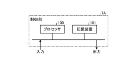
- FIG. 1 is a diagram showing the configuration of a motor drive system including the power conversion device according to the first embodiment
- FIG. FIG. 2 is a diagram showing the configuration of a control unit included in the power converter according to the first embodiment
- FIG. 2 is a diagram showing a hardware configuration example of a control unit included in the power converter according to the first embodiment
- 1 is a block diagram showing an example of a software configuration in a control unit included in the power converter according to Embodiment 1
- FIG. For explaining the correspondence data indicating the relationship between the motor rotation speed and the ripple current flowing through the second smoothing capacitor when the first interrupting device included in the power converter according to the first embodiment is opened. figure FIG.
- FIG. 4 is a diagram for explaining the number of motor revolutions set by the power converter according to the first embodiment using the correspondence data; 4 is a flow chart showing the procedure of control processing by the control unit of the power converter according to the first embodiment;
- FIG. 2 shows a configuration of a motor drive system including a power conversion device according to a second embodiment; The figure which shows the structure of the control part with which the power converter device concerning Embodiment 2 is equipped.
- 9 is a flow chart showing the procedure of control processing by the control unit of the power conversion device according to the third embodiment;
- the figure which shows the structure of the control part with which the power converter device concerning Embodiment 4 is equipped
- a block diagram showing an example of a software configuration in a control unit included in a power converter according to a fourth embodiment. 10 is a flowchart showing the procedure of control processing by the control unit of the power conversion device according to the fourth embodiment;
- FIG. 11 is a diagram showing another configuration example of the motor drive system including the power conversion device according to the fourth embodiment;
- a power conversion device, a motor drive system, and a power conversion method according to embodiments of the present disclosure will be described below in detail based on the drawings.
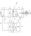
- FIG. 1 is a diagram showing the configuration of a motor drive system including a power conversion device according to a first embodiment.
- a motor drive system 301 is connected to the AC power supply 1 .
- a motor drive system 301 includes a power converter 10 , a motor 6 , and a current detector 32 .
- the motor drive system 301 is a system that converts input power into desired output power by the power converter 10 and supplies the converted power to the motor 6 .
- AC power supply 1 inputs AC power to power converter 10
- motor 6 is driven by the three-phase power generated by power converter 10 .
- the power conversion device 10 is a motor control device that controls the motor 6 by supplying electric power to the motor 6 .
- the power conversion device 10 includes a first converter circuit 2 , a first smoothing section 11 , an inverter circuit 5 and a first cutoff device 21 .
- the first smoothing section 11 has a first smoothing capacitor 3 and a second smoothing capacitor 4 .
- the power conversion device 10 also includes a first voltage detector 31 and a control section 7A. Based on the detection signals from the first voltage detector 31 and the current detector 32, the control unit 7A controls opening/closing of the first breaker 21 and on/off of each switching element of the inverter circuit 5.
- FIG. 1 A first voltage detector 31 and a control section 7A.
- the AC power supply 1 is a commercial AC system, a private generator, or the like.
- the motor 6 includes a three-phase Y-connected stator in which three-phase windings composed of a U-phase winding, a V-phase winding, and a W-phase winding are connected in a Y-shape, and a permanent magnet rotor. permanent magnet motor.
- the AC power supply 1 and the motor 6 are not limited to the configurations described above.
- the stator in the motor 6 may be a three-phase ⁇ -connected stator in which three-phase windings are connected in a ⁇ -shape. .
- the first converter circuit 2 converts the AC voltage from the AC power supply 1 into a DC voltage.
- the first converter circuit 2 is a diode rectifier circuit in which four diode elements are bridge-connected.
- the diode element used in the first converter circuit 2 is not limited to the type of fast recovery diode (FRD: Fast Recovery Diode) or soft recovery diode (SBD: Soft Recovery Diode).
- the diode element used in the first converter circuit 2 may be an element using a material such as SiC (Silicon Carbide), GaN (Gallium Nitride), or Ga2O3 (Gallium oxide).
- the first converter circuit 2 may be a circuit including a booster circuit, a step-down circuit, a step-up/step-down circuit, etc. using switching elements.
- the AC power supply 1 and the first converter circuit 2 are connected via connection lines 61 and 62 .
- the first converter circuit 2 and the inverter circuit 5 are connected via connection lines 63 and 64 .
- connection point 51 arranged on the connection line 63 and the connection point 53 arranged on the connection line 64 are connected via the connection line 65 .
- connection point 52 arranged on the connection line 63 and the connection point 54 arranged on the connection line 64 are connected via the connection line 66 .
- the connection point 52 is a connection point on the rear stage side of the connection point 51
- the connection point 54 is a connection point on the rear stage side of the connection point 53 .
- the first cutoff device 21 and the first smoothing capacitor 3 are connected in series on the connection line 65 . That is, the connection point 51 is connected to the connection point 53 via the first cutoff device 21 and the first smoothing capacitor 3 .
- the second smoothing capacitor 4 is arranged on the connection line 66 . That is, the connection point 52 is connected to the connection point 54 via the second smoothing capacitor 4 .
- the first smoothing capacitor 3 and the second smoothing capacitor 4 are connected in parallel with each other.
- the first voltage threshold is a value equal to or higher than the second voltage threshold (first voltage threshold ⁇ second voltage threshold)
- the first voltage threshold which is the withstand voltage of the first smoothing capacitor (low voltage capacitor) 3
- the breakdown voltage is the same value as the second voltage threshold.
- the second breakdown voltage which is the breakdown voltage of the second smoothing capacitor 4
- the first smoothing capacitor 3 and the second smoothing capacitor 4 smooth the DC voltage converted by the first converter circuit 2 into a stable DC voltage of a constant magnitude.
- first smoothing capacitor 3 and the second smoothing capacitor 4 are such that the ripple current flowing through each smoothing capacitor is Capacitance that is equal to or less than the rated ripple current and that the ripple current flowing through the second smoothing capacitor 4 is equal to or less than the rated ripple current for at least one rotational speed condition when the first breaker 21 is open.
- the first smoothing capacitor 3 and the second smoothing capacitor 4 satisfy all predetermined rotational speed conditions when the first shutoff device 21 is closed, and the first shutoff device 21 is It has a withstand voltage and a capacity that, when open, meet at least one speed condition.
- the amount of ripple (ripple voltage) of the voltage applied to each smoothing capacitor is determined by the chemical properties of the smoothing capacitor (for example, 20 to 40%). It has a withstand voltage and a capacity that are equal to or less than the value obtained by multiplying the withstand voltage of the capacitor (multiplied value).
- the power conversion device 10 can achieve optimum operation with the required capacitor capacity.
- the first smoothing section 11 is not limited to the above configuration, and may have any configuration as long as it can appropriately smooth the voltage.
- the configuration of the first smoothing unit 11 is such that three or more smoothing capacitors including the first smoothing capacitor 3 and the second smoothing capacitor 4 are connected in parallel, and the breakdown voltage is equal to or lower than the second voltage threshold.
- a configuration in which a cutoff device is connected in series to all the smoothing capacitors may be employed. With this configuration, the power conversion device 10 can realize optimum operation with a capacitor capacity as required.
- at least one of the first smoothing capacitor 3 and the second smoothing capacitor 4 may be configured by connecting a plurality of smoothing capacitors in series. Even when the first smoothing section 11 includes three or more smoothing capacitors connected in parallel, each smoothing capacitor has the withstand voltage and capacity described above.
- a mechanical relay is used for the first interrupting device 21, but a switching element made of a semiconductor including a wide bandgap semiconductor may be used.
- the first blocking device 21 includes an IGBT (Insulated Gate Bipolar Transistor), a MOSFET (Metal Oxide Semiconductor Field Effect Transistor), a SiC-MOSFET, a GaN-FET, a GaN-HEMT (High Electron Mobility Transistor). ), Ga2O3-MOSFET A switching element such as may be used.
- the inverter circuit 5 converts the DC voltage, which is converted into a DC voltage by the first converter circuit 2 and smoothed by the first smoothing capacitor 3 and the second smoothing capacitor 4, into an AC voltage and supplies it to the motor 6. .
- the power conversion device 10 can drive the motor 6 at a desired rotation speed (rotational speed) by controlling the AC voltage output from the inverter circuit 5, that is, the AC power.
- the switching elements made of a semiconductor including a wide bandgap semiconductor included in the inverter circuit 5 are not limited to IGBTs and MOSFETs, and may be SiC-MOSFETs, GaN-FETs, GaN-HEMTs, or Ga2O3-MOSFETs.
- the first voltage detector 31 detects the voltage applied to the second smoothing capacitor 4 and outputs the detected value as the detected value Vdc1 to the control section 7A.
- the voltage applied to the second smoothing capacitor 4 and the voltage applied to the first smoothing capacitor 3 are the same. Therefore, the first voltage detector 31 may detect the voltage applied to the first smoothing capacitor 3 .
- a detection value Vdc1 detected by the first voltage detector 31 is a first detection value.
- the current detector 32 is arranged on a connection line connecting the inverter circuit 5 and the motor 6, detects a phase current flowing from the inverter circuit 5 to the motor 6, and outputs the detected value to the control unit 7A as the detected value Iuvw. do.
- the current detector 32 may be a current detector using a current transformer called a CT (Current Transformer) or a current detector using a shunt resistor.
- FIG. 2 is a diagram showing the configuration of a control unit included in the power converter according to the first embodiment.
- Control unit 7A included in power converter 10 of Embodiment 1 receives detection value Vdc1 sent from first voltage detector 31 .
- the control unit 7A also receives the detection value Iuvw sent from the current detector 32 .
- control unit 7A transmits the switching signal X to the first cutoff device 21 based on the detection value Vdc1 of the first voltage detector 31.
- the switching signal X is a signal for switching the open/closed state of the first blocking device 21 .
- control unit 7A transmits drive signals S1 to S6 to each switching element of the inverter circuit 5 based on the detection value Vdc1 of the first voltage detector 31 and the detection value Iuvw of the current detector 32.
- the drive signals S1 to S6 are signals for controlling ON and OFF of each switching element of the inverter circuit 5 .
- the control section 7A can control the opening and closing of the first interrupting device 21 and the ON and OFF of each switching element of the inverter circuit 5 .
- the control unit 7A When the first converter circuit 2 includes a switching element, the control unit 7A outputs the driving signals S1 to S6 for controlling ON and OFF of each switching element of the first converter circuit 2 to the first converter. Send to circuit 2.
- FIG. 3 is a diagram showing a hardware configuration example of a control unit included in the power converter according to the first embodiment.
- the control section 7A is configured using a processing circuit such as a microcomputer.
- the control section 7A is configured using a processor 100 and a storage device 101 .
- the storage device 101 includes a volatile storage device such as a random access memory and a non-volatile auxiliary storage device such as a flash memory.
- the storage device 101 may include an auxiliary storage device such as a hard disk instead of the flash memory.
- control unit 7A When the control unit 7A is composed of the processor 100 and the storage device 101, each function of the control unit 7A is implemented by software, firmware, or a combination of software and firmware. Software or firmware is written as a program and stored in the storage device 101 .
- the processor 100 executes the program input from the storage device 101 to output the switching signal X and the drive signals S1 to S6.
- the program is input from the auxiliary storage device to the processor 100 via the volatile storage device.
- This program can also be said to be a program for causing the control unit 7A to execute each function realized by the processing circuit.
- This program may be provided by a storage medium storing the program, or may be provided by other means such as a communication medium.
- the processor 100 may output data such as calculation results to the volatile storage device of the storage device 101, or may store the data in an auxiliary storage device via the volatile storage device.
- processor 100 is a CPU (also called a central processing unit, processing unit, arithmetic unit, microprocessor, microcomputer, DSP (Digital Signal Processor)) or system LSI (Large Scale Integration).
- CPU also called a central processing unit, processing unit, arithmetic unit, microprocessor, microcomputer, DSP (Digital Signal Processor)) or system LSI (Large Scale Integration).
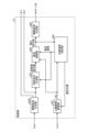
- FIG. 4 is a block diagram showing an example of the software configuration within the control unit provided in the power converter according to Embodiment 1.
- the software in the control unit 7A includes a position/velocity identification unit 200, a dq-axis coordinate conversion unit 201, an open/close signal generation unit 202A, a rotation command generation unit 203, a current control unit 204, and a drive signal generation unit 205.
- a position/velocity identification unit 200 includes a position/velocity identification unit 200, a dq-axis coordinate conversion unit 201, an open/close signal generation unit 202A, a rotation command generation unit 203, a current control unit 204, and a drive signal generation unit 205.
- the position/speed specifying unit 200 uses the voltage command value output from the current control unit 204 and the dq-axis current Idq output from the dq-axis coordinate conversion unit 201 to determine the magnetic poles of the motor 6. Estimate position and rotational velocity. As such an estimation method, an estimation method called an adaptive observer is generally known. The estimation method executed by the position/speed identification unit 200 is not limited to the above estimation method, and any estimation method may be used as long as the magnetic pole position and rotation speed of the motor 6 can be appropriately estimated. . Furthermore, a position detector may be attached to the motor 6 and used as the position/speed identifying section 200 .
- the position/velocity identification unit 200 outputs the estimated magnetic pole position (estimated position) to the dq-axis coordinate conversion unit 201 .
- the position/speed specifying unit 200 outputs the estimated rotation speed (estimated speed) to the rotation command generation unit 203 and the current control unit 204 .
- the dq-axis coordinate conversion unit 201 receives the detected value Iuvw sent from the current detector 32 .
- the dq-axis coordinate conversion unit 201 converts the detection value Iuvw of the current detector 32 into a current value (dq-axis current Idq).
- the dq-axis coordinates are a coordinate system generally used for vector control of a rotating body such as the motor 6 .
- the dq-axis coordinate transformation unit 201 outputs the dq-axis current Idq to the position/speed determination unit 200 and the current control unit 204 .
- the switching signal generator 202A receives the detection value Vdc1 sent from the first voltage detector 31.
- the switching signal generator 202A compares the second voltage threshold ( ⁇ the first voltage threshold) with the detected value Vdc1.
- generation parts produce
- the switching signal generator 202A generates the switching signal X for closing the first blocking device 21 when the detected value Vdc1 is smaller than the second voltage threshold.
- the switching signal generator 202A transmits the generated switching signal X to the first blocking device 21 and the rotation command generator 203 .
- the method of generating the switching signal X by the switching signal generation unit 202A is not limited to the above-described generation method, and any generation method may be used as long as it can generate the switching signal X appropriately.
- the switching signal generation unit 202A closes the first blocking device 21 when the first blocking device 21 is opened for a specific time or more. may be generated.
- the rotation command generator 203 generates a rotation speed command value for the motor 6 based on the switching signal X output from the open/close signal generator 202A. Specifically, when the switching signal X is a signal instructing to close the first shutoff device 21, the rotation command generator 203 freely sets the rotation speed command value according to the operation request of the motor 6. do. On the other hand, when the switching signal X is a signal instructing to open the first blocking device 21, the rotation command generation unit 203 sets the rotation speed command value of the motor 6 based on the correspondence data 80 described later. .
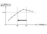
- FIG. 5 shows correspondence data showing the relationship between the motor rotation speed and the ripple current flowing through the second smoothing capacitor when the first breaker provided in the power converter according to the first embodiment is opened. It is a figure for explaining.
- the horizontal axis of the graph shown in FIG. 5 is the number of rotations of the motor 6, and the vertical axis is the ripple current flowing through the second smoothing capacitor 4.
- the correspondence data 80 is data indicating the correspondence between the motor rotation speed and the effective value of the ripple current flowing through the second smoothing capacitor 4 when the first cutoff device 21 is open.
- the correspondence data 80 may be represented graphically as shown in FIG. 5, or may be table data in which the motor rotation speed is associated with the effective value of the ripple current flowing through the second smoothing capacitor 4. may be shown.
- the correspondence data 80 can be obtained, for example, by techniques such as tests and simulations using the power conversion device 10 actually. In this case, by linearly interpolating between the actually acquired data or fitting with an appropriate function, the ripple current flowing through the second smoothing capacitor 4 even for the motor rotation speed for which data is not actually acquired is rms value can be obtained.
- the rotation command generation unit 203 When the rotation command generation unit 203 receives the switching signal X instructing to open the first blocking device 21 from the opening/closing signal generation unit 202A, the rotation command generation unit 203 converts the second smoothing capacitor 4 based on the correspondence data 80 to The motor rotation speed at which the effective value of the flowing ripple current is equal to or less than the rated ripple current Ic_lim is set.
- FIG. 6 is a diagram for explaining the motor rotation speed set by the power converter according to the first embodiment using the correspondence data.
- the rotation command generation unit 203 included in the control unit 7A of the power conversion device 10 reads the correspondence data 80 when receiving the switching signal X instructing to open the first cutoff device 21 .
- the rotation command generation unit 203 sets the motor rotation speed based on the correspondence data 80 .
- the rotation command generator 203 receives the switching signal X instructing the opening of the first blocking device 21 (hereinafter sometimes referred to as the opening instruction timing) at the motor rotation speed N1. 2 acquires the effective value of the ripple current flowing through the smoothing capacitor 4 from the correspondence data 80 .
- the motor rotation speed N1 at the time of the open instruction may be the rotation speed command value at the time of the open instruction, or may be calculated based on the estimated speed sent from the position/speed specifying unit 200 at the time of the open instruction.
- the rotation command generation unit 203 makes the effective value of the ripple current flowing through the second smoothing capacitor 4 equal to or less than the rated ripple current Ic_lim.
- a motor rotation speed (eg, motor rotation speed N2 in FIG. 6) is selected. That is, the rotation command generator 203 selects, from among the motor rotation speeds included in the correspondence data 80, the motor rotation speed at which the effective value of the ripple current is equal to or less than the rated ripple current Ic_lim.
- the rotation command generator 203 may, for example, select a motor rotation speed obtained by subtracting a specific value from the motor rotation speed at the rated ripple current Ic_lim, or may set the motor rotation speed at the rated ripple current Ic_lim to a specific value (from 0 A value of 1 or less) may be selected. It should be noted that the rotation command generation unit 203 may select the motor rotation speed not only by these selection methods but also by other selection methods. The rotation command generator 203 outputs the selected motor rotation speed as a rotation speed command value.
- the rotation command generator 203 continues operation with the current rotation speed command value.
- the correspondence data 80 shown in FIGS. 5 and 6 may be held within the control unit 7A, or may be held in the cloud or the like.
- an external device may determine the rotation speed command value based on the correspondence data 80.
- the power converter 10 receives the rotation speed command value determined by the external device and generates a voltage command value for driving the inverter circuit 5 .
- the power conversion device 10 may determine the rotation speed command value based on the correspondence data 80 .
- the correspondence data 80 shown in FIGS. 5 and 6 are not limited to the above configuration. If the correspondence data 80 is data that appropriately obtains the relationship between the motor rotation speed and the effective value of the ripple current flowing through the second smoothing capacitor 4 when the first cutoff device 21 is open, what kind of data can be used? may be configured to For example, the AC power supply 1 may be provided with a voltage detector, and the correspondence data 80 may be data that considers the dependency of the input voltage from the AC power supply 1 to the power converter 10 . Further, the correspondence data 80 may be data considering the dependence of the output voltage from the power conversion device 10 using Vdc1 obtained from the first voltage detector 31 .
- the current control unit 204 receives the dq-axis current Idq output from the dq-axis coordinate conversion unit 201, the rotation speed command value output from the rotation command generation unit 203, and the estimated speed of the motor 6 output from the position/speed identification unit 200. , a voltage command value for driving the inverter circuit 5 is generated.
- a generation method using a PI (Proportional Integral) controller is generally known.
- the method of generating the voltage command value by the current control unit 204 is not limited to the above-described generation method, and any generation method can be used as long as the dq-axis current Idq is appropriately controlled. good.
- the current control unit 204 may add a method of generating a voltage command value such as pulsating the dq-axis current Idq in order to intentionally pulsate the output of the motor 6 .
- the drive signal generation unit 205 generates drive signals S1 to S6 for PWM (Pulse Width Modulation) control of ON or OFF of each switching element of the inverter circuit 5 based on the voltage command value output from the current control unit 204.
- PWM control is a method generally used as a method for generating drive signals S1 to S6 for switching elements from a voltage command value or a current command value.
- the drive signal generator 205 transmits the generated drive signals S1 to S6 to the inverter circuit 5.
- control unit 7A An example of the process of generating the switching signal X and the rotation speed command value based on the detection value Vdc1 detected by the first voltage detector 31 will be described.
- FIG. 7 is a flow chart showing the procedure of control processing by the control unit of the power converter according to the first embodiment.
- the flowchart of FIG. 7 shows the processing procedure of the processing in which the control unit 7A generates the switching signal X and the rotation speed command value based on the detected value Vdc1.
- the switching signal generation section 202A of the control section 7A receives the detection value Vdc1 from the first voltage detector 31.
- the switching signal generator 202A compares the detection value Vdc1 of the first voltage detector 31 and the second voltage threshold, and determines whether the detection value Vdc1 of the first voltage detector 31 ⁇ the second voltage threshold. (step ST1).
- the switching signal generation unit 202A When the detection value Vdc1 of the first voltage detector 31 ⁇ the second voltage threshold (step ST1, Yes), the switching signal generation unit 202A outputs the switching signal X instructing the opening of the first blocking device 21. Generate and transmit (step ST2). In this case, the switching signal generator 202A transmits the generated switching signal X to the first blocking device 21 and the rotation command generator 203 .
- the rotation command generation unit 203 determines the effective value of the ripple current flowing through the second smoothing capacitor 4 at the motor rotation speed N1 at the time when the switching signal X instructing the opening of the first breaking device 21 is received. Obtained from data 80 . That is, the rotation command generator 203 acquires from the correspondence data 80 the effective value of the ripple current corresponding to the motor rotation speed N1 at the time of the open instruction.
- the rotation command generator 203 compares the effective value of the ripple current flowing through the second smoothing capacitor 4 at the motor rotation speed N1 with the rated ripple current. The rotation command generator 203 determines whether or not the effective value of the ripple current flowing through the second smoothing capacitor 4 > the rated ripple current at the motor rotation speed N1 (step ST3).
- the rotation command generation unit 203 determines the ripple current flowing through the second smoothing capacitor 4.
- a rotation speed command value for the motor 6 that makes the effective value equal to or less than the rated ripple current is selected (step ST4).
- the rotation command generator 203 selects, for example, the motor rotation speed N2 shown in FIG.
- Rotation command generation unit 203 outputs the selected rotation speed command value to current control unit 204 .
- Step ST3 If the effective value of the ripple current flowing through the second smoothing capacitor 4 at the motor rotation speed N1 ⁇ the rated ripple current (step ST3, No), the rotation command generator 203 continues the operation with the rotation speed command value as it is. (Step ST5). That is, the rotation command generation unit 203 outputs the current rotation speed command value to the current control unit 204 .
- step ST6 when the detection value Vdc1 of the first voltage detector 31 ⁇ the second voltage threshold (step ST1, No), the switching signal generation unit 202A instructs to close the first breaking device 21.
- a switching signal X is generated and transmitted (step ST6). That is, the switching signal generation unit 202A instructs to close the first blocking device 21 when the detected value Vdc1 ⁇ the second voltage threshold when the first blocking device 21 is opened.
- a signal X is generated and transmitted. In this case, the switching signal generator 202A transmits the generated switching signal X to the first blocking device 21 and the rotation command generator 203 .
- the rotation command generator 203 freely sets the rotation speed command value of the motor 6 according to the operation request (step ST7).
- Rotation command generation unit 203 outputs the set rotation speed command value to current control unit 204 .
- the current control section 204 controls the rotation speed command value output from the rotation command generation section 203, the dq-axis current Idq output from the dq-axis coordinate conversion section 201, and the position/speed determination section 200.
- a voltage command value is generated using the estimated speed of the motor 6 output from .
- Current control section 204 outputs the generated voltage command value to position/speed identification section 200 and drive signal generation section 205 .
- the drive signal generation unit 205 generates drive signals S1 to S6 for PWM-controlling ON/OFF of each switching element of the inverter circuit 5 based on the voltage command value output from the current control unit 204 .
- the drive signal generator 205 transmits the generated drive signals S1 to S6 to the inverter circuit 5.
- the first voltage detector 31 detects the voltage applied to the second smoothing capacitor 4 having the second breakdown voltage higher than the first voltage threshold. Detected as Vdc1. This detected value Vdc1 corresponds to the voltage applied to the first smoothing capacitor 3 .
- the control unit 7A controls the first cutoff device 21 connected in series with the first smoothing capacitor 3. open. Furthermore, the control unit 7A controls the rotation speed of the motor 6 so that the ripple current flowing through the second smoothing capacitor 4, whose breakdown voltage is higher than the first voltage threshold, is equal to or less than the rated ripple current.
- the power conversion device 10 suppresses the applied voltage of the first smoothing capacitor 3 to the withstand voltage or less, and suppresses the ripple current flowing through the second smoothing capacitor 4 to the rated ripple current or less, thereby achieving high reliability. operation becomes possible.
- the power converter 10 opens the first cutoff device 21 when the detected value Vdc1 detected by the first voltage detector 31 is greater than or equal to the second voltage threshold. ing. Furthermore, the power conversion device 10 controls the rotation speed of the motor 6 so that the ripple current flowing through the second smoothing capacitor 4 is equal to or less than the rated ripple current. Thereby, the power conversion device 10 can suppress the ripple current flowing through the second smoothing capacitor 4 to the rated ripple current or less. Therefore, the power conversion device 10 can suppress the deterioration of the life of the second smoothing capacitor 4 .
- Embodiment 2 will be described with reference to FIGS. 8 to 10.
- FIG. 1 in a motor drive system in which a second converter circuit is connected in parallel with a first converter circuit 2, a power conversion device 10 drives and controls a motor 6.
- FIG. 1 in a motor drive system in which a second converter circuit is connected in parallel with a first converter circuit 2, a power conversion device 10 drives and controls a motor 6.
- FIG. 8 is a diagram showing the configuration of a motor drive system including the power converter according to the second embodiment. 8 that achieve the same functions as those of the motor drive system 301 of Embodiment 1 shown in FIG. 1 are denoted by the same reference numerals, and overlapping descriptions are omitted.
- the reference numerals of the connection points 51 to 54 and the connection lines 63 to 66 are omitted.
- the motor drive system 302 includes a power conversion device 10, a motor 6, a current detector 32, and a drive section 40. That is, the motor drive system 302 includes a drive unit 40 in addition to the components of the motor drive system 301 .
- the drive unit 40 includes a second converter circuit 41 connected in parallel to the first converter circuit 2, a second smoothing unit 43 including a third smoothing capacitor 42, a second voltage detector 44, and a load 45 .
- the drive section 40 is connected to the connection lines 67 and 68 .
- the connecting line 67 is connected to the connecting point 55 on the connecting line 61 and the connecting line 68 is connected to the connecting point 56 on the connecting line 62 .
- the second converter circuit 41 is connected to the connection lines 67 and 68. Also, the second converter circuit 41 and the load 45 are connected via connection lines 69 and 70 .
- connection point 57 arranged on the connection line 69 and the connection point 58 arranged on the connection line 70 are connected via the connection line 71 .
- the third smoothing capacitor 42 is arranged on the connection line 71 . That is, the connection point 57 is connected to the connection point 58 via the third smoothing capacitor 42 .
- the power conversion device 10 includes a control unit 7B instead of the control unit 7A. Based on detection signals from the first voltage detector 31, the second voltage detector 44, and the current detector 32, the control unit 7B opens and closes the first breaker 21 and switches the inverter circuit 5. Controls the on and off of the element.
- the second converter circuit 41 is a diode rectifier circuit in which four diode elements are bridge-connected.
- the diode element used in the second converter circuit 41 is not limited to the types of fast recovery diodes and soft recovery diodes.
- a diode element used in the second converter circuit 41 may be an element using a material such as SiC, GaN, or Ga2O3.
- the second converter circuit 41 may be a circuit including a booster circuit, a step-down circuit, a step-up/step-down circuit, or the like using switching elements.
- the third breakdown voltage which is the breakdown voltage of the third smoothing capacitor 42, is greater than or equal to the second breakdown voltage of the second smoothing capacitor 4.
- the third smoothing capacitor 42 has a capacity such that the ripple current flowing through the third smoothing capacitor 42 is equal to or less than the rated ripple current under all predetermined rotational speed conditions.
- the third smoothing capacitor 42 has a breakdown voltage such that the amount of ripple of the applied voltage is equal to or less than the value obtained by multiplying the breakdown voltage of the smoothing capacitor by a ratio (for example, 20 to 40%) determined by the chemical properties of the smoothing capacitor. and capacity.
- the second smoothing section 43 is not limited to the above configuration, and may have any configuration as long as it can appropriately smooth the voltage.
- the configuration of the second smoothing section 43 (third smoothing capacitor 42) is such that the total breakdown voltage (third breakdown voltage) is equal to or higher than the second breakdown voltage of the second smoothing capacitor 4, and two or more A configuration (smoothing capacitor group) in which smoothing capacitors are connected in series may be employed.
- the second smoothing section 43 may have a configuration in which two or more smoothing capacitors having a withstand voltage equal to or higher than the second withstand voltage of the second smoothing capacitor 4 or the group of smoothing capacitors described above are connected in parallel.
- the load 45 like the inverter circuit 5 and the motor 6, is composed of an inverter circuit and a motor. Note that the load 45 is not limited to the configuration described above, and a load having any configuration may be used.
- the second voltage detector 44 detects the voltage applied to the third smoothing capacitor 42, and outputs the detected value as the detected value Vdc2 to the controller 7B.
- the detected value Vdc2 detected by the second voltage detector 44 is the second detected value.
- FIG. 9 is a diagram showing the configuration of a control unit included in the power converter according to the second embodiment.
- Control unit 7 ⁇ /b>B included in power converter 10 of the second embodiment receives detection value Vdc ⁇ b>1 sent from first voltage detector 31 .
- Control unit 7B also receives detection value Vdc2 sent from second voltage detector 44 .
- the control unit 7B receives the detection value Iuvw sent from the current detector 32 .
- control unit 7B transmits the switching signal X to the first cutoff device 21 based on the detection value Vdc1 of the first voltage detector 31 or the detection value Vdc2 of the second voltage detector 44. Further, the control unit 7B controls each of the inverter circuits 5 based on the detection value Vdc1 of the first voltage detector 31 or the detection value Vdc2 of the second voltage detector 44 and the detection value Iuvw of the current detector 32. Drive signals S1 to S6 are sent to the switching elements. Thereby, the control unit 7B can control the opening/closing of the first breaker 21 and the ON/OFF of each switching element of the inverter circuit 5 .
- the control unit 7B When the first converter circuit 2, the second converter circuit 41, or the load 45 includes switching elements, the control unit 7B outputs drive signals S1 to S6 for controlling on and off of these switching elements. to these switching elements.
- FIG. 10 is a block diagram showing an example of the software configuration within the control unit provided in the power converter according to Embodiment 2.
- FIG. 10 constituent elements that achieve the same functions as those of the control section 7A of Embodiment 1 shown in FIG.
- the software in the control unit 7B includes a position/velocity identification unit 200, a dq-axis coordinate conversion unit 201, an open/close signal generation unit 202B, a rotation command generation unit 203, a current control unit 204, and a drive signal generation unit 205.
- the software in the control unit 7B includes a switching signal generation unit 202B instead of the switching signal generation unit 202A, as compared with the software in the control unit 7A.
- the switching signal generator 202B receives at least one of the detected value Vdc1 sent from the first voltage detector 31 and the detected value Vdc2 sent from the second voltage detector 44.
- the power conversion device 10 When the first voltage detector 31 transmits the detection value Vdc1 to the switching signal generator 202B, the power conversion device 10 does not have to include the second voltage detector 44. Moreover, when the second voltage detector 44 transmits the detection value Vdc2 to the switching signal generation unit 202B, the power conversion device 10 does not have to include the first voltage detector 31 . That is, since the detected value Vdc1 and the detected value Vdc2 are substantially the same value, either one of the detected values Vdc1 and Vdc2 should be input to the switching signal generator 202B.
- the switching signal generation unit 202B converts one of the detection value Vdc1 of the first voltage detector 31 and the detection value Vdc2 of the second voltage detector 44 into a voltage value for generating the switching signal X (hereinafter referred to as (sometimes referred to as switching voltage value).
- the switching signal generator 202B compares the second voltage threshold and the switching voltage value.
- the switching signal generator 202B generates the switching signal X for opening the first blocking device 21 when the switching voltage value is equal to or higher than the second voltage threshold.
- the switching signal generator 202B generates the switching signal X for closing the first blocking device 21 when the switching voltage value is smaller than the second voltage threshold.
- the switching signal generator 202 ⁇ /b>B transmits the generated switching signal X to the first blocking device 21 and the rotation command generator 203 .
- the method of generating the switching signal X by the switching signal generation unit 202B is not limited to the above-described generation method, and any generation method may be used as long as it can generate the switching signal X appropriately.
- the switching signal generation unit 202B generates the first A switching signal X for opening the blocking device 21 may be generated.
- the switching signal generator 202B may adopt the average value of the detection value Vdc1 of the first voltage detector 31 and the detection value Vdc2 of the second voltage detector 44 as the switching voltage value.
- the opening/closing signal generation unit 202B closes the first blocking device 21 when the first blocking device 21 is opened for a specific time or more. may be generated.
- step ST1 differs from the processing procedure described with reference to FIG. 7 of the first embodiment. Specifically, in the first embodiment, the switching signal generation unit 202A determines whether or not the detection value Vdc1 of the first voltage detector 31 ⁇ the second voltage threshold. 2, it is determined whether or not the switching voltage value ⁇ the second voltage threshold.
- the first voltage detector 31 detects the voltage applied to the first smoothing capacitor 3, or the second voltage detector 44 detects the voltage applied to the third smoothing capacitor 42. Detects the applied voltage.
- the control unit 7B switches the first smoothing capacitor 3 is opened. Further, the control unit 7B controls the rotation speed of the motor 6 so that the ripple current flowing through the second smoothing capacitor 4, whose breakdown voltage is higher than the first voltage threshold, is equal to or less than the rated ripple current.
- the power conversion device 10 of the second embodiment can obtain the same effects as the power conversion device 10 of the first embodiment. That is, the power conversion device 10 in the second embodiment can operate with high reliability, and can suppress the life of the second smoothing capacitor 4 from being shortened.
- Embodiment 3 Next, Embodiment 3 will be described with reference to FIGS. 11 to 14.
- FIG. 1 a second breaker is arranged on the connection line 61 between the AC power supply 1 and the first converter circuit 2, and the power conversion device 10 opens and closes the second breaker. Control.
- FIG. 11 is a diagram showing the configuration of a motor drive system including a power conversion device according to the third embodiment.
- constituent elements in FIG. 11 constituent elements that achieve the same functions as those of the motor drive system 301 of Embodiment 1 shown in FIG.
- the reference numerals of the connection points 51 to 54 and the connection lines 63 to 66 are omitted.
- the motor drive system 303 includes the power conversion device 10 , the motor 6 , the current detector 32 and the second cutoff device 22 . That is, the motor drive system 303 includes the second cutoff device 22 in addition to the components of the motor drive system 301 .
- the second cutoff device 22 is arranged on the connection line 61 . That is, the second cutoff device 22 is arranged between the AC power supply 1 and the first converter circuit 2 .
- the second cutoff device 22 may be arranged inside the power conversion device 10 or may be arranged outside the power conversion device 10 .
- the power conversion device 10 includes a control unit 7C instead of the control unit 7A. Based on detection signals from the first voltage detector 31 and the current detector 32, the control unit 7C opens and closes the first breaker 21, opens and closes the second breaker 22, and switches the inverter circuit 5. Controls the on and off of the element.
- a mechanical relay is used for the second cutoff device 22 in the same manner as the first cutoff device 21, but a switching element made of a semiconductor including a wide bandgap semiconductor may be used. That is, the second cutoff device 22 may use switching elements such as IGBTs, MOSFETs, SiC-MOSFETs, GaN-FETs, GaN-HEMTs, or Ga2O3-MOSFETs.
- FIG. 12 is a diagram showing the configuration of a control unit included in the power converter according to the third embodiment.
- Control unit 7C included in power converter 10 of Embodiment 3 receives detection value Vdc1 sent from first voltage detector 31 . Also, the control unit 7C receives the detection value Iuvw sent from the current detector 32 .
- control unit 7C transmits a switching signal X to the first cutoff device 21 based on the detected value Vdc1. Also, the control unit 7C transmits a switching signal Y to the second blocking device 22 based on the detected value Vdc1. The switching signal Y is a signal for switching the open/closed state of the second blocking device 22 .
- Control unit 7C also transmits drive signals S1 to S6 to each switching element of inverter circuit 5 based on detected value Vdc1 and detected value Iuvw. Thereby, the control unit 7C can control opening/closing of the first interrupting device 21, opening/closing of the second interrupting device 22, and ON/OFF of each switching element of the inverter circuit 5.
- FIG. 13 is a block diagram showing an example of the software configuration within the control unit provided in the power conversion device according to Embodiment 3. As shown in FIG. Among the constituent elements in FIG. 13, constituent elements that achieve the same functions as those of the control section 7A of the first embodiment shown in FIG.
- the software in the control unit 7C includes a position/velocity identification unit 200, a dq-axis coordinate conversion unit 201, an open/close signal generation unit 202C, a rotation command generation unit 203, a current control unit 204, and a drive signal generation unit 205.
- the software in the control unit 7C includes a switching signal generation unit 202C instead of the switching signal generation unit 202A, compared with the software in the control unit 7A.
- the switching signal generator 202C receives the detection value Vdc1 sent from the first voltage detector 31.
- the switching signal generator 202 ⁇ /b>C compares the second voltage threshold with the detection value Vdc ⁇ b>1 of the first voltage detector 31 .
- generation parts produce
- the switching signal generator 202C generates the switching signal X for closing the first blocking device 21 when the detected value Vdc1 is smaller than the second voltage threshold.
- the switching signal generation unit 202C sets a third voltage threshold (first voltage threshold ⁇ third voltage threshold ⁇ second withstand voltage) and the detected value Vdc1.
- generation parts produce
- the switching signal generator 202C generates the switching signal Y for closing the second blocking device 22 when the detected value Vdc1 is smaller than the third voltage threshold.
- the switching signal generator 202C transmits the generated switching signal X to the first blocking device 21 and the rotation command generator 203 . Also, the switching signal generator 202 ⁇ /b>C transmits the generated switching signal Y to the second blocking device 22 .
- the opening/closing signal generation unit 202C has a function of closing the blocking devices in order.
- the method of generating the switching signals X and Y by the opening/closing signal generation unit 202C is not limited to the above generation method, and any generation method can be used as long as it can generate the switching signals X and Y appropriately. There may be.
- control unit 7C an example of the process of generating the switching signals X and Y and the rotation speed command value based on the detection value Vdc1 detected by the first voltage detector 31 will be described.
- FIG. 14 is a flow chart showing the procedure of control processing by the control unit of the power converter according to the third embodiment.
- the flow chart of FIG. 14 shows a process in which the control unit 7C generates the switching signals X and Y and the rotational speed command value based on the detected value Vdc1.
- the open/close signal generation unit 202C of the control unit 7C determines the open/closed states of the first shutoff device 21 and the second shutoff device 22 at the end of the previous process. Specifically, the opening/closing signal generation unit 202C determines that both the first shutoff device 21 and the second shutoff device 22 (hereinafter sometimes referred to as the first and second shutoff devices) are open at the end of the previous process. It is determined whether or not it is in the state of being held (step ST11).
- the first and second blocking devices are Gets the duration of the open together state.
- the duration of the state in which both the first and second blocking devices are opened is measured using a timer function or the like.
- the opening/closing signal generation unit 202C determines whether or not the duration of the state in which both the first and second blocking devices are opened is less than a specific time (step ST12a). In other words, the opening/closing signal generator 202C determines whether the continuation of the state in which both the first and second blocking devices are opened has passed the specific time.
- the opening/closing signal generation unit 202C determines that the duration of the state in which both the first and second blocking devices are opened is less than the specific time (step ST12a, Yes), the first and second blocking devices are kept open (step ST13). That is, the opening/closing signal generator 202C generates switching signals X and Y for continuing the state in which both the first and second blocking devices are opened.
- the switching signal generator 202C transmits the generated switching signal X to the first blocking device 21 and the rotation command generator 203 . Also, the switching signal generator 202 ⁇ /b>C transmits the generated switching signal Y to the second blocking device 22 .
- the opening/closing signal generation unit 202C determines that the duration of the state in which both the first and second blocking devices are opened is equal to or longer than the specific time (step ST12a, No), the first blocking device 21 and the second blocking device 202C 2 is closed in order of the breaking device 22 (step ST14). This allows the motor drive system 303 to return to normal operation.
- the opening/closing signal generation unit 202C can prevent excessive inrush current from flowing into the power converter 10 by closing the first and second breaking devices 21 and 22 in this order.
- the switching signal generation unit 202C closes the first breaking device 21 and the second breaking device 22 in this order, and then compares the detection value Vdc1 of the first voltage detector 31 with the third voltage threshold. . Then, the switching signal generator 202C determines whether or not the detection value Vdc1 of the first voltage detector 31 ⁇ the third voltage threshold (step ST15).
- the switching signal generation unit 202C instructs to open the second blocking device 22.
- a signal Y is generated and transmitted to the second cutoff device 22 (step ST16).
- the controller 7C stops the operation of the motor 6 (step ST17).
- step ST11 when the opening/closing signal generation unit 202C determines that either the first or second blocking device was closed at the end of the previous process (step ST11, No), 7 C of control parts perform the process after step ST15.
- step ST15 when the switching signal generation unit 202C determines that the detection value Vdc1 of the first voltage detector 31 ⁇ the third voltage threshold (step ST15, No), the switching signal generation unit 202C , a switching signal Y instructing to close the second blocking device 22 is generated and transmitted to the second blocking device 22 (step ST18).
- control unit 7C executes the processing of steps ST1 to ST7 described with reference to FIG. That is, the control section 7C generates and transmits the switching signal X and the rotation speed command value (steps ST1 to ST7).
- the switching signal generation unit 202C executed both steps ST16 and ST17 when the detection value Vdc1 of the first voltage detector 31 ⁇ the third voltage threshold, but the switching signal generation unit 202C , at least one of steps ST16 and ST17 may be executed.
- control unit 7C controls the detection value Vdc1 of the voltage applied to the second smoothing capacitor 4 whose withstand voltage is higher than the first voltage threshold to be the second voltage threshold higher than the first voltage threshold. 2, the second cutoff device 22 is opened and the operation of the motor 6 is stopped.
- the control unit 7C when the detected value Vdc1 of the voltage applied to the second smoothing capacitor 4 is greater than or equal to the second voltage threshold, connects the first smoothing capacitor 3 in series with Open the connected first shutoff device 21 . Furthermore, the control unit 7C controls the rotation speed of the motor 6 so that the ripple current flowing through the second smoothing capacitor 4 is equal to or less than the rated ripple current. Therefore, similarly to the first embodiment, the power conversion device 10 can operate with high reliability, and can suppress the life of the second smoothing capacitor 4 from being shortened.
- Embodiment 4 Next, Embodiment 4 will be described with reference to FIGS. 15 to 19.
- FIG. In Embodiment 4, the configuration of the motor drive system is a configuration in which the motor drive systems 302 and 303 are combined. That is, in the motor drive system of Embodiment 4, the second converter circuit 41 is connected in parallel to the first converter circuit 2, and the connection line 61 between the AC power supply 1 and the first converter circuit 2 A second shut-off device 22 is arranged in the .
- FIG. 15 is a diagram showing the configuration of a motor drive system including a power conversion device according to the fourth embodiment.
- constituent elements that achieve the same functions as those of the motor drive system 302 of the second embodiment or the motor drive system 303 of the third embodiment are denoted by the same reference numerals, and duplicate descriptions are omitted. do.
- the reference numerals of the connection points 51-54, 57, 58 and the connection lines 63-70 are omitted.
- the motor drive system 304 includes the power converter 10 , the motor 6 , the current detector 32 , the second cutoff device 22 and the drive section 40 . That is, the motor drive system 304 includes the second shutoff device 22 in addition to the components of the motor drive system 302 .
- the second cutoff device 22 is arranged between the connection point 55 and the first converter circuit 2 on the connection line 61 .
- the second cutoff device 22 may be arranged inside the power conversion device 10 or may be arranged outside the power conversion device 10 .
- the power conversion device 10 includes a control unit 7D instead of the control unit 7A. Based on the detection signals from the first voltage detector 31, the second voltage detector 44, and the current detector 32, the control unit 7D opens and closes the first breaker 21 and the second breaker 22. It controls opening/closing and on/off of each switching element of the inverter circuit 5 .
- FIG. 16 is a diagram showing the configuration of a control unit included in the power converter according to the fourth embodiment.
- Control unit 7 ⁇ /b>D included in power converter 10 of the fourth embodiment receives detection value Vdc ⁇ b>1 sent from first voltage detector 31 . Further, control unit 7D receives detection value Vdc2 sent from second voltage detector 44 . Also, the control unit 7D receives the detection value Iuvw sent from the current detector 32 .
- control unit 7D transmits the switching signal X to the first cutoff device 21 based on the detection value Vdc1 of the first voltage detector 31. Further, the control unit 7D transmits a switching signal Y to the second cutoff device 22 based on the detection value Vdc2 of the second voltage detector 44. FIG. Further, the control unit 7D transmits drive signals S1 to S6 to each switching element of the inverter circuit 5 based on the detection value Vdc1 of the first voltage detector 31 and the detection value Iuvw of the current detector 32. do. Thereby, the control unit 7D can control opening/closing of the first interrupting device 21, opening/closing of the second interrupting device 22, and ON/OFF of each switching element of the inverter circuit 5.
- the control unit 7D When the first converter circuit 2, the second converter circuit 41, or the load 45 includes switching elements, the control unit 7D outputs drive signals S1 to S6 for controlling on and off of these switching elements. to these switching elements.
- FIG. 17 is a block diagram showing an example of the software configuration within the control unit provided in the power converter according to Embodiment 4.
- FIG. 17 constituent elements that achieve the same functions as those of the control section 7A of the second embodiment shown in FIG.
- the software in the control unit 7D includes a position/velocity identification unit 200, a dq-axis coordinate conversion unit 201, an open/close signal generation unit 202D, a rotation command generation unit 203, a current control unit 204, and a drive signal generation unit 205.
- the software in the control section 7D includes a switching signal generation section 202D instead of the switching signal generation section 202A, as compared with the software in the control section 7A.
- the switching signal generator 202D receives the detection value Vdc1 sent from the first voltage detector 31 and the detection value Vdc2 sent from the second voltage detector 44.
- the switching signal generator 202D compares the second voltage threshold value with the detection value Vdc2 of the second voltage detector 44 . When the detected value Vdc2 is greater than or equal to the second voltage threshold, the switching signal generator 202D closes the first and second breaking devices 21 and 22 in that order.
- the switching signal generator 202D also compares the detected value Vdc1 with a third voltage threshold that is greater than the first voltage threshold and equal to the second withstand voltage of the second smoothing capacitor 4 .
- the switching signal generator 202D generates a switching signal Y for opening the second blocking device 22 when the detected value Vdc1 is greater than or equal to the third voltage threshold.
- the switching signal generator 202D generates the switching signal Y for closing the second blocking device 22 when the detected value Vdc1 is smaller than the third voltage threshold.
- the switching signal generator 202D compares the second voltage threshold with the detection value Vdc2 of the second voltage detector 44 . Similarly to the switching signal generating section 202A, the switching signal generating section 202D generates the switching signal X for opening the first blocking device 21 when the detected value Vdc2 is equal to or higher than the second voltage threshold. On the other hand, the switching signal generator 202D generates the switching signal X for closing the first blocking device 21 when the detected value Vdc2 is smaller than the second voltage threshold.
- the opening/closing signal generation unit 202D transmits the generated switching signal X to the first blocking device 21 and the rotation command generation unit 203. Also, the switching signal generator 202 ⁇ /b>D transmits the generated switching signal Y to the second blocking device 22 .
- the switching signal generating section 202D has both the function of the switching signal generating section 202B and the function of the switching signal generating section 202C.
- the method of generating the switching signals X and Y by the opening/closing signal generation unit 202D is not limited to the above-described generation method, and any generation method can be used as long as it can generate the switching signals X and Y appropriately. There may be.
- the switching signals X, Y and the rotation speed are determined based on the detection value Vdc1 detected by the first voltage detector 31 and the detection value Vdc2 detected by the second voltage detector An example of processing for generating command values will be described.
- FIG. 18 is a flowchart showing the procedure of control processing by the control unit of the power converter according to the fourth embodiment.
- the flowchart of FIG. 18 shows the processing in which the control unit 7D generates the switching signals X and Y and the rotation speed command value based on the detected value Vdc1 and the detected value Vdc2.
- the control unit 7C executes the process of step ST12a, while the control unit 7D executes the process of step ST12b.
- the processing of steps ST11, ST13 to ST18, ST1 to ST7 executed by the control unit 7C and the processing of steps ST11, ST13 to 18, ST1 to ST7 executed by the control unit 7D are the same processing and are performed in the same processing procedure. executed.
- control unit 7D determines that both the first and second blocking devices were open at the end of the previous process (step ST11, Yes)
- both the first and second blocking devices are opened.
- the switching signal generation unit 202D compares the detection value Vdc2 of the second voltage detector 44 and the second voltage threshold, and determines that the detection value Vdc2 of the second voltage detector 44 ⁇ the second voltage threshold. It is determined whether or not there is (step ST12b).
- step ST12b When the detection value Vdc2 of the second voltage detector 44 ⁇ the second voltage threshold (step ST12b, Yes), the switching signal generator 202D executes the process of step ST13. On the other hand, when the detection value Vdc2 of the second voltage detector 44 ⁇ the second voltage threshold (step ST12b, No), the switching signal generation section 202D executes the processes after step ST14. This eliminates the need for the controller 7D to stop the operation of the motor 6 for a specific time.
- FIG. 19 is a diagram showing another configuration example of the motor drive system provided with the power converter according to the fourth embodiment.
- the constituent elements in FIG. 19 the constituent elements that achieve the same functions as those of the motor drive system 304 shown in FIG.
- the reference numerals of the connection points 51 to 54, 57 and 58 and the connection lines 63 to 70 are omitted.
- the motor drive system 305 includes the power conversion device 10, the motor 6, the current detector 32, the second cutoff device 22, and the drive section 40, similar to the motor drive system 304.
- the second cutoff device 22 is arranged between the connection point 55 and the AC power supply 1 on the connection line 61 .
- the power converter 10 performs the same operation in the motor drive system 305 as in the motor drive system 304 .
- the preferred operation of motor drive system 305 can be realized by combining the operations shown in the first to fourth embodiments.
- the switching voltage value may be used. That is, the switching signal generator 202D may compare the second voltage threshold and the detection value Vdc1 instead of comparing the second voltage threshold and the detection value Vdc2.
- control unit 7D controls the detection value Vdc1 of the voltage applied to the second smoothing capacitor 4 whose withstand voltage is higher than the first voltage threshold to be the second voltage threshold higher than the first voltage threshold. 2, the second cutoff device 22 is opened and the operation of the motor 6 is stopped.
- the control unit 7D sets the withstand voltage to the second voltage threshold.
- the first interrupting device 21 connected in series with the first smoothing capacitor 3 is opened.
- the control unit 7D controls the rotation speed of the motor 6 so that the ripple current flowing through the second smoothing capacitor 4, whose breakdown voltage is higher than the first voltage threshold, is equal to or less than the rated ripple current. Therefore, similarly to the first embodiment, the power conversion device 10 can operate with high reliability, and can suppress the life of the second smoothing capacitor 4 from being shortened.
Landscapes
- Engineering & Computer Science (AREA)
- Power Engineering (AREA)
- Inverter Devices (AREA)
Abstract
A power conversion device (10) comprises: a first converter circuit (2) for converting AC voltage to DC voltage; an inverter circuit (5) for converting the DC voltage to AC voltage; a first smoothing unit (11) which is connected between the first converter circuit and the inverter circuit and in which, when a first voltage threshold is set to a value greater than or equal to a second voltage threshold, a first smoothing capacitor (3) having a first withstand voltage equal to the second voltage threshold and a second smoothing capacitor (4) having a second withstand voltage greater than the first voltage threshold are connected in parallel; a first blocking device (21) connected in series with the first smoothing capacitor; a first voltage detector (31) for detecting a voltage applied to the second smoothing capacitor; and a control unit (7A) which, when a first detection value detected by the first voltage detector is greater than or equal to the second voltage threshold, opens the first blocking device and controls the rotational speed of a motor so that the ripple current flowing through the second smoothing capacitor becomes less than or equal to a rated ripple current..
Description
本開示は、入力電力を所望の出力電力に変換する電力変換装置、モータ駆動システム、および電力変換方法に関する。
The present disclosure relates to a power converter, a motor drive system, and a power conversion method that convert input power into desired output power.
入力電力を所望の出力電力に変換する電力変換装置の1つに、ダイオード整流回路などのコンバータ回路に平滑コンデンサを接続した構成の電力変換装置がある。この電力変換装置に対しては、コンバータ回路への交流入力電圧が大きい場合に、平滑コンデンサを高電圧から保護する検討がなされている。
One type of power conversion device that converts input power into desired output power is a power conversion device that has a configuration in which a smoothing capacitor is connected to a converter circuit such as a diode rectifier circuit. For this power converter, studies have been made to protect the smoothing capacitor from high voltage when the AC input voltage to the converter circuit is high.
例えば、特許文献1に記載の電力変換装置は、高耐圧かつ小容量である平滑コンデンサ(第1コンデンサ)と、低耐圧かつ大容量である平滑コンデンサ(第2コンデンサ)とが並列に接続されている。この特許文献1に記載の電力変換装置は、第1コンデンサの両端の電位差が基準値以上である場合に、第2コンデンサに直列に接続されているスイッチをオフにすることで、第2コンデンサを保護している。
For example, in the power conversion device described in Patent Document 1, a high-voltage, small-capacity smoothing capacitor (first capacitor) and a low-voltage, large-capacity smoothing capacitor (second capacitor) are connected in parallel. there is The power conversion device described in Patent Document 1 turns off the switch connected in series with the second capacitor when the potential difference between both ends of the first capacitor is equal to or greater than the reference value, thereby turning off the second capacitor. are protecting.
しかしながら、上記特許文献1の技術では、第1コンデンサの両端の電位差が基準値以上となった場合に、小容量である第1コンデンサのみで動作を継続することになる。このとき、電力変換装置が、コンバータ回路および平滑コンデンサに加えて、インバータ回路およびモータが接続された構成の場合、平滑コンデンサの容量低減に伴って各種電圧および各種電流が脈動する。これにより、特許文献1の電力変換装置では、平滑コンデンサのリプル電流が増大し、定格リプル電流を超過する場合がある。定格リプル電流を超過するリプル電流が長時間にわたって平滑コンデンサに流れると、平滑コンデンサの寿命が大幅に低下するという問題があった。
However, with the technique of Patent Document 1, when the potential difference between both ends of the first capacitor becomes equal to or greater than the reference value, the operation continues only with the first capacitor, which has a small capacity. At this time, if the power conversion device has a configuration in which an inverter circuit and a motor are connected in addition to a converter circuit and a smoothing capacitor, various voltages and various currents pulsate as the capacity of the smoothing capacitor decreases. As a result, in the power conversion device of Patent Literature 1, the ripple current of the smoothing capacitor may increase and exceed the rated ripple current. When a ripple current exceeding the rated ripple current flows in the smoothing capacitor for a long time, there is a problem that the service life of the smoothing capacitor is greatly reduced.
本開示は、上記に鑑みてなされたものであって、コンバータ回路に接続された平滑コンデンサの寿命が低下することを抑制できる電力変換装置を得ることを目的とする。
The present disclosure has been made in view of the above, and an object thereof is to obtain a power conversion device capable of suppressing a decrease in life of a smoothing capacitor connected to a converter circuit.
上述した課題を解決し、目的を達成するために、本開示の電力変換装置は、交流電源からの交流電圧を直流電圧に変換する第1のコンバータ回路と、第1のコンバータ回路によって変換された直流電圧を交流電圧に変換してモータに供給するインバータ回路と、を備える。また、本開示の電力変換装置は、第1のコンバータ回路とインバータ回路との間に接続されるとともに、第1の電圧閾値を第2の電圧閾値以上の値とした場合に、第2の電圧閾値と同じ第1の耐圧を有した第1の平滑コンデンサ、および第1の電圧閾値より大きい第2の耐圧を有した第2の平滑コンデンサが並列に接続された第1の平滑部と、第1の平滑コンデンサに直列に接続された第1の遮断装置と、第2の平滑コンデンサの印加電圧を検出する第1の電圧検出器と、を備える。また、本開示の電力変換装置は、第1の電圧検出器によって検出された印加電圧の検出値である第1の検出値が、第2の電圧閾値以上である場合に、第1の遮断装置を開き、且つ第2の平滑コンデンサに流れるリプル電流が定格リプル電流以下となるようにモータの回転数を制御する制御部を備える。
In order to solve the above-described problems and achieve the object, the power conversion device of the present disclosure includes a first converter circuit that converts an AC voltage from an AC power supply to a DC voltage, and a DC voltage converted by the first converter circuit. and an inverter circuit that converts the DC voltage into an AC voltage and supplies the AC voltage to the motor. Further, the power conversion device of the present disclosure is connected between the first converter circuit and the inverter circuit, and when the first voltage threshold is set to a value equal to or higher than the second voltage threshold, the second voltage a first smoothing section in which a first smoothing capacitor having a first breakdown voltage equal to the threshold and a second smoothing capacitor having a second breakdown voltage higher than the first voltage threshold are connected in parallel; It comprises a first cutoff device connected in series with one smoothing capacitor, and a first voltage detector that detects the voltage applied to the second smoothing capacitor. Further, in the power conversion device of the present disclosure, when the first detection value, which is the detection value of the applied voltage detected by the first voltage detector, is equal to or greater than the second voltage threshold, the first breaking device is opened, and the rotation speed of the motor is controlled such that the ripple current flowing through the second smoothing capacitor is equal to or less than the rated ripple current.
本開示にかかる電力変換装置は、コンバータ回路に接続された平滑コンデンサの寿命が低下することを抑制できるという効果を奏する。
The power conversion device according to the present disclosure has the effect of being able to suppress the deterioration of the life of the smoothing capacitor connected to the converter circuit.
以下に、本開示の実施の形態にかかる電力変換装置、モータ駆動システム、および電力変換方法を図面に基づいて詳細に説明する。以下の実施の形態1~4で説明する耐圧および電圧閾値の大小関係は、第1の平滑コンデンサの耐圧(第1の耐圧)=第2の電圧閾値≦第1の電圧閾値<第3の電圧閾値=第2の平滑コンデンサの耐圧(第2の耐圧)≦第3の平滑コンデンサの耐圧である。これらの各耐圧および各電圧閾値については後述する。
A power conversion device, a motor drive system, and a power conversion method according to embodiments of the present disclosure will be described below in detail based on the drawings. The magnitude relationship between the breakdown voltage and the voltage threshold explained in the following Embodiments 1 to 4 is that the breakdown voltage of the first smoothing capacitor (first breakdown voltage) = second voltage threshold ≤ first voltage threshold < third voltage Threshold=breakdown voltage of the second smoothing capacitor (second breakdown voltage)≦breakdown voltage of the third smoothing capacitor. Each breakdown voltage and each voltage threshold will be described later.
実施の形態1.
図1は、実施の形態1にかかる電力変換装置を備えるモータ駆動システムの構成を示す図である。モータ駆動システム301は、交流電源1に接続されている。モータ駆動システム301は、電力変換装置10と、モータ6と、電流検出器32とを備える。Embodiment 1.
FIG. 1 is a diagram showing the configuration of a motor drive system including a power conversion device according to a first embodiment. Amotor drive system 301 is connected to the AC power supply 1 . A motor drive system 301 includes a power converter 10 , a motor 6 , and a current detector 32 .
図1は、実施の形態1にかかる電力変換装置を備えるモータ駆動システムの構成を示す図である。モータ駆動システム301は、交流電源1に接続されている。モータ駆動システム301は、電力変換装置10と、モータ6と、電流検出器32とを備える。
FIG. 1 is a diagram showing the configuration of a motor drive system including a power conversion device according to a first embodiment. A
モータ駆動システム301は、電力変換装置10によって入力電力を所望の出力電力に変換し、変換した電力をモータ6に供給するシステムである。モータ駆動システム301では、交流電源1が、電力変換装置10に交流電力を入力し、電力変換装置10で生成された三相電力によってモータ6が駆動される。
The motor drive system 301 is a system that converts input power into desired output power by the power converter 10 and supplies the converted power to the motor 6 . In motor drive system 301 , AC power supply 1 inputs AC power to power converter 10 , and motor 6 is driven by the three-phase power generated by power converter 10 .
電力変換装置10は、電力をモータ6に供給することでモータ6を制御するモータ制御装置である。電力変換装置10は、第1のコンバータ回路2と、第1の平滑部11と、インバータ回路5と、第1の遮断装置21とを備える。第1の平滑部11は、第1の平滑コンデンサ3および第2の平滑コンデンサ4を有する。
The power conversion device 10 is a motor control device that controls the motor 6 by supplying electric power to the motor 6 . The power conversion device 10 includes a first converter circuit 2 , a first smoothing section 11 , an inverter circuit 5 and a first cutoff device 21 . The first smoothing section 11 has a first smoothing capacitor 3 and a second smoothing capacitor 4 .
また、電力変換装置10は、第1の電圧検出器31と、制御部7Aとを備える。制御部7Aは、第1の電圧検出器31および電流検出器32からの検出信号に基づいて、第1の遮断装置21の開閉、およびインバータ回路5の各スイッチング素子のオンおよびオフを制御する。
The power conversion device 10 also includes a first voltage detector 31 and a control section 7A. Based on the detection signals from the first voltage detector 31 and the current detector 32, the control unit 7A controls opening/closing of the first breaker 21 and on/off of each switching element of the inverter circuit 5. FIG.
交流電源1は、商用交流系統または自家発電機などである。また、モータ6は、U相巻線、V相巻線、およびW相巻線からなる三相巻線がY形に結線された三相Y形結線の固定子と、永久磁石回転子とを備える永久磁石電動機である。なお、交流電源1およびモータ6は上記の構成に限定されるものではなく、例えば、モータ6における固定子は、三相巻線がΔ形に結線された三相Δ形結線の固定子でもよい。
The AC power supply 1 is a commercial AC system, a private generator, or the like. Also, the motor 6 includes a three-phase Y-connected stator in which three-phase windings composed of a U-phase winding, a V-phase winding, and a W-phase winding are connected in a Y-shape, and a permanent magnet rotor. permanent magnet motor. The AC power supply 1 and the motor 6 are not limited to the configurations described above. For example, the stator in the motor 6 may be a three-phase Δ-connected stator in which three-phase windings are connected in a Δ-shape. .
第1のコンバータ回路2は、交流電源1からの交流電圧を直流電圧に変換する。第1のコンバータ回路2は、4つのダイオード素子がブリッジ接続されたダイオード整流回路である。なお、第1のコンバータ回路2に用いられるダイオード素子は、ファストリカバリダイオード(FRD:Fast Recovery Diode)、またはソフトリカバリダイオード(SBD:Soft Recovery Diode)の種類に限定されない。第1のコンバータ回路2に用いられるダイオード素子は、SiC(Silicon Carbide)、GaN(Gallium Nitride)、またはGa2O3(酸化ガリウム)などの材料が用いられた素子でもよい。また、第1のコンバータ回路2は、スイッチング素子を用いて、昇圧回路、降圧回路、昇降圧回路などが構成された回路であってもよい。
The first converter circuit 2 converts the AC voltage from the AC power supply 1 into a DC voltage. The first converter circuit 2 is a diode rectifier circuit in which four diode elements are bridge-connected. The diode element used in the first converter circuit 2 is not limited to the type of fast recovery diode (FRD: Fast Recovery Diode) or soft recovery diode (SBD: Soft Recovery Diode). The diode element used in the first converter circuit 2 may be an element using a material such as SiC (Silicon Carbide), GaN (Gallium Nitride), or Ga2O3 (Gallium oxide). Further, the first converter circuit 2 may be a circuit including a booster circuit, a step-down circuit, a step-up/step-down circuit, etc. using switching elements.
交流電源1と第1のコンバータ回路2とは、接続線61,62を介して接続されている。第1のコンバータ回路2とインバータ回路5とは、接続線63,64を介して接続されている。
The AC power supply 1 and the first converter circuit 2 are connected via connection lines 61 and 62 . The first converter circuit 2 and the inverter circuit 5 are connected via connection lines 63 and 64 .
接続線63上に配置された接続点51と、接続線64上に配置された接続点53とは、接続線65を介して接続されている。接続線63上に配置された接続点52と、接続線64上に配置された接続点54とは、接続線66を介して接続されている。接続点52は、接続点51よりも後段側の接続点であり、接続点54は、接続点53よりも後段側の接続点である。
The connection point 51 arranged on the connection line 63 and the connection point 53 arranged on the connection line 64 are connected via the connection line 65 . The connection point 52 arranged on the connection line 63 and the connection point 54 arranged on the connection line 64 are connected via the connection line 66 . The connection point 52 is a connection point on the rear stage side of the connection point 51 , and the connection point 54 is a connection point on the rear stage side of the connection point 53 .
第1の遮断装置21および第1の平滑コンデンサ3は、接続線65上で直列に接続されている。すなわち、接続点51は、第1の遮断装置21および第1の平滑コンデンサ3を介して接続点53に接続されている。第1の遮断装置21が閉じると、第1の平滑コンデンサ3と接続点51とが接続され、第1の遮断装置21が開くと、第1の平滑コンデンサ3と接続点51とが非接続となる。第2の平滑コンデンサ4は、接続線66上に配置されている。すなわち、接続点52は、第2の平滑コンデンサ4を介して接続点54に接続されている。
The first cutoff device 21 and the first smoothing capacitor 3 are connected in series on the connection line 65 . That is, the connection point 51 is connected to the connection point 53 via the first cutoff device 21 and the first smoothing capacitor 3 . When the first blocking device 21 is closed, the first smoothing capacitor 3 and the connection point 51 are connected, and when the first blocking device 21 is opened, the first smoothing capacitor 3 and the connection point 51 are disconnected. Become. The second smoothing capacitor 4 is arranged on the connection line 66 . That is, the connection point 52 is connected to the connection point 54 via the second smoothing capacitor 4 .
これにより、電力変換装置10の第1の平滑部11では、第1の平滑コンデンサ3と、第2の平滑コンデンサ4とが互いに並列に接続されている。第1の電圧閾値を第2の電圧閾値以上の値とした場合に(第1の電圧閾値≧第2の電圧閾値)、第1の平滑コンデンサ(低耐圧コンデンサ)3の耐圧である第1の耐圧は、第2の電圧閾値と同じ値である。
Thus, in the first smoothing section 11 of the power converter 10, the first smoothing capacitor 3 and the second smoothing capacitor 4 are connected in parallel with each other. When the first voltage threshold is a value equal to or higher than the second voltage threshold (first voltage threshold≧second voltage threshold), the first voltage threshold, which is the withstand voltage of the first smoothing capacitor (low voltage capacitor) 3 The breakdown voltage is the same value as the second voltage threshold.
また、第2の平滑コンデンサ4の耐圧である第2の耐圧は、第1の電圧閾値よりも大きい。第1の平滑コンデンサ3および第2の平滑コンデンサ4は、第1のコンバータ回路2によって直流電圧に変換された直流電圧を、一定の大きさの安定した直流電圧に変換することで平滑化する。
Also, the second breakdown voltage, which is the breakdown voltage of the second smoothing capacitor 4, is higher than the first voltage threshold. The first smoothing capacitor 3 and the second smoothing capacitor 4 smooth the DC voltage converted by the first converter circuit 2 into a stable DC voltage of a constant magnitude.
なお、第1の平滑コンデンサ3および第2の平滑コンデンサ4は、第1の遮断装置21が閉じられた状態において、予め定められた全ての回転数条件に対して各平滑コンデンサに流れるリプル電流が定格リプル電流以下となり、且つ、第1の遮断装置21が開かれた状態において、少なくとも1つの回転数条件に対して第2の平滑コンデンサ4に流れるリプル電流が定格リプル電流以下となるような容量を有する。
Note that the first smoothing capacitor 3 and the second smoothing capacitor 4 are such that the ripple current flowing through each smoothing capacitor is Capacitance that is equal to or less than the rated ripple current and that the ripple current flowing through the second smoothing capacitor 4 is equal to or less than the rated ripple current for at least one rotational speed condition when the first breaker 21 is open. have
さらに、第1の平滑コンデンサ3および第2の平滑コンデンサ4は、第1の遮断装置21が閉じられている場合は予め定められた全ての回転数条件を満たし、且つ第1の遮断装置21が開かれている場合は少なくとも1つの回転数条件を満たすような、耐圧および容量を有する。第1の平滑コンデンサ3および第2の平滑コンデンサ4は、各平滑コンデンサの印加電圧のリプル量(リプル電圧)が、平滑コンデンサの化学的性質によって決まる割合(例えば、20~40%)を各平滑コンデンサの耐圧に乗算した値(乗算値)以下となるような耐圧および容量を有する。すなわち、印加電圧のリプル量が、上記乗算値以下となるような耐圧および容量を有する平滑コンデンサが用いられることで、第1の遮断装置21が閉じられている場合は予め定められた全ての回転数条件で動作させ、且つ第1の遮断装置21が開かれている場合は少なくとも1つの回転数条件で動作させる。
Furthermore, the first smoothing capacitor 3 and the second smoothing capacitor 4 satisfy all predetermined rotational speed conditions when the first shutoff device 21 is closed, and the first shutoff device 21 is It has a withstand voltage and a capacity that, when open, meet at least one speed condition. In the first smoothing capacitor 3 and the second smoothing capacitor 4, the amount of ripple (ripple voltage) of the voltage applied to each smoothing capacitor is determined by the chemical properties of the smoothing capacitor (for example, 20 to 40%). It has a withstand voltage and a capacity that are equal to or less than the value obtained by multiplying the withstand voltage of the capacitor (multiplied value). That is, by using a smoothing capacitor having a breakdown voltage and a capacity such that the amount of ripple of the applied voltage is equal to or less than the multiplication value, all predetermined rotations can be performed when the first cutoff device 21 is closed. several conditions and, if the first shut-off device 21 is open, at least one rpm condition.
第1の平滑コンデンサ3および第2の平滑コンデンサ4が、上述した容量を有することにより、電力変換装置10は、必要に応じたコンデンサ容量で、最適な動作を実現することが可能となる。
By having the first smoothing capacitor 3 and the second smoothing capacitor 4 have the above-described capacity, the power conversion device 10 can achieve optimum operation with the required capacitor capacity.
第1の平滑部11は、上記の構成に限定されるものではなく、電圧を適切に平滑できれば何れの構成であってもよい。例えば、第1の平滑部11の構成は、第1の平滑コンデンサ3と第2の平滑コンデンサ4とを含む3つ以上の平滑コンデンサが並列に接続され、耐圧が第2の電圧閾値以下である全ての平滑コンデンサに遮断装置が直列に接続された構成としてもよい。この構成により、電力変換装置10は、必要に応じたコンデンサ容量で、最適な動作を実現することが可能となる。また、第1の平滑部11は、第1の平滑コンデンサ3および第2の平滑コンデンサ4の少なくとも一方が、複数の平滑コンデンサを直列に接続することで構成されてもよい。第1の平滑部11が、並列に接続された3つ以上の平滑コンデンサを備える場合にも、各平滑コンデンサは、上述した耐圧および容量を有する。
The first smoothing section 11 is not limited to the above configuration, and may have any configuration as long as it can appropriately smooth the voltage. For example, the configuration of the first smoothing unit 11 is such that three or more smoothing capacitors including the first smoothing capacitor 3 and the second smoothing capacitor 4 are connected in parallel, and the breakdown voltage is equal to or lower than the second voltage threshold. A configuration in which a cutoff device is connected in series to all the smoothing capacitors may be employed. With this configuration, the power conversion device 10 can realize optimum operation with a capacitor capacity as required. In the first smoothing section 11, at least one of the first smoothing capacitor 3 and the second smoothing capacitor 4 may be configured by connecting a plurality of smoothing capacitors in series. Even when the first smoothing section 11 includes three or more smoothing capacitors connected in parallel, each smoothing capacitor has the withstand voltage and capacity described above.
第1の遮断装置21には、機械式リレーが用いられるが、ワイドバンドギャップ半導体を含む半導体によって形成されたスイッチング素子が用いられてもよい。すなわち、第1の遮断装置21には、IGBT(Insulated Gate Bipolar Transistor)、MOSFET(Metal Oxide Semiconductor Field Effect Transistor)、SiC-MOSFET、GaN-FET、GaN-HEMT(High Electron Mobility Transistor)、Ga2O3-MOSFETなどのスイッチング素子が用いられてもよい。
A mechanical relay is used for the first interrupting device 21, but a switching element made of a semiconductor including a wide bandgap semiconductor may be used. That is, the first blocking device 21 includes an IGBT (Insulated Gate Bipolar Transistor), a MOSFET (Metal Oxide Semiconductor Field Effect Transistor), a SiC-MOSFET, a GaN-FET, a GaN-HEMT (High Electron Mobility Transistor). ), Ga2O3-MOSFET A switching element such as may be used.
インバータ回路5は、第1のコンバータ回路2によって直流電圧に変換されて第1の平滑コンデンサ3および第2の平滑コンデンサ4で平滑化された直流電圧を交流電圧に変換してモータ6に供給する。
The inverter circuit 5 converts the DC voltage, which is converted into a DC voltage by the first converter circuit 2 and smoothed by the first smoothing capacitor 3 and the second smoothing capacitor 4, into an AC voltage and supplies it to the motor 6. .
インバータ回路5は、2つのスイッチング素子が直列接続されたスイッチング素子対(以下、アームと称す)が3つ並列に接続され、各アームの中点は、モータ6の対応する巻線に接続されている。電力変換装置10は、インバータ回路5から出力される交流電圧、すなわち交流電力を制御することで、モータ6を所望の回転数(回転速度)で駆動することができる。インバータ回路5が備えるワイドバンドギャップ半導体を含む半導体によって形成されたスイッチング素子は、IGBT、MOSFETに限らず、SiC-MOSFET、GaN-FET、GaN-HEMT、またはGa2O3-MOSFETが用いられてもよい。
In the inverter circuit 5, three switching element pairs (hereinafter referred to as arms) each having two switching elements connected in series are connected in parallel, and the midpoint of each arm is connected to the corresponding winding of the motor 6. there is The power conversion device 10 can drive the motor 6 at a desired rotation speed (rotational speed) by controlling the AC voltage output from the inverter circuit 5, that is, the AC power. The switching elements made of a semiconductor including a wide bandgap semiconductor included in the inverter circuit 5 are not limited to IGBTs and MOSFETs, and may be SiC-MOSFETs, GaN-FETs, GaN-HEMTs, or Ga2O3-MOSFETs.
第1の電圧検出器31は、第2の平滑コンデンサ4の印加電圧を検出し、検出値を検出値Vdc1として制御部7Aに出力する。第2の平滑コンデンサ4の印加電圧と第1の平滑コンデンサ3の印加電圧とは、同じである。したがって、第1の電圧検出器31は、第1の平滑コンデンサ3の印加電圧を検出してもよい。第1の電圧検出器31が検出する検出値Vdc1が、第1の検出値である。
The first voltage detector 31 detects the voltage applied to the second smoothing capacitor 4 and outputs the detected value as the detected value Vdc1 to the control section 7A. The voltage applied to the second smoothing capacitor 4 and the voltage applied to the first smoothing capacitor 3 are the same. Therefore, the first voltage detector 31 may detect the voltage applied to the first smoothing capacitor 3 . A detection value Vdc1 detected by the first voltage detector 31 is a first detection value.
電流検出器32は、インバータ回路5とモータ6とを接続する接続線に配置されており、インバータ回路5からモータ6に流れる相電流を検出し、検出値を検出値Iuvwとして制御部7Aに出力する。電流検出器32は、CT(Current Transformer)と呼ばれる変流器を用いた電流検出器でもよいし、シャント抵抗を用いた電流検出器であってもよい。
The current detector 32 is arranged on a connection line connecting the inverter circuit 5 and the motor 6, detects a phase current flowing from the inverter circuit 5 to the motor 6, and outputs the detected value to the control unit 7A as the detected value Iuvw. do. The current detector 32 may be a current detector using a current transformer called a CT (Current Transformer) or a current detector using a shunt resistor.
図2は、実施の形態1にかかる電力変換装置が備える制御部の構成を示す図である。実施の形態1の電力変換装置10が備える制御部7Aは、第1の電圧検出器31から送られてくる検出値Vdc1を受け付ける。また、制御部7Aは、電流検出器32から送られてくる検出値Iuvwを受け付ける。
FIG. 2 is a diagram showing the configuration of a control unit included in the power converter according to the first embodiment. Control unit 7A included in power converter 10 of Embodiment 1 receives detection value Vdc1 sent from first voltage detector 31 . The control unit 7A also receives the detection value Iuvw sent from the current detector 32 .
また、制御部7Aは、第1の電圧検出器31の検出値Vdc1に基づいて、第1の遮断装置21に切替信号Xを送信する。切替信号Xは、第1の遮断装置21の開閉状態を切り替えさせる信号である。
In addition, the control unit 7A transmits the switching signal X to the first cutoff device 21 based on the detection value Vdc1 of the first voltage detector 31. The switching signal X is a signal for switching the open/closed state of the first blocking device 21 .
また、制御部7Aは、第1の電圧検出器31の検出値Vdc1および電流検出器32の検出値Iuvwに基づいて、インバータ回路5の各スイッチング素子に対して駆動信号S1~S6を送信する。駆動信号S1~S6は、インバータ回路5の各スイッチング素子のオンおよびオフを制御するための信号である。これにより、制御部7Aは、第1の遮断装置21の開閉およびインバータ回路5の各スイッチング素子のオンおよびオフを制御することができる。
In addition, the control unit 7A transmits drive signals S1 to S6 to each switching element of the inverter circuit 5 based on the detection value Vdc1 of the first voltage detector 31 and the detection value Iuvw of the current detector 32. The drive signals S1 to S6 are signals for controlling ON and OFF of each switching element of the inverter circuit 5 . Thereby, the control section 7A can control the opening and closing of the first interrupting device 21 and the ON and OFF of each switching element of the inverter circuit 5 .
なお、第1のコンバータ回路2がスイッチング素子を含む構成である場合、制御部7Aは、第1のコンバータ回路2の各スイッチング素子のオンおよびオフを制御する駆動信号S1~S6を第1のコンバータ回路2に送信する。
When the first converter circuit 2 includes a switching element, the control unit 7A outputs the driving signals S1 to S6 for controlling ON and OFF of each switching element of the first converter circuit 2 to the first converter. Send to circuit 2.
図3は、実施の形態1にかかる電力変換装置が備える制御部のハードウェア構成例を示す図である。制御部7Aは、マイクロコンピュータなどの処理回路を用いて構成されている。制御部7Aは、プロセッサ100および記憶装置101を用いて構成されている。図3では図示していないが、記憶装置101は、ランダムアクセスメモリ等の揮発性記憶装置と、フラッシュメモリ等の不揮発性の補助記憶装置とを具備する。また、記憶装置101は、フラッシュメモリの代わりにハードディスクなどの補助記憶装置を具備してもよい。
FIG. 3 is a diagram showing a hardware configuration example of a control unit included in the power converter according to the first embodiment. The control section 7A is configured using a processing circuit such as a microcomputer. The control section 7A is configured using a processor 100 and a storage device 101 . Although not shown in FIG. 3, the storage device 101 includes a volatile storage device such as a random access memory and a non-volatile auxiliary storage device such as a flash memory. Also, the storage device 101 may include an auxiliary storage device such as a hard disk instead of the flash memory.
制御部7Aが、プロセッサ100および記憶装置101で構成される場合、制御部7Aの各機能は、ソフトウェア、ファームウェア、またはソフトウェアとファームウェアとの組み合わせにより実現される。ソフトウェアまたはファームウェアはプログラムとして記述され、記憶装置101に格納される。
When the control unit 7A is composed of the processor 100 and the storage device 101, each function of the control unit 7A is implemented by software, firmware, or a combination of software and firmware. Software or firmware is written as a program and stored in the storage device 101 .
プロセッサ100は、記憶装置101から入力されたプログラムを実行することによって、切替信号Xおよび駆動信号S1~S6を出力する。この場合、補助記憶装置から揮発性記憶装置を介してプロセッサ100にプログラムが入力される。このプログラムは、処理回路によって実現される各機能を制御部7Aに実行させるためのプログラムであるともいえる。このプログラムは、プログラムが記憶された記憶媒体により提供されてもよいし、通信媒体など他の手段により提供されてもよい。また、プロセッサ100は、演算結果等のデータを記憶装置101の揮発性記憶装置に出力してもよいし、揮発性記憶装置を介して補助記憶装置にデータを保存してもよい。
The processor 100 executes the program input from the storage device 101 to output the switching signal X and the drive signals S1 to S6. In this case, the program is input from the auxiliary storage device to the processor 100 via the volatile storage device. This program can also be said to be a program for causing the control unit 7A to execute each function realized by the processing circuit. This program may be provided by a storage medium storing the program, or may be provided by other means such as a communication medium. Further, the processor 100 may output data such as calculation results to the volatile storage device of the storage device 101, or may store the data in an auxiliary storage device via the volatile storage device.
プロセッサ100の例は、CPU(中央処理装置、処理装置、演算装置、マイクロプロセッサ、マイクロコンピュータ、DSP(Digital Signal Processor)ともいう)またはシステムLSI(Large Scale Integration)である。
An example of the processor 100 is a CPU (also called a central processing unit, processing unit, arithmetic unit, microprocessor, microcomputer, DSP (Digital Signal Processor)) or system LSI (Large Scale Integration).
図4は、実施の形態1に係る電力変換装置が備える制御部内のソフトウェア構成の一例を示すブロック図である。制御部7A内のソフトウェアは、位置速度特定部200と、dq軸座標変換部201と、開閉信号生成部202Aと、回転指令生成部203と、電流制御部204と、駆動信号生成部205とを備える。
FIG. 4 is a block diagram showing an example of the software configuration within the control unit provided in the power converter according to Embodiment 1. As shown in FIG. The software in the control unit 7A includes a position/velocity identification unit 200, a dq-axis coordinate conversion unit 201, an open/close signal generation unit 202A, a rotation command generation unit 203, a current control unit 204, and a drive signal generation unit 205. Prepare.
位置速度特定部200は、モータ6をベクトル制御するために、電流制御部204から出力される電圧指令値、およびdq軸座標変換部201から出力されるdq軸電流Idqを用いてモータ6の磁極位置および回転速度を推定する。このような推定手法として、適応オブザーバと呼ばれる推定手法が一般的に知られている。なお、位置速度特定部200が実行する推定手法は、上記の推定手法に限定されるものではなく、モータ6の磁極位置および回転速度が適切に推定できる推定手法であれば何れの推定手法でもよい。さらに、モータ6に位置検出器が取り付けられ、この位置検出器が位置速度特定部200として用いられてもよい。
In order to vector-control the motor 6, the position/speed specifying unit 200 uses the voltage command value output from the current control unit 204 and the dq-axis current Idq output from the dq-axis coordinate conversion unit 201 to determine the magnetic poles of the motor 6. Estimate position and rotational velocity. As such an estimation method, an estimation method called an adaptive observer is generally known. The estimation method executed by the position/speed identification unit 200 is not limited to the above estimation method, and any estimation method may be used as long as the magnetic pole position and rotation speed of the motor 6 can be appropriately estimated. . Furthermore, a position detector may be attached to the motor 6 and used as the position/speed identifying section 200 .
位置速度特定部200は、推定した磁極位置(推定位置)を、dq軸座標変換部201に出力する。また、位置速度特定部200は、推定した回転速度(推定速度)を、回転指令生成部203および電流制御部204に出力する。
The position/velocity identification unit 200 outputs the estimated magnetic pole position (estimated position) to the dq-axis coordinate conversion unit 201 . In addition, the position/speed specifying unit 200 outputs the estimated rotation speed (estimated speed) to the rotation command generation unit 203 and the current control unit 204 .
dq軸座標変換部201は、電流検出器32から送られてくる検出値Iuvwを受け付ける。dq軸座標変換部201は、位置速度特定部200から出力されたモータ6の推定位置を用いて、電流検出器32の検出値Iuvwを回転座標であるdq軸座標での電流値(dq軸電流Idq)に変換する。dq軸座標は、モータ6といった回転体のベクトル制御などで一般的に用いられている座標系である。dq軸座標変換部201は、dq軸電流Idqを、位置速度特定部200および電流制御部204に出力する。
The dq-axis coordinate conversion unit 201 receives the detected value Iuvw sent from the current detector 32 . The dq-axis coordinate conversion unit 201 converts the detection value Iuvw of the current detector 32 into a current value (dq-axis current Idq). The dq-axis coordinates are a coordinate system generally used for vector control of a rotating body such as the motor 6 . The dq-axis coordinate transformation unit 201 outputs the dq-axis current Idq to the position/speed determination unit 200 and the current control unit 204 .
開閉信号生成部202Aは、第1の電圧検出器31から送られてくる検出値Vdc1を受け付ける。開閉信号生成部202Aは、第2の電圧閾値(≦第1の電圧閾値)と、検出値Vdc1とを比較する。開閉信号生成部202Aは、検出値Vdc1が第2の電圧閾値以上である場合は、第1の遮断装置21を開くための切替信号Xを生成する。一方、開閉信号生成部202Aは、検出値Vdc1が第2の電圧閾値より小さい場合は、第1の遮断装置21を閉じるための切替信号Xを生成する。開閉信号生成部202Aは、生成した切替信号Xを、第1の遮断装置21および回転指令生成部203に送信する。
The switching signal generator 202A receives the detection value Vdc1 sent from the first voltage detector 31. The switching signal generator 202A compares the second voltage threshold (≦the first voltage threshold) with the detected value Vdc1. 202 A of switching signal production|generation parts produce|generate the switching signal X for opening the 1st interruption|blocking device 21, when detection value Vdc1 is more than a 2nd voltage threshold value. On the other hand, the switching signal generator 202A generates the switching signal X for closing the first blocking device 21 when the detected value Vdc1 is smaller than the second voltage threshold. The switching signal generator 202A transmits the generated switching signal X to the first blocking device 21 and the rotation command generator 203 .
なお、開閉信号生成部202Aによる切替信号Xの生成手法は、上記の生成手法に限定されるものではなく、切替信号Xを適切に生成できる生成手法であれば何れの生成手法であってもよい。例えば、電力変換装置10がタイマー機能を有している場合、開閉信号生成部202Aは、第1の遮断装置21が特定の時間以上開かれている場合に、第1の遮断装置21を閉じるための切替信号Xを生成してもよい。
Note that the method of generating the switching signal X by the switching signal generation unit 202A is not limited to the above-described generation method, and any generation method may be used as long as it can generate the switching signal X appropriately. . For example, when the power conversion device 10 has a timer function, the switching signal generation unit 202A closes the first blocking device 21 when the first blocking device 21 is opened for a specific time or more. may be generated.
回転指令生成部203は、開閉信号生成部202Aから出力された切替信号Xに基づいて、モータ6の回転数指令値を生成する。具体的には、回転指令生成部203は、切替信号Xが第1の遮断装置21を閉じることを指示する信号である場合は、モータ6の動作要求に応じた回転数指令値を自由に設定する。一方、回転指令生成部203は、切替信号Xが第1の遮断装置21を開くことを指示する信号である場合は、後述する対応関係データ80に基づいてモータ6の回転数指令値を設定する。
The rotation command generator 203 generates a rotation speed command value for the motor 6 based on the switching signal X output from the open/close signal generator 202A. Specifically, when the switching signal X is a signal instructing to close the first shutoff device 21, the rotation command generator 203 freely sets the rotation speed command value according to the operation request of the motor 6. do. On the other hand, when the switching signal X is a signal instructing to open the first blocking device 21, the rotation command generation unit 203 sets the rotation speed command value of the motor 6 based on the correspondence data 80 described later. .
ここで、対応関係データ80について説明する。図5は、実施の形態1にかかる電力変換装置が備える第1の遮断装置が開かれている場合の、モータ回転数と第2の平滑コンデンサに流れるリプル電流との関係を示す対応関係データを説明するための図である。
Here, the correspondence data 80 will be explained. FIG. 5 shows correspondence data showing the relationship between the motor rotation speed and the ripple current flowing through the second smoothing capacitor when the first breaker provided in the power converter according to the first embodiment is opened. It is a figure for explaining.
図5に示すグラフの横軸がモータ6の回転数であるモータ回転数であり、縦軸が第2の平滑コンデンサ4に流れるリプル電流である。対応関係データ80は、第1の遮断装置21が開かれている場合の、モータ回転数と、第2の平滑コンデンサ4に流れるリプル電流の実効値との対応関係を示すデータである。なお、対応関係データ80は、図5に示すようにグラフで示されてもよいし、モータ回転数と、第2の平滑コンデンサ4に流れるリプル電流の実効値とが対応付けされたテーブルデータで示されてもよい。
The horizontal axis of the graph shown in FIG. 5 is the number of rotations of the motor 6, and the vertical axis is the ripple current flowing through the second smoothing capacitor 4. The correspondence data 80 is data indicating the correspondence between the motor rotation speed and the effective value of the ripple current flowing through the second smoothing capacitor 4 when the first cutoff device 21 is open. The correspondence data 80 may be represented graphically as shown in FIG. 5, or may be table data in which the motor rotation speed is associated with the effective value of the ripple current flowing through the second smoothing capacitor 4. may be shown.
対応関係データ80は、例えば、実際に電力変換装置10を用いた試験、シミュレーションなどの手法によって得ることができる。この場合において、実際に取得したデータ間が線形補間されたり、適切な関数によってフィッティングされたりすることで、実際にデータを取得していないモータ回転数についても第2の平滑コンデンサ4に流れるリプル電流の実効値を得ることができる。
The correspondence data 80 can be obtained, for example, by techniques such as tests and simulations using the power conversion device 10 actually. In this case, by linearly interpolating between the actually acquired data or fitting with an appropriate function, the ripple current flowing through the second smoothing capacitor 4 even for the motor rotation speed for which data is not actually acquired is rms value can be obtained.
回転指令生成部203は、開閉信号生成部202Aから、第1の遮断装置21を開くことを指示する切替信号Xを受け取った場合に、対応関係データ80に基づいて、第2の平滑コンデンサ4に流れるリプル電流の実効値が定格リプル電流Ic_lim以下となるモータ回転数を設定する。
When the rotation command generation unit 203 receives the switching signal X instructing to open the first blocking device 21 from the opening/closing signal generation unit 202A, the rotation command generation unit 203 converts the second smoothing capacitor 4 based on the correspondence data 80 to The motor rotation speed at which the effective value of the flowing ripple current is equal to or less than the rated ripple current Ic_lim is set.
図6は、実施の形態1にかかる電力変換装置が対応関係データを用いて設定するモータ回転数を説明するための図である。電力変換装置10の制御部7Aが備える回転指令生成部203は、第1の遮断装置21を開くことを指示する切替信号Xを受け取ると、対応関係データ80を読み出す。
FIG. 6 is a diagram for explaining the motor rotation speed set by the power converter according to the first embodiment using the correspondence data. The rotation command generation unit 203 included in the control unit 7A of the power conversion device 10 reads the correspondence data 80 when receiving the switching signal X instructing to open the first cutoff device 21 .
回転指令生成部203は、対応関係データ80に基づいて、モータ回転数を設定する。具体的には、回転指令生成部203は、第1の遮断装置21を開くことを指示する切替信号Xを受け取った時点(以下、開指示時点という場合がある)でのモータ回転数N1において第2の平滑コンデンサ4に流れるリプル電流の実効値を対応関係データ80から取得する。開指示時点でのモータ回転数N1は、開指示時点での回転数指令値でもよいし、開指示時点で位置速度特定部200から送られてきた推定速度に基づいて算出されてもよい。
The rotation command generation unit 203 sets the motor rotation speed based on the correspondence data 80 . Specifically, the rotation command generator 203 receives the switching signal X instructing the opening of the first blocking device 21 (hereinafter sometimes referred to as the opening instruction timing) at the motor rotation speed N1. 2 acquires the effective value of the ripple current flowing through the smoothing capacitor 4 from the correspondence data 80 . The motor rotation speed N1 at the time of the open instruction may be the rotation speed command value at the time of the open instruction, or may be calculated based on the estimated speed sent from the position/speed specifying unit 200 at the time of the open instruction.
回転指令生成部203は、対応関係データ80から取得したモータ回転数N1が定格リプル電流Ic_limよりも大きい場合は、第2の平滑コンデンサ4に流れるリプル電流の実効値が定格リプル電流Ic_lim以下となるモータ回転数(図6では、例えば、モータ回転数N2)を選択する。すなわち、回転指令生成部203は、対応関係データ80に含まれるモータ回転数の中から、リプル電流の実効値が定格リプル電流Ic_lim以下となるモータ回転数を選択する。
When the motor rotation speed N1 acquired from the correspondence data 80 is greater than the rated ripple current Ic_lim, the rotation command generation unit 203 makes the effective value of the ripple current flowing through the second smoothing capacitor 4 equal to or less than the rated ripple current Ic_lim. A motor rotation speed (eg, motor rotation speed N2 in FIG. 6) is selected. That is, the rotation command generator 203 selects, from among the motor rotation speeds included in the correspondence data 80, the motor rotation speed at which the effective value of the ripple current is equal to or less than the rated ripple current Ic_lim.
回転指令生成部203は、例えば、定格リプル電流Ic_limでのモータ回転数から特定値を引いたモータ回転数を選択してもよいし、定格リプル電流Ic_limでのモータ回転数に特定値(0よりも大きく1以下の値)を掛けたモータ回転数を選択してもよい。なお、回転指令生成部203は、これらの選択手法に限らず、他の選択手法によってモータ回転数を選択してもよい。回転指令生成部203は、選択したモータ回転数を回転数指令値として出力する。
The rotation command generator 203 may, for example, select a motor rotation speed obtained by subtracting a specific value from the motor rotation speed at the rated ripple current Ic_lim, or may set the motor rotation speed at the rated ripple current Ic_lim to a specific value (from 0 A value of 1 or less) may be selected. It should be noted that the rotation command generation unit 203 may select the motor rotation speed not only by these selection methods but also by other selection methods. The rotation command generator 203 outputs the selected motor rotation speed as a rotation speed command value.
一方、モータ回転数N1における第2の平滑コンデンサ4に流れるリプル電流の実効値が定格リプル電流Ic_lim以下である場合、回転指令生成部203は、現状の回転数指令値でそのまま運転を継続する。
On the other hand, when the effective value of the ripple current flowing through the second smoothing capacitor 4 at the motor rotation speed N1 is equal to or less than the rated ripple current Ic_lim, the rotation command generator 203 continues operation with the current rotation speed command value.
なお、図5および図6に示す対応関係データ80は、制御部7A内で保有されてもよいし、クラウドなどに保有されてもよい。対応関係データ80がクラウドなどに保有されている場合、外部装置が、対応関係データ80に基づいて回転数指令値を決定してもよい。この場合、電力変換装置10は、外部装置が決定した回転数指令値を受け取って、インバータ回路5を駆動するための電圧指令値を生成する。なお、対応関係データ80がクラウドなどに保有されている場合であっても、電力変換装置10が対応関係データ80に基づいて回転数指令値を決定してもよい。
Note that the correspondence data 80 shown in FIGS. 5 and 6 may be held within the control unit 7A, or may be held in the cloud or the like. When the correspondence data 80 is held in the cloud or the like, an external device may determine the rotation speed command value based on the correspondence data 80. FIG. In this case, the power converter 10 receives the rotation speed command value determined by the external device and generates a voltage command value for driving the inverter circuit 5 . Note that even when the correspondence data 80 is held in the cloud or the like, the power conversion device 10 may determine the rotation speed command value based on the correspondence data 80 .
また、図5および図6に示す対応関係データ80は、上記の構成に限定されるものではない。対応関係データ80は、第1の遮断装置21が開かれている場合に対するモータ回転数と第2の平滑コンデンサ4に流れるリプル電流の実効値との関係が適切に得られるデータであればどのように構成されてもよい。例えば、交流電源1に電圧検出器を設けておき、交流電源1から電力変換装置10への入力電圧の依存性を考慮したデータを対応関係データ80としてもよい。また、第1の電圧検出器31から得られるVdc1を用いて、電力変換装置10からの出力電圧の依存性を考慮したデータを対応関係データ80としてもよい。
Also, the correspondence data 80 shown in FIGS. 5 and 6 are not limited to the above configuration. If the correspondence data 80 is data that appropriately obtains the relationship between the motor rotation speed and the effective value of the ripple current flowing through the second smoothing capacitor 4 when the first cutoff device 21 is open, what kind of data can be used? may be configured to For example, the AC power supply 1 may be provided with a voltage detector, and the correspondence data 80 may be data that considers the dependency of the input voltage from the AC power supply 1 to the power converter 10 . Further, the correspondence data 80 may be data considering the dependence of the output voltage from the power conversion device 10 using Vdc1 obtained from the first voltage detector 31 .
電流制御部204は、dq軸座標変換部201から出力されたdq軸電流Idq、回転指令生成部203から出力された回転数指令値、および位置速度特定部200から出力されたモータ6の推定速度に基づいて、インバータ回路5を駆動するための電圧指令値を生成する。このような電圧指令値の生成手法として、PI(Proportional Integral)制御器を用いた生成手法が一般的に知られている。
The current control unit 204 receives the dq-axis current Idq output from the dq-axis coordinate conversion unit 201, the rotation speed command value output from the rotation command generation unit 203, and the estimated speed of the motor 6 output from the position/speed identification unit 200. , a voltage command value for driving the inverter circuit 5 is generated. As a method for generating such a voltage command value, a generation method using a PI (Proportional Integral) controller is generally known.
なお、電流制御部204による電圧指令値の生成手法は、上記の生成手法に限定されるものではなく、dq軸電流Idqが適切に制御される生成手法であれば何れの生成手法であってもよい。電流制御部204は、例えば、モータ6の出力を敢えて脈動させるために、dq軸電流Idqを脈動させるような、電圧指令値の生成手法を加えてもよい。
Note that the method of generating the voltage command value by the current control unit 204 is not limited to the above-described generation method, and any generation method can be used as long as the dq-axis current Idq is appropriately controlled. good. For example, the current control unit 204 may add a method of generating a voltage command value such as pulsating the dq-axis current Idq in order to intentionally pulsate the output of the motor 6 .
駆動信号生成部205は、電流制御部204から出力された電圧指令値に基づいて、インバータ回路5の各スイッチング素子のオンまたはオフをPWM(Pulse Width Modulation)制御するための駆動信号S1~S6を生成する。PWM制御は、電圧指令値または電流指令値からスイッチング素子の駆動信号S1~S6を生成する手法として一般的に用いられている手法である。駆動信号生成部205は、生成した駆動信号S1~S6を、インバータ回路5に送信する。
The drive signal generation unit 205 generates drive signals S1 to S6 for PWM (Pulse Width Modulation) control of ON or OFF of each switching element of the inverter circuit 5 based on the voltage command value output from the current control unit 204. Generate. PWM control is a method generally used as a method for generating drive signals S1 to S6 for switching elements from a voltage command value or a current command value. The drive signal generator 205 transmits the generated drive signals S1 to S6 to the inverter circuit 5. FIG.
制御部7Aが実行する制御処理のうち、第1の電圧検出器31が検出した検出値Vdc1に基づいて、切替信号Xおよび回転数指令値を生成する処理の一例について説明する。
Among the control processes executed by the control unit 7A, an example of the process of generating the switching signal X and the rotation speed command value based on the detection value Vdc1 detected by the first voltage detector 31 will be described.
図7は、実施の形態1にかかる電力変換装置の制御部による制御処理の処理手順を示すフローチャートである。図7のフローチャートでは、制御部7Aが、検出値Vdc1に基づいて、切替信号Xおよび回転数指令値を生成する処理の処理手順を示している。
FIG. 7 is a flow chart showing the procedure of control processing by the control unit of the power converter according to the first embodiment. The flowchart of FIG. 7 shows the processing procedure of the processing in which the control unit 7A generates the switching signal X and the rotation speed command value based on the detected value Vdc1.
制御部7Aの開閉信号生成部202Aは、第1の電圧検出器31から検出値Vdc1を受け付ける。開閉信号生成部202Aは、第1の電圧検出器31の検出値Vdc1と第2の電圧閾値とを比較し、第1の電圧検出器31の検出値Vdc1≧第2の電圧閾値であるか否かを判定する(ステップST1)。
The switching signal generation section 202A of the control section 7A receives the detection value Vdc1 from the first voltage detector 31. The switching signal generator 202A compares the detection value Vdc1 of the first voltage detector 31 and the second voltage threshold, and determines whether the detection value Vdc1 of the first voltage detector 31≧the second voltage threshold. (step ST1).
第1の電圧検出器31の検出値Vdc1≧第2の電圧閾値である場合(ステップST1、Yes)、開閉信号生成部202Aは、第1の遮断装置21を開くことを指示する切替信号Xを生成して送信する(ステップST2)。この場合において、開閉信号生成部202Aは、生成した切替信号Xを、第1の遮断装置21および回転指令生成部203に送信する。
When the detection value Vdc1 of the first voltage detector 31≧the second voltage threshold (step ST1, Yes), the switching signal generation unit 202A outputs the switching signal X instructing the opening of the first blocking device 21. Generate and transmit (step ST2). In this case, the switching signal generator 202A transmits the generated switching signal X to the first blocking device 21 and the rotation command generator 203 .
回転指令生成部203は、第1の遮断装置21を開くことを指示する切替信号Xを受け取った時点でのモータ回転数N1における、第2の平滑コンデンサ4に流れるリプル電流の実効値を対応関係データ80から取得する。すなわち、回転指令生成部203は、開指示時点でのモータ回転数N1に対応するリプル電流の実効値を対応関係データ80から取得する。
The rotation command generation unit 203 determines the effective value of the ripple current flowing through the second smoothing capacitor 4 at the motor rotation speed N1 at the time when the switching signal X instructing the opening of the first breaking device 21 is received. Obtained from data 80 . That is, the rotation command generator 203 acquires from the correspondence data 80 the effective value of the ripple current corresponding to the motor rotation speed N1 at the time of the open instruction.
回転指令生成部203は、モータ回転数N1において第2の平滑コンデンサ4に流れるリプル電流の実効値と、定格リプル電流とを比較する。回転指令生成部203は、モータ回転数N1において第2の平滑コンデンサ4に流れるリプル電流の実効値>定格リプル電流であるか否かを判定する(ステップST3)。
The rotation command generator 203 compares the effective value of the ripple current flowing through the second smoothing capacitor 4 at the motor rotation speed N1 with the rated ripple current. The rotation command generator 203 determines whether or not the effective value of the ripple current flowing through the second smoothing capacitor 4 > the rated ripple current at the motor rotation speed N1 (step ST3).
モータ回転数N1において第2の平滑コンデンサ4に流れるリプル電流の実効値>定格リプル電流である場合(ステップST3、Yes)、回転指令生成部203は、第2の平滑コンデンサ4に流れるリプル電流の実効値が定格リプル電流以下となるモータ6の回転数指令値を選択する(ステップST4)。回転指令生成部203は、例えば、図6に示したモータ回転数N2を選択する。回転指令生成部203は、選択した回転数指令値を電流制御部204に出力する。
When the effective value of the ripple current flowing through the second smoothing capacitor 4 > the rated ripple current at the motor rotation speed N1 (step ST3, Yes), the rotation command generation unit 203 determines the ripple current flowing through the second smoothing capacitor 4. A rotation speed command value for the motor 6 that makes the effective value equal to or less than the rated ripple current is selected (step ST4). The rotation command generator 203 selects, for example, the motor rotation speed N2 shown in FIG. Rotation command generation unit 203 outputs the selected rotation speed command value to current control unit 204 .
モータ回転数N1において第2の平滑コンデンサ4に流れるリプル電流の実効値≦定格リプル電流である場合(ステップST3、No)、回転指令生成部203は、そのままの回転数指令値で運転を継続する(ステップST5)。すなわち、回転指令生成部203は、現状の回転数指令値を電流制御部204に出力する。
If the effective value of the ripple current flowing through the second smoothing capacitor 4 at the motor rotation speed N1≦the rated ripple current (step ST3, No), the rotation command generator 203 continues the operation with the rotation speed command value as it is. (Step ST5). That is, the rotation command generation unit 203 outputs the current rotation speed command value to the current control unit 204 .
ステップST1の処理において、第1の電圧検出器31の検出値Vdc1<第2の電圧閾値の場合(ステップST1、No)、開閉信号生成部202Aは、第1の遮断装置21を閉じることを指示する切替信号Xを生成して送信する(ステップST6)。すなわち、開閉信号生成部202Aは、第1の遮断装置21が開かれた状態で、検出値Vdc1<第2の電圧閾値となった場合に、第1の遮断装置21を閉じることを指示する切替信号Xを生成して送信する。この場合において、開閉信号生成部202Aは、生成した切替信号Xを、第1の遮断装置21および回転指令生成部203に送信する。
In the process of step ST1, when the detection value Vdc1 of the first voltage detector 31<the second voltage threshold (step ST1, No), the switching signal generation unit 202A instructs to close the first breaking device 21. A switching signal X is generated and transmitted (step ST6). That is, the switching signal generation unit 202A instructs to close the first blocking device 21 when the detected value Vdc1 < the second voltage threshold when the first blocking device 21 is opened. A signal X is generated and transmitted. In this case, the switching signal generator 202A transmits the generated switching signal X to the first blocking device 21 and the rotation command generator 203 .
回転指令生成部203は、第1の遮断装置21が閉じた状態であるので、動作要求に応じて自由にモータ6の回転数指令値を設定する(ステップST7)。回転指令生成部203は、設定した回転数指令値を電流制御部204に出力する。
Since the first shutoff device 21 is closed, the rotation command generator 203 freely sets the rotation speed command value of the motor 6 according to the operation request (step ST7). Rotation command generation unit 203 outputs the set rotation speed command value to current control unit 204 .
ステップST4,ST5,ST7の後、電流制御部204は、回転指令生成部203から出力された回転数指令値、dq軸座標変換部201から出力されたdq軸電流Idq、および位置速度特定部200から出力されたモータ6の推定速度を用いて電圧指令値を生成する。電流制御部204は、生成した電圧指令値を、位置速度特定部200および駆動信号生成部205に出力する。
After steps ST4, ST5, and ST7, the current control section 204 controls the rotation speed command value output from the rotation command generation section 203, the dq-axis current Idq output from the dq-axis coordinate conversion section 201, and the position/speed determination section 200. A voltage command value is generated using the estimated speed of the motor 6 output from . Current control section 204 outputs the generated voltage command value to position/speed identification section 200 and drive signal generation section 205 .
駆動信号生成部205は、電流制御部204から出力された電圧指令値に基づいて、インバータ回路5の各スイッチング素子のオンまたはオフをPWM制御するための駆動信号S1~S6を生成する。駆動信号生成部205は、生成した駆動信号S1~S6を、インバータ回路5に送信する。
The drive signal generation unit 205 generates drive signals S1 to S6 for PWM-controlling ON/OFF of each switching element of the inverter circuit 5 based on the voltage command value output from the current control unit 204 . The drive signal generator 205 transmits the generated drive signals S1 to S6 to the inverter circuit 5. FIG.
このように、実施の形態1では、第1の電圧検出器31が、耐圧が第1の電圧閾値よりも大きい第2の耐圧を有した第2の平滑コンデンサ4に印加される電圧を検出値Vdc1として検出する。この検出値Vdc1は、第1の平滑コンデンサ3に印加される電圧に対応している。
Thus, in the first embodiment, the first voltage detector 31 detects the voltage applied to the second smoothing capacitor 4 having the second breakdown voltage higher than the first voltage threshold. Detected as Vdc1. This detected value Vdc1 corresponds to the voltage applied to the first smoothing capacitor 3 .
制御部7Aは、第1の電圧検出器31が検出した検出値Vdc1が、第2の電圧閾値以上となる場合に、第1の平滑コンデンサ3に直列に接続されている第1の遮断装置21を開く。さらに、制御部7Aは、耐圧が第1の電圧閾値よりも大きい第2の平滑コンデンサ4に流れるリプル電流が定格リプル電流以下となるようにモータ6の回転数を制御する。
When the detection value Vdc1 detected by the first voltage detector 31 is greater than or equal to the second voltage threshold, the control unit 7A controls the first cutoff device 21 connected in series with the first smoothing capacitor 3. open. Furthermore, the control unit 7A controls the rotation speed of the motor 6 so that the ripple current flowing through the second smoothing capacitor 4, whose breakdown voltage is higher than the first voltage threshold, is equal to or less than the rated ripple current.
これにより、電力変換装置10は、信頼性の高い動作が可能となる。すなわち、電力変換装置10は、第1の平滑コンデンサ3の印加電圧を耐圧以下に抑制しつつ、第2の平滑コンデンサ4に流れるリプル電流を定格リプル電流以下に抑制することで、信頼性の高い動作が可能となる。
This enables the power converter 10 to operate with high reliability. That is, the power conversion device 10 suppresses the applied voltage of the first smoothing capacitor 3 to the withstand voltage or less, and suppresses the ripple current flowing through the second smoothing capacitor 4 to the rated ripple current or less, thereby achieving high reliability. operation becomes possible.
このように実施の形態1では、電力変換装置10が、第1の電圧検出器31によって検出された検出値Vdc1が、第2の電圧閾値以上である場合に、第1の遮断装置21を開いている。さらに、電力変換装置10は、第2の平滑コンデンサ4に流れるリプル電流が定格リプル電流以下となるようにモータ6の回転数を制御している。これにより、電力変換装置10は、第2の平滑コンデンサ4に流れるリプル電流を、定格リプル電流以下に抑制できる。したがって、電力変換装置10は、第2の平滑コンデンサ4の寿命が低下することを抑制できる。
As described above, in the first embodiment, the power converter 10 opens the first cutoff device 21 when the detected value Vdc1 detected by the first voltage detector 31 is greater than or equal to the second voltage threshold. ing. Furthermore, the power conversion device 10 controls the rotation speed of the motor 6 so that the ripple current flowing through the second smoothing capacitor 4 is equal to or less than the rated ripple current. Thereby, the power conversion device 10 can suppress the ripple current flowing through the second smoothing capacitor 4 to the rated ripple current or less. Therefore, the power conversion device 10 can suppress the deterioration of the life of the second smoothing capacitor 4 .
実施の形態2.
つぎに、図8から図10を用いて実施の形態2について説明する。実施の形態2では、第1のコンバータ回路2に第2のコンバータ回路が並列に接続されたモータ駆動システムにおいて、電力変換装置10がモータ6を駆動制御する。Embodiment 2.
Next,Embodiment 2 will be described with reference to FIGS. 8 to 10. FIG. In the second embodiment, in a motor drive system in which a second converter circuit is connected in parallel with a first converter circuit 2, a power conversion device 10 drives and controls a motor 6. FIG.
つぎに、図8から図10を用いて実施の形態2について説明する。実施の形態2では、第1のコンバータ回路2に第2のコンバータ回路が並列に接続されたモータ駆動システムにおいて、電力変換装置10がモータ6を駆動制御する。
Next,
図8は、実施の形態2にかかる電力変換装置を備えるモータ駆動システムの構成を示す図である。図8の各構成要素のうち図1に示す実施の形態1のモータ駆動システム301と同一機能を達成する構成要素については同一符号を付しており、重複する説明は省略する。なお、図8では、接続点51~54および接続線63~66の符号の図示を省略している。
FIG. 8 is a diagram showing the configuration of a motor drive system including the power converter according to the second embodiment. 8 that achieve the same functions as those of the motor drive system 301 of Embodiment 1 shown in FIG. 1 are denoted by the same reference numerals, and overlapping descriptions are omitted. In FIG. 8, the reference numerals of the connection points 51 to 54 and the connection lines 63 to 66 are omitted.
モータ駆動システム302は、電力変換装置10と、モータ6と、電流検出器32と、駆動部40とを備える。すなわち、モータ駆動システム302は、モータ駆動システム301の構成要素に加えて駆動部40を備える。
The motor drive system 302 includes a power conversion device 10, a motor 6, a current detector 32, and a drive section 40. That is, the motor drive system 302 includes a drive unit 40 in addition to the components of the motor drive system 301 .
駆動部40は、第1のコンバータ回路2に並列に接続された第2のコンバータ回路41と、第3の平滑コンデンサ42からなる第2の平滑部43と、第2の電圧検出器44と、負荷45とを有する。駆動部40は、接続線67,68に接続されている。接続線67は、接続線61上の接続点55に接続されており、接続線68は、接続線62上の接続点56に接続されている。
The drive unit 40 includes a second converter circuit 41 connected in parallel to the first converter circuit 2, a second smoothing unit 43 including a third smoothing capacitor 42, a second voltage detector 44, and a load 45 . The drive section 40 is connected to the connection lines 67 and 68 . The connecting line 67 is connected to the connecting point 55 on the connecting line 61 and the connecting line 68 is connected to the connecting point 56 on the connecting line 62 .
駆動部40では、第2のコンバータ回路41が接続線67,68に接続されている。また、第2のコンバータ回路41と負荷45とは、接続線69,70を介して接続されている。
In the drive section 40, the second converter circuit 41 is connected to the connection lines 67 and 68. Also, the second converter circuit 41 and the load 45 are connected via connection lines 69 and 70 .
接続線69上に配置された接続点57と、接続線70上に配置された接続点58とは、接続線71を介して接続されている。第3の平滑コンデンサ42は、接続線71上に配置されている。すなわち、接続点57は、第3の平滑コンデンサ42を介して接続点58に接続されている。
The connection point 57 arranged on the connection line 69 and the connection point 58 arranged on the connection line 70 are connected via the connection line 71 . The third smoothing capacitor 42 is arranged on the connection line 71 . That is, the connection point 57 is connected to the connection point 58 via the third smoothing capacitor 42 .
また、電力変換装置10は、制御部7Aの代わりに制御部7Bを備える。制御部7Bは、第1の電圧検出器31、第2の電圧検出器44、および電流検出器32からの検出信号に基づいて、第1の遮断装置21の開閉、およびインバータ回路5の各スイッチング素子のオンおよびオフを制御する。
Also, the power conversion device 10 includes a control unit 7B instead of the control unit 7A. Based on detection signals from the first voltage detector 31, the second voltage detector 44, and the current detector 32, the control unit 7B opens and closes the first breaker 21 and switches the inverter circuit 5. Controls the on and off of the element.
第2のコンバータ回路41は、第1のコンバータ回路2と同様に、4つのダイオード素子がブリッジ接続されたダイオード整流回路である。なお、第2のコンバータ回路41に用いられるダイオード素子は、第1のコンバータ回路2と同様に、ファストリカバリダイオード、ソフトリカバリダイオードの種類に限定されない。第2のコンバータ回路41に用いられるダイオード素子は、SiC、GaN、またはGa2O3などの材料が用いられた素子でもよい。また、第2のコンバータ回路41は、スイッチング素子を用いて、昇圧回路、降圧回路、昇降圧回路などが構成された回路であってもよい。
The second converter circuit 41, like the first converter circuit 2, is a diode rectifier circuit in which four diode elements are bridge-connected. As in the first converter circuit 2, the diode element used in the second converter circuit 41 is not limited to the types of fast recovery diodes and soft recovery diodes. A diode element used in the second converter circuit 41 may be an element using a material such as SiC, GaN, or Ga2O3. Further, the second converter circuit 41 may be a circuit including a booster circuit, a step-down circuit, a step-up/step-down circuit, or the like using switching elements.
第3の平滑コンデンサ42の耐圧である第3の耐圧は、第2の平滑コンデンサ4の第2の耐圧以上である。なお、第3の平滑コンデンサ42は、予め定められた全ての回転数条件に対して、第3の平滑コンデンサ42に流れるリプル電流が定格リプル電流以下となるような容量を有する。
The third breakdown voltage, which is the breakdown voltage of the third smoothing capacitor 42, is greater than or equal to the second breakdown voltage of the second smoothing capacitor 4. The third smoothing capacitor 42 has a capacity such that the ripple current flowing through the third smoothing capacitor 42 is equal to or less than the rated ripple current under all predetermined rotational speed conditions.
また、第3の平滑コンデンサ42は、印加電圧のリプル量が、平滑コンデンサの化学的性質によって決まる割合(例えば、20~40%)を平滑コンデンサの耐圧に乗算した値以下となるような、耐圧および容量を有する。
In addition, the third smoothing capacitor 42 has a breakdown voltage such that the amount of ripple of the applied voltage is equal to or less than the value obtained by multiplying the breakdown voltage of the smoothing capacitor by a ratio (for example, 20 to 40%) determined by the chemical properties of the smoothing capacitor. and capacity.
第2の平滑部43は、上記の構成に限定されるものではなく、電圧を適切に平滑できれば何れの構成であってもよい。例えば、第2の平滑部43(第3の平滑コンデンサ42)の構成は、合計の耐圧(第3の耐圧)が第2の平滑コンデンサ4の第2の耐圧以上となるように2つ以上の平滑コンデンサを直列に接続した構成(平滑コンデンサ群)としてもよい。
The second smoothing section 43 is not limited to the above configuration, and may have any configuration as long as it can appropriately smooth the voltage. For example, the configuration of the second smoothing section 43 (third smoothing capacitor 42) is such that the total breakdown voltage (third breakdown voltage) is equal to or higher than the second breakdown voltage of the second smoothing capacitor 4, and two or more A configuration (smoothing capacitor group) in which smoothing capacitors are connected in series may be employed.
また、第2の平滑部43では、耐圧が第2の平滑コンデンサ4の第2の耐圧以上である平滑コンデンサ、または上記した平滑コンデンサ群を、2つ以上並列に接続した構成としてもよい。
Also, the second smoothing section 43 may have a configuration in which two or more smoothing capacitors having a withstand voltage equal to or higher than the second withstand voltage of the second smoothing capacitor 4 or the group of smoothing capacitors described above are connected in parallel.
負荷45は、インバータ回路5およびモータ6と同様に、インバータ回路およびモータによって構成される。なお、負荷45は、上記の構成に限定されるものではなく、何れの構成を有した負荷が用いられてもよい。
The load 45, like the inverter circuit 5 and the motor 6, is composed of an inverter circuit and a motor. Note that the load 45 is not limited to the configuration described above, and a load having any configuration may be used.
第2の電圧検出器44は、第3の平滑コンデンサ42の印加電圧を検出し、検出値を検出値Vdc2として制御部7Bに出力する。第2の電圧検出器44が検出する検出値Vdc2が、第2の検出値である。
The second voltage detector 44 detects the voltage applied to the third smoothing capacitor 42, and outputs the detected value as the detected value Vdc2 to the controller 7B. The detected value Vdc2 detected by the second voltage detector 44 is the second detected value.
図9は、実施の形態2にかかる電力変換装置が備える制御部の構成を示す図である。実施の形態2の電力変換装置10が備える制御部7Bは、第1の電圧検出器31から送られてくる検出値Vdc1を受け付ける。また、制御部7Bは、第2の電圧検出器44から送られてくる検出値Vdc2を受け付ける。また、制御部7Bは、電流検出器32から送られてくる検出値Iuvwを受け付ける。
FIG. 9 is a diagram showing the configuration of a control unit included in the power converter according to the second embodiment. Control unit 7</b>B included in power converter 10 of the second embodiment receives detection value Vdc<b>1 sent from first voltage detector 31 . Control unit 7B also receives detection value Vdc2 sent from second voltage detector 44 . Also, the control unit 7B receives the detection value Iuvw sent from the current detector 32 .
また、制御部7Bは、第1の電圧検出器31の検出値Vdc1または第2の電圧検出器44の検出値Vdc2に基づいて、第1の遮断装置21に切替信号Xを送信する。また、制御部7Bは、第1の電圧検出器31の検出値Vdc1または第2の電圧検出器44の検出値Vdc2と、電流検出器32の検出値Iuvwとに基づいて、インバータ回路5の各スイッチング素子に対して駆動信号S1~S6を送信する。これにより、制御部7Bは、第1の遮断装置21の開閉およびインバータ回路5の各スイッチング素子のオンおよびオフを制御することができる。
In addition, the control unit 7B transmits the switching signal X to the first cutoff device 21 based on the detection value Vdc1 of the first voltage detector 31 or the detection value Vdc2 of the second voltage detector 44. Further, the control unit 7B controls each of the inverter circuits 5 based on the detection value Vdc1 of the first voltage detector 31 or the detection value Vdc2 of the second voltage detector 44 and the detection value Iuvw of the current detector 32. Drive signals S1 to S6 are sent to the switching elements. Thereby, the control unit 7B can control the opening/closing of the first breaker 21 and the ON/OFF of each switching element of the inverter circuit 5 .
なお、第1のコンバータ回路2、第2のコンバータ回路41、または負荷45がスイッチング素子を含む構成である場合、制御部7Bは、これらのスイッチング素子のオンおよびオフを制御する駆動信号S1~S6を、これらのスイッチング素子に送信する。
When the first converter circuit 2, the second converter circuit 41, or the load 45 includes switching elements, the control unit 7B outputs drive signals S1 to S6 for controlling on and off of these switching elements. to these switching elements.
図10は、実施の形態2に係る電力変換装置が備える制御部内のソフトウェア構成の一例を示すブロック図である。図10の各構成要素のうち図4に示す実施の形態1の制御部7Aと同一機能を達成する構成要素については同一符号を付しており、重複する説明は省略する。
FIG. 10 is a block diagram showing an example of the software configuration within the control unit provided in the power converter according to Embodiment 2. FIG. Among the constituent elements in FIG. 10, constituent elements that achieve the same functions as those of the control section 7A of Embodiment 1 shown in FIG.
制御部7B内のソフトウェアは、位置速度特定部200と、dq軸座標変換部201と、開閉信号生成部202Bと、回転指令生成部203と、電流制御部204と、駆動信号生成部205とを備える。すなわち、制御部7B内のソフトウェアは、制御部7A内のソフトウェアと比較して、開閉信号生成部202Aの代わりに開閉信号生成部202Bを備える。
The software in the control unit 7B includes a position/velocity identification unit 200, a dq-axis coordinate conversion unit 201, an open/close signal generation unit 202B, a rotation command generation unit 203, a current control unit 204, and a drive signal generation unit 205. Prepare. That is, the software in the control unit 7B includes a switching signal generation unit 202B instead of the switching signal generation unit 202A, as compared with the software in the control unit 7A.
開閉信号生成部202Bは、第1の電圧検出器31から送られてくる検出値Vdc1および第2の電圧検出器44から送られてくる検出値Vdc2の少なくとも一方を受け付ける。
The switching signal generator 202B receives at least one of the detected value Vdc1 sent from the first voltage detector 31 and the detected value Vdc2 sent from the second voltage detector 44.
なお、第1の電圧検出器31が、検出値Vdc1を開閉信号生成部202Bに送信する場合、電力変換装置10は、第2の電圧検出器44を備えていなくてもよい。また、第2の電圧検出器44が、検出値Vdc2を開閉信号生成部202Bに送信する場合、電力変換装置10は、第1の電圧検出器31を備えていなくてもよい。すなわち、検出値Vdc1と検出値Vdc2とは、略同じ値であるので、検出値Vdc1,Vdc2の何れか一方が開閉信号生成部202Bに入力されればよい。
When the first voltage detector 31 transmits the detection value Vdc1 to the switching signal generator 202B, the power conversion device 10 does not have to include the second voltage detector 44. Moreover, when the second voltage detector 44 transmits the detection value Vdc2 to the switching signal generation unit 202B, the power conversion device 10 does not have to include the first voltage detector 31 . That is, since the detected value Vdc1 and the detected value Vdc2 are substantially the same value, either one of the detected values Vdc1 and Vdc2 should be input to the switching signal generator 202B.
開閉信号生成部202Bは、第1の電圧検出器31の検出値Vdc1と第2の電圧検出器44の検出値Vdc2との何れか一方を、切替信号Xを生成するための電圧値(以下、切替用電圧値という場合がある)として採用する。
The switching signal generation unit 202B converts one of the detection value Vdc1 of the first voltage detector 31 and the detection value Vdc2 of the second voltage detector 44 into a voltage value for generating the switching signal X (hereinafter referred to as (sometimes referred to as switching voltage value).
開閉信号生成部202Bは、第2の電圧閾値と、切替用電圧値とを比較する。開閉信号生成部202Bは、切替用電圧値が第2の電圧閾値以上である場合は、第1の遮断装置21を開くための切替信号Xを生成する。一方、開閉信号生成部202Bは、切替用電圧値が第2の電圧閾値より小さい場合は、第1の遮断装置21を閉じるための切替信号Xを生成する。開閉信号生成部202Bは、生成した切替信号Xを、第1の遮断装置21および回転指令生成部203に送信する。
The switching signal generator 202B compares the second voltage threshold and the switching voltage value. The switching signal generator 202B generates the switching signal X for opening the first blocking device 21 when the switching voltage value is equal to or higher than the second voltage threshold. On the other hand, the switching signal generator 202B generates the switching signal X for closing the first blocking device 21 when the switching voltage value is smaller than the second voltage threshold. The switching signal generator 202</b>B transmits the generated switching signal X to the first blocking device 21 and the rotation command generator 203 .
なお、開閉信号生成部202Bによる切替信号Xの生成手法は、上記の生成手法に限定されるものではなく、切替信号Xを適切に生成できる生成手法であれば何れの生成手法であってもよい。例えば、開閉信号生成部202Bは、第1の電圧検出器31の検出値Vdc1と第2の電圧検出器44の検出値Vdc2とが共に第2の電圧閾値以上となった場合に、第1の遮断装置21を開くための切替信号Xを生成してもよい。また、開閉信号生成部202Bは、第1の電圧検出器31の検出値Vdc1と第2の電圧検出器44の検出値Vdc2との平均値を、切替用電圧値に採用してもよい。
Note that the method of generating the switching signal X by the switching signal generation unit 202B is not limited to the above-described generation method, and any generation method may be used as long as it can generate the switching signal X appropriately. . For example, the switching signal generation unit 202B generates the first A switching signal X for opening the blocking device 21 may be generated. Further, the switching signal generator 202B may adopt the average value of the detection value Vdc1 of the first voltage detector 31 and the detection value Vdc2 of the second voltage detector 44 as the switching voltage value.
また、電力変換装置10がタイマー機能を有している場合、開閉信号生成部202Bは、第1の遮断装置21が特定の時間以上開かれている場合に、第1の遮断装置21を閉じるための切替信号Xを生成してもよい。
Further, when the power conversion device 10 has a timer function, the opening/closing signal generation unit 202B closes the first blocking device 21 when the first blocking device 21 is opened for a specific time or more. may be generated.
制御部7Bが、切替信号Xおよび回転数指令値を生成する処理については、実施の形態1の図7で説明した処理手順のうち、ステップST1のみ異なる。具体的には、実施の形態1では、開閉信号生成部202Aが、第1の電圧検出器31の検出値Vdc1≧第2の電圧閾値であるか否かを判定したのに対し、実施の形態2では、切替用電圧値≧第2の電圧閾値であるか否かを判定する。
Regarding the processing by which the control unit 7B generates the switching signal X and the rotation speed command value, only step ST1 differs from the processing procedure described with reference to FIG. 7 of the first embodiment. Specifically, in the first embodiment, the switching signal generation unit 202A determines whether or not the detection value Vdc1 of the first voltage detector 31≧the second voltage threshold. 2, it is determined whether or not the switching voltage value≧the second voltage threshold.
すなわち、制御部7A,7Bが、切替信号Xおよび回転数指令値を生成する処理については、図7のフローチャートにおいて、ステップST1で用いられる第1の電圧検出器31の検出値Vdc1を、切替用電圧値に置き換えるだけである。制御部7A,7Bが、切替信号Xおよび回転数指令値を生成する処理のうち、ステップST2以降の処理は同じである。
That is, regarding the processing by which the control units 7A and 7B generate the switching signal X and the rotation speed command value, in the flowchart of FIG. Just replace it with a voltage value. Among the processes in which the control units 7A and 7B generate the switching signal X and the rotation speed command value, the processes after step ST2 are the same.
このように、実施の形態2では、第1の電圧検出器31が第1の平滑コンデンサ3に印加される電圧を検出するか、または第2の電圧検出器44が第3の平滑コンデンサ42に印加される電圧を検出する。制御部7Bは、第1の電圧検出器31および第2の電圧検出器44の少なくとも一方の検出値によって決まる切替用電圧値が、第2の電圧閾値以上となる場合に、第1の平滑コンデンサ3に直列に接続されている第1の遮断装置21を開く。さらに、制御部7Bは、耐圧が第1の電圧閾値よりも大きい第2の平滑コンデンサ4に流れるリプル電流が定格リプル電流以下となるようにモータ6の回転数を制御する。
Thus, in the second embodiment, the first voltage detector 31 detects the voltage applied to the first smoothing capacitor 3, or the second voltage detector 44 detects the voltage applied to the third smoothing capacitor 42. Detects the applied voltage. When the switching voltage value determined by the detection value of at least one of the first voltage detector 31 and the second voltage detector 44 is greater than or equal to the second voltage threshold, the control unit 7B switches the first smoothing capacitor 3 is opened. Further, the control unit 7B controls the rotation speed of the motor 6 so that the ripple current flowing through the second smoothing capacitor 4, whose breakdown voltage is higher than the first voltage threshold, is equal to or less than the rated ripple current.
したがって、実施の形態2の電力変換装置10は、実施の形態1の電力変換装置10と同様の効果を得ることができる。すなわち、実施の形態2でも電力変換装置10は、信頼性の高い動作が可能となり、また第2の平滑コンデンサ4の寿命が低下することを抑制できる。
Therefore, the power conversion device 10 of the second embodiment can obtain the same effects as the power conversion device 10 of the first embodiment. That is, the power conversion device 10 in the second embodiment can operate with high reliability, and can suppress the life of the second smoothing capacitor 4 from being shortened.
実施の形態3.
つぎに、図11から図14を用いて実施の形態3について説明する。実施の形態3では、交流電源1と第1のコンバータ回路2との間で接続線61上に第2の遮断装置が配置されており、電力変換装置10が、第2の遮断装置の開閉を制御する。Embodiment 3.
Next,Embodiment 3 will be described with reference to FIGS. 11 to 14. FIG. In Embodiment 3, a second breaker is arranged on the connection line 61 between the AC power supply 1 and the first converter circuit 2, and the power conversion device 10 opens and closes the second breaker. Control.
つぎに、図11から図14を用いて実施の形態3について説明する。実施の形態3では、交流電源1と第1のコンバータ回路2との間で接続線61上に第2の遮断装置が配置されており、電力変換装置10が、第2の遮断装置の開閉を制御する。
Next,
図11は、実施の形態3にかかる電力変換装置を備えるモータ駆動システムの構成を示す図である。図11の各構成要素のうち図1に示す実施の形態1のモータ駆動システム301と同一機能を達成する構成要素については同一符号を付しており、重複する説明は省略する。なお、図11では、接続点51~54および接続線63~66の符号の図示を省略している。
FIG. 11 is a diagram showing the configuration of a motor drive system including a power conversion device according to the third embodiment. Among the constituent elements in FIG. 11, constituent elements that achieve the same functions as those of the motor drive system 301 of Embodiment 1 shown in FIG. In FIG. 11, the reference numerals of the connection points 51 to 54 and the connection lines 63 to 66 are omitted.
モータ駆動システム303は、電力変換装置10と、モータ6と、電流検出器32と、第2の遮断装置22とを備える。すなわち、モータ駆動システム303は、モータ駆動システム301の構成要素に加えて第2の遮断装置22を備える。
The motor drive system 303 includes the power conversion device 10 , the motor 6 , the current detector 32 and the second cutoff device 22 . That is, the motor drive system 303 includes the second cutoff device 22 in addition to the components of the motor drive system 301 .
第2の遮断装置22は、接続線61上に配置されている。すなわち、第2の遮断装置22は、交流電源1と第1のコンバータ回路2との間に配置されている。なお、第2の遮断装置22は、電力変換装置10内に配置されてもよいし、電力変換装置10の外部に配置されてもよい。
The second cutoff device 22 is arranged on the connection line 61 . That is, the second cutoff device 22 is arranged between the AC power supply 1 and the first converter circuit 2 . The second cutoff device 22 may be arranged inside the power conversion device 10 or may be arranged outside the power conversion device 10 .
また、電力変換装置10は、制御部7Aの代わりに制御部7Cを備える。制御部7Cは、第1の電圧検出器31および電流検出器32からの検出信号に基づいて、第1の遮断装置21の開閉、第2の遮断装置22の開閉、およびインバータ回路5の各スイッチング素子のオンおよびオフを制御する。
Also, the power conversion device 10 includes a control unit 7C instead of the control unit 7A. Based on detection signals from the first voltage detector 31 and the current detector 32, the control unit 7C opens and closes the first breaker 21, opens and closes the second breaker 22, and switches the inverter circuit 5. Controls the on and off of the element.
第2の遮断装置22には、第1の遮断装置21と同様に機械式リレーが用いられるが、ワイドバンドギャップ半導体を含む半導体によって形成されたスイッチング素子が用いられてもよい。すなわち、第2の遮断装置22には、IGBT、MOSFET、SiC-MOSFET、GaN-FET、GaN-HEMT、またはGa2O3-MOSFETなどのスイッチング素子が用いられてもよい。
A mechanical relay is used for the second cutoff device 22 in the same manner as the first cutoff device 21, but a switching element made of a semiconductor including a wide bandgap semiconductor may be used. That is, the second cutoff device 22 may use switching elements such as IGBTs, MOSFETs, SiC-MOSFETs, GaN-FETs, GaN-HEMTs, or Ga2O3-MOSFETs.
図12は、実施の形態3にかかる電力変換装置が備える制御部の構成を示す図である。実施の形態3の電力変換装置10が備える制御部7Cは、第1の電圧検出器31から送られてくる検出値Vdc1を受け付ける。また、制御部7Cは、電流検出器32から送られてくる検出値Iuvwを受け付ける。
FIG. 12 is a diagram showing the configuration of a control unit included in the power converter according to the third embodiment. Control unit 7C included in power converter 10 of Embodiment 3 receives detection value Vdc1 sent from first voltage detector 31 . Also, the control unit 7C receives the detection value Iuvw sent from the current detector 32 .
また、制御部7Cは、検出値Vdc1に基づいて、第1の遮断装置21に切替信号Xを送信する。また、制御部7Cは、検出値Vdc1に基づいて、第2の遮断装置22に切替信号Yを送信する。切替信号Yは、第2の遮断装置22の開閉状態を切り替えさせる信号である。また、制御部7Cは、検出値Vdc1および検出値Iuvwに基づいて、インバータ回路5の各スイッチング素子に対して駆動信号S1~S6を送信する。これにより、制御部7Cは、第1の遮断装置21の開閉、第2の遮断装置22の開閉、インバータ回路5の各スイッチング素子のオンおよびオフを制御することができる。
Also, the control unit 7C transmits a switching signal X to the first cutoff device 21 based on the detected value Vdc1. Also, the control unit 7C transmits a switching signal Y to the second blocking device 22 based on the detected value Vdc1. The switching signal Y is a signal for switching the open/closed state of the second blocking device 22 . Control unit 7C also transmits drive signals S1 to S6 to each switching element of inverter circuit 5 based on detected value Vdc1 and detected value Iuvw. Thereby, the control unit 7C can control opening/closing of the first interrupting device 21, opening/closing of the second interrupting device 22, and ON/OFF of each switching element of the inverter circuit 5. FIG.
図13は、実施の形態3に係る電力変換装置が備える制御部内のソフトウェア構成の一例を示すブロック図である。図13の各構成要素のうち図4に示す実施の形態1の制御部7Aと同一機能を達成する構成要素については同一符号を付しており、重複する説明は省略する。
FIG. 13 is a block diagram showing an example of the software configuration within the control unit provided in the power conversion device according to Embodiment 3. As shown in FIG. Among the constituent elements in FIG. 13, constituent elements that achieve the same functions as those of the control section 7A of the first embodiment shown in FIG.
制御部7C内のソフトウェアは、位置速度特定部200と、dq軸座標変換部201と、開閉信号生成部202Cと、回転指令生成部203と、電流制御部204と、駆動信号生成部205とを備える。すなわち、制御部7C内のソフトウェアは、制御部7A内のソフトウェアと比較して、開閉信号生成部202Aの代わりに開閉信号生成部202Cを備える。
The software in the control unit 7C includes a position/velocity identification unit 200, a dq-axis coordinate conversion unit 201, an open/close signal generation unit 202C, a rotation command generation unit 203, a current control unit 204, and a drive signal generation unit 205. Prepare. That is, the software in the control unit 7C includes a switching signal generation unit 202C instead of the switching signal generation unit 202A, compared with the software in the control unit 7A.
開閉信号生成部202Cは、第1の電圧検出器31から送られてくる検出値Vdc1を受け付ける。開閉信号生成部202Cは、第2の電圧閾値と、第1の電圧検出器31の検出値Vdc1とを比較する。開閉信号生成部202Cは、検出値Vdc1が第2の電圧閾値以上である場合は、第1の遮断装置21を開くための切替信号Xを生成する。一方、開閉信号生成部202Cは、検出値Vdc1が第2の電圧閾値より小さい場合は、第1の遮断装置21を閉じるための切替信号Xを生成する。
The switching signal generator 202C receives the detection value Vdc1 sent from the first voltage detector 31. The switching signal generator 202</b>C compares the second voltage threshold with the detection value Vdc<b>1 of the first voltage detector 31 . 202 C of switching signal production|generation parts produce|generate the switching signal X for opening the 1st interruption|blocking device 21, when detection value Vdc1 is more than a 2nd voltage threshold value. On the other hand, the switching signal generator 202C generates the switching signal X for closing the first blocking device 21 when the detected value Vdc1 is smaller than the second voltage threshold.
また、開閉信号生成部202Cは、第1の電圧閾値より大きく第2の平滑コンデンサ4の第2の耐圧と同じ値である第3の電圧閾値(第1の電圧閾値<第3の電圧閾値≦第2の耐圧)と、検出値Vdc1とを比較する。開閉信号生成部202Cは、検出値Vdc1が第3の電圧閾値以上である場合は、第2の遮断装置22を開くための切替信号Yを生成する。一方、開閉信号生成部202Cは、検出値Vdc1が第3の電圧閾値より小さい場合は、第2の遮断装置22を閉じるための切替信号Yを生成する。
In addition, the switching signal generation unit 202C sets a third voltage threshold (first voltage threshold < third voltage threshold ≦ second withstand voltage) and the detected value Vdc1. 202 C of switching signal production|generation parts produce|generate the switching signal Y for opening the 2nd interruption|blocking apparatus 22, when detection value Vdc1 is more than a 3rd voltage threshold value. On the other hand, the switching signal generator 202C generates the switching signal Y for closing the second blocking device 22 when the detected value Vdc1 is smaller than the third voltage threshold.
開閉信号生成部202Cは、生成した切替信号Xを、第1の遮断装置21および回転指令生成部203に送信する。また、開閉信号生成部202Cは、生成した切替信号Yを、第2の遮断装置22に送信する。
The switching signal generator 202C transmits the generated switching signal X to the first blocking device 21 and the rotation command generator 203 . Also, the switching signal generator 202</b>C transmits the generated switching signal Y to the second blocking device 22 .
また、開閉信号生成部202Cは、第1の遮断装置21および第2の遮断装置22が共に開かれた状態が特定の時間以上継続している場合に、第1の遮断装置21、第2の遮断装置22の順に遮断装置を閉じる機能を有する。
In addition, when the state in which both the first blocking device 21 and the second blocking device 22 are open continues for a specific time or longer, the opening/closing signal generation unit 202C The blocking device 22 has a function of closing the blocking devices in order.
なお、開閉信号生成部202Cによる切替信号X,Yの生成手法は、上記の生成手法に限定されるものではなく、切替信号X,Yを適切に生成できる生成手法であれば何れの生成手法であってもよい。
Note that the method of generating the switching signals X and Y by the opening/closing signal generation unit 202C is not limited to the above generation method, and any generation method can be used as long as it can generate the switching signals X and Y appropriately. There may be.
制御部7Cが実行する制御処理のうち、第1の電圧検出器31が検出した検出値Vdc1に基づいて、切替信号X,Yおよび回転数指令値を生成する処理の一例について説明する。
Among the control processes executed by the control unit 7C, an example of the process of generating the switching signals X and Y and the rotation speed command value based on the detection value Vdc1 detected by the first voltage detector 31 will be described.
図14は、実施の形態3にかかる電力変換装置の制御部による制御処理の処理手順を示すフローチャートである。図14のフローチャートでは、制御部7Cが、検出値Vdc1に基づいて、切替信号X,Yおよび回転数指令値を生成する処理を示している。
FIG. 14 is a flow chart showing the procedure of control processing by the control unit of the power converter according to the third embodiment. The flow chart of FIG. 14 shows a process in which the control unit 7C generates the switching signals X and Y and the rotational speed command value based on the detected value Vdc1.
制御部7Cの開閉信号生成部202Cは、前回処理の終了時における第1の遮断装置21および第2の遮断装置22の開閉状態について判断する。具体的には、開閉信号生成部202Cは、前回処理の終了時において第1の遮断装置21および第2の遮断装置22(以下、第1および第2の遮断装置という場合がある)が共に開かれている状態であったか否かを判断する(ステップST11)。
The open/close signal generation unit 202C of the control unit 7C determines the open/closed states of the first shutoff device 21 and the second shutoff device 22 at the end of the previous process. Specifically, the opening/closing signal generation unit 202C determines that both the first shutoff device 21 and the second shutoff device 22 (hereinafter sometimes referred to as the first and second shutoff devices) are open at the end of the previous process. It is determined whether or not it is in the state of being held (step ST11).
開閉信号生成部202Cは、前回処理の終了時において第1および第2の遮断装置が共に開かれている状態であったと判断した場合(ステップST11、Yes)、第1および第2の遮断装置が共に開かれた状態の継続時間を取得する。第1および第2の遮断装置が共に開かれた状態の継続時間は、タイマー機能等を用いて測定しておく。
When the opening/closing signal generation unit 202C determines that both the first and second blocking devices were open at the end of the previous process (step ST11, Yes), the first and second blocking devices are Gets the duration of the open together state. The duration of the state in which both the first and second blocking devices are opened is measured using a timer function or the like.
開閉信号生成部202Cは、第1および第2の遮断装置が共に開かれた状態の継続時間が、特定時間未満であるか否かを判定する(ステップST12a)。換言すると、開閉信号生成部202Cは、第1および第2の遮断装置が共に開かれた状態の継続が、特定時間を経過したか否かを判定する。
The opening/closing signal generation unit 202C determines whether or not the duration of the state in which both the first and second blocking devices are opened is less than a specific time (step ST12a). In other words, the opening/closing signal generator 202C determines whether the continuation of the state in which both the first and second blocking devices are opened has passed the specific time.
開閉信号生成部202Cは、第1および第2の遮断装置が共に開かれた状態の継続時間が、特定時間未満であったと判断した場合(ステップST12a、Yes)、第1および第2の遮断装置が共に開かれた状態を継続させる(ステップST13)。すなわち、開閉信号生成部202Cは、第1および第2の遮断装置が共に開かれた状態を継続させるための切替信号X,Yを生成する。
When the opening/closing signal generation unit 202C determines that the duration of the state in which both the first and second blocking devices are opened is less than the specific time (step ST12a, Yes), the first and second blocking devices are kept open (step ST13). That is, the opening/closing signal generator 202C generates switching signals X and Y for continuing the state in which both the first and second blocking devices are opened.
開閉信号生成部202Cは、生成した切替信号Xを、第1の遮断装置21および回転指令生成部203に送信する。また、開閉信号生成部202Cは、生成した切替信号Yを、第2の遮断装置22に送信する。
The switching signal generator 202C transmits the generated switching signal X to the first blocking device 21 and the rotation command generator 203 . Also, the switching signal generator 202</b>C transmits the generated switching signal Y to the second blocking device 22 .
開閉信号生成部202Cは、第1および第2の遮断装置が共に開かれた状態の継続時間が、特定時間以上であったと判断した場合(ステップST12a、No)、第1の遮断装置21、第2の遮断装置22の順に遮断装置を閉じる(ステップST14)。これにより、モータ駆動システム303は、通常動作に復帰することが可能となる。
When the opening/closing signal generation unit 202C determines that the duration of the state in which both the first and second blocking devices are opened is equal to or longer than the specific time (step ST12a, No), the first blocking device 21 and the second blocking device 202C 2 is closed in order of the breaking device 22 (step ST14). This allows the motor drive system 303 to return to normal operation.
開閉信号生成部202Cは、第1の遮断装置21、第2の遮断装置22の順に遮断装置を閉じることによって、電力変換装置10内に過大な突入電流が流れることを防止することができる。
The opening/closing signal generation unit 202C can prevent excessive inrush current from flowing into the power converter 10 by closing the first and second breaking devices 21 and 22 in this order.
開閉信号生成部202Cは、第1の遮断装置21、第2の遮断装置22の順に遮断装置を閉じた後、第1の電圧検出器31の検出値Vdc1と第3の電圧閾値とを比較する。そして、開閉信号生成部202Cは、第1の電圧検出器31の検出値Vdc1≧第3の電圧閾値であるか否かを判定する(ステップST15)。
The switching signal generation unit 202C closes the first breaking device 21 and the second breaking device 22 in this order, and then compares the detection value Vdc1 of the first voltage detector 31 with the third voltage threshold. . Then, the switching signal generator 202C determines whether or not the detection value Vdc1 of the first voltage detector 31≧the third voltage threshold (step ST15).
第1の電圧検出器31の検出値Vdc1≧第3の電圧閾値であると判定した場合(ステップST15、Yes)、開閉信号生成部202Cは、第2の遮断装置22を開くことを指示する切替信号Yを生成して第2の遮断装置22に送信する(ステップST16)。この後、制御部7Cは、モータ6の運転を停止させる(ステップST17)。
When it is determined that the detection value Vdc1 of the first voltage detector 31≧the third voltage threshold (step ST15, Yes), the switching signal generation unit 202C instructs to open the second blocking device 22. A signal Y is generated and transmitted to the second cutoff device 22 (step ST16). After that, the controller 7C stops the operation of the motor 6 (step ST17).
また、ステップST11の処理において、開閉信号生成部202Cが、前回処理の終了時において第1および第2の遮断装置の何れかが閉じている状態であったと判断した場合(ステップST11、No)、制御部7Cは、ステップST15以降の処理を実行する。
Further, in the process of step ST11, when the opening/closing signal generation unit 202C determines that either the first or second blocking device was closed at the end of the previous process (step ST11, No), 7 C of control parts perform the process after step ST15.
また、ステップST15の処理において、開閉信号生成部202Cが第1の電圧検出器31の検出値Vdc1<第3の電圧閾値であると判定した場合(ステップST15、No)、開閉信号生成部202Cは、第2の遮断装置22を閉じることを指示する切替信号Yを生成して第2の遮断装置22に送信する(ステップST18)。
Further, in the processing of step ST15, when the switching signal generation unit 202C determines that the detection value Vdc1 of the first voltage detector 31<the third voltage threshold (step ST15, No), the switching signal generation unit 202C , a switching signal Y instructing to close the second blocking device 22 is generated and transmitted to the second blocking device 22 (step ST18).
この後、制御部7Cは、図7で説明したステップST1~ST7の処理を実行する。すなわち、制御部7Cは、切替信号Xおよび回転数指令値を生成して送信する(ステップST1~ST7)。
After that, the control unit 7C executes the processing of steps ST1 to ST7 described with reference to FIG. That is, the control section 7C generates and transmits the switching signal X and the rotation speed command value (steps ST1 to ST7).
なお、開閉信号生成部202Cは、第1の電圧検出器31の検出値Vdc1≧第3の電圧閾値である場合に、ステップST16,ST17の両方の処理を実行したが、開閉信号生成部202Cは、ステップST16,ST17の少なくとも一方の処理を実行してもよい。
Note that the switching signal generation unit 202C executed both steps ST16 and ST17 when the detection value Vdc1 of the first voltage detector 31≧the third voltage threshold, but the switching signal generation unit 202C , at least one of steps ST16 and ST17 may be executed.
このように、実施の形態3では、制御部7Cは、耐圧が第1の電圧閾値より大きい第2の平滑コンデンサ4に印加される電圧の検出値Vdc1が、第1の電圧閾値より大きく第2の平滑コンデンサ4の耐圧と同じ値である第3の電圧閾値以上となる場合に、第2の遮断装置22を開き、且つモータ6の運転を停止させる。
As described above, in the third embodiment, the control unit 7C controls the detection value Vdc1 of the voltage applied to the second smoothing capacitor 4 whose withstand voltage is higher than the first voltage threshold to be the second voltage threshold higher than the first voltage threshold. 2, the second cutoff device 22 is opened and the operation of the motor 6 is stopped.
また、実施の形態3では、第2の平滑コンデンサ4に印加される電圧の検出値Vdc1が、第2の電圧閾値以上となる場合に、制御部7Cが、第1の平滑コンデンサ3に直列に接続された第1の遮断装置21を開く。さらに、制御部7Cは、第2の平滑コンデンサ4に流れるリプル電流が定格リプル電流以下となるようにモータ6の回転数を制御する。したがって、電力変換装置10は、実施の形態1と同様に、信頼性の高い動作が可能となり、また第2の平滑コンデンサ4の寿命が低下することを抑制できる。
Further, in the third embodiment, when the detected value Vdc1 of the voltage applied to the second smoothing capacitor 4 is greater than or equal to the second voltage threshold, the control unit 7C connects the first smoothing capacitor 3 in series with Open the connected first shutoff device 21 . Furthermore, the control unit 7C controls the rotation speed of the motor 6 so that the ripple current flowing through the second smoothing capacitor 4 is equal to or less than the rated ripple current. Therefore, similarly to the first embodiment, the power conversion device 10 can operate with high reliability, and can suppress the life of the second smoothing capacitor 4 from being shortened.
実施の形態4.
つぎに、図15から図19を用いて実施の形態4について説明する。実施の形態4では、モータ駆動システムの構成を、モータ駆動システム302,303を組み合わせた構成とする。すなわち、実施の形態4のモータ駆動システムでは、第1のコンバータ回路2に第2のコンバータ回路41が並列に接続され、且つ交流電源1と第1のコンバータ回路2との間の接続線61上に第2の遮断装置22が配置されている。Embodiment 4.
Next,Embodiment 4 will be described with reference to FIGS. 15 to 19. FIG. In Embodiment 4, the configuration of the motor drive system is a configuration in which the motor drive systems 302 and 303 are combined. That is, in the motor drive system of Embodiment 4, the second converter circuit 41 is connected in parallel to the first converter circuit 2, and the connection line 61 between the AC power supply 1 and the first converter circuit 2 A second shut-off device 22 is arranged in the .
つぎに、図15から図19を用いて実施の形態4について説明する。実施の形態4では、モータ駆動システムの構成を、モータ駆動システム302,303を組み合わせた構成とする。すなわち、実施の形態4のモータ駆動システムでは、第1のコンバータ回路2に第2のコンバータ回路41が並列に接続され、且つ交流電源1と第1のコンバータ回路2との間の接続線61上に第2の遮断装置22が配置されている。
Next,
図15は、実施の形態4にかかる電力変換装置を備えるモータ駆動システムの構成を示す図である。図15の各構成要素のうち実施の形態2のモータ駆動システム302または実施の形態3のモータ駆動システム303と同一機能を達成する構成要素については同一符号を付しており、重複する説明は省略する。なお、図15では、接続点51~54,57,58および接続線63~70の符号の図示を省略している。
FIG. 15 is a diagram showing the configuration of a motor drive system including a power conversion device according to the fourth embodiment. Among the constituent elements in FIG. 15, constituent elements that achieve the same functions as those of the motor drive system 302 of the second embodiment or the motor drive system 303 of the third embodiment are denoted by the same reference numerals, and duplicate descriptions are omitted. do. In FIG. 15, the reference numerals of the connection points 51-54, 57, 58 and the connection lines 63-70 are omitted.
モータ駆動システム304は、電力変換装置10と、モータ6と、電流検出器32と、第2の遮断装置22と、駆動部40とを備える。すなわち、モータ駆動システム304は、モータ駆動システム302の構成要素に加えて第2の遮断装置22を備える。
The motor drive system 304 includes the power converter 10 , the motor 6 , the current detector 32 , the second cutoff device 22 and the drive section 40 . That is, the motor drive system 304 includes the second shutoff device 22 in addition to the components of the motor drive system 302 .
実施の形態4では、第2の遮断装置22は、接続線61上で接続点55と第1のコンバータ回路2との間に配置されている。なお、第2の遮断装置22は、電力変換装置10内に配置されてもよいし、電力変換装置10の外部に配置されてもよい。
In Embodiment 4, the second cutoff device 22 is arranged between the connection point 55 and the first converter circuit 2 on the connection line 61 . The second cutoff device 22 may be arranged inside the power conversion device 10 or may be arranged outside the power conversion device 10 .
また、電力変換装置10は、制御部7Aの代わりに制御部7Dを備える。制御部7Dは、第1の電圧検出器31、第2の電圧検出器44、および電流検出器32からの検出信号に基づいて、第1の遮断装置21の開閉、第2の遮断装置22の開閉、およびインバータ回路5の各スイッチング素子のオンおよびオフを制御する。
Also, the power conversion device 10 includes a control unit 7D instead of the control unit 7A. Based on the detection signals from the first voltage detector 31, the second voltage detector 44, and the current detector 32, the control unit 7D opens and closes the first breaker 21 and the second breaker 22. It controls opening/closing and on/off of each switching element of the inverter circuit 5 .
図16は、実施の形態4にかかる電力変換装置が備える制御部の構成を示す図である。実施の形態4の電力変換装置10が備える制御部7Dは、第1の電圧検出器31から送られてくる検出値Vdc1を受け付ける。また、制御部7Dは、第2の電圧検出器44から送られてくる検出値Vdc2を受け付ける。また、制御部7Dは、電流検出器32から送られてくる検出値Iuvwを受け付ける。
FIG. 16 is a diagram showing the configuration of a control unit included in the power converter according to the fourth embodiment. Control unit 7</b>D included in power converter 10 of the fourth embodiment receives detection value Vdc<b>1 sent from first voltage detector 31 . Further, control unit 7D receives detection value Vdc2 sent from second voltage detector 44 . Also, the control unit 7D receives the detection value Iuvw sent from the current detector 32 .
また、制御部7Dは、第1の電圧検出器31の検出値Vdc1に基づいて、第1の遮断装置21に切替信号Xを送信する。また、制御部7Dは、第2の電圧検出器44の検出値Vdc2に基づいて、第2の遮断装置22に切替信号Yを送信する。また、制御部7Dは、第1の電圧検出器31の検出値Vdc1と、電流検出器32の検出値Iuvwとに基づいて、インバータ回路5の各スイッチング素子に対して駆動信号S1~S6を送信する。これにより、制御部7Dは、第1の遮断装置21の開閉、第2の遮断装置22の開閉、およびインバータ回路5の各スイッチング素子のオンおよびオフを制御することができる。
In addition, the control unit 7D transmits the switching signal X to the first cutoff device 21 based on the detection value Vdc1 of the first voltage detector 31. Further, the control unit 7D transmits a switching signal Y to the second cutoff device 22 based on the detection value Vdc2 of the second voltage detector 44. FIG. Further, the control unit 7D transmits drive signals S1 to S6 to each switching element of the inverter circuit 5 based on the detection value Vdc1 of the first voltage detector 31 and the detection value Iuvw of the current detector 32. do. Thereby, the control unit 7D can control opening/closing of the first interrupting device 21, opening/closing of the second interrupting device 22, and ON/OFF of each switching element of the inverter circuit 5. FIG.
なお、第1のコンバータ回路2、第2のコンバータ回路41、または負荷45がスイッチング素子を含む構成である場合、制御部7Dは、これらのスイッチング素子のオンおよびオフを制御する駆動信号S1~S6を、これらのスイッチング素子に送信する。
When the first converter circuit 2, the second converter circuit 41, or the load 45 includes switching elements, the control unit 7D outputs drive signals S1 to S6 for controlling on and off of these switching elements. to these switching elements.
図17は、実施の形態4に係る電力変換装置が備える制御部内のソフトウェア構成の一例を示すブロック図である。図17の各構成要素のうち図4に示す実施の形態2の制御部7Aと同一機能を達成する構成要素については同一符号を付しており、重複する説明は省略する。
FIG. 17 is a block diagram showing an example of the software configuration within the control unit provided in the power converter according to Embodiment 4. FIG. Among the constituent elements in FIG. 17, constituent elements that achieve the same functions as those of the control section 7A of the second embodiment shown in FIG.
制御部7D内のソフトウェアは、位置速度特定部200と、dq軸座標変換部201と、開閉信号生成部202Dと、回転指令生成部203と、電流制御部204と、駆動信号生成部205とを備える。すなわち、制御部7D内のソフトウェアは、制御部7A内のソフトウェアと比較して、開閉信号生成部202Aの代わりに開閉信号生成部202Dを備える。
The software in the control unit 7D includes a position/velocity identification unit 200, a dq-axis coordinate conversion unit 201, an open/close signal generation unit 202D, a rotation command generation unit 203, a current control unit 204, and a drive signal generation unit 205. Prepare. That is, the software in the control section 7D includes a switching signal generation section 202D instead of the switching signal generation section 202A, as compared with the software in the control section 7A.
開閉信号生成部202Dは、第1の電圧検出器31から送られてくる検出値Vdc1および第2の電圧検出器44から送られてくる検出値Vdc2を受け付ける。
The switching signal generator 202D receives the detection value Vdc1 sent from the first voltage detector 31 and the detection value Vdc2 sent from the second voltage detector 44.
開閉信号生成部202Dは、第2の電圧閾値と、第2の電圧検出器44の検出値Vdc2とを比較する。開閉信号生成部202Dは、検出値Vdc2が第2の電圧閾値以上である場合は、第1の遮断装置21、第2の遮断装置22の順に遮断装置を閉じる。
The switching signal generator 202D compares the second voltage threshold value with the detection value Vdc2 of the second voltage detector 44 . When the detected value Vdc2 is greater than or equal to the second voltage threshold, the switching signal generator 202D closes the first and second breaking devices 21 and 22 in that order.
また、開閉信号生成部202Dは、第1の電圧閾値より大きく第2の平滑コンデンサ4の第2の耐圧と同じ値である第3の電圧閾値と、検出値Vdc1とを比較する。開閉信号生成部202Dは、検出値Vdc1が第3の電圧閾値以上である場合は、第2の遮断装置22を開くための切替信号Yを生成する。一方、開閉信号生成部202Dは、検出値Vdc1が第3の電圧閾値より小さい場合は、第2の遮断装置22を閉じるための切替信号Yを生成する。
The switching signal generator 202D also compares the detected value Vdc1 with a third voltage threshold that is greater than the first voltage threshold and equal to the second withstand voltage of the second smoothing capacitor 4 . The switching signal generator 202D generates a switching signal Y for opening the second blocking device 22 when the detected value Vdc1 is greater than or equal to the third voltage threshold. On the other hand, the switching signal generator 202D generates the switching signal Y for closing the second blocking device 22 when the detected value Vdc1 is smaller than the third voltage threshold.
また、開閉信号生成部202Dは、第2の電圧閾値と、第2の電圧検出器44の検出値Vdc2とを比較する。開閉信号生成部202Dは、開閉信号生成部202Aと同様に、検出値Vdc2が第2の電圧閾値以上である場合は、第1の遮断装置21を開くための切替信号Xを生成する。一方、開閉信号生成部202Dは、検出値Vdc2が第2の電圧閾値より小さい場合は、第1の遮断装置21を閉じるための切替信号Xを生成する。
In addition, the switching signal generator 202D compares the second voltage threshold with the detection value Vdc2 of the second voltage detector 44 . Similarly to the switching signal generating section 202A, the switching signal generating section 202D generates the switching signal X for opening the first blocking device 21 when the detected value Vdc2 is equal to or higher than the second voltage threshold. On the other hand, the switching signal generator 202D generates the switching signal X for closing the first blocking device 21 when the detected value Vdc2 is smaller than the second voltage threshold.
開閉信号生成部202Dは、生成した切替信号Xを、第1の遮断装置21および回転指令生成部203に送信する。また、開閉信号生成部202Dは、生成した切替信号Yを、第2の遮断装置22に送信する。
The opening/closing signal generation unit 202D transmits the generated switching signal X to the first blocking device 21 and the rotation command generation unit 203. Also, the switching signal generator 202</b>D transmits the generated switching signal Y to the second blocking device 22 .
このように、開閉信号生成部202Dは、開閉信号生成部202Bが有する機能および開閉信号生成部202Cが有する機能の両方の機能を有している。
In this way, the switching signal generating section 202D has both the function of the switching signal generating section 202B and the function of the switching signal generating section 202C.
なお、開閉信号生成部202Dによる切替信号X,Yの生成手法は、上記の生成手法に限定されるものではなく、切替信号X,Yを適切に生成できる生成手法であれば何れの生成手法であってもよい。
Note that the method of generating the switching signals X and Y by the opening/closing signal generation unit 202D is not limited to the above-described generation method, and any generation method can be used as long as it can generate the switching signals X and Y appropriately. There may be.
制御部7Dが実行する制御処理のうち、第1の電圧検出器31が検出した検出値Vdc1および第2の電圧検出器44が検出した検出値Vdc2に基づいて、切替信号X,Yおよび回転数指令値を生成する処理の一例について説明する。
Among the control processes executed by the control unit 7D, the switching signals X, Y and the rotation speed are determined based on the detection value Vdc1 detected by the first voltage detector 31 and the detection value Vdc2 detected by the second voltage detector An example of processing for generating command values will be described.
図18は、実施の形態4にかかる電力変換装置の制御部による制御処理の処理手順を示すフローチャートである。図18のフローチャートでは、制御部7Dが、検出値Vdc1および検出値Vdc2に基づいて、切替信号X,Yおよび回転数指令値を生成する処理を示している。
FIG. 18 is a flowchart showing the procedure of control processing by the control unit of the power converter according to the fourth embodiment. The flowchart of FIG. 18 shows the processing in which the control unit 7D generates the switching signals X and Y and the rotation speed command value based on the detected value Vdc1 and the detected value Vdc2.
制御部7CがステップST12aの処理を実行するのに対し、制御部7Dは、ステップST12bの処理を実行する。制御部7Cが実行するステップST11,ST13~ST18,ST1~ST7の処理と、制御部7Dが実行するステップST11,ST13~18,ST1~ST7の処理とは、同じ処理であり、同じ処理手順で実行される。
The control unit 7C executes the process of step ST12a, while the control unit 7D executes the process of step ST12b. The processing of steps ST11, ST13 to ST18, ST1 to ST7 executed by the control unit 7C and the processing of steps ST11, ST13 to 18, ST1 to ST7 executed by the control unit 7D are the same processing and are performed in the same processing procedure. executed.
制御部7Dは、前回処理の終了時において第1および第2の遮断装置が共に開かれている状態であったと判断した場合(ステップST11、Yes)、第1および第2の遮断装置が共に開かれた状態の継続時間をタイマー機能などから取得する。
If the control unit 7D determines that both the first and second blocking devices were open at the end of the previous process (step ST11, Yes), both the first and second blocking devices are opened. Obtain the duration of the suspended state from a timer function or the like.
そして、開閉信号生成部202Dは、第2の電圧検出器44の検出値Vdc2と、第2の電圧閾値とを比較し、第2の電圧検出器44の検出値Vdc2≧第2の電圧閾値であるか否かを判定する(ステップST12b)。
Then, the switching signal generation unit 202D compares the detection value Vdc2 of the second voltage detector 44 and the second voltage threshold, and determines that the detection value Vdc2 of the second voltage detector 44≧the second voltage threshold. It is determined whether or not there is (step ST12b).
第2の電圧検出器44の検出値Vdc2≧第2の電圧閾値である場合(ステップST12b、Yes)、開閉信号生成部202Dは、ステップST13の処理を実行する。一方、第2の電圧検出器44の検出値Vdc2<第2の電圧閾値である場合(ステップST12b、No)、開閉信号生成部202Dは、ステップST14以降の処理を実行する。これにより、制御部7Dは、特定の時間、モータ6の動作を停止させる必要がなくなる。
When the detection value Vdc2 of the second voltage detector 44≧the second voltage threshold (step ST12b, Yes), the switching signal generator 202D executes the process of step ST13. On the other hand, when the detection value Vdc2 of the second voltage detector 44<the second voltage threshold (step ST12b, No), the switching signal generation section 202D executes the processes after step ST14. This eliminates the need for the controller 7D to stop the operation of the motor 6 for a specific time.
図19は、実施の形態4にかかる電力変換装置を備えるモータ駆動システムの別構成例を示す図である。図19の各構成要素のうち図15に示すモータ駆動システム304と同一機能を達成する構成要素については同一符号を付しており、重複する説明は省略する。なお、図19では、図15と同様に、接続点51~54,57,58および接続線63~70の符号の図示を省略している。
FIG. 19 is a diagram showing another configuration example of the motor drive system provided with the power converter according to the fourth embodiment. Among the constituent elements in FIG. 19, the constituent elements that achieve the same functions as those of the motor drive system 304 shown in FIG. In FIG. 19, as in FIG. 15, the reference numerals of the connection points 51 to 54, 57 and 58 and the connection lines 63 to 70 are omitted.
モータ駆動システム305は、モータ駆動システム304と同様に、電力変換装置10と、モータ6と、電流検出器32と、第2の遮断装置22と、駆動部40とを備える。
The motor drive system 305 includes the power conversion device 10, the motor 6, the current detector 32, the second cutoff device 22, and the drive section 40, similar to the motor drive system 304.
モータ駆動システム305では、第2の遮断装置22は、接続線61上で接続点55と交流電源1との間に配置されている。電力変換装置10は、モータ駆動システム305でも、モータ駆動システム304と同様の動作を実行する。このように、モータ駆動システム305の好適な動作は実施の形態1から4に示した動作を組み合わせて実現することができる。
In the motor drive system 305 , the second cutoff device 22 is arranged between the connection point 55 and the AC power supply 1 on the connection line 61 . The power converter 10 performs the same operation in the motor drive system 305 as in the motor drive system 304 . Thus, the preferred operation of motor drive system 305 can be realized by combining the operations shown in the first to fourth embodiments.
なお、モータ駆動システム305では、制御部7Dが、切替信号X,Yおよび回転数指令値を生成する際に、第2の電圧検出器44が検出した検出値Vdc2の代わりに、切替用電圧値が用いられてもよい。すなわち、開閉信号生成部202Dは、第2の電圧閾値と検出値Vdc2とを比較する代わりに、第2の電圧閾値と検出値Vdc1とを比較してもよい。
In the motor drive system 305, when the control unit 7D generates the switching signals X and Y and the rotation speed command value, instead of the detection value Vdc2 detected by the second voltage detector 44, the switching voltage value may be used. That is, the switching signal generator 202D may compare the second voltage threshold and the detection value Vdc1 instead of comparing the second voltage threshold and the detection value Vdc2.
このように、実施の形態4では、制御部7Dは、耐圧が第1の電圧閾値より大きい第2の平滑コンデンサ4に印加される電圧の検出値Vdc1が、第1の電圧閾値より大きく第2の平滑コンデンサ4の耐圧と同じ値である第3の電圧閾値以上となる場合に、第2の遮断装置22を開き、且つ、モータ6の運転を停止させる。
As described above, in the fourth embodiment, the control unit 7D controls the detection value Vdc1 of the voltage applied to the second smoothing capacitor 4 whose withstand voltage is higher than the first voltage threshold to be the second voltage threshold higher than the first voltage threshold. 2, the second cutoff device 22 is opened and the operation of the motor 6 is stopped.
また、実施の形態4では、第2の平滑コンデンサ4に印加される電圧の検出値Vdc1が、第2の電圧閾値以上となる場合に、制御部7Dが、耐圧が第2の電圧閾値である第1の平滑コンデンサ3に直列に接続された第1の遮断装置21を開く。さらに、制御部7Dは、耐圧が第1の電圧閾値よりも大きい第2の平滑コンデンサ4に流れるリプル電流が定格リプル電流以下となるようにモータ6の回転数を制御する。したがって、電力変換装置10は、実施の形態1と同様に、信頼性の高い動作が可能となり、また第2の平滑コンデンサ4の寿命が低下することを抑制できる。
Further, in the fourth embodiment, when the detected value Vdc1 of the voltage applied to the second smoothing capacitor 4 is greater than or equal to the second voltage threshold, the control unit 7D sets the withstand voltage to the second voltage threshold. The first interrupting device 21 connected in series with the first smoothing capacitor 3 is opened. Furthermore, the control unit 7D controls the rotation speed of the motor 6 so that the ripple current flowing through the second smoothing capacitor 4, whose breakdown voltage is higher than the first voltage threshold, is equal to or less than the rated ripple current. Therefore, similarly to the first embodiment, the power conversion device 10 can operate with high reliability, and can suppress the life of the second smoothing capacitor 4 from being shortened.
以上の実施の形態に示した構成は、一例を示すものであり、別の公知の技術と組み合わせることも可能であるし、実施の形態同士を組み合わせることも可能であるし、要旨を逸脱しない範囲で、構成の一部を省略、変更することも可能である。
The configurations shown in the above embodiments are only examples, and can be combined with other known techniques, or can be combined with other embodiments, without departing from the scope of the invention. It is also possible to omit or change part of the configuration.
1 交流電源、2 第1のコンバータ回路、3 第1の平滑コンデンサ、4 第2の平滑コンデンサ、5 インバータ回路、6 モータ、7A~7D 制御部、10 電力変換装置、11 第1の平滑部、21 第1の遮断装置、22 第2の遮断装置、31 第1の電圧検出器、32 電流検出器、40 駆動部、41 第2のコンバータ回路、42 第3の平滑コンデンサ、43 第2の平滑部、44 第2の電圧検出器、45 負荷、51~58 接続点、61~71 接続線、80 対応関係データ、100 プロセッサ、101 記憶装置、200 位置速度特定部、201 dq軸座標変換部、202A~202D 開閉信号生成部、203 回転指令生成部、204 電流制御部、205 駆動信号生成部、301~305 モータ駆動システム。
1 AC power supply, 2 first converter circuit, 3 first smoothing capacitor, 4 second smoothing capacitor, 5 inverter circuit, 6 motor, 7A to 7D control section, 10 power converter, 11 first smoothing section, 21 first interrupter, 22 second interrupter, 31 first voltage detector, 32 current detector, 40 drive unit, 41 second converter circuit, 42 third smoothing capacitor, 43 second smoothing section, 44 second voltage detector, 45 load, 51 to 58 connection points, 61 to 71 connection line, 80 correspondence data, 100 processor, 101 storage device, 200 position/speed identification section, 201 dq axis coordinate conversion section, 202A to 202D opening/closing signal generation unit, 203 rotation command generation unit, 204 current control unit, 205 drive signal generation unit, 301 to 305 motor drive system.
Claims (18)
- 交流電源からの交流電圧を直流電圧に変換する第1のコンバータ回路と、
前記第1のコンバータ回路によって変換された前記直流電圧を交流電圧に変換してモータに供給するインバータ回路と、
前記第1のコンバータ回路と前記インバータ回路との間に接続されるとともに、第1の電圧閾値を第2の電圧閾値以上の値とした場合に、前記第2の電圧閾値と同じ第1の耐圧を有した第1の平滑コンデンサ、および前記第1の電圧閾値より大きい第2の耐圧を有した第2の平滑コンデンサが並列に接続された第1の平滑部と、
前記第1の平滑コンデンサに直列に接続された第1の遮断装置と、
前記第2の平滑コンデンサの印加電圧を検出する第1の電圧検出器と、
前記第1の電圧検出器によって検出された印加電圧の検出値である第1の検出値が、前記第2の電圧閾値以上である場合に、前記第1の遮断装置を開き、且つ前記第2の平滑コンデンサに流れるリプル電流が定格リプル電流以下となるように前記モータの回転数を制御する制御部と、
を備える電力変換装置。 a first converter circuit that converts an AC voltage from an AC power supply to a DC voltage;
an inverter circuit that converts the DC voltage converted by the first converter circuit into an AC voltage and supplies the AC voltage to a motor;
is connected between the first converter circuit and the inverter circuit and has a first withstand voltage equal to the second voltage threshold when the first voltage threshold is set to a value equal to or higher than the second voltage threshold; and a first smoothing unit in which a second smoothing capacitor having a second breakdown voltage higher than the first voltage threshold is connected in parallel;
a first interrupting device connected in series with the first smoothing capacitor;
a first voltage detector that detects the voltage applied to the second smoothing capacitor;
When a first detection value, which is a detection value of the applied voltage detected by the first voltage detector, is equal to or greater than the second voltage threshold, the first breaking device is opened and the second a control unit that controls the rotation speed of the motor so that the ripple current flowing through the smoothing capacitor of is equal to or less than the rated ripple current;
A power conversion device comprising: - 前記制御部は、
前記第1の検出値が、前記第2の電圧閾値よりも小さくなった場合に前記第1の遮断装置を閉じる、
請求項1に記載の電力変換装置。 The control unit
closing the first shut-off device when the first detection value becomes smaller than the second voltage threshold;
The power converter according to claim 1. - 前記制御部は、
前記第1の遮断装置が開かれた状態の継続が特定時間を経過した場合に、前記第1の遮断装置を閉じる、
請求項1または2に記載の電力変換装置。 The control unit
Closing the first blocking device when the continuation of the open state of the first blocking device has passed a specific time;
The power converter according to claim 1 or 2. - 前記第1のコンバータ回路に並列に接続されるとともに、前記交流電源からの交流電圧を直流電圧に変換する第2のコンバータ回路と、
前記第2のコンバータ回路によって変換された直流電圧が供給される負荷と、
前記第2のコンバータ回路と前記負荷との間に接続されるとともに、前記第2の耐圧以上の第3の耐圧を有した第3の平滑コンデンサを含む第2の平滑部と、
前記第3の平滑コンデンサの印加電圧を検出する第2の電圧検出器と、
をさらに備え、
前記制御部は、
前記第1の電圧検出器によって検出された印加電圧と前記第2の電圧検出器によって検出された印加電圧の少なくとも一方の検出値である切替用電圧値が、前記第2の電圧閾値以上である場合に、前記第1の遮断装置を開く、
請求項1から3の何れか1つに記載の電力変換装置。 a second converter circuit that is connected in parallel to the first converter circuit and converts an AC voltage from the AC power supply into a DC voltage;
a load supplied with the DC voltage converted by the second converter circuit;
a second smoothing unit connected between the second converter circuit and the load and including a third smoothing capacitor having a third breakdown voltage equal to or higher than the second breakdown voltage;
a second voltage detector that detects the voltage applied to the third smoothing capacitor;
further comprising
The control unit
A switching voltage value, which is a detected value of at least one of the applied voltage detected by the first voltage detector and the applied voltage detected by the second voltage detector, is equal to or greater than the second voltage threshold. opening the first shut-off device when
The power converter according to any one of claims 1 to 3. - 前記交流電源と前記第1のコンバータ回路との間に接続された第2の遮断装置をさらに備え、
前記制御部は、
第3の電圧閾値を前記第1の電圧閾値より大きく前記第2の耐圧と同じ値とした場合に、前記第1の検出値が前記第3の電圧閾値以上である場合に、前記第2の遮断装置を開くとともに、前記モータの運転を停止する、
請求項1から3の何れか1つに記載の電力変換装置。 further comprising a second interrupter connected between the AC power supply and the first converter circuit;
The control unit
When the third voltage threshold is greater than the first voltage threshold and the same value as the second withstand voltage, and the first detected value is equal to or greater than the third voltage threshold, the second Opening the shutoff device and stopping the operation of the motor;
The power converter according to any one of claims 1 to 3. - 前記制御部は、
前記第1の遮断装置および前記第2の遮断装置が共に開かれた状態の継続が特定時間を経過した場合に、前記第1の遮断装置を閉じた後に、前記第2の遮断装置を閉じる、
請求項5に記載の電力変換装置。 The control unit
When the continuation of the state in which both the first blocking device and the second blocking device are open has passed a specific time, the first blocking device is closed, and then the second blocking device is closed.
The power converter according to claim 5. - 前記第1のコンバータ回路に並列に接続されるとともに、前記交流電源からの交流電圧を直流電圧に変換する第2のコンバータ回路と、
前記第2のコンバータ回路によって変換された直流電圧が供給される負荷と、
前記第2のコンバータ回路と前記負荷との間に接続されるとともに、前記第2の耐圧以上の第3の耐圧を有した第3の平滑コンデンサを含む第2の平滑部と、
前記交流電源と前記第1のコンバータ回路との間に接続された第2の遮断装置と、
前記第3の平滑コンデンサの印加電圧を検出する第2の電圧検出器と、
をさらに備え、
前記制御部は、
第3の電圧閾値を前記第1の電圧閾値より大きく前記第2の耐圧と同じ値とした場合に、前記第1の検出値が前記第3の電圧閾値以上である場合に、前記第2の遮断装置を開くとともに、前記モータの運転を停止する、
請求項1から3の何れか1つに記載の電力変換装置。 a second converter circuit that is connected in parallel to the first converter circuit and converts an AC voltage from the AC power supply into a DC voltage;
a load supplied with the DC voltage converted by the second converter circuit;
a second smoothing unit connected between the second converter circuit and the load and including a third smoothing capacitor having a third breakdown voltage equal to or higher than the second breakdown voltage;
a second interrupter connected between the AC power supply and the first converter circuit;
a second voltage detector that detects the voltage applied to the third smoothing capacitor;
further comprising
The control unit
When the third voltage threshold is greater than the first voltage threshold and the same value as the second withstand voltage, and the first detected value is equal to or greater than the third voltage threshold, the second Opening the shutoff device and stopping the operation of the motor;
The power converter according to any one of claims 1 to 3. - 前記制御部は、
前記第1の遮断装置および前記第2の遮断装置が共に開かれた状態で、前記第2の電圧検出器によって検出された印加電圧の検出値である第2の検出値が、前記第2の電圧閾値より小さくなった場合に、前記第1の遮断装置を閉じた後に、前記第2の遮断装置を閉じる、
請求項7に記載の電力変換装置。 The control unit
A second detection value, which is a detection value of the applied voltage detected by the second voltage detector in a state in which both the first breaking device and the second breaking device are open, closing the second shut-off device after closing the first shut-off device when the voltage falls below a threshold;
The power converter according to claim 7. - 前記制御部は、
前記モータの回転数と、前記第2の平滑コンデンサに流れるリプル電流の実効値とが対応付けされた対応関係データに基づいて、前記第2の平滑コンデンサに流れる電流が前記定格リプル電流以下となるように前記モータの回転数を制御する、
請求項1から8の何れか1つに記載の電力変換装置。 The control unit
The current flowing through the second smoothing capacitor becomes equal to or less than the rated ripple current based on the correspondence data in which the rotation speed of the motor and the effective value of the ripple current flowing through the second smoothing capacitor are associated. controlling the number of revolutions of the motor so as to
The power converter according to any one of claims 1 to 8. - 前記制御部は、
前記対応関係データに含まれる前記回転数の中から、前記第2の平滑コンデンサに流れるリプル電流が前記定格リプル電流以下である回転数を1つ選択し、選択した回転数となるように前記モータの回転数を制御する、
請求項9に記載の電力変換装置。 The control unit
One rotation speed at which the ripple current flowing through the second smoothing capacitor is equal to or less than the rated ripple current is selected from the rotation speeds included in the correspondence data, and the motor is adjusted to the selected rotation speed. to control the number of revolutions of
The power converter according to claim 9. - 前記第1の平滑部では、
前記第1の平滑コンデンサと、前記第2の平滑コンデンサとを含む、3つ以上の平滑コンデンサが並列に接続されており、且つ前記3つ以上の平滑コンデンサのうち、耐圧が前記第1の電圧閾値以下である低耐圧コンデンサには、それぞれ特定の遮断装置が直列に接続されており、且つ前記低耐圧コンデンサのうち前記第1の平滑コンデンサには、前記第1の遮断装置が直列に接続されている、
請求項1から10の何れか1つに記載の電力変換装置。 In the first smooth portion,
Three or more smoothing capacitors including the first smoothing capacitor and the second smoothing capacitor are connected in parallel, and among the three or more smoothing capacitors, the breakdown voltage is the first voltage. A specific breaking device is connected in series to each of the low withstand voltage capacitors having a threshold value or less, and the first breaking device is connected in series to the first smoothing capacitor among the low withstand voltage capacitors. ing,
The power converter according to any one of claims 1 to 10. - 前記第1の平滑コンデンサおよび前記第2の平滑コンデンサは、
前記第1の遮断装置が閉じられた状態において、予め定められた全ての回転数条件に対して前記第1の平滑コンデンサおよび前記第2の平滑コンデンサのそれぞれに流れるリプル電流が前記定格リプル電流以下となり、且つ前記第1の遮断装置が開かれた状態において、少なくとも1つの回転数条件に対して前記第2の平滑コンデンサに流れるリプル電流が前記定格リプル電流以下となる容量を有している、
請求項1から11の何れか1つに記載の電力変換装置。 The first smoothing capacitor and the second smoothing capacitor are
When the first interrupting device is closed, the ripple current flowing through each of the first smoothing capacitor and the second smoothing capacitor is equal to or less than the rated ripple current for all predetermined rotational speed conditions. and having a capacity such that the ripple current flowing through the second smoothing capacitor is equal to or less than the rated ripple current for at least one rotation speed condition when the first breaker is opened.
The power converter according to any one of claims 1 to 11. - 前記第3の平滑コンデンサは、
2つ以上の平滑コンデンサが直列に接続されて構成されて合計の耐圧が前記第3の耐圧となっている平滑コンデンサ群である、
請求項4または7に記載の電力変換装置。 The third smoothing capacitor is
A smoothing capacitor group composed of two or more smoothing capacitors connected in series and having a total breakdown voltage of the third breakdown voltage,
The power converter according to claim 4 or 7. - 前記第3の平滑コンデンサは、
前記第3の耐圧を有した平滑コンデンサ、または2つ以上の平滑コンデンサが直列に接続されて合計の耐圧が前記第3の耐圧となっている平滑コンデンサ群が、2つ以上並列に接続されて構成されている、
請求項4または7に記載の電力変換装置。 The third smoothing capacitor is
Two or more smoothing capacitors having the third breakdown voltage or a group of smoothing capacitors in which two or more smoothing capacitors are connected in series and have a total breakdown voltage equal to the third breakdown voltage are connected in parallel It is configured,
The power converter according to claim 4 or 7. - 前記第1の平滑コンデンサおよび前記第2の平滑コンデンサは、
前記第1の遮断装置が閉じられた状態においては、予め定められた全ての回転数条件を満たし、且つ前記第1の遮断装置が開かれた状態においては、少なくとも1つの前記回転数条件を満たす前記第1の耐圧および容量を有する、
請求項1から14の何れか1つに記載の電力変換装置。 The first smoothing capacitor and the second smoothing capacitor are
In the closed state of the first shut-off device, all predetermined rpm conditions are fulfilled, and in the open state of the first shut-off device, at least one of said rpm conditions is fulfilled. having the first withstand voltage and capacity,
The power converter according to any one of claims 1 to 14. - 前記第1の遮断装置は、機械式リレー、またはワイドバンドギャップ半導体を含む半導体によって形成されたスイッチング素子である、
請求項1から15の何れか1つに記載の電力変換装置。 The first interrupting device is a switching element formed by a mechanical relay or a semiconductor including a wide bandgap semiconductor,
16. A power converter according to any one of claims 1 to 15. - モータと、
交流電源からの交流電圧を変換して前記モータに供給する電力変換装置と、
を有し、
前記電力変換装置は、
前記交流電源からの交流電圧を直流電圧に変換する第1のコンバータ回路と、
前記第1のコンバータ回路によって変換された前記直流電圧を交流電圧に変換して前記モータに供給するインバータ回路と、
前記第1のコンバータ回路と前記インバータ回路との間に接続されるとともに、第1の電圧閾値を第2の電圧閾値以上の値とした場合に、前記第2の電圧閾値と同じ第1の耐圧を有した第1の平滑コンデンサ、および前記第1の電圧閾値より大きい第2の耐圧を有した第2の平滑コンデンサが並列に接続された第1の平滑部と、
前記第1の平滑コンデンサに直列に接続された第1の遮断装置と、
前記第2の平滑コンデンサの印加電圧を検出する第1の電圧検出器と、
前記第1の電圧検出器によって検出された印加電圧の検出値である第1の検出値が、前記第2の電圧閾値以上である場合に、前記第1の遮断装置を開き、且つ前記第2の平滑コンデンサに流れるリプル電流が定格リプル電流以下となるように前記モータの回転数を制御する制御部と、
を備えるモータ駆動システム。 a motor;
a power conversion device that converts an AC voltage from an AC power supply and supplies it to the motor;
has
The power converter,
a first converter circuit that converts an AC voltage from the AC power supply to a DC voltage;
an inverter circuit that converts the DC voltage converted by the first converter circuit into an AC voltage and supplies the AC voltage to the motor;
is connected between the first converter circuit and the inverter circuit and has a first withstand voltage equal to the second voltage threshold when the first voltage threshold is set to a value equal to or higher than the second voltage threshold; and a first smoothing unit in which a second smoothing capacitor having a second breakdown voltage higher than the first voltage threshold is connected in parallel;
a first interrupting device connected in series with the first smoothing capacitor;
a first voltage detector that detects the voltage applied to the second smoothing capacitor;
When a first detection value, which is a detection value of the applied voltage detected by the first voltage detector, is equal to or greater than the second voltage threshold, the first breaking device is opened and the second a control unit that controls the rotation speed of the motor so that the ripple current flowing through the smoothing capacitor of is equal to or less than the rated ripple current;
A motor drive system comprising: - 第1のコンバータ回路が、交流電源からの交流電圧を直流電圧に変換する第1の変換ステップと、
第1の電圧閾値を第2の電圧閾値以上の値とした場合に、前記第2の電圧閾値と同じ第1の耐圧を有した第1の平滑コンデンサと、前記第1の平滑コンデンサに並列に接続されて前記第1の電圧閾値より大きい第2の耐圧を有した第2の平滑コンデンサとが、前記直流電圧を平滑化する平滑化ステップと、
インバータ回路が、平滑化された前記直流電圧を交流電圧に変換してモータに供給する第2の変換ステップと、
第1の電圧検出器が、前記第2の平滑コンデンサの印加電圧を検出する検出ステップと、
前記第1の電圧検出器によって検出された印加電圧の検出値である第1の検出値が、前記第2の電圧閾値以上である場合に、前記第1の平滑コンデンサに直列に接続された第1の遮断装置を開き、且つ前記第2の平滑コンデンサに流れるリプル電流が定格リプル電流以下となるように前記モータの回転数を制御する制御ステップと、
を含む電力変換方法。 a first conversion step in which a first converter circuit converts an AC voltage from an AC power source into a DC voltage;
When the first voltage threshold is set to a value equal to or higher than the second voltage threshold, a first smoothing capacitor having the same first withstand voltage as the second voltage threshold and a smoothing capacitor connected in parallel to the first smoothing capacitor a smoothing step in which a second smoothing capacitor connected and having a second breakdown voltage higher than the first voltage threshold smoothes the DC voltage;
a second conversion step in which the inverter circuit converts the smoothed DC voltage into an AC voltage and supplies the AC voltage to the motor;
a detection step in which a first voltage detector detects the voltage applied to the second smoothing capacitor;
When a first detection value, which is a detection value of the applied voltage detected by the first voltage detector, is greater than or equal to the second voltage threshold, the first voltage detector connected in series to the first smoothing capacitor a control step of opening one breaker and controlling the rotation speed of the motor so that the ripple current flowing through the second smoothing capacitor is equal to or less than the rated ripple current;
A power conversion method comprising:
Priority Applications (2)
| Application Number | Priority Date | Filing Date | Title |
|---|---|---|---|
| JP2023564320A JPWO2023100267A1 (en) | 2021-11-30 | 2021-11-30 | |
| PCT/JP2021/043964 WO2023100267A1 (en) | 2021-11-30 | 2021-11-30 | Power conversion device, motor drive system, and power conversion method |
Applications Claiming Priority (1)
| Application Number | Priority Date | Filing Date | Title |
|---|---|---|---|
| PCT/JP2021/043964 WO2023100267A1 (en) | 2021-11-30 | 2021-11-30 | Power conversion device, motor drive system, and power conversion method |
Publications (1)
| Publication Number | Publication Date |
|---|---|
| WO2023100267A1 true WO2023100267A1 (en) | 2023-06-08 |
Family
ID=86611696
Family Applications (1)
| Application Number | Title | Priority Date | Filing Date |
|---|---|---|---|
| PCT/JP2021/043964 WO2023100267A1 (en) | 2021-11-30 | 2021-11-30 | Power conversion device, motor drive system, and power conversion method |
Country Status (2)
| Country | Link |
|---|---|
| JP (1) | JPWO2023100267A1 (en) |
| WO (1) | WO2023100267A1 (en) |
Citations (3)
| Publication number | Priority date | Publication date | Assignee | Title |
|---|---|---|---|---|
| JP2015220840A (en) * | 2014-05-16 | 2015-12-07 | 三菱電機株式会社 | Power conversion device and control method therefor |
| JP2019096737A (en) * | 2017-11-22 | 2019-06-20 | 日本ケミコン株式会社 | Electrolytic capacitor module, filter circuit and power converter |
| JP6806280B1 (en) * | 2020-05-29 | 2021-01-06 | 富士電機株式会社 | Noise filter and power converter |
-
2021
- 2021-11-30 WO PCT/JP2021/043964 patent/WO2023100267A1/en active Application Filing
- 2021-11-30 JP JP2023564320A patent/JPWO2023100267A1/ja active Pending
Patent Citations (3)
| Publication number | Priority date | Publication date | Assignee | Title |
|---|---|---|---|---|
| JP2015220840A (en) * | 2014-05-16 | 2015-12-07 | 三菱電機株式会社 | Power conversion device and control method therefor |
| JP2019096737A (en) * | 2017-11-22 | 2019-06-20 | 日本ケミコン株式会社 | Electrolytic capacitor module, filter circuit and power converter |
| JP6806280B1 (en) * | 2020-05-29 | 2021-01-06 | 富士電機株式会社 | Noise filter and power converter |
Also Published As
| Publication number | Publication date |
|---|---|
| JPWO2023100267A1 (en) | 2023-06-08 |
Similar Documents
| Publication | Publication Date | Title |
|---|---|---|
| JP6067105B2 (en) | Power conversion apparatus, motor drive apparatus including the same, blower including the same, compressor, air conditioner including them, refrigerator, and refrigerator | |
| JP6921221B2 (en) | Motor drive, refrigeration cycle device, air conditioner, water heater, and refrigerator | |
| JP6075067B2 (en) | Power converter | |
| WO2020021681A1 (en) | Electric motor drive device and refrigeration-cycle application device | |
| CN105556816A (en) | Power conversion device and power conversion device control method | |
| JP6768175B2 (en) | Air conditioner | |
| WO2023100267A1 (en) | Power conversion device, motor drive system, and power conversion method | |
| JP6929434B2 (en) | Motor drive device and refrigeration cycle applicable equipment | |
| US11264924B2 (en) | Motor driving apparatus and refrigeration cycle equipment | |
| JP6925527B2 (en) | Motor drive device, motor drive device control device, motor drive device control method, and air conditioner | |
| US20220103096A1 (en) | Load driving apparatus, air conditioner, and method for operating load driving apparatus | |
| WO2020129170A1 (en) | Motor drive apparatus, refrigerant cycle apparatus, air conditioner, water heater, and refrigerator | |
| JP7030921B2 (en) | Load drive and refrigeration cycle applicable equipment | |
| EP4300810A1 (en) | Electric motor drive device and refrigeration cycle application device | |
| WO2024089760A1 (en) | Motor drive device and refrigeration cycle instrument | |
| WO2022176078A1 (en) | Electric motor drive device, refrigeration cycle device, air conditioner, water heater, and refrigerator | |
| WO2024089759A1 (en) | Motor drive device and refrigeration cycle apparatus | |
| JP7361948B2 (en) | Electric motor drive equipment, refrigeration cycle equipment, and air conditioners | |
| JP7335258B2 (en) | Motor drive device and air conditioner | |
| EP4297264A1 (en) | Power conversion device and air conditioner | |
| EP3694101A1 (en) | Motor control device | |
| JP2023181919A (en) | Driving system, control device, and control method |
Legal Events
| Date | Code | Title | Description |
|---|---|---|---|
| 121 | Ep: the epo has been informed by wipo that ep was designated in this application |
Ref document number: 21966351 Country of ref document: EP Kind code of ref document: A1 |
|
| WWE | Wipo information: entry into national phase |
Ref document number: 2023564320 Country of ref document: JP |