WO2023100263A1 - 支障箇所候補抽出装置、支障箇所候補抽出方法、支障箇所候補抽出プログラム、および支障箇所候補抽出システム - Google Patents
支障箇所候補抽出装置、支障箇所候補抽出方法、支障箇所候補抽出プログラム、および支障箇所候補抽出システム Download PDFInfo
- Publication number
- WO2023100263A1 WO2023100263A1 PCT/JP2021/043943 JP2021043943W WO2023100263A1 WO 2023100263 A1 WO2023100263 A1 WO 2023100263A1 JP 2021043943 W JP2021043943 W JP 2021043943W WO 2023100263 A1 WO2023100263 A1 WO 2023100263A1
- Authority
- WO
- WIPO (PCT)
- Prior art keywords
- vehicle
- trouble
- candidate extraction
- information
- unit
- Prior art date
- Legal status (The legal status is an assumption and is not a legal conclusion. Google has not performed a legal analysis and makes no representation as to the accuracy of the status listed.)
- Ceased
Links
Images







Classifications
-
- B—PERFORMING OPERATIONS; TRANSPORTING
- B61—RAILWAYS
- B61L—GUIDING RAILWAY TRAFFIC; ENSURING THE SAFETY OF RAILWAY TRAFFIC
- B61L23/00—Control, warning or like safety means along the route or between vehicles or trains
Definitions
- the present disclosure relates to a trouble spot candidate extraction device, a trouble spot candidate extraction method, a trouble spot candidate extraction program, and a trouble spot candidate extraction system for extracting trouble spot candidates that are candidates for trouble spots that exist within the range of construction gauges. is.
- the range where the installation of structures is prohibited for the sake of traffic safety is set by law.
- the law stipulates the range where the installation of structures is prohibited as the building gauge.
- Vehicles are, for example, automobiles and railway vehicles.
- the running surface is the road surface if the vehicle is an automobile, and the top surface of the rail if the vehicle is a railroad vehicle.
- the construction gauge is defined by the height from the road surface and the width between the roadway and shoulder.
- a structure existing within the building gauge is also called a trouble spot.
- the three-dimensional point cloud information obtained from vehicles traveling on roads is used to automatically extract candidates for trouble spots (problem spot candidates).
- a reference form is defined for the 3D point group information based on the construction gauge, and the 3D point group information that overlaps with this reference form is extracted as a failure point candidate.
- the running surface is not always horizontal, but has a left and right tilt, that is, a cross slope. It is also necessary to incline the construction gauge according to the cross slope of the running surface.
- Patent Document 1 when the vehicle is a railroad vehicle and the running surface is the top surface of the railroad track, the cant of the railroad track is used to define a reference shape according to the inclination of the running surface, thereby identifying candidate trouble spots. Techniques for reliable calculation are disclosed. If the running surface is a road surface, the cross slope is calculated using the 3D point cloud information of the running surface. However, it is possible to extract trouble point candidates.
- errors may occur in the calculated cross slope due to noise contained in the 3D point cloud information.
- an error may occur in the calculated cross slope due to the influence of the measurement error of the three-dimensional point cloud information. If an error occurs in the calculated cross slope, an error also occurs in the inclination of the reference form, so that the failure point candidate cannot be extracted accurately.
- the present disclosure has been made in view of the above, and aims to obtain a trouble spot candidate extraction device that can more accurately calculate the cross slope of the running surface and extract trouble spot candidates more accurately. do.
- the present disclosure is a trouble spot candidate extraction device that extracts trouble spot candidates within the range of the construction gauge determined based on the vehicle running surface.
- the trouble spot candidate extraction device has a standard shape storage unit that stores a standard shape determined based on the construction gauge, and a slope calculation that calculates the cross slope of the running surface based on the posture information indicating the posture of the vehicle acquired from the vehicle.
- a reference shape adjustment unit that tilts the reference shape based on the cross slope; an extraction unit that extracts the dimensional point group information as a failure point candidate.
- FIG. 1 shows a functional configuration of a failure point candidate extraction system according to a first embodiment
- FIG. 4 is a diagram showing an example of 3D point cloud information acquired by the 3D point cloud acquisition device according to Embodiment 1; Diagram showing the relationship between the construction gauge and the running surface
- FIG. 4 is a diagram for explaining movement of the measurement vehicle in the width direction, and a diagram showing an example in which the position of the reference shape is not changed;
- FIG. 4 is a diagram for explaining movement of the measurement vehicle in the width direction, and a diagram showing an example in which the position of the reference shape is not changed;
- FIG. 10 is a diagram for explaining movement of the measurement vehicle in the width direction, and is a diagram showing an example in which the position of the reference shape is changed by the reference shape adjustment unit;
- 3 is a flow chart showing a procedure for extracting trouble point candidates in the trouble point candidate extraction system according to the first embodiment.
- FIG. 2 is a diagram showing an example of a hardware configuration of the trouble spot candidate extraction device according to the first embodiment;
- FIG. 1 is a diagram of a functional configuration of a trouble spot candidate extraction system according to a first embodiment.
- the failure location candidate extraction system 1 includes a measurement vehicle 10 and a failure location candidate extraction device 30 .
- a display device 50 and a printing device 70 are connected to the failure point candidate extraction system 1 .
- the measurement vehicle 10 is a vehicle that travels on a travel surface.
- the measurement vehicle 10 is, for example, an automobile. If the measurement vehicle 10 is an automobile, the place where it travels is a road, and the travel surface is the road surface.
- the measurement vehicle 10 is, for example, a railway vehicle. If the measurement vehicle 10 is a railroad vehicle, the place where it travels is a railroad track, and the running surface is the top surface of the railroad track. In the following description, an example in which the measurement vehicle 10 is an automobile will be described.
- the measurement vehicle 10 collects the shape of the traveling surface and its surroundings as three-dimensional point group information while traveling on the traveling surface.
- the measurement vehicle 10 includes a three-dimensional point group acquisition device 11 that acquires three-dimensional point group information.
- the three-dimensional point group acquisition device 11 is, for example, a laser scanner.
- the three-dimensional point cloud information acquired by the three-dimensional point cloud acquisition device 11 is transmitted to the trouble spot candidate extraction device 30 .
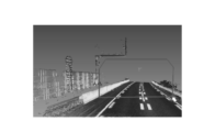
- FIG. 2 is a diagram showing an example of 3D point cloud information acquired by the 3D point cloud acquisition device according to the first embodiment. As shown in FIG. 2, by acquiring a three-dimensional point group that is positional information of a plurality of measurement points on and around the running surface, the outline of the running surface and surrounding structures can be grasped.
- the measurement vehicle 10 includes an attitude/position measuring device 12 that measures the attitude and position of the measurement vehicle 10 .
- the attitude/position measurement device 12 is, for example, an IMU (Inertial Measurement Unit).
- the posture information indicating the posture of the measurement vehicle 10 and the position information indicating the position of the measurement vehicle 10 measured by the posture/position measurement device 12 are transmitted to the trouble point candidate extraction device 30 .
- the attitude/position measuring device 12 may be configured to include a GPS (Global Positioning System) receiver and measure the position of the measurement vehicle 10 with the GPS receiver.
- GPS Global Positioning System
- the measurement vehicle 10 includes an imaging device 13 that captures images of the traveling surface and its surroundings.
- the imaging device 13 is, for example, a 4K camera.
- the image information captured by the imaging device 13 is transmitted to the trouble spot candidate extraction device 30 .
- the failure location candidate extraction device 30 includes a storage unit 31 .
- the storage unit 31 stores the three-dimensional point group information transmitted from the three-dimensional point group acquisition device 11 .
- the storage unit 31 stores posture information indicating the posture of the measurement vehicle 10 and position information indicating the position of the measurement vehicle 10 transmitted from the posture/position measuring device 12 .
- Image information transmitted from the imaging device 13 is stored in the storage unit 31 .
- the storage unit 31 stores information indicating the standard shape determined based on the construction gauge.
- the construction gauge is the range where the installation of structures is prohibited for the safety of traffic on the running surface on which vehicles pass, and the range is stipulated by law.
- a structure existing within the building gauge is also called a trouble spot. If trouble spots are found, they must be removed or marked to indicate that the structure is trouble spots.
- FIG. 3 is a diagram showing the relationship between the construction gauge and the running surface.
- FIG. 3 is a view of the road along the traveling direction of the measurement vehicle 10.
- the range of the construction gauge is determined by the height H1 from the running surface 2, the width W1 of the road, and the width W2 of the shoulder.
- the height H1 is 4.8m.
- the height of the standard shape 4 is defined by the height H1 of the construction gauge, and the width of the standard shape is defined by the width information stored in the storage unit 31.
- the outer shape of the construction gauge and the standard form match.
- the storage unit 31 stores information about roads on which the measurement vehicle 10 travels.
- 4 is a diagram showing an example of information about roads stored in a storage unit in Embodiment 1.
- FIG. The information about roads stored in the storage unit 31 includes, for example, the number of lanes for each section of the road, the width of the road, the width of the shoulder, and the like.
- the storage unit 31 also stores the width of the reference shape for each section of the road.
- the storage unit 31 stores the 3D point group information transmitted from the 3D point group acquisition device 11 of the measurement vehicle 10 .
- Image information transmitted from the imaging device 13 of the measurement vehicle 10 is stored in the storage unit 31 .
- the storage unit 31 stores the three-dimensional point group information and the image information described above in association with the position information acquired from the attitude/position measuring device 12 of the measurement vehicle 10 .
- the trouble spot candidate extraction device 30 includes an extraction unit 36 .
- the extraction unit 36 uses the three-dimensional point group information stored in the storage unit 31 to extract candidates for obstacle locations (problem location candidates) that are structures existing within the construction gauge.
- the extraction unit 36 compares the three-dimensional point cloud information with the reference form 4 over the route traveled by the measurement vehicle 10 . Then, the three-dimensional point group information that overlaps with the reference form 4 is extracted as a trouble point candidate.
- three-dimensional point group information that is a failure point candidate is indicated by a white triangle
- other three-dimensional point group information is indicated by a white circle.
- the extraction unit 36 determines the section of the road from the position information stored in the storage unit 31, and extracts the trouble spot candidate using the standard form 4 having a size corresponding to the section. For example, in section 1 shown in FIG. 4, a reference shape with a width of 6.5 m and a height of 4.8 m is used to extract trouble point candidates. Note that the extraction unit 36 extracts the trouble point candidate using a reference form whose size and inclination are changed according to the attitude of the measurement vehicle 10 and the section of the road, that is, the corrected reference form. will be described later.
- the trouble spot candidate extraction device 30 includes a specified value reception unit 32 .
- the designated value receiving unit 32 receives a designated value input by operating an input device (not shown).
- the designated value is, for example, a numerical value that designates the width of the canonical form 4 shown in FIG.
- the designated value receiving unit 32 transmits the received designated value to the storage unit 31 to update the width of the canonical form 4 in the designated section.
- the input device can be the display device 50 as the input device.
- a keyboard or the like may be provided as an input device.
- the specified value is not limited to the width of the standard shape 4, and may be, for example, the width of the road, the width of the shoulder, or the height of the standard shape.
- the width of the reference shape 4 is directly specified. is changed as a specified value, the width of the canonical form 4 can be changed.
- the trouble spot candidate extraction device 30 includes a reference form editing unit 33 .
- the canonical shape editing unit 33 transforms the shape of the canonical shape 4 stored in the storage unit 31 . Since the standard shape 4 can be transformed by inputting specified values, it is possible to set the standard shape 4 having a size suitable for the number of lanes, width, etc. of the road on which the measurement vehicle 10 travels. Further, the user of the failure point candidate extraction system 1 can arbitrarily change the size of the reference form by inputting a specified value.
- the trouble spot candidate extraction device 30 includes a gradient calculator 34 .
- the gradient calculation unit 34 acquires the attitude information indicating the attitude of the measurement vehicle 10 and the position information indicating the position of the measurement vehicle 10 transmitted from the attitude/position measuring device 12 of the measurement vehicle 10 .
- the gradient calculation unit 34 calculates the cross gradient of the traveling surface 2 on which the measurement vehicle 10 is traveling based on the acquired posture information.
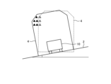
- FIG. 5 is a view of the road along the traveling direction of the measurement vehicle, showing the cross slope.
- the cross slope is the angle formed by the running surface 2 with the horizontal plane in the width direction of the road.
- the measurement vehicle 10 changes its attitude such that it also tilts under the influence of the cross slope of the running surface 2 . Therefore, the gradient calculation unit 34 calculates the cross gradient of the running surface 2 based on the acquired posture information of the measurement vehicle 10 .
- the inclination of the measurement vehicle 10 from the state of traveling on the horizontal plane is taken as the transverse gradient of the traveling surface 2 .
- the gradient calculator 34 calculates the cross gradient for each position of the measurement vehicle 10 indicated by the acquired position information.
- the calculated cross slope is stored in the storage unit 31 in association with the position of the measurement vehicle 10 .
- the slope calculator 34 calculates the cross slope of the running surface 2 from the three-dimensional point cloud data of the running surface 2 in that section.
- the gradient calculation unit 34 may calculate the cross gradient by estimating the change in the cross gradient in the section from the posture information before and after the section where the posture of the measurement vehicle 10 cannot be measured. For example, the gradient calculation unit 34 calculates the rate of change of the cross slope in the section from the posture information before and after the section in which the posture cannot be measured, and calculates the cross slope using the rate of change.
- the trouble spot candidate extraction device 30 includes a reference form adjustment unit 35 .
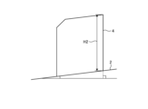
- the reference shape adjustment unit 35 inclines the reference shape 4 according to the cross slope of the running surface 2 calculated by the slope calculation unit 34 .
- a dashed line indicates the reference shape 4 when the running surface 2 is horizontal.
- the reference shape 4 tilted according to the cross slope is indicated by a solid line.
- the reference shape 4 must also be tilted, otherwise the extraction of the trouble point candidate will fail.
- the three-dimensional point cloud information indicated by the black triangles should be extracted as a candidate for the trouble point. It is outside the range and is not extracted as a trouble spot.
- the trouble spots are extracted using the reference form tilted according to the calculated cross gradient, the three-dimensional point cloud information indicated by the black triangles also overlaps the reference form 4, It is reliably extracted as a trouble point candidate.
- the cross slope of the running surface 2 is calculated using the posture information of the measurement vehicle 10 that inclines according to the cross slope of the running surface 2, so the cross slope can be calculated accurately.
- the attitude information measured by the attitude/position measuring device 12 of the measurement vehicle 10 is used, there is no need to bother to measure or input the cross gradient. Therefore, it is possible to reduce the time and effort required for extracting the trouble point candidates.
- the reference shape adjustment unit 35 changes the width of the reference shape 4 according to the change in the width of the road.
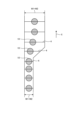
- FIG. 6 is a diagram showing an example in which the size of the reference shape changes according to changes in the width of the road.
- the running surface is viewed in plan.
- An arrow X indicates the traveling direction of the measurement vehicle 10 .
- the reference shape adjustment unit 35 acquires position information from the attitude/position measuring device 12 of the measurement vehicle 10 .
- the reference shape adjustment unit 35 determines the position along the travel direction of the measurement vehicle 10, that is, the section in which the measurement vehicle 10 is traveling, from the acquired position information.
- the reference shape adjusting unit 35 increases the width of the reference shape 4 when it is determined that the width W1+W2 of the road has increased through the determination of the section.
- the width of the reference shape 4 can be expanded.
- the reference shape adjusting unit 35 also narrows the width of the reference shape 4 when the width of the road becomes narrower. As a result, even if the width of the road changes, it is possible to reliably extract the trouble spot candidate.
- the width of the construction gauge may differ between when the vehicle passes through a platform and when it passes through a place without a platform. Even in such a case, by changing the width of the reference form 4, it is possible to more reliably extract the trouble point candidates.
- the reference shape adjustment unit 35 changes the position of the reference shape 4 along the width direction based on the position information of the measurement vehicle 10 and the position of the measurement vehicle 10 in the width direction of the road.
- FIG. 7 is a diagram for explaining movement of the measurement vehicle in the width direction, and is a diagram showing an example in which the position of the reference shape is not changed.
- FIG. 8 is a diagram for explaining movement of the measurement vehicle in the width direction, and is a diagram showing an example in which the position of the reference shape is changed by the reference shape adjustment unit. 7 and 8, the road is viewed from above.
- An arrow X indicates the traveling direction of the measurement vehicle.
- the position in the width direction of the reference shape 4 is the position in the width direction with respect to the measurement vehicle 10 . Therefore, moving the reference shape 4 in the width direction means moving the reference shape 4 relative to the measurement vehicle 10 .
- the measurement vehicle 10 does not advance linearly in the traveling direction, but advances while shifting in the width direction. At this time, if the reference shape 4 is moved along with the measurement vehicle 10, the reference shape may deviate from the width of the road as shown in FIG. If the reference form deviates from the width of the road, there may be cases where failure location candidates are not extracted.
- the positional information of the measurement vehicle 10 acquired from the attitude/position measurement device 12 of the measurement vehicle 10 is used to detect the displacement of the measurement vehicle 10 in the width direction, and as shown in FIG.
- the reference shape 4 By moving the reference shape 4 to the width of the road, the reference shape 4 is prevented from being deviated from the width of the road. As a result, even if the measurement vehicle 10 is displaced in the width direction, it is possible to reliably extract the trouble point candidates.
- the reference shape adjustment unit 35 determines the lane in which the measurement vehicle 10 is traveling from the position information of the measurement vehicle 10 .
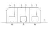
- FIG. 9 is a view of a road having multiple lanes along the traveling direction of the measurement vehicle. As shown in FIG. 9, the standard shapes 4a, 4b and 4c may be different for each of the lanes R1, R2 and R3 in accordance with the difference in the presence or absence of road shoulders for each of the lanes R1, R2 and R3. Even in such a case, the reference shape adjustment unit 35 determines the lane in which the measurement vehicle 10 is traveling based on the position information of the measurement vehicle 10, so that change the reference forms 4a, 4b, 4c. As a result, it is possible to extract obstacle location candidates using a reference shape that does not match the lane in which the vehicle is traveling, and to prevent the occurrence of omissions in the extraction of obstacle location candidates.
- the reference shape adjustment unit 35 may calculate the position of the measurement vehicle 10 by estimating the change in the position in the section from the position information before and after the section where the position of the measurement vehicle 10 cannot be measured. For example, the reference shape adjustment unit 35 calculates the rate of change in the position in that section from the position information before and after the section in which the position cannot be measured, and estimates the position of the measurement vehicle 10 using the rate of change.
- the standard shape adjustment unit 35 changes the orientation of the standard shape in the height direction according to the cross slope calculated by the slope calculation unit 34 .
- 10 and 11 are diagrams showing orientations in the height direction depending on the cross slope.
- the vertical direction is set to the vertical direction in the reference shape.
- the direction of the height direction in the standard shape is set to the direction perpendicular to the running surface 2 .
- the threshold is, for example, 2.5%. The threshold may be set differently for each section of the road. As a result, it becomes possible to extract the trouble point candidate with a reference form having an appropriate shape according to the cross slope.
- the trouble spot candidate extraction device 30 includes a height calculator 37 .
- the height calculator 37 calculates the height of the extracted trouble spot candidate from the running surface 2 .
- the height calculation unit calculates the height (minimum value) from the running surface 2 of the 3D point cloud information at the lowest position among the 3D point cloud information that is the trouble point candidate gathered in a certain range, and the lowest value.
- the height (maximum value) from the running surface 2 of the three-dimensional point cloud information at a high position is calculated.
- the trouble spot candidate extraction device 30 includes an output unit 38 .
- the output unit 38 causes the display device 50 to display information about the trouble spots extracted by the trouble spot candidate extraction device 30 .
- the display device 50 is, for example, a display such as a liquid crystal display.
- the output unit 38 causes the display device 50 to display the three-dimensional point group information that is the candidate for the failure location so as to be different from the other three-dimensional point group information.
- the three-dimensional point cloud information that is a candidate for the failure location may be displayed in a color different from that of the other three-dimensional point cloud information.
- the three-dimensional point group information may be superimposed or displayed side by side on the image information photographed by the imaging device 13 of the measurement vehicle 10 . Displaying the information superimposed on the image information may make it easier to determine whether or not the trouble point candidate is a structure that actually becomes a trouble point.
- the range of the reference form 4 indicating the building gauge is represented in the three-dimensional space by a polygon object or the like and displayed in a superimposed manner.
- the output unit 38 creates and outputs a form summarizing the information on the failure location candidates.
- 12 is a diagram showing an example of a form created by the output unit according to Embodiment 1.
- the form includes an ID (Identification) assigned to each extracted trouble point candidate, the position of the trouble point candidate, the cross slope of the place where the trouble point candidate was extracted, and the height of the trouble point candidate.
- a three-dimensional point cloud image in which the three-dimensional point cloud information as the trouble point candidate 5 is displayed differently from the other three-dimensional point cloud information.
- the output unit 38 outputs the form to the display device 50 to be displayed on the display device 50 or outputs to the printing device 70 to be printed by the printing device 70 .
- the printing device 70 is, for example, a printer such as a laser printer or an inkjet printer.
- the output unit 38 outputs information about the failure location candidate as an electronic file. For example, the output unit 38 outputs as an electronic file that can be edited with spreadsheet software or the like.
- FIG. 13 is a flowchart of a procedure for extracting trouble point candidates in the trouble point candidate extraction system according to the first embodiment.
- the width and the like of the reference form are stored in the storage unit 31 to define the reference form (step S1).
- the measurement vehicle 10 is caused to run on a road to acquire various types of information such as three-dimensional point group information, position information, posture information, and image information (step S2).
- the transverse gradient and the like are calculated from the acquired various information, and the reference form defined in step S1 is corrected (step S3).
- trouble spot candidates are extracted (step S4).
- a form is created and output to a display device or the like (step S5). Note that the definition of the reference form in step S1 may be performed after obtaining various information in step S2.
- the trouble point candidates may be extracted (step S4) and output to the display device (step S5).
- trouble spot candidates may be extracted in real time (step S4) and output to a display device or the like (step S5).
- FIG. 14 is a diagram showing an example of the hardware configuration of the trouble spot candidate extraction device according to the first embodiment.
- the trouble point candidate extraction device 30 can be realized by the processor 301 and the memory 302 shown in FIG.
- An example of the processor 301 is a CPU (Central Processing Unit, central processing unit, processing unit, arithmetic unit, microprocessor, microcomputer, processor, DSP (Digital Signal Processor)) or system LSI (Large Scale Integration).
- Examples of memory 302 are RAM (Random Access Memory) or ROM (Read Only Memory).
- the failure location candidate extraction device 30 is implemented by the processor 301 reading and executing a program for executing the operation of the failure location candidate extraction device 30 stored in the memory 302 . It can also be said that this program causes a computer to execute the procedure or method of the trouble point candidate extraction device 30 .
- the memory 302 is also used as temporary memory when the processor 301 executes various processes.
- the program executed by the processor 301 may be a computer program product having a computer-readable non-transitory recording medium containing a plurality of computer-executable instructions for performing data processing. .
- a program executed by the processor 301 causes the computer to execute a plurality of instructions to perform data processing.
- the trouble point candidate extraction device 30 may be realized by dedicated hardware. Also, the functions of the trouble spot candidate extraction device 30 may be partly realized by dedicated hardware and partly by software or firmware.
- the cross slope of the running surface 2 is calculated based on the posture information measured by the posture/position measuring device 12 mounted on the measurement vehicle 10. As in the case of calculating the cross slope based on the three-dimensional point cloud information of surface 2, errors due to noise are less likely to occur.
- the trouble point candidates are extracted only by causing the measurement vehicle 10 to travel on the road, the trouble point candidates can be easily extracted.
- the extraction device 30 may be mounted on the measurement vehicle 10 .
- the configuration shown in the above embodiment shows an example of the content of the present disclosure, and can be combined with another known technology. It is also possible to omit or change the part.
- R1, R2, R3 lanes 1 obstruction candidate extraction system, 2 running surface, 4, 4a, 4b, 4c reference form, 5 obstruction candidate, 10 measurement vehicle, 11 3D point cloud acquisition device, 12 posture/position measurement Device, 13 Imaging device, 30 Trouble spot candidate extraction device, 31 Storage unit, 32 Specified value reception unit, 33 Reference form editing unit, 34 Gradient calculation unit, 35 Reference form adjustment unit, 36 Extraction unit, 37 Height calculation unit, 38 output unit, 50 display device, 70 printer.
Landscapes
- Engineering & Computer Science (AREA)
- Mechanical Engineering (AREA)
- Train Traffic Observation, Control, And Security (AREA)
- Length Measuring Devices By Optical Means (AREA)
Abstract
支障箇所候補抽出装置(30)は、建築限界に基づいて定められる基準形が記憶された記憶部(31)と、計測車両(10)から取得した計測車両(10)の姿勢を示す姿勢情報に基づいて走行面の横断勾配を算出する勾配算出部(34)と、横断勾配に基づいて基準形を傾ける基準形調整部(35)と、計測車両(10)から取得した走行面およびその周囲の複数の測定点の位置情報である3次元点群情報のうち、基準形と重なる3次元点群情報を支障箇所として抽出する抽出部(36)と、を備える。
Description
本開示は、建築限界の範囲内に存在する支障箇所の候補である支障箇所候補を抽出する支障箇所候補抽出装置、支障箇所候補抽出方法、支障箇所候補抽出プログラム、および支障箇所候補抽出システムに関するものである。
車両が通行する道路の走行面上には、通行の安全のために構造物の設置を禁止する範囲が法令で設定されている。法令では、構造物の設置が禁止される範囲が建築限界として定められている。車両は、例えば自動車、鉄道車両である。走行面は、車両が自動車であれば道路面であり、車両が鉄道車両であれば線路の天面である。建築限界は、例えば道路であれば、道路面からの高さおよび車道と路肩の幅で定義される。また、建築限界の範囲内に存在する構造物は支障箇所とも呼ばれる。
支障箇所を取り除くためには支障箇所がどこに存在しているかを把握する必要がある。そのため、道路を走行する車両から得られた3次元点群情報を用いて支障箇所となる候補(支障箇所候補)を自動で抽出することが行われている。このとき、3次元点群情報に対して建築限界に基づいて基準形が定義され、この基準形に重なる3次元点群情報が支障箇所候補として抽出される。
走行面は常に水平ではなく左右の傾き、すなわち横断勾配がある。建築限界も走行面の横断勾配に合わせて傾かせる必要がある。特許文献1には、車両が鉄道車両であって走行面が線路の天面である場合に、線路のカントを用いて走行面の傾きに応じた基準形を定義することで、支障箇所候補を確実に算出する技術が開示されている。走行面が道路面である場合であれば、走行面の3次元点群情報を用いて横断勾配を算出し、算出された横断勾配に応じて基準形を傾かせることで、横断勾配のある箇所でも支障箇所候補を抽出することができる。
しかしながら、3次元点群情報に含まれるノイズの影響で、算出された横断勾配に誤差が生じる場合がある。また、3次元点群情報の計測誤差の影響で、算出された横断勾配に誤差が生じる場合がある。算出された横断勾配に誤差が生じると、基準形の傾きにも誤差が生じるため、支障箇所候補を正確に抽出することができない。
本開示は、上記に鑑みてなされたものであって、より正確に走行面の横断勾配を算出し、より正確に支障箇所候補を抽出することができる支障箇所候補抽出装置を得ることを目的とする。
上述した課題を解決し、目的を達成するために、本開示は、車両の走行面を基準に定められる建築限界の範囲内にある支障箇所候補を抽出する支障箇所候補抽出装置である。支障箇所候補抽出装置は、建築限界に基づいて定められる基準形が記憶された基準形記憶部と、車両から取得した車両の姿勢を示す姿勢情報に基づいて走行面の横断勾配を算出する勾配算出部と、横断勾配に基づいて基準形を傾ける基準形調整部と、車両から取得した走行面およびその周囲の複数の測定点の位置情報である3次元点群情報のうち、基準形と重なる3次元点群情報を支障箇所候補として抽出する抽出部と、を備える。
本開示によれば、より正確に走行面の横断勾配を算出し、より正確に支障箇所候補を抽出することができる支障箇所候補抽出装置を得ることができる、という効果を奏する。
以下に、本開示の実施の形態にかかる支障箇所候補抽出装置、支障箇所候補抽出方法、支障箇所候補抽出プログラム、および支障箇所候補抽出システムを図面に基づいて詳細に説明する。
実施の形態1.
図1は、実施の形態1にかかる支障箇所候補抽出システムの機能構成を示す図である。支障箇所候補抽出システム1は、計測車両10と支障箇所候補抽出装置30を備える。支障箇所候補抽出システム1には、表示装置50と印刷装置70とが接続されている。
図1は、実施の形態1にかかる支障箇所候補抽出システムの機能構成を示す図である。支障箇所候補抽出システム1は、計測車両10と支障箇所候補抽出装置30を備える。支障箇所候補抽出システム1には、表示装置50と印刷装置70とが接続されている。
まず、計測車両10について説明する。計測車両10は、走行面を走行する車両である。計測車両10は、例えば自動車である。計測車両10が自動車であれば、走行する場所は道路であり、走行面は道路面である。
計測車両10は、例えば鉄道車両である。計測車両10が鉄道車両であれば、走行する場所は線路であり、走行面は線路の天面である。なお、以下の説明では、計測車両10が自動車である例を挙げて説明する。
計測車両10は、走行面を走行しながら走行面および周囲の形状を3次元点群情報として収集する。計測車両10は、3次元点群情報を取得する3次元点群取得装置11を備える。3次元点群取得装置11は、例えばレーザスキャナである。3次元点群取得装置11によって取得された3次元点群情報は、支障箇所候補抽出装置30に向けて送信される。
図2は、実施の形態1における3次元点群取得装置によって取得された3次元点群情報の一例を示す図である。図2に示すように、走行面およびその周囲の複数の測定点の位置情報である3次元点群が取得されることで、走行面およびその周囲の構造物の外形が把握される。
図1に戻って、計測車両10は、計測車両10の姿勢および位置を計測する姿勢・位置計測装置12を備える。姿勢・位置計測装置12は、例えばIMU(慣性計測装置:Inertial Measurement Unit)である。姿勢・位置計測装置12によって計測された計測車両10の姿勢を示す姿勢情報と計測車両10の位置を示す位置情報は、支障箇所候補抽出装置30に向けて送信される。なお、姿勢・位置計測装置12がGPS(Grobal Positioning System)レシーバを備えて、GPSレシーバによって計測車両10の位置を計測するように構成されていてもよい。
計測車両10は、走行面およびその周囲の画像を撮影する撮像装置13を備える。撮像装置13は、例えば4Kカメラである。撮像装置13によって撮影された画像情報は、支障箇所候補抽出装置30に向けて送信される。
次に、支障箇所候補抽出装置30について説明する。支障箇所候補抽出装置30は、記憶部31を備える。記憶部31には、3次元点群取得装置11から送信された3次元点群情報が記憶される。記憶部31には、姿勢・位置計測装置12から送信された計測車両10の姿勢を示す姿勢情報と計測車両10の位置を示す位置情報とが記憶される。記憶部31には、撮像装置13から送信された画像情報が記憶される。
記憶部31には、建築限界に基づいて定められた基準形を示す情報が記憶される。建築限界とは、車両が通行する走行面上で通行の安全のために構造物の設置が禁止された範囲であり、その範囲は法令で定められている。また、建築限界の範囲内に存在する構造物は支障箇所とも呼ばれる。支障箇所が発見された場合には、それらを取り除いたり、その構造物が支障箇所であることを示す表示を付したりする必要がある。
基準形は、建築限界に基づいて規定される。図3は、建築限界と走行面との関係を示す図である。図3は、計測車両10の進行方向に沿って道路を見た図となっている。建築限界の範囲は、走行面2からの高さH1と、道路の幅W1と、路肩の幅W2によって定められる。例えば、高さH1は4.8mである。本実施の形態1では、基準形4の高さは建築限界の高さH1で定義され、基準形の幅は記憶部31に記憶された幅情報で定義されているものとする。なお、図3で示す例では建築限界の外形と基準形とが一致している。
記憶部31には、計測車両10が走行する道路に関する情報が記憶されている。図4は、実施の形態1において記憶部に記憶された道路に関する情報の一例を示す図である。記憶部31に記憶されている道路に関する情報は、例えば、道路の区間ごとの車線数、道路の幅、路肩の幅などである。また、記憶部31には、道路の区間ごとに基準形の幅が記憶されている。
記憶部31には、計測車両10の3次元点群取得装置11から送信された3次元点群情報が記憶される。また、記憶部31には、計測車両10の撮像装置13から送信された画像情報が記憶される。記憶部31には、上述した3次元点群情報と画像情報とが、計測車両10の姿勢・位置計測装置12から取得した位置情報と紐づけて記憶される。
支障箇所候補抽出装置30は、抽出部36を備える。抽出部36は、記憶部31に記憶された3次元点群情報を用いて、建築限界の範囲内に存在する構造物である支障箇所の候補(支障箇所候補)を抽出する。
具体的には、抽出部36は、計測車両10が走行した経路にわたって、3次元点群情報と基準形4とを比較する。そして、基準形4と重なる3次元点群情報を支障箇所候補として抽出する。図3では、支障箇所候補となる3次元点群情報を白抜きの三角形で示し、それ以外の3次元点群情報を白抜きの丸で示している。抽出部36は、記憶部31に記憶された位置情報から道路の区間を判別し、その区間に応じた大きさの基準形4を用いて支障箇所候補を抽出する。例えば、図4に示す区間1では、幅が6.5m、高さが4.8mの基準形を用いて支障箇所候補の抽出が行われる。なお、抽出部36は、計測車両10の姿勢および道路の区間等に応じて大きさおよび傾きを変化させた基準形、すなわち補正された基準形を用いて支障箇所候補を抽出するが、その詳細については後述する。
支障箇所候補抽出装置30は、指定値受付部32を備える。指定値受付部32は、図示を省略した入力装置が操作されて入力された指定値を受け付ける。指定値は、例えば、図4で示した基準形4の幅を指定する数値である。指定値受付部32は、受け付けた指定値を記憶部31に送信して、指定された区間の基準形4の幅を更新させる。すなわち、本実施の形態1では、区間ごとに異なる幅の基準形を規定および変更することが可能となっている。また、入力装置は、後述する表示装置50がタッチパネルであれば、表示装置50を入力装置とすることができる。また、キーボード等を入力装置として設けてもよい。
なお、指定値は基準形4の幅に限られず、例えば、道路の幅、路肩の幅、または基準形の高さであってもよい。本実施の形態1では、基準形4の幅を直接指定する構成としているが、道路の幅および路肩の幅から基準形4の幅が決められる構成の場合には、道路の幅および路肩の幅を指定値として変更することで、基準形4の幅を変更することが可能となる。
支障箇所候補抽出装置30は、基準形編集部33を備える。基準形編集部33は、記憶部31に記憶された基準形4の幅が更新されると、記憶部31に記憶された基準形4の形状を変形させる。指定値の入力によって基準形4を変形できるので、計測車両10が走行した道路の車線数、幅等に適した大きさの基準形4を設定することができる。また、支障箇所候補抽出システム1の使用者は、指定値を入力することで基準形の大きさを任意に変更することができる。
支障箇所候補抽出装置30は、勾配算出部34を備える。勾配算出部34は、計測車両10の姿勢・位置計測装置12から送信された計測車両10の姿勢を示す姿勢情報と計測車両10の位置を示す位置情報を取得する。
勾配算出部34は、取得した姿勢情報に基づいて計測車両10が走行している走行面2の横断勾配を算出する。図5は、計測車両の進行方向に沿って道路を見た図であって、横断勾配を示す図である。横断勾配は、道路の幅方向において走行面2が水平面となす角度である。図5に示すように、計測車両10は、走行面2の横断勾配の影響で自身も傾斜するように姿勢が変化する。そこで、勾配算出部34は、取得した計測車両10の姿勢情報に基づいて、走行面2の横断勾配を算出する。具体的には、水平面を走行している状態からの計測車両10の傾きを走行面2の横断勾配とする。勾配算出部34は、取得した位置情報が示す計測車両10の位置ごとに横断勾配を算出する。算出された横断勾配は、計測車両10の位置に紐づけて記憶部31に記憶される。
計測車両10の姿勢・位置計測装置12が取得した姿勢情報には、計測エラー等によって計測車両10の姿勢を計測できていない区間が存在する場合がある。勾配算出部34は、その区間における走行面2の3次元点群データから走行面2の横断勾配を算出する。なお、勾配算出部34は、計測車両10の姿勢を計測できていない区間の前後の姿勢情報から、その区間での横断勾配の変化を推測して、横断勾配を算出してもよい。例えば、勾配算出部34は、姿勢を計測できていない区間の前後の姿勢情報から、その区間での横断勾配の変化率を算出し、その変化率を用いて横断勾配を算出する。
支障箇所候補抽出装置30は、基準形調整部35を備える。基準形調整部35は、勾配算出部34によって算出された走行面2の横断勾配に応じて基準形4を傾かせる。図5では、走行面2が水平である場合の基準形4が破線で示されている。また、横断勾配に応じて傾けられた基準形4が実線で示されている。
走行面2に横断勾配がある場合には、建築限界も横断勾配に合わせて傾かせて支障箇所を判別する必要がある。したがって、走行面2に横断勾配がある場合には基準形4も傾かせなければ、支障箇所候補の抽出に漏れが生じてしまう。図5に示すように、黒塗りの三角形で示した3次元点群情報は、本来は支障箇所候補として抽出されなければならないが、基準形を傾かせない場合には破線で示した基準形の範囲外となり、支障箇所として抽出されない。本実施の形態1では、算出された横断勾配に応じて傾かせた基準形を用いて支障箇所が抽出されるので、黒塗りの三角形で示した3次元点群情報も基準形4と重なり、支障箇所候補として確実に抽出される。
本実施の形態1では、走行面2の横断勾配に応じて傾斜する計測車両10の姿勢情報を用いて走行面2の横断勾配を算出しているので、正確に横断勾配を算出することができる。また、計測車両10の姿勢・位置計測装置12に計測された姿勢情報を用いているので、わざわざ横断勾配を計測したり、入力したりする必要がない。そのため、支障箇所候補の抽出にかかる時間や手間の削減を図ることができる。
基準形調整部35は、道路の幅の変化に応じて基準形4の幅を変化させる。図6は、道路の幅の変化に応じて基準形の大きさが変化する例を示す図である。図6では、走行面を平面視している。矢印Xは、計測車両10の進行方向を示している。基準形調整部35は、計測車両10の姿勢・位置計測装置12から位置情報を取得する。基準形調整部35は、取得した位置情報から、計測車両10の進行方向に沿った位置、すなわち走行している区間を判別する。基準形調整部35は、区間の判別によって道路の幅W1+W2が広くなったことを判別した場合には、基準形4の幅を大きくする。例えば、計測車両10の走行している区間が、図4に示した区間1から区間2に変化した場合には、記憶部31に記憶された情報を参照して、その区間で指定された基準形の幅に変化させることで、基準形4の幅を広げることができる。もちろん、基準形調整部35は、道路の幅が狭くなった場合には、基準形4の幅も狭くする。これにより、道路の幅が変化しても支障箇所候補を確実に抽出することが可能となる。計測車両10が鉄道車両の場合には、ホームを通過する場合と、ホームのない場所を通過する場合とで建築限界の幅が異なる場合がある。このような場合であっても、基準形4の幅を変化させることで、より確実に支障箇所候補の抽出を行うことができる。
基準形調整部35は、計測車両10の位置情報から、道路の幅方向における計測車両10の位置に基づいて、基準形4の幅方向に沿った位置を変更する。図7は、計測車両の幅方向への移動を説明する図であり、基準形の位置の変更が行われない例を示す図である。図8は、計測車両の幅方向への移動を説明する図であり、基準形調整部によって基準形の位置の変更が行われる例を示す図である。図7および図8では、道路を平面視している。矢印Xは計測車両の進行方向を示している。なお、本実施の形態1において、基準形4の幅方向への位置とは計測車両10を基準とした幅方向の位置とする。したがって、基準形4を幅方向へ移動するとは、計測車両10に対して相対的に基準形4を移動することをいう。
図7および図8に示すように、計測車両10は進行方向に向けて直線的に進むわけではなく、幅方向にずれながら進んでいく。このとき、計測車両10に合わせて基準形4も移動させていくと、図7に示すように、道路の幅から基準形が外れてしまう場合がある。基準形が道路の幅から外れてしまうと、支障箇所候補の抽出に漏れが生じてしまう場合がある。
一方、本実施の形態1では、計測車両10の姿勢・位置計測装置12から取得した計測車両10の位置情報を用いて、計測車両10の幅方向へのずれを検出し、図8に示すように基準形4を移動させることで、道路の幅から基準形4が外れないようにする。これにより、計測車両10が幅方向にずれた場合であっても、確実に支障箇所候補を抽出することができる。
基準形調整部35は、計測車両10の位置情報から、計測車両10が走行している車線を判別する。図9は、計測車両の進行方向に沿って複数の車線を有する道路を見た図である。図9に示すように、車線R1,R2,R3ごとの路肩の有無等の違いに合わせて、車線R1,R2,R3ごとに基準形4a,4b,4cを異ならせる場合がある。このような場合であっても、基準形調整部35が、計測車両10の位置情報から計測車両10が走行している車線を判別することで、走行している車線R1,R2,R3に合わせた基準形4a,4b,4cを変更する。これにより、走行している車線に合っていない基準形を用いて支障箇所候補の抽出ができ、支障箇所候補の抽出に漏れが生じてしまうことを防ぐことができる。
計測車両10の姿勢・位置計測装置12が取得した位置情報には、計測エラー等によって計測車両10の位置を計測できていない区間が存在する場合がある。基準形調整部35は、計測車両10の位置を計測できていない区間の前後の位置情報から、その区間での位置の変化を推測して、計測車両10の位置を算出してもよい。例えば、基準形調整部35は、位置を計測できていない区間の前後の位置情報から、その区間での位置の変化率を算出し、その変化率を用いて計測車両10の位置を推測する。
基準形調整部35は、勾配算出部34によって算出された横断勾配に応じて、基準形における高さ方向の向きを異ならせる。図10および図11は、横断勾配に応じた高さ方向の向きを示す図である。図10に示すように、横断勾配が閾値以下の場合には、鉛直方向を基準形における高さ方向の向きを鉛直方向とする。また、図11に示すように、横断勾配が閾値を超える場合には、基準形における高さ方向の向きを走行面2と垂直な方向とする。閾値は、例えば、2.5%である。閾値は、道路の区間ごとに異ならせて設定されていてもよい。これにより、横断勾配に応じて適切な形状の基準形で支障箇所候補を抽出することが可能となる。
支障箇所候補抽出装置30は、高さ算出部37を備える。高さ算出部37は、抽出された支障箇所候補の走行面2からの高さを算出する。高さ算出部は、一定の範囲に集まった支障箇所候補となる3次元点群情報のうち、最も低い位置にある3次元点群情報の走行面2からの高さ(最低値)と、最も高い位置にある3次元点群情報の走行面2からの高さ(最高値)を算出する。
支障箇所候補抽出装置30は、出力部38を備える。出力部38は、支障箇所候補抽出装置30によって抽出された支障箇所に関する情報を表示装置50に表示させる。表示装置50は例えば液晶ディスプレイなどのディスプレイである。ここで、表示装置50は支障箇所候補抽出システム1とは別に設けた例を示しているが、例えば、表示装置50が支障箇所候補抽出装置30の一部であってもよい。出力部38は、図3に示すように、支障箇所候補となる3次元点群情報を他の3次元点群情報と異ならせて表示装置50に表示させる。例えば、支障箇所候補となる3次元点群情報を他の3次元点群情報と異なる色で表示させてもよい。ここで、計測車両10の撮像装置13によって撮影された画像情報に3次元点群情報を重ねて表示または並べて表示させてもよい。画像情報と重ねて表示することで、支障箇所候補が、実際に支障箇所となる構造物であるか否かの判別がしやすくなる場合がある。また、支障箇所候補5となる3次元点群情報を表示装置50に表示する際に、建築限界を示す基準形4の範囲を3次元空間上にポリゴン・オブジェクトなどで表して重畳して表示してもよい。
また、出力部38は、支障箇所候補に関する情報をまとめた帳票を作成して出力する。図12は、実施の形態1における出力部によって作成された帳票の一例を示す図である。図12に示すように、帳票には抽出された支障箇所候補ごとに付与されたID(Idintification)、支障箇所候補の位置、支障箇所候補が抽出された場所の横断勾配、支障箇所候補の高さ、支障箇所候補5となる3次元点群情報が他の3次元点群情報と異ならせて表示された3次元点群画像が掲載される。出力部38は、帳票を表示装置50に出力して表示装置50に表示させたり、印刷装置70に出力して印刷装置70に印刷させたりする。印刷装置70は例えばレーザプリンタ、インクジェットプリンタなどのプリンタである。また、支障箇所候補5となる3次元点群情報を帳票に掲載する際に、建築限界を示す基準形4の範囲を3次元空間上にポリゴン・オブジェクトなどで表して重畳して掲載してもよい。また、出力部38は、支障箇所候補に関する情報を電子ファイルとして出力する。例えば、出力部38は、表計算ソフトなどで編集可能な電子ファイルとして出力する。
次に、支障箇所候補抽出システム1における支障箇所候補の抽出手順について説明する。図13は、実施の形態1にかかる支障箇所候補抽出システムにおける支障箇所候補の抽出手順を示すフローチャートである。
まず、記憶部31に基準形の幅等が記憶されて基準形が定義される(ステップS1)。次に、計測車両10に道路を走行させて、3次元点群情報、位置情報、姿勢情報、画像情報といった各種情報を取得する(ステップS2)。次に、取得した各種情報から横断勾配等が算出されてステップS1で定義された基準形の補正が行われる(ステップS3)。次に、補正された基準形を用いて支障箇所候補の抽出が行われる(ステップS4)。次に、抽出された支障箇所候補に基づいて帳票の作成、表示装置等への出力が行われる(ステップS5)。なお、ステップS1の基準形の定義は、ステップS2の各種情報の取得の後に行われても構わない。なお、計測車両10が道路を走行して各種情報を取得してから、まとめて支障箇所候補の抽出(ステップS4)および表示装置等への出力(ステップS5)を行わせてもよいし、計測車両10の走行中に取得した各種情報からリアルタイムで支障箇所候補の抽出(ステップS4)および表示装置等への出力(ステップS5)を行わせてもよい。
図14は、実施の形態1にかかる支障箇所候補抽出装置のハードウェア構成の一例を示す図である。支障箇所候補抽出装置30は、図14に示したプロセッサ301およびメモリ302により実現することができる。プロセッサ301の例は、CPU(Central Processing Unit、中央処理装置、処理装置、演算装置、マイクロプロセッサ、マイクロコンピュータ、プロセッサ、DSP(Digital Signal Processor)ともいう)またはシステムLSI(Large Scale Integration)である。メモリ302の例は、RAM(Random Access Memory)またはROM(Read Only Memory)である。
支障箇所候補抽出装置30は、プロセッサ301が、メモリ302で記憶されている、支障箇所候補抽出装置30の動作を実行するためのプログラムを読み出して実行することにより実現される。また、このプログラムは、支障箇所候補抽出装置30の手順または方法をコンピュータに実行させるものであるともいえる。メモリ302は、プロセッサ301が各種処理を実行する際の一時メモリにも使用される。
プロセッサ301が実行するプログラムは、コンピュータで実行可能な、データ処理を行うための複数の命令を含むコンピュータ読取り可能かつ非遷移的な(non-transitory)記録媒体を有するコンピュータプログラムプロダクトであってもよい。プロセッサ301が実行するプログラムは、複数の命令がデータ処理を行うことをコンピュータに実行させる。
また、支障箇所候補抽出装置30を専用のハードウェアで実現してもよい。また、支障箇所候補抽出装置30の機能について、一部を専用のハードウェアで実現し、一部をソフトウェアまたはファームウェアで実現するようにしてもよい。
以上説明した支障箇所候補抽出システム1によれば、計測車両10に搭載された姿勢・位置計測装置12によって計測された姿勢情報に基づいて、走行面2の横断勾配を算出しているので、走行面2の3次元点群情報に基づいて横断勾配を算出する場合のように、ノイズによって誤差が生じにくい。
そのため、より正確に算出された横断勾配に応じて基準形を傾かせて、より正確に支障箇所候補を抽出することができる。また、計測車両10に道路を走行させるだけで支障箇所候補が抽出されるので、容易に支障箇所候補を抽出することができる。
なお、本実施の形態1では、支障箇所候補抽出装置30が計測車両10とは異なる場所にある場合、例えばサーバ側に設けられているような場合を例に挙げて説明したが、支障箇所候補抽出装置30が計測車両10に搭載されていてもよい。
以上の実施の形態に示した構成は、本開示の内容の一例を示すものであり、別の公知の技術と組み合わせることも可能であるし、本開示の要旨を逸脱しない範囲で、構成の一部を省略、変更することも可能である。
R1,R2,R3 車線、1 支障箇所候補抽出システム、2 走行面、4,4a,4b,4c 基準形、5 支障箇所候補、10 計測車両、11 3次元点群取得装置、12 姿勢・位置計測装置、13 撮像装置、30 支障箇所候補抽出装置、31 記憶部、32 指定値受付部、33 基準形編集部、34 勾配算出部、35 基準形調整部、36 抽出部、37 高さ算出部、38 出力部、50 表示装置、70 印刷装置。
Claims (14)
- 車両の走行面を基準に定められる建築限界の範囲内にある支障箇所候補を抽出する支障箇所候補抽出装置であって、
前記建築限界に基づいて定められる基準形が記憶された基準形記憶部と、
前記車両から取得した前記車両の姿勢を示す姿勢情報に基づいて前記走行面の横断勾配を算出する勾配算出部と、
前記横断勾配に基づいて前記基準形を傾ける基準形調整部と、
前記車両から取得した前記走行面およびその周囲の複数の測定点の位置情報である3次元点群情報のうち、前記基準形と重なる前記3次元点群情報を前記支障箇所候補として抽出する抽出部と、を備えることを特徴とする支障箇所候補抽出装置。 - 前記基準形の前記走行面からの高さの指定値および前記基準形の幅の指定値の入力を受け付ける指定値受付部と、
前記指定値に基づいて前記記憶部に記憶された前記基準形を変形させる基準形編集部と、をさらに備えることを特徴とする請求項1に記載の支障箇所候補抽出装置。 - 前記基準形調整部は、前記車両から取得した前記車両の位置情報に基づいて前記基準形の幅方向に沿った位置を変更することを特徴とする請求項1または2に記載の支障箇所候補抽出装置。
- 前記基準形記憶部には、前記車両の進行方向に沿った位置に対応して異ならせた複数の前記基準形が記憶されており、
前記抽出部は、前記車両から取得した前記車両の位置情報に基づいて前記車両の進行方向に沿った位置に対応する前記基準形を用いて前記支障箇所候補を抽出することを特徴とする請求項1から3のいずれか1つに記載の支障箇所候補抽出装置。 - 前記車両から取得した前記車両の位置情報に基づいて前記車両が走行している車線を判別する車線判別部をさらに備え、
前記基準形記憶部には、前記車線に対応して異ならせた複数の前記基準形が記憶されており、
前記抽出部は、前記車線判別部に判別された前記車線に対応する前記基準形を用いて前記支障箇所候補を抽出することを特徴とする請求項1から4のいずれか1つに記載の支障箇所候補抽出装置。 - 前記勾配算出部は、前記姿勢情報が取得できていない区間では、その前後の前記姿勢情報を用いて前記横断勾配を算出することを特徴とする請求項1から5のいずれか1つに記載の支障箇所候補抽出装置。
- 前記勾配算出部は、前記姿勢情報が取得できていない区間では、その前後の前記3次元点群情報を用いて前記横断勾配を算出することを特徴とする請求項1から5のいずれか1つに記載の支障箇所候補抽出装置。
- 前記支障箇所候補となる前記3次元点群情報を、他の前記3次元点群情報と異ならせて表示させる出力部をさらに備えることを特徴とする請求項1から7のいずれか1つに記載の支障箇所候補抽出装置。
- 前記支障箇所候補の前記走行面からの高さを算出する高さ算出部をさらに備え、
前記出力部は、前記高さ算出部によって算出された高さを表示させることを特徴とする請求項8に記載の支障箇所候補抽出装置。 - 前記基準形調整部は、前記横断勾配の大きさに応じて、前記基準形における高さ方向の向きを異ならせることを特徴とする請求項1から9のいずれか1つに記載の支障箇所候補抽出装置。
- 前記基準形調整部は、前記横断勾配が閾値以下の場合には鉛直方向を前記基準形における高さ方向の向きとし、前記横断勾配が前記閾値を超える場合には前記走行面に垂直な方向を前記基準形における高さ方向の向きとすることを特徴とする請求項10に記載の支障箇所候補抽出装置。
- 車両の走行面を基準に定められる建築限界の範囲内にある支障箇所候補を抽出する支障箇所候補抽出方法であって、
前記建築限界に基づいて定められる基準形を定義するステップと、
前記車両から取得した前記車両の姿勢を示す姿勢情報に基づいて前記走行面の横断勾配を算出するステップと、
前記横断勾配に基づいて前記基準形を傾けるステップと、
前記車両から取得した前記走行面およびその周囲の複数の測定点の位置情報である3次元点群情報のうち、前記基準形と重なる前記3次元点群情報を前記支障箇所候補として抽出するステップと、を備えることを特徴とする支障箇所候補抽出方法。 - 車両の走行面を基準に定められる建築限界の範囲内にある支障箇所を抽出する支障箇所候補抽出プログラムであって、
前記建築限界に基づいて定められる基準形を定義するステップと、
前記車両から取得した前記車両の姿勢を示す姿勢情報に基づいて前記走行面の横断勾配を算出するステップと、
前記横断勾配に基づいて前記基準形を傾けるステップと、
前記車両から取得した前記走行面およびその周囲の複数の測定点の位置情報である3次元点群情報のうち、前記基準形と重なる前記3次元点群情報を前記支障箇所候補として抽出するステップと、をコンピュータに実行させることを特徴とする支障箇所候補抽出プログラム。 - 車両に搭載されて走行面と周囲の複数の測定点の位置情報である3次元点群情報を取得する3次元点群取得装置と、
前記車両の姿勢を検出する姿勢検出装置と、
前記走行面を基準に定められる建築限界に基づいて定められる基準形が記憶された基準形記憶部と、
前記車両から取得した前記車両の姿勢を示す姿勢情報に基づいて前記走行面の横断勾配を算出する勾配算出部と、
前記横断勾配に基づいて前記基準形を傾ける基準形調整部と、
前記3次元点群情報のうち、前記基準形と重なる前記3次元点群情報を前記建築限界の範囲内にある支障箇所候補として抽出する抽出部と、を備えることを特徴とする支障箇所候補抽出システム。
Priority Applications (2)
| Application Number | Priority Date | Filing Date | Title |
|---|---|---|---|
| JP2022525494A JP7162779B1 (ja) | 2021-11-30 | 2021-11-30 | 支障箇所候補抽出装置、支障箇所候補抽出方法、支障箇所候補抽出プログラム、および支障箇所候補抽出システム |
| PCT/JP2021/043943 WO2023100263A1 (ja) | 2021-11-30 | 2021-11-30 | 支障箇所候補抽出装置、支障箇所候補抽出方法、支障箇所候補抽出プログラム、および支障箇所候補抽出システム |
Applications Claiming Priority (1)
| Application Number | Priority Date | Filing Date | Title |
|---|---|---|---|
| PCT/JP2021/043943 WO2023100263A1 (ja) | 2021-11-30 | 2021-11-30 | 支障箇所候補抽出装置、支障箇所候補抽出方法、支障箇所候補抽出プログラム、および支障箇所候補抽出システム |
Publications (1)
| Publication Number | Publication Date |
|---|---|
| WO2023100263A1 true WO2023100263A1 (ja) | 2023-06-08 |
Family
ID=83806063
Family Applications (1)
| Application Number | Title | Priority Date | Filing Date |
|---|---|---|---|
| PCT/JP2021/043943 Ceased WO2023100263A1 (ja) | 2021-11-30 | 2021-11-30 | 支障箇所候補抽出装置、支障箇所候補抽出方法、支障箇所候補抽出プログラム、および支障箇所候補抽出システム |
Country Status (2)
| Country | Link |
|---|---|
| JP (1) | JP7162779B1 (ja) |
| WO (1) | WO2023100263A1 (ja) |
Citations (3)
| Publication number | Priority date | Publication date | Assignee | Title |
|---|---|---|---|---|
| JP2005271717A (ja) * | 2004-03-24 | 2005-10-06 | East Japan Railway Co | 鉄道建築限界判別プログラム |
| JP2016000598A (ja) * | 2014-06-12 | 2016-01-07 | 西日本旅客鉄道株式会社 | 線路空間支障物検知システム |
| JP2017019388A (ja) * | 2015-07-10 | 2017-01-26 | 西日本旅客鉄道株式会社 | レーザ点群を用いた建築限界内点群判定システム及びレーザ点群を用いた建築限界内点群判定方法並びにレーザ点群を用いた建築限界内点群判定プログラム |
-
2021
- 2021-11-30 JP JP2022525494A patent/JP7162779B1/ja active Active
- 2021-11-30 WO PCT/JP2021/043943 patent/WO2023100263A1/ja not_active Ceased
Patent Citations (3)
| Publication number | Priority date | Publication date | Assignee | Title |
|---|---|---|---|---|
| JP2005271717A (ja) * | 2004-03-24 | 2005-10-06 | East Japan Railway Co | 鉄道建築限界判別プログラム |
| JP2016000598A (ja) * | 2014-06-12 | 2016-01-07 | 西日本旅客鉄道株式会社 | 線路空間支障物検知システム |
| JP2017019388A (ja) * | 2015-07-10 | 2017-01-26 | 西日本旅客鉄道株式会社 | レーザ点群を用いた建築限界内点群判定システム及びレーザ点群を用いた建築限界内点群判定方法並びにレーザ点群を用いた建築限界内点群判定プログラム |
Also Published As
| Publication number | Publication date |
|---|---|
| JP7162779B1 (ja) | 2022-10-28 |
| JPWO2023100263A1 (ja) | 2023-06-08 |
Similar Documents
| Publication | Publication Date | Title |
|---|---|---|
| JP6658088B2 (ja) | 情報処理装置、プログラム、及び地図データ更新システム | |
| CN104240536B (zh) | 一种用于检测车行道上的车辆的车道位置的装置及方法 | |
| US8824741B2 (en) | Method for estimating the roll angle in a travelling vehicle | |
| JP7020348B2 (ja) | 自車位置推定装置 | |
| KR100921427B1 (ko) | 영상 기반 내비게이션을 위한 가상차선을 생성하는 방법 및그 장치 | |
| JP5716443B2 (ja) | 車線境界検出装置及び車線境界検出方法 | |
| EP2372304A2 (en) | Vehicle position recognition system | |
| JP5088401B2 (ja) | 道路構造測定方法および道路面測定装置 | |
| CN102227758A (zh) | 摄像装置 | |
| JP2018092483A (ja) | 物体認識装置 | |
| CN104204726A (zh) | 移动物体位置姿态估计装置和移动物体位置姿态估计方法 | |
| KR20060087449A (ko) | 차량 위치 인식 장치 및 차량 위치 인식 방법 | |
| JP6543983B2 (ja) | 道路情報生成装置及びプログラム | |
| JP2000097714A (ja) | カーナビゲーション装置 | |
| KR20190048952A (ko) | 노면표시기반 차량의 위치추정 방법 및 장치 | |
| JP2018048949A (ja) | 物体識別装置 | |
| CN113306559A (zh) | 在路形估计中对于垂直道路曲度的补偿 | |
| JP7025293B2 (ja) | 自車位置推定装置 | |
| KR20200002257A (ko) | 꼭지점 검출 기반의 도로 표지판 검출 방법 및 장치 | |
| JP5097681B2 (ja) | 地物位置認識装置 | |
| JP4596566B2 (ja) | 自車情報認識装置及び自車情報認識方法 | |
| JP2007309799A (ja) | 車載測距装置 | |
| JP6776717B2 (ja) | 道路区画線検出装置 | |
| JP7162779B1 (ja) | 支障箇所候補抽出装置、支障箇所候補抽出方法、支障箇所候補抽出プログラム、および支障箇所候補抽出システム | |
| JP4702149B2 (ja) | 車両位置測位装置 |
Legal Events
| Date | Code | Title | Description |
|---|---|---|---|
| WWE | Wipo information: entry into national phase |
Ref document number: 2022525494 Country of ref document: JP |
|
| 121 | Ep: the epo has been informed by wipo that ep was designated in this application |
Ref document number: 21966349 Country of ref document: EP Kind code of ref document: A1 |
|
| NENP | Non-entry into the national phase |
Ref country code: DE |
|
| 122 | Ep: pct application non-entry in european phase |
Ref document number: 21966349 Country of ref document: EP Kind code of ref document: A1 |