WO2023095484A1 - 位置検出装置、入力装置、及び、位置検出方法 - Google Patents
位置検出装置、入力装置、及び、位置検出方法 Download PDFInfo
- Publication number
- WO2023095484A1 WO2023095484A1 PCT/JP2022/038375 JP2022038375W WO2023095484A1 WO 2023095484 A1 WO2023095484 A1 WO 2023095484A1 JP 2022038375 W JP2022038375 W JP 2022038375W WO 2023095484 A1 WO2023095484 A1 WO 2023095484A1
- Authority
- WO
- WIPO (PCT)
- Prior art keywords
- coordinate
- axis
- operation surface
- coordinates
- detection
- Prior art date
- Legal status (The legal status is an assumption and is not a legal conclusion. Google has not performed a legal analysis and makes no representation as to the accuracy of the status listed.)
- Ceased
Links
Images


Classifications
-
- G—PHYSICS
- G06—COMPUTING OR CALCULATING; COUNTING
- G06F—ELECTRIC DIGITAL DATA PROCESSING
- G06F3/00—Input arrangements for transferring data to be processed into a form capable of being handled by the computer; Output arrangements for transferring data from processing unit to output unit, e.g. interface arrangements
- G06F3/01—Input arrangements or combined input and output arrangements for interaction between user and computer
- G06F3/03—Arrangements for converting the position or the displacement of a member into a coded form
- G06F3/041—Digitisers, e.g. for touch screens or touch pads, characterised by the transducing means
- G06F3/044—Digitisers, e.g. for touch screens or touch pads, characterised by the transducing means by capacitive means
-
- G—PHYSICS
- G06—COMPUTING OR CALCULATING; COUNTING
- G06F—ELECTRIC DIGITAL DATA PROCESSING
- G06F3/00—Input arrangements for transferring data to be processed into a form capable of being handled by the computer; Output arrangements for transferring data from processing unit to output unit, e.g. interface arrangements
- G06F3/01—Input arrangements or combined input and output arrangements for interaction between user and computer
- G06F3/03—Arrangements for converting the position or the displacement of a member into a coded form
- G06F3/041—Digitisers, e.g. for touch screens or touch pads, characterised by the transducing means
-
- G—PHYSICS
- G06—COMPUTING OR CALCULATING; COUNTING
- G06F—ELECTRIC DIGITAL DATA PROCESSING
- G06F3/00—Input arrangements for transferring data to be processed into a form capable of being handled by the computer; Output arrangements for transferring data from processing unit to output unit, e.g. interface arrangements
- G06F3/01—Input arrangements or combined input and output arrangements for interaction between user and computer
- G06F3/03—Arrangements for converting the position or the displacement of a member into a coded form
- G06F3/041—Digitisers, e.g. for touch screens or touch pads, characterised by the transducing means
- G06F3/0416—Control or interface arrangements specially adapted for digitisers
- G06F3/0418—Control or interface arrangements specially adapted for digitisers for error correction or compensation, e.g. based on parallax, calibration or alignment
-
- G—PHYSICS
- G06—COMPUTING OR CALCULATING; COUNTING
- G06F—ELECTRIC DIGITAL DATA PROCESSING
- G06F3/00—Input arrangements for transferring data to be processed into a form capable of being handled by the computer; Output arrangements for transferring data from processing unit to output unit, e.g. interface arrangements
- G06F3/01—Input arrangements or combined input and output arrangements for interaction between user and computer
- G06F3/03—Arrangements for converting the position or the displacement of a member into a coded form
- G06F3/041—Digitisers, e.g. for touch screens or touch pads, characterised by the transducing means
- G06F3/0416—Control or interface arrangements specially adapted for digitisers
- G06F3/0418—Control or interface arrangements specially adapted for digitisers for error correction or compensation, e.g. based on parallax, calibration or alignment
- G06F3/04186—Touch location disambiguation
-
- G—PHYSICS
- G06—COMPUTING OR CALCULATING; COUNTING
- G06F—ELECTRIC DIGITAL DATA PROCESSING
- G06F3/00—Input arrangements for transferring data to be processed into a form capable of being handled by the computer; Output arrangements for transferring data from processing unit to output unit, e.g. interface arrangements
- G06F3/01—Input arrangements or combined input and output arrangements for interaction between user and computer
- G06F3/03—Arrangements for converting the position or the displacement of a member into a coded form
- G06F3/041—Digitisers, e.g. for touch screens or touch pads, characterised by the transducing means
- G06F3/044—Digitisers, e.g. for touch screens or touch pads, characterised by the transducing means by capacitive means
- G06F3/0446—Digitisers, e.g. for touch screens or touch pads, characterised by the transducing means by capacitive means using a grid-like structure of electrodes in at least two directions, e.g. using row and column electrodes
Definitions
- the present disclosure relates to a position detection device, an input device, and a position detection method.
- it includes a proximity sensor that detects a non-contact hover operation on the touch surface and a touch sensor that detects a touch operation that contacts the touch surface, and the position of the hover operation and the position of the touch operation on the touch surface.
- a proximity sensor that detects a non-contact hover operation on the touch surface
- a touch sensor that detects a touch operation that contacts the touch surface, and the position of the hover operation and the position of the touch operation on the touch surface.
- an input device that corrects the offset (see Patent Document 1, for example).
- the conventional input device corrects the offset between the position of the hover operation and the position of the touch operation detected by separate sensors. It does not correct the two-dimensional coordinates of the object in the operation plane accordingly.
- a position detection device detects degrees of contact or proximity of an object to the operation surface at a plurality of detection positions on the operation surface, and generates a plurality of detection data representing the degrees at the plurality of detection positions.
- a spatial coordinate system having a first axis, a second axis, and a third axis included in a plane parallel to the operation surface, based on a plurality of detection data detected by an output detection unit and the detection unit for outputting a coordinate calculation unit that calculates the spatial coordinates of the object; and based on the coordinate value of the third axis in the spatial coordinates calculated by the coordinate calculation unit, the coordinate value of the first axis in the spatial coordinates, or the and a coordinate corrector for correcting the coordinate values of the second axis.
- FIG. 4 is a diagram for explaining deviation of XY coordinates as barycentric coordinates calculated by a coordinate calculation unit 130.
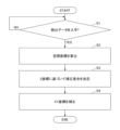
- FIG. 3 is a diagram showing a flowchart representing processing executed by a coordinate calculation unit 130 and a coordinate correction unit 140.
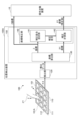
- FIG. 1 is a diagram showing an example of the configuration of an input device 100 according to an embodiment.
- FIG. 1 shows an operation target device 10 that is an input operation target of the input device 100 .
- the origin O of the XYZ coordinates is the center of the operation surface 101 ⁇ /b>A, and the XY coordinates of the origin O match the coordinates of the center of the sensor section 110 .
- a direction parallel to the X axis (X direction), a direction parallel to the Y axis (Y direction), and a direction parallel to the Z axis (Z direction) are orthogonal to each other.
- the XYZ coordinate system is an example of a spatial coordinate system.
- the X-axis is an example of a first axis
- the Y-axis is an example of a second axis
- the Z-axis is an example of a third axis.
- the X, Y, and Z coordinates in the XYZ coordinate system are examples of spatial coordinates.
- the X coordinate is an example of the coordinate value of the first axis
- the Y coordinate is an example of the coordinate value of the second axis
- the Z coordinate is an example of the coordinate value of the third axis.
- the -Z direction side may be referred to as the lower side or the lower side
- the +Z direction side may be referred to as the upper side or the upper side, but this does not represent a universal vertical relationship.
- the top side of a component is the front side
- the bottom side is the back side.
- planar viewing means viewing in the XY plane.
- the length, thickness, thickness, etc. of each part may be exaggerated to make the configuration easier to understand.
- the input device 100 includes a cover 101, a sensor section 110, and a position detection device 100A. Further, the position detection method of the embodiment is a method of detecting the position of the operation input performed by the position detection device 100A.
- a mode in which the user of the input device 100 performs an input operation on the operation surface 101A using the fingertip FT will be described below.
- a fingertip FT is an example of an object that contacts or approaches the operation surface 101A. However, the user may perform an input operation using a part of the body other than the fingertip FT.
- the input device 100 detects the spatial coordinates of the input operation by the user's fingertip FT, corrects the X-coordinate and Y-coordinate (XY-coordinate) according to the Z-coordinate, and outputs the corrected XY-coordinate and Z-coordinate. do.
- the input device 100 may remotely operate the operation-targeted device 10 or may be provided integrally with the operation-targeted device 10 . Also, the input device 100 may be portable, or may be fixedly installed on a wall surface or the like.
- a mode in which the cover 101 and the sensor unit 110 are transparent will be described on the assumption that a display panel (display device) such as liquid crystal or organic EL (Electroluminescence) is arranged below the input device 100.
- the cover 101 and the sensor unit 110 may not be transparent if the panel is not arranged.
- GUI Graphic User Interface
- buttons and the like displayed on the display panel arranged on the back side of the sensor section 110 can be visually recognized through the cover 101 and the sensor section 110 .
- the cover 101 is arranged on the front side of the sensor unit 110 and is, for example, a rectangular plate-like member in a plan view.
- a cover 101 is provided as a top panel that covers the upper surface of the input device 100 .
- the upper surface of the cover 101 is an operation surface 101A.
- the operation surface 101 ⁇ /b>A has a plurality of detection positions corresponding to the plurality of electrodes 112 of the sensor section 110 .
- the origin O of the XYZ coordinates is the center of the operation surface 101A, and the XY plane including the X and Y axes coincides with the operation surface 101A. may not coincide with the center of the operation surface 101A.
- the XY plane including the X axis and the Y axis is a plane parallel to the operation surface 101A.
- the user of the input device 100 touches (touches) the operation surface 101A of the cover 101 with the fingertip FT, or brings the fingertip FT close to the operation surface 101A without touching it (non-contact). allows you to perform input operations.
- a cover 101 is made of transparent glass or resin, for example.
- touch input an input operation of touching the operation surface 101A
- hover input an input operation of approaching without contact
- hover input an input operation of approaching without contact
- “proximity” means that when the fingertip FT approaches the operation surface 101A, the fingertip FT approaches the operation surface 101A to such an extent that a change that can be detected by the position detection device 100A occurs in the capacitance of the sensor unit 110. Say things.
- the sensor section 110 has a substrate 111 and a plurality of electrodes 112 provided on the upper surface of the substrate 111 .
- the sensor unit 110 is a capacitive sensor provided to detect a touch input or hover input to a GUI button based on changes in capacitance of a plurality of electrodes 112 .
- the capacitance of the electrode 112 is an example of a physical quantity representing the degree of contact or proximity of the fingertip FT.
- the substrate 111 may be made of a transparent insulating material, and for example, a transparent substrate made of polyimide can be used.
- a plurality of electrodes 112 are arranged on the upper surface of the substrate 111 .
- the substrate 111 is not limited to a transparent substrate made of polyimide, and substrates made of other materials may be used. Also, a plurality of electrodes 112 may be arranged on the bottom surface of the substrate 111 .
- a plurality of electrodes 112 are arranged in a matrix in the X direction and the Y direction.
- FIG. 1 shows 12 electrodes 112 arranged in three rows in the Y direction and four columns in the X direction, any number of electrodes 112 may be provided.
- the configuration may be such that one or more electrodes 112 are arranged corresponding to one GUI button.
- the electrodes 112 may be linear electrodes extending in the X direction and the Y direction.
- the plurality of electrodes 112 are independent of each other, and are connected to the position detection device 100A via wiring (not shown) routed between them in plan view.
- the plurality of electrodes 112 are composed of transparent electrodes such as ITO (Indium Tin Oxide). If a display panel is not arranged on the back side of the sensor section 110, the plurality of electrodes 112 may be metal plates or the like.
- the detectable range of the electrodes 112 is, for example, within about 30 mm to about 50 mm from the operation surface 101A.
- the electrodes 112 can detect that the fingertip FT is close within about 30 mm to about 50 mm from the operation surface 101A.
- the sensor unit 110 can detect a state in which the fingertip FT touches the operation surface 101A.
- the capacitance of each electrode 112 of the sensor section 110 is detected by the detection section 120 of the position detection device 100A. The capacitance of each electrode 112 changes with touch or hover input.
- the position detection device 100A has a detection section 120 , a coordinate calculation section 130 and a coordinate correction section 140 .
- the coordinate correction unit 140 also has a correction degree setting unit 141 and a correction calculation unit 142 .
- the microcomputer 150 is implemented by a computer including a CPU (Central Processing Unit), RAM (Random Access Memory), ROM (Read Only Memory), an input/output interface, an internal bus, and the like.
- the coordinate calculation unit 130, the coordinate correction unit 140, the correction degree setting unit 141, and the correction calculation unit 142 represent functions of programs executed by the microcomputer 150 as functional blocks.
- the detection unit 120 detects the capacitance of the multiple electrodes 112 of the sensor unit 110 and outputs multiple detection data representing the capacitance at multiple detection positions on the operation surface 101A.
- the detection unit 120 digitally converts the capacitances (analog values) of the plurality of electrodes 112 input from the sensor unit 110 and outputs detection data representing the capacitance of the digital values to the coordinate calculation unit 130 .
- the detection unit 120 applies voltages to the 12 electrodes 112 arranged in 3 rows ⁇ 4 columns in a time division manner in the X direction and the Y direction. You may have the function as a part.
- the coordinate calculation unit 130 calculates the XY coordinates of the touch input or hover input based on the detection data input from the detection unit 120, and calculates the Z coordinate of the touch input or hover input.
- a method of calculating the XY coordinates various methods such as a method of calculating the coordinates of the center of gravity and a method of calculating the position of the peak having the largest capacitance can be used.
- a plurality of detection data for example, 9 out of 12 detection data
- a mode using a method of obtaining the center of gravity of the positions of the plurality of electrodes 112 (for example, the center of gravity of the positions of 12 electrodes 112) as XY coordinates will be described.
- the position of each electrode 112 for example, the position of the center of the XY coordinates of each electrode 112 may be used.
- the coordinate calculation unit 130 calculates the distance according to the capacitance represented by .
- the coordinate calculation unit 130 outputs data representing the calculated XY coordinates and Z coordinates to the coordinate correction unit 140 .
- the coordinate calculation unit 130 also outputs data representing the Z coordinate to the operation-targeted device 10 . Calculating the Z coordinate in this manner corresponds to calculating the Z coordinate based on a plurality of pieces of detection data input from the detection unit 120 .
- the coordinate correction section 140 has a correction degree setting section 141 and a correction calculation section 142 .
- the coordinate corrector 140 corrects the XY coordinates based on the Z coordinate calculated by the coordinate calculator 130 .
- the correction degree setting unit 141 determines the correction degree for correcting the XY coordinates based on the Z coordinate input from the coordinate calculation unit 130 and outputs the correction degree to the correction calculation unit 142 . A specific method for determining the degree of correction will be described later.
- the correction calculation unit 142 corrects the XY coordinates input from the coordinate calculation unit 130 using the correction degree input from the correction degree setting unit 141 . In this manner, the corrected XY coordinates are calculated by the correction calculator 142 .
- the correction calculation unit 142 outputs the corrected XY coordinates to the operation target device 10 . A specific method of calculating the corrected XY coordinates will be described later.
- FIG. 2 is a diagram for explaining the deviation between the center of gravity coordinates and the position of the fingertip FT.
- the coordinates of the center of gravity are the XY coordinates of the fingertip FT calculated by the coordinate calculation unit 130 as the position of the center of gravity.
- the horizontal axis represents the X direction
- the vertical axis represents the capacitance. Since the positional deviation of the barycentric coordinates and the fingertip FT can occur similarly in the X direction and the Y direction, here, for the sake of simplicity of explanation, the positional deviation of the X coordinate of the barycentric coordinates and the fingertip FT in the X direction is will be explained. Also, here, it is assumed that eight electrodes 112 are arranged in the X direction and eight capacitance values are obtained. The positions of the eight electrodes 112 are positions 0 to 7 shown in the X direction.
- FIG. 2 shows the distribution of capacitance in the X direction when touch input or hover input is performed in three patterns (1), (2), and (3), the position of the fingertip FT, and the barycentric coordinate (X coordinate ) and
- the position of the fingertip FT is indicated by a white arrow
- the barycentric coordinates are indicated by a solid black arrow.
- Pattern (1) shows the capacitance distribution when the fingertip FT touches the operation surface 101A near the center in the X direction. That is, this is the case where touch input is performed near the center in the X direction. In this case, the distribution of capacitance changes relatively sharply around the position of the fingertip FT, and a relatively symmetrical distribution in the ⁇ X direction around the position of the fingertip FT is obtained. Since the fingertip FT is in contact with the operation surface 101A, the capacitance is large at the position of the fingertip FT. This is because the capacitance decreases as the distance from the position of the fingertip FT increases.
- the barycentric coordinates are calculated based on the capacitances of the electrodes 112 numbered 0 to 7, so the barycentric coordinates are the fingertip FT. position, and the difference is small.
- the same effect can be obtained by reducing the number of electrodes 112 used for calculating the coordinates of the center of gravity and using the electrodes 112 numbered 1 to 6 or the electrodes 112 numbered 2 to 5 to calculate the coordinates of the center of gravity.
- Pattern (2) shows the capacitance distribution when the fingertip FT touches the operation surface 101A in the -X direction. That is, this is the case where touch input is performed in the -X direction. In this case, the capacitance distribution changes relatively steeply around the position of the fingertip FT. becomes asymmetric in the ⁇ X direction with respect to . Since the fingertip FT is in contact with the operation surface 101A, the capacitance is large at the position of the fingertip FT, but the position of the fingertip FT is offset in the -X direction with respect to the center in the X direction.
- the barycentric coordinates are calculated based on the electrostatic capacitances of the electrodes 112 numbered 0 to 7, the barycentric coordinates are the fingertip FT. It shifts to the center side (+X direction side) in the X direction from the position. Comparing the capacitance of the two electrodes 112 on both sides of the first electrode 112 directly below the position of the fingertip FT, the capacitance of the second electrode 112 located on the center side in the X direction is is larger than the capacitance of the 0th electrode 112 on the outside ( ⁇ X direction side), and the difference is large. is due to the large number of electrodes 112 .
- Pattern (3) shows the capacitance distribution when the fingertip FT is close to the operation surface 101A on the -X direction side. That is, this is the case where hover input is performed in the -X direction.
- the X-direction position of the fingertip FT that performs hover input in pattern (3) is equal to the X-direction position of the fingertip FT that performs touch input in pattern (2).
- the Z position of the fingertip FT is farther from the operation surface 101A than in the case of touch input, and the distance from the operation surface 101A is long.
- the capacitance is less than for touch input. For this reason, the distribution of the capacitance around the position of the fingertip FT becomes gentle, and since the position of the fingertip FT is on the -X direction side, the distribution of the capacitance is in the ⁇ X direction with respect to the position of the fingertip FT. become asymmetric.
- the barycentric coordinates are calculated based on the capacitances of the electrodes 112 numbered 0 to 7, so the barycentric coordinates are the fingertip FT. It shifts to the center side (+X direction side) in the X direction from the position. Since the distribution of the capacitance is gentle, the barycentric coordinates deviate more toward the center than in the case of pattern (2).
- the hover input is an input operation performed without touching the operation surface 101A
- the longer the distance in the Z direction between the operation surface 101A and the fingertip FT the smaller the capacitance of the electrodes 112 from 0 to 7.
- the distribution of capacitance becomes gentle.
- the electrostatic capacitances of the electrodes 112 numbered 0 to 7 become equal, so that the coordinates of the center of gravity shift toward the center.
- the position of the fingertip FT depends on the distance in the Z direction between the operation surface 101A and the fingertip FT.
- the center-of-gravity coordinates shift toward the center as the distance in the Z direction between the operation surface 101A and the fingertip FT increases.
- FIG. 3 is a diagram for explaining deviation of the XY coordinates as the barycentric coordinates calculated by the coordinate calculation unit 130.
- FIG. 3A shows a state in which the sensor section 110 is divided into four equal parts along the X-axis and the Y-axis.
- the origin O of the XYZ coordinates is a point directly above the center of the sensor unit 110 on the operation surface 101A. Therefore, the origin O is shown in the center of the sensor section 110 in FIG.
- the origin O is the center of the sensor section 110 and the operation surface 101A in plan view.
- the Z coordinate of the fingertip FT the XY coordinates as the coordinates of the center of gravity calculated by the coordinate calculation unit 130 were found to be shifted toward the origin O side.
- the distribution of capacitance as in pattern (3) becomes gentler (closer to flatness) as the distance in the Z direction between the operation surface 101A and the fingertip FT increases. It was found that the longer the distance in the Z direction between the operation surface 101A and the fingertip FT, the more the coordinates of the center of gravity shifted toward the center.
- the input device 100 corrects the XY coordinates, which are the coordinates of the center of gravity calculated by the coordinate calculation unit 130, toward the end of the operation surface 101A according to the Z coordinate of the fingertip FT. Bring the XY coordinates closer to the position of the fingertip FT. Further, the input device 100 increases the degree of correction for correcting the center-of-gravity coordinates as the value of the Z coordinate of the fingertip FT increases (as the distance in the Z direction between the operation surface 101A and the fingertip FT increases). The corrected XY coordinates are brought closer to the position of the fingertip FT according to the Z coordinates of .
- the input device 100 increases the degree of correction for correcting the barycentric coordinates as the distance from the center coordinates of the operation surface 101A increases, so that the XY coordinates after correction are corrected in accordance with the Z coordinates of the fingertip FT. to the position of the fingertip FT.
- the correction degree setting unit 141 and the correction calculation unit 142 of the coordinate correction unit 140 perform the following processing.
- the correction degree setting unit 141 sets a correction degree C for correcting the XY coordinates calculated by the coordinate calculation unit 130 based on the Z coordinate calculated by the coordinate calculation unit 130 .
- the correction degree setting unit 141 sets the correction degree C larger as the calculated Z coordinate is larger, and sets the correction degree C smaller as the calculated Z coordinate is smaller.
- the correction degree setting unit 141 sets the degree of correction C to be larger as the XY coordinates calculated by the coordinate calculation unit 130 are farther from the center coordinates of the operation surface 101A. is closer to the center coordinates of the operation surface 101A, the correction degree C is set smaller.
- the correction calculation unit 142 corrects the XY coordinates (X, Y) of the XYZ coordinates (X, Y, Z) calculated by the coordinate calculation unit 130 according to the following equations (1) and (2), for example. Then, the corrected XY coordinates (Xc, Yc) after correction are obtained. An appropriate constant shall be entered for CO .
- the Z coordinate (Z) among the XYZ coordinates (X, Y, Z) calculated by the coordinate calculation unit 130 is used. Note that the center coordinates of the operation surface 101A are (X O , Y O ).
- FIG. 4 is a diagram showing a flowchart representing processing executed by the coordinate calculation unit 130 and the coordinate correction unit 140. As shown in FIG. The flowchart shown in FIG. 4 is a process realized by the microcomputer 150 executing the program stored in the memory.
- the coordinate calculation unit 130 determines whether detection data has been obtained from the detection unit 120 (step S1). When determining that the detection data is not obtained (S1: NO), the coordinate calculation unit 130 repeatedly executes the process of step S1.
- the coordinate calculation unit 130 determines that the detection data has been obtained from the detection unit 120 (S1: YES), it calculates the spatial coordinates based on the capacitance represented by the detection data (step S2).
- the coordinate calculation unit 130 calculates, for example, the XY coordinates of the spatial coordinates as the center-of-gravity coordinates, and calculates the distance according to the capacitance represented by the detection data with the larger amount of change in capacitance as the Z-coordinate of the fingertip FT. do.
- the correction degree setting unit 141 sets a correction degree C for correcting the XY coordinates based on the Z coordinate calculated by the coordinate calculation unit 130 (step S3).
- step S4 the correction calculation unit 142 corrects the XY coordinates (X, Y) calculated by the coordinate calculation unit 130 according to formulas (1) and (2), thereby obtaining the corrected XY coordinates (Xc, Yc) as Calculate (step S4).
- step S4 A series of processes are completed above. When the process of step S4 ends, the flow returns to the start.
- the correction calculation unit 142 corrects either one of the XY coordinates (X, Y) calculated by the coordinate calculation unit 130 according to formula (1) or formula (2), so that the corrected X A coordinate Xc or a Y coordinate Yc may be calculated. For example, if only the X coordinate needs to be corrected or only the Y coordinate needs to be corrected depending on the characteristics of the sensor unit 110, this may be done.
- the X coordinate or the Y coordinate in the spatial coordinates is corrected. Therefore, the distortion of the spatial coordinates calculated by the coordinate calculation unit 130 can be corrected, and the corrected X coordinate or Y coordinate representing the position of the fingertip FT can be calculated.
- the position detection device 100A, the input device 100, and the position detection method that can correct the XY coordinates of the fingertip FT within the operation surface 101A according to the degree of contact or proximity.
- the X-coordinate or Y-coordinate is corrected based on the Z-coordinate calculated by the coordinate calculation unit 130, it is possible to suppress rapid changes in the X-coordinate or Y-coordinate after correction.
- correction can be made so that the Y coordinate changes smoothly and gradually.
- the degree of contact or proximity is represented by the capacitance of the fingertip FT at the detection position, and the coordinate calculation unit 130 calculates the Z-axis coordinate value based on a plurality of detection data represented by the capacitance. do. Since the capacitance between the sensor unit 110 and the fingertip FT changes according to the distance in the Z direction between the operation surface 101A and the fingertip FT, the Z coordinate at the time of contact or proximity can be obtained easily and reliably. can.
- the coordinate correction unit 140 increases the correction degree C for correcting the X coordinate or the Y coordinate as the Z coordinate calculated by the coordinate calculation unit 130 increases.
- the distortion of the spatial coordinates calculated by the coordinate calculation unit 130 increases as the distance in the Z direction between the operation surface 101A and the fingertip FT increases.
- the distortion of the XY coordinates of the space coordinates calculated by the coordinate calculation unit 130 can be corrected according to the Z coordinates of the fingertip FT.
- the coordinate calculation unit 130 calculates the X-coordinate and the Y-coordinate by performing centroid calculation on a plurality of pieces of detection data output from the detection unit 120. Therefore, the influence of noise and the like is suppressed, and the fingertip FT is calculated. can be calculated as XY coordinates.
- the coordinate correction unit 140 corrects the X coordinate or the Y coordinate so as to shift toward the end of the operation surface 101A. Since the XY coordinates as the barycentric coordinates calculated by the coordinate calculation unit 130 are distorted toward the center, the distortion of the XY coordinates calculated by the coordinate calculation unit 130 is corrected by correcting in the direction of shifting to the end side of the operation surface 101A. can do.
- the coordinate correction unit 140 increases the degree of correction C for correcting the X coordinate as the X coordinate is farther from the central coordinate corresponding to the center of the operation surface 101A.
- the X coordinate as the barycentric coordinate calculated by the coordinate calculation unit 130 is greatly distorted toward the center toward the edge of the operation surface 101A. Accordingly, the distortion of the X coordinate calculated by the coordinate calculator 130 can be corrected more appropriately.
- the coordinate correction unit 140 increases the correction degree C for correcting the Y-axis coordinate values as the Y-axis coordinate values are farther from the center coordinates corresponding to the center of the operation surface 101A.
- the Y coordinate which is the barycentric coordinate calculated by the coordinate calculation unit 130, is greatly distorted toward the center toward the ends of the operation surface 101A. Accordingly, the distortion of the Y coordinate calculated by the coordinate calculator 130 can be corrected more appropriately.
- the XY coordinates calculated as the coordinates of the center of gravity are corrected using the degree of correction C set based on the Z coordinate in the spatial coordinates calculated by the coordinate calculation unit 130 .
- correction may be performed according to formulas (1) and (2).
- the coordinate calculation unit 130 calculates If the distortion of the XY coordinates as the barycentric coordinates is small enough to cause no problem, the correction according to the equations (1) and (2) may be performed when the Z coordinate is equal to or greater than the threshold. In this case, if the Z coordinate is less than the threshold, the XY coordinates as the barycentric coordinates calculated by the coordinate calculation unit 130 may be output to the operation target device 10 as they are.
- the position detection device 100A, the input device 100, and the position detection method that can correct the XY coordinates of the fingertip FT within the operation surface 101A according to the degree of contact or proximity can provide.
- the coordinate calculation unit 130 calculates the Z coordinate
- the coordinate correction unit 140 sets the degree of correction C according to the Z coordinate to correct the XY coordinates.
- the Z coordinate is a value inversely proportional to the capacitance of the detection data
- the XY coordinates may be corrected according to the capacitance represented by the detection data without obtaining the Z coordinate.
- the larger the capacitance the smaller the correction degree for correcting the X-coordinate or the Y-coordinate.
- the Z coordinate is a value inversely proportional to the capacitance of the detected data
- the XY coordinates are corrected based on the Z coordinate without obtaining the Z coordinate.
Landscapes
- Engineering & Computer Science (AREA)
- General Engineering & Computer Science (AREA)
- Theoretical Computer Science (AREA)
- Human Computer Interaction (AREA)
- Physics & Mathematics (AREA)
- General Physics & Mathematics (AREA)
- Position Input By Displaying (AREA)
Abstract
接触又は近接の度合に応じて操作面内における物体の二次元座標を補正可能な位置検出装置、入力装置、及び、位置検出方法を提供する。 位置検出装置は、操作面の複数の検出位置において前記操作面への物体の接触又は近接の度合を検出し、前記複数の検出位置における前記度合を表す複数の検出データを出力する検出部と、前記検出部によって検出された複数の検出データに基づいて、前記操作面に平行な平面に含まれる第1軸及び第2軸と、第3軸とを有する空間座標系における前記物体の空間座標を算出する座標算出部と、前記座標算出部によって算出された空間座標における前記第3軸の座標値に基づいて、前記空間座標における前記第1軸の座標値、又は、前記第2軸の座標値を補正する、座標補正部とを含む。
Description
本開示は、位置検出装置、入力装置、及び、位置検出方法に関する。
従来より、タッチ表面に対して非接触のホバー操作を検出する近接センサと、タッチ表面に接触するタッチ操作を検出するタッチセンサとを含み、タッチ表面に対するホバー操作の位置とタッチ操作の位置とのオフセットを補正する入力装置がある(例えば、特許文献1参照)。
ところで、従来の入力装置は、別々のセンサで検出したホバー操作の位置とタッチ操作の位置とのオフセットを補正するものであり、ホバー操作を行う手等の物体の操作面への近接の度合に応じて操作面内における物体の二次元座標を補正するものではない。
そこで、接触又は近接の度合に応じて操作面内における物体の二次元座標を補正可能な位置検出装置、入力装置、及び、位置検出方法を提供することを目的とする。
本開示の実施形態の位置検出装置は、操作面の複数の検出位置において前記操作面への物体の接触又は近接の度合を検出し、前記複数の検出位置における前記度合を表す複数の検出データを出力する検出部と、前記検出部によって検出された複数の検出データに基づいて、前記操作面に平行な平面に含まれる第1軸及び第2軸と、第3軸とを有する空間座標系における前記物体の空間座標を算出する座標算出部と、前記座標算出部によって算出された空間座標における前記第3軸の座標値に基づいて、前記空間座標における前記第1軸の座標値、又は、前記第2軸の座標値を補正する、座標補正部とを含む。
接触又は近接の度合に応じて操作面内における物体の二次元座標を補正可能な位置検出装置、入力装置、及び、位置検出方法を提供することができる。
以下、本開示の位置検出装置、入力装置、及び、位置検出方法を適用した実施形態について説明する。
<実施形態>
図1は、実施形態の入力装置100の構成の一例を示す図である。図1には、入力装置100での入力操作の対象となる操作対象装置10を示す。
図1は、実施形態の入力装置100の構成の一例を示す図である。図1には、入力装置100での入力操作の対象となる操作対象装置10を示す。
以下では、XYZ座標系を定義して説明する。一例として、XYZ座標の原点Oは、操作面101Aの中心であり、原点OのXY座標はセンサ部110の中心の座標と一致する。X軸に平行な方向(X方向)、Y軸に平行な方向(Y方向)、Z軸に平行な方向(Z方向)は、互いに直交する。XYZ座標系は、空間座標系の一例である。X軸は第1軸の一例であり、Y軸は第2軸の一例であり、Z軸は第3軸の一例である。XYZ座標系におけるX座標、Y座標、Z座標は、空間座標の一例である。X座標は第1軸の座標値の一例であり、Y座標は第2軸の座標値の一例であり、Z座標は第3軸の座標値の一例である。
また、以下では、説明の便宜上、-Z方向側を下側又は下、+Z方向側を上側又は上と称す場合があるが、普遍的な上下関係を表すものではない。また、ある構成要素の上面側は表側であり、下面側は裏側である。また、平面視とはXY面視することをいう。また、以下では構成が分かり易くなるように各部の長さ、太さ、厚さ等を誇張して示す場合がある。
入力装置100は、カバー101と、センサ部110と、位置検出装置100Aとを含む。また、実施形態の位置検出方法は、位置検出装置100Aによって行われる操作入力の位置を検出する方法である。以下では、入力装置100の利用者が指先FTを使って操作面101Aに対して入力操作を行う形態について説明する。指先FTは、操作面101Aに接触又は近接する物体の一例である。しかしながら、利用者は指先FT以外の体の部位を利用して入力操作を行ってもよい。
入力装置100は、利用者の指先FTによる入力操作の空間座標を検出し、Z座標に応じてX座標及びY座標(XY座標)を補正して、補正したXY座標と、Z座標とを出力する。入力装置100は、操作対象装置10を遠隔操作するものであってもよく、操作対象装置10に一体的に設けられたものであってもよい。また、入力装置100は、携帯可能であってもよく、壁面等に固定的に設置可能であってもよい。
ここでは入力装置100の下方に液晶や有機EL(Electroluminescence)等のディスプレイパネル(表示装置)が配置されることを想定してカバー101及びセンサ部110が透明である形態について説明するが、例えばディスプレイパネルが配置されないような場合には、カバー101及びセンサ部110は透明ではなくてもよい。センサ部110の裏側に配置されるディスプレイパネルが表示するGUI(Graphic User Interface)のボタン等は、カバー101及びセンサ部110を通じて視認可能である。
<カバー101の構成>
カバー101は、センサ部110の表側に配置され、一例として平面視において矩形状の板状部材である。カバー101は、入力装置100の上面を覆うトップパネルとして設けられている。カバー101の上面は操作面101Aである。操作面101Aには、センサ部110の複数の電極112に対応する複数の検出位置がある。また、上述したように、ここでは一例として、XYZ座標の原点Oは、操作面101Aの中心であり、X軸及びY軸を含むXY平面は操作面101Aと一致するが、XYZ座標の原点Oは、操作面101Aの中心と一致していなくてもよい。この場合には、X軸及びY軸を含むXY平面は、操作面101Aと平行な平面である。
カバー101は、センサ部110の表側に配置され、一例として平面視において矩形状の板状部材である。カバー101は、入力装置100の上面を覆うトップパネルとして設けられている。カバー101の上面は操作面101Aである。操作面101Aには、センサ部110の複数の電極112に対応する複数の検出位置がある。また、上述したように、ここでは一例として、XYZ座標の原点Oは、操作面101Aの中心であり、X軸及びY軸を含むXY平面は操作面101Aと一致するが、XYZ座標の原点Oは、操作面101Aの中心と一致していなくてもよい。この場合には、X軸及びY軸を含むXY平面は、操作面101Aと平行な平面である。
入力装置100の利用者は、カバー101の操作面101Aに指先FTで触れる(タッチ(接触)する)か、又は、操作面101Aに対して指先FTを触れない(非接触)状態で近接させることによって、入力操作を行うことができる。このようなカバー101は、例えば、透明なガラス製又は樹脂製である。
以下では、操作面101Aに触れる入力操作をタッチ入力と称し、非接触で近接させる入力操作をホバー入力と称す。また、近接とは、操作面101Aに対して指先FTが近づくことによって、センサ部110の静電容量に位置検出装置100Aが検出可能な変化が生じるほどに操作面101Aに対して指先FTが近づくことをいう。
<センサ部110の構成>
センサ部110は、基板111と、基板111の上面に設けられる複数の電極112とを有する。センサ部110は、GUIボタンに対するタッチ入力又はホバー入力を、複数の電極112の静電容量の変化によって検知するために設けられている静電容量式のセンサである。電極112の静電容量は、指先FTの接触又は近接の度合を表す物理量の一例である。
センサ部110は、基板111と、基板111の上面に設けられる複数の電極112とを有する。センサ部110は、GUIボタンに対するタッチ入力又はホバー入力を、複数の電極112の静電容量の変化によって検知するために設けられている静電容量式のセンサである。電極112の静電容量は、指先FTの接触又は近接の度合を表す物理量の一例である。
基板111は、透明な絶縁体製であればよく、例えば、ポリイミド製の透明基板を用いることができる。基板111の上面には複数の電極112が配列されている。基板111は、ポリイミド製の透明基板に限らず、他の材質の基板を用いてもよい。また、基板111の下面に複数の電極112が配列されていてもよい。
複数の電極112は、X方向及びY方向にマトリクス状に配列されている。図1には、Y方向に3行、X方向に4列に配列された12個の電極112を示すが、電極112は複数あれば何個あってもよい。1つのGUIボタンに対応して1又は複数の電極112が配置される構成であってよい。また、電極112は、X方向及びY方向に複数本ずつ延在する線状の電極であってもよい。
複数の電極112は、一例として互いに独立しており、平面視で互いの間に引き回される図示しない配線を介して位置検出装置100Aに接続されている。複数の電極112は、例えばITO(Indium Tin Oxide)等の透明電極によって構成される。なお、センサ部110の裏側にディスプレイパネルが配置されない場合には、複数の電極112は金属板等であってもよい。
電極112で検出可能な範囲は、例えば操作面101Aから約30mm以内から約50mm以内である。電極112は、操作面101Aから約30mm以内から約50mm以内で指先FTが近接していることを検出可能である。また、センサ部110は、指先FTが操作面101Aにタッチしている状態を検出可能である。センサ部110の各電極112の静電容量は、位置検出装置100Aの検出部120によって検出される。各電極112の静電容量は、タッチ入力又はホバー入力によって変化する。
<位置検出装置100Aの構成>
位置検出装置100Aは、検出部120、座標算出部130、及び座標補正部140を有する。また、座標補正部140は、補正度合設定部141及び補正計算部142を有する。ここでは一例として、検出部120がIC(Integrated Circuit)で構成され、座標算出部130及び座標補正部140がマイクロコンピュータ150によって構成される形態について説明するが、このような構成に限られるものではない。マイクロコンピュータ150は、CPU(Central Processing Unit)、RAM(Random Access Memory)、ROM(Read Only Memory)、入出力インターフェース、及び内部バス等を含むコンピュータによって実現される。座標算出部130、座標補正部140、補正度合設定部141、及び補正計算部142は、マイクロコンピュータ150が実行するプログラムの機能(ファンクション)を機能ブロックとして示したものである。
位置検出装置100Aは、検出部120、座標算出部130、及び座標補正部140を有する。また、座標補正部140は、補正度合設定部141及び補正計算部142を有する。ここでは一例として、検出部120がIC(Integrated Circuit)で構成され、座標算出部130及び座標補正部140がマイクロコンピュータ150によって構成される形態について説明するが、このような構成に限られるものではない。マイクロコンピュータ150は、CPU(Central Processing Unit)、RAM(Random Access Memory)、ROM(Read Only Memory)、入出力インターフェース、及び内部バス等を含むコンピュータによって実現される。座標算出部130、座標補正部140、補正度合設定部141、及び補正計算部142は、マイクロコンピュータ150が実行するプログラムの機能(ファンクション)を機能ブロックとして示したものである。
検出部120は、センサ部110の複数の電極112の静電容量を検出し、操作面101Aの複数の検出位置における静電容量を表す複数の検出データを出力する。検出部120は、センサ部110から入力される複数の電極112の静電容量(アナログ値)をデジタル変換し、デジタル値の静電容量を表す検出データを座標算出部130に出力する。なお、ここでは詳細な説明を省くが、検出部120は、3行×4列で配置される12個の電極112に時分割的にX方向及びY方向で選択するための電圧を印加する選択部としての機能を有していてもよい。
座標算出部130は、検出部120から入力される検出データに基づいて、タッチ入力又はホバー入力のXY座標を算出するとともに、タッチ入力又はホバー入力のZ座標を算出する。XY座標の算出方法としては、重心座標を算出する方法や、静電容量が最も大きいピークの位置を算出する方法等の様々な方法を利用可能である。ここでは一例として、すべての電極112の静電容量から得られるすべての検出データのうち、静電容量の変化量が大きい複数の検出データ(例えば12個の検出データのうちの9個)に対応する複数の電極112の位置の重心(例えば12個の電極112の位置の重心)をXY座標として求める方法を用いる形態について説明する。各電極112の位置としては、一例として、各電極112のXY座標の中心の位置を用いればよい。
また、Z座標の算出方法には様々な方法があるが、ここでは一例として、すべての電極112の静電容量から得られるすべての検出データのうち、静電容量の変化量が最も大きい検出データが表す静電容量に応じた距離を操作面101Aに対する指先FTのZ座標として座標算出部130が算出する形態について説明する。座標算出部130は、算出したXY座標及びZ座標を表すデータを座標補正部140に出力する。また、座標算出部130は、Z座標を表すデータを操作対象装置10に出力する。このようにしてZ座標を算出することは、検出部120から入力される複数の検出データに基づいてZ座標を算出することに相当する。
座標補正部140は、補正度合設定部141及び補正計算部142を有する。座標補正部140は、座標算出部130によって算出されたZ座標に基づいて、XY座標を補正する。
補正度合設定部141は、座標算出部130から入力されるZ座標に基づいてXY座標を補正するための補正度合を決定し、補正計算部142に出力する。補正度合の具体的な決定方法については後述する。
補正計算部142は、座標算出部130から入力されるXY座標を、補正度合設定部141から入力される補正度合を用いて補正する。このようにして、補正計算部142によって補正後のXY座標が計算される。補正計算部142は、補正後のXY座標を操作対象装置10に出力する。補正後のXY座標の具体的な計算方法については後述する。
<重心座標と指先FTの位置のずれ>
図2は、重心座標と指先FTの位置のずれを説明する図である。ここでは、入力装置100がXY座標を補正しない場合に生じうる、重心座標と指先FTの位置のずれについて説明する。重心座標は、座標算出部130が重心の位置として算出する指先FTのXY座標である。
図2は、重心座標と指先FTの位置のずれを説明する図である。ここでは、入力装置100がXY座標を補正しない場合に生じうる、重心座標と指先FTの位置のずれについて説明する。重心座標は、座標算出部130が重心の位置として算出する指先FTのXY座標である。
図2では横軸はX方向を表し、縦軸は静電容量を表す。重心座標と指先FTの位置のずれは、X方向及びY方向において同様に生じうるため、ここでは説明を簡単にするために、重心座標のうちのX座標と指先FTのX方向の位置のずれについて説明する。また、ここでは、X方向に8つの電極112が配置されていて、8つの静電容量の値が得られることとして説明する。8つの電極112の位置は、X方向に示す0~7の位置である。
図2には3つのパターン(1)、(2)、(3)でタッチ入力又はホバー入力を行った場合のX方向における静電容量の分布と、指先FTの位置と、重心座標(X座標)とを示す。また、指先FTの位置を白抜きの矢印で示し、重心座標を黒塗り潰しの矢印で示す。
パターン(1)は、指先FTがX方向の中央付近で操作面101Aに触れた場合の静電容量の分布を示す。すなわち、X方向の中央付近でタッチ入力を行った場合である。この場合には、指先FTの位置を略中心として静電容量の分布が比較的急峻に変化するとともに、指先FTの位置を略中心として±X方向で比較的対称な分布が得られる。操作面101Aに指先FTが触れているため、指先FTの位置では静電容量が大きくなり、操作面101Aの中央付近に指先FTが触れているため、X方向の中央付近で静電容量が最も大きくなり、指先FTの位置から離れるにつれて静電容量が小さくなるからである。
パターン(1)のような静電容量の分布が得られる場合には、例えば、0番から7番の電極112の静電容量に基づいて重心座標が算出されるため、重心座標は指先FTの位置と略等しくなり、ずれは小さい。なお、重心座標の算出に用いる電極112の数を減らして、1番から6番や、2番から5番の電極112等を用いて重心座標を算出しても同様である。
パターン(2)は、指先FTが-X方向側で操作面101Aに触れた場合の静電容量の分布を示す。すなわち、-X方向側でタッチ入力を行った場合である。この場合には、指先FTの位置を略中心として静電容量の分布が比較的急峻に変化するが、指先FTの位置が-X方向側であるため、静電容量の分布は指先FTの位置に対する±X方向で非対称になる。操作面101Aに指先FTが触れているため、指先FTの位置では静電容量が大きくなるが、指先FTの位置がX方向における中央に対して-X方向側にオフセットしているからである。
パターン(2)のような静電容量の分布が得られる場合には、例えば、0番から7番の電極112の静電容量に基づいて重心座標が算出されるため、重心座標は指先FTの位置よりもX方向の中心側(+X方向側)にずれる。指先FTの位置の真下にある1番の電極112の両隣の2つの電極112の静電容量を比べると、X方向の中心側にある2番の電極112の静電容量の方が、X方向の外側(-X方向側)にある0番の電極112の静電容量よりも大きく、その差が大きいことと、指先FTの位置の真下にある1番の電極112よりも+X方向側の方が電極112の数が多いこととによるものである。
パターン(3)は、指先FTが-X方向側で操作面101Aに近接した場合の静電容量の分布を示す。すなわち、-X方向側でホバー入力を行った場合である。パターン(3)においてホバー入力を行う指先FTのX方向の位置は、パターン(2)においてタッチ入力を行う指先FTのX方向の位置と等しい。
ホバー入力の場合は、指先FTのZ位置がタッチ入力の場合に比べて操作面101Aから離れており、操作面101Aからの距離が長いため、指先FTの真下の1番の電極112の静電容量は、タッチ入力の場合よりも小さくなる。このため、指先FTの位置を略中心とする静電容量の分布は緩やかになり、指先FTの位置が-X方向側であるため、静電容量の分布は指先FTの位置に対する±X方向で非対称になる。
パターン(3)のような静電容量の分布が得られる場合には、例えば、0番から7番の電極112の静電容量に基づいて重心座標が算出されるため、重心座標は指先FTの位置よりもX方向の中心側(+X方向側)にずれる。そして、静電容量の分布は緩やかであることから、パターン(2)の場合よりも重心座標は中心側に大きくずれる。
ホバー入力は、操作面101Aに触れずに行う入力操作であるため、操作面101Aと指先FTとのZ方向の距離が長くなるほど、0番から7番の電極112の静電容量は小さくなり、かつ、静電容量の分布は緩やかになる。静電容量の分布が緩やかになるほど、0番から7番の電極112の静電容量は等しくなる方向になるため、重心座標は中心側に引っ張られるようにずれることになる。
パターン(2)とパターン(3)を比べて分かるように、操作面101Aに対して指先FTで操作を行う場合には、操作面101Aと指先FTとのZ方向の距離によって、指先FTの位置に対する重心座標のずれ方が異なり、操作面101Aと指先FTとのZ方向の距離が大きくなるほど、重心座標は中心側にずれる。
また、パターン(1)とパターン(2)を比べて分かるように、タッチ入力を行う場合に、指先FTのX方向の位置によって、指先FTの位置に対する重心座標のずれ方が異なり、指先FTの位置がX方向の端に行くほど、指先FTの位置と重心座標のずれは大きくなる。次に、図3を用いて、重心座標として算出されるXY座標のずれについて説明する。
<XY座標のずれ>
図3は、座標算出部130が算出する重心座標としてのXY座標のずれを説明する図である。図3(A)には、センサ部110をX軸及びY軸で4等分した状態を示す。ここで、XYZ座標の原点Oは、操作面101Aのうちのセンサ部110の中心の真上の点である。このため、図3(A)には、センサ部110の中央に原点Oを示す。操作面101AのZ座標はZ=0mmである。このため、タッチ入力を行う場合の指先FTのZ方向の位置はZ=0mmである。
図3は、座標算出部130が算出する重心座標としてのXY座標のずれを説明する図である。図3(A)には、センサ部110をX軸及びY軸で4等分した状態を示す。ここで、XYZ座標の原点Oは、操作面101Aのうちのセンサ部110の中心の真上の点である。このため、図3(A)には、センサ部110の中央に原点Oを示す。操作面101AのZ座標はZ=0mmである。このため、タッチ入力を行う場合の指先FTのZ方向の位置はZ=0mmである。
図3(B)には、図3(A)に示すセンサ部110の第2象限内の全領域で、X方向及びY方向に等間隔で指先FTの位置をずらしながら、Z=0mmの位置でタッチ入力を行った場合に得られる重心座標の分布を示す。図3(B)において、ドットで示す各点は、座標算出部130が算出する重心座標としてのXY座標を示す。すなわち、図3(B)は、図3(A)に示すセンサ部110の第2象限内において、X方向では-X方向側の端から+X方向側の端まで、Y方向では-Y方向側の端から+Y方向側の端まで、等間隔で指先FTの位置をずらしながら、Z=0mmの位置でタッチ入力を行った場合に得られる重心座標の分布を示す。
図3(C)には、図3(A)に示すセンサ部110の第2象限内の全領域で、X方向及びY方向に等間隔で指先FTの位置をずらしながら、Z=20mmの位置でホバー入力を行った場合に得られる重心座標の分布を示す。図3(C)において、ドットで示す各点は、座標算出部130が算出する重心座標としてのXY座標を示す。すなわち、図3(C)は、図3(A)に示すセンサ部110の第2象限内において、X方向では-X方向側の端から+X方向側の端まで、Y方向では-Y方向側の端から+Y方向側の端まで、等間隔で指先FTの位置をずらしながら、Z=20mmの位置でホバー入力を行った場合に得られる重心座標の分布を示す。
図3(B)に示すように、Z=0mmの位置でタッチ入力を行った場合に得られる重心座標は、第2象限内の全領域に分布しているため、指先FTの位置を正しく表していると考えられる。
これに対して、図3(C)に示すように、Z=20mmの位置でホバー入力を行った場合に得られる重心座標は、全体的に第2象限内で原点O側にずれており、重心座標に歪みが生じていることが分かる。ここでは第2象限の重心座標のみを示すが、第1象限、第3象限、及び第4象限でも同様に重心座標が原点O側にずれることと考えられる。
また、図3(C)に示すように、Z=20mmの位置でホバー入力を行った場合に得られる重心座標は、原点Oに近い側ではドット同士が比較的等間隔であるが、原点Oから離れるほどドット同士の間隔が短くなって密になっている。これは、原点Oから離れるほど、指先FTの位置に対する重心座標のずれが大きくなっていることを表している。原点Oは、センサ部110及び操作面101Aの平面視での中心である。
以上のような図3(B)及び図3(C)の重心座標の分布の違いと、図2を用いて説明したパターン(2)及び(3)との違いとから、指先FTのZ座標によって、座標算出部130が算出する重心座標としてのXY座標は、原点O側にずれることが分かった。また、ホバー入力を行う場合には、パターン(3)のような静電容量の分布は、操作面101Aと指先FTとのZ方向の距離が長くなるほど緩やかな(平坦に近い)分布になり、操作面101Aと指先FTとのZ方向の距離が長くなるほど重心座標が中心側にずれることが分かった。
このため、入力装置100は、指先FTのZ座標に応じて、座標算出部130が算出する重心座標としてのXY座標を操作面101Aの端部側にずらすように補正することによって、補正後のXY座標を指先FTの位置に近づける。また、入力装置100は、指先FTのZ座標の値が大きいほど(操作面101Aと指先FTとのZ方向の距離が長くなるほど)、重心座標を補正する補正度合を大きくすることで、指先FTのZ座標に応じて、補正後のXY座標を指先FTの位置に近づける。
また、この際に、入力装置100は、操作面101Aの中心座標から離れているほど、重心座標を補正する補正度合を大きくすることで、指先FTのZ座標に応じて、補正後のXY座標を指先FTの位置に近づける。
具体的には、座標補正部140の補正度合設定部141及び補正計算部142が以下のような処理を行う。
補正度合設定部141は、座標算出部130によって算出されたZ座標に基づいて、座標算出部130によって算出されたXY座標を補正する際の補正度合Cを設定する。補正度合設定部141は、算出されたZ座標が大きいほど補正度合Cを大きく設定し、算出されたZ座標が小さいほど補正度合Cを小さく設定する。
また、補正度合設定部141は、座標算出部130によって算出されたXY座標が操作面101Aの中心座標から離れているほど、補正度合Cを大きく設定し、座標算出部130によって算出されたXY座標が操作面101Aの中心座標に近いほど、補正度合Cを小さく設定する。
補正計算部142は、座標算出部130によって算出されたXYZ座標(X,Y,Z)のうちのXY座標(X,Y)を、一例として次式(1)、(2)に従って補正することにより、補正後の補正XY座標(Xc,Yc)を求める。なお、COには適当な定数を入れるものとする。補正XY座標(Xc,Yc)を求める際には、座標算出部130によって算出されたXYZ座標(X,Y,Z)のうちのZ座標(Z)を用いる。なお、操作面101Aの中心座標は(XO,YO)である。ここでは操作面101Aの中心は原点Oに一致するため、中心座標(XO,YO)=(0,0)である。
Xc=XO+(X-XO)×CO×Z (1)
Yc=YO+(Y-YO)×CO×Z (2)
Xc=XO+(X-XO)×CO×Z (1)
Yc=YO+(Y-YO)×CO×Z (2)
なお、この場合において、補正度合Cは補正後の座標と補正前の座標との差分であるため、次式(3)のように表すことができる。

<フローチャート>
図4は、座標算出部130及び座標補正部140が実行する処理を表すフローチャートを示す図である。図4に示すフローチャートは、マイクロコンピュータ150がメモリに格納されているプログラムを実行することによって実現される処理である。
図4は、座標算出部130及び座標補正部140が実行する処理を表すフローチャートを示す図である。図4に示すフローチャートは、マイクロコンピュータ150がメモリに格納されているプログラムを実行することによって実現される処理である。
処理がスタートすると、座標算出部130は、検出部120から検出データを入手したかどうかを判定する(ステップS1)。座標算出部130は、検出データを入手していない(S1:NO)と判定すると、ステップS1の処理を繰り返し実行する。
座標算出部130は、検出部120から検出データを入手した(S1:YES)と判定すると、検出データが表す静電容量に基づいて空間座標を算出する(ステップS2)。座標算出部130は、空間座標のうちのXY座標を一例として重心座標として算出し、静電容量の変化量がもっと大きい検出データが表す静電容量に応じた距離を指先FTのZ座標として算出する。
次いで、補正度合設定部141は、座標算出部130によって算出されたZ座標に基づいて、XY座標を補正する際の補正度合Cを設定する(ステップS3)。
次いで、補正計算部142は、座標算出部130によって算出されたXY座標(X,Y)を式(1)、(2)に従って補正することにより、補正後の補正XY座標(Xc,Yc)を計算する(ステップS4)。以上で一連の処理が終了する。ステップS4の処理が終了すると、フローはスタートにリターンする。
なお、補正計算部142は、座標算出部130によって算出されたXY座標(X,Y)のうちのどちらか一方を式(1)又は式(2)に従って補正することにより、補正後の補正X座標Xc又はY座標Ycを計算してもよい。例えば、センサ部110の特性によって、X座標のみ補正すればよい場合や、Y座標のみ補正すればよい場合には、このようにすればよい。
<効果>
以上のように、座標算出部130によって算出された空間座標におけるZ座標に基づいて、空間座標におけるX座標、又は、Y座標を補正する。このため、座標算出部130によって算出された空間座標の歪みを補正し、指先FTの位置を表す補正後のX座標又はY座標を計算することができる。
以上のように、座標算出部130によって算出された空間座標におけるZ座標に基づいて、空間座標におけるX座標、又は、Y座標を補正する。このため、座標算出部130によって算出された空間座標の歪みを補正し、指先FTの位置を表す補正後のX座標又はY座標を計算することができる。
したがって、接触又は近接の度合に応じて操作面101A内における指先FTのXY座標を補正可能な位置検出装置100A、入力装置100、及び、位置検出方法を提供することができる。また、座標算出部130によって算出されたZ座標に基づいてX座標又はY座標を補正するため、補正後のX座標又はY座標が急激に変化することを抑制でき、Z座標に応じてX座標又はY座標が滑らかに徐々に変化するように補正できる。
また、接触又は近接の度合は、検出位置における指先FTの静電容量で表され、座標算出部130は、静電容量によって表される複数の検出データに基づいて、Z軸の座標値を算出する。センサ部110と指先FTとの間の静電容量は、操作面101Aと指先FTとのZ方向の距離に応じて変化するので、接触又は近接の際のZ座標を容易かつ確実に求めることができる。
また、座標補正部140は、座標算出部130によって算出されたZ座標が大きいほど、X座標、又は、Y座標を補正する補正度合Cを大きくする。座標算出部130によって算出された空間座標の歪みは、操作面101Aと指先FTとの間のZ方向の距離が長いほど大きくなるため、歪みが大きい場合に、より強い補正を行うことができ、指先FTのZ座標に応じて、座標算出部130によって算出された空間座標のXY座標の歪みを補正することができる。
また、座標算出部130は、検出部120から出力された複数の検出データに対して重心計算を行うことにより、X座標及びY座標を算出するので、ノイズ等の影響を抑制して、指先FTのXY平面における重心座標をXY座標として算出できる。
また、座標補正部140は、X座標又はY座標を操作面101Aの端部側にずらすように補正する。座標算出部130が算出する重心座標としてのXY座標は中心側に歪むため、操作面101Aの端部側にずらす方向で補正することにより、座標算出部130によって算出されたXY座標の歪みを補正することができる。
また、座標補正部140は、X座標が操作面101Aの中心に対応する中心座標から離れているほど、X座標を補正する補正度合Cを大きくする。座標算出部130が算出する重心座標としてのX座標は、操作面101Aの端ほど中心側に大きく歪むので、中心座標から離れているほど補正度合Cを大きくすることで、中心座標からの距離に応じて、座標算出部130によって算出されたX座標の歪みをより適切に補正することができる。
また、座標補正部140は、Y軸の座標値が操作面101Aの中心に対応する中心座標から離れているほど、Y軸の座標値を補正する補正度合Cを大きくする。座標算出部130が算出する重心座標としてのY座標は、操作面101Aの端ほど中心側に大きく歪むので、中心座標から離れているほど補正度合Cを大きくすることで、中心座標からの距離に応じて、座標算出部130によって算出されたY座標の歪みをより適切に補正することができる。
<変形例>
以上では、座標算出部130によって算出された空間座標におけるZ座標に基づいて設定する補正度合Cを用いて、重心座標として算出されるXY座標を補正する形態について説明した。
以上では、座標算出部130によって算出された空間座標におけるZ座標に基づいて設定する補正度合Cを用いて、重心座標として算出されるXY座標を補正する形態について説明した。
しかしながら、このように補正度合Cを用いてXY座標を補正する形態に限らず、例えば、座標算出部130によって算出された空間座標のうちのZ座標に対して閾値を設け、Z座標が閾値以上の場合に式(1)、(2)による補正を行うようにしてもよい。例えば、タッチ入力が行われる場合(Z=0mmの場合)や、ホバー入力でも指先FTの位置が操作面101Aに極めて近い(例えばZ座標が5mm未満)の場合に、座標算出部130によって算出される重心座標としてのXY座標の歪みが問題にならない程度に小さい場合には、Z座標が閾値以上の場合に式(1)、(2)による補正を行えばよい。この場合に、Z座標が閾値未満の場合には、座標算出部130によって算出される重心座標としてのXY座標をそのまま操作対象装置10に出力すればよい。
このようにZ座標に閾値を設ける場合においても、接触又は近接の度合に応じて操作面101A内における指先FTのXY座標を補正可能な位置検出装置100A、入力装置100、及び、位置検出方法を提供することができる。
また、以上では、座標算出部130がZ座標を算出し、座標補正部140は、Z座標に応じて補正度合Cを設定してXY座標を補正する形態について説明した。しかしながら、Z座標は検出データの静電容量に反比例する値であるため、Z座標を求めずに、検出データが表す静電容量に応じてXY座標を補正してもよい。この場合には、静電容量が大きいほど、X座標、又は、Y座標を補正する補正度合を小さくすればよい。Z座標は検出データの静電容量に反比例する値であるため、Z座標を求めなくても、Z座標に基づいてXY座標を補正することになる。
以上、本開示の例示的な実施形態の位置検出装置、入力装置、及び、位置検出方法について説明したが、本発明は、具体的に開示された実施形態に限定されるものではなく、特許請求の範囲から逸脱することなく、種々の変形や変更が可能である。
なお、本国際出願は、2021年11月29日に出願した日本国特許出願2021-192686に基づく優先権を主張するものであり、その全内容は本国際出願にここでの参照により援用されるものとする。
100 入力装置
100A 位置検出装置
101 カバー
101A 操作面
110 センサ部
110 センサ部
111 基板
112 電極
120 検出部
130 座標算出部
140 座標補正部
141 補正度合設定部
142 補正計算部
150 マイクロコンピュータ
100A 位置検出装置
101 カバー
101A 操作面
110 センサ部
110 センサ部
111 基板
112 電極
120 検出部
130 座標算出部
140 座標補正部
141 補正度合設定部
142 補正計算部
150 マイクロコンピュータ
Claims (10)
- 操作面の複数の検出位置において前記操作面への物体の接触又は近接の度合を検出し、前記複数の検出位置における前記度合を表す複数の検出データを出力する検出部と、
前記検出部によって検出された複数の検出データに基づいて、前記操作面に平行な平面に含まれる第1軸及び第2軸と、第3軸とを有する空間座標系における前記物体の空間座標を算出する座標算出部と、
前記座標算出部によって算出された空間座標における前記第3軸の座標値に基づいて、前記空間座標における前記第1軸の座標値、又は、前記第2軸の座標値を補正する、座標補正部と
を含む、位置検出装置。 - 前記度合は、前記検出位置における前記物体の静電容量で表され、
前記座標算出部は、前記静電容量によって表される前記複数の検出データに基づいて、前記第3軸の座標値を算出する、請求項1に記載の位置検出装置。 - 前記座標補正部は、前記座標算出部によって算出された前記第3軸の座標値が大きいほど、前記第1軸の座標値、又は、前記第2軸の座標値を補正する補正度合を大きくする、請求項1又は2に記載の位置検出装置。
- 前記座標算出部は、前記検出部から出力された前記複数の検出データに対して重心計算を行うことにより、前記第1軸の座標値、及び、前記第2軸の座標値を算出する、請求項1乃至3のいずれか1項に記載の位置検出装置。
- 前記座標補正部は、前記第1軸の座標値、又は、前記第2軸の座標値を前記操作面の端部側にずらすように補正する、請求項1乃至4のいずれか1項に記載の位置検出装置。
- 前記座標補正部は、前記第1軸の座標値が前記操作面の中心に対応する中心座標から離れているほど、前記第1軸の座標値を補正する補正度合を大きくする、請求項1乃至5のいずれか1項に記載の位置検出装置。
- 前記座標補正部は、前記第2軸の座標値が前記操作面の中心に対応する中心座標から離れているほど、前記第2軸の座標値を補正する補正度合を大きくする、請求項1乃至6のいずれか1項に記載の位置検出装置。
- 前記第1軸と前記第2軸と前記第3軸とは、互いに直交する、請求項1乃至7のいずれか1項に記載の位置検出装置。
- 操作面の裏側に配置され、前記操作面の複数の検出位置における前記操作面への物体の接触又は近接の度合を表す物理量を出力するセンサ部と、
前記度合を検出し、前記複数の検出位置における前記度合を表す複数の検出データを出力する検出部と、
前記検出部によって検出された複数の検出データに基づいて、前記操作面に平行な平面に含まれる第1軸及び第2軸と、第3軸とを有する空間座標系における前記物体の空間座標を算出する座標算出部と、
前記座標算出部によって算出された空間座標における前記第3軸の座標値に基づいて、前記空間座標における前記第1軸の座標値、又は、前記第2軸の座標値を補正する、座標補正部と
を含む、入力装置。 - 操作面の複数の検出位置において前記操作面への物体の接触又は近接の度合を検出し、前記複数の検出位置における前記度合を表す複数の検出データを出力し、
前記検出された複数の検出データに基づいて、前記操作面に平行な平面に含まれる第1軸及び第2軸と、第3軸とを有する空間座標系における前記物体の空間座標を算出し、
前記算出された空間座標における前記第3軸の座標値に基づいて、前記空間座標における前記第1軸の座標値、又は、前記第2軸の座標値を補正する、位置検出方法。
Priority Applications (4)
| Application Number | Priority Date | Filing Date | Title |
|---|---|---|---|
| JP2023563553A JP7725777B2 (ja) | 2021-11-29 | 2022-10-14 | 位置検出装置、入力装置、及び、位置検出方法 |
| CN202280064388.4A CN118020050A (zh) | 2021-11-29 | 2022-10-14 | 位置检测装置、输入装置以及位置检测方法 |
| DE112022005696.7T DE112022005696T5 (de) | 2021-11-29 | 2022-10-14 | Positionserfassungsvorrichtung, eingabevorrichtung und positionserfassungsverfahren |
| US18/627,019 US12314518B2 (en) | 2021-11-29 | 2024-04-04 | Position detection device, input device, and position detection method |
Applications Claiming Priority (2)
| Application Number | Priority Date | Filing Date | Title |
|---|---|---|---|
| JP2021192686 | 2021-11-29 | ||
| JP2021-192686 | 2021-11-29 |
Related Child Applications (1)
| Application Number | Title | Priority Date | Filing Date |
|---|---|---|---|
| US18/627,019 Continuation US12314518B2 (en) | 2021-11-29 | 2024-04-04 | Position detection device, input device, and position detection method |
Publications (1)
| Publication Number | Publication Date |
|---|---|
| WO2023095484A1 true WO2023095484A1 (ja) | 2023-06-01 |
Family
ID=86539222
Family Applications (1)
| Application Number | Title | Priority Date | Filing Date |
|---|---|---|---|
| PCT/JP2022/038375 Ceased WO2023095484A1 (ja) | 2021-11-29 | 2022-10-14 | 位置検出装置、入力装置、及び、位置検出方法 |
Country Status (5)
| Country | Link |
|---|---|
| US (1) | US12314518B2 (ja) |
| JP (1) | JP7725777B2 (ja) |
| CN (1) | CN118020050A (ja) |
| DE (1) | DE112022005696T5 (ja) |
| WO (1) | WO2023095484A1 (ja) |
Cited By (1)
| Publication number | Priority date | Publication date | Assignee | Title |
|---|---|---|---|---|
| WO2025046851A1 (ja) * | 2023-08-31 | 2025-03-06 | 三菱電機ビルソリューションズ株式会社 | 入力装置 |
Citations (4)
| Publication number | Priority date | Publication date | Assignee | Title |
|---|---|---|---|---|
| JP2010108255A (ja) * | 2008-10-30 | 2010-05-13 | Denso Corp | 車載操作システム |
| JP2014013434A (ja) * | 2012-07-03 | 2014-01-23 | Ntt Docomo Inc | 表示装置、処理方法及びプログラム |
| JP2014092988A (ja) * | 2012-11-05 | 2014-05-19 | Ntt Docomo Inc | 端末装置、画面表示方法、ホバー位置補正方法、プログラム |
| JP2014164619A (ja) * | 2013-02-26 | 2014-09-08 | Panasonic Intellectual Property Corp Of America | 電子機器 |
Family Cites Families (3)
| Publication number | Priority date | Publication date | Assignee | Title |
|---|---|---|---|---|
| JP6497941B2 (ja) * | 2015-01-09 | 2019-04-10 | キヤノン株式会社 | 電子機器、その制御方法及びプログラム並びに記録媒体 |
| US11209937B2 (en) | 2019-07-08 | 2021-12-28 | Samsung Electronics Co., Ltd. | Error correction for seamless transition between hover and touch sensing |
| JP7454228B2 (ja) | 2020-06-08 | 2024-03-22 | 株式会社大一商会 | 遊技機 |
-
2022
- 2022-10-14 DE DE112022005696.7T patent/DE112022005696T5/de active Pending
- 2022-10-14 CN CN202280064388.4A patent/CN118020050A/zh active Pending
- 2022-10-14 JP JP2023563553A patent/JP7725777B2/ja active Active
- 2022-10-14 WO PCT/JP2022/038375 patent/WO2023095484A1/ja not_active Ceased
-
2024
- 2024-04-04 US US18/627,019 patent/US12314518B2/en active Active
Patent Citations (4)
| Publication number | Priority date | Publication date | Assignee | Title |
|---|---|---|---|---|
| JP2010108255A (ja) * | 2008-10-30 | 2010-05-13 | Denso Corp | 車載操作システム |
| JP2014013434A (ja) * | 2012-07-03 | 2014-01-23 | Ntt Docomo Inc | 表示装置、処理方法及びプログラム |
| JP2014092988A (ja) * | 2012-11-05 | 2014-05-19 | Ntt Docomo Inc | 端末装置、画面表示方法、ホバー位置補正方法、プログラム |
| JP2014164619A (ja) * | 2013-02-26 | 2014-09-08 | Panasonic Intellectual Property Corp Of America | 電子機器 |
Cited By (1)
| Publication number | Priority date | Publication date | Assignee | Title |
|---|---|---|---|---|
| WO2025046851A1 (ja) * | 2023-08-31 | 2025-03-06 | 三菱電機ビルソリューションズ株式会社 | 入力装置 |
Also Published As
| Publication number | Publication date |
|---|---|
| US20240248567A1 (en) | 2024-07-25 |
| JP7725777B2 (ja) | 2025-08-20 |
| DE112022005696T5 (de) | 2024-09-12 |
| JPWO2023095484A1 (ja) | 2023-06-01 |
| CN118020050A (zh) | 2024-05-10 |
| US12314518B2 (en) | 2025-05-27 |
Similar Documents
| Publication | Publication Date | Title |
|---|---|---|
| US8125454B2 (en) | Resistive type touch panel | |
| US9746971B2 (en) | Touch sensing device and driving method thereof | |
| US9069409B2 (en) | Coordinate algorithm of touch panel | |
| CN105556439A (zh) | 检测传感器以及输入装置 | |
| US9811181B2 (en) | Noise correction for a stylus touch device | |
| JP2011086149A (ja) | 静電容量型タッチセンサ | |
| CN108762653B (zh) | 触碰定位方法、装置及电子设备 | |
| JP2014170334A (ja) | 静電容量式タッチパネルおよびそれを用いた手持ち式電子機器 | |
| US20090114457A1 (en) | Object detection for a capacitive ITO touchpad | |
| JP6024250B2 (ja) | 補正装置、補正プログラム、及び補正方法 | |
| US20140292715A1 (en) | Self-capacitive touch panel | |
| JP6430746B2 (ja) | タッチセンサ | |
| US12314518B2 (en) | Position detection device, input device, and position detection method | |
| CN102859473B (zh) | 指向位置确定设备和方法、触摸板设备、电子设备 | |
| US11644926B2 (en) | Changing a proximity value associated with a capacitance sensor | |
| JP5865724B2 (ja) | 入力装置及び前記入力装置を用いた重心位置の補正方法 | |
| US20240061507A1 (en) | Non-Uniform Pressure Actuation Threshold Value | |
| KR20110105455A (ko) | 3차원 감지 패널 | |
| US11928292B2 (en) | Touchscreen device | |
| US9134862B2 (en) | Parallelogram electrode touch panel | |
| CN107533414A (zh) | 用于力检测器的抖动滤波器 | |
| CN118363497A (zh) | 坐标输入装置 | |
| EP4141627A1 (en) | Controller and method for controlling a mutual capacitive sensor array, and sensor system | |
| WO2025142429A1 (ja) | 押圧センサ、押し込み位置推定方法、及び押し込み位置推定プログラム | |
| US20160342273A1 (en) | Self-capacitive touch sensing devices, touch point positioning method, and display devices |
Legal Events
| Date | Code | Title | Description |
|---|---|---|---|
| 121 | Ep: the epo has been informed by wipo that ep was designated in this application |
Ref document number: 22898268 Country of ref document: EP Kind code of ref document: A1 |
|
| WWE | Wipo information: entry into national phase |
Ref document number: 2023563553 Country of ref document: JP |
|
| WWE | Wipo information: entry into national phase |
Ref document number: 202280064388.4 Country of ref document: CN |
|
| 122 | Ep: pct application non-entry in european phase |
Ref document number: 22898268 Country of ref document: EP Kind code of ref document: A1 |