WO2023095475A1 - 可動部の位置を制御する情報処理装置 - Google Patents
可動部の位置を制御する情報処理装置 Download PDFInfo
- Publication number
- WO2023095475A1 WO2023095475A1 PCT/JP2022/038009 JP2022038009W WO2023095475A1 WO 2023095475 A1 WO2023095475 A1 WO 2023095475A1 JP 2022038009 W JP2022038009 W JP 2022038009W WO 2023095475 A1 WO2023095475 A1 WO 2023095475A1
- Authority
- WO
- WIPO (PCT)
- Prior art keywords
- controller
- movable
- movable part
- information processing
- virtual object
- Prior art date
Links
Images


Classifications
-
- A—HUMAN NECESSITIES
- A63—SPORTS; GAMES; AMUSEMENTS
- A63F—CARD, BOARD, OR ROULETTE GAMES; INDOOR GAMES USING SMALL MOVING PLAYING BODIES; VIDEO GAMES; GAMES NOT OTHERWISE PROVIDED FOR
- A63F13/00—Video games, i.e. games using an electronically generated display having two or more dimensions
- A63F13/25—Output arrangements for video game devices
- A63F13/28—Output arrangements for video game devices responding to control signals received from the game device for affecting ambient conditions, e.g. for vibrating players' seats, activating scent dispensers or affecting temperature or light
- A63F13/285—Generating tactile feedback signals via the game input device, e.g. force feedback
-
- G—PHYSICS
- G06—COMPUTING; CALCULATING OR COUNTING
- G06F—ELECTRIC DIGITAL DATA PROCESSING
- G06F3/00—Input arrangements for transferring data to be processed into a form capable of being handled by the computer; Output arrangements for transferring data from processing unit to output unit, e.g. interface arrangements
- G06F3/01—Input arrangements or combined input and output arrangements for interaction between user and computer
Definitions
- the present disclosure relates to an information processing device, an information processing method, and a program.
- a first member provided with a first movable portion, a second member connected to the first member, and controlling the position of the first movable portion
- An information processing apparatus comprising: a signal acquisition section that acquires a first control signal for the control; and a position control section that controls the position of the first movable section according to the first control signal.
- the computer acquires a first control signal for controlling the position of a first movable portion provided on a first member connected to a second member. and a position control section for controlling the position of the first movable section according to the first control signal.
- FIG. 1 is a diagram illustrating a configuration example of an information processing system according to a first embodiment of the present disclosure
- FIG. It is a figure which shows the functional structural example of a microcomputer.
- Fig. 2 schematically shows the structure of the controller;
- FIG. 10 is a diagram for explaining an example of controlling the position of a movable part according to a virtual object corresponding to a controller;
- FIG. 10 is a diagram showing an example of haptic presentation to the user based on the contact of another virtual object with respect to the virtual object corresponding to the controller;
- FIG. 10 is a diagram showing another example of haptic presentation to the user based on the contact of another virtual object with respect to the virtual object corresponding to the controller;
- FIG. 10 is a diagram showing another example of haptic presentation to the user based on the contact of another virtual object with respect to the virtual object corresponding to the controller;
- FIG. 10 is a diagram showing an example of haptic presentation to a user;
- FIG. 10 is a diagram showing another example of haptic presentation to the user;
- FIG. 10 is a diagram showing another example of haptic presentation to the user;
- FIG. 10 is a diagram showing an example of the relationship between the position command value of the movable part and the weight of the virtual object corresponding to the controller;
- FIG. 5 is a diagram showing an example of a relationship between a position command value and the position of a movable part;
- FIG. 10 is a diagram showing an example of addition of effect signals;
- FIG. 10 is a diagram for explaining an example of pseudo haptic presentation using a nonlinear waveform; It is a figure for demonstrating the modification of the movable range of a movable part.
- FIG. 10 is a diagram showing an example of using controllers when the angle between the controllers is 90 degrees;
- FIG. 5 is a diagram showing an example of a relationship between a position command value and positions of two movable parts;
- FIG. 10 is a diagram for explaining an example of controlling the positions of two movable parts according to a virtual object corresponding to a combination of two controllers;
- FIG. 10 is a diagram showing an example of using controllers when the angle between the controllers is 0 degree;
- FIG. 5 is a diagram showing an example of a relationship between a position command value and positions of two movable parts
- FIG. 10 is a diagram for explaining an example of controlling the positions of two movable parts according to a virtual object corresponding to a combination of two controllers; It is a figure which shows a mode that the cap was removed from the controller.
- FIG. 4 is a diagram showing an example of connection between two controllers via a joint;
- FIG. 10 is a diagram showing an example of direct connection between controllers forming an angle of 0 degrees;
- FIG. 10 is a diagram showing an example of direct connection between controllers forming an angle of 90 degrees;
- FIG. 10 is a diagram showing a display example of guidance prompting connection between controllers;
- FIG. 10 is a diagram showing the state of two controllers before and after connection according to guidance;
- FIG. 4 is a diagram showing four controllers connected to each other; It is a figure which shows the control example of the movable part provided in each of four controllers.
- FIG. 10 is a diagram showing an example in which a controller and an attached member are connected;
- FIG. 10 is a diagram showing another example of connection between the controller and the attached member;
- FIG. 10 illustrates an example in which two controllers are each connected to an attachment;
- FIG. 10 is a diagram showing an example of control of movable parts provided in two controllers connected to an attached member;
- FIG. 10 illustrates an example in which two controllers are each connected to an attachment;
- FIG. 10 illustrates an example in which two controllers are each connected to an attachment;
- FIG. 5 is a diagram showing an example of a relationship between a position command value and the position of a movable part
- FIG. 10 is a diagram showing an example in which attachment members are connected to two types of controllers; It is a figure for demonstrating the 1st modification regarding a movement of a movable part. It is a figure for demonstrating the 2nd modification regarding the movement of a movable part. It is a figure for demonstrating the 3rd modification regarding a movement of a movable part. It is a figure for demonstrating the 4th modification regarding the movement of a movable part. It is a figure for demonstrating the 1st structural example of a movable part.
- FIG. 10 is a diagram showing an example in which attachment members are connected to two types of controllers; It is a figure for demonstrating the 1st modification regarding a movement of a movable part. It is a figure for demonstrating the 2nd modification regarding the movement of a movable part. It is a figure for demonstrating
- FIG. 4 is a diagram for explaining the details of the first configuration example of the movable portion;
- FIG. 10 is a diagram for explaining a second configuration example of the movable portion;
- FIG. 11 is a diagram for explaining details of a second configuration example of the movable portion;
- FIG. 11 is a diagram for explaining a third configuration example of the movable portion;
- a plurality of components having substantially the same or similar functional configurations may be distinguished by attaching different numerals after the same reference numerals.
- attaching different numerals after the same reference numerals.
- similar components in different embodiments may be distinguished by attaching different alphabets after the same reference numerals.
- attaching different alphabets after the same reference numerals.
- only the same reference numerals are used.
- haptic presentation device is an exoskeleton type haptic presentation device.
- a user can be presented with a sensation of grasping something with a hand in a VR (Virtual Reality) space.
- VR Virtual Reality
- a haptic presentation device is a tool-type haptic presentation device (for example, a pen-shaped haptic presentation device or a gun-shaped haptic presentation device).
- a tool-type haptic presentation device is generally made to imitate the shape of a specific tool, and presents a user with a haptic that matches the specific tool. Therefore, it is difficult for such a tool-type haptic presentation device to present a user with haptic sensations corresponding to each of a plurality of types of tools.
- this specification mainly proposes a tool-type, more general-purpose haptic presentation device. Furthermore, this specification also proposes a technique of presenting a haptic sensation to a user by combining a plurality of devices. It is expected that the combination of multiple devices will further improve the types of haptic sensations presented to the user, and that haptic sensations corresponding to more types of tools will be presented to the user.
- FIG. 1 is a diagram showing a configuration example of an information processing system according to the first embodiment of the present disclosure.
- an information processing system 1 includes a controller 10 (first member), a control device 81, a camera 82, and a VR device 83 (display device). and
- the control device 81 is connected to each of the controller 10, camera 82 and VR device 83 by wire or wirelessly.
- the control device 81 is implemented by a computer. As shown in FIG. 1, the control device 81 holds an App (application) 812 in a storage unit (not shown), and a processor (not shown) executes the App 812 to realize a processing unit.
- App 812 may be a game application.
- the type of App 812 is not limited to game applications.
- App 812 may be an application other than a game application.
- the App 812 proceeds based on information transmitted from the controller 10, information transmitted from the VR device 83, or images captured by the camera 82. App 812 then controls the output by VR device 83 based on its progress.
- output by the VR device 83 may include screen display by a display device or audio output by a speaker.
- the information transmitted from the controller 10 can correspond to operation information for controlling the execution of the App 812.
- the information transmitted from the controller 10 may include information indicating that a button provided on the controller 10 has been pressed, or may include information detected by a sensor provided on the controller 10.
- the information transmitted from the VR device 83 may include information indicating that a button provided on the VR device 83 has been pressed, or information detected by a sensor provided on the VR device 83. It's okay.
- the App 812 constructs the VR space.
- An avatar corresponding to the user exists in the VR space.
- the App 812 controls the movement of the avatar within the VR space based on information transmitted from the controller 10, information transmitted from the VR device 83, or images captured by the camera .
- an image of the VR space is provided from the App 812 to the VR device 83 and displayed by the VR device 83 so that the user can visually recognize the VR space.
- the App 812 transmits various control signals to the controller 10 .
- the control device 81 holds an SDK (Software Development Kit) 814 in a storage unit (not shown).
- the SDK 814 is a component required for executing App 812 .
- control device 81 can be assumed to be a game machine.
- control device 81 is not limited to a game machine.
- control device 81 may be a PC (Personal Computer) or the like.
- the camera 82 has an image sensor, and obtains an image by capturing an imaging range with the image sensor. More specifically, the camera 82 obtains a plurality of frames (that is, moving images) by continuously capturing images of the imaging range in chronological order with the image sensor.
- the controller 10 and the VR device 83 may exist within the imaging range of the camera 82 .
- the camera 82 is installed independently of other devices (for example, the controller 10, the control device 81, the VR device 83, etc.). However, camera 82 may be integrated with other devices. For example, the camera 82 may be provided in the VR device 83 or may be provided in the control device 81 .
- the VR device 83 outputs according to control by the App 812 .
- the VR device 83 includes a display device, and performs screen display using the display device under control of the App 812 .
- the VR device 83 includes a speaker, and outputs audio through the speaker under control of the App 812 .
- the VR device 83 can be used by being worn on the user's head. However, the VR device 83 does not necessarily have to be worn on the user's head.
- the VR device 83 is connected to the control device 81 .
- the form of the VR device 83 is not limited.
- the form of the VR device 83 may be a form in which a smart phone is set in goggles and used.
- the form of the VR device 83 may be a form in which the headset operates alone.
- the controller 10 includes a microcomputer 120 (control section), a movable section 130 (first movable section) as an example of a haptic presentation device, a battery 140, an Amp 151, and a VCM as another example of a haptic presentation device. (Voice Coil Motor) 152 .
- the microcomputer 120 corresponds to an MCU (Micro-Control Unit) and can be configured by an integrated circuit on which a processor, memory (recording medium), input/output circuits, and the like are mounted.
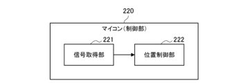
- the functions of the microcomputer 120 can be realized by executing programs stored in the memory by the processor. A functional configuration example of the microcomputer 120 will be described with reference to FIG.
- FIG. 2 is a diagram showing an example of the functional configuration of the microcomputer 120. As shown in FIG. As shown in FIG. 2 , the microcomputer 120 has a signal acquisition section 121 and a position control section 122 . Functions of the signal acquisition unit 121 and the position control unit 122 will be described later in detail. Returning to FIG. 1, the description continues.
- microcomputer 120 may be incorporated in the microcomputer outside the controller 10.
- the movable part 130 includes an origin search switch 131 , a motor driver 132 , a motor 133 and an encoder 134 .
- the movable part 130 has a substrate (not shown) on which these components are arranged.
- the origin switch 131 is a switch used to determine the reference position of the movable part 130 .
- the motor 133 has a function of converting electrical energy into mechanical energy for moving the movable part 130 .
- the motor driver 132 is a driver that controls the motor 133 according to commands output from the microcomputer 120 .
- the encoder 134 has a function of detecting the rotational speed and position of the motor 133 and outputting the detection result to the microcomputer 120 .
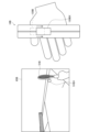
- FIG. 3 is a diagram schematically showing the structure of the controller 10.
- the controller 10 includes a housing E1.
- Various buttons 161 and a trigger button 162 are provided on the outside of the housing E1.
- the various buttons 161 are arranged at positions that are likely to be depressed mainly by the thumb, and the trigger button 162 is arranged at a position that is likely to be depressed mainly by the index finger.
- a drive member 163 is provided inside the housing E1.
- the driving member 163 is connected to the movable section 130 and the housing E1, and uses the mechanical energy generated by the motor 133 to move the movable section 130 in the vertical direction of the controller 10.
- a switch 131 for setting the origin is provided at the lower end of the movable part 130 . Therefore, when the movable part 130 moves downward and comes into contact with the housing E1, the origin search switch 131 is pressed, and the position of the movable part 130 when the origin search switch 131 is pressed is the position of the movable part 130. is used to determine the reference position of
- the position where the switch 131 for setting the origin is provided is not limited.
- the switch 131 for returning to the origin may be provided at the upper end of the movable portion 130 .
- the origin search switch 131 is pressed, and the position of the movable portion 130 when the origin search switch 131 is pressed corresponds to the position of the movable portion 130. It is used to determine the reference position of 130.
- the direction in which the thumb is located with respect to the center of the portion of the controller 10 that is gripped by the user's hand is also referred to as the "upward direction of the controller" for convenience.
- the direction in which the little finger is located with respect to the center of the portion of the controller 10 gripped by the user's hand is also referred to as the “downward direction of the controller.”
- how the user holds the controller 10 is not limited. Returning to FIG. 1, the description continues.
- a battery 140 supplies power to each part of the controller 10 .
- the battery 140 supplies power to the microcomputer 120, Amp 151, motor driver 132 and encoder 134, respectively.
- the battery 140 is provided outside the movable portion 130, but the battery 140 may be included in the movable portion 130 as described later.
- Amp 151 outputs current to VCM 152 based on a current command output from microcomputer 120 .
- VCM152 VCM 152 has a coil and a magnet. A magnetic field is generated by the magnet, and when the current output from the Amp 151 flows through the coil, a force corresponding to the magnetic field and the current is generated in the coil. This causes the VCM 152 to move in a predetermined direction. Furthermore, when the direction of the current flowing through the coil is reversed, the VCM 152 also moves in the direction opposite to the predetermined direction. Therefore, the VCM 152 vibrates due to repeated changes in the direction of the current flowing through the coil.
- a virtual object (first virtual object) corresponding to the controller 10 exists in the VR space constructed by the App 812 of the control device 81 .
- virtual objects representing various tools for example, tennis rackets, swords, etc.
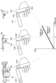
- FIG. 4 is a diagram for explaining an example of controlling the position of the movable part 130 according to the virtual object corresponding to the controller 10.
- FIG. 4 an example in which the VR device 83 displays a VR space image 65A is shown. In this example, no virtual object corresponding to the controller 10 exists in the VR space.
- FIG. 4 an example in which the VR device 83 displays an image 65B in the VR space is shown.
- a virtual object 51B representing a tennis racket exists in the VR space as an example of a virtual object corresponding to the controller 10.
- FIG. an example in which the VR device 83 displays an image 65C in the VR space is shown.
- a virtual object 51C representing a sword exists in the VR space.
- the App 812 may control the position of the movable section 130 based on predetermined parameters of the virtual object corresponding to the controller 10.
- the predetermined parameters may include the weight of the virtual object corresponding to the controller 10.
- FIG. the weight of the virtual object is preset in the App812.
- the App 812 may then control the position of the movable section 130 based on the weight of the virtual object corresponding to the controller 10 .
- the App 812 may control the position of the movable section 130 so that the greater the weight of the virtual object corresponding to the controller 10 is, the farther away from the position the user grips the controller 10 .
- the App 812 may control the position of the movable section 130 such that the greater the weight of the virtual object corresponding to the controller 10, the higher the position of the controller 10 away from the grip position of the controller 10 by the user.
- the App 812 may control the position of the movable part 130A corresponding to the controller 10A to stop at the position where the user grips the controller 10A when the weight of the virtual object corresponding to the controller 10A is zero.
- the App 812 may perform control such that the position of the movable portion 130B corresponding to the controller 10B is further away from the position where the user grips the controller 10B in the upward direction of the controller 10B.
- the App 812 may perform control such that the position of the movable portion 130C corresponding to the controller 10C is further away from the position of the movable portion 130B in the upward direction of the controller 10C.
- the predetermined parameter of the virtual object corresponding to the controller 10 may include the size of the virtual object corresponding to the controller 10.
- FIG. The App 812 may then control the position of the movable section 130 based on the size of the virtual object corresponding to the controller 10 .
- the App 812 may control the position of the movable section 130 so that the larger the virtual object corresponding to the controller 10 is, the farther away from the position the user grips the controller 10 .
- the App 812 may control the position of the movable section 130 such that the larger the virtual object corresponding to the controller 10 is, the more the controller 10 is held upward by the user.
- control example of the position of the movable part 130 is not limited to this example.
- the control example of the position of the movable part 130 may be set in advance along with the progress of the App812. At this time, the App 812 may control the position of the movable section 130 based on its own progress.
- a virtual object existing in the VR space is controlled according to the progress of App 812 .
- a virtual object (second virtual object) different from the virtual object corresponding to the controller 10 may exist in the VR space. At this time, if another virtual object touches the virtual object corresponding to the controller 10, it is desirable that the contact is fed back to the user.
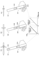
- FIG. 5 is a diagram showing an example of haptic presentation to the user based on the contact of another virtual object with the virtual object corresponding to the controller 10.
- FIG. 5 an example in which the VR device 83 displays a VR space image 65B is shown.
- a virtual object 51B representing a tennis racket exists in the VR space as an example of a virtual object corresponding to the controller 10B.
- a virtual object 51BX representing a ball exists in the VR space as another example of the virtual object.
- the App 812 may change the position of the movable section 130 based on the contact between the virtual object 51B corresponding to the controller 10B and the virtual object 51BX. Thereby, the contact of the virtual object 51BX with the virtual object 51B corresponding to the controller 10B can be fed back to the user. As an example, as shown in FIG. 5, the position of the movable portion 130B may be momentarily moved downward in the controller 10B (eg, to the position of the movable portion 130BX).
- FIG. 6 is a diagram showing another example of haptic presentation to the user based on the contact of another virtual object with the virtual object corresponding to the controller 10.
- FIG. 6 an example is shown in which the VR device 83 displays a VR space image 65C.
- a virtual object 51C representing a sword exists in the VR space as an example of a virtual object corresponding to the controller 10C.
- a virtual object 51CX representing a bamboo exists in the VR space as an example of another virtual object.
- the App 812 may change the position of the movable section 130 based on the contact between the virtual object 51C corresponding to the controller 10C and the virtual object 51CX. Thereby, the contact of the virtual object 51CX with the virtual object 51C corresponding to the controller 10C can be fed back to the user. As an example, as shown in FIG. 6, the position of the movable portion 130C may be momentarily moved downwards in the controller 10C (eg, to the position of the movable portion 130CX).
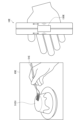
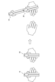
- FIG. 7 is a diagram showing an example of haptic presentation to the user.
- the VR device 83 displays a VR space image 65D.
- a virtual object 51D representing a gun exists in the VR space as an example of a virtual object corresponding to the controller 10D.
- the App 812 changes the position of the movable portion 130D and causes the VCM 152 to vibrate based on the detection of a predetermined user operation on the controller 10 (for example, an operation of pressing the trigger button 162). can be controlled to This can present the user's hand with a force sensation similar to the impact given to the user's hand when the trigger of a gun is pulled.
- a predetermined user operation on the controller 10 for example, an operation of pressing the trigger button 162.
- FIG. 8 is a diagram showing another example of haptic presentation to the user.
- the VR device 83 displays a VR space image 65E
- a virtual object 51E representing a fork exists in the VR space as an example of a virtual object corresponding to the controller 10E.
- a virtual object 51EX representing a pudding exists in the VR space as an example of another virtual object.
- the App 812 may change the position of the movable part 130E and control the VCM 152 to vibrate based on the contact between the virtual object 51E corresponding to the controller 10E and the virtual object 51EX. This can present the user's hand with a tactile sensation similar to the soft feel given to the user's hand when the fork contacts the pudding.
- FIG. 9 is a diagram showing another example of haptic presentation to the user. Referring to FIG. 9, an example in which the VR device 83 displays an image 65F of the VR space is shown. In this example, a virtual object 51F representing waves exists in the VR space.
- the App 812 may change the position of the movable portion 130F and control the VCM 152 to vibrate. This can present a user's hand with a force sensation similar to the vibrations that waves give to the user's hand.
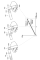
- FIG. 10 is a diagram showing an example of the relationship between the position command value of the movable part 130 and the weight of the virtual object corresponding to the controller 10.
- the position command value of the movable portion 130 corresponding to the lowest position is indicated as X1
- the position command value of the movable portion 130 corresponding to the highest position is indicated as X2.
- the lower limit is the weight corresponding to the lowest
- the upper limit is the weight corresponding to the highest.
- Such lower and upper limits can be arbitrarily set by the user.
- the App 812 controls so that a control signal (first control signal) for controlling the position of the movable section 130 is transmitted to the controller 10 at the timing of controlling the position of the movable section 130.
- the control signal includes a command value for the position of the movable portion 130 (hereinafter also referred to as a “position command value”).
- the timing for controlling the position of the movable portion 130 is as described above.
- the signal acquisition section 121 acquires the control signal transmitted from the control device 81, and the position control section 122 controls the position of the movable section 130 according to the control signal acquired by the signal acquisition section 121. do. More specifically, position control section 122 controls the position of movable section 130 based on the position command value included in the control signal acquired by signal acquisition section 121 .
- FIG. 11 is a diagram showing an example of the relationship between the position command value and the position of the movable part 130.
- FIG. below, it is assumed that the upward direction of the controller 10 is the positive direction of the position of the movable portion 130 .
- the position of the movable portion 130 changes (in the order of movable portion 130A, movable portion 130B, and movable portion 130C).
- the position of the movable part 130 may change linearly with respect to the position command value.
- the position control unit 122 may control the position of the movable unit 130 by notifying the motor driver 132 of an instruction to rotate the motor 133 according to the position command value. More specifically, the position control unit 122 considers the rotation speed and position of the motor 133 output from the encoder 134, and notifies the motor driver 132 of the rotation instruction of the motor 133 according to the position command value, thereby controlling the moving unit. The position of 130 may be controlled.
- FIG. 12 is a diagram showing an example of addition of effect signals.
- FIG. 12 similar to FIG. 11, an example of the relationship between the position command value and the position of the movable portion 130 is shown.
- a position 60 corresponds to the target position of the movable part 130 .
- an effect signal whose addition value changes with time.
- the position control section 122 may obtain an addition signal by adding the position command value and the effect signal. Then, the position control section 122 may control the position of the movable section 130 based on the addition signal.
- FIG. 13 is a diagram for explaining an example of pseudo haptic presentation using a nonlinear waveform.
- the position control unit 122 moves the movable part 130 in one vertical direction of the controller 10 and then moves the movable part 130 in the one direction opposite to the one direction of the controller 10 . It repeats moving slower than the moving speed of In this way, by creating a difference in the acceleration generated in the vertical direction, it is possible to present the user with a pseudo force sensation as if being pulled in the one direction.
- the movable part 130 is always housed in the housing E1 of the controller 10 .
- the movable part 130 may not be housed in the housing E1 of the controller 10 in some cases.
- the movable section 130 may be configured to be movable outside the housing E1 of the controller 10 .
- FIG. 14 is a diagram for explaining a modification of the movable range of the movable part 130.
- controller 11 is shown as a modified example of controller 10 .
- the controller 11 has a movable section 130 .
- the movable part 130 may be configured to be movable to the outside of the housing E1 of the controller 11 (here, the outside of the controller 11 in the downward direction).
- FIG. 15 is a diagram for explaining another modification of the movable range of the movable portion 130.
- controller 12 is shown as a modified example of controller 10 .
- the controller 12 has a movable section 130 .
- the movable part 130 may be configured to be movable to the outside of the housing E1 of the controller 12 (here, the outside of the controller 12 in the upward direction).
- the single controller 10 is held by the user's hand.
- a member (second member) other than the controller 10 may be connected to the controller 10 .
- the type of member connected to the controller 10 is not limited.
- the member connected to the controller 10 is the controller 20 (FIG. 16).
- FIG. 16 is a diagram showing a configuration example of an information processing system according to the second embodiment of the present disclosure.
- an information processing system 2 according to the second embodiment of the present disclosure includes a controller 10 and a control device 81, similar to the information processing system 1 according to the first embodiment of the present disclosure. , a camera 82 and a VR device 83 .
- the information processing system 2 according to the second embodiment of the present disclosure includes a controller 20 connected to the controller 10 .
- controller 10 The functions of the controller 10, the control device 81, the camera 82, and the VR device 83 are the same in the second embodiment of the present disclosure and the first embodiment of the present disclosure. Therefore, in the second embodiment of the present disclosure, detailed descriptions of the functions of the controller 10, control device 81, camera 82, and VR device 83 are omitted.
- the controller 20 includes a microcomputer 220 (control section), a movable section 230 (second movable section) as an example of a haptic device, a battery 240, an Amp 251, and a VCM 252 as another example of a haptic device. and
- the movable part 230 includes an origin search switch 231 , a motor driver 232 , a motor 233 and an encoder 234 .
- the movable part 230 has a substrate (not shown) on which these components are arranged.
- the functions of the movable section 230, the battery 240, the Amp 251 and the VCM 252 are the same as the functions of the movable section 130, the battery 140, the Amp 151 and the VCM 152 according to the first embodiment of the present disclosure. Therefore, detailed descriptions of the functions of battery 240, Amp 251 and VCM 252 are omitted.
- a functional configuration example of the microcomputer 220 will be described with reference to FIG.
- FIG. 17 is a diagram showing a functional configuration example of the microcomputer 220. As shown in FIG. As shown in FIG. 17 , the microcomputer 220 has a signal acquisition section 221 and a position control section 222 . Functions of the signal acquisition unit 221 and the position control unit 222 will be described later in detail. Returning to FIG. 16, the description continues.
- microcomputer 220 may be incorporated in the microcomputer 120 included in the controller 10. At this time, the controller 20 is also electrically connected to the controller 10 . Alternatively, if a microcomputer exists outside controller 10 and controller 20 , the functions of microcomputer 220 may be incorporated in the microcomputer outside controller 10 and controller 20 .
- the control device 81 is connected to each of the controller 10, camera 82 and VR device 83 by wire or wirelessly. In addition, the control device 81 is connected to the controller 20 by wire or wirelessly.
- the connection relationship between the controller 10 and the controller 20 may be one. However, in the embodiment of the present disclosure, it is mainly assumed that there are multiple connection relationships between the controller 10 and the controller 20 .
- the connection relationship between controller 10 and controller 20 may be the angle between controller 10 and controller 20 . More specifically, it is mainly assumed that the angle between the controllers 10 and 20 is 90 degrees and that the angle between the controllers 10 and 20 is 0 degrees.
- FIG. 18 is a diagram showing an example of using controllers when the angle between the controllers is 90 degrees.
- controller 10 and controller 20 are connected so that the angle between controller 10 and controller 20 is 90 degrees.
- a movable part 130 exists inside the housing E1 of the controller 10 .
- a movable part 230 exists inside the housing E2 of the controller 20 .
- the controller 20 is held by the user's hand.
- the direction away from the user's hand is also referred to as the "upward direction of the controller” for convenience.
- the direction in which the controller 10 approaches the user's hand is also referred to as the “downward direction of the controller” for convenience. Note that the user can also hold the controller 10 by hand.
- the App 812 transmits a control signal (first control signal) for controlling the position of the movable portion 130 to the controller 10 at the timing of controlling the position of the movable portion 130 and the position of the movable portion 230. and control so that the control signal (first control signal) is transmitted to the controller 20 .
- the control signal includes a position command value.
- the signal acquisition section 121 acquires the control signal transmitted from the control device 81, and the position control section 122 controls the position of the movable section 130 according to the control signal acquired by the signal acquisition section 121. do. More specifically, position control section 122 controls the position of movable section 130 based on the position command value included in the control signal acquired by signal acquisition section 121 .
- the signal acquisition section 221 acquires the control signal transmitted from the control device 81, and the position control section 222 controls the position of the movable section 230 according to the control signal acquired by the signal acquisition section 221. do. More specifically, the position control section 222 controls the position of the movable section 230 based on the position command value included in the control signal acquired by the signal acquisition section 221 .
- FIG. 19 is a diagram showing an example of the relationship between the position command value and the positions of the movable portion 130 and the movable portion 230.
- FIG. Here, it is assumed that the downward direction of the controller 10 is the positive direction of the position of the movable portion 130 and the downward direction of the controller 20 is the positive direction of the movable portion 230 .
- the position of the movable portion 130 changes (in the order of movable portion 130A, movable portion 130B, and movable portion 130C).
- the controllers 10A-10C For example, the position of the movable part 130 may change linearly with respect to the position command value.
- the position of the movable portion 230 changes (in the order of the movable portion 230A, the movable portion 230B, and the movable portion 230C). It may change down the controllers 20A-20C. For example, the position of the movable part 230 may change linearly with respect to the position command value.
- the movable part 130 and the movable part 230 move simultaneously with respect to one position command value.
- the center-of-gravity positions (60A, 60B, 60C) of the movable part 130 and the movable part 230 change so as to draw a trajectory close to a straight line, and the user may feel an unnatural change in the center-of-gravity position. can be reduced.
- the position control unit 122 may control the position of the movable unit 130 by notifying the motor driver 132 of an instruction to rotate the motor 133 according to the position command value.
- the position control section 222 may control the position of the movable section 230 by notifying the motor driver 232 of an instruction to rotate the motor 233 according to the position command value.
- FIG. 20 is a diagram for explaining an example of controlling the position of the movable section 130 and the position of the movable section 230 according to the virtual object corresponding to the combination of the controllers 10 and 20.
- FIG. 20 a virtual object 52A representing a gun exists in the VR space as an example of a virtual object corresponding to the combination of the controller 10 and the controller 20.
- FIG. 20
- a virtual object 52B representing a gun exists in the VR space as an example of a virtual object corresponding to the combination of the controller 10 and the controller 20. Also, referring to FIG. 20, as an example of a virtual object corresponding to the combination of the controller 10 and the controller 20, a virtual object 52C representing a gun exists in the VR space.
- the App 812 may control the position of the movable section 130 and the position of the movable section 230 based on predetermined parameters of the virtual object corresponding to the combination of the controller 10 and the controller 20.
- the predetermined parameter may include the weight of the virtual object.
- the weight of the virtual object is preset in the App812.
- the App 812 may then control the positions of the movable section 130 and the movable section 230 based on the weight of the virtual object.
- the App 812 may control the positions of the movable section 130 and the movable section 230 such that the greater the weight of the virtual object, the farther away from the gripping position of the controller 20 by the user.
- the App 812 may move the movable part 130 upwards of the controller 10 and the movable part 230 upwards of the controller 20 more greatly as the weight of the virtual object increases.
- the weight of the virtual object 52A is the largest
- the weight of the virtual object 52B is the second largest
- the weight of the virtual object 52C is the smallest.
- the App 812 moves the movable portion 130B and the movable portion 230B corresponding to the virtual object 52B downward from the movable portion 130A and the movable portion 230A corresponding to the virtual object 52A. and the movable portion 130C and the movable portion 230C corresponding to the virtual object 52C may be moved downward from the movable portion 230B.
- FIG. 21 is a diagram showing an example of using the controllers when the angle between the controllers is 0 degrees.
- controller 10 and controller 20 are connected so that the angle between controller 10 and controller 20 is 0 degrees.
- a movable part 130 exists inside the housing E1 of the controller 10 .
- a movable part 230 exists inside the housing E2 of the controller 20 .
- the controller 20 is held by the user's hand.
- the user can also hold the controller 10 by hand.
- the App 812 controls so that a control signal (first control signal) for controlling the position of the movable section 130 is transmitted to the controller 10 at the timing of controlling the position of the movable section 130.
- the control signal includes a position command value.
- the App 812 controls so that a control signal (second control signal) for controlling the position of the movable section 230 is transmitted to the controller 20 at the timing of controlling the position of the movable section 230 .
- the control signal includes a position command value.
- control signal for controlling the position of movable part 130 and the control signal for controlling the position of movable part 230 are different control signals.
- An example of timing for controlling the position of the movable portion 130 and the position of the movable portion 230 will be described later with reference to FIG. 23 .
- the signal acquisition section 121 acquires the control signal (first control signal) transmitted from the control device 81, and the position control section 122 follows the control signal acquired by the signal acquisition section 121. It controls the position of the movable part 130 . More specifically, position control section 122 controls the position of movable section 130 based on the position command value included in the control signal acquired by signal acquisition section 121 .
- the signal acquisition section 221 acquires the control signal (second control signal) transmitted from the control device 81, and the position control section 222 follows the control signal acquired by the signal acquisition section 221. It controls the position of the movable part 230 . More specifically, the position control section 222 controls the position of the movable section 230 based on the position command value included in the control signal acquired by the signal acquisition section 221 .
- FIG. 22 is a diagram showing an example of the relationship between the position command value and the position of the movable part 130 and the position of the movable part 230.
- FIG. it is assumed that the downward direction of the controller 10 is the positive direction of the position of the movable portion 130 and the downward direction of the controller 20 is the positive direction of the movable portion 230 .
- the position of the movable portion 130 changes (in the order of the movable portion 130A and the movable portion 130B) of the controllers 10A to 10B. May change downwards.
- the position of the movable part 130 may change linearly with respect to the position command value.
- the position of the movable section 230 moves (in the order of the movable section 230B and the movable section 230C) to the position below the controllers 20B to 20C. direction may change.
- the position of the movable part 230 may change linearly with respect to the position command value.
- the movable part 130 and the movable part 230 move continuously with respect to different position command values.
- the center-of-gravity positions (60A, 60B, 60C) of the movable part 130 and the movable part 230 gradually change so as to draw a trajectory close to a straight line. .
- FIG. 23 is a diagram for explaining an example of controlling the position of the movable section 130 and the position of the movable section 230 according to the virtual object corresponding to the combination of the controller 10 and the controller 20.
- FIG. 23 a virtual object 53A representing a sword exists in the VR space as an example of a virtual object corresponding to the combination of the controller 10 and the controller 20.
- FIG. 23
- a virtual object 53B representing a sword exists in the VR space as an example of a virtual object corresponding to the combination of the controller 10 and the controller 20.
- a virtual object 53C representing a sword exists in the VR space as an example of a virtual object corresponding to the combination of the controller 10 and the controller 20.
- the App 812 may move the movable section 130 in the upward direction of the controller 10 by a greater amount as the weight of the virtual object increases. Also, the App 812 may move the movable section 230 in the upward direction of the controller 20 by a greater amount as the weight of the virtual object increases.
- the weight of the virtual object 53A is the largest
- the weight of the virtual object 53B is the second largest
- the weight of the virtual object 53C is the smallest.
- the App 812 may move the movable part 130B corresponding to the virtual object 53B downward more than the movable part 130A corresponding to the virtual object 53A. Also, the App 812 may move the movable portion 230C corresponding to the virtual object 53C downward more than the movable portion 230B corresponding to the virtual object 53B.
- the size of the virtual object is preset in the App 812 . Therefore, the predetermined parameter of the virtual object corresponding to the combination of controller 10 and controller 20 may include the size of the virtual object corresponding to the combination of controller 10 and controller 20 . The App 812 may then control the positions of the movable section 130 and the movable section 230 based on the size of the virtual object.
- the App 812 may move the positions of the movable section 130 and the movable section 230 upward as the virtual object becomes larger.
- the App 812 may move the positions of the movable section 130 and the movable section 230 upward as the virtual object becomes larger.
- control example of the position of the movable part 130 and the position of the movable part 230 is not limited to such an example.
- control examples of the position of the movable part 130 and the position of the movable part 230 may be set in advance along with the progress of the App 812 .
- the App 812 may control the position of the movable section 130 and the position of the movable section 230 based on its own progress.
- the App 812 may vary the combination of control of the position of the movable section 130 and the position of the movable section 230 according to the connection relationship between the controller 10 and the controller 20.
- App 812 may determine a combination of control of the position of movable section 130 and the position of movable section 230 according to the angle between controller 10 and controller 20 .
- the angle between the controller 10 and the controller 20 when the angle between the controller 10 and the controller 20 is 0 degrees, the positions of the movable part 130 and the position of the movable part 230 are controlled based on separate control signals.
- the example in which control is performed based on the same control signal when the angle between and is 90 degrees has been described.
- the angle between controller 10 and controller 20 may be other than 0 degrees and 90 degrees.
- the App 812 controls the positions of the movable section 130 and the movable section 230 based on separate control signals when the angle between the controller 10 and the controller 20 is equal to or less than a predetermined angle (eg, 0 degree).
- a predetermined angle eg, 0 degree
- the App 812 controls the positions of the movable section 130 and the movable section 230 based on the same control signal. You may
- connection relationship between the controller 10 and the controller 20 may be selectable by the user.
- the connection relationship between the controller 10 and the controller 20 changes according to the shape of the joint selected by the user.
- the controller 10 and the controller 20 each exist alone, the controller 10 and the controller 20 may each be fitted with a removable cap.
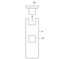
- FIG. 24 is a diagram showing how the cap is removed from the controller 10.
- a cap 76A is fitted to the controller 10, and the cap 76A may be manually removable from the controller 10 by the user. Also, as shown in FIG. 24, the recess of the controller 10 may be exposed after the cap 76A is removed.
- FIG. 25 is a diagram showing an example of connection between the controller 10 and the controller 20 via joints.
- the cap 76B is also fitted to the controller 20, and the cap 76B may be manually removable from the controller 20 by the user. Also, the recess of the controller 20 may be exposed after the cap 76B is removed.
- the user may be able to fit the joint 77 into the recess of the controller 10 and the recess of the controller 20 .
- the controller 10 and the controller 20 are connected at a predetermined angle (here, 90 degrees).
- connection relationship between the controller 10 and the controller 20 may be recognized in any way.
- App 812 may recognize the connection relationship between controller 10 and controller 20 based on sensor data obtained from a predetermined sensor.
- the type of sensor is not limited.
- the controller 10 and the controller 20 are each provided with an acceleration sensor.
- the sensor data may include acceleration measured by the acceleration sensor. That is, the App 812 recognizes the direction of gravity based on the orientation of each of the controller 10 and the controller 20 based on the acceleration measured by these acceleration sensors, and based on the recognized direction of gravity, the controller 10 and the controller 20 connection relationship may be recognized.
- the sensor data may include images captured by the camera 82 . That is, the App 812 may recognize the shape of the joint 77 based on the image captured by the camera 82 and recognize the connection relationship between the controller 10 and the controller 20 based on the recognized shape of the joint 77 .
- the App 812 recognizes the color of the joint 77 based on the image captured by the camera 82, and determines the connection relationship between the controller 10 and the controller 20 based on the shape corresponding to the recognized color of the joint 77. may be recognized.
- the App 812 may attempt to recognize the joint 77 based on the image captured by the camera 82. Then, the App 812 may recognize the connection relationship between the controller 10 and the controller 20 appearing in the image captured by the camera 82 using recognition of the joint 77 as a trigger.
- Controller 10 and controller 20 may be directly connected without any other member.
- connecting portions are provided at a plurality of different locations on the controller 20, and by changing the connecting portion of the controller 20 with which the connecting portions of the controller 10 are brought into contact, the connection relationship between the controller 10 and the controller 20 can be changed.
- the microcomputer 120 and the microcomputer 220 may recognize which connection parts are in contact by receiving an electrical signal from the contact parts caused by the contact between the connection parts.
- the combination of the connecting portion of the controller 10 and the connecting portion of the controller 20 may be configured by combining a magnet and a terminal.
- FIG. 26 is a diagram showing an example of direct connection between controllers forming an angle of 0 degrees.
- connection portions 78A to 78C are provided on the bottom surface of the controller 10.
- connecting portions 79A to 79C are provided on the upper surface of the controller 20.
- the connecting portions 78A to 78C are formed by convex portions
- the connecting portions 79A to 79C are formed by concave portions
- the connecting portions 78A to 78C are fitted to the connecting portions 79A to 79C, whereby the controller 10 and the controller 20 are connected. are connected at an angle of 0 degrees.
- the connecting portions 78A to 78C may be configured by concave portions
- the connecting portions 79A to 79C may be configured by convex portions.
- connection portions 78A to 78C and the connection portions 79A to 79C may be attracted to each other by magnetic force.
- connecting portions 79D to 79F are provided on the side surface of the controller 20, connecting portions 79D to 79F are provided.
- the connection portions 79D to 79F are used for direct connection between controllers forming an angle of 90 degrees. An example of this is described below with reference to FIG.
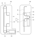
- FIG. 27 is a diagram showing an example of direct connection between controllers forming an angle of 90 degrees.
- the connecting portions 78A to 78C are formed by convex portions
- the connecting portions 79D to 79F are formed by concave portions
- the connecting portions 78A to 78C are fitted to the connecting portions 79D to 79F
- Controller 10 and controller 20 are connected at an angle of 90 degrees.
- the connecting portions 78A to 78C may be configured by concave portions
- the connecting portions 79D to 79F may be configured by convex portions.
- connection portions 78A to 78C and the connection portions 79D to 79F may be attracted to each other by magnetic force.
- the connecting portions of the controller 20 are provided at a plurality of different locations (upper surface and side surface) has been described.
- the connecting portions of the controller 10 may be provided at different locations.
- the connection relationship between the controller 10 and the controller 20 may be changed by changing the connection portion of the controller 10 with which the connection portion of the controller 20 is brought into contact.
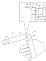
- FIG. 28 is a diagram showing a display example of guidance prompting connection between controllers.
- guidance is displayed on the VR device 83 prompting connection between the controllers.
- the guidance includes a message prompting the connection of the controllers (here, the message "Put the left-hand controller on top of the right-hand controller so that it forms a sword shape") and an image of the two controllers after connection. and are included.
- FIG. 29 is a diagram showing the state of the two controllers before and after connection according to the guidance. Referring to the left half of FIG. 29, the user holds controller 10 in his left hand and controller 20 in his right hand. When the user follows the guidance and puts the left-hand controller 10 on top of the right-hand controller 20, the controller 10 is connected on top of the controller 20 as shown in the right half of FIG.
- the first embodiment of the present disclosure has mainly described the case of one controller, and the second embodiment of the present disclosure has mainly described the case of two controllers. However, more than two controllers may be connected together. Even in such a case, connection at arbitrary points among the three or more controllers may be made in the same manner as the connection between controllers described in the second embodiment of the present disclosure.
- FIG. 30 is a diagram showing a state in which four controllers are connected to each other.
- controller 10 and controller 20 are connected, controller 20 and controller 30 are connected, controller 30 and controller 40 are connected, and controller 40 and controller 10 are connected.
- the controller 30 has a movable portion 330 and the controller 40 has a movable portion 430 .
- the functions of the controllers 30 and 40 may be the same as the functions of the controller 10 . Therefore, detailed description of the functions of each of the controllers 30 and 40 is omitted. As a specific application example, it is assumed that the user is presented with a force sensation similar to the force sensation given to the user's hand when the weight moves on the plate inside the controllers 10 to 40. be done.
- FIG. 31 is a diagram showing a control example of movable parts provided in each of the four controllers. Referring to FIG. 31, three combinations of the positions of the movable parts 130 to 430 (that is, the movable parts 130A to 430A provided in the controllers 10A to 40A, the movable parts 130B to 430B provided in the controllers 10B to 40B, Movable parts 130C-430C) provided in controllers 10C-40C are shown.
- the position command value X controls the positions of the movable parts 230 and 430
- the position command value Y controls the positions of the movable parts 130 and 330 . That is, the App 812 may provide two or more dimensional position command values to three or more controllers when three or more controllers are connected to each other. This allows finer control over the haptic presented to the user.
- a member (second member) connected to one controller may be a member other than the controller (hereinafter also referred to as an "attachment member").
- the attached member can also be referred to as an "attachment.”
- FIG. 32 is a diagram showing an example in which the controller and attached members are connected. Referring to FIG. 32, controller 10 and attachment member 71 are connected.
- the attachment member 71 is formed to imitate the shape of the grip portion of a sword, and the lower surface of the controller 10 and the attachment member 71 are connected.
- the member held by the user's hand is the attached member 71, and by moving the controller 10 away from the holding position, it is possible to increase the moment of the movable portion 130 with a slight change in the position of the movable portion 130. It becomes possible.
- the controller 10 may be moved away from the gripping position by connecting the controller 10 upward to the attachment member 71 .
- the attached member 71 does not have a function as a controller and does not have a battery. Therefore, normally, the attached member 71 receives an operation of pressing a button from the user or presents vibration to the user by means of a VCM. It is considered difficult to
- the controller 10 has a battery 140.
- the controller 10 may then provide the power of the battery 140 to the accessory member 71 . This allows the attachment member 71 to operate using power provided by the controller 10 .
- the attached member 71 can use the power provided from the controller 10 to accept an operation of pressing a button from the user, or to present vibration to the user through VCM.
- the connecting portions of the controller 10 and the attached member 71 are preferably made of a material that conducts electricity.
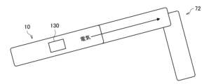
- FIG. 33 is a diagram showing another example in which the controller and attached members are connected. Referring to FIG. 33, controller 10 and attachment member 72 are connected.
- the attachment member 72 is formed to imitate the shape of the grip portion of a gun, and the lower surface of the controller 10 and the attachment member 72 are connected.
- the member held by the user's hand is the attached member 72, and by moving the controller 10 away from the holding position, it is possible to increase the moment of the movable portion 130 with a slight change in the position of the movable portion 130. It becomes possible.
- the controller 10 may be moved away from the gripping position by connecting the controller 10 upwardly of the attachment member 72 .
- the controller 10 may provide the power of the battery 140 to the attachment member 72 . This allows attachment member 72 to operate using power provided by controller 10 . At this time, since the controller 10 and the attached member 72 must be electrically connected, the connecting portions of the controller 10 and the attached member 72 are preferably made of a material that conducts electricity.
- the attached member 71 shown in FIG. 32 and the attached member 72 shown in FIG. 33 have different shapes. These attachment member 71 and attachment member 72 may be separately prepared in advance. Alternatively, it may be possible for the user to arbitrarily create either the attached member 71 or the attached member 72 by rearranging the shape of one attached member.
- FIG. 34 is a diagram showing an example in which two controllers are each connected to an attached member. As shown in FIG. 34 , not only the controller 10 and the attached member 73 are connected, but also the controller 20 may be connected to the attached member 73 .
- controller 10 and the controller 20 may be fitted into the two grooves.
- controller 10 and controller 20 may be connectable in parallel to attachment member 73 . Controller 10 and controller 20 may thereby correspond to the grip portion of a handle formed by controller 10 , attachment 73 and controller 20 .
- the position of the movable part 130 and the position of the movable part 230 may be controlled according to one position command value.
- 35A and 35B are diagrams showing control examples of the movable parts provided in each of the two controllers connected to the attached member 73.
- FIG. 35 three combinations of the positions of the movable parts 130 and the movable parts 230 (that is, the movable parts 130A and 230A provided in the controllers 10A and 20A, the movable parts 130B provided in the controllers 10B and 20B, 230B, movable parts 130C, 230C provided in the controllers 10C, 20C) are shown.
- the position of the movable part 130 and the position of the movable part 230 are controlled by one position command value. Then, according to the change in the position command value, the position of movable portion 130 and the position of movable portion 230 change in opposite directions. This can present the user with a force sensation in the direction in which the handle rotates.
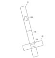
- FIG. 36 is a diagram showing an example in which two controllers are connected to attached members. As shown in FIG. 36 , not only the controller 10 and the attached member 74 are connected, but also the controller 20 may be further connectable to the attached member 74 .
- a groove may be formed in the attachment member 74, and the controller 20 may be fitted into the groove.
- controller 20 may be connectable in an orientation orthogonal to the orientation of attachment member 74 . Accordingly, the controller 20 can correspond to the sword guard portion of the sword formed by the controller 10 , the attachment member 74 and the controller 20 .
- movable portion 230 may be controlled by App 812 to vibrate. This may present the user's hand with a haptic similar to the haptic experienced by the user's hand when the sword is impacted.
- FIG. 37 is a diagram showing an example of the relationship between the position command value and the position of the movable part 130.
- FIG. Here, it is assumed that the upward direction of the controller 10 is the positive direction of the position of the movable portion 130 .
- the position of the movable portion 130 changes (in the order of movable portion 130A, movable portion 130B, and movable portion 130C).
- the position of the movable part 130 may vary upwards of the controllers 10A-10C.
- the position of the movable part 130 may change linearly with respect to the position command value.
- the position of movable part 230 does not have to change based on the position command value.
- FIG. 38 is a diagram showing an example in which the attached member 71 is connected to two types of controllers. Referring to FIG. 38, not only the controller 10 and the attached member 71 are connected, but also the attached member 71 and the controller 21 are connected.
- the controller 21 is a general controller with no moving parts according to embodiments of the present disclosure.
- tools of various shapes for example, swords, guns, etc. can be created by changing the shape of the attached member 71.
- the part that is held by the user's hand is not the attached member 71 but the controller 21 and has a battery. Therefore, it becomes possible for the controller 21 to receive an operation of pressing a button from the user, and to present vibration to the user through the VCM. Along with this, the controller 10 does not need to be provided with a battery and buttons, so that a moving space for the movable part 130 can be easily secured.
- the controller 21 may provide battery power to the controller 10 via the accessory member 71 . This allows controller 10 to operate using power provided from controller 21 . More specifically, the controller 10 can move the movable part 130 using the electric power provided from the controller 21 .
- the connecting portions of the controller 10 and the attached member 71 are preferably made of a material that conducts electricity.
- the connecting portions of the controller 21 and the attached member 71 are preferably made of a material that conducts electricity.
- FIG. 39 is a diagram for explaining a first modification regarding movement of the movable section 130.
- a movable section 130 is provided inside a housing E11 of the controller 10.
- the position control section 122 may change the position of the movable section 130 so as to draw a curved line based on the position command value.
- the housing E11 may have a grip portion E12 that is gripped by the user's hand.
- FIG. 40 is a diagram for explaining a second modification regarding the movement of the movable section 130.
- a movable section 130 is provided inside a housing E13 of the controller 10. As shown in FIG. Further, the housing E13 is connected to a housing E14 held by the user via a rotating shaft E15.
- the position control section 122 may change the position of the movable section 130 so as to draw a curve by rotating the housing E13 about the rotation axis E15 based on the position command value.
- FIG. 41 is a diagram for explaining a third modification regarding the movement of the movable section 130.
- a movable part 130 is provided inside an elongated housing E16. Further, the housing E16 is connected to a housing E14 held by the user via a rotating shaft E15.
- the position control section 122 may change the position of the movable section 130 so as to draw a curve by rotating the housing E16 with respect to the rotation axis E15 based on the position command value.
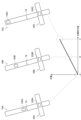
- FIG. 42 is a diagram for explaining a fourth modification regarding the movement of the movable section 130.
- FIG. 42 the controller 10 according to the second modification shown in FIG. 40 is shown.
- FIG. 42 also shows a controller 20 according to the second embodiment of the present disclosure, in which a housing E13 of the controller 10 and the controller 20 are connected.
- the position control unit 122 may change the position of the movable unit 130 so as to draw a curve by rotating the housing E13 with respect to the rotation axis E15 based on the position command value.
- the position of the movable portion 230 provided in the controller 20 also changes so as to draw a curved line.
- a gun-shaped tool is created.
- the position control unit 122 can create a sword-shaped tool by rotating the housing E13 so that the housing E14 and the housing E13 are aligned in a straight line.
- FIG. 43 is a diagram for explaining a first configuration example of the movable section 130.
- a controller 10G as an example of the controller 10 is shown.
- a movable part 130 and a substrate 135 are provided in the controller 10G.
- a motor 133 is arranged on the substrate 135 . That is, the motor 133 exists outside the movable portion 130 .
- the controller 10G is provided with a pulley K1, a pulley K2 and a belt B1.
- a movable portion 130 is connected to both ends of the belt B1. Further, the pulley K1 and the pulley K2 are in contact with the same side of the belt B1 and fixed to the housing E1. In this state, when the motor 133 applies a rotational driving force to the pulley K2, the belt B1 moves in contact with the pulley K1 and the pulley K2 as the pulley K2 rotates, and the movable portion 130 connected to the belt B1 moves. moves up and down.
- the motor 133 which is the main heavy object, exists outside the movable part 130. Therefore, the weight ratio of the movable part 130 relative to the overall weight of the controller 10G is not very high, and it is difficult to improve the quality of the force sensation presented to the user.
- a controller 10H as an example of the controller 10 is also shown.
- a substrate 135 is provided in the controller 10H, and a motor 133 is provided in the movable section 130.
- a battery may also be located on substrate 135 . At this time, the battery is also included in the movable part 130 .
- the controller 10H is provided with pulleys K1 to K3 and a belt B1. Both ends of the belt B1 are connected to the housing E1.
- the pulleys K1, K3, and K2 are in contact with the opposite side of the belt B1, and the pulleys K1 to K3 are connected to the movable portion .
- the motor 133 and the battery are inside the movable part 130. Therefore, since the weight ratio of the movable part 130 with respect to the overall weight of the controller 10H is increased, the quality of the haptic sensation presented to the user is improved.
- FIG. 44 is a diagram for explaining the details of the first configuration example of the movable section 130.
- rails R1 and R2 are fixed to housing E1, and movable section 130 is configured to be movable on these rails R1 and R2.
- the substrate 135 is one layer in the example shown in FIG. 44, the substrate 135 may be divided into a plurality of layers. The multiple layers may then be configured to overlap each other.
- FIG. 45 is a diagram for explaining a second configuration example of the movable section 130.
- a controller 10J as an example of the controller 10 is shown.
- the controller 10J is provided with a board 135 on which a motor 133 is arranged.
- Board 135 and motor 133 are included in movable portion 130 .
- a battery may also be located on substrate 135 . At this time, the battery is also included in the movable part 130 .
- the controller 10J is provided with pulleys K1 and K2 and a belt B1. Both ends of the belt B1 are connected to the housing E1. Also, the pulley K1 and the pulley K2 are in contact with the opposite side of the belt B1, and the pulley K1 and the pulley K2 are connected to the movable portion 130 .
- the motor 133 and the battery exist inside the movable part 130 . Therefore, the weight ratio of the movable part 130 relative to the overall weight of the controller 10J is increased, so the quality of the force sensation presented to the user is improved.
- FIG. 46 is a diagram for explaining the details of the second configuration example of the movable section 130.
- rails R1 and R2 are fixed to housing E1, and movable section 130 is configured to be movable on these rails R1 and R2.
- the substrate 135 is one layer in the example shown in FIG. 46, the substrate 135 may be divided into a plurality of layers. The multiple layers may then be configured to overlap each other.
- FIG. 47 is a diagram for explaining a third configuration example of the movable section 130.
- a controller 10L as an example of the controller 10 is shown.
- a board 135 is provided in the controller 10L, and a motor 133 is arranged on the board 135 .
- Board 135 and motor 133 are included in movable portion 130 .
- a battery may also be located on substrate 135 . At this time, the battery is also included in the movable part 130 .
- the controller 10L is provided with a pulley K1, a belt B2 and a belt B3.
- One end of the belt B2 is connected to the housing E1, and the other end is connected to the pulley K1.
- One end of the belt B3 is connected to the housing E1, and the other end is connected to the pulley K1.
- the belts B2 and B3 are wound around the pulley K1 in opposite directions.
- the motor 133 applies a rotational driving force (for example, a counterclockwise rotational driving force when viewed from above the paper surface) to the pulley K1
- a rotational driving force for example, a counterclockwise rotational driving force when viewed from above the paper surface
- the belt B2 is applied to the pulley K1 as the pulley K1 rotates.
- the amount of winding increases, the amount of winding of the belt B3 around the pulley K1 decreases, the pulley K1 rises, and the movable portion 130 connected to the pulley K1 moves upward.
- the controller 10M is the controller after the movable part 130 has moved upward.
- the motor 133 gives a rotational driving force (for example, a clockwise rotational driving force when viewed from above the paper surface) to the pulley K1
- a rotational driving force for example, a clockwise rotational driving force when viewed from above the paper surface
- the winding amount of the belt B2 around the pulley K1 decreases as the pulley K1 rotates.
- the amount of winding of the belt B3 around the pulley K1 increases, the pulley K1 descends, and the movable part 130 connected to the pulley K1 moves downward.
- the motor 133 and the battery exist inside the movable part 130 . Therefore, since the weight ratio of the movable part 130 with respect to the overall weight of the controller 10L is increased, the quality of the haptic sensation presented to the user is improved.
- a first member provided with a first movable portion, a second member connected to the first member, and controlling the position of the first movable portion
- An information processing apparatus comprising: a signal acquisition section that acquires a first control signal for the control; and a position control section that controls the position of the first movable section according to the first control signal.
- a first member provided with a first movable portion; a second member connected to the first member; a signal acquisition unit that acquires a first control signal for controlling the position of the first movable unit; a position control section that controls the position of the first movable section according to the first control signal; An information processing device.
- the second member is provided with a second movable portion, The position control section controls the position of the second movable section according to the first control signal or a second control signal different from the first control signal.
- the combination of position control of the first movable part and the second movable part differs depending on the connection relationship between the first member and the second member, The information processing device according to (2) above.
- the connection relationship includes an angle between the first member and the second member; the combination is determined based on the angle; The information processing device according to (3) above.
- the angle between the first member and the second member is equal to or less than a predetermined angle, the position of the first movable portion is controlled based on the first control signal, and the second The position of the second movable part is controlled based on the control signal of The information processing device according to (4) above.
- the position of the first movable portion and the position of the second movable portion are controlled based on the first control signal. Both positions are controlled, The information processing device according to (4) above.
- the position of the first movable part is controlled based on a predetermined parameter of a first virtual object corresponding to the first member, The information processing apparatus according to any one of (1) to (6) above.
- the predetermined parameter includes the size or weight of the virtual object; The position of the first movable part is controlled such that the larger the size or the weight, the further away from the gripping position of the first member.
- the position of the first movable part is controlled based on the progress of the application;
- the position of the first movable part changes based on contact between a first virtual object and a second virtual object corresponding to the first member in the application.
- the information processing device according to (9) above. (11) the first member and the second member are directly connected;
- (12) The first member and the second member are indirectly connected via another member,
- (13) The connection relationship is recognized based on sensor data,
- the sensor data includes acceleration measured by an acceleration sensor provided on the first member and the second member, or an image captured by a camera, The information processing device according to (13) above.
- one of the first member and the second member includes a controller that transmits operation information for controlling execution of an application; The other of the first member and the second member operates using power supplied from the controller, The information processing apparatus according to any one of (1) to (14) above.
- the first movable part is configured to be movable outside the housing of the first member, The information processing apparatus according to any one of (1) to (15) above.
- the first movable part includes a motor, The information processing apparatus according to any one of (1) to (16) above.
- the first movable part includes a battery, The information processing apparatus according to any one of (1) to (17) above. (19) Acquiring a first control signal for controlling the position of a first movable portion provided on a first member connected to a second member; a processor controlling the position of the first movable part according to the first control signal; A method of processing information, comprising: (20) the computer, a signal acquisition unit for acquiring a first control signal for controlling the position of the first movable part provided in the first member connected to the second member; a position control section that controls the position of the first movable section according to the first control signal; A program that functions as an information processing device comprising
Abstract
【課題】より多くの種類の力覚をユーザに提示することが可能な技術が提供されることが望まれる。 【解決手段】第1の可動部が設けられた第1の部材と、前記第1の部材と接続された第2の部材と、前記第1の可動部の位置を制御するための第1の制御信号を取得する信号取得部と、前記第1の制御信号に従って前記第1の可動部の位置を制御する位置制御部と、を備える、情報処理装置が提供される。
Description
本開示は、情報処理装置、情報処理方法およびプログラムに関する。
近年、ユーザに力覚を提示する装置(以下、「力覚提示装置」とも言う。)が知られている。例えば、並進と回転とを組み合わせて曲線状の疑似的な力覚を提示する力覚提示装置が開示されている(例えば、特許文献1参照)。
しかしながら、より多くの種類の力覚をユーザに提示することが可能な技術が提供されることが望まれる。
本開示のある観点によれば、第1の可動部が設けられた第1の部材と、前記第1の部材と接続された第2の部材と、前記第1の可動部の位置を制御するための第1の制御信号を取得する信号取得部と、前記第1の制御信号に従って前記第1の可動部の位置を制御する位置制御部と、を備える、情報処理装置が提供される。
また、本開示の別の観点によれば、第2の部材と接続された第1の部材に設けられた第1の可動部の位置を制御するための第1の制御信号を取得することと、プロセッサが、前記第1の制御信号に従って前記第1の可動部の位置を制御することと、を備える、情報処理方法が提供される。
また、本開示の別の観点によれば、コンピュータを、第2の部材と接続された第1の部材に設けられた第1の可動部の位置を制御するための第1の制御信号を取得する信号取得部と、前記第1の制御信号に従って前記第1の可動部の位置を制御する位置制御部と、を備える情報処理装置として機能させるプログラムが提供される。
以下に添付図面を参照しながら、本開示の好適な実施の形態について詳細に説明する。なお、本明細書及び図面において、実質的に同一の機能構成を有する構成要素については、同一の符号を付することにより重複説明を省略する。
また、本明細書および図面において、実質的に同一または類似の機能構成を有する複数の構成要素を、同一の符号の後に異なる数字を付して区別する場合がある。ただし、実質的に同一または類似の機能構成を有する複数の構成要素の各々を特に区別する必要がない場合、同一符号のみを付する。また、異なる実施形態の類似する構成要素については、同一の符号の後に異なるアルファベットを付して区別する場合がある。ただし、類似する構成要素の各々を特に区別する必要がない場合、同一符号のみを付する。
なお、説明は以下の順序で行うものとする。
0.概要
1.第1の実施形態
1.1.システム構成例
1.2.可動部の位置制御の例
1.3.仮想オブジェクト同士の接触
1.4.VCMの振動
1.5.仮想オブジェクトの重さ設定
1.6.可動部の位置制御の手法
1.7.エフェクト信号の加算
1.8.非線形波形による疑似力覚提示
1.9.可動部の可動範囲
2.第2の実施形態
2.1.システム構成例
2.2.コントローラ同士の角度が90度の場合
2.3.コントローラ同士の角度が0度の場合
2.4.補足事項
2.5.接続関係に応じた位置制御
2.6.コントローラ同士の間接的な接続
2.7.接続関係の認識
2.8.コントローラ同士の直接的な接続
2.9.コントローラ同士の接続を促すガイダンス
3.各種の変形例
3.1.互いに接続されるコントローラの数
3.2.付属部材が接続される場合
3.3.可動部の移動に関する変形例
3.4.可動部の構成例
4.まとめ
<0.概要>
まず、本開示の実施形態の概要について説明する。近年、様々な種類の力覚提示装置が存在する。力覚提示装置の一例として、外骨格型の力覚提示装置が挙げられる。外骨格型の力覚提示装置によれば、VR(Virtual Reality)空間内において手で何かを把持した感覚がユーザに提示され得る。
まず、本開示の実施形態の概要について説明する。近年、様々な種類の力覚提示装置が存在する。力覚提示装置の一例として、外骨格型の力覚提示装置が挙げられる。外骨格型の力覚提示装置によれば、VR(Virtual Reality)空間内において手で何かを把持した感覚がユーザに提示され得る。
力覚提示装置の他の一例として、道具型の力覚提示装置(例えば、ペン型の力覚提示装置または銃型の力覚提示装置など)が挙げられる。道具型の力覚提示装置は、特定の道具の形状を模して作られ、その特定の道具に合わせた力覚をユーザに提示するのが一般的である。それゆえに、このような道具型の力覚提示装置は、複数種類の道具それぞれに対応する力覚をユーザに提示するのが困難であるという実情がある。
そこで、本明細書においては、道具型のより汎用的な力覚提示装置について主に提案する。さらに、本明細書においては、複数のデバイスの組み合わせによってユーザに力覚を提示する技術についても提案する。複数のデバイスの組み合わせにより、ユーザに提示される力覚の種類がさらに向上することが期待されるとともに、より多くの種類の道具に対応する力覚がユーザに提示されることが期待される。
以上、本開示の実施形態の概要について説明した。
<1.第1の実施形態>
続いて、本開示の第1の実施形態について詳細に説明する。
続いて、本開示の第1の実施形態について詳細に説明する。
(1.1.システム構成例)
まず、本開示の第1の実施形態に係る情報処理システムの構成例について説明する。
まず、本開示の第1の実施形態に係る情報処理システムの構成例について説明する。
図1は、本開示の第1の実施形態に係る情報処理システムの構成例を示す図である。図1に示されるように、本開示の第1の実施形態に係る情報処理システム1は、コントローラ10(第1の部材)と、制御装置81と、カメラ82と、VRデバイス83(表示装置)とを備える。制御装置81は、コントローラ10、カメラ82およびVRデバイス83それぞれと、有線または無線により接続されている。
(制御装置81)
制御装置81は、コンピュータによって実現される。図1に示されるように、制御装置81は、図示しない記憶部に、App(アプリケーション)812を保持しており、図示しないプロセッサによって、App812が実行されることにより処理部が実現され得る。典型的に、App812は、ゲームアプリケーションであってよい。しかし、App812の種類はゲームアプリケーションに限定されない。例えば、App812は、ゲームアプリケーション以外のアプリケーションであってもよい。
制御装置81は、コンピュータによって実現される。図1に示されるように、制御装置81は、図示しない記憶部に、App(アプリケーション)812を保持しており、図示しないプロセッサによって、App812が実行されることにより処理部が実現され得る。典型的に、App812は、ゲームアプリケーションであってよい。しかし、App812の種類はゲームアプリケーションに限定されない。例えば、App812は、ゲームアプリケーション以外のアプリケーションであってもよい。
App812は、コントローラ10から送信された情報、VRデバイス83から送信された情報、または、カメラ82によって撮像された画像に基づいて進行する。そして、App812は、自身の進行に基づいて、VRデバイス83による出力を制御する。例えば、VRデバイス83による出力には、表示装置による画面表示またはスピーカによる音声出力が含まれ得る。
ここで、コントローラ10から送信された情報は、App812の実行を制御するための操作情報に該当し得る。例えば、コントローラ10から送信された情報は、コントローラ10に設けられたボタンが押下されたことを示す情報を含んでもよいし、コントローラ10に設けられたセンサによって検出された情報を含んでもよい。同様に、VRデバイス83から送信された情報は、VRデバイス83に設けられたボタンが押下されたことを示す情報を含んでもよいし、VRデバイス83に設けられたセンサによって検出された情報を含んでもよい。
より詳細に、App812は、VR空間を構築する。VR空間には、ユーザに対応するアバタが存在する。App812は、コントローラ10から送信された情報、VRデバイス83から送信された情報、または、カメラ82によって撮像された画像に基づいて、VR空間内においてアバタの動きを制御する。このとき、VR空間の画像が、App812からVRデバイス83に提供され、VRデバイス83によって表示されることによってVR空間がユーザに視認され得る。
また、App812は、コントローラ10に対して各種の制御信号を送信する。さらに、制御装置81は、図示しない記憶部に、SDK(Software Development Kit)814を保持している。SDK814は、App812の実行に必要な部品である。
なお、典型的に、制御装置81は、ゲーム機である場合が想定され得る。しかし、制御装置81は、ゲーム機に限定されない。例えば、制御装置81は、PC(Personal Computer)などであってもよい。
(カメラ82)
カメラ82は、イメージセンサを有しており、イメージセンサによって撮像範囲を撮像することによって画像を得る。より詳細に、カメラ82は、イメージセンサによって撮像範囲を時系列に沿って連続的に撮像することによって複数のフレーム(すなわち、動画像)を得る。例えば、カメラ82の撮像範囲には、コントローラ10およびVRデバイス83が存在し得る。
カメラ82は、イメージセンサを有しており、イメージセンサによって撮像範囲を撮像することによって画像を得る。より詳細に、カメラ82は、イメージセンサによって撮像範囲を時系列に沿って連続的に撮像することによって複数のフレーム(すなわち、動画像)を得る。例えば、カメラ82の撮像範囲には、コントローラ10およびVRデバイス83が存在し得る。
なお、典型的に、カメラ82は、他の装置(例えば、コントローラ10、制御装置81およびVRデバイス83など)とは独立して設置されている場合が想定される。しかし、カメラ82は、他の装置と一体化されていてもよい。例えば、カメラ82は、VRデバイス83に設けられていてもよいし、制御装置81に設けられていてもよい。
(VRデバイス83)
VRデバイス83は、App812による制御に従った出力を行う。例えば、VRデバイス83は、表示装置を含んでおり、App812による制御に従って表示装置により画面表示を行う。あるいは、VRデバイス83は、スピーカを含んでおり、App812による制御に従ってスピーカにより音声出力を行う。
VRデバイス83は、App812による制御に従った出力を行う。例えば、VRデバイス83は、表示装置を含んでおり、App812による制御に従って表示装置により画面表示を行う。あるいは、VRデバイス83は、スピーカを含んでおり、App812による制御に従ってスピーカにより音声出力を行う。
なお、典型的に、VRデバイス83は、ユーザの頭部に装着して使用され得る。しかし、VRデバイス83は、必ずしもユーザの頭部に装着されなくてもよい。
また、図1に示された例では、VRデバイス83の形態は、制御装置81に接続される形態である。しかし、VRデバイス83の形態は限定されない。例えば、VRデバイス83の形態は、スマートフォンをゴーグルにセットして使用される形態であってもよい。あるいは、VRデバイス83の形態は、ヘッドセット単体で動作する形態であってもよい。
(コントローラ10)
コントローラ10は、マイコン120(制御部)と、力覚提示装置の例としての可動部130(第1の可動部)と、バッテリ140と、Amp151と、力覚提示装置の他の例としてのVCM(Voice Coil Motor)152とを備える。
コントローラ10は、マイコン120(制御部)と、力覚提示装置の例としての可動部130(第1の可動部)と、バッテリ140と、Amp151と、力覚提示装置の他の例としてのVCM(Voice Coil Motor)152とを備える。
(マイコン120)
マイコン120は、MCU(Micro-Control Unit)に該当し、プロセッサ、メモリ(記録媒体)、入出力回路などが実装された集積回路によって構成され得る。マイコン120が有する機能は、メモリによって記憶されたプログラムがプロセッサによって実行されることによって実現され得る。図2を参照しながら、マイコン120の機能構成例について説明する。
マイコン120は、MCU(Micro-Control Unit)に該当し、プロセッサ、メモリ(記録媒体)、入出力回路などが実装された集積回路によって構成され得る。マイコン120が有する機能は、メモリによって記憶されたプログラムがプロセッサによって実行されることによって実現され得る。図2を参照しながら、マイコン120の機能構成例について説明する。
図2は、マイコン120の機能構成例を示す図である。図2に示されるように、マイコン120は、信号取得部121と、位置制御部122とを備える。なお、信号取得部121および位置制御部122それぞれが有する機能については、後に詳細に説明する。図1に戻って説明を続ける。
なお、コントローラ10の外部にマイコンが存在する場合には、マイコン120が有する機能は、コントローラ10の外部に存在するマイコンに組み込まれていてもよい。
(可動部130)
可動部130は、原点だしのスイッチ131と、モータドライバ132と、モータ133と、エンコーダ134とを備える。その他、可動部130は、これらの部品が配置される図示しない基板を備える。
可動部130は、原点だしのスイッチ131と、モータドライバ132と、モータ133と、エンコーダ134とを備える。その他、可動部130は、これらの部品が配置される図示しない基板を備える。
原点だしのスイッチ131は、可動部130の基準位置を決めるために用いられるスイッチである。モータ133は、電気的エネルギーを、可動部130を移動させるための機械的エネルギーに変換する機能を有する。モータドライバ132は、マイコン120から出力される指令に従ってモータ133の制御を行うドライバである。エンコーダ134は、モータ133の回転速度および位置などを検出し、検出結果をマイコン120に出力する機能を有する。
図3は、コントローラ10の構造を概略的に示す図である。図3に示されるように、コントローラ10は、筐体E1を含んでいる。筐体E1の外側には、各種ボタン161およびトリガーボタン162が設けられている。各種ボタン161は、主に親指によって押下されやすい位置に配置され、トリガーボタン162は、主に人差し指によって押下されやすい位置に配置されている。
各種ボタン161が押下された場合には、各種ボタン161が押下されたことを示す情報がマイコン120を介してApp812に出力される。同様に、トリガーボタン162が押下された場合には、トリガーボタン162が押下されたことを示す情報がマイコン120を介してApp812に出力される。
筐体E1の内側には、駆動部材163が設けられている。例えば、駆動部材163は、可動部130および筐体E1と接続されており、モータ133によって生じた機械的エネルギーを用いて、可動部130をコントローラ10の上下方向に移動させる。
可動部130の下端には、原点だしのスイッチ131が設けられている。したがって、可動部130が下方向に移動し、筐体E1に接触したときに原点だしのスイッチ131が押下され、原点だしのスイッチ131が押下されたときの可動部130の位置が、可動部130の基準位置を決めるために用いられる。
原点だしのスイッチ131が設けられる位置は限定されない。例えば、原点だしのスイッチ131は、可動部130の上端に設けられていてもよい。このとき、可動部130が上方向に移動し、筐体E1に接触したときに原点だしのスイッチ131が押下され、原点だしのスイッチ131が押下されたときの可動部130の位置が、可動部130の基準位置を決めるために用いられる。
なお、図3に示されるように、本開示の実施形態においては、ユーザが親指を小指の上方に位置するようにして、コントローラ10を把持する場合を主に想定する。
したがって、以下の説明においては、コントローラ10のうち、ユーザの手によって把持される部分の中央を基準として、親指がある方向を便宜的に「コントローラの上方向」とも言う。また、コントローラ10のうち、ユーザの手によって把持される部分の中央を基準として、小指がある方向を便宜的に「コントローラの下方向」とも言う。しかし、ユーザがコントローラ10をどのように把持するかは限定されない。図1に戻って説明を続ける。
(バッテリ140)
バッテリ140は、コントローラ10の各部に電力を供給する。例えば、バッテリ140は、マイコン120、Amp151、モータドライバ132およびエンコーダ134それぞれに対して、電力を供給する。なお、図1に示された例では、バッテリ140は、可動部130の外部に設けられているが、後にも説明するように、バッテリ140は、可動部130に含まれていてもよい。
バッテリ140は、コントローラ10の各部に電力を供給する。例えば、バッテリ140は、マイコン120、Amp151、モータドライバ132およびエンコーダ134それぞれに対して、電力を供給する。なお、図1に示された例では、バッテリ140は、可動部130の外部に設けられているが、後にも説明するように、バッテリ140は、可動部130に含まれていてもよい。
(Amp151)
Amp151は、マイコン120から出力される電流指令に基づいて電流をVCM152に出力する。
Amp151は、マイコン120から出力される電流指令に基づいて電流をVCM152に出力する。
(VCM152)
VCM152は、コイルおよび磁石を有する。磁石によって磁界が生じており、Amp151から出力された電流がコイルに流れると、磁界と電流とに応じた力がコイルに生じる。これによって、VCM152が所定の方向に移動する。さらに、コイルを流れる電流の向きが逆向きになると、VCM152も所定の方向と逆向きに移動する。したがって、コイルを流れる電流の向きの変化が繰り返されることによって、VCM152が振動する。
VCM152は、コイルおよび磁石を有する。磁石によって磁界が生じており、Amp151から出力された電流がコイルに流れると、磁界と電流とに応じた力がコイルに生じる。これによって、VCM152が所定の方向に移動する。さらに、コイルを流れる電流の向きが逆向きになると、VCM152も所定の方向と逆向きに移動する。したがって、コイルを流れる電流の向きの変化が繰り返されることによって、VCM152が振動する。
(1.2.可動部130の位置制御の例)
続いて、可動部130の位置制御の例について説明する。制御装置81のApp812によって構築されるVR空間には、コントローラ10に対応する仮想オブジェクト(第1の仮想オブジェクト)が存在する。例えば、コントローラ10に対応する仮想オブジェクトの例としては、各種の道具(例えば、テニスラケット、剣など)を示す仮想オブジェクトなどが想定される。一例として、コントローラ10に対応する仮想オブジェクトに応じて可動部130の位置を制御することが想定され得る。
続いて、可動部130の位置制御の例について説明する。制御装置81のApp812によって構築されるVR空間には、コントローラ10に対応する仮想オブジェクト(第1の仮想オブジェクト)が存在する。例えば、コントローラ10に対応する仮想オブジェクトの例としては、各種の道具(例えば、テニスラケット、剣など)を示す仮想オブジェクトなどが想定される。一例として、コントローラ10に対応する仮想オブジェクトに応じて可動部130の位置を制御することが想定され得る。
図4は、コントローラ10に対応する仮想オブジェクトに応じて可動部130の位置を制御する例を説明するための図である。図4を参照すると、VRデバイス83によって、VR空間の画像65Aが表示される例が示されている。この例においては、コントローラ10に対応する仮想オブジェクトがVR空間に存在していない。
さらに、図4を参照すると、VRデバイス83によって、VR空間の画像65Bが表示される例が示されている。この例においては、コントローラ10に対応する仮想オブジェクトの例としてテニスラケットを示す仮想オブジェクト51BがVR空間に存在している。また、VRデバイス83によって、VR空間の画像65Cが表示される例が示されている。この例においては、コントローラ10に対応する仮想オブジェクトの例として剣を示す仮想オブジェクト51CがVR空間に存在している。
App812は、コントローラ10に対応する仮想オブジェクトの所定のパラメータに基づいて可動部130の位置を制御してもよい。ここで、所定のパラメータは、コントローラ10に対応する仮想オブジェクトの重さを含んでもよい。例えば、仮想オブジェクトの重さは、App812にあらかじめ設定されている。そして、App812は、コントローラ10に対応する仮想オブジェクトの重さに基づいて、可動部130の位置を制御してもよい。
例えば、可動部130の位置が、コントローラ10の把持位置(例えば、把持位置の中央)から離れるほど、可動部130のモーメントが大きくなるため、ユーザがコントローラ10の重さを大きく感じやすくなる。そこで、App812は、コントローラ10に対応する仮想オブジェクトの重さが大きいほど、ユーザによるコントローラ10の把持位置から離れるように可動部130の位置を制御してもよい。
例えば、App812は、コントローラ10に対応する仮想オブジェクトの重さが大きいほど、ユーザによるコントローラ10の把持位置からコントローラ10の上方向に離れるように可動部130の位置を制御してもよい。
図4に示された例では、VR空間の画像65Aが表示されている場合に、コントローラ10Aに対応する仮想オブジェクトの重さがゼロであり、重さが最も小さい。App812は、コントローラ10Aに対応する仮想オブジェクトの重さがゼロである場合に、コントローラ10Aに対応する可動部130Aの位置がユーザによるコントローラ10Aの把持位置に静止するように制御してもよい。
また、VR空間の画像65Bが表示されている場合において、コントローラ10Bに対応する仮想オブジェクト51Bの重さがゼロよりも大きくなる。このとき、App812は、コントローラ10Bに対応する可動部130Bの位置がユーザによるコントローラ10Bの把持位置よりもコントローラ10Bの上方向に離れるように制御してもよい。
さらに、VR空間の画像65Cが表示されている場合において、コントローラ10Cに対応する仮想オブジェクト51Cの重さは、仮想オブジェクト51Bの重さよりも大きいとする。このとき、App812は、コントローラ10Cに対応する可動部130Cの位置が可動部130Bの位置よりも、コントローラ10Cの上方向に離れるように制御してもよい。
なお、仮想オブジェクトの大きさが、App812にあらかじめ設定されている場合も想定される。そこで、コントローラ10に対応する仮想オブジェクトの所定のパラメータは、コントローラ10に対応する仮想オブジェクトの大きさを含んでもよい。そして、App812は、コントローラ10に対応する仮想オブジェクトの大きさに基づいて、可動部130の位置を制御してもよい。
例えば、App812は、コントローラ10に対応する仮想オブジェクトが大きいほど、ユーザによるコントローラ10の把持位置から離れるように可動部130の位置を制御してもよい。例えば、App812は、コントローラ10に対応する仮想オブジェクトが大きいほど、ユーザによるコントローラ10の把持位置からコントローラ10の上方向に離れるように可動部130の位置を制御してもよい。
なお、ここでは、コントローラ10に対応する仮想オブジェクトの重さまたは大きさに基づいて、可動部130の位置が制御される例について説明した。しかし、可動部130の位置の制御例は、かかる例に限定されない。例えば、可動部130の位置の制御例は、App812の進行に沿ってあらかじめ設定されていてもよい。このとき、App812は、自身の進行に基づいて可動部130の位置を制御してもよい。
(1.3.仮想オブジェクト同士の接触)
VR空間に存在する仮想オブジェクトは、App812の進行に応じて制御される。例えば、コントローラ10に対応する仮想オブジェクトとは異なる他の仮想オブジェクト(第2の仮想オブジェクト)がVR空間に存在する場合があり得る。このとき、コントローラ10に対応する仮想オブジェクトに対する、当該他の仮想オブジェクトの接触があった場合には、当該接触がユーザにフィードバックされるのが望ましい。
VR空間に存在する仮想オブジェクトは、App812の進行に応じて制御される。例えば、コントローラ10に対応する仮想オブジェクトとは異なる他の仮想オブジェクト(第2の仮想オブジェクト)がVR空間に存在する場合があり得る。このとき、コントローラ10に対応する仮想オブジェクトに対する、当該他の仮想オブジェクトの接触があった場合には、当該接触がユーザにフィードバックされるのが望ましい。
図5は、コントローラ10に対応する仮想オブジェクトに対する他の仮想オブジェクトの接触に基づくユーザへの力覚提示の一例を示す図である。図5を参照すると、VRデバイス83によって、VR空間の画像65Bが表示される例が示されている。この例においては、コントローラ10Bに対応する仮想オブジェクトの例としてテニスラケットを示す仮想オブジェクト51BがVR空間に存在している。また、他の仮想オブジェクトの例としてボールを示す仮想オブジェクト51BXがVR空間に存在している。
このとき、App812は、コントローラ10Bに対応する仮想オブジェクト51Bと仮想オブジェクト51BXとが接触したことに基づいて、可動部130の位置を変化させてもよい。これによって、コントローラ10Bに対応する仮想オブジェクト51Bに対する仮想オブジェクト51BXの接触がユーザにフィードバックされ得る。一例として、図5に示されるように、可動部130Bの位置は、コントローラ10Bの下方向に(例えば、可動部130BXの位置まで)瞬間的に移動されてもよい。
図6は、コントローラ10に対応する仮想オブジェクトに対する他の仮想オブジェクトの接触に基づくユーザへの力覚提示の他の一例を示す図である。図6を参照すると、VRデバイス83によって、VR空間の画像65Cが表示される例が示されている。この例においては、コントローラ10Cに対応する仮想オブジェクトの例として剣を示す仮想オブジェクト51CがVR空間に存在している。また、他の仮想オブジェクトの例として竹を示す仮想オブジェクト51CXがVR空間に存在している。
このとき、App812は、コントローラ10Cに対応する仮想オブジェクト51Cと仮想オブジェクト51CXとが接触したことに基づいて、可動部130の位置を変化させてもよい。これによって、コントローラ10Cに対応する仮想オブジェクト51Cに対する仮想オブジェクト51CXの接触がユーザにフィードバックされ得る。一例として、図6に示されるように、可動部130Cの位置は、コントローラ10Cの下方向に(例えば、可動部130CXの位置まで)瞬間的に移動されてもよい。
(1.4.VCM152の振動)
上記では、App812が、可動部130の位置を変化させる例について主に説明した。しかし、App812は、可動部130の位置を変化させる場合に、可動部130の位置を変化させるとともに、VCM152が振動するように制御してもよい。これによって、ユーザに提示される力覚のバリエーションが増加し得る。
上記では、App812が、可動部130の位置を変化させる例について主に説明した。しかし、App812は、可動部130の位置を変化させる場合に、可動部130の位置を変化させるとともに、VCM152が振動するように制御してもよい。これによって、ユーザに提示される力覚のバリエーションが増加し得る。
図7は、ユーザへの力覚提示の例を示す図である。図7を参照すると、VRデバイス83によって、VR空間の画像65Dが表示される例が示されている。この例においては、コントローラ10Dに対応する仮想オブジェクトの例として銃を示す仮想オブジェクト51DがVR空間に存在している。
このとき、App812は、コントローラ10に対するユーザの所定の操作(例えば、トリガーボタン162を押下する操作など)が検出されたことに基づいて、可動部130Dの位置を変化させるとともに、VCM152が振動するように制御してもよい。これによって、銃の引き金を引いたときにユーザの手に与えられる衝撃と似たような力覚がユーザの手に提示され得る。
図8は、ユーザへの力覚提示の他の例を示す図である。図8を参照すると、VRデバイス83によって、VR空間の画像65Eが表示される例が示されている。この例においては、コントローラ10Eに対応する仮想オブジェクトの例としてフォークを示す仮想オブジェクト51EがVR空間に存在している。また、他の仮想オブジェクトの例としてプリンを示す仮想オブジェクト51EXがVR空間に存在している。
このとき、App812は、コントローラ10Eに対応する仮想オブジェクト51Eと仮想オブジェクト51EXとが接触したことに基づいて、可動部130Eの位置を変化させるとともに、VCM152が振動するように制御してもよい。これによって、フォークがプリンに接触したときにユーザの手に与えられる柔らかい感触と似たような力覚がユーザの手に提示され得る。
図9は、ユーザへの力覚提示の他の例を示す図である。図9を参照すると、VRデバイス83によって、VR空間の画像65Fが表示される例が示されている。この例においては、波を示す仮想オブジェクト51FがVR空間に存在している。
このとき、App812は、可動部130Fの位置を変化させるとともに、VCM152が振動するように制御してもよい。これによって、波がユーザの手に与える振動と似たような力覚がユーザの手に提示され得る。
(1.5.仮想オブジェクトの重さ設定)
上記では、コントローラ10に対応する仮想オブジェクトの重さが大きいほど、ユーザによるコントローラ10の把持位置から離れるように可動部130の位置が制御される例について説明した。すなわち、可動部130の位置は、ユーザによるコントローラ10の把持位置を最下位とし、最上位まで変化し得る。最下位に対応する重さは、下限値として設定され、最上位に対応する重さは、上限値として設定され得る。
上記では、コントローラ10に対応する仮想オブジェクトの重さが大きいほど、ユーザによるコントローラ10の把持位置から離れるように可動部130の位置が制御される例について説明した。すなわち、可動部130の位置は、ユーザによるコントローラ10の把持位置を最下位とし、最上位まで変化し得る。最下位に対応する重さは、下限値として設定され、最上位に対応する重さは、上限値として設定され得る。
図10は、可動部130の位置指令値とコントローラ10に対応する仮想オブジェクトの重さとの関係の例を示す図である。図10を参照すると、最下位に対応する可動部130の位置指令値がX1として示され、最上位に対応する可動部130の位置指令値がX2として示されている。下限値は、最下位に対応する重さであり、上限値は、最上位に対応する重さである。かかる下限値および上限値は、ユーザによって任意に設定され得る。
(1.6.可動部130の位置制御の手法)
続いて、可動部130の位置制御の具体的な手法について説明する。
続いて、可動部130の位置制御の具体的な手法について説明する。
制御装置81において、App812は、可動部130の位置を制御するタイミングにおいて、可動部130の位置を制御するための制御信号(第1の制御信号)がコントローラ10に送信されるように制御する。制御信号には、可動部130の位置の指令値(以下、「位置指令値」とも言う。)が含まれる。なお、可動部130の位置を制御するタイミングは、上記した通りである。
コントローラ10のマイコン120において、信号取得部121は、制御装置81から送信された制御信号を取得し、位置制御部122は、信号取得部121によって取得された制御信号に従って可動部130の位置を制御する。より詳細に、位置制御部122は、信号取得部121によって取得された制御信号に含まれる位置指令値に基づいて、可動部130の位置を制御する。
図11は、位置指令値と可動部130の位置との関係の例を示す図である。以下では、コントローラ10の上方向を可動部130の位置の正方向とする場合を想定する。このとき、図11に示されるように、位置指令値が(A、B、Cの順に)大きくなるにつれて、可動部130の位置は、(可動部130A、可動部130B、可動部130Cの順に)、コントローラ10の上方向に変化してよい。例えば、可動部130の位置は、位置指令値に対して線形的に変化してよい。
なお、位置制御部122は、位置指令値に応じたモータ133の回転指示をモータドライバ132に通知することによって可動部130の位置を制御してよい。より詳細に、位置制御部122は、エンコーダ134から出力されるモータ133の回転速度および位置などを考慮し、位置指令値に応じたモータ133の回転指示をモータドライバ132に通知することによって可動部130の位置を制御してよい。
(1.7.エフェクト信号の加算)
上記では、位置指令値に対して可動部130の位置が線形的に変化する例について主に説明した。しかし、位置指令値に対して可動部130の位置が線形的に変化しなくてもよい。例えば、位置指令値に対してエフェクト信号が加算されてもよい。このとき、位置指令値とエフェクト信号との加算信号に基づいて、可動部130の位置が制御されてもよい。これによって、可動部130の位置の変化がユーザに明確に把握され得る。
上記では、位置指令値に対して可動部130の位置が線形的に変化する例について主に説明した。しかし、位置指令値に対して可動部130の位置が線形的に変化しなくてもよい。例えば、位置指令値に対してエフェクト信号が加算されてもよい。このとき、位置指令値とエフェクト信号との加算信号に基づいて、可動部130の位置が制御されてもよい。これによって、可動部130の位置の変化がユーザに明確に把握され得る。
図12は、エフェクト信号の加算の例を示す図である。図12を参照すると、図11と同様に、位置指令値と可動部130の位置との関係の例が示されている。位置60は、可動部130のターゲットの位置に該当する。また、時間変化に伴って加算値が変化するエフェクト信号が示されている。位置制御部122は、位置指令値とエフェクト信号とを加算して加算信号を得てもよい。そして、位置制御部122は、加算信号に基づいて、可動部130の位置を制御してもよい。
(1.8.非線形波形による疑似力覚提示)
上記では、可動部130が移動せずに静止する場合、または、可動部130が移動後に静止する場合を主に想定した。しかし、可動部130の位置は、非対称的に変化してもよい。可動部130の位置の非対称的な変化によって疑似的な力覚がユーザに提示され得る。
上記では、可動部130が移動せずに静止する場合、または、可動部130が移動後に静止する場合を主に想定した。しかし、可動部130の位置は、非対称的に変化してもよい。可動部130の位置の非対称的な変化によって疑似的な力覚がユーザに提示され得る。
図13は、非線形波形による疑似力覚提示の例について説明するための図である。図13を参照すると、位置制御部122は、コントローラ10の上下方向の一方向に可動部130を移動させた後、コントローラ10の当該一方向とは逆方向に可動部130を、当該一方向への移動速度よりも遅く移動させることを繰り返している。このように、上下方向で発生する加速度に差を生じさせることによって、当該一方向に引っ張られるような疑似的な力覚がユーザに提示され得る。
(1.9.可動部130の可動範囲)
上記では、可動部130が常にコントローラ10の筐体E1に収まっている場合を主に想定した。しかし、可動部130がコントローラ10の筐体E1に収まっていない場合があってもよい。すなわち、可動部130は、コントローラ10の筐体E1の外部に移動可能に構成されてもよい。
上記では、可動部130が常にコントローラ10の筐体E1に収まっている場合を主に想定した。しかし、可動部130がコントローラ10の筐体E1に収まっていない場合があってもよい。すなわち、可動部130は、コントローラ10の筐体E1の外部に移動可能に構成されてもよい。
図14は、可動部130の可動範囲の変形例について説明するための図である。図14を参照すると、コントローラ10の変形例としてのコントローラ11が示されている。コントローラ11は、可動部130を備えている。このとき、可動部130は、コントローラ11の筐体E1の外部(ここでは、コントローラ11の下方向の外部)に移動可能に構成されていてもよい。
図15は、可動部130の可動範囲の他の変形例について説明するための図である。図15を参照すると、コントローラ10の変形例としてのコントローラ12が示されている。コントローラ12は、可動部130を備えている。このとき、可動部130は、コントローラ12の筐体E1の外部(ここでは、コントローラ12の上方向の外部)に移動可能に構成されていてもよい。
以上、本開示の第1の実施形態について説明した。
<2.第2の実施形態>
続いて、本開示の第2の実施形態について詳細に説明する。
続いて、本開示の第2の実施形態について詳細に説明する。
(2.1.システム構成例)
まず、本開示の第2の実施形態に係る情報処理システムの構成例について説明する。
まず、本開示の第2の実施形態に係る情報処理システムの構成例について説明する。
本発明の第1の実施形態においては、単体のコントローラ10がユーザの手によって把持される場合を主に想定した。しかし、コントローラ10には、コントローラ10以外の部材(第2の部材)が接続されてもよい。ここで、コントローラ10に接続される部材の種類は限定されない。本開示の第2の実施形態においては、コントローラ10に接続される部材がコントローラ20(図16)である場合を主に想定する。
図16は、本開示の第2の実施形態に係る情報処理システムの構成例を示す図である。図16に示されるように、本開示の第2の実施形態に係る情報処理システム2は、本開示の第1の実施形態に係る情報処理システム1と同様に、コントローラ10と、制御装置81と、カメラ82と、VRデバイス83とを備える。さらに、本開示の第2の実施形態に係る情報処理システム2は、本開示の第1の実施形態に係る情報処理システム1と異なり、コントローラ10と接続されたコントローラ20を備える。
なお、本開示の第2の実施形態と本開示の第1の実施形態とにおいて、コントローラ10、制御装置81、カメラ82、VRデバイス83が有する機能は同様である。したがって、本開示の第2の実施形態においては、コントローラ10、制御装置81、カメラ82、VRデバイス83が有する機能の詳細な説明は省略する。
(コントローラ20)
コントローラ20は、マイコン220(制御部)と、力覚提示装置の例としての可動部230(第2の可動部)と、バッテリ240と、Amp251と、力覚提示装置の他の例としてのVCM252とを備える。可動部230は、原点だしのスイッチ231と、モータドライバ232と、モータ233と、エンコーダ234とを備える。その他、可動部230は、これらの部品が配置される図示しない基板を備える。
コントローラ20は、マイコン220(制御部)と、力覚提示装置の例としての可動部230(第2の可動部)と、バッテリ240と、Amp251と、力覚提示装置の他の例としてのVCM252とを備える。可動部230は、原点だしのスイッチ231と、モータドライバ232と、モータ233と、エンコーダ234とを備える。その他、可動部230は、これらの部品が配置される図示しない基板を備える。
なお、可動部230、バッテリ240、Amp251およびVCM252が有する機能は、本開示の第1の実施形態に係る、可動部130、バッテリ140、Amp151およびVCM152が有する機能と同様である。したがって、バッテリ240、Amp251およびVCM252が有する機能の詳細な説明は省略する。図17を参照しながら、マイコン220の機能構成例について説明する。
図17は、マイコン220の機能構成例を示す図である。図17に示されるように、マイコン220は、信号取得部221と、位置制御部222とを備える。信号取得部221および位置制御部222それぞれが有する機能については、後に詳細に説明する。図16に戻って説明を続ける。
なお、マイコン220が有する機能は、コントローラ10が備えるマイコン120に組み込まれていてもよい。このとき、コントローラ20は、コントローラ10と電気的にも接続される。あるいは、コントローラ10およびコントローラ20の外部にマイコンが存在する場合には、マイコン220が有する機能は、コントローラ10およびコントローラ20の外部に存在するマイコンに組み込まれていてもよい。
制御装置81は、コントローラ10、カメラ82およびVRデバイス83それぞれと、有線または無線により接続されている。その他、制御装置81は、コントローラ20と、有線または無線により接続されている。
コントローラ10とコントローラ20との接続関係は、一通りであってもよい。しかし、本開示の実施形態においては、コントローラ10とコントローラ20との接続関係が、複数通り存在する場合を主に想定する。コントローラ10とコントローラ20との接続関係は、コントローラ10とコントローラ20との角度であり得る。より詳細に、コントローラ10とコントローラ20との角度が90度である場合と、コントローラ10とコントローラ20との角度が0度である場合とを主に想定する。
(2.2.コントローラ同士の角度が90度の場合)
図18~図20を参照しながら、コントローラ10とコントローラ20との角度が90度である場合について説明する。なお、コントローラ10とコントローラ20との角度が90度である場合についての以下の説明は、コントローラ10とコントローラ20との角度が厳密に90度である場合に対してのみ適用される訳ではない。
図18~図20を参照しながら、コントローラ10とコントローラ20との角度が90度である場合について説明する。なお、コントローラ10とコントローラ20との角度が90度である場合についての以下の説明は、コントローラ10とコントローラ20との角度が厳密に90度である場合に対してのみ適用される訳ではない。
図18は、コントローラ同士の角度が90度である場合におけるコントローラの使用例を示す図である。図18を参照すると、コントローラ10とコントローラ20との角度が90度となるようにコントローラ10とコントローラ20とが接続されている。コントローラ10の筐体E1の内部には、可動部130が存在している。一方、コントローラ20の筐体E2の内部には、可動部230が存在している。
図18に示された例では、コントローラ20がユーザの手によって把持されている。このとき、ユーザの手によって把持されていないコントローラ10のうち、ユーザの手から遠ざかる方向を便宜的に「コントローラの上方向」とも言う。また、コントローラ10のうち、ユーザの手に近づく方向を便宜的に「コントローラの下方向」とも言う。なお、ユーザは、コントローラ10を手によって把持することも可能である。
制御装置81において、App812は、可動部130の位置および可動部230の位置を制御するタイミングにおいて、可動部130の位置を制御するための制御信号(第1の制御信号)がコントローラ10に送信されるように制御するとともに、当該制御信号(第1の制御信号)がコントローラ20に送信されるように制御する。制御信号には、位置指令値が含まれる。なお、可動部130の位置および可動部230の位置を制御するタイミングの例は、図20を参照しながら後に説明する。
コントローラ10のマイコン120において、信号取得部121は、制御装置81から送信された制御信号を取得し、位置制御部122は、信号取得部121によって取得された制御信号に従って可動部130の位置を制御する。より詳細に、位置制御部122は、信号取得部121によって取得された制御信号に含まれる位置指令値に基づいて、可動部130の位置を制御する。
コントローラ20のマイコン220において、信号取得部221は、制御装置81から送信された制御信号を取得し、位置制御部222は、信号取得部221によって取得された制御信号に従って可動部230の位置を制御する。より詳細に、位置制御部222は、信号取得部221によって取得された制御信号に含まれる位置指令値に基づいて、可動部230の位置を制御する。
図19は、位置指令値と可動部130の位置および可動部230の位置との関係の例を示す図である。ここでは、コントローラ10の下方向を可動部130の位置の正方向とし、コントローラ20の下方向を可動部230の正方向とする場合を想定する。
このとき、図19に示されるように、位置指令値が(A、B、Cの順に)大きくなるにつれて、可動部130の位置は、(可動部130A、可動部130B、可動部130Cの順に)、コントローラ10A~10Cの下方向に変化してよい。例えば、可動部130の位置は、位置指令値に対して線形的に変化してよい。
さらに、図19に示されるように、位置指令値が(A、B、Cの順に)大きくなるにつれて、可動部230の位置は、(可動部230A、可動部230B、可動部230Cの順に)、コントローラ20A~20Cの下方向に変化してよい。例えば、可動部230の位置は、位置指令値に対して線形的に変化してよい。
このように、コントローラ10とコントローラ20との角度が90度である場合には、一つの位置指令値に対して可動部130と可動部230とが同時に移動するのが望ましい。これによって、可動部130と可動部230の重心位置(60A、60B、60C)が直線に近い軌跡を描くように変化するため、不自然な重心位置の変化をユーザに感じさせてしまう可能性が低減され得る。
なお、位置制御部122は、位置指令値に応じたモータ133の回転指示をモータドライバ132に通知することによって可動部130の位置を制御してよい。同様に、位置制御部222は、位置指令値に応じたモータ233の回転指示をモータドライバ232に通知することによって可動部230の位置を制御してよい。
図20は、コントローラ10とコントローラ20との組み合わせに対応する仮想オブジェクトに応じて可動部130の位置および可動部230の位置を制御する例を説明するための図である。図20を参照すると、コントローラ10とコントローラ20との組み合わせに対応する仮想オブジェクトの例として銃を示す仮想オブジェクト52AがVR空間に存在している。
さらに、図20を参照すると、コントローラ10とコントローラ20との組み合わせに対応する仮想オブジェクトの例として銃を示す仮想オブジェクト52BがVR空間に存在している。また、図20を参照すると、コントローラ10とコントローラ20との組み合わせに対応する仮想オブジェクトの例として銃を示す仮想オブジェクト52CがVR空間に存在している。
App812は、コントローラ10とコントローラ20との組み合わせに対応する仮想オブジェクトの所定のパラメータに基づいて可動部130の位置および可動部230の位置を制御してもよい。ここで、所定のパラメータは、仮想オブジェクトの重さを含んでもよい。例えば、仮想オブジェクトの重さは、App812にあらかじめ設定されている。そして、App812は、仮想オブジェクトの重さに基づいて、可動部130の位置および可動部230の位置を制御してもよい。
例えば、可動部130の位置および可動部230の位置が、コントローラ20の把持位置(例えば、把持位置の中央)から離れるほど、可動部130および可動部230のモーメントが大きくなるため、ユーザがコントローラ10およびコントローラ20の重さを大きく感じやすくなる。そこで、App812は、仮想オブジェクトの重さが大きいほど、ユーザによるコントローラ20の把持位置から離れるように可動部130の位置および可動部230の位置を制御してもよい。
例えば、App812は、仮想オブジェクトの重さが大きいほど、コントローラ10の上方向に大きく可動部130を移動させるとともに、コントローラ20の上方向に大きく可動部230を移動させてもよい。
図20に示された例では、仮想オブジェクト52Aの重さが最も大きく、仮想オブジェクト52Bの重さが次に大きく、仮想オブジェクト52Cの重さが最も小さい。
したがって、App812は、仮想オブジェクト52Aに対応する可動部130Aおよび可動部230Aよりも、仮想オブジェクト52Bに対応する可動部130Bおよび可動部230Bを下方向に移動させ、仮想オブジェクト52Bに対応する可動部130Bおよび可動部230Bよりも、仮想オブジェクト52Cに対応する可動部130Cおよび可動部230Cを下方向に移動させてもよい。
(2.3.コントローラ同士の角度が0度の場合)
図21~図23を参照しながら、コントローラ10とコントローラ20との角度が0度である場合について説明する。なお、コントローラ10とコントローラ20との角度が0度である場合についての以下の説明は、コントローラ10とコントローラ20との角度が厳密に0度である場合に対してのみ適用される訳ではない。
図21~図23を参照しながら、コントローラ10とコントローラ20との角度が0度である場合について説明する。なお、コントローラ10とコントローラ20との角度が0度である場合についての以下の説明は、コントローラ10とコントローラ20との角度が厳密に0度である場合に対してのみ適用される訳ではない。
図21は、コントローラ同士の角度が0度である場合におけるコントローラの使用例を示す図である。図21を参照すると、コントローラ10とコントローラ20との角度が0度となるようにコントローラ10とコントローラ20とが接続されている。コントローラ10の筐体E1の内部には、可動部130が存在している。一方、コントローラ20の筐体E2の内部には、可動部230が存在している。
図21に示された例では、コントローラ20がユーザの手によって把持されている。しかし、ユーザは、コントローラ10を手によって把持することも可能である。
制御装置81において、App812は、可動部130の位置を制御するタイミングにおいて、可動部130の位置を制御するための制御信号(第1の制御信号)がコントローラ10に送信されるように制御する。制御信号には、位置指令値が含まれる。さらに、App812は、可動部230の位置を制御するタイミングにおいて、可動部230の位置を制御するための制御信号(第2の制御信号)がコントローラ20に送信されるように制御する。制御信号には、位置指令値が含まれる。
コントローラ10とコントローラ20との角度が0度である場合において、可動部130の位置を制御するための制御信号と、可動部230の位置を制御するための制御信号とは、異なる制御信号である。なお、可動部130の位置および可動部230の位置を制御するタイミングの例は、図23を参照しながら後に説明する。
コントローラ10のマイコン120において、信号取得部121は、制御装置81から送信された制御信号(第1の制御信号)を取得し、位置制御部122は、信号取得部121によって取得された制御信号に従って可動部130の位置を制御する。より詳細に、位置制御部122は、信号取得部121によって取得された制御信号に含まれる位置指令値に基づいて、可動部130の位置を制御する。
コントローラ20のマイコン220において、信号取得部221は、制御装置81から送信された制御信号(第2の制御信号)を取得し、位置制御部222は、信号取得部221によって取得された制御信号に従って可動部230の位置を制御する。より詳細に、位置制御部222は、信号取得部221によって取得された制御信号に含まれる位置指令値に基づいて、可動部230の位置を制御する。
図22は、位置指令値と可動部130の位置および可動部230の位置との関係の例を示す図である。ここでは、コントローラ10の下方向を可動部130の位置の正方向とし、コントローラ20の下方向を可動部230の正方向とする場合を想定する。
このとき、図22に示されるように、位置指令値が(A、Bの順に)大きくなるにつれて、可動部130の位置は、(可動部130A、可動部130Bの順に)、コントローラ10A~10Bの下方向に変化してよい。例えば、可動部130の位置は、位置指令値に対して線形的に変化してよい。
さらに、図22に示されるように、位置指令値が(B、Cの順に)大きくなるにつれて、可動部230の位置は、(可動部230B、可動部230Cの順に)、コントローラ20B~20Cの下方向に変化してよい。例えば、可動部230の位置は、位置指令値に対して線形的に変化してよい。
このように、コントローラ10とコントローラ20との角度が0度である場合には、別々の位置指令値に対して可動部130と可動部230とが連続的に移動するのが望ましい。これによって、可動部130と可動部230の重心位置(60A、60B、60C)が直線に近い軌跡を描くように徐々に変化するため、ユーザに感じさせる重心位置の変化の範囲を増やすことができる。
図23は、コントローラ10とコントローラ20との組み合わせに対応する仮想オブジェクトに応じて可動部130の位置および可動部230の位置を制御する例を説明するための図である。図23を参照すると、コントローラ10とコントローラ20との組み合わせに対応する仮想オブジェクトの例として剣を示す仮想オブジェクト53AがVR空間に存在している。
さらに、図23を参照すると、コントローラ10とコントローラ20との組み合わせに対応する仮想オブジェクトの例として剣を示す仮想オブジェクト53BがVR空間に存在している。また、図23を参照すると、コントローラ10とコントローラ20との組み合わせに対応する仮想オブジェクトの例として剣を示す仮想オブジェクト53CがVR空間に存在している。
App812は、仮想オブジェクトの重さが大きいほど、コントローラ10の上方向に大きく可動部130を移動させてもよい。また、App812は、仮想オブジェクトの重さが大きいほど、コントローラ20の上方向に大きく可動部230を移動させてもよい。
図23に示された例では、仮想オブジェクト53Aの重さが最も大きく、仮想オブジェクト53Bの重さが次に大きく、仮想オブジェクト53Cの重さが最も小さい。
したがって、App812は、仮想オブジェクト53Aに対応する可動部130Aよりも、仮想オブジェクト53Bに対応する可動部130Bを下方向に移動させてもよい。また、App812は、仮想オブジェクト53Bに対応する可動部230Bよりも、仮想オブジェクト53Cに対応する可動部230Cを下方向に移動させてもよい。
(2.4.補足事項)
なお、仮想オブジェクトの大きさが、App812にあらかじめ設定されている場合も想定される。そこで、コントローラ10とコントローラ20との組み合わせに対応する仮想オブジェクトの所定のパラメータは、コントローラ10とコントローラ20との組み合わせに対応する仮想オブジェクトの大きさを含んでもよい。そして、App812は、仮想オブジェクトの大きさに基づいて、可動部130の位置および可動部230の位置を制御してもよい。
なお、仮想オブジェクトの大きさが、App812にあらかじめ設定されている場合も想定される。そこで、コントローラ10とコントローラ20との組み合わせに対応する仮想オブジェクトの所定のパラメータは、コントローラ10とコントローラ20との組み合わせに対応する仮想オブジェクトの大きさを含んでもよい。そして、App812は、仮想オブジェクトの大きさに基づいて、可動部130の位置および可動部230の位置を制御してもよい。
例えば、App812は、仮想オブジェクトが大きいほど、可動部130の位置および可動部230の位置を上方向に移動させてもよい。例えば、App812は、仮想オブジェクトが大きいほど、可動部130の位置および可動部230の位置を上方向に移動させてもよい。
なお、ここでは、仮想オブジェクトの重さまたは大きさに基づいて、可動部130の位置および可動部230の位置が制御される例について説明した。しかし、可動部130の位置および可動部230の位置の制御例は、かかる例に限定されない。例えば、可動部130の位置および可動部230の位置の制御例は、App812の進行に沿ってあらかじめ設定されていてもよい。このとき、App812は、自身の進行に基づいて可動部130の位置および可動部230の位置を制御してもよい。
(2.5.接続関係に応じた位置制御)
以上においては、図18~図23を参照しながら、可動部130の位置および可動部230の位置の2つの制御例について説明した。
以上においては、図18~図23を参照しながら、可動部130の位置および可動部230の位置の2つの制御例について説明した。
このように、App812は、可動部130の位置および可動部230の位置の制御の組み合わせを、コントローラ10とコントローラ20との接続関係に応じて異ならせてよい。例えば、App812は、コントローラ10とコントローラ20との角度に応じて可動部130の位置および可動部230の位置の制御の組み合わせを決定してよい。
なお、上記では、コントローラ10とコントローラ20との角度が0度である場合に、可動部130の位置と可動部230の位置とが、別々の制御信号に基づいて制御され、コントローラ10とコントローラ20との角度が90度である場合に、同一の制御信号に基づいて制御される例について説明した。しかし、コントローラ10とコントローラ20との角度は、0度および90度以外の場合もあり得る。
App812は、コントローラ10とコントローラ20との角度が所定の角度(例えば、0度)以下である場合に、可動部130の位置と可動部230の位置とを、別々の制御信号に基づいて制御してもよい。一方、App812は、コントローラ10とコントローラ20との角度が所定の角度(例えば、0度)より大きい場合に、可動部130の位置と可動部230の位置とを、同一の制御信号に基づいて制御してもよい。
(2.6.コントローラ同士の間接的な接続)
コントローラ10とコントローラ20との接続関係は、ユーザによって選択可能であってよい。例えば、コントローラ10とコントローラ20とがジョイント(他の部材)を介して間接的に接続される場合には、ユーザが選択したジョイントの形状に応じて、コントローラ10とコントローラ20との接続関係が変更され得る。例えば、コントローラ10およびコントローラ20それぞれが、単体で存在するときには、コントローラ10およびコントローラ20それぞれに、取り外し可能なキャップが嵌められていてもよい。
コントローラ10とコントローラ20との接続関係は、ユーザによって選択可能であってよい。例えば、コントローラ10とコントローラ20とがジョイント(他の部材)を介して間接的に接続される場合には、ユーザが選択したジョイントの形状に応じて、コントローラ10とコントローラ20との接続関係が変更され得る。例えば、コントローラ10およびコントローラ20それぞれが、単体で存在するときには、コントローラ10およびコントローラ20それぞれに、取り外し可能なキャップが嵌められていてもよい。
図24は、コントローラ10からキャップが外された様子を示す図である。図24に示されるように、コントローラ10には、キャップ76Aが嵌められており、ユーザの手動によってコントローラ10からキャップ76Aが取り外し可能であってもよい。また、図24に示されるように、キャップ76Aが取り外された後は、コントローラ10の凹部が露出してもよい。
図25は、ジョイントを介したコントローラ10とコントローラ20との接続例を示す図である。コントローラ10と同様に、コントローラ20が単体で存在するときには、コントローラ20にも、キャップ76Bが嵌められており、ユーザの手動によってコントローラ20からキャップ76Bが取り外し可能であってもよい。また、キャップ76Bが取り外された後は、コントローラ20の凹部が露出してもよい。
図25に示されるように、ユーザは、コントローラ10の凹部とコントローラ20の凹部とに対してジョイント77を嵌合させることが可能であってよい。これによって、コントローラ10とコントローラ20とが所定の角度(ここでは、90度)で接続される。さらに、図25に示されるように、ジョイント77とコントローラ10とをキャップ76Aによって固定し、ジョイント77とコントローラ20とをキャップ76Bによって固定することが可能であってもよい。
(2.7.接続関係の認識)
なお、コントローラ10とコントローラ20との接続関係は、どのようにして認識されてもよい。例えば、App812は、所定のセンサから得られたセンサデータに基づいてコントローラ10とコントローラ20との接続関係を認識してもよい。ここで、センサの種類は限定されない。
なお、コントローラ10とコントローラ20との接続関係は、どのようにして認識されてもよい。例えば、App812は、所定のセンサから得られたセンサデータに基づいてコントローラ10とコントローラ20との接続関係を認識してもよい。ここで、センサの種類は限定されない。
例えば、コントローラ10およびコントローラ20それぞれに加速度センサが設けられている場合が想定される。かかる場合には、センサデータは、加速度センサによって計測された加速度を含んでよい。すなわち、App812は、これらの加速度センサによって計測された加速度に基づいて、コントローラ10およびコントローラ20それぞれの向きを基準とした重力方向を認識し、認識した重力方向に基づいて、コントローラ10とコントローラ20との接続関係を認識してもよい。
あるいは、センサがカメラ82である場合には、センサデータは、カメラ82によって撮像された画像を含んでよい。すなわち、App812は、カメラ82によって撮像された画像に基づいて、ジョイント77の形状を認識し、認識したジョイント77の形状に基づいて、コントローラ10とコントローラ20との接続関係を認識してもよい。
あるいは、ジョイント77の形状ごとにジョイント77の色が異なる場合も想定される。かかる場合には、App812は、カメラ82によって撮像された画像に基づいて、ジョイント77の色を認識し、認識したジョイント77の色に対応する形状に基づいて、コントローラ10とコントローラ20との接続関係を認識してもよい。
あるいは、App812は、カメラ82によって撮像された画像に基づいて、ジョイント77の認識を試みてもよい。そして、App812は、ジョイント77を認識したことをトリガとして、カメラ82によって撮像された画像に写るコントローラ10とコントローラ20との接続関係を認識してもよい。
(2.8.コントローラ同士の直接的な接続)
コントローラ10とコントローラ20とは、他の部材を介さずに直接的に接続されてもよい。かかる場合には、コントローラ20の異なる複数個所に接続部が設けられており、コントローラ10の接続部を接触させるコントローラ20の接続部を変更することによって、コントローラ10とコントローラ20との接続関係が変更され得る。
コントローラ10とコントローラ20とは、他の部材を介さずに直接的に接続されてもよい。かかる場合には、コントローラ20の異なる複数個所に接続部が設けられており、コントローラ10の接続部を接触させるコントローラ20の接続部を変更することによって、コントローラ10とコントローラ20との接続関係が変更され得る。
例えば、マイコン120およびマイコン220は、接続部同士が接触することによって生じる電気的な信号を接触部から受けることによって、どの接続部同士が接触したかを認識してもよい。例えば、コントローラ10の接続部とコントローラ20の接続部との組み合わせは、マグネットと端子との組み合わせによって構成されてもよい。
図26は、0度の角度をなすコントローラ同士の直接的な接続例を示す図である。図26を参照すると、コントローラ10の下面には、接続部78A~78Cが設けられている。また、コントローラ20の上面には、接続部79A~79Cが設けられている。
この例では、接続部78A~78Cが凸部によって構成され、接続部79A~79Cが凹部によって構成され、接続部78A~78Cが接続部79A~79Cに嵌合することによって、コントローラ10とコントローラ20とが0度の角度をなして接続される。しかし、接続部78A~78Cが凹部によって構成され、接続部79A~79Cが凸部によって構成されていてもよい。
また、コントローラ同士の接続を容易にするために、接続部78A~78Cと接続部79A~79Cとは、磁力によって引き付け合うようにされてもよい。さらに、コントローラ20の側面には、接続部79D~79Fが設けられている。接続部79D~79Fは、90度の角度をなすコントローラ同士の直接的な接続に用いられる。この例について、図27を参照しながら以下に説明する。
図27は、90度の角度をなすコントローラ同士の直接的な接続例を示す図である。図27に示された例では、接続部78A~78Cが凸部によって構成され、接続部79D~79Fが凹部によって構成され、接続部78A~78Cが接続部79D~79Fに嵌合することによって、コントローラ10とコントローラ20とが90度の角度をなして接続される。しかし、接続部78A~78Cが凹部によって構成され、接続部79D~79Fが凸部によって構成されていてもよい。
また、コントローラ同士の接続を容易にするために、接続部78A~78Cと接続部79D~79Fとは、磁力によって引き付け合うようにされてもよい。
なお、図26および図27に示された例では、コントローラ20の接続部が異なる複数個所(上面および側面)に設けられる場合について説明した。しかし、コントローラ10の接続部が異なる複数個所に設けられていてもよい。このとき、コントローラ20の接続部を接触させるコントローラ10の接続部を変更することによって、コントローラ10とコントローラ20との接続関係が変更されてもよい。
(2.9.コントローラ同士の接続を促すガイダンス)
上記では、コントローラ10とコントローラ20との接続例について説明した。例えば、コントローラ10とコントローラ20との接続すべきタイミングは、App812の進行に基づいて決められてもよい。このとき、App812は、コントローラ10とコントローラ20とを接続すべきタイミングが到来した場合に、コントローラ同士の接続を促すガイダンスをVRデバイス83に表示させてもよい。
上記では、コントローラ10とコントローラ20との接続例について説明した。例えば、コントローラ10とコントローラ20との接続すべきタイミングは、App812の進行に基づいて決められてもよい。このとき、App812は、コントローラ10とコントローラ20とを接続すべきタイミングが到来した場合に、コントローラ同士の接続を促すガイダンスをVRデバイス83に表示させてもよい。
図28は、コントローラ同士の接続を促すガイダンスの表示例を示す図である。図28を参照すると、VRデバイス83にコントローラ同士の接続を促すガイダンスが表示されている。ガイダンスには、コントローラ同士の接続を促すメッセージ(ここでは、「剣の形になるように左手のコントローラを右手のコントローラの上に重ねてください」というメッセージ)と、接続後の2つのコントローラの画像とが含まれている。
図29は、ガイダンスに従った接続前後の2つのコントローラの様子を示す図である。図29の左半分を参照すると、ユーザが、コントローラ10を左手に持ち、コントローラ20を右手に持っている。ユーザが、ガイダンスに従って、左手のコントローラ10を右手のコントローラ20の上に重ねると、図29の右半分に示されたように、コントローラ20の上にコントローラ10が接続される。
以上、本開示の第2の実施形態について説明した。
<3.各種の変形例>
続いて、各種の変形例について詳細に説明する。
続いて、各種の変形例について詳細に説明する。
(3.1.互いに接続されるコントローラの数)
本開示の第1の実施形態では、コントローラが1つである場合について主に説明し、本開示の第2の実施形態では、コントローラが2つである場合について主に説明した。しかし、3つ以上のコントローラが互いに接続されていてもよい。かかる場合であっても、3つ以上のコントローラのうちの任意の箇所における接続は、本開示の第2の実施形態において説明したコントローラ同士の接続と同様になされてよい。
本開示の第1の実施形態では、コントローラが1つである場合について主に説明し、本開示の第2の実施形態では、コントローラが2つである場合について主に説明した。しかし、3つ以上のコントローラが互いに接続されていてもよい。かかる場合であっても、3つ以上のコントローラのうちの任意の箇所における接続は、本開示の第2の実施形態において説明したコントローラ同士の接続と同様になされてよい。
図30は、4つのコントローラが互いに接続されている状態を示す図である。図30を参照すると、コントローラ10とコントローラ20とが接続され、コントローラ20とコントローラ30とが接続され、コントローラ30とコントローラ40とが接続され、コントローラ40とコントローラ10とが接続されている。コントローラ30は、可動部330を有しており、コントローラ40は、可動部430を有している。
コントローラ30およびコントローラ40それぞれが有する機能は、コントローラ10が有する機能と同様であってよい。したがって、コントローラ30およびコントローラ40それぞれが有する機能についての詳細な説明は省略する。具体的な適用例としては、コントローラ10~コントローラ40の内側にある板の上を錘が動いたときにユーザの手に与える力覚と同じような力覚がユーザに提示される場合などが想定される。
図31は、4つのコントローラそれぞれに設けられた可動部の制御例を示す図である。図31を参照すると、可動部130~430それぞれの位置の3通りの組み合わせ(すなわち、コントローラ10A~40Aに設けられた可動部130A~430A、コントローラ10B~40Bに設けられた可動部130B~430B、コントローラ10C~40Cに設けられた可動部130C~430C)が示されている。
この例では、位置指令値Xによって、可動部230の位置および可動部430の位置が制御され、位置指令値Yによって、可動部130の位置および可動部330の位置が制御される。すなわち、App812は、3つ以上のコントローラが互いに接続される場合、3つ以上のコントローラに2次元以上の位置指令値を与えてもよい。これによって、ユーザに提示される力覚がより細かく制御され得る。
(3.2.付属部材が接続される場合)
本開示の第2の実施形態では、コントローラ同士が接続される場合について主に説明した。しかし、1つのコントローラに対して接続される部材(第2の部材)は、コントローラ以外の部材(以下、「付属部材」とも言う。)であってもよい。付属部材は、「アタッチメント」とも換言され得る。
本開示の第2の実施形態では、コントローラ同士が接続される場合について主に説明した。しかし、1つのコントローラに対して接続される部材(第2の部材)は、コントローラ以外の部材(以下、「付属部材」とも言う。)であってもよい。付属部材は、「アタッチメント」とも換言され得る。
図32は、コントローラと付属部材とが接続される例を示す図である。図32を参照すると、コントローラ10と付属部材71とが接続されている。付属部材71は、剣のグリップ部分の形状を模して形成されており、コントローラ10の下面と付属部材71とが接続されている。
この例のように、ユーザの手に把持される部材を付属部材71とし、コントローラ10を把持位置から離すことによって、可動部130の位置の僅かな変化で可動部130のモーメントを大きくすることが可能となる。例えば、図32に示されるように、コントローラ10を付属部材71の上方向に接続することによって、コントローラ10を把持位置から離してよい。
なお、付属部材71は、コントローラとしての機能を有しておらず、バッテリを有していないため、通常であれば、ボタンを押下する操作をユーザから受け付けたり、VCMによって振動をユーザに提示したりすることが困難であると考えられる。
しかし、コントローラ10は、バッテリ140を有している。そこで、コントローラ10は、バッテリ140の電力を付属部材71に提供してもよい。これによって、付属部材71は、コントローラ10から提供された電力を用いて動作し得る。
より詳細に、付属部材71は、コントローラ10から提供された電力を用いて、ボタンを押下する操作をユーザから受け付けたり、VCMによって振動をユーザに提示したりすることが可能となる。このとき、コントローラ10と付属部材71とは、電気的に接続されている必要があるため、コントローラ10および付属部材71それぞれの接続部は、電気を伝える材質によって構成されているのがよい。
図33は、コントローラと付属部材とが接続される他の例を示す図である。図33を参照すると、コントローラ10と付属部材72とが接続されている。付属部材72は、銃のグリップ部分の形状を模して形成されており、コントローラ10の下面と付属部材72とが接続されている。
この例のように、ユーザの手に把持される部材を付属部材72とし、コントローラ10を把持位置から離すことによって、可動部130の位置の僅かな変化で可動部130のモーメントを大きくすることが可能となる。例えば、図33に示されるように、コントローラ10を付属部材72の上方向に接続することによって、コントローラ10を把持位置から離してよい。
図32に示された例と同様に、コントローラ10は、バッテリ140の電力を付属部材72に提供してもよい。これによって、付属部材72は、コントローラ10から提供された電力を用いて動作し得る。このとき、コントローラ10と付属部材72とは、電気的に接続されている必要があるため、コントローラ10および付属部材72それぞれの接続部は、電気を伝える材質によって構成されているのがよい。
付属部材の形状の種類を増やすほど、ユーザに知覚させる形状の種類を増やすことが可能である。なお、図32に示された付属部材71と、図33に示された付属部材72とは、形状が異なっている。これらの付属部材71と付属部材72とは、あらかじめ別々に用意されていてもよい。あるいは、一つの付属部材の形状をユーザが組み替えることによって、付属部材71と付属部材72とのいずれかを任意に作ることが可能であってもよい。
図34は、2つのコントローラそれぞれが付属部材に接続される例を示す図である。図34に示されるように、コントローラ10と付属部材73とが接続されるだけではなく、付属部材73に対してコントローラ20がさらに接続可能であってもよい。
例えば、付属部材73に2つの溝が形成されており、2つの溝にコントローラ10およびコントローラ20を嵌めこむことが可能であってもよい。例えば、コントローラ10およびコントローラ20は、付属部材73に平行に接続可能であってもよい。これによって、コントローラ10およびコントローラ20は、コントローラ10と付属部材73とコントローラ20とによって形成されるハンドルのグリップ部分に該当し得る。
このとき、一つの位置指令値に応じて可動部130の位置および可動部230の位置が制御されてよい。
図35は、付属部材73に接続された2つのコントローラそれぞれに設けられた可動部の制御例を示す図である。図35を参照すると、可動部130および可動部230それぞれの位置の3通りの組み合わせ(すなわち、コントローラ10A、20Aに設けられた可動部130A、230A、コントローラ10B、20Bに設けられた可動部130B、230B、コントローラ10C、20Cに設けられた可動部130C、230C)が示されている。
この例では、一つの位置指令値によって、可動部130の位置および可動部230の位置が制御される。そして、位置指令値の変化に従って、可動部130の位置および可動部230の位置が互いに逆向きに変化する。これによって、ハンドルが回転する方向への力覚がユーザに提示され得る。
図36は、2つのコントローラそれぞれが付属部材に接続される例を示す図である。図36に示されるように、コントローラ10と付属部材74とが接続されるだけではなく、付属部材74に対してコントローラ20がさらに接続可能であってもよい。
例えば、付属部材74に溝が形成されており、溝にコントローラ20を嵌めこむことが可能であってもよい。例えば、コントローラ20は、付属部材74の向きに直交する向きに接続可能であってもよい。これによって、コントローラ20は、コントローラ10と付属部材74とコントローラ20とによって形成される剣のうち、剣の鍔部分に該当し得る。
このとき、位置指令値に応じて可動部130の位置が制御される一方、可動部230の位置は、位置指令値に応じて制御されなくてもよい。例えば、可動部230は、振動するようにApp812によって制御されてもよい。これによって、剣が衝撃を受けるときにユーザの手が受ける力覚と同じような力覚がユーザの手に提示され得る。
図37は、位置指令値と可動部130の位置との関係の例を示す図である。ここでは、コントローラ10の上方向を可動部130の位置の正方向とする場合を想定する。
このとき、図37に示されるように、位置指令値が(A、B、Cの順に)大きくなるにつれて、可動部130の位置は、(可動部130A、可動部130B、可動部130Cの順に)、コントローラ10A~10Cの上方向に変化してよい。例えば、可動部130の位置は、位置指令値に対して線形的に変化してよい。可動部230の位置は、位置指令値に基づいて変化しなくてもよい。
図38は、付属部材71が二種類のコントローラに接続される例を示す図である。図38を参照すると、コントローラ10と付属部材71とが接続されているだけではなく、付属部材71とコントローラ21とが接続されている。コントローラ21は、本開示の実施形態に係る可動部を有していない一般的なコントローラである。
このような接続がなされれば、付属部材71の形状を変更することによって様々な形状の道具(例えば、剣、銃など)が作成され得る。
さらに、ユーザの手によって把持される部分が、付属部材71ではなくコントローラ21であり、バッテリを有している。そのため、コントローラ21が、ボタンを押下する操作をユーザから受け付けたり、VCMによって振動をユーザに提示したりすることが可能となる。それに伴って、コントローラ10には、バッテリおよびボタンを設ける必要がなくなるため、可動部130の移動スペースが確保されやすくなる。
コントローラ21は、バッテリの電力を、付属部材71を介してコントローラ10に提供してもよい。これによって、コントローラ10は、コントローラ21から提供された電力を用いて動作し得る。より詳細に、コントローラ10は、コントローラ21から提供された電力を用いて、可動部130を移動させることが可能となる。
このとき、コントローラ10と付属部材71とは、電気的に接続されている必要があるため、コントローラ10および付属部材71それぞれの接続部は、電気を伝える材質によって構成されているのがよい。同様に、コントローラ21と付属部材71とは、電気的に接続されている必要があるため、コントローラ21および付属部材71それぞれの接続部は、電気を伝える材質によって構成されているのがよい。
(3.3.可動部の移動に関する変形例)
上記では、可動部130が直線上を移動する例について主に説明した。しかし、可動部130は、必ずしも直線上を移動しなくてもよい。例えば、可動部130は、直線以外の軌跡を描くように移動してもよい。以下では、可動部130の移動に関する変形例について説明する。
上記では、可動部130が直線上を移動する例について主に説明した。しかし、可動部130は、必ずしも直線上を移動しなくてもよい。例えば、可動部130は、直線以外の軌跡を描くように移動してもよい。以下では、可動部130の移動に関する変形例について説明する。
図39は、可動部130の移動に関する第1の変形例について説明するための図である。図39を参照すると、コントローラ10の筐体E11の内部に可動部130が設けられている。図39に示されるように、位置制御部122は、位置指令値に基づいて曲線を描くように可動部130の位置を変化させてもよい。なお、筐体E11は、ユーザの手によって把持されるグリップ部分E12を有していてもよい。
図40は、可動部130の移動に関する第2の変形例について説明するための図である。図40を参照すると、コントローラ10の筐体E13の内部に可動部130が設けられている。また、この筐体E13は、ユーザによって把持される筐体E14と回転軸E15を介して接続されている。例えば、位置制御部122は、位置指令値に基づいて回転軸E15を基準として筐体E13を回転させることによって、曲線を描くように可動部130の位置を変化させてもよい。
図41は、可動部130の移動に関する第3の変形例について説明するための図である。図41を参照すると、細長形状の筐体E16の内部に可動部130が設けられている。また、この筐体E16は、ユーザによって把持される筐体E14と回転軸E15を介して接続されている。例えば、位置制御部122は、位置指令値に基づいて回転軸E15を基準として筐体E16を回転させることによって、曲線を描くように可動部130の位置を変化させてもよい。
図42は、可動部130の移動に関する第4の変形例について説明するための図である。図42を参照すると、図40に示された第2の変形例に係るコントローラ10が示されている。また、図42には、本開示の第2の実施形態に係るコントローラ20も示されており、コントローラ10の筐体E13とコントローラ20とが接続されている。
例えば、位置制御部122は、位置指令値に基づいて回転軸E15を基準として筐体E13を回転させることによって、曲線を描くように可動部130の位置を変化させてもよい。これによって、コントローラ20に設けられた可動部230の位置も曲線を描くように変化する。
さらに、回転軸E15を基準とした筐体E13の回転角に応じて異なる種類の道具が作成され得る。例えば、図42に示された例では、銃の形状の道具が作成されている。しかし、位置制御部122は、筐体E14と筐体E13とが直線上に並ぶように筐体E13を回転させることによって、剣の形状の道具が作成され得る。
(3.4.可動部の構成例)
続いて、可動部130の構成例について説明する。
続いて、可動部130の構成例について説明する。
図43は、可動部130の第1の構成例を説明するための図である。図43を参照すると、コントローラ10の例としてのコントローラ10Gが示されている。コントローラ10Gには、可動部130および基板135が設けられている。基板135には、モータ133が配置されている。すなわち、可動部130の外部にモータ133が存在する。
また、コントローラ10Gには、プーリK1、プーリK2およびベルトB1が設けられている。ベルトB1の両端には、可動部130が接続されている。また、プーリK1およびプーリK2は、ベルトB1の同じ側に接触し、筐体E1に固定されている。この状態において、モータ133がプーリK2に対して回転駆動力を与えると、プーリK2の回転に伴ってベルトB1がプーリK1およびプーリK2に接触しながら移動し、ベルトB1に接続された可動部130が上下方向に移動する。
しかし、この例では、メイン重量物であるモータ133が可動部130の外部に存在してしまう。したがって、コントローラ10Gの全体の重量を基準とした可動部130の重量比率があまり高くならないために、ユーザに提示される力覚の質を向上させにくい。
図43を参照すると、コントローラ10の例としてのコントローラ10Hも示されている。コントローラ10Hには、基板135が設けられており、モータ133は可動部130に備えられる。基板135およびモータ133は、可動部130に含まれる。さらに、基板135にはバッテリも配置されていてよい。このとき、バッテリも可動部130に含まれる。
また、コントローラ10Hには、プーリK1~K3およびベルトB1が設けられている。ベルトB1の両端は、筐体E1に接続されている。また、プーリK1およびプーリK3とプーリK2とは、ベルトB1の反対側に接触し、プーリK1~K3は、可動部130と接続されている。
この状態において、モータ133がプーリK2に対して回転駆動力を与えると、プーリK2の回転に伴ってプーリK1~K3がベルトB1に接触しながら移動し、プーリK1~K3に接続された可動部130が上下方向に移動する。
この例では、モータ133およびバッテリが可動部130の内部に存在する。したがって、コントローラ10Hの全体の重量を基準とした可動部130の重量比率が高まるために、ユーザに提示される力覚の質が向上する。
図44は、可動部130の第1の構成例の詳細を説明するための図である。図44を参照すると、レールR1およびレールR2が筐体E1に固定されており、このレールR1およびレールR2の上を可動部130が移動可能に構成されている。なお、図44に示された例では、基板135が一層であるが、基板135は、複数の層に分かれていてもよい。そして、複数の層は、互いに重なり合うように構成されていてもよい。
図45は、可動部130の第2の構成例を説明するための図である。図45を参照すると、コントローラ10の例としてのコントローラ10Jが示されている。コントローラ10Jには、基板135が設けられており、基板135にモータ133が配置されている。基板135およびモータ133は、可動部130に含まれる。さらに、基板135にはバッテリも配置されていてよい。このとき、バッテリも可動部130に含まれる。
また、コントローラ10Jには、プーリK1、K2およびベルトB1が設けられている。ベルトB1の両端は、筐体E1に接続されている。また、プーリK1とプーリK2とは、ベルトB1の反対側に接触し、プーリK1およびプーリK2は、可動部130と接続されている。
この状態において、モータ133がプーリK2に対して回転駆動力を与えると、プーリK2の回転に伴ってプーリK1およびプーリK2がベルトB1に接触しながら移動し、プーリK1およびプーリK2に接続された可動部130が上下方向に移動する。
この例においても、モータ133およびバッテリが可動部130の内部に存在する。したがって、コントローラ10Jの全体の重量を基準とした可動部130の重量比率が高まるために、ユーザに提示される力覚の質が向上する。
図46は、可動部130の第2の構成例の詳細を説明するための図である。図46を参照すると、レールR1およびレールR2が筐体E1に固定されており、このレールR1およびレールR2の上を可動部130が移動可能に構成されている。なお、図46に示された例では、基板135が一層であるが、基板135は、複数の層に分かれていてもよい。そして、複数の層は、互いに重なり合うように構成されていてもよい。
図47は、可動部130の第3の構成例を説明するための図である。図47を参照すると、コントローラ10の例としてのコントローラ10Lが示されている。コントローラ10Lには、基板135が設けられており、基板135にモータ133が配置されている。基板135およびモータ133は、可動部130に含まれる。さらに、基板135にはバッテリも配置されていてよい。このとき、バッテリも可動部130に含まれる。
また、コントローラ10Lには、プーリK1、ベルトB2およびベルトB3が設けられている。ベルトB2の一端は、筐体E1に接続されており、他端は、プーリK1に接続されている。また、ベルトB3の一端は、筐体E1に接続されており、他端は、プーリK1に接続されている。プーリK1に対して、ベルトB2とベルトB3とは反対回りに巻き付けられている。
この状態において、モータ133がプーリK1に対して回転駆動力(例えば、紙面上方から見て反時計回りへの回転駆動力)を与えると、プーリK1の回転に伴ってベルトB2のプーリK1への巻き付き量が増え、ベルトB3のプーリK1への巻き付き量が減り、プーリK1が上昇するとともに、プーリK1に接続された可動部130が上方向に移動する。コントローラ10Mは、可動部130が上方向に移動した後のコントローラである。
モータ133がプーリK1に対して回転駆動力(例えば、紙面上方から見て時計回りへの回転駆動力)を与えると、プーリK1の回転に伴ってベルトB2のプーリK1への巻き付き量が減り、ベルトB3のプーリK1への巻き付き量が増え、プーリK1が下降するとともに、プーリK1に接続された可動部130が下方向に移動する。
この例においても、モータ133およびバッテリが可動部130の内部に存在する。したがって、コントローラ10Lの全体の重量を基準とした可動部130の重量比率が高まるために、ユーザに提示される力覚の質が向上する。
<4.まとめ>
本開示の実施形態によれば、第1の可動部が設けられた第1の部材と、前記第1の部材と接続された第2の部材と、前記第1の可動部の位置を制御するための第1の制御信号を取得する信号取得部と、前記第1の制御信号に従って前記第1の可動部の位置を制御する位置制御部と、を備える、情報処理装置が提供される。かかる構成によれば、より多くの種類の力覚をユーザに提示することが可能となる。
本開示の実施形態によれば、第1の可動部が設けられた第1の部材と、前記第1の部材と接続された第2の部材と、前記第1の可動部の位置を制御するための第1の制御信号を取得する信号取得部と、前記第1の制御信号に従って前記第1の可動部の位置を制御する位置制御部と、を備える、情報処理装置が提供される。かかる構成によれば、より多くの種類の力覚をユーザに提示することが可能となる。
以上、添付図面を参照しながら本開示の好適な実施形態について詳細に説明したが、本開示の技術的範囲はかかる例に限定されない。本開示の技術分野における通常の知識を有する者であれば、請求の範囲に記載された技術的思想の範疇内において、各種の変更例または修正例に想到し得ることは明らかであり、これらについても、当然に本開示の技術的範囲に属するものと了解される。
また、本明細書に記載された効果は、あくまで説明的または例示的なものであって限定的ではない。つまり、本開示に係る技術は、上記の効果とともに、または上記の効果に代えて、本明細書の記載から当業者には明らかな他の効果を奏し得る。
なお、以下のような構成も本開示の技術的範囲に属する。
(1)
第1の可動部が設けられた第1の部材と、
前記第1の部材と接続された第2の部材と、
前記第1の可動部の位置を制御するための第1の制御信号を取得する信号取得部と、
前記第1の制御信号に従って前記第1の可動部の位置を制御する位置制御部と、
を備える、情報処理装置。
(2)
前記第2の部材には、第2の可動部が設けられ、
前記位置制御部は、前記第1の制御信号または前記第1の制御信号とは異なる第2の制御信号に従って前記第2の可動部の位置を制御する、
前記(1)に記載の情報処理装置。
(3)
前記第1の可動部および前記第2の可動部の位置制御の組み合わせは、前記第1の部材と前記第2の部材との接続関係に応じて異なる、
前記(2)に記載の情報処理装置。
(4)
前記接続関係は、前記第1の部材と前記第2の部材との角度を含み、
前記角度に基づいて、前記組み合わせが決定される、
前記(3)に記載の情報処理装置。
(5)
前記第1の部材と前記第2の部材との角度が所定の角度以下である場合には、前記第1の制御信号に基づいて、前記第1の可動部の位置が制御され、前記第2の制御信号に基づいて、前記第2の可動部の位置が制御される、
前記(4)に記載の情報処理装置。
(6)
前記第1の部材と前記第2の部材との角度が所定の角度より大きい場合には、前記第1の制御信号に基づいて、前記第1の可動部の位置および前記第2の可動部の位置の両方が制御される、
前記(4)に記載の情報処理装置。
(7)
前記第1の可動部の位置は、前記第1の部材に対応する第1の仮想オブジェクトの所定のパラメータに基づいて制御される、
前記(1)~(6)のいずれか一項に記載の情報処理装置。
(8)
前記所定のパラメータは、前記仮想オブジェクトの大きさまたは重さを含み、
前記第1の可動部の位置は、前記大きさまたは前記重さが大きいほど、前記第1の部材の把持位置から離れるよう制御される、
前記(7)に記載の情報処理装置。
(9)
前記第1の可動部の位置は、アプリケーションの進行に基づいて制御される、
前記(1)~(6)のいずれか一項に記載の情報処理装置。
(10)
前記第1の可動部の位置は、前記アプリケーションにおいて前記第1の部材に対応する第1の仮想オブジェクトと第2の仮想オブジェクトとが接触したことに基づいて変化する、
前記(9)に記載の情報処理装置。
(11)
前記第1の部材と前記第2の部材とは、直接的に接続される、
前記(1)~(10)のいずれか一項に記載の情報処理装置。
(12)
前記第1の部材と前記第2の部材とは、他の部材を介して間接的に接続される、
前記(1)~(10)のいずれか一項に記載の情報処理装置。
(13)
前記接続関係は、センサデータに基づいて認識される、
前記(3)~(6)のいずれか一項に記載の情報処理装置。
(14)
前記センサデータは、前記第1の部材および前記第2の部材に設けられた加速度センサによって計測された加速度、または、カメラによって撮像された画像を含む、
前記(13)に記載の情報処理装置。
(15)
前記第1の部材および前記第2の部材のうち、一方は、アプリケーションの実行を制御するための操作情報を送信するコントローラを含み、
前記第1の部材および前記第2の部材のうち、他方は、前記コントローラから供給された電力を用いて動作する、
前記(1)~(14)のいずれか一項に記載の情報処理装置。
(16)
前記第1の可動部は、前記第1の部材の筐体の外部に移動可能に構成される、
前記(1)~(15)のいずれか一項に記載の情報処理装置。
(17)
前記第1の可動部は、モータを含む、
前記(1)~(16)のいずれか一項に記載の情報処理装置。
(18)
前記第1の可動部は、バッテリを含む、
前記(1)~(17)のいずれか一項に記載の情報処理装置。
(19)
第2の部材と接続された第1の部材に設けられた第1の可動部の位置を制御するための第1の制御信号を取得することと、
プロセッサが、前記第1の制御信号に従って前記第1の可動部の位置を制御することと、
を備える、情報処理方法。
(20)
コンピュータを、
第2の部材と接続された第1の部材に設けられた第1の可動部の位置を制御するための第1の制御信号を取得する信号取得部と、
前記第1の制御信号に従って前記第1の可動部の位置を制御する位置制御部と、
を備える情報処理装置として機能させるプログラム。
1、2 情報処理システム
10、20 コントローラ
120、220 マイコン
121、221 信号取得部
122、222 位置制御部
130、230 可動部
131、231 原点だしのスイッチ
132、232 モータドライバ
133、233 モータ
134、234 エンコーダ
135 基板
140、240 バッテリ
151、251 Amp
152、252 VCM
161 各種ボタン
162 トリガーボタン
163 駆動部材
71~74 付属部材
77 ジョイント
10、20 コントローラ
120、220 マイコン
121、221 信号取得部
122、222 位置制御部
130、230 可動部
131、231 原点だしのスイッチ
132、232 モータドライバ
133、233 モータ
134、234 エンコーダ
135 基板
140、240 バッテリ
151、251 Amp
152、252 VCM
161 各種ボタン
162 トリガーボタン
163 駆動部材
71~74 付属部材
77 ジョイント
Claims (20)
- 第1の可動部が設けられた第1の部材と、
前記第1の部材と接続された第2の部材と、
前記第1の可動部の位置を制御するための第1の制御信号を取得する信号取得部と、
前記第1の制御信号に従って前記第1の可動部の位置を制御する位置制御部と、
を備える、情報処理装置。 - 前記第2の部材には、第2の可動部が設けられ、
前記位置制御部は、前記第1の制御信号または前記第1の制御信号とは異なる第2の制御信号に従って前記第2の可動部の位置を制御する、
請求項1に記載の情報処理装置。 - 前記第1の可動部および前記第2の可動部の位置制御の組み合わせは、前記第1の部材と前記第2の部材との接続関係に応じて異なる、
請求項2に記載の情報処理装置。 - 前記接続関係は、前記第1の部材と前記第2の部材との角度を含み、
前記角度に基づいて、前記組み合わせが決定される、
請求項3に記載の情報処理装置。 - 前記第1の部材と前記第2の部材との角度が所定の角度以下である場合には、前記第1の制御信号に基づいて、前記第1の可動部の位置が制御され、前記第2の制御信号に基づいて、前記第2の可動部の位置が制御される、
請求項4に記載の情報処理装置。 - 前記第1の部材と前記第2の部材との角度が所定の角度より大きい場合には、前記第1の制御信号に基づいて、前記第1の可動部の位置および前記第2の可動部の位置の両方が制御される、
請求項4に記載の情報処理装置。 - 前記第1の可動部の位置は、前記第1の部材に対応する第1の仮想オブジェクトの所定のパラメータに基づいて制御される、
請求項1に記載の情報処理装置。 - 前記所定のパラメータは、前記仮想オブジェクトの大きさまたは重さを含み、
前記第1の可動部の位置は、前記大きさまたは前記重さが大きいほど、前記第1の部材の把持位置から離れるよう制御される、
請求項7に記載の情報処理装置。 - 前記第1の可動部の位置は、アプリケーションの進行に基づいて制御される、
請求項1に記載の情報処理装置。 - 前記第1の可動部の位置は、前記アプリケーションにおいて前記第1の部材に対応する第1の仮想オブジェクトと第2の仮想オブジェクトとが接触したことに基づいて変化する、
請求項9に記載の情報処理装置。 - 前記第1の部材と前記第2の部材とは、直接的に接続される、
請求項1に記載の情報処理装置。 - 前記第1の部材と前記第2の部材とは、他の部材を介して間接的に接続される、
請求項1に記載の情報処理装置。 - 前記接続関係は、センサデータに基づいて認識される、
請求項3に記載の情報処理装置。 - 前記センサデータは、前記第1の部材および前記第2の部材に設けられた加速度センサによって計測された加速度、または、カメラによって撮像された画像を含む、
請求項13に記載の情報処理装置。 - 前記第1の部材および前記第2の部材のうち、一方は、アプリケーションの実行を制御するための操作情報を送信するコントローラを含み、
前記第1の部材および前記第2の部材のうち、他方は、前記コントローラから供給された電力を用いて動作する、
請求項1に記載の情報処理装置。 - 前記第1の可動部は、前記第1の部材の筐体の外部に移動可能に構成される、
請求項1に記載の情報処理装置。 - 前記第1の可動部は、モータを含む、
請求項1に記載の情報処理装置。 - 前記第1の可動部は、バッテリを含む、
請求項1に記載の情報処理装置。 - 第2の部材と接続された第1の部材に設けられた第1の可動部の位置を制御するための第1の制御信号を取得することと、
プロセッサが、前記第1の制御信号に従って前記第1の可動部の位置を制御することと、
を備える、情報処理方法。 - コンピュータを、
第2の部材と接続された第1の部材に設けられた第1の可動部の位置を制御するための第1の制御信号を取得する信号取得部と、
前記第1の制御信号に従って前記第1の可動部の位置を制御する位置制御部と、
を備える情報処理装置として機能させるプログラム。
Applications Claiming Priority (2)
| Application Number | Priority Date | Filing Date | Title |
|---|---|---|---|
| JP2021-191248 | 2021-11-25 | ||
| JP2021191248 | 2021-11-25 |
Publications (1)
| Publication Number | Publication Date |
|---|---|
| WO2023095475A1 true WO2023095475A1 (ja) | 2023-06-01 |
Family
ID=86539247
Family Applications (1)
| Application Number | Title | Priority Date | Filing Date |
|---|---|---|---|
| PCT/JP2022/038009 WO2023095475A1 (ja) | 2021-11-25 | 2022-10-12 | 可動部の位置を制御する情報処理装置 |
Country Status (1)
| Country | Link |
|---|---|
| WO (1) | WO2023095475A1 (ja) |
Citations (4)
| Publication number | Priority date | Publication date | Assignee | Title |
|---|---|---|---|---|
| JP2007083024A (ja) * | 2005-08-22 | 2007-04-05 | Nintendo Co Ltd | ゲーム用操作装置およびゲームシステム |
| JP2008546534A (ja) * | 2005-06-27 | 2008-12-25 | コアクティヴ・ドライヴ・コーポレイション | 触覚フィードバック用の同期式振動装置 |
| JP2010225155A (ja) * | 2009-03-24 | 2010-10-07 | Immersion Corp | 触覚フィードバックを有する携帯コンピュータインタフェース |
| JP2017228285A (ja) * | 2016-06-23 | 2017-12-28 | ハーマン インターナショナル インダストリーズ インコーポレイテッド | 擬似力装置 |
-
2022
- 2022-10-12 WO PCT/JP2022/038009 patent/WO2023095475A1/ja unknown
Patent Citations (4)
| Publication number | Priority date | Publication date | Assignee | Title |
|---|---|---|---|---|
| JP2008546534A (ja) * | 2005-06-27 | 2008-12-25 | コアクティヴ・ドライヴ・コーポレイション | 触覚フィードバック用の同期式振動装置 |
| JP2007083024A (ja) * | 2005-08-22 | 2007-04-05 | Nintendo Co Ltd | ゲーム用操作装置およびゲームシステム |
| JP2010225155A (ja) * | 2009-03-24 | 2010-10-07 | Immersion Corp | 触覚フィードバックを有する携帯コンピュータインタフェース |
| JP2017228285A (ja) * | 2016-06-23 | 2017-12-28 | ハーマン インターナショナル インダストリーズ インコーポレイテッド | 擬似力装置 |
Similar Documents
| Publication | Publication Date | Title |
|---|---|---|
| US8493189B2 (en) | Haptic feedback controller | |
| US6747631B1 (en) | Information perception apparatus, information transmission system, and memory medium in which program for controlling information perception apparatus is stored | |
| CN100350992C (zh) | 使用触觉反馈的声音数据输出和处理方法和设备 | |
| JP3753744B2 (ja) | アイソトニック及びアイソメトリックの機能を有する力フィードバックインタフェース | |
| US7084854B1 (en) | Actuator for providing tactile sensations and device for directional tactile sensations | |
| JP4387086B2 (ja) | 触覚フィードバックインターフェースデバイス用の方向接触フィードバック | |
| JP2020074078A (ja) | 操作デバイス、及び制御システム | |
| CN105183145A (zh) | 用于通过音频轨道提供触觉效果的触觉设备和方法 | |
| WO2015145893A1 (ja) | 体感導入装置、体感導入システム、及び体感導入方法 | |
| US20130027294A1 (en) | Input apparatus, input method, and control system | |
| JP2017221631A (ja) | ゲームコントローラ | |
| JP2016123513A (ja) | 手持ち型情報処理装置 | |
| EP3470960A1 (en) | Haptic effects with multiple peripheral devices | |
| JP2003519861A (ja) | 感圧手段と振動手段をもつコントローラを有するコンピュータ、それを使用する方法、並びにそれに使用される記録媒体 | |
| WO2019038888A1 (ja) | 振動制御装置 | |
| CN105892919A (zh) | 在触控屏的键盘上识别键位和反馈输入值的方法 | |
| JP2021182449A (ja) | 刺激伝達装置 | |
| WO2021192115A1 (ja) | コントローラ | |
| WO2023095475A1 (ja) | 可動部の位置を制御する情報処理装置 | |
| JP2004192634A (ja) | ユーザインタフェース装置 | |
| JP5898774B2 (ja) | 力覚提示装置 | |
| JP2000259074A (ja) | 道具媒介型の力覚呈示システム | |
| US20210074244A1 (en) | Electronic apparatus | |
| JP6428629B2 (ja) | 触力覚提示装置、情報端末、触力覚提示方法、およびプログラム | |
| CN114690897A (zh) | 输入器件和显示输入系统 |
Legal Events
| Date | Code | Title | Description |
|---|---|---|---|
| 121 | Ep: the epo has been informed by wipo that ep was designated in this application |
Ref document number: 22898259 Country of ref document: EP Kind code of ref document: A1 |