WO2023095366A1 - 振動装置および撮像装置 - Google Patents
振動装置および撮像装置 Download PDFInfo
- Publication number
- WO2023095366A1 WO2023095366A1 PCT/JP2022/022360 JP2022022360W WO2023095366A1 WO 2023095366 A1 WO2023095366 A1 WO 2023095366A1 JP 2022022360 W JP2022022360 W JP 2022022360W WO 2023095366 A1 WO2023095366 A1 WO 2023095366A1
- Authority
- WO
- WIPO (PCT)
- Prior art keywords
- vibrating
- vibration
- extending portion
- vibrating body
- weight
- Prior art date
- Legal status (The legal status is an assumption and is not a legal conclusion. Google has not performed a legal analysis and makes no representation as to the accuracy of the status listed.)
- Ceased
Links
Images












Classifications
-
- H—ELECTRICITY
- H04—ELECTRIC COMMUNICATION TECHNIQUE
- H04N—PICTORIAL COMMUNICATION, e.g. TELEVISION
- H04N23/00—Cameras or camera modules comprising electronic image sensors; Control thereof
- H04N23/80—Camera processing pipelines; Components thereof
- H04N23/81—Camera processing pipelines; Components thereof for suppressing or minimising disturbance in the image signal generation
-
- B—PERFORMING OPERATIONS; TRANSPORTING
- B06—GENERATING OR TRANSMITTING MECHANICAL VIBRATIONS IN GENERAL
- B06B—METHODS OR APPARATUS FOR GENERATING OR TRANSMITTING MECHANICAL VIBRATIONS OF INFRASONIC, SONIC, OR ULTRASONIC FREQUENCY, e.g. FOR PERFORMING MECHANICAL WORK IN GENERAL
- B06B1/00—Methods or apparatus for generating mechanical vibrations of infrasonic, sonic, or ultrasonic frequency
- B06B1/02—Methods or apparatus for generating mechanical vibrations of infrasonic, sonic, or ultrasonic frequency making use of electrical energy
- B06B1/06—Methods or apparatus for generating mechanical vibrations of infrasonic, sonic, or ultrasonic frequency making use of electrical energy operating with piezoelectric effect or with electrostriction
-
- G—PHYSICS
- G02—OPTICS
- G02B—OPTICAL ELEMENTS, SYSTEMS OR APPARATUS
- G02B7/00—Mountings, adjusting means, or light-tight connections, for optical elements
- G02B7/02—Mountings, adjusting means, or light-tight connections, for optical elements for lenses
-
- G—PHYSICS
- G03—PHOTOGRAPHY; CINEMATOGRAPHY; ANALOGOUS TECHNIQUES USING WAVES OTHER THAN OPTICAL WAVES; ELECTROGRAPHY; HOLOGRAPHY
- G03B—APPARATUS OR ARRANGEMENTS FOR TAKING PHOTOGRAPHS OR FOR PROJECTING OR VIEWING THEM; APPARATUS OR ARRANGEMENTS EMPLOYING ANALOGOUS TECHNIQUES USING WAVES OTHER THAN OPTICAL WAVES; ACCESSORIES THEREFOR
- G03B15/00—Special procedures for taking photographs; Apparatus therefor
-
- G—PHYSICS
- G03—PHOTOGRAPHY; CINEMATOGRAPHY; ANALOGOUS TECHNIQUES USING WAVES OTHER THAN OPTICAL WAVES; ELECTROGRAPHY; HOLOGRAPHY
- G03B—APPARATUS OR ARRANGEMENTS FOR TAKING PHOTOGRAPHS OR FOR PROJECTING OR VIEWING THEM; APPARATUS OR ARRANGEMENTS EMPLOYING ANALOGOUS TECHNIQUES USING WAVES OTHER THAN OPTICAL WAVES; ACCESSORIES THEREFOR
- G03B17/00—Details of cameras or camera bodies; Accessories therefor
- G03B17/02—Bodies
-
- G—PHYSICS
- G03—PHOTOGRAPHY; CINEMATOGRAPHY; ANALOGOUS TECHNIQUES USING WAVES OTHER THAN OPTICAL WAVES; ELECTROGRAPHY; HOLOGRAPHY
- G03B—APPARATUS OR ARRANGEMENTS FOR TAKING PHOTOGRAPHS OR FOR PROJECTING OR VIEWING THEM; APPARATUS OR ARRANGEMENTS EMPLOYING ANALOGOUS TECHNIQUES USING WAVES OTHER THAN OPTICAL WAVES; ACCESSORIES THEREFOR
- G03B30/00—Camera modules comprising integrated lens units and imaging units, specially adapted for being embedded in other devices, e.g. mobile phones or vehicles
-
- H—ELECTRICITY
- H04—ELECTRIC COMMUNICATION TECHNIQUE
- H04N—PICTORIAL COMMUNICATION, e.g. TELEVISION
- H04N23/00—Cameras or camera modules comprising electronic image sensors; Control thereof
- H04N23/50—Constructional details
- H04N23/51—Housings
-
- H—ELECTRICITY
- H04—ELECTRIC COMMUNICATION TECHNIQUE
- H04N—PICTORIAL COMMUNICATION, e.g. TELEVISION
- H04N23/00—Cameras or camera modules comprising electronic image sensors; Control thereof
- H04N23/50—Constructional details
- H04N23/52—Elements optimising image sensor operation, e.g. for electromagnetic interference [EMI] protection or temperature control by heat transfer or cooling elements
Definitions
- the present invention relates to a vibrating device and an imaging device.
- a droplet removal device that removes droplets and the like adhering to the luminous flux passage area of the drip-proof cover.
- Patent Literature 1 discloses a liquid droplet ejection device that includes a vibrating member that is connected to the end of the curved surface that forms the dome portion of the optical element and that generates bending vibration in the dome portion.
- the vibrating member is controlled to generate a predetermined vibration in the dome portion, thereby miniaturizing and removing adhering droplets or the like.
- the liquid droplet ejection device described in Patent Document 1 still has room for improvement in terms of efficiently vibrating the dome portion.
- the present invention provides a vibrating device capable of vibrating a translucent body efficiently.
- a vibrating device includes: a translucent body; a cylindrical member having one end, the other end, and a side wall connecting the one end and the other end, wherein the vibrating body is connected to the translucent body at the one end and vibrates the translucent body; an extension extending outward from the side wall of the vibrating body; a piezoelectric element arranged at the other end of the vibrating body; Prepare.
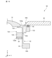
- FIG. 2 is a cross-sectional view showing an imaging device provided with the vibrating device of FIG. 1;
- FIG. 4 is a diagram showing simulation results of displacement amount distribution in the vibrating device of Embodiment 1.
- FIG. Graph showing the width dependence of the displacement amount of the stretched part Graph showing the thickness dependence of the displacement amount of the stretched part 4 is a partial cross-sectional view showing a vibrating device according to Modification 1 of Embodiment 1.
- FIG. FIG. 4 is a partial cross-sectional view showing a vibrating device according to Modification 2 of Embodiment 1;
- FIG. 4 is a partial cross-sectional view showing a vibrating device according to Modification 3 of Embodiment 1; Partial cross-sectional view showing a vibrating device according to a second embodiment The figure which shows the simulation result of displacement amount distribution in the vibration apparatus of FIG. Diagram showing the results of resonance analysis of the vibrating body of the vibrating device Diagram showing the results of resonance analysis of the vibrating body of the vibrating device Graph showing width dependence of weight displacement Graph showing thickness dependence of weight displacement
- FIG. 4 is a partial cross-sectional view showing a vibrating device according to Modification 1 of Embodiment 2; FIG.
- FIG. 4 is a partial cross-sectional view showing a vibrating device according to Modification 2 of Embodiment 2;
- FIG. 10 is a diagram showing simulation results of displacement amount distribution in the vibrating device of Embodiment 3; Partial cross-sectional view showing a vibrating device according to Modification 1 of Embodiment 3
- FIG. 11 is a partial cross-sectional view showing a vibrating device according to Modification 2 of Embodiment 3;
- FIG. 11 is a partial cross-sectional view showing a vibrating device according to Modification 3 of Embodiment 3;
- FIG. 11 is a partial cross-sectional view showing a vibrating device according to Modification 4 of Embodiment 3; Sectional drawing which shows the vibration apparatus concerning Embodiment 4 Partial cross-sectional view showing a vibrating device according to Modification 1 of Embodiment 4
- Cameras used outdoors such as in-vehicle cameras, surveillance cameras, and cameras mounted on drones, are provided with a cover formed of glass, transparent plastic, or the like so as to cover the lens because it is exposed to the elements. If foreign matter such as water droplets adheres to the cover, the foreign matter may be reflected in the image captured by the camera, obstructing the field of view of the camera and making it impossible to obtain a clear image.
- the drip-proof cover is flexurally vibrated to miniaturize foreign matter such as water droplets adhering to the drip-proof cover. and an apparatus for removing by atomization are being studied.
- the piezoelectric element is fixedly attached to the flange portion of the drip-proof cover. Therefore, the vibration of the piezoelectric element also vibrates the flange portion of the drip-proof cover outside the field of view of the imaging device. That is, there is a problem that the vibration of the piezoelectric element escapes to the flange portion of the drip-proof cover, making it difficult to vibrate the drip-proof cover efficiently.
- the present inventors (and others) have studied a vibrating device capable of vibrating a translucent body efficiently, and have arrived at the following invention.
- the vibration device includes: a translucent body; a cylindrical member having one end, the other end, and a side wall connecting the one end and the other end, wherein the vibrating body is connected to the translucent body at the one end and vibrates the translucent body; an extension extending outward from the side wall of the vibrating body; a piezoelectric element arranged at the other end of the vibrating body; Prepare.
- the extending portion may be bent toward the one end side or the other end side.
- the extending portion may extend outward on the one end side of the vibrating body.
- the extended portion becomes a vibration node, and the vibration efficiency can be further improved.
- the extending portion may extend outward from the one end of the vibrating body.
- the extended portion becomes a vibration node, so even if foreign matter such as water droplets adheres, the vibration performance is less likely to be affected.
- a vibration device includes: moreover, a tubular first member arranged on the one end side of the vibrating body and attached to the side wall of the vibrating body; and the vibrating body of the translucent body extending inward from an inner surface of the first member a retainer having a second member in contact with the surface connecting to and the opposite surface; with The extension portion may be provided so as to extend outward from the outer surface of the first member of the retainer.
- the translucent body can be firmly held, and the reliability of the vibrating device can be improved.
- One or a plurality of weights may be arranged on at least one of the first surface on the one end side and the second surface on the other end side of the extending portion.
- the weighted portion in addition to the extended portion becomes a vibration node, so the vibration efficiency can be further improved.
- the plurality of weights may be arranged at equal intervals on the extending portion when viewed from the axial direction of the vibrating body.
- the vibration efficiency of the vibration device can be further improved.
- a vibration device includes: a cover formed with a hole exposing the translucent body, disposed outside the translucent body and attached to the extension to contact the surface of the one weight;
- the one weight is annularly formed, Said one weight may have a sealing member arranged in a groove provided in said surface.
- An end portion of the cover on the side of the hole may be formed in a tapered shape in which the thickness decreases toward the transparent body.
- the vibrating body has a first protrusion that protrudes inward from the one end and a second protrusion that protrudes inward from the other end
- the vibrating device may further include a holding portion connected to the second projecting portion and holding the vibrating body.
- the second projecting portion of the vibrating body serves as a node, so the holding portion can be connected to the vibrating device without affecting the vibration performance.
- the effective volume of the vibrating device can be reduced, and a compact vibrating device can be realized.
- An imaging device comprises Any vibration device as described above; an imaging device arranged inside the vibrating device; Prepare.
- FIG. 1 is a cross-sectional view showing a vibration device 1 according to Embodiment 1.
- FIG. 1 is a cross-sectional view showing a vibration device 1 according to Embodiment 1.
- the vibrating device 1 includes a translucent body 10, a vibrating body 20, an extending portion 21, and a piezoelectric element 30.
- the vibrating device 1 can be used as an imaging device by housing an imaging device inside.
- the vibrating device 1 transmits the vibration of the piezoelectric element 30 arranged on the vibrating body 20 to the translucent body 10 via the vibrating body 20 to vibrate the translucent body 10 , thereby vibrating the water droplets or mud adhering to the translucent body 10 . It is a device that removes foreign matter such as A conductor (not shown) that applies a potential to the piezoelectric element 30 may be arranged in the vibrating device 1 .
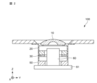
- FIG. 2 is a cross-sectional view showing an imaging device 100 including the vibrating device 1 of FIG.
- the vibrating device 1 can be used as an imaging device 100 by housing an imaging element 60 inside.
- the imaging device 100 includes the vibrating device 1 and the imaging device 60 .
- the imaging element 60 is connected to, for example, a substrate 61 or the like.
- the imaging element 60 can capture an image of an object to be imaged outside the vibration device 1 through the transparent body 10 of the vibration device 1 .
- the vibrating device 1 is fixed to the substrate 61 via the holding portion 50 .
- the translucent body 10 functions as a cover for protecting the imaging device accommodated in the vibrating device 1 from adhesion of foreign substances.
- Translucent body 10 may also function as an optically designed lens.
- the translucent body 10 has a translucency through which an energy ray or light having a wavelength detected by an imaging device is transmitted. In this embodiment, as shown in FIG. 1, the translucent body 10 is formed in a dome shape.
- the translucent body 10 for example, glass such as soda glass, borosilicate glass, aluminosilicate glass, or quartz glass, translucent plastic, translucent ceramics, synthetic resin, or the like can be used. .
- the strength of the translucent body 10 can be increased by forming the translucent body 10 from, for example, tempered glass whose strength is improved by chemical strengthening or the like.
- the vibrating body 20 receives the vibration of the piezoelectric element 30 and vibrates the translucent body 10 .
- the vibrating body 20 is a tubular member having one end 20a, the other end 20b, and a side wall 20c connecting the one end 20a and the other end 20b, as shown in FIG.
- One end of the vibrating body 20 is connected to the translucent body 10 .
- the translucent body 10 and the vibrating body 20 can be connected by, for example, an adhesive.
- one end 20a of the vibrating body 20 is formed with a recess 20d for disposing the translucent body 10 thereon.
- one end 20a of the vibrating body 20 may be formed flat, and the translucent body 10 may be fixed to the one end 20a with an adhesive or the like.
- the vibrating body 20 has a first protruding portion 24 protruding inward from one end 20a and a second protruding portion 25 protruding inward from the other end 20b. Since the vibrating body 20 has such a shape, a part of the extended portion 21 and the second protruding portion 25 becomes a node with a small amount of displacement of the vibrating body 20 due to vibration.
- the material of the vibrating body 20 for example, metal, ceramics, or the like can be used.
- metals that can be used include stainless steel, 42 alloy, 50 alloy, invar, super invar, kovar, aluminum, and duralumin.
- it may be made of ceramics such as alumina and zirconia.
- the vibrating body 20 may be made of a semiconductor such as Si. Also, the vibrating body 20 may be subjected to an insulating coating such as alumite treatment.
- the extending portion 21 extends outward from the side wall 20c of the vibrating body 20, as shown in FIG.
- the vibrating body 20 is formed so as to extend outward from one end 20a.
- the extending portion 21 is a portion that becomes a node where the amount of displacement due to vibration is 0 when the vibrating body 20 is vibrating. Since the extending portion 21 serves as a vibration node, the vibration of the vibrating body 20 can be efficiently transmitted to the transparent body 10 without escaping to the extending portion 21 . Moreover, even if foreign matter such as water droplets or mud adheres to the extending portion 21, the influence on the vibration performance of the vibrating body 20 can be reduced.
- the extending portion 21 is a flange formed on the side wall of the vibrating body 20 on the one end 20a side. Therefore, the extending portion 21 has a ring-like shape when viewed from the axial direction (Z direction) of the vibrating body 20 . Further, the extending portion 21 and the vibrating body 20 are integrally formed. The extending portion 21 is formed in a plate shape having a first surface 21a on the one end 20a side of the vibrating body 20 and a second surface 21b on the other end 20b side of the vibrating body 20 .
- the thickness t1 of the extended portion 21 is preferably 0.25 mm or more and 1 mm or less, for example. More preferably, the thickness t1 of the extended portion 21 is 0.5 mm. In this case, the displacement amount of the extending portion 21 can be reduced, and the vibration of the vibrating body 20 can be efficiently transmitted to the translucent body 10 .
- the width w1 of the extended portion 21 is preferably 4 mm or more and 6 mm or less, for example. More preferably, the width w1 of the extended portion 21 is 4.6 mm. In this case, the displacement amount of the extending portion 21 can be reduced, and the vibration of the vibrating body 20 can be efficiently transmitted to the translucent body 10 .
- the width w1 of the extending portion 21 indicates the length of the extending portion 21 protruding from the side wall 20c of the vibrating body 20. As shown in FIG.
- the extending portion 21 is provided in a direction orthogonal to the axial direction (Z direction) of the vibrating body 20 from one end 20a of the vibrating body. That is, the extending portion 121 is formed such that the one end 20a of the vibrating body 20 and the first surface 21a of the extending portion 21 are substantially at the same height in the axial direction of the vibrating body 20 .
- the extending portion 21 and the one end 20a of the vibrating body 20 are formed at substantially the same height, the amount of displacement due to vibration of the extending portion 21 can be reduced, and the vibration performance of the vibrating device 1 can be improved.
- the piezoelectric element 30 is arranged at the other end 20 b of the vibrating body 20 .
- the piezoelectric element 30 is formed in a ring shape when viewed from the axial direction (Z direction) of the vibrating body 20 .
- the piezoelectric element 30 can be fixed to the other end 20b of the vibrating body 20 with an adhesive, for example.
- the shape of the piezoelectric element 30 is not limited to a ring shape, and may be any shape that allows the vibrating body 20 to vibrate.
- the piezoelectric element 30 has a piezoelectric body and electrodes.
- materials that form the piezoelectric body include barium titanate (BaTiO 3 ), lead zirconate titanate (PZT: PbTiO 3 .PbZrO 3 ), lead titanate (PbTiO 3 ), and lead metaniobate (PbNb 2 O). 6 ), appropriate piezoelectric ceramics such as bismuth titanate ( Bi4Ti3O12 ) and (K, Na) NbO3 , or appropriate piezoelectric single crystals such as LiTaO3 and LiNbO3 can be used.
- the electrodes may be Ni electrodes, for example.
- the electrode may be an electrode made of a metal thin film such as Ag or Au, which is formed by a sputtering method.
- the electrodes can be formed by plating or vapor deposition in addition to the sputtering method.
- the piezoelectric element 30 is controlled by, for example, a control unit.
- the control unit has, for example, an excitation circuit for applying a drive signal to generate vibrations.
- the excitation circuit is connected to the piezoelectric element 30 via, for example, a power supply conductor.
- the piezoelectric element 30 vibrates the vibrating body 20 in the thickness direction (Z direction) of the vibrating device 1 based on the drive signal from the excitation circuit.
- the piezoelectric element 30 vibrates, the vibrating body 20 vibrates in the thickness direction (Z direction).
- the translucent body 10 is vibrated by vibrating the vibrating body 20 , and foreign matter such as water droplets adhering to the translucent body 10 is removed.
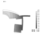
- FIG. 3 is a diagram showing a simulation result of the displacement amount distribution in the vibration device 1 of Embodiment 1.
- FIG. 3 For the simulation, Femtet manufactured by Murata Software Co., Ltd. was used to perform piezoelectric analysis (resonance analysis).
- the calculation conditions for the simulation of FIG. 3 are as follows.
- the material of the transparent body 10 corresponds to soda glass with a density of 2.48 g/cm 3 and a Young's modulus of 73 GPa.
- the diameter of the translucent body 10 is 14 mm.
- the material of the vibrating body 20 corresponds to SUS420J2 with a density of 7.75 g/cm 3 and a Young's modulus of 200 GPa.
- the piezoelectric element 30 has a density of 7.83 g/cm 3 , and a voltage of 60 Vp-p is applied to the upper and lower surfaces of the piezoelectric element 30 (the surface in contact with the vibrating body 20 and the surface on the opposite side).
- the piezoelectric element has an outer diameter of 16 mm, an inner diameter of 10 mm, and a thickness of 1 mm. In FIG. 12, the lighter the color, the greater the amount of displacement.
- the extension portion 21 has a displacement amount close to 0 and hardly vibrates. This indicates that the extension 21 is a vibration node.
- the amount of displacement is the largest near the center of the translucent body 10 . From this, it can be seen that the vibration of the vibrating body 20 is suppressed from escaping to the extending portion 21 and is transmitted to the translucent body 10 . Therefore, foreign matter such as water droplets or mud adhering to the translucent body 10 can be efficiently removed.
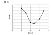
- FIG. 4A is a graph showing the width dependence of the amount of displacement of the extending portion 21.
- FIG. FIG. 4B is a graph showing thickness dependence of the amount of displacement of the extending portion 21 .
- FIG. 4A shows the dependence of the amount of displacement of the extending portion 21 on the width w1 (see FIG. 1) when the thickness t1 (see FIG. 1) of the extending portion 21 is fixed at 0.5 mm.
- FIG. 4B shows the dependence of the amount of displacement of the extending portion 21 on the thickness t1 when the width w1 of the extending portion 21 is fixed at 4.6 mm.
- the displacement amount in the graphs of FIGS. 4A and 4B was calculated as the maximum displacement amount of the extending portion 21 .
- the width w1 of the extending portion 21 is 4 mm or more and 6 mm or less, the amount of displacement of the extending portion 21 can be kept small. Therefore, the width w1 of the extending portion 21 is preferably 4 mm or more and 6 mm or less. Further, when the width w1 of the extended portion 21 was 4.6 mm, the amount of displacement of the extended portion 121 was the smallest. Therefore, more preferably, the width w1 of the extended portion 121 is 4.6 mm.
- the thickness t1 of the extended portion 21 is 0.25 mm or more and 1 mm or less, the amount of displacement of the extending portion 21 can be kept small. Therefore, the thickness t1 of the extended portion 21 is preferably 0.25 mm or more and 1 mm or less. Further, when the thickness t1 of the extended portion 21 was 0.5 mm, the amount of displacement of the extended portion 21 was the smallest. Therefore, more preferably, the thickness t1 of the extended portion 21 is 0.5 mm.
- the vibrating device 1 includes a translucent body 10, a vibrating body 20, an extending portion 21, and a piezoelectric element 30.
- the vibrating body 20 is a cylindrical member having one end 20a, the other end 20b, and a side wall 20c connecting the one end 20a and the other end 20b. to vibrate.
- the extending portion 21 extends outward from the side wall 20c of the vibrating body 20 .
- the piezoelectric element 30 is arranged at the other end 20 b of the vibrating body 20 .
- the extending portion 21 becomes a vibration node, the translucent body 10 can be vibrated efficiently. Further, even if a foreign substance such as a water droplet adheres to the extending portion 21, since the extending portion 21 is a vibration node, the influence on the vibration of the translucent body 10 can be reduced. Further, even if there are manufacturing variations, by forming the nodes in the extending portions 21, the vibration can be efficiently transmitted to the translucent body 10.
- the extending portion 21 extends outward from one end 20a of the vibrating body 20 . With such a configuration, it is possible to reduce the amount of displacement caused by the vibration of the extending portion 21 and improve the vibration performance of the vibrating device 1 .
- the extending portion 21 is ring-shaped has been described, but the shape of the extending portion 21 is not limited to this.
- the extending portion 21 may have any shape as long as it extends outward from the side wall 20c of the vibrating body 20 .
- the imaging device 100 includes a vibrating device 1 and an imaging element 60 arranged inside the vibrating device 1 .
- FIG. 5 is a partial cross-sectional view showing a vibration device 1A according to Modification 1 of Embodiment 1.
- the extending portion 121 may be bent toward the other end 120b of the vibrating body 120.
- the vibrating body 120 may be formed in a cylindrical shape without the first protrusion and the second protrusion.
- the translucent body 110 may be formed in a plate shape. In this case, the same effects as in the first embodiment can be obtained with a simple configuration.
- FIG. 6 is a partial cross-sectional view showing a vibration device 1B according to Modification 2 of Embodiment 1.
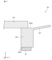
- FIG. 6 the extending portion 221 may be bent toward the one end 220a of the vibrating body 220. As shown in FIG. In this case, the same effects as in the first embodiment can be obtained with a simple configuration.
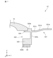
- FIG. 7 is a partial cross-sectional view showing a vibration device 1C according to Modification 3 of Embodiment 1.
- the extending portion 321 may be formed extending outward from the one end 320a side of the vibrating body 320 .
- the extending portion 321 extends outward from the side wall 320c on the one end 320a side of the vibrating body 320.
- the extending portion 321 is composed of a first portion 321c, a second portion 321d, and a third portion 321e.
- the first portion 321 c extends from the side wall 320 c of the vibrating body 320 in a direction orthogonal to the axial direction (Z direction) of the vibrating body 320 .
- the second portion 321d extends from the first portion 321c toward the one end 320a.
- the third portion 321e extends from the second portion 321d in a direction orthogonal to the axial direction (Z direction) of the vibrating body 320. As shown in FIG. Such a configuration facilitates the flow of water droplets or the like adhering to the extending portion 321 to the outside.
- the second portion 321d may extend from the first portion 321c toward the other end 320b.
- the vibrating body 320 has a first protruding portion 324 protruding inward from one end 320a and a second protruding portion 325 protruding inward from the other end 320b.
- the extended portion 321 and part of the second projecting portion 325 serve as vibration nodes. Therefore, a member such as a holding portion can be connected to the second projecting portion 325 without affecting the vibration of the translucent body 10 .
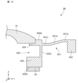
- FIG. 8 is a partial cross-sectional view showing the vibrating device 2 according to the second embodiment.
- the second embodiment differs from the first embodiment in that a weight 422 is arranged at the tip of the extending portion 421 .
- a weight 422 is arranged along the outer periphery of the second surface 421b of the extending portion 421.
- the weight 422 is formed in a ring shape along the outer periphery of the second surface 421b of the extending portion 421.
- the weight can be made of the same material as the extension 421, for example.
- the extending portion 421 and the weight 422 are integrally formed, but the extending portion 21 and the weight 422 may be formed of separate members. In that case, a weight 422 made of another member may be attached to the extension portion 421 .
- the weight 422 By arranging the weight 422 on the extending portion 421 , the amount of displacement of the extending portion 421 can be further reduced, and the vibration of the vibrating body 420 can be efficiently transmitted to the translucent body 10 .
- the amount of displacement of the extending portion 421 By arranging a weight 422 on the extending portion 421 formed in a plate shape to add weight, the amount of displacement of the extending portion 421 can be reduced. As a result, the vibration performance of the vibration device 2 can be improved.
- the vibrating device 2 has a configuration in which a weight 422 is arranged on an extending portion 421 extending from one end 420a of a vibrating body 420.
- FIG. 9A is a diagram showing a simulation result of displacement amount distribution in the vibration device 2 of FIG.
- Femtet manufactured by Murata Software Co., Ltd. was used to perform piezoelectric analysis (resonance analysis).
- the calculation conditions for the simulation of FIG. 9A are as follows.
- the material of the transparent body 10 corresponds to soda glass with a density of 2.48 g/cm 3 and a Young's modulus of 73 GPa.
- the diameter of the translucent body 10 is 14 mm.
- the material of the vibrating body 420 corresponds to SUS420J2 with a density of 7.75 g/cm 3 and a Young's modulus of 200 GPa.
- the piezoelectric element 30 has a density of 7.83 g/cm 3 , and a voltage of 60 Vp-p is applied to the upper and lower surfaces of the piezoelectric element 30 (the surface in contact with the vibrating body 420 and the surface on the opposite side).
- the piezoelectric element 30 has an outer diameter of 16 mm, an inner diameter of 10 mm, and a thickness of 1 mm. In FIG. 9A, the lighter the color, the greater the amount of displacement.
- the extending portion 421 and the weight 422 are vibration nodes. Further, by disposing the weight 422 on the extending portion 421, the amount of displacement of the extending portion 421 can be further reduced as compared with the case where the extending portion 421 has no weight.
- the weight 422 serves as a vibration node, so that the vibration of the vibrating body 420 can be transmitted to the translucent body 10 more efficiently.
- the weight 422 also serves as a vibration node, even if a foreign object adheres to the weight 422, the vibration performance of the vibrating device 2 can be maintained without affecting the vibration.
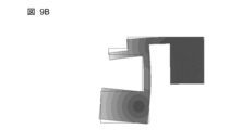
- FIG. 9B and 9C are diagrams showing resonance analysis results of the vibrating body 420 of the vibrating device 2.
- FIG. FIG. 9B shows the case when the phase is 0°
- FIG. 9C shows the case when the phase is 180°.
- the vibrating body 420 vibrates in a tuning fork resonance mode.
- two nodes are formed in the vibrating body 420 symmetrically about an intermediate position in1 (see FIG. 8) between the first projecting portion 424 and the second projecting portion 425 .
- One of the two nodes is the extension 421 and the weight 422 and the other node is part of the second protrusion 425 .
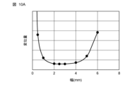
- FIG. 10A is a graph showing the width dependence of the displacement amount of the weight 422.
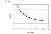
- FIG. 10B is a graph showing the thickness dependence of the amount of displacement of the weight 422 .
- FIG. 10A shows the dependence on the width w2 (see FIG. 8) of the weight 422 when the thickness t2 (see FIG. 8) of the weight 422 is fixed at 3.5 mm.
- FIG. 10B shows the dependence on the thickness t2 of the weight 422 when the width w2 of the weight 422 is fixed at 2.5 mm.
- the width w2 of the weight 422 is the length of the weight 422 in the outward direction from the side wall 420c of the vibrating body 420.
- the thickness t2 of the weight 422 is the length from the first surface 421a of the extending portion 421 to the lower end 422a (see FIG. 8) of the weight 422.
- FIG. 10A shows the width w2 (see FIG. 8) of the weight 422 when the thickness t2 (see
- the width w2 of the weight 422 is 1 mm or more and 5 mm or less, the amount of displacement of the weight 422 can be kept small. Therefore, the width w2 of the weight 422 is preferably 1 mm or more and 5 mm or less. Moreover, when the width w2 of the weight 422 was 2.5 mm, the amount of displacement of the weight 422 was the smallest. Therefore, more preferably, the width w2 of the weight 422 is 2.5 m.
- the thickness t2 of the weight 422 can be set to an arbitrary value depending on the trade-off between the size of the vibration device 2 and the vibration performance.
- a weight 422 is arranged on the second surface 421b of the extending portion 421 on the side of the other end 420b of the vibrating body 420.
- the weight 422 By arranging the weight 422 on the extending portion 421, it becomes easier to form a vibration node in the extending portion 421, so that the vibration of the vibrating body 420 can be transmitted to the translucent body 10 more efficiently.
- the weight 422 also serves as a vibration node, even if a foreign object adheres to the weight 422, the vibration performance of the vibrating device 2 can be maintained without affecting the vibration.
- the weight 422 is arranged on the second surface 421b of the extending portion 421 , but the present invention is not limited to this.
- the weight 422 may be arranged on either the first surface 421a on the one end 420a side of the vibrating body 520 or the second surface 421b on the other end 420b side.
- weight 422 is arranged on the extending portion 421
- the present invention is not limited to this.
- a plurality of weights may be arranged on either the first surface 421 a or the second surface 421 b of the extension portion 421 . In this case, each weight should be arranged at regular intervals.
- FIG. 11 is a partial cross-sectional view showing a vibration device 2A according to Modification 1 of Embodiment 2. As shown in FIG. As shown in FIG. 11 , the weight 522 may be arranged at a position other than the tip of the extension portion 521 . Even in such a configuration, the same effects as in the second embodiment can be obtained.
- FIG. 12 is a partial cross-sectional view showing a vibration device 2B according to Modification 2 of Embodiment 2.
- the extending portion 621 may have a first portion 621c, a second portion 621d, and a third portion 621e, and the weight 622 may be arranged on the third portion 621e.
- Such a configuration makes it easier for water droplets or the like adhering to the extending portion 621 to flow to the outside.
- FIG. 3 A vibrating device 3 according to a third embodiment of the present invention will be described. Note that in the third embodiment, differences from the second embodiment will be mainly described. In the third embodiment, the same reference numerals are assigned to the same or equivalent configurations as in the second embodiment. Moreover, in the third embodiment, the description overlapping with that in the second embodiment is omitted.
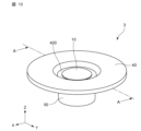
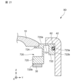
- FIG. 13 is a perspective view showing the vibrating device 3 according to the third embodiment.
- FIG. 14 is an exploded view of the vibration device 3 of FIG.
- FIG. 15 is a cross-sectional view of the vibrating device 3 of FIG. 13 taken along the line AA.
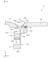
- FIG. 16 is an enlarged view of part of the vibration device 3 of FIG.
- a vibrating device 3 according to the third embodiment differs from the second embodiment in that it includes a cover 40 and a holding portion 50, as shown in FIGS. Further, the vibrating device 3 according to the third embodiment differs from the second embodiment in that a groove 723 is formed in the weight 722 and the seal member 62 is arranged in the groove 723 .
- a groove 723 is formed on the surface of the weight 722 (the first surface 721a of the extending portion 721).
- the groove 723 is formed in a ring shape along the outer circumference of the weight 722 when viewed from the axial direction (Z direction) of the vibrating body 720 .
- a seal member 62 is arranged in the groove 723 .
- the seal member 62 is an elastic member such as an O-ring.
- the cover 40 is a member that prevents foreign matter from entering the vibrating device 3 .
- the cover 40 is formed with a hole 40a through which the translucent body 10 is exposed.
- the cover 40 is arranged outside the translucent body 10 and attached to the extending portion 721 to contact the surface of the weight 722 .
- the cover 40 is formed in a plate shape having holes 40a.
- the vibrating device 3 can have a waterproof structure.
- the end 40b of the cover 40 on the side of the hole 40a is tapered so that the thickness decreases toward the translucent body 10. As shown in FIG.
- the vibrating device 3 can be covered without impairing the viewing angle of the imaging element, and both performance and reliability of the vibrating device 2 can be achieved. be able to.
- FIG. 17 is a diagram showing a simulation result of the displacement amount distribution in the vibration device 3 of Embodiment 3.
- FIG. 17 For the simulation, Femtet manufactured by Murata Software Co., Ltd. was used to perform piezoelectric analysis (resonance analysis).
- the calculation conditions for the simulation of FIG. 17 are as follows.
- the material of the transparent body 10 corresponds to soda glass with a density of 2.48 g/cm 3 and a Young's modulus of 73 GPa.
- the diameter of the translucent body 10 is 14 mm.
- the material of the vibrating body 20 corresponds to SUS420J2 with a density of 7.75 g/cm 3 and a Young's modulus of 200 GPa.
- the piezoelectric element 30 has a density of 7.83 g/cm 3 , and a voltage of 60 Vp-p is applied to the upper and lower surfaces of the piezoelectric element 30 (the surface in contact with the vibrating body 20 and the surface on the opposite side).
- the piezoelectric element has an outer diameter of 16 mm, an inner diameter of 10 mm, and a thickness of 1 mm. In FIG. 17, the lighter the color, the greater the amount of displacement.
- the extension part 721 and the weight 722 have a displacement amount close to 0 and hardly vibrate.
- the amount of displacement is the largest near the center of the translucent body 10 . From this, it can be seen that the vibration of the vibrating body 20 is suppressed from escaping to the extending portion 721 and is transmitted to the translucent body 10 . Therefore, foreign substances such as water droplets adhering to the transparent body 10 can be efficiently removed.
- the extending portion 721 is a vibration node.
- the cover 40 since the cover 40 is brought into contact with the vibration node, a waterproof structure can be realized while maintaining the vibration performance of the vibrating device 3 .
- a part of the second projecting portion 725 of the vibrating body 720 also serves as a vibration node. Therefore, by connecting the holding portion 50 to a part of the second protruding portion 725 , it is possible to obtain a structure that holds the vibration device 3 while suppressing the influence on the vibration performance of the vibration device 3 .
- the vibrating device 3 further includes a cover 40 having a hole 40 a for exposing the translucent body 10 , arranged outside the translucent body 10 and attached to the extending portion 721 to contact one weight 722 .
- One weight 722 is formed in an annular shape.
- a seal member 62 is arranged in a groove 723 provided on the surface of one weight 722 .
- the end 40b of the cover 40 on the side of the hole 40a may be tapered so that the thickness decreases toward the translucent body 10 .
- the end portion 40b of the cover 40 can be shaped appropriately according to the viewing angle of the imaging element arranged inside the vibration device 3.
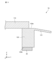
- FIG. 18 is a partial cross-sectional view showing a vibration device 3A according to Modification 1 of Embodiment 3.
- the holding portion 52 may have a base portion 53 projecting outward from the other end 52b.
- the vibrating device 3 can be stably arranged on a substrate or the like, and the reliability of the vibrating device 3 can be improved.
- FIG. 19 is a partial cross-sectional view showing a vibration device 3B according to Modification 2 of Embodiment 3.
- FIG. 19 the hole-side end 41b of the cover 41 may not be tapered.
- the end portion 41b of the cover 41 can be formed in an appropriate shape according to the viewing angle of the imaging device arranged inside the vibration device 3B.
- FIG. 20 is a partial cross-sectional view showing a vibration device 3C according to Modification 3 of Embodiment 3.
- FIG. 9 the cover 42 may be bent. By forming the cover 42 to be bent, the waterproof performance of the vibrating device 3C can be improved, and the reliability can be enhanced.
- FIG. 21 is a partial cross-sectional view showing a vibration device 3D according to Modification 4 of Embodiment 3.
- FIG. 21 a groove 723a may be formed in the side surface 722b of the weight 722, and the seal member 62 may be arranged in the groove 723a.
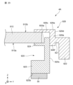
- FIG. 22 is a cross-sectional view showing a vibrating device 4 according to the fourth embodiment.
- the fourth embodiment differs from the first embodiment in that the vibrating device 4 includes a retainer 826 . Further, the fourth embodiment is different from the first embodiment in that the retainer 826 is provided with the extended portion 821 .
- the vibrating device 4 includes a retainer 826 arranged on the one end 820a side of the vibrating body 820 .
- the retainer 826 is a member for fixing the translucent body 810 to the vibrating body 820 .
- the transparent body 810 can be fixed by sandwiching the transparent body 810 between the retainer 826 and the vibrating body 820 .
- the retainer 826 has a first member 826a and a second member 826c.
- the first member 826 a is a tubular member attached to the side wall 820 c of the vibrating body 820 .
- the first member 826a extends inwardly from one end 826e of the retainer 826.
- the second member 826c extends inward from the inner surface 826b of the first member 826a and contacts the surface 810b opposite to the surface 810a of the translucent body 810 connected to the vibrating body.
- the extending portion 821 is provided at the other end 826f of the retainer 826 so as to extend outward from the outer surface 826d of the first member 826a.
- the other end 826f of the retainer 826 is located at substantially the same height as the one end 820a of the vibrating body 820 in the axial direction (Z direction) of the vibrating body 20. As shown in FIG. Therefore, in the axial direction (Z direction) of the vibrating body 820, the one end 820a of the vibrating body 820 and the extending portion 821 are arranged at substantially the same height.
- a weight 822 is provided at the tip of the extending portion 821 .
- the vibrating device 4 includes a retainer 826 arranged on the one end 820a side of the vibrating body 820 .
- the retainer 826 has a first member 826a and a second member 826c.
- the first member 826 a is a tubular member attached to the side wall 820 c of the vibrating body 820 .
- the second member 826c extends inward from the inner surface 826b of the first member 826a and contacts the surface 820b opposite to the surface 810a connected to the vibrating body 820 of the translucent body 810 .
- the extending portion 821 is provided extending outward from the outer surface 826d of the first member 826a of the retainer 826. As shown in FIG.
- the translucent body 810 can be firmly held, and the vibration of the vibrating body 820 can be efficiently transmitted to the translucent body 810 .
- FIG. 23 is a partial cross-sectional view showing a vibration device 4A according to Modification 1 of Embodiment 4.
- the extending portion 921 may be provided outward from an arbitrary position on the outer surface 926d of the first member 926a of the retainer 926.
- the extending portion 921 and the weight 922 serve as vibration nodes, and effects similar to those of the fourth embodiment can be obtained.
- the vibration device of the present invention can be applied to an on-vehicle camera used outdoors, a surveillance camera, or an optical sensor such as LiDAR.
Landscapes
- Engineering & Computer Science (AREA)
- Physics & Mathematics (AREA)
- Multimedia (AREA)
- Signal Processing (AREA)
- General Physics & Mathematics (AREA)
- Electromagnetism (AREA)
- Optics & Photonics (AREA)
- Mechanical Engineering (AREA)
- Camera Bodies And Camera Details Or Accessories (AREA)
Abstract
本発明の振動装置1は、透光体10と、一端20aと、他端20bと、一端20aおよび他端20bを繋ぐ側壁20cと、を有する筒状部材であり、一端20aで透光体10に接続し、透光体10を振動させる振動体20と、振動体20の側壁20cから外側に向かって延びる延伸部21と、振動体20の他端20bに配置された圧電素子30と、を備える。
Description
本発明は、振動装置および撮像装置に関する。
防滴カバーの光束通過領域に付着した液滴等を排除する液滴排除装置が知られている。
例えば、特許文献1には、光学素子のドーム部を形成する曲面の端部と接続し、ドーム部に屈曲振動を発生させる加振部材を具備する液滴排除装置が開示されている。特許文献1に記載の液滴排除装置では、加振部材を制御し、ドーム部に対して所定の振動を発生させて付着した液滴等を微小化して除去する。
特許文献1に記載の液滴排除装置は、ドーム部を効率よく振動させる点で未だ改善の余地がある。
そこで、本発明は、透光体を効率よく振動させることのできる振動装置を提供する。
本発明の一態様にかかる振動装置は、
透光体と、
一端と、他端と、前記一端および前記他端を繋ぐ側壁と、を有する筒状部材であり、前記一端で前記透光体に接続し、前記透光体を振動させる振動体と、
前記振動体の前記側壁から外側に向かって延びる延伸部と、
前記振動体の前記他端に配置された圧電素子と、
を備える。
透光体と、
一端と、他端と、前記一端および前記他端を繋ぐ側壁と、を有する筒状部材であり、前記一端で前記透光体に接続し、前記透光体を振動させる振動体と、
前記振動体の前記側壁から外側に向かって延びる延伸部と、
前記振動体の前記他端に配置された圧電素子と、
を備える。
本発明によると、透光体を効率よく振動させることのできる振動装置を提供することができる。
(本発明に至った経緯)
車載カメラや監視カメラ等、またはドローンに搭載されるカメラ等の屋外で使用するカメラには、風雨にさらされるためレンズを覆うようにガラスまたは透明プラスチック等で形成されるカバーが設けられている。カバーに水滴等の異物が付着すると、カメラにより撮像された画像に異物が映り込み、カメラの視界が遮られて鮮明な画像が得られない場合がある。
車載カメラや監視カメラ等、またはドローンに搭載されるカメラ等の屋外で使用するカメラには、風雨にさらされるためレンズを覆うようにガラスまたは透明プラスチック等で形成されるカバーが設けられている。カバーに水滴等の異物が付着すると、カメラにより撮像された画像に異物が映り込み、カメラの視界が遮られて鮮明な画像が得られない場合がある。
そこで、特許文献1に記載の液滴排除装置のように、防滴カバーに圧電体を配設することにより、防滴カバーを屈曲振動させて防滴カバーに付着した水滴等の異物を微小化および霧化して除去する装置が検討されている。
特許文献1に記載の液滴排除装置では、圧電素子が防滴カバーのフランジ部に接着固設されている。このため、圧電素子の振動により、撮像装置の視野外となる防滴カバーのフランジ部も振動してしまう。すなわち、圧電素子の振動が、防滴カバーのフランジ部に逃げてしまい、防滴カバーを効率よく振動させることが難しい、という課題がある。
また、液滴排除装置の製造ばらつきにより、圧電素子の振動を防滴カバーに効率よく伝達することができず、防滴カバーを効率よく振動させることが難しい、という課題がある。
本発明者(ら)は、透光体を効率よく振動させることのできる振動装置について検討し、以下の発明に至った。
本発明の第1態様にかかる振動装置は、
透光体と、
一端と、他端と、前記一端および前記他端を繋ぐ側壁と、を有する筒状部材であり、前記一端で前記透光体に接続し、前記透光体を振動させる振動体と、
前記振動体の前記側壁から外側に向かって延びる延伸部と、
前記振動体の前記他端に配置された圧電素子と、
を備える。
透光体と、
一端と、他端と、前記一端および前記他端を繋ぐ側壁と、を有する筒状部材であり、前記一端で前記透光体に接続し、前記透光体を振動させる振動体と、
前記振動体の前記側壁から外側に向かって延びる延伸部と、
前記振動体の前記他端に配置された圧電素子と、
を備える。
このような構成により、透光体を効率よく振動させることのできる振動装置を提供することができる。
本発明の第2態様にかかる振動装置において、
前記延伸部は、前記一端側または前記他端側に向かって屈曲していてもよい。
前記延伸部は、前記一端側または前記他端側に向かって屈曲していてもよい。
このような構成により、水滴等を外に流すためのガイドを形成することができ、効率的に水滴等を排除することができる。
本発明の第3態様にかかる振動装置において、
前記延伸部は、前記振動体の前記一端側で外側に向かって延びてもよい。
前記延伸部は、前記振動体の前記一端側で外側に向かって延びてもよい。
このような構成により、延伸部が振動のノードとなり、さらに振動効率を向上させることができる。
本発明の第4態様にかかる振動装置において、
前記延伸部は、前記振動体の前記一端から外側に向かって延びてもよい。
前記延伸部は、前記振動体の前記一端から外側に向かって延びてもよい。
このような構成により、延伸部が振動のノードとなるため、水滴等の異物が付着しても振動性能に影響を与えにくい。
本発明の第5態様にかかる振動装置は、
さらに、
前記振動体の前記一端側に配置され、前記振動体の前記側壁に取り付けられる筒状の第1部材と、前記第1部材の内側面から内側に向かって延びて前記透光体の前記振動体と接続する面と反対側の面に接触する第2部材と、を有するリテーナー、
を備え、
前記延伸部は、前記リテーナーの前記第1部材の外側面から外側に向かって延びて設けられていてもよい。
さらに、
前記振動体の前記一端側に配置され、前記振動体の前記側壁に取り付けられる筒状の第1部材と、前記第1部材の内側面から内側に向かって延びて前記透光体の前記振動体と接続する面と反対側の面に接触する第2部材と、を有するリテーナー、
を備え、
前記延伸部は、前記リテーナーの前記第1部材の外側面から外側に向かって延びて設けられていてもよい。
このような構成により、透光体を強固に保持することができ、振動装置の信頼性を向上させることができる。
本発明の第6態様にかかる振動装置において、
前記延伸部の、前記一端側の第1面または前記他端側の第2面の少なくともいずれか一方に、1つまたは複数の重りが配置されていてもよい。
前記延伸部の、前記一端側の第1面または前記他端側の第2面の少なくともいずれか一方に、1つまたは複数の重りが配置されていてもよい。
このような構成により、延伸部に加えて重りの部分も振動のノードとなるため、さらに振動効率を向上させることができる。
本発明の第7態様にかかる振動装置において、
前記複数の重りは、前記振動体の軸方向からみたときに、前記延伸部に等間隔に配置されていてもよい。
前記複数の重りは、前記振動体の軸方向からみたときに、前記延伸部に等間隔に配置されていてもよい。
このような構成により、振動装置の振動効率をさらに向上させることができる。
本発明の第8態様にかかる振動装置は、
さらに、前記透光体を露出する穴が形成され、前記透光体の外側に配置されて前記延伸部に取り付けられて前記1つの重りの表面に接触するカバー、を備え、
前記1つの重りは環状に形成され、
前記1つの重りには、前記表面に設けられた溝にシール部材が配置されていてもよい。
さらに、前記透光体を露出する穴が形成され、前記透光体の外側に配置されて前記延伸部に取り付けられて前記1つの重りの表面に接触するカバー、を備え、
前記1つの重りは環状に形成され、
前記1つの重りには、前記表面に設けられた溝にシール部材が配置されていてもよい。
このような構成により、振動装置の振動性能を維持しつつ、振動装置の内部に水滴等の異物が混入することを防ぎ、振動装置の信頼性、具体的には防水性能を向上させることができる。
本発明の第9態様にかかる振動装置において、
前記カバーの前記穴側の端部は、前記透光体に向かって厚みが小さくなるテーパー状に形成されていてもよい。
前記カバーの前記穴側の端部は、前記透光体に向かって厚みが小さくなるテーパー状に形成されていてもよい。
このような構成により、振動装置の性能向上と信頼性向上とを両立することができる。
本発明の第10態様にかかる振動装置において、
前記振動体は、前記一端から内側に突出する第1突出部と、前記他端から内側に突出する第2突出部と、を有し、
前記振動装置は、さらに、前記第2突出部に接続され、前記振動体を保持する保持部、を備えてもよい。
前記振動体は、前記一端から内側に突出する第1突出部と、前記他端から内側に突出する第2突出部と、を有し、
前記振動装置は、さらに、前記第2突出部に接続され、前記振動体を保持する保持部、を備えてもよい。
このような構成により、振動体の第2突出部がノードとなるため、振動性能に影響を与えずに振動装置に保持部を接続することができる。また、振動装置の有効体積を小さくすることができ、小型な振動装置を実現することができる。
本発明の第11態様にかかる撮像装置は、
上述のいずれかの振動装置と、
前記振動装置の内部に配置される撮像素子と、
を備える。
上述のいずれかの振動装置と、
前記振動装置の内部に配置される撮像素子と、
を備える。
このような構成により、信頼性の高い撮像装置を提供することができる。
以下、本発明の一実施形態を添付図面に従って説明する。なお、以下の説明は、本質的に例示に過ぎず、本発明、その適用物、あるいは、その用途を制限することを意図するものではない。さらに、図面は模式的なものであり、各寸法の比率等は現実のものとは必ずしも合致していない。
(実施の形態1)
[全体構成]
図1は、実施の形態1にかかる振動装置1を示す断面図である。
[全体構成]
図1は、実施の形態1にかかる振動装置1を示す断面図である。
図1に示すように、振動装置1は、透光体10と、振動体20と、延伸部21と、圧電素子30と、を備える。振動装置1は、内部に撮像素子を収容することで、撮像装置として使用することができる。
振動装置1は、振動体20に配置された圧電素子30による振動を、振動体20を介して透光体10に伝えて透光体10を振動させ、透光体10に付着した水滴または泥等の異物を除去する装置である。振動装置1には、圧電素子30に電位を与える図示省略の導体が配置されていてもよい。
図2は、図1の振動装置1を備える撮像装置100を示す断面図である。振動装置1は、図2に示すように、撮像素子60を内部に収容することで、撮像装置100として使用することができる。言い換えると、撮像装置100は、振動装置1と、撮像素子60と、を備える。撮像素子60は、例えば基板61などに接続される。撮像素子60により、振動装置1の透光体10を通して、振動装置1の外部の撮像対象物を撮像することができる。図2において、振動装置1は、保持部50を介して基板61に固定されている。
振動装置1を構成する各構成要素について、以下に詳細に説明する。
<透光体>
透光体10は、振動装置1に収容された撮像素子を異物の付着から保護するためのカバーとして機能する。また、透光体10は、光学設計されたレンズとして機能することもある。透光体10は、撮像素子が検出する波長のエネルギー線または光が透過する透光性を有する。本実施の形態では、図1に示すように、本実施の形態では、透光体10はドーム状に形成されている。
透光体10は、振動装置1に収容された撮像素子を異物の付着から保護するためのカバーとして機能する。また、透光体10は、光学設計されたレンズとして機能することもある。透光体10は、撮像素子が検出する波長のエネルギー線または光が透過する透光性を有する。本実施の形態では、図1に示すように、本実施の形態では、透光体10はドーム状に形成されている。
透光体10の材料としては、例えば、ソーダガラス、ホウケイ酸ガラス、アルミノシリケートガラス、または石英ガラスなどのガラス、透光性のプラスチック、透光性のセラミックス、または合成樹脂等を用いることができる。透光体10を、例えば化学強化等で強度を向上させた強化ガラスにより形成することで、透光体10の強度を高めることができ
<振動体>
振動体20は、圧電素子30の振動を受けて、透光体10を振動させるものである。振動体20は、図1に示すように、一端20aと、他端20bと、一端20aおよび他端20bとを繋ぐ側壁20cと、を有する筒状部材である。振動体20の一端側で、透光体10に接続している。透光体10と振動体20とは、例えば、接着剤等により接続することができる。
振動体20は、圧電素子30の振動を受けて、透光体10を振動させるものである。振動体20は、図1に示すように、一端20aと、他端20bと、一端20aおよび他端20bとを繋ぐ側壁20cと、を有する筒状部材である。振動体20の一端側で、透光体10に接続している。透光体10と振動体20とは、例えば、接着剤等により接続することができる。
本実施の形態では、図1に示すように、振動体20の一端20aに、透光体10を配置するための凹部20dが形成されている。なお、振動体20の一端20aがフラットに形成され、透光体10が接着剤等により一端20aに固定されていてもよい。
本実施の形態では、振動体20は、一端20aから内側に突出する第1突出部24と、他端20bから内側に突出する第2突出部25と、を有する。振動体20がこのような形状を有することにより、延伸部21および第2突出部25の一部が振動による振動体20の変位量の小さいノードとなる。
振動体20の材料としては、例えば、金属またはセラミックス等を用いることができる。金属としては、例えば、ステンレス、42アロイ、50アロイ、インバー、スーパーインバー、コバール、アルミニウム、またはジュラルミン等を使用することができる。または、アルミナ、ジルコニアなどのセラミックスで形成されていてもよい。振動体20は、Siなどの半導体により形成されてもよい。また、振動体20は、アルマイト処理等の絶縁コーティングが施されていてもよい。
<延伸部>
延伸部21は、図1に示すように、振動体20の側壁20cから外側に向かって延びる。振動装置1では、振動体20の一端20aから外側に向かって延びて形成されている。延伸部21は、振動体20が振動しているときに、振動による変位量が0であるノードとなる部分である。延伸部21が振動のノードとなることで、振動体20の振動が延伸部21に逃げずに、振動を効率的に透光体10に伝えることができる。また、延伸部21に水滴または泥等の異物が付着しても、振動体20の振動性能への影響を低減することができる。
延伸部21は、図1に示すように、振動体20の側壁20cから外側に向かって延びる。振動装置1では、振動体20の一端20aから外側に向かって延びて形成されている。延伸部21は、振動体20が振動しているときに、振動による変位量が0であるノードとなる部分である。延伸部21が振動のノードとなることで、振動体20の振動が延伸部21に逃げずに、振動を効率的に透光体10に伝えることができる。また、延伸部21に水滴または泥等の異物が付着しても、振動体20の振動性能への影響を低減することができる。
本実施の形態では、延伸部21は、振動体20の一端20a側の側壁に形成されたフランジである。このため、延伸部21は、振動体20の軸方向(Z方向)から見たときに、リング状の形状を有する。また、延伸部21と振動体20とは一体的に形成されている。延伸部21は、振動体20の一端20a側の第1面21aと、振動体20の他端20b側の第2面21bとを有する板状に形成されている。
延伸部21の厚さt1は、例えば、0.25mm以上1mm以下であるとよい。より好ましくは、延伸部21の厚さt1は、0.5mmの厚さで形成されるとよい。この場合、延伸部21の変位量を小さくして、振動体20の振動を効率よく透光体10に伝達することができる。また、延伸部21の幅w1は、例えば、4mm以上6mm以下であるとよい。より好ましくは、延伸部21の幅w1は、4.6mmであるとよい。この場合、延伸部21の変位量を小さくして、振動体20の振動を効率よく透光体10に伝達することができる。なお、延伸部21の幅w1は、振動体20の側壁20cから突出した延伸部21の長さを示す。
また、本実施の形態では、延伸部21は、振動体の一端20aから振動体20の軸方向(Z方向)に直交する方向に設けられている。すなわち、振動体20の軸方向において、振動体20の一端20aと、延伸部21の第1面21aとが略同じ高さになるよう、延伸部121が形成されている。
延伸部21と振動体20の一端20aとが略同じ高さに形成されることで、延伸部21の振動による変位量を小さくして、振動装置1の振動性能を向上させることができる。
<圧電素子>
圧電素子30は、振動体20の他端20bに配置されている。本実施の形態では、圧電素子30は、振動体20の軸方向(Z方向)から見たときに、リング状に形成されている。圧電素子30は、例えば接着剤により、振動体20の他端20bに固定することができる。圧電素子30の形状は、リング状に限定されず、振動体20を振動させることのできる形状であればよい。
圧電素子30は、振動体20の他端20bに配置されている。本実施の形態では、圧電素子30は、振動体20の軸方向(Z方向)から見たときに、リング状に形成されている。圧電素子30は、例えば接着剤により、振動体20の他端20bに固定することができる。圧電素子30の形状は、リング状に限定されず、振動体20を振動させることのできる形状であればよい。
圧電素子30は、圧電体と、電極と、を有する。圧電体を形成する材料としては、例えば、チタン酸バリウム(BaTiO3)、チタン酸・ジルコン酸鉛(PZT:PbTiO3・PbZrO3)、チタン酸鉛(PbTiO3)、メタニオブ酸鉛(PbNb2O6)、チタン酸ビスマス(Bi4Ti3O12)、(K,Na)NbO3などの適宜の圧電セラミックス、またはLiTaO3、LiNbO3などの適宜の圧電単結晶などを用いることができる。
電極は、例えば、Ni電極であってもよい。電極は、スパッタリング法により形成される、AgまたはAuなどの金属薄膜からなる電極であってもよい。あるいは、電極はスパッタリング法の他、めっき、蒸着でも形成可能である。
圧電素子30は、例えば、制御部によって制御される。制御部は、例えば、振動を発生させる駆動信号を印加するための励振回路を有する。励振回路は、例えば、給電導体を介して圧電素子30と接続されている。圧電素子30は、励振回路からの駆動信号に基づいて、振動体20を振動装置1の厚さ方向(Z方向)に振動させる。圧電素子30が振動することによって、振動体20が厚さ方向(Z方向)に振動する。振動装置1では、振動体20を振動させることで透光体10が振動して、透光体10に付着した水滴等の異物が除去される。
図3は、実施の形態1の振動装置1における変位量分布のシミュレーション結果を示す図である。シミュレーションは、ムラタソフトウェア株式会社製のFemtetを用いて、圧電解析(共振解析)を行った。図3のシミュレーションの計算条件は次の通りである。透光体10の材料は、密度2.48g/cm3およびヤング率73GPaのソーダガラスに相当するものである。透光体10の直径は、14mmである。振動体20の材料は、密度7.75g/cm3およびヤング率200GPaのSUS420J2に相当するものである。圧電素子30は、密度が7.83g/cm3であり、圧電素子30の上下面(振動体20と接触する面、およびそれと反対側の面)に、60Vp-pの電圧を印加される。圧電素子は、外形16mm、内径10mm、および厚さ1mmである。図12において、色が薄くなるほど変位量が大きくなることを示す。
図3に示すように、延伸部21は変位量が0に近く、ほとんど振動していない。これは、延伸部21が振動のノードになっていることを示す。一方で、透光体10の中央付近が最も変位量が大きい。このことから、振動体20の振動が、延伸部21に逃げるのを抑制し透光体10に伝達されていることがわかる。このため、透光体10に付着した水滴または泥等の異物を効率的に除去することができる。
図4Aは、延伸部21の変位量の幅依存性を示すグラフである。図4Bは、延伸部21の変位量の厚さ依存性を示すグラフである。図4Aでは、延伸部21の厚さt1(図1参照)を0.5mmに固定した場合の、延伸部21の変位量の幅w1(図1参照)による依存性を示す。図4Bでは、延伸部21の幅w1を4.6mmに固定した場合の、延伸部21の変位量の厚さt1による依存性を示す。図4Aおよび図4Bのグラフにおける変位量は、延伸部21の最大の変位量を算出した。
図4Aに示すように、延伸部21の幅w1が4mm以上6mm以下の場合、延伸部21の変位量を小さく抑えることができる。したがって、延伸部21の幅w1は、4mm以上6mm以下であるとよい。また、延伸部21の幅w1が4.6mmである場合、延伸部121の変位量が最も小さくなった。したがって、より好ましくは、延伸部121の幅w1は4.6mmであるとよい。
図4Bに示すように、延伸部21の厚さt1が0.25mm以上1mm以下である場合、延伸部21の変位量を小さく抑えることができる。したがって、延伸部21の厚さt1は、0.25mm以上1mm以下であるとよい。また、延伸部21の厚さt1が0.5mmである場合、延伸部21の変位量が最も小さくなった。したがって、より好ましくは、延伸部21の厚さt1は0.5mmであるとよい。
[効果]
実施の形態1にかかる振動装置1によれば、以下の効果を奏することができる。
実施の形態1にかかる振動装置1によれば、以下の効果を奏することができる。
振動装置1は、透光体10と、振動体20と、延伸部21と、圧電素子30と、を備える。振動体20は、一端20aと、他端20bと、一端20aと他端20bとを繋ぐ側壁20cと、を有する筒状部材であり、一端20aで透光体10に接続し、透光体10を振動させる。延伸部21は、振動体20の側壁20cから外側に向かって延びる。圧電素子30は、振動体20の他端20bに配置される。
このような構成により、透光体10を効率よく振動させることのできる振動装置を提供することができる。延伸部21が振動のノードになることで、透光体10を効率的に振動させることができる。また、延伸部21に水滴等の異物が付着しても、延伸部21が振動のノードであるために、透光体10の振動への影響を低減することができる。また、製造ばらつきがあったとしても、延伸部21にノードを形成することで、透光体10に効率よく振動を伝えることができる。
延伸部21は、振動体20の一端20aから外側に向かって延びる。このような構成により、延伸部21の振動による変位量を小さくして、振動装置1の振動性能を向上させることができる。
なお、上述した実施の形態では、延伸部21がリング状である例について説明したが、延伸部21の形状はこれに限定されない。延伸部21は、振動体20の側壁20cから外側に向かって拡がる形状であればよい。
撮像装置100は、振動装置1と、振動装置1の内部に配置される撮像素子60と、を備える。
このような構成により、信頼性の高い撮像装置100を提供することができる。
[変形例]
図5は、実施の形態1の変形例1にかかる振動装置1Aを示す部分断面図である。図5に示すように、延伸部121が、振動体120の他端120b側に向かって屈曲していてもよい。また、振動体120が、第1突出部および第2突出部のない筒状に形成されていてもよい。さらに、透光体110が、板状に形成されていてもよい。この場合、簡素な構成で、実施の形態1と同様の効果を奏することができる。
図5は、実施の形態1の変形例1にかかる振動装置1Aを示す部分断面図である。図5に示すように、延伸部121が、振動体120の他端120b側に向かって屈曲していてもよい。また、振動体120が、第1突出部および第2突出部のない筒状に形成されていてもよい。さらに、透光体110が、板状に形成されていてもよい。この場合、簡素な構成で、実施の形態1と同様の効果を奏することができる。
図6は、実施の形態1の変形例2にかかる振動装置1Bを示す部分断面図である。図6に示すように、延伸部221が、振動体220の一端220a側に向かって屈曲していてもよい。この場合、簡素な構成で、実施の形態1と同様の効果を奏することができる。
図7は、実施の形態1の変形例3にかかる振動装置1Cを示す部分断面図である。図7に示すように、延伸部321が、振動体320の一端320a側から外側に向かって延びて形成されていてもよい。振動装置1Cにおいて、延伸部321は、振動体320の一端320a側の側壁320cから外側に向かって延びている。さらに、延伸部321は、第1部分321cと、第2部分321dと、第3部分321eと、により構成されている。第1部分321cは、振動体320の側壁320cから振動体320の軸方向(Z方向)と直交する方向に延びる。第2部分321dは、第1部分321cから一端320a側に向かって延びる。第3部分321eは、第2部分321dから振動体320の軸方向(Z方向)と直交する方向に延びる。このような構成により、延伸部321に付着した水滴等が外部に流れやすくなる。なお、第2部分321dは、第1部分321cから他端320b側に向かって延びていてもよい。
また、図7の振動装置1Cでは、振動体320が、一端320aから内側に突出する第1突出部324と、他端320bから内側に突出する第2突出部325と、を有する。振動装置1Cにおいて、延伸部321と第2突出部325の一部とが振動のノードとなる。このため、透光体10の振動に影響を与えずに、第2突出部325に保持部などの部材を接続することができる。
(実施の形態2)
本発明の実施の形態2にかかる振動装置について説明する。なお、実施の形態2では、主に実施の形態1と異なる点について説明する。実施の形態2においては、実施の形態1と同一または同等の構成については同じ符号を付して説明する。また、実施の形態2では、実施の形態1と重複する記載は省略する。
本発明の実施の形態2にかかる振動装置について説明する。なお、実施の形態2では、主に実施の形態1と異なる点について説明する。実施の形態2においては、実施の形態1と同一または同等の構成については同じ符号を付して説明する。また、実施の形態2では、実施の形態1と重複する記載は省略する。
図8は、実施の形態2にかかる振動装置2を示す部分断面図である。実施の形態2では、延伸部421の先端に重り422が配置されている点で、実施の形態1と異なる。
本実施の形態では、延伸部421の第2面421bの外周に沿って重り422が配置されている。重り422は、延伸部421の第2面421bの外周に沿ってリング状に形成されている。重りは、例えば、延伸部421と同じ材料で形成することができる。本実施の形態では、延伸部421と重り422とが一体的に形成されているが、延伸部21と重り422とが別の部材で形成されていてもよい。その場合、別の部材で形成された重り422が、延伸部421に貼り付けられていてもよい。
延伸部421に重り422が配置されることで、延伸部421の変位量をより低減させることができ、振動体420の振動を効率よく透光体10に伝達することができる。板状に形成された延伸部421に重り422を配置して重さを付加することで、延伸部421の変位量を小さくすることができる。その結果、振動装置2の振動性能を向上させることができる。
図8に示すように、振動装置2は、振動体420の一端420aから延びる延伸部421に、重り422が配置された構成である。図9Aは、図8の振動装置2における変位量分布のシミュレーション結果を示す図である。シミュレーションは、ムラタソフトウェア株式会社製のFemtetを用いて、圧電解析(共振解析)を行った。図9Aのシミュレーションの計算条件は次の通りである。透光体10の材料は、密度2.48g/cm3およびヤング率73GPaのソーダガラスに相当するものである。透光体10の直径は、14mmである。振動体420の材料は、密度7.75g/cm3およびヤング率200GPaのSUS420J2に相当するものである。圧電素子30は、密度が7.83g/cm3であり、圧電素子30の上下面(振動体420と接触する面、およびそれと反対側の面)に、60Vp-pの電圧を印加される。圧電素子30は、外形16mm、内径10mm、および厚さ1mmである。図9Aにおいて、色が薄くなるほど変位量が大きくなることを示す。
図9Aに示すように、振動装置2において、延伸部421および重り422は、振動のノードであることがわかる。また、延伸部421に重り422が配置されることにより、延伸部421に重りがない場合と比較して、延伸部421の変位量をさらに小さくすることができる。また、延伸部421に加えて、重り422が振動のノードとなるため、振動体420の振動を透光体10にさらに効率よく伝達することができる。また、重り422も振動のノードとなるため、重り422に異物が付着した場合でも、振動装置2の振動に影響を与えず振動性能を維持することができる。
図9Bおよび図9Cは、振動装置2の振動体420の共振解析結果を示す図である。図9Bは、位相が0°の場合を示し、図9Cは位相が180°の場合を示す。振動体420が第1突出部424および第2突出部425を有する構成の場合、振動体420は音叉の共振モードで振動する。この場合、第1突出部424と第2突出部425との中間位置in1(図8参照)を対称に、振動体420には2つのノードが形成される。2つのノードのうち一方のノードが、延伸部421および重り422であり、他方のノードが第2突出部425の一部である。
図10Aは、重り422の変位量の幅依存性を示すグラフである。図10Bは、重り422の変位量の厚さ依存性を示すグラフである。図10Aでは、重り422の厚さt2(図8参照)を3.5mmに固定した場合の、重り422の幅w2(図8参照)による依存性を示す。図10Bでは、重り422の幅w2を2.5mmに固定した場合の、重り422の厚さt2による依存性を示す。図10Aおよび図10Bのグラフにおける変位量は、重り422の最大の変位量を算出した。重り422の幅w2は、振動体420の側壁420cから外側に向かう方向における重り422の長さである。重り422の厚さt2は、延伸部421の第1面421aからの重り422の下端422a(図8参照)までの長さである。
図10Aに示すように、重り422の幅w2が1mm以上5mm以下の場合、重り422の変位量を小さく抑えることができる。したがって、重り422の幅w2は、1mm以上5mm以下であるとよい。また、重り422の幅w2が2.5mmである場合、重り422の変位量が最も小さくなった。したがって、より好ましくは、重り422の幅w2は2.5mであるとよい。
図10Bに示すように、重り422の厚さt2が大きくなるにつれて、重り422の変位量が小さくなる。したがって、重り422の厚さt2を大きくするほど、変位量を小さく抑えて良好なノードを形成することができる。したがって、重り422の厚さt2については、振動装置2の大きさと振動性能とのトレードオフにより、任意の値に設定することができる。
[効果]
実施の形態2にかかる振動装置2によれば、以下の効果を奏することができる。
実施の形態2にかかる振動装置2によれば、以下の効果を奏することができる。
振動装置2においては、延伸部421の、振動体420の他端420b側の第2面421bに、重り422が配置されている。
このような構成により、延伸部421に振動のノードを形成しやすくなるため、さらに振動効率を向上させることができる。
延伸部421に重り422が配置されることにより、延伸部421に振動のノードを形成しやすくなるため、振動体420の振動を透光体10にさらに効率よく伝達することができる。また、重り422も振動のノードとなるため、重り422に異物が付着した場合でも、振動装置2の振動に影響を与えず振動性能を維持することができる。
なお、上述した実施の形態では、延伸部421の第2面421bに重り422が配置されている例について説明したが、これに限定されない。重り422は、振動体520の一端420a側の第1面421aまたは他端420b側の第2面421bのいずれか一方に配置されていればよい。
また、上述した実施の形態では、延伸部421に1つの重り422が配置されている例について説明したが、これに限定されない。重りは、延伸部421の第1面421aまたは第2面421bのいずれか一方に複数配置されていてもよい。この場合、それぞれの重りは等間隔に配置されるとよい。
[変形例]
図11は、実施の形態2の変形例1にかかる振動装置2Aを示す部分断面図である。図11に示すように、重り522が延伸部521の先端以外の位置に配置されていてもよい。このような構成においても、実施の形態2と同様の効果を奏することができる。
図11は、実施の形態2の変形例1にかかる振動装置2Aを示す部分断面図である。図11に示すように、重り522が延伸部521の先端以外の位置に配置されていてもよい。このような構成においても、実施の形態2と同様の効果を奏することができる。
図12は、実施の形態2の変形例2にかかる振動装置2Bを示す部分断面図である。図12に示すように、延伸部621が、第1部分621cと、第2部分621dと、第3部分621e、を有する構成であり、第3部分621eに重り622が配置されていてもよい。このような構成により、延伸部621に付着した水滴等が外部に流れやすくなる。
(実施の形態3)
本発明の実施の形態3にかかる振動装置3について説明する。なお、実施の形態3では、主に実施の形態2と異なる点について説明する。実施の形態3においては、実施の形態2と同一または同等の構成については同じ符号を付して説明する。また、実施の形態3では、実施の形態2と重複する記載は省略する。
本発明の実施の形態3にかかる振動装置3について説明する。なお、実施の形態3では、主に実施の形態2と異なる点について説明する。実施の形態3においては、実施の形態2と同一または同等の構成については同じ符号を付して説明する。また、実施の形態3では、実施の形態2と重複する記載は省略する。
図13は、実施の形態3にかかる振動装置3を示す斜視図である。図14は、図13の振動装置3の分解図である。図15は、図13の振動装置3のA-A断面図である。図16は、図15の振動装置3の一部を拡大した図である。
実施の形態3にかかる振動装置3は、図13~図16に示すように、カバー40と、保持部50と、を備える点で実施の形態2と異なる。また、実施の形態3にかかる振動装置3は、重り722に溝723が形成され、溝723にシール部材62が配置されている点で、実施の形態2と異なる。
図16に示すように、重り722の表面(延伸部721の第1面721a)には、溝723が形成されている。溝723は、振動体720の軸方向(Z方向)から見たときに、重り722の外周に沿ってリング状に形成されている。溝723には、シール部材62が配置されている。シール部材62は、例えばOリングのような弾性部材である。
<カバー>
カバー40は、振動装置3の内部への異物の混入を防止する部材である。カバー40には、透光体10を露出する穴40aが形成されている。カバー40は、透光体10の外側に配置されて、延伸部721に取り付けられて重り722の表面に接触している。
カバー40は、振動装置3の内部への異物の混入を防止する部材である。カバー40には、透光体10を露出する穴40aが形成されている。カバー40は、透光体10の外側に配置されて、延伸部721に取り付けられて重り722の表面に接触している。
図14に示すように、本実施の形態では、カバー40は穴40aを有する板状に形成されている。本実施の形態では、カバー40を延伸部721に接触させることにより、振動装置3を防水構造とすることができる。
また、図16に示すように、カバー40の穴40a側の端部40bは、透光体10に向かって厚みが小さくなるテーパー状に形成されている。カバー40の端部40bがこのような形状に形成されることにより、撮像素子の視野角を損なうことなく、振動装置3をカバーすることができ、振動装置2の性能と信頼性とを両立することができる。
図17は、実施の形態3の振動装置3における変位量分布のシミュレーション結果を示す図である。シミュレーションは、ムラタソフトウェア株式会社製のFemtetを用いて、圧電解析(共振解析)を行った。図17のシミュレーションの計算条件は次の通りである。透光体10の材料は、密度2.48g/cm3およびヤング率73GPaのソーダガラスに相当するものである。透光体10の直径は、14mmである。振動体20の材料は、密度7.75g/cm3およびヤング率200GPaのSUS420J2に相当するものである。圧電素子30は、密度が7.83g/cm3であり、圧電素子30の上下面(振動体20と接触する面、およびそれと反対側の面)に、60Vp-pの電圧を印加される。圧電素子は、外形16mm、内径10mm、および厚さ1mmである。図17において、色が薄くなるほど変位量が大きくなることを示す。
図17に示すように、延伸部721および重り722は変位量が0に近く、ほとんど振動していない。一方で、透光体10の中央付近が最も変位量が大きい。このことから、振動体20の振動が、延伸部721に逃げるのを抑制し、透光体10に伝達されていることがわかる。このため、透光体10に付着した水滴等の異物を効率的に除去することができる。このように、延伸部721は、振動のノードになっている。本実施の形態では、振動のノードとなる部分にカバー40を接触させるため、振動装置3の振動性能を維持したまま防水構造を実現することができる。
また、図17によると、振動体720の第2突出部725の一部も振動のノードとなっている。このため、第2突出部725の一部に保持部50を接続することで、振動装置3の振動性能への影響を抑えつつ、振動装置3を保持する構造とすることができる。
[効果]
実施の形態3にかかる振動装置3によれば、以下の効果を奏することができる。
実施の形態3にかかる振動装置3によれば、以下の効果を奏することができる。
振動装置3は、さらに、透光体10を露出する穴40aが形成され、透光体10の外側に配置されて延伸部721に取り付けられて1つの重り722に接触するカバー40、を備える。1つの重り722は環状に形成される。1つの重り722には、表面に設けられた溝723にシール部材62が配置されている。
このような構成により、振動装置3の振動性能を維持しつつ、振動装置3の内部に水滴等の異物が混入することを防ぎ、振動装置3の信頼性、具体的には防水性能を向上させることができる。
カバー40の穴40a側の端部40bは、透光体10に向かって厚みが小さくなるテーパー状に形成されていてもよい。
振動装置3の内部に配置される撮像素子の視野角に応じて、カバー40の端部40bを適切な形状にすることができる。
[変形例]
図18は、実施の形態3の変形例1にかかる振動装置3Aを示す部分断面図である。図18に示すように、保持部52は、他端52bから外側に突出する土台部53を有していてもよい。この場合、振動装置3を基板等により安定して配置することができ、振動装置3の信頼性を向上させることができる。
図18は、実施の形態3の変形例1にかかる振動装置3Aを示す部分断面図である。図18に示すように、保持部52は、他端52bから外側に突出する土台部53を有していてもよい。この場合、振動装置3を基板等により安定して配置することができ、振動装置3の信頼性を向上させることができる。
図19は、実施の形態3の変形例2にかかる振動装置3Bを示す部分断面図である。図19に示すように、カバー41の穴側の端部41bがテーパー状に形成されていなくてもよい。振動装置3Bの内部に配置される撮像素子の視野角に応じて、カバー41の端部41bを適切な形状にすることができる。
図20は、実施の形態3の変形例3にかかる振動装置3Cを示す部分断面図である。図9に示すように、カバー42が屈曲して形成されていてもよい。カバー42が屈曲して形成されていることで、振動装置3Cの防水性能を向上させて、信頼性を高めることができる。
図21は、実施の形態3の変形例4にかかる振動装置3Dを示す部分断面図である。図21に示すように、重り722の側面722bに溝723aが形成され、溝723aにシール部材62が配置されていてもよい。
(実施の形態4)
本発明の実施の形態4にかかる振動装置について説明する。なお、実施の形態4では、主に実施の形態1と異なる点について説明する。実施の形態4においては、実施の形態1と同一または同等の構成については同じ符号を付して説明する。また、実施の形態4では、実施の形態1と重複する記載は省略する。
本発明の実施の形態4にかかる振動装置について説明する。なお、実施の形態4では、主に実施の形態1と異なる点について説明する。実施の形態4においては、実施の形態1と同一または同等の構成については同じ符号を付して説明する。また、実施の形態4では、実施の形態1と重複する記載は省略する。
図22は、実施の形態4にかかる振動装置4を示す断面図である。実施の形態4では、振動装置4がリテーナー826を備える点で、実施の形態1と異なる。また、実施の形態4では、リテーナー826に延伸部821が設けられている点で、実施の形態1と異なる。
図22に示すように、振動装置4は、振動体820の一端820a側に配置されるリテーナー826を備える。リテーナー826は、透光体810を振動体820に固定するための部材である。リテーナー826と振動体820とで、透光体810を挟むようにして、透光体810を固定することができる。
リテーナー826は、第1部材826aと、第2部材826cと、を有する。第1部材826aは、振動体820の側壁820cに取り付けられる筒状の部材である。本実施の形態では、第1部材826aはリテーナー826の一端826eから内側に延びて形成されている。第2部材826cは、第1部材826aの内側面826bから内側に向かって延びて透光体810の振動体と接続する面810aと反対側の面810bに接触する。
本実施の形態では、延伸部821は、リテーナー826の他端826fにおいて、第1部材826aの外側面826dから外側に向かって延びて設けられている。リテーナー826の他端826fは、振動体20の軸方向(Z方向)において、振動体820の一端820aと略同じ高さに位置する。このため、振動体820の軸方向(Z方向)において、振動体820の一端820aと延伸部821とが、略同じ高さに配置される。また、延伸部821の先端には、重り822が設けられている。
[効果]
実施の形態4にかかる振動装置4によれば、以下の効果を奏することができる。
実施の形態4にかかる振動装置4によれば、以下の効果を奏することができる。
振動装置4は、振動体820の一端820a側に配置されるリテーナー826を備える。リテーナー826は、第1部材826aと、第2部材826cと、を有する。第1部材826aは、振動体820の側壁820cに取り付けられる筒状の部材である。第2部材826cは、第1部材826aの内側面826bから内側に向かって延びて透光体810の振動体820と接続する面810aと反対側の面820bに接触する。延伸部821は、リテーナー826の第1部材826aの外側面826dから外側に向かって延びて設けられている。
このような構成により、透光体810を強固に保持することができ、振動体820の振動を効率よく透光体810に伝達することができる。
[変形例]
図23は、実施の形態4の変形例1にかかる振動装置4Aを示す部分断面図である。図23に示すように、延伸部921は、リテーナー926の第1部材926aの外側面926dの任意の位置から外側に向かって設けられていればよい。この場合でも、延伸部921および重り922が振動のノードとなり、実施の形態4と同様の効果を奏することができる。
図23は、実施の形態4の変形例1にかかる振動装置4Aを示す部分断面図である。図23に示すように、延伸部921は、リテーナー926の第1部材926aの外側面926dの任意の位置から外側に向かって設けられていればよい。この場合でも、延伸部921および重り922が振動のノードとなり、実施の形態4と同様の効果を奏することができる。
本発明の振動装置は、屋外で使用する車載カメラ、監視カメラ、またはLiDAR等の光センサへ適用することができる。
1、1A~1B、2、2A~2C、3、3A~3B、4、4A 振動装置
10、210、810 透光体
20、120、220、320、420、520、820 振動体
21、121、221、321、421、521、621、721、821、921 延伸部
22、522、622、722、822、922 重り
24、524 第1突出部
25、525 第2突出部
30 圧電素子
40、41、42 カバー
40a、41a 穴
50、52 保持部
60 撮像素子
62 シール部材
100 撮像装置
826、926 リテーナー
10、210、810 透光体
20、120、220、320、420、520、820 振動体
21、121、221、321、421、521、621、721、821、921 延伸部
22、522、622、722、822、922 重り
24、524 第1突出部
25、525 第2突出部
30 圧電素子
40、41、42 カバー
40a、41a 穴
50、52 保持部
60 撮像素子
62 シール部材
100 撮像装置
826、926 リテーナー
Claims (11)
- 透光体と、
一端と、他端と、前記一端および前記他端を繋ぐ側壁と、を有する筒状部材であり、前記一端で前記透光体に接続し、前記透光体を振動させる振動体と、
前記振動体の前記側壁から外側に向かって延びる延伸部と、
前記振動体の前記他端に配置された圧電素子と、
を備える、
振動装置。 - 前記延伸部は、前記一端側または前記他端側に向かって屈曲している、
請求項1に記載の振動装置。 - 前記延伸部は、前記振動体の前記一端側で外側に向かって延びる、
請求項1または2に記載の振動装置。 - 前記延伸部は、前記振動体の前記一端から外側に向かって延びる、
請求項1から3のいずれか1項に記載の振動装置。 - さらに、
前記振動体の前記一端側に配置され、前記振動体の前記側壁に取り付けられる筒状の第1部材と、前記第1部材の内側面から内側に向かって延びて前記透光体の前記振動体と接続する面と反対側の面に接触する第2部材と、を有するリテーナー、
を備え、
前記延伸部は、前記リテーナーの前記第1部材の外側面から外側に向かって延びて設けられている、
請求項1から4のいずれか一項に記載の振動装置。 - 前記延伸部の、前記一端側の第1面または前記他端側の第2面の少なくともいずれか一方に、1つまたは複数の重りが配置されている、
請求項1から5のいずれか1項に記載の振動装置。 - 前記複数の重りは、前記振動体の軸方向からみたときに、前記延伸部に等間隔に配置されている、
請求項6に記載の振動装置。 - さらに、前記透光体を露出する穴が形成され、前記透光体の外側に配置されて前記延伸部に取り付けられて前記1つの重りの表面に接触するカバー、を備え、
前記1つの重りは環状に形成され、
前記1つの重りには、前記表面に設けられた溝にシール部材が配置されている、
請求項6に記載の振動装置。 - 前記カバーの前記穴側の端部は、前記透光体に向かって厚みが小さくなるテーパー状に形成されている、
請求項8に記載の振動装置。 - 前記振動体は、前記一端から内側に突出する第1突出部と、前記他端から内側に突出する第2突出部と、を有し、
前記振動装置は、さらに、前記第2突出部に接続され、前記振動体を保持する保持部、を備える、
請求項1から9のいずれか1項に記載の振動装置。 - 請求項1から10のいずれか1項に記載の振動装置と、
前記振動装置の内部に配置される撮像素子と、
を備える、
撮像装置
Priority Applications (2)
| Application Number | Priority Date | Filing Date | Title |
|---|---|---|---|
| JP2023563506A JP7779326B2 (ja) | 2021-11-26 | 2022-06-01 | 振動装置および撮像装置 |
| US18/652,016 US20240284059A1 (en) | 2021-11-26 | 2024-05-01 | Vibrating device and imaging device |
Applications Claiming Priority (2)
| Application Number | Priority Date | Filing Date | Title |
|---|---|---|---|
| JP2021-192472 | 2021-11-26 | ||
| JP2021192472 | 2021-11-26 |
Related Child Applications (1)
| Application Number | Title | Priority Date | Filing Date |
|---|---|---|---|
| US18/652,016 Continuation US20240284059A1 (en) | 2021-11-26 | 2024-05-01 | Vibrating device and imaging device |
Publications (1)
| Publication Number | Publication Date |
|---|---|
| WO2023095366A1 true WO2023095366A1 (ja) | 2023-06-01 |
Family
ID=86539065
Family Applications (1)
| Application Number | Title | Priority Date | Filing Date |
|---|---|---|---|
| PCT/JP2022/022360 Ceased WO2023095366A1 (ja) | 2021-11-26 | 2022-06-01 | 振動装置および撮像装置 |
Country Status (3)
| Country | Link |
|---|---|
| US (1) | US20240284059A1 (ja) |
| JP (1) | JP7779326B2 (ja) |
| WO (1) | WO2023095366A1 (ja) |
Citations (3)
| Publication number | Priority date | Publication date | Assignee | Title |
|---|---|---|---|---|
| WO2018198417A1 (ja) * | 2017-04-28 | 2018-11-01 | 株式会社村田製作所 | 振動装置 |
| JP2020181079A (ja) * | 2019-04-25 | 2020-11-05 | 株式会社村田製作所 | 振動装置及び光学検出装置 |
| WO2021192387A1 (ja) * | 2020-03-27 | 2021-09-30 | 株式会社村田製作所 | 振動装置及び振動制御方法 |
Family Cites Families (5)
| Publication number | Priority date | Publication date | Assignee | Title |
|---|---|---|---|---|
| US10401618B2 (en) * | 2015-03-11 | 2019-09-03 | Texas Instruments Incorporated | Ultrasonic lens cleaning system with current sensing |
| EP3623059B1 (en) * | 2017-05-12 | 2024-02-28 | Murata Manufacturing Co., Ltd. | Vibration device |
| WO2019130623A1 (ja) * | 2017-12-27 | 2019-07-04 | 株式会社村田製作所 | 振動装置及び光学検出装置 |
| WO2020003572A1 (ja) * | 2018-06-28 | 2020-01-02 | 株式会社村田製作所 | 振動装置及び光学検出装置 |
| JP6962470B2 (ja) * | 2018-06-28 | 2021-11-05 | 株式会社村田製作所 | 振動装置 |
-
2022
- 2022-06-01 WO PCT/JP2022/022360 patent/WO2023095366A1/ja not_active Ceased
- 2022-06-01 JP JP2023563506A patent/JP7779326B2/ja active Active
-
2024
- 2024-05-01 US US18/652,016 patent/US20240284059A1/en active Pending
Patent Citations (3)
| Publication number | Priority date | Publication date | Assignee | Title |
|---|---|---|---|---|
| WO2018198417A1 (ja) * | 2017-04-28 | 2018-11-01 | 株式会社村田製作所 | 振動装置 |
| JP2020181079A (ja) * | 2019-04-25 | 2020-11-05 | 株式会社村田製作所 | 振動装置及び光学検出装置 |
| WO2021192387A1 (ja) * | 2020-03-27 | 2021-09-30 | 株式会社村田製作所 | 振動装置及び振動制御方法 |
Also Published As
| Publication number | Publication date |
|---|---|
| JPWO2023095366A1 (ja) | 2023-06-01 |
| US20240284059A1 (en) | 2024-08-22 |
| JP7779326B2 (ja) | 2025-12-03 |
Similar Documents
| Publication | Publication Date | Title |
|---|---|---|
| CN111842345B (zh) | 振动装置以及光学检测装置 | |
| US12477199B2 (en) | Vibration device and imaging device | |
| CN109076152B (zh) | 振动装置以及摄像装置 | |
| JP7099633B2 (ja) | 振動装置 | |
| JP7111258B2 (ja) | 振動装置及び振動制御方法 | |
| JP6943341B2 (ja) | 振動装置及び光学検出装置 | |
| CN112004613B (zh) | 振动装置和光学检测装置 | |
| CN113179672B (zh) | 振动装置和具备振动装置的摄像单元 | |
| US12386173B2 (en) | Vibration device and imaging device | |
| US11980914B2 (en) | Vibrating device and optical detection apparatus | |
| WO2021038942A1 (ja) | 振動装置及び光学検出装置 | |
| JP7666662B2 (ja) | 振動装置および撮像装置 | |
| JP7779326B2 (ja) | 振動装置および撮像装置 | |
| JP7708211B2 (ja) | 光学モジュールおよび光学装置 | |
| JP7663134B2 (ja) | 光学モジュールおよび光学装置 | |
| JP7663133B2 (ja) | 光学モジュールおよび光学装置 | |
| JP7776020B2 (ja) | 光学装置、および光学装置を備える撮像ユニット | |
| JPWO2023100396A5 (ja) | ||
| WO2022113701A1 (ja) | 振動装置 | |
| WO2020137262A1 (ja) | 振動装置及び光学検出装置 |
Legal Events
| Date | Code | Title | Description |
|---|---|---|---|
| 121 | Ep: the epo has been informed by wipo that ep was designated in this application |
Ref document number: 22898151 Country of ref document: EP Kind code of ref document: A1 |
|
| ENP | Entry into the national phase |
Ref document number: 2023563506 Country of ref document: JP Kind code of ref document: A |
|
| NENP | Non-entry into the national phase |
Ref country code: DE |
|
| 122 | Ep: pct application non-entry in european phase |
Ref document number: 22898151 Country of ref document: EP Kind code of ref document: A1 |