WO2023095191A1 - 情報処理装置、及びコンピュータが読み取り可能な記憶媒体 - Google Patents
情報処理装置、及びコンピュータが読み取り可能な記憶媒体 Download PDFInfo
- Publication number
- WO2023095191A1 WO2023095191A1 PCT/JP2021/042923 JP2021042923W WO2023095191A1 WO 2023095191 A1 WO2023095191 A1 WO 2023095191A1 JP 2021042923 W JP2021042923 W JP 2021042923W WO 2023095191 A1 WO2023095191 A1 WO 2023095191A1
- Authority
- WO
- WIPO (PCT)
- Prior art keywords
- code
- machining
- usage
- information processing
- usage amount
- Prior art date
- Legal status (The legal status is an assumption and is not a legal conclusion. Google has not performed a legal analysis and makes no representation as to the accuracy of the status listed.)
- Ceased
Links
Images






Classifications
-
- G—PHYSICS
- G05—CONTROLLING; REGULATING
- G05B—CONTROL OR REGULATING SYSTEMS IN GENERAL; FUNCTIONAL ELEMENTS OF SUCH SYSTEMS; MONITORING OR TESTING ARRANGEMENTS FOR SUCH SYSTEMS OR ELEMENTS
- G05B19/00—Program-control systems
- G05B19/02—Program-control systems electric
- G05B19/18—Numerical control [NC], i.e. automatically operating machines, in particular machine tools, e.g. in a manufacturing environment, so as to execute positioning, movement or co-ordinated operations by means of program data in numerical form
-
- G—PHYSICS
- G05—CONTROLLING; REGULATING
- G05B—CONTROL OR REGULATING SYSTEMS IN GENERAL; FUNCTIONAL ELEMENTS OF SUCH SYSTEMS; MONITORING OR TESTING ARRANGEMENTS FOR SUCH SYSTEMS OR ELEMENTS
- G05B19/00—Program-control systems
- G05B19/02—Program-control systems electric
- G05B19/18—Numerical control [NC], i.e. automatically operating machines, in particular machine tools, e.g. in a manufacturing environment, so as to execute positioning, movement or co-ordinated operations by means of program data in numerical form
- G05B19/4155—Numerical control [NC], i.e. automatically operating machines, in particular machine tools, e.g. in a manufacturing environment, so as to execute positioning, movement or co-ordinated operations by means of program data in numerical form characterised by program execution, i.e. part program or machine function execution, e.g. selection of a program
Definitions
- the present invention relates to an information processing device and a computer-readable storage medium.
- Servomotors are built into machine tools.
- the servo motor constitutes a servo driver and a set servo system.
- the numerical controller stores machining programs and system programs.
- a machining program is mainly composed of character strings of alphabets and numbers, and describes the coordinates and operation commands of the tool.
- the system program generates signals from commands of the machining program and controls the servo system according to the description of the machining program.
- Some system programs for numerical controllers are adapted for billing systems.
- a basic system program and an optional system program are stored in a numerical controller, and charges for the optional system program are charged.
- the usage status management system of Patent Document 1 includes "a plurality of numerical controllers having optional functions and controlling the machine based on a machining program, and each of the plurality of numerical controllers having optional functions. and a management device for managing usage conditions, wherein the numerical control device detects the number of times the optional functions are used and generates information relating to the usage conditions of the optional functions.”
- An information processing apparatus which is one aspect of the present disclosure, is an information processing apparatus that calculates the amount of usage of a system program that converts a machining program into a control signal for a machine tool, and determines whether or not the machining program includes a code to be billed.
- a valid block determination unit that determines whether or not a valid block is determined, a machining state determination unit that determines whether or not machining is being executed based on the machine state of the machine tool when the machining program is executed, and a billable code is executed and a usage amount calculation unit that calculates the amount of usage of the billable code, if any.
- a storage medium determines whether or not a billable code exists in a machining program of a machine tool, executes the machining program, and Based on the machine state of the machine tool when the machining program is executed, it is determined whether or not machining is being executed, and if the billable code is being executed, the usage amount of the billable code is calculated. It stores processor readable instructions.
- FIG. 1 is a block diagram of a numerical controller of the first disclosure
- FIG. It is an example of a processing program. It is a figure which shows the structure of a system program. It is an example of data stored in a selection option storage unit. It is an example of a billing table (charging fee per usage time). It is an example of a billing table (charging fee per number of times of use).
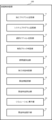
- 4 is a flowchart for explaining processing of the numerical control device of the first disclosure
- FIG. 11 is a block diagram of a numerical controller of the second disclosure
- FIG. 10 is a flow chart for explaining processing of a numerical control device of the second disclosure
- the numerical control device 100 of the first disclosure will be described below.
- the first disclosure describes the numerical control device 100 as an example of an information processing device.
- the information processing device can also be applied to information processing devices other than numerical control devices, such as PCs (personal computers) and servers, as long as they have a function of converting a machining program into a control signal for a machine tool.
- FIG. 1 is a block diagram of the numerical controller 100.
- the numerical controller 100 includes a machining program storage unit 11, a system program storage unit 12, a selection option storage unit 13, an effective block determination unit 14, a machining execution unit 15, a usage amount calculation unit 16, a machining state determination unit 17, and a billing table storage. 18 and a billing fee calculator 19 .
- the machining program storage unit 11 stores the machining programs to be billed.
- FIG. 2 is an example of a machining program.
- a machining program consists of a plurality of lines called blocks.
- the blocks contain codes such as G-codes, M-codes, etc. that specify the functions of the machine tool.
- G-codes G-codes
- M-codes etc. that specify the functions of the machine tool.
- By commanding the code it is possible to set the internal settings of the numerical controller of the machine tool, such as axis movement, coordinate setting, rotation, and target machining method of the tool of the machine tool.
- a system program storage unit 12 stores a system program for converting a machining program into a control signal for a machine tool.
- the system program consists of a basic program and an option program, as shown in FIG. Basic programs are available without charge. Optional programs are charged. Numerical controller 100 is provided with various options. When the user activates an option, the code corresponding to the option and the option program that executes that code are available. Options include, for example, tool center point control, smooth transformer control, and 3D error correction.
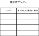
- the selected option storage unit 13 stores valid/invalid codes and options.
- FIG. 4 shows an example of data stored in the selection option storage unit 13. As shown in FIG.
- the valid block determination unit 14 determines whether or not there is a code subject to billing in the processing program. Specifically, the processing program is analyzed, and it is determined whether or not the billable code included in the processing program can be used (the option is valid).
- the machining execution unit 15 analyzes the machining program, generates an axis control signal, and outputs the control signal to the servo system.
- a servomotor of a machine tool drives the motor according to a control signal to perform machining.
- the machining state determination unit 17 determines whether or not processing is being performed using a billable code. There are two methods for determining whether processing is being performed. The first is a method of judging from the operation mode. If the operation mode is dry run, machine lock, or the like, it is determined that the operation is idling and machining is not being performed. The second is a method of confirming the actual movement of the machine. The contact between the tool and the work can be determined based on the spindle load, image recognition, relative positional relationship between the tool and the work, and the like. Based on these data, the billing determination unit determines whether or not processing is actually being performed.
- the usage amount calculation unit 16 calculates the usage amount of the billing target code.
- the code usage includes, but is not limited to, processing execution time, processing execution count, and the like. It should be noted that the usage amount of codes that are not subject to billing may also be calculated. By calculating the usage of various codes, the difference in usage for each code can be seen.
- a condition may be registered in which charging is not performed even if the usage amount is calculated. Examples of conditions under which billing is not charged even if the amount of usage is calculated include malfunction of a machine such as a machine tool or the numerical control device 100, power failure during operation, and the like.
- the usage amount calculation unit 16 does not add the usage amount when processing is interrupted under the registered conditions.
- the usage amount calculator 16 records the usage amount of the code. By recording the amount of usage, it is possible to check the user's usage history, such as the usage time and the number of times the code has been used.
- the billing charge calculator 19 calculates a billing charge based on the usage amount of the code to be billed.
- the billing table storage unit 18 records the unit price of each code.
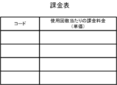
- FIG. 5 shows an example of the billing table.
- the billing table in FIG. 5A consists of codes and billing charges (unit price) per usage time.
- the billing table in FIG. 5B consists of a code and a billing fee (unit price) per use.
- the billing charge calculation unit 19 calculates a billing charge based on the usage amount of the code, such as the execution time of processing the code to be billed, the number of times the processing is executed, and the like.
- the user of numerical controller 100 selects an option to use (step S1).
- the code corresponding to the option selected is valid for use.
- Numerical controller 100 determines a block containing a billable code (step S2).
- the numerical controller 100 starts machining (step S3).
- Numerical controller 100 determines whether machining is being performed (step S4). Judgment is based on operation modes such as dry run and machine lock, spindle load, image recognition, relative positional relationship between the tool and work, and the like. If machining is interrupted under a predesignated condition, it is determined that machining is not being executed.
- the numerical controller 100 calculates the usage amount of the billable code (step S5).
- the amount of code usage includes, but is not limited to, the length of time the code is used, the number of times the code is used, and the like.
- the numerical control device 100 calculates the charge for each code based on the amount of code usage (step S6).
- the numerical control device 100 records the length of time the code was used, the amount of code usage such as the number of times the code was used, and the charge for the code (step S7).
- the numerical control device 100 of the first disclosure searches for a block in which a billable code is described, determines whether or not processing is being executed with the billable code, and determines whether or not the code is used. Calculate the quantity.
- the numerical control device 100 of the first disclosure it is possible to obtain the user's usage records such as option usage time, number of times of usage, and usage fee.
- the usage record it is possible to utilize the usage record to improve the service and lead to the creation of new options.
- the numerical control device 100 of the first disclosure since only the amount of code used is charged, the charge burden on the user is reduced. The user can also confirm how much charge was generated in which block. The user can also select pay-as-you-go billing or flat-rate billing according to the frequency of use.
- the numerical control device 100 of the second disclosure will be described below.
- the second disclosure describes the numerical control device 100 as an example of an information processing device.
- the information processing device can also be applied to information processing devices other than numerical control devices, such as PCs (personal computers) and servers, as long as they have a function of converting a machining program into a control signal for a machine tool.
- FIG. 7 is a block diagram of the numerical controller 100.
- the numerical controller 100 includes a machining program storage unit 11, a system program storage unit 12, a selection option storage unit 13, an effective block determination unit 14, a simulation execution unit 20, a usage amount calculation unit 16, a machining state determination unit 17, and a billing table storage.
- a charging charge calculating unit 19 and a charging charge presenting unit 21 are provided.
- the numerical controller 100 of the second disclosure determines whether or not machining is to be executed by simulation. By simulation, it is possible to calculate information about the usage record of the system program before executing machining.
- the usage history information includes, but is not limited to, the usage time, the number of times of usage, and the charging fee.
- the description of the same components as those of the numerical control device 100 of the first disclosure will be omitted.
- the machining program storage unit 11 stores the machining programs to be billed.
- a system program storage unit 12 stores a system program for converting a machining program into a control signal for a machine tool.
- the system program stores a basic program and an option program, as shown in FIG.
- the basic program is available without charge. Optional programs are charged.
- the selected option storage unit 13 stores a code for which the use of the billable code has been validated by the user's selection of the option.
- the effective block determination unit 14 determines whether or not there is a code subject to billing in the machining program. Specifically, the processing program is analyzed, and it is determined whether or not the billable code included in the processing program can be used (the option is valid).
- the simulation executing section 20 executes a simulation of the machining program. Based on the simulation, the processing state determination unit 17 determines whether or not processing is executed using the billable code. There are two methods for determining whether processing is being performed. The first is a method of judging from the operation mode. If the operation mode is dry run, machine lock, or the like, it is determined that the operation is idling and machining is not being performed. The second is a method of confirming the actual movement of the machine. Contact between the tool and the work can be determined based on the relative positional relationship between the tool and the work. Based on these data, the billing determination unit determines whether or not processing is actually being performed. Calculate the amount of code usage, such as the processing execution time or the number of processing executions.
- the machining state determination unit 17 determines that the operation is idle. Also, it is determined whether or not the workpiece is actually being machined from the coordinate positions of the tool and the workpiece in the simulation.
- the usage amount calculation unit 16 calculates the usage amount of the billing target code.
- the code usage includes, but is not limited to, processing execution time, processing execution count, and the like. It should be noted that the usage of codes that are not subject to billing may also be calculated. By calculating the usage of various codes, the difference in usage for each code can be seen.
- the usage amount calculator 16 records the usage amount of the code. By recording the amount of usage, it is possible to check the usage history of the user, such as the usage time and the number of usages of the code.
- the billing charge calculation unit 19 calculates the billing charge based on the usage amount of the billable code.
- the billing table storage unit 18 stores the unit price of each code.
- the billing charge calculator 19 calculates the billing charge based on the usage amount such as the code usage time and the number of times of use.
- the charging charge presenting unit 21 presents the charging charge calculated by the charging charge calculation unit 19 to the user.
- the user can refer to the billing rate to determine which option to select and which code to use.
- the user of numerical controller 100 selects an option to use (step S11).
- the code corresponding to the option is valid for use.
- Numerical control device 100 determines the existence of a block containing a billable code (step S12).
- Numerical controller 100 starts the simulation (step S13).
- Numerical control device 100 determines whether or not processing is executed using the billable code (step S14). The determination is based on the operation mode, the coordinate positions of the tool and the workpiece in the simulation, and the like.
- the numerical control device 100 calculates the usage amount of the billable code (step S15). As the usage amount of the code, the usage time of the code, the number of times of usage, and the like are obtained.
- the numerical control device 100 calculates the charge for each code based on the amount of code usage (step S16).
- the numerical control device 100 records the length of time the code has been used, the amount of code usage such as the number of times the code has been used, and the charge for the code (step S17).
- the numerical controller 100 notifies the user of the charge for the code based on the simulation (step S18).
- the user confirms the charge based on the simulation and decides whether or not to use the code.
- the numerical control device 100 of the second disclosure searches for a block in which the code to be charged is written, and simulates the machining program. Calculate billable code usage during simulation. With the numerical control device 100 of the second disclosure, it is possible to check the record of option usage, such as code usage time, number of times of usage, and usage fee. In addition, it is possible to utilize the usage record to improve the service and lead to the creation of new options.
- the charge since the charge is calculated during the simulation, the charge can be confirmed before processing is executed. After confirming the charge, the user can take measures such as rewriting the machining program. In addition, the user can confirm how much charge is generated in which block. The user can select pay-as-you-go billing or flat-rate billing according to the frequency of use.
- a CPU 111 included in the numerical controller 100 is a processor that controls the numerical controller 100 as a whole.
- the CPU 111 reads the system program processed in the ROM 112 via the bus and controls the entire numerical controller 100 according to the system program.
- the RAM 113 temporarily stores calculation data, display data, various data input by the user via the input unit 71, and the like.
- the display unit 70 is a monitor attached to the numerical controller 100 or the like.
- the display unit 70 displays an operation screen, a setting screen, and the like of the numerical controller 100 .
- the input unit 71 is integrated with the display unit 70 or is a keyboard, touch panel, or the like that is separate from the display unit 70 .
- the user operates the input unit 71 to perform input to the screen displayed on the display unit 70 .
- the display unit 70 and the input unit 71 may be mobile terminals.
- the non-volatile memory 114 is, for example, a memory that is backed up by a battery (not shown) so that the memory state is retained even when the power of the numerical controller 100 is turned off.
- the non-volatile memory 114 stores machining programs, system programs, available options, billing tables, and the like.
- the nonvolatile memory 114 stores programs read from external devices via an interface (not shown), programs input via the input unit 71, and various data (for example, , setting parameters obtained from the machine tool, etc.) are stored.
- the programs and various data stored in the non-volatile memory 114 may be developed in the RAM 113 at the time of execution/use.
- Various system programs are pre-written in the ROM 112 .
Landscapes
- Engineering & Computer Science (AREA)
- Human Computer Interaction (AREA)
- Manufacturing & Machinery (AREA)
- Physics & Mathematics (AREA)
- General Physics & Mathematics (AREA)
- Automation & Control Theory (AREA)
- Numerical Control (AREA)
Abstract
Description
本開示の一態様である記憶媒体は、1つ又は複数のプロセッサが実行することにより、工作機械の加工プログラムに、課金対象のコードが存在するか否かを判定し、加工プログラムを実行し、加工プログラムを実行する際の工作機械の機械状態を基に、加工が実行されているか否かを判定し、課金対象のコードが実行されている場合、課金対象のコードの使用量を算出する、プロセッサが読み取り可能な命令を記憶する。
以下、第1の開示の数値制御装置100について説明する。
第1の開示は、数値制御装置100を情報処理装置の一例として説明する。情報処理装置は、加工プログラムを工作機械の制御信号に変換する機能があれば数値制御装置以外の情報処理装置、例えば、PC(パーソナルコンピュータ)、サーバなどにも適用できる。
数値制御装置100には、様々なオプションが設けられている。ユーザがオプションを有効にすると、オプションに対応するコード及びそのコードを実行するオプションプログラムが使用可能になる。オプションには、例えば、工具先端点制御、スムーストランス制御、3次元誤差補正などがある。選択オプション記憶部13は、コードとオプションの有効/無効を記憶する。図4は、選択オプション記憶部13に記憶するデータの一例である。
加工が実行されているか否かを判定する方法は2つ挙げられる。1つ目は運転モードから判定する方法である。運転モードがドライラン、マシンロックなどであれば、空運転であり、加工が実行されていないと判定する。
2つ目は、実際の機械の動きを確認する方法である。工具とワークの接触は、主軸負荷、画像認識、工具とワークの相対位置関係などを基に、判定することができる。課金判定部は、これらのデータを基に、実際に加工しているか否かを判定する。
使用量算出部16には、使用量を算出しても課金をしない条件を登録してもよい。使用量を算出しても課金をしない条件としては、例えば、工作機械、数値制御装置100などの機械の不具合、運転中の停電などがある。使用量算出部16は、登録された条件で加工が中断した場合には使用量を加算しない。
使用量算出部16は、コードの使用量を記録する。使用量を記録することによりコードの利用時間、利用回数など、ユーザの利用実績を確認することができる。
課金料金算出部19は、課金対象のコードの加工の実行時間、加工の実行回数などのコードの使用量を基に課金料金を算出する。
数値制御装置100のユーザは、使用するオプションを選択する(ステップS1)。選択されたオプションに対応するコードは、使用が有効となる。
数値制御装置100は、課金対象のコードを含むブロックを判定する(ステップS2)。
数値制御装置100は、加工を開始する(ステップS3)。数値制御装置100は、加工が実行されているか否かを判定する(ステップS4)。判定は、ドライラン、マシンロックなどの運転モード、主軸負荷、画像認識、工具とワークの相対位置関係などに基づく。予め指定された条件で加工を中断した場合には、加工を実行していないと判定する。
以下、第2の開示の数値制御装置100について説明する。
第2の開示は、数値制御装置100を情報処理装置の一例として説明する。情報処理装置は、加工プログラムを工作機械の制御信号に変換する機能があれば数値制御装置以外の情報処理装置、例えば、PC(パーソナルコンピュータ)、サーバなどにも適用できる。
第2の開示の数値制御装置100は、シミュレーションにより加工が実行されるか否かを判定する。シミュレーションにより加工を実行する前にシステムプログラムの使用実績に関する情報を算出することができる。使用実績に関する情報には、使用時間、使用回数、課金料金などがあるが、これに限定されない。
第2の開示の数値制御装置100の説明において、第1の開示の数値制御装置100と同じ構成要素は説明を省略する。
有効ブロック判定部14は、加工プログラムに課金対象となるコードが存在するか否かを判定する。具体的には、加工プログラムを解析し、加工プログラムに含まれる課金対象のコードが使用可能(オプションが有効)か否かを判定する。
加工状態判定部17は、シミュレーションに基づき、課金対象のコードを用いて加工が実行されるか否かを判定する。
加工が実行されているか否かを判定する方法は2つ挙げられる。1つ目は運転モードから判定する方法である。運転モードがドライラン、マシンロックなどであれば、空運転であり、加工が実行されていないと判定する。
2つ目は、実際の機械の動きを確認する方法である。工具とワークの接触は、工具とワークの相対位置関係などを基に、判定することができる。課金判定部は、これらのデータを基に、実際に加工しているか否かを判定する。
加工の実行時間又は加工の実行回数などのコードの使用量を算出する。加工状態判定部17は、シミュレーションの運転モードがドライラン、マシンロックなどであれば空運転であると判定する。また、シミュレーション上の工具とワークの座標位置から実際に加工しているか否かを判定する。
使用量算出部16は、コードの使用量を記録する。使用量を記録することによりコードの利用時間、利用回数など、ユーザの利用実績を確認することができる。
数値制御装置100のユーザは、使用するオプションを選択する(ステップS11)。オプションに対応するコードは、使用が有効となる。
数値制御装置100は、課金対象のコードを含むブロックの存在を判定する(ステップS12)。
数値制御装置100は、シミュレーションを開始する(ステップS13)。数値制御装置100は、課金対象のコードを用いて加工が実行されるか否かを判定する(ステップS14)。判定は、運転モード、及びシミュレーション上の工具とワークの座標位置などに基づく。
図9を参照して、数値制御装置100のハードウェア構成を説明する。数値制御装置100が備えるCPU111は、数値制御装置100を全体的に制御するプロセッサである。CPU111は、バスを介してROM112に加工されたシステムプログラムを読み出し、該システムプログラムに従って数値制御装置100の全体を制御する。RAM113には、一時的な計算データや表示データ、入力部71を介してユーザが入力した各種データ等が一時的に格納される。
11 加工プログラム記憶部
12 システムプログラム記憶部
13 選択オプション記憶部
14 有効ブロック判定部
15 加工実行部
16 使用量算出部
17 加工状態判定部
18 課金表記憶部
19 課金料金算出部
20 シミュレーション実行部
21 課金料金提示部
70 表示部
71 入力部
111 CPU
112 ROM
113 RAM
114 不揮発性メモリ
Claims (9)
- 加工プログラムを工作機械の制御信号に変換するシステムプログラムの使用量を算出する情報処理装置であって、
前記加工プログラムに、課金対象のコードが存在するか否かを判定する有効ブロック判定部と、
前記加工プログラムを実行する際の前記工作機械の機械状態を基に、加工が実行されているか否かを判定する加工状態判定部と、
前記課金対象のコードが実行されている場合、前記課金対象のコードの使用量を算出する使用量算出部と、
を備える情報処理装置。 - 前記使用量算出部は、前記課金対象となるコードが加工を実行する使用時間、使用回数の少なくとも1つを算出する、請求項1記載の情報処理装置。
- 前記加工状態判定部は、前記工作機械が加工を実行しているか否かを判定し、
前記使用量算出部は、前記工作機械における前記課金対象のコードの使用量を算出する、請求項1記載の情報処理装置。 - 前記加工状態判定部は、前記工作機械がシミュレーション上で加工を実行しているか否かを判定し、
前記使用量算出部は、前記シミュレーション上での前記課金対象のコードの使用量を算出する、請求項1記載の情報処理装置。 - 前記加工状態判定部は、前記加工が空運転のとき、前記加工が実行されていないと判定する、請求項1記載の情報処理装置。
- 課金を実行しない条件の登録を受け付け、前記機械状態が前記条件で中断された場合には、課金不要と判定する請求項1記載の情報処理装置。
- 前記課金対象のコードの使用量を基に前記コードの課金料金を算出する課金料金算出部を備える、請求項1記載の情報処理装置。
- 前記シミュレーション上での前記課金対象のコードの使用量を基に、前記コードの課金料金を算出する課金料金算出部と、
前記シミュレーション上での課金料金をユーザに提示する課金料金提示部を備える、請求項4記載の情報処理装置。 - 1つ又は複数のプロセッサが実行することにより、
工作機械の加工プログラムに、課金対象のコードが存在するか否かを判定し、
前記加工プログラムを実行し、
前記加工プログラムを実行する際の前記工作機械の機械状態を基に、加工が実行されているか否かを判定し、
前記課金対象のコードが実行されている場合、前記課金対象のコードの使用量を算出する、
前記プロセッサが読み取り可能な命令を記憶する記憶媒体。
Priority Applications (4)
| Application Number | Priority Date | Filing Date | Title |
|---|---|---|---|
| PCT/JP2021/042923 WO2023095191A1 (ja) | 2021-11-24 | 2021-11-24 | 情報処理装置、及びコンピュータが読み取り可能な記憶媒体 |
| CN202180104319.7A CN118265955A (zh) | 2021-11-24 | 2021-11-24 | 信息处理装置以及计算机可读取的存储介质 |
| JP2023563369A JP7708881B2 (ja) | 2021-11-24 | 2021-11-24 | 情報処理装置、及びコンピュータが読み取り可能な記憶媒体 |
| DE112021008259.0T DE112021008259T5 (de) | 2021-11-24 | 2021-11-24 | Informationsverarbeitungsvorrichtung und computerlesbares Speichermedium |
Applications Claiming Priority (1)
| Application Number | Priority Date | Filing Date | Title |
|---|---|---|---|
| PCT/JP2021/042923 WO2023095191A1 (ja) | 2021-11-24 | 2021-11-24 | 情報処理装置、及びコンピュータが読み取り可能な記憶媒体 |
Publications (1)
| Publication Number | Publication Date |
|---|---|
| WO2023095191A1 true WO2023095191A1 (ja) | 2023-06-01 |
Family
ID=86539077
Family Applications (1)
| Application Number | Title | Priority Date | Filing Date |
|---|---|---|---|
| PCT/JP2021/042923 Ceased WO2023095191A1 (ja) | 2021-11-24 | 2021-11-24 | 情報処理装置、及びコンピュータが読み取り可能な記憶媒体 |
Country Status (4)
| Country | Link |
|---|---|
| JP (1) | JP7708881B2 (ja) |
| CN (1) | CN118265955A (ja) |
| DE (1) | DE112021008259T5 (ja) |
| WO (1) | WO2023095191A1 (ja) |
Citations (2)
| Publication number | Priority date | Publication date | Assignee | Title |
|---|---|---|---|---|
| JP2020009166A (ja) * | 2018-07-09 | 2020-01-16 | 三菱日立パワーシステムズ株式会社 | プラント運転方法、制御装置及びプログラム |
| JP2020017029A (ja) * | 2018-07-24 | 2020-01-30 | 株式会社ダイヘン | オプション機能使用料演算方法、オプション機能使用料演算装置及びコンピュータプログラム |
Family Cites Families (1)
| Publication number | Priority date | Publication date | Assignee | Title |
|---|---|---|---|---|
| JP2016081469A (ja) | 2014-10-22 | 2016-05-16 | ファナック株式会社 | 数値制御装置のオプション機能の使用状況管理システム |
-
2021
- 2021-11-24 WO PCT/JP2021/042923 patent/WO2023095191A1/ja not_active Ceased
- 2021-11-24 JP JP2023563369A patent/JP7708881B2/ja active Active
- 2021-11-24 DE DE112021008259.0T patent/DE112021008259T5/de active Pending
- 2021-11-24 CN CN202180104319.7A patent/CN118265955A/zh active Pending
Patent Citations (2)
| Publication number | Priority date | Publication date | Assignee | Title |
|---|---|---|---|---|
| JP2020009166A (ja) * | 2018-07-09 | 2020-01-16 | 三菱日立パワーシステムズ株式会社 | プラント運転方法、制御装置及びプログラム |
| JP2020017029A (ja) * | 2018-07-24 | 2020-01-30 | 株式会社ダイヘン | オプション機能使用料演算方法、オプション機能使用料演算装置及びコンピュータプログラム |
Also Published As
| Publication number | Publication date |
|---|---|
| DE112021008259T5 (de) | 2024-07-18 |
| JPWO2023095191A1 (ja) | 2023-06-01 |
| JP7708881B2 (ja) | 2025-07-15 |
| CN118265955A (zh) | 2024-06-28 |
Similar Documents
| Publication | Publication Date | Title |
|---|---|---|
| CN103076762B (zh) | 基于htm40100车铣复合加工中心三维在线防碰撞方法 | |
| EP3831544A1 (en) | Method, device and system for correcting offline programming program, medium, and terminal | |
| CN101303585B (zh) | 控制装置 | |
| CN102163047A (zh) | 学习控制机器人 | |
| CN109605367B (zh) | 一种机器人编程方法、装置及设备、存储介质 | |
| JP2013136123A (ja) | ロボット動作教示支援装置及び方法 | |
| JPWO2004083975A1 (ja) | 数値制御システム | |
| CN109143979B (zh) | 数控设备的加工控制方法、系统、可读存储介质和设备 | |
| WO2023095191A1 (ja) | 情報処理装置、及びコンピュータが読み取り可能な記憶媒体 | |
| JP2016164721A (ja) | 加工工程管理機能付き数値制御装置および加工工程管理プログラム | |
| JPH1189291A (ja) | モータの加減速制御方法 | |
| CN114489616A (zh) | 一种工控上位机运动控制系统及软件编辑方法 | |
| US20040210338A1 (en) | Numerical control apparatus | |
| CN116300693B (zh) | 数控伺服系统的同步方法及应用 | |
| JPS61147307A (ja) | 干渉回避機能を備えたロボツト制御装置 | |
| US20080263541A1 (en) | Computer-readable recording medium for recovery of software | |
| CN113848867B (zh) | 一种车辆冗余控制方法、装置、设备及存储介质 | |
| JP2019169136A (ja) | セーフティクリティカルなシステムでデータを計算するための方法及び装置 | |
| CN120779859B (zh) | 数控加工方法、电子设备、存储介质及计算机程序产品 | |
| US6085264A (en) | Accounting-information outputting device | |
| JPS58222357A (ja) | 駆動制御プログラムデバツグ方式 | |
| TWI899926B (zh) | 動作程式產生裝置及動作程式產生方法 | |
| CN116100578B (zh) | 一种双关节机器人的指令快速响应系统 | |
| JP7772829B2 (ja) | プログラム教示支援装置 | |
| CN116534123B (zh) | 挂车横向控制方法、装置以及目标挂车 |
Legal Events
| Date | Code | Title | Description |
|---|---|---|---|
| 121 | Ep: the epo has been informed by wipo that ep was designated in this application |
Ref document number: 21965565 Country of ref document: EP Kind code of ref document: A1 |
|
| WWE | Wipo information: entry into national phase |
Ref document number: 2023563369 Country of ref document: JP |
|
| WWE | Wipo information: entry into national phase |
Ref document number: 18710490 Country of ref document: US |
|
| WWE | Wipo information: entry into national phase |
Ref document number: 202180104319.7 Country of ref document: CN Ref document number: 112021008259 Country of ref document: DE |
|
| 122 | Ep: pct application non-entry in european phase |
Ref document number: 21965565 Country of ref document: EP Kind code of ref document: A1 |