WO2023090415A1 - 測距装置 - Google Patents
測距装置 Download PDFInfo
- Publication number
- WO2023090415A1 WO2023090415A1 PCT/JP2022/042828 JP2022042828W WO2023090415A1 WO 2023090415 A1 WO2023090415 A1 WO 2023090415A1 JP 2022042828 W JP2022042828 W JP 2022042828W WO 2023090415 A1 WO2023090415 A1 WO 2023090415A1
- Authority
- WO
- WIPO (PCT)
- Prior art keywords
- light
- detection process
- control unit
- reflected light
- measuring device
- Prior art date
- Legal status (The legal status is an assumption and is not a legal conclusion. Google has not performed a legal analysis and makes no representation as to the accuracy of the status listed.)
- Ceased
Links
Images



Classifications
-
- G—PHYSICS
- G01—MEASURING; TESTING
- G01S—RADIO DIRECTION-FINDING; RADIO NAVIGATION; DETERMINING DISTANCE OR VELOCITY BY USE OF RADIO WAVES; LOCATING OR PRESENCE-DETECTING BY USE OF THE REFLECTION OR RERADIATION OF RADIO WAVES; ANALOGOUS ARRANGEMENTS USING OTHER WAVES
- G01S7/00—Details of systems according to groups G01S13/00, G01S15/00, G01S17/00
- G01S7/48—Details of systems according to groups G01S13/00, G01S15/00, G01S17/00 of systems according to group G01S17/00
- G01S7/497—Means for monitoring or calibrating
-
- G—PHYSICS
- G01—MEASURING; TESTING
- G01S—RADIO DIRECTION-FINDING; RADIO NAVIGATION; DETERMINING DISTANCE OR VELOCITY BY USE OF RADIO WAVES; LOCATING OR PRESENCE-DETECTING BY USE OF THE REFLECTION OR RERADIATION OF RADIO WAVES; ANALOGOUS ARRANGEMENTS USING OTHER WAVES
- G01S7/00—Details of systems according to groups G01S13/00, G01S15/00, G01S17/00
- G01S7/48—Details of systems according to groups G01S13/00, G01S15/00, G01S17/00 of systems according to group G01S17/00
- G01S7/483—Details of pulse systems
- G01S7/486—Receivers
- G01S7/4868—Controlling received signal intensity or exposure of sensor
-
- G—PHYSICS
- G01—MEASURING; TESTING
- G01S—RADIO DIRECTION-FINDING; RADIO NAVIGATION; DETERMINING DISTANCE OR VELOCITY BY USE OF RADIO WAVES; LOCATING OR PRESENCE-DETECTING BY USE OF THE REFLECTION OR RERADIATION OF RADIO WAVES; ANALOGOUS ARRANGEMENTS USING OTHER WAVES
- G01S17/00—Systems using the reflection or reradiation of electromagnetic waves other than radio waves, e.g. lidar systems
- G01S17/02—Systems using the reflection of electromagnetic waves other than radio waves
- G01S17/06—Systems determining position data of a target
- G01S17/08—Systems determining position data of a target for measuring distance only
- G01S17/10—Systems determining position data of a target for measuring distance only using transmission of interrupted, pulse-modulated waves
-
- G—PHYSICS
- G01—MEASURING; TESTING
- G01S—RADIO DIRECTION-FINDING; RADIO NAVIGATION; DETERMINING DISTANCE OR VELOCITY BY USE OF RADIO WAVES; LOCATING OR PRESENCE-DETECTING BY USE OF THE REFLECTION OR RERADIATION OF RADIO WAVES; ANALOGOUS ARRANGEMENTS USING OTHER WAVES
- G01S17/00—Systems using the reflection or reradiation of electromagnetic waves other than radio waves, e.g. lidar systems
- G01S17/02—Systems using the reflection of electromagnetic waves other than radio waves
- G01S17/06—Systems determining position data of a target
- G01S17/42—Simultaneous measurement of distance and other co-ordinates
-
- G—PHYSICS
- G01—MEASURING; TESTING
- G01S—RADIO DIRECTION-FINDING; RADIO NAVIGATION; DETERMINING DISTANCE OR VELOCITY BY USE OF RADIO WAVES; LOCATING OR PRESENCE-DETECTING BY USE OF THE REFLECTION OR RERADIATION OF RADIO WAVES; ANALOGOUS ARRANGEMENTS USING OTHER WAVES
- G01S7/00—Details of systems according to groups G01S13/00, G01S15/00, G01S17/00
- G01S7/48—Details of systems according to groups G01S13/00, G01S15/00, G01S17/00 of systems according to group G01S17/00
- G01S7/4802—Details of systems according to groups G01S13/00, G01S15/00, G01S17/00 of systems according to group G01S17/00 using analysis of echo signal for target characterisation; Target signature; Target cross-section
-
- G—PHYSICS
- G01—MEASURING; TESTING
- G01S—RADIO DIRECTION-FINDING; RADIO NAVIGATION; DETERMINING DISTANCE OR VELOCITY BY USE OF RADIO WAVES; LOCATING OR PRESENCE-DETECTING BY USE OF THE REFLECTION OR RERADIATION OF RADIO WAVES; ANALOGOUS ARRANGEMENTS USING OTHER WAVES
- G01S7/00—Details of systems according to groups G01S13/00, G01S15/00, G01S17/00
- G01S7/48—Details of systems according to groups G01S13/00, G01S15/00, G01S17/00 of systems according to group G01S17/00
- G01S7/481—Constructional features, e.g. arrangements of optical elements
- G01S7/4814—Constructional features, e.g. arrangements of optical elements of transmitters alone
-
- G—PHYSICS
- G01—MEASURING; TESTING
- G01S—RADIO DIRECTION-FINDING; RADIO NAVIGATION; DETERMINING DISTANCE OR VELOCITY BY USE OF RADIO WAVES; LOCATING OR PRESENCE-DETECTING BY USE OF THE REFLECTION OR RERADIATION OF RADIO WAVES; ANALOGOUS ARRANGEMENTS USING OTHER WAVES
- G01S7/00—Details of systems according to groups G01S13/00, G01S15/00, G01S17/00
- G01S7/48—Details of systems according to groups G01S13/00, G01S15/00, G01S17/00 of systems according to group G01S17/00
- G01S7/481—Constructional features, e.g. arrangements of optical elements
- G01S7/4816—Constructional features, e.g. arrangements of optical elements of receivers alone
-
- G—PHYSICS
- G01—MEASURING; TESTING
- G01S—RADIO DIRECTION-FINDING; RADIO NAVIGATION; DETERMINING DISTANCE OR VELOCITY BY USE OF RADIO WAVES; LOCATING OR PRESENCE-DETECTING BY USE OF THE REFLECTION OR RERADIATION OF RADIO WAVES; ANALOGOUS ARRANGEMENTS USING OTHER WAVES
- G01S7/00—Details of systems according to groups G01S13/00, G01S15/00, G01S17/00
- G01S7/48—Details of systems according to groups G01S13/00, G01S15/00, G01S17/00 of systems according to group G01S17/00
- G01S7/481—Constructional features, e.g. arrangements of optical elements
- G01S7/4817—Constructional features, e.g. arrangements of optical elements relating to scanning
-
- G—PHYSICS
- G01—MEASURING; TESTING
- G01S—RADIO DIRECTION-FINDING; RADIO NAVIGATION; DETERMINING DISTANCE OR VELOCITY BY USE OF RADIO WAVES; LOCATING OR PRESENCE-DETECTING BY USE OF THE REFLECTION OR RERADIATION OF RADIO WAVES; ANALOGOUS ARRANGEMENTS USING OTHER WAVES
- G01S17/00—Systems using the reflection or reradiation of electromagnetic waves other than radio waves, e.g. lidar systems
- G01S17/88—Lidar systems specially adapted for specific applications
- G01S17/93—Lidar systems specially adapted for specific applications for anti-collision purposes
- G01S17/931—Lidar systems specially adapted for specific applications for anti-collision purposes of land vehicles
-
- G—PHYSICS
- G01—MEASURING; TESTING
- G01S—RADIO DIRECTION-FINDING; RADIO NAVIGATION; DETERMINING DISTANCE OR VELOCITY BY USE OF RADIO WAVES; LOCATING OR PRESENCE-DETECTING BY USE OF THE REFLECTION OR RERADIATION OF RADIO WAVES; ANALOGOUS ARRANGEMENTS USING OTHER WAVES
- G01S7/00—Details of systems according to groups G01S13/00, G01S15/00, G01S17/00
- G01S7/48—Details of systems according to groups G01S13/00, G01S15/00, G01S17/00 of systems according to group G01S17/00
- G01S7/497—Means for monitoring or calibrating
- G01S2007/4975—Means for monitoring or calibrating of sensor obstruction by, e.g. dirt- or ice-coating, e.g. by reflection measurement on front-screen
-
- G—PHYSICS
- G01—MEASURING; TESTING
- G01S—RADIO DIRECTION-FINDING; RADIO NAVIGATION; DETERMINING DISTANCE OR VELOCITY BY USE OF RADIO WAVES; LOCATING OR PRESENCE-DETECTING BY USE OF THE REFLECTION OR RERADIATION OF RADIO WAVES; ANALOGOUS ARRANGEMENTS USING OTHER WAVES
- G01S7/00—Details of systems according to groups G01S13/00, G01S15/00, G01S17/00
- G01S7/48—Details of systems according to groups G01S13/00, G01S15/00, G01S17/00 of systems according to group G01S17/00
- G01S7/483—Details of pulse systems
- G01S7/486—Receivers
- G01S7/487—Extracting wanted echo signals, e.g. pulse detection
- G01S7/4876—Extracting wanted echo signals, e.g. pulse detection by removing unwanted signals
Definitions
- the present invention relates to a rangefinder.
- a rangefinder is one that measures the time it takes for emitted light to be reflected by an object and return to measure the distance to surrounding objects.
- Patent Literature 1 describes monitoring the light reception power and operating the window cleaning device when it is necessary to remove dirt from the window.
- the dirt cannot be removed immediately.
- the light reflected by the window saturates the light receiving section, and the received light signal may be affected by the saturation for a relatively long time. Then, the reflected light from the object to be measured may not be detected during the period when the influence of saturation remains.
- One example of the problem to be solved by the present invention is to improve the possibility of distance measurement under the influence of adhering matter.
- a distance measuring device that emits light through a transparent member and detects reflected light from an object, a light receiving unit that receives internally reflected light including reflected light reflected by the transmissive member and reflected light from the object; and a switching control unit that switches detection processing of the reflected light from the object using the result of light reception of the internal reflected light by the light receiving unit.
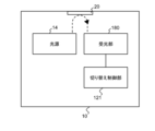
- FIG. 1 is a diagram illustrating the configuration of a distance measuring device according to a first embodiment
- FIG. 1 is a diagram illustrating a distance measuring device according to a first embodiment
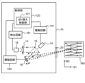
- FIG. 1 is a diagram illustrating in detail the configuration of a distance measuring device according to a first embodiment
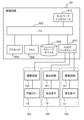
- FIG. 4 is a diagram illustrating the hardware configuration of a control unit according to the first embodiment
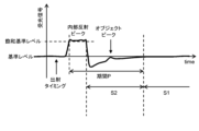
- FIG. FIG. 4 is a diagram illustrating waveforms of light receiving signals of a light receiving unit
- 6 is a flow chart showing a flow of a first example of switching processing performed by a switching control unit according to the first embodiment
- FIG. 10 is a diagram showing another example of the waveform of the light receiving signal of the light receiving section; 9 is a flow chart showing a flow of a second example of switching processing performed by the switching control unit according to the first embodiment;
- FIG. 4 is a diagram illustrating a map showing the distribution of received light intensity of internally reflected light in a frame and a map showing the distribution of saturation time;
- 9 is a flowchart illustrating the flow of processing performed by a switching control unit according to the second embodiment;
- FIG. 1 is a diagram illustrating the configuration of a distance measuring device 10 according to the first embodiment.
- FIG. 2 is a diagram illustrating the distance measuring device 10 according to this embodiment.
- dashed arrows schematically indicate paths of light.
- a distance measuring device 10 according to this embodiment is a device that emits light through a transmission member 20 and detects reflected light from an object 30 .
- the distance measuring device 10 includes a light receiving section 180 and a switching control section 121 .
- the light receiving unit 180 receives internally reflected light including reflected light reflected by the transmissive member 20 and reflected light from the object 30 .
- the switching control unit 121 switches detection processing of the reflected light from the target object 30 using the light receiving result of the internally reflected light by the light receiving unit 180 .
- a detailed description is given below.
- the light emitted from the light source 14 is emitted to the outside of the distance measuring device 10 mainly through the transmission member 20 as shown in FIG.
- at least part of the light output from the light source 14 is reflected inside the distance measuring device 10 as shown in FIG. 1 and becomes internally reflected light.
- the internally reflected light is received by the light receiving section 180 .
- This internally reflected light includes the light reflected by the transmissive member 20 .
- the reflected light due to the deposit is included in the internally reflected light.
- the transmission member 20 is a member that separates the inside and outside of the distance measuring device 10 and that transmits light.
- Transmissive member 20 is made of, for example, glass or resin. At least one surface of the transmissive member 20 is exposed to the space outside the range finder 10, and dirt, raindrops, and the like may adhere to it.
- the reflected light caused by the deposit includes, for example, light reflected at the interface between the transmissive member 20 and the deposit, light reflected inside the deposit, and light reflected at the interface between the deposit and air. include.
- the light receiving section 180 receives internally reflected light and reflected light from the object 30 .
- the switching control unit 121 switches detection processing of the reflected light from the target object 30 using the light receiving result of the internally reflected light by the light receiving unit 180 .
- the light receiving result of the internally reflected light includes the light receiving result of the period when the influence of the light receiving of the internally reflected light occurs.
- the detection processing will be described later in detail. It is assumed that the object 30 is not attached to the transmissive member 20 , that is, is not in contact with the transmissive member 20 .
- FIG. 3 is a diagram illustrating in detail the configuration of the distance measuring device 10 according to this embodiment.
- dashed arrows schematically indicate paths of light.
- the configuration of the distance measuring device 10 will be described in detail with reference to this figure.
- Distance measuring device 10 measures the distance between distance measuring device 10 and an object (target object 30) within scanning range 160 based on, for example, the difference between the emission timing of pulsed light and the reception timing of reflected light (reflected pulsed light). It is a device for measuring distance.
- the pulsed light is light such as infrared light, for example.
- the pulsed light is, for example, a laser pulse.
- the pulsed light emitted from the light source 14 provided in the distance measuring device 10 and emitted to the outside of the distance measuring device 10 through the transmission member 20 is reflected by an object and at least part of it is directed toward the distance measuring device 10. return. Then, the reflected light passes through the transmission member 20 again and enters the distance measuring device 10 .
- the reflected light incident on the distance measuring device 10 is received by the light receiving section 180 and its intensity is detected.
- the distance measuring device 10 measures the time from when the pulsed light is emitted from the light source 14 to when the reflected light is detected by the light receiving section 180 .
- the control unit 120 provided in the distance measuring device 10 calculates the distance between the distance measuring device 10 and the object using the measured time and the propagation speed of the pulsed light.
- the ranging device 10 is, for example, a lidar (LIDAR: Laser Imaging Detection and Ranging, Laser Illuminated Detection and Ranging or LiDAR: Light Detection and Ranging) device.
- the light source 14 emits pulsed light.
- Light source 14 is, for example, a laser diode.
- Light receiving section 180 includes light receiving element 18 and detection circuit 181 .
- the light receiving element 18 receives the pulsed light incident on the distance measuring device 10 and the internal reflected light described above.
- Light receiving element 18 is, for example, a photodiode such as an avalanche photodiode (APD).
- APD avalanche photodiode
- the distance measuring device 10 further includes a movable mirror 16.
- the movable mirror 16 is, for example, a uniaxially movable or biaxially movable MEMS mirror. By changing the orientation of the reflecting surface of the movable mirror 16, the emission direction of the pulsed light emitted from the distance measuring device 10 can be changed.
- the movable mirror 16 is a biaxially movable MEMS mirror, by biaxially driving the movable mirror 16, raster scanning can be performed within a predetermined range with pulsed light.
- the control unit 120 generates point cloud data including measurement results using a plurality of pulsed lights. For example, when raster scanning is performed within the scanning range 160 , linear scanning is performed by changing the light emission direction to the first direction 161 . By performing a plurality of linear scans while changing the light emitting direction in the second direction 162, point cloud data including a plurality of measurement results within the scanning range 160 can be generated.
- the first direction 161 and the second direction 162 are orthogonal.
- a unit of point cloud data generated by a single raster scan is called a frame. After the measurement of one frame is finished, the direction of light emission returns to the initial position, and the measurement of the next frame is performed. Thus, repeating frames are generated.
- distances measured by pulsed light are associated with information indicating the emission direction of the pulsed light.
- the point cloud data may include three-dimensional coordinates indicating reflection points of the pulsed light.
- the control unit 120 generates point cloud data using the calculated distance and information indicating the angle of the movable mirror 16 when emitting each pulsed light.
- the generated point cloud data may be output to the outside of the distance measuring device 10 or may be held in a storage device accessible from the control unit 120 .
- the distance measuring device 10 further includes a mirror 15 with a hole and a condenser lens 13 .
- the pulsed light emitted from the light source 14 passes through the hole of the mirror 15 with a hole, is reflected by the movable mirror 16 , and is emitted from the distance measuring device 10 .
- the reflected light incident on the distance measuring device 10 is reflected by the movable mirror 16 and the holed mirror 15 , and then enters the light receiving section 180 via the condenser lens 13 .
- the distance measuring device 10 may further include a collimating lens, a mirror, and the like.
- the control section 120 can control the light emitting section 140, the light receiving section 180, and the movable reflecting section 164 (see FIG. 4).
- Light emitting section 140 , light receiving section 180 and movable reflecting section 164 are included in distance measuring device 10 .
- Light emitting unit 140 includes light source 14 and drive circuit 141 .
- Light receiving section 180 includes light receiving element 18 and detection circuit 181 .
- Movable reflector 164 includes movable mirror 16 and drive circuit 163 .
- the drive circuit 141 is a circuit for causing the light source 14 to emit light based on the control signal from the integrated circuit 80, and includes, for example, a switching circuit and a capacitive element.
- the detection circuit 181 includes an IV converter and an amplifier, and outputs a signal indicating the intensity of light detected by the light receiving element 18 .
- the control unit 120 acquires a light receiving signal from the light receiving unit 180 and performs detection processing, which will be described later, on the light receiving signal, thereby detecting a peak due to reflected light from the object 30 . Then, the distance from the distance measuring device 10 to the object 30 within the scanning range 160 is calculated as described above using the detected peak light receiving timing and light emitting timing. Further, the control unit 120 includes a switching control unit 121, and the switching control unit 121 performs switching of detection processing for distance measurement.
- FIG. 4 is a diagram illustrating the hardware configuration of the control unit 120 according to this embodiment.
- the controller 120 is implemented using an integrated circuit 80 .
- the integrated circuit 80 is, for example, an SoC (System On Chip).
- the integrated circuit 80 has a bus 802 , a processor 804 , a memory 806 , a storage device 808 , an input/output interface 810 and a network interface 812 .
- a bus 802 is a data transmission path for the processor 804, memory 806, storage device 808, input/output interface 810, and network interface 812 to transmit and receive data to and from each other.
- the processor 804 is an arithmetic processing device implemented using a microprocessor or the like.
- a memory 806 is a memory implemented using a RAM (Random Access Memory) or the like.
- the storage device 808 is a storage device implemented using ROM (Read Only Memory), flash memory, or the like.
- the input/output interface 810 is an interface for connecting the integrated circuit 80 with peripheral devices.
- an input/output interface 810 is connected to a drive circuit 141 for the light source 14, a detection circuit 181 for the light receiving element 18, and a drive circuit 163 for the movable mirror 16.
- a network interface 812 is an interface for connecting the integrated circuit 80 to a communication network.
- This communication network is, for example, a CAN (Controller Area Network), Ethernet, LVDS (Low Voltage Differential Signaling), or the like.
- a method for connecting the network interface 812 to the communication network may be a wireless connection or a wired connection.
- the storage device 808 stores program modules for realizing the functions of the control unit 120 including the switching control unit 121.
- the processor 804 implements the functions of the control unit 120 including the switching control unit 121 by reading this program module into the memory 806 and executing it.
- the hardware configuration of the integrated circuit 80 is not limited to the configuration shown in this figure.
- program modules may be stored in memory 806 .
- integrated circuit 80 may not include storage device 808 .
- FIG. 5 is a diagram illustrating the waveform of the light receiving signal of the light receiving section 180.
- FIG. The internally reflected light described above is received by the light receiving section 180 immediately after the light is emitted from the light source 14 .
- the reflected light from the object 30 is received by the light receiving section 180 at a timing corresponding to the distance from the distance measuring device 10 to the object 30 .
- the received light signal output from the light receiving unit 180 includes a peak due to the reception of internal reflected light (hereinafter also referred to as an “internal reflection peak”) and a peak from the object 30 .
- Peaks due to the reception of reflected light appear apart from each other. That is, in this case, it can be said that the first peak in the received light signal after the light is emitted is the internal reflection peak, and the second and subsequent peaks are the object peaks. However, the closer the object 30 is to the rangefinder 10, the closer these peaks are to each other.
- the peak intensity of the received internally reflected light may exceed the detection range of the light receiving section 180, and the light receiving signal of the light receiving section 180 may be saturated as shown in FIG. Once the light receiving section 180 is saturated, it takes time to return to the original signal level (reference level) due to charge accumulation in the light receiving element 18 or the like. If the reflected light from the object 30 enters the light receiving section 180 before the signal level returns to the original level, it becomes necessary to detect the object peak under the influence of the received internal reflected light.
- the received light signal is a signal output from the detection circuit 181 and input to the control unit 120 .
- the reference level is, for example, the received light signal level when no light is incident on the light receiving element 18 , and is the received light signal level when no pulsed light is incident on the light receiving element 18 .
- the received light signal is a signal that reflects the circuit characteristics of the light receiving element 18 and the detection circuit 181, and a negative received light signal may be output as shown in this figure due to the circuit characteristics.
- the polarity of the received light signal with respect to the received light intensity is not limited to the example shown in this figure.
- the light receiving section 180 may have a configuration in which a larger light receiving signal is output in the negative direction as the intensity of light received by the light receiving element 18 increases. Also in the following description, polarities in processing and the like are appropriately set.
- the received light signal rises and saturates.
- the level returns to zero level (reference level), and the detection circuit 181 outputs a signal value of negative polarity. After the light reception signal takes a minimum value, it gradually returns to the reference level. An object peak exists between taking this local minimum and returning to the reference level.
- a detection process for detecting a peak from a received light signal will be described below.
- the switching control unit 121 switches between the first detection process and the second detection process as the detection process.
- the first detection process is a detection process based on the level of the received light signal output from the light receiving unit 180 relative to the reference level. Specifically, in the first detection process, first, a value L is calculated by subtracting the reference level from the received light signal level. Then, a period in which the value L exceeds a predetermined threshold value is specified, and the point at which the value L is maximum during that period is detected as the peak position. However, this point and several points around this point may be used to perform further processing for increasing the distance accuracy to identify the peak position.
- the predetermined threshold is set to a value greater than the noise level. In the first detection process, peaks whose peak intensities are below the reference level are not detected.
- the second detection processing is detection processing based on the slope of the level of the received light signal output from the light receiving unit 180 . Specifically, in the second detection process, the differential value at each point (time point) of the received light signal is calculated, and the point at which the polarity of the calculated differential value switches from positive to negative is detected as the peak position. However, this point and several points around this point may be used to perform further processing for increasing the distance accuracy to identify the peak position.
- the first detection process can detect peaks with higher accuracy than the second detection process, so it is preferable to use the first detection process with priority as much as possible.
- the peak intensity of the object peak is below the reference level and is not detected by the first detection process.
- such object peaks can be detected by the second detection process.
- switching is performed so as to perform the second detection process in a situation where detection by the first detection process is difficult. Therefore, it is possible to improve the possibility of distance measurement under the influence of adhering matter while maintaining high detection accuracy.
- the switching control unit 121 performs the second detection process until the light receiving signal steadily returns to the reference level after receiving the internally reflected light, and otherwise performs the first detection process. So switch. By doing so, object peaks can be detected even under the influence of saturation of internal reflection peaks.
- ⁇ Saturation period> The period during which the saturation of the internal reflection peak affects is hereinafter referred to as the saturation period.
- the waveform of the internal reflection peak differs depending on the type of adhering matter, for example, if the adhering matter is moisture, the waveform is affected by saturation for a long period of time.
- period P indicates a saturation period.
- the start of the saturation period is the start of saturation at the internal reflection peak.
- a state in which the light receiving signal output from the light receiving section 180 exceeds a predetermined saturation reference level is assumed to be a state in which the light receiving section 180 is saturated.
- the switching control unit 121 identifies the point at which the light reception signal becomes equal to or higher than the predetermined saturation reference level for the first time after the light is emitted as the start point of the saturation period.
- the saturation reference level is, for example, slightly smaller than the saturation level of light receiving section 180 .
- the saturation level means the maximum received light intensity that can be detected without saturating the light receiving section 180 .
- the end point of the saturation period is the point at which the received light signal steadily returns to the reference level.
- the end point of the saturation period can be the earlier of the second zero-crossing point after saturation and the first convergence point after saturation.
- the switching control unit 121 determines that a convergence state is reached when a state in which the signal value is within a predetermined convergence level range continues for a predetermined length. Then, when it is determined that a converging state has occurred, the point at which that state begins, that is, the point at which the signal value changes from outside the convergence level range to within the convergence level range is changed to the point at which convergence occurs for the first time after saturation.
- the convergence level range is a range including zero in between, the upper limit of the convergence level range is slightly greater than zero, and the lower limit of the convergence level range is slightly less than zero.
- the difference between the upper convergence level range and zero can be greater than the difference between the lower convergence level range and zero. This is because, for example, when disturbance light is incident on the distance measuring device 10, the received light signal may converge to a level greater than zero due to the disturbance light.
- the switching control unit 121 selects the earlier of the second zero-crossing point after saturation and the first convergence point after saturation, and specifies it as the end point of the saturated engine. It is not necessary that either the second zero-crossing point after saturation or the first convergence point after saturation does not exist. In this case, the switching control unit 121 sets the end point of the saturation period to the end point of the saturation period, whichever can be specified between the second zero-crossing point after saturation and the first convergence point after saturation.
- the end point of the saturation period is the first point in time when the received light signal is within the convergence level range and the slope of the received light signal is within a predetermined range including zero after the end of the saturation state, or such a state It is also possible to set the point of time when is continued for a predetermined number of points.
- FIG. 6 is a flowchart showing the flow of a first example of switching processing performed by the switching control unit 121 according to this embodiment.
- the switching control unit 121 monitors the received light signal and determines whether or not the intensity of the first received light pulse is equal to or higher than the saturation reference level (S11). If the intensity of the first light-receiving pulse is not equal to or higher than the saturation reference level (No in S11), the switching control unit 121 sets the first detection process as the detection process to be performed after the first light-receiving pulse (S15). After that, the first detection process is set as the detection process to be performed for all the detection values until the next pulsed light emission.
- the switching control unit 121 determines whether the saturation state of the light-receiving signal has been resolved (S12). If the saturation state has not been resolved (No in S12), the switching control unit 121 continues monitoring the detection value from the light receiving unit 180 and repeats this determination until the saturation state is resolved (S12). When the saturation state is resolved (Yes in S12), the switching control unit 121 determines whether the detected value (light receiving signal point) after the saturation state is resolved is within the range of the period P by the method described above ( S13).
- the switching control unit 121 sets the second detection process as the detection process to be performed on the detected value (S14). Next, the switching control unit 121 determines whether or not the next detected value is within the period P (S13). In this manner, the determination of S13 and the setting of the second detection process are repeated for each detection value until the range of the period P is passed. When the detected value is no longer within the range of the period P (No in S13), the switching control unit 121 sets the first detection process as the detection process to be performed on the detected value (S15). After that, the first detection process is set as the detection process to be performed for all the detection values until the next pulsed light emission.
- the first detection process or the second detection process is set for all detection values for which peak detection should be performed.
- the detection process to be performed is set by the switching control unit 121
- the set detection process is executed by the control unit 120 .
- peak detection that is, identification of whether or not a certain detection value is a peak
- the setting of the detection process by the switching control unit 121 may be delayed.
- the setting contents of the detection process for each detection value by the switching control unit 121 may be held at least temporarily in a storage unit (for example, the storage device 808).
- the determination of detection processing by the switching control unit 121 and the peak detection by the control unit 120 may be performed collectively for each light emission, or may be collectively performed for each frame.
- detection processing is set as shown in FIG. In FIG. 5, "S2" indicates the period during which peak detection is performed by the second detection process, and “S1" indicates the period during which peak detection is performed by the first detection process.
- FIG. 7 is a diagram showing another example of the waveform of the light receiving signal of the light receiving section 180.
- the object peak is located within the saturation period. This is because it cannot be said that the received light signal has converged to the reference level at the position of the object peak.
- the peak intensity of the object peak exceeds the reference level, and the object peak can be detected by the first detection process.
- FIG. 8 is a flowchart showing the flow of a second example of switching processing performed by the switching control unit 121 according to this embodiment.
- the switching control unit 121 monitors the received light signal and determines whether or not the intensity of the first received light pulse is equal to or higher than the saturation reference level (S11). If the intensity of the first light-receiving pulse is not equal to or higher than the saturation reference level (No in S11), the switching control unit 121 sets the first detection process as the detection process to be performed after the first light-receiving pulse (S15). After that, the first detection process is set as the detection process to be performed for all the detection values until the next pulsed light emission.
- the switching control unit 121 determines whether the received light signal is below the reference level (S121). If the received light signal does not fall below the reference level (No in S121), the switching control unit 121 continues monitoring the detected value from the light receiving unit 180 and repeats this determination until it falls below (S121). When the received light signal falls below the reference level (Yes in S121), the switching control unit 121 determines whether or not the detected value after falling below the reference level is within the range of the period P by the method described above (S13). ).
- the switching control unit 121 determines whether the detected value is equal to or higher than the reference level (S132). If the detected value is not equal to or higher than the reference level (No in S132), the switching control unit 121 sets the second detection process as the detection process to be performed on the detected value (S14). Next, the switching control unit 121 determines whether or not the next detected value is within the period P (S13). If the detected value is equal to or higher than the reference level in S132 (Yes in S132), the switching control unit 121 sets the first detection process as the detection process to be performed on the detected value (S152).
- the switching control unit 121 returns to S13 for the next detected value and determines whether it is within the range of the period P or not. If the detected value is not within the range of the period P in S13 (No in S13), the switching control unit 121 sets the first detection process as the detection process to be performed on the detected value (S15). After that, the first detection process is set as the detection process to be performed for all the detection values until the next pulsed light emission.
- the first detection process or the second detection process is set for all detection values for which peak detection should be performed.
- the detection process to be performed is set by the switching control unit 121
- the set detection process is executed by the control unit 120 .
- peak detection that is, identification of whether or not a certain detection value is a peak
- the setting of the detection process by the switching control unit 121 may be delayed.
- the setting contents of the detection process for each detection value by the switching control unit 121 may be held at least temporarily in the storage unit.
- the determination of detection processing by the switching control unit 121 and the peak detection by the control unit 120 may be performed collectively for each light emission, or may be collectively performed for each frame.
- detection processing is set as shown in FIG. In FIG. 7, "S2" indicates a period during which peak detection is performed by the second detection process, and "S1" indicates a period during which peak detection is performed by the first detection process.
- the first detection processing can be applied to peaks that can be detected by the first detection processing even within the saturation period.
- the switching control unit 121 switches detection processing of the reflected light from the target object 30 using the light receiving result of the internally reflected light by the light receiving unit 180 . Therefore, it is possible to increase the possibility of distance measurement under the influence of adhering matter.
- the distance measuring device 10 according to the second embodiment is the same as the distance measuring device according to the first embodiment, except that the switching control unit 121 switches the detection processing using the distribution of the light reception result of the internally reflected light in the frame. Same as 10.
- FIG. 9 shows a map showing the distribution of received light intensity of internally reflected light in a frame (hereinafter referred to as “internally reflected light intensity map”) and a map showing the distribution of saturation time (hereinafter referred to as “saturation time map”).
- the two maps in this figure are the results of simultaneous measurements. Each map associates the emission direction of the pulsed light with the result of receiving the internally reflected light.
- the map in this figure was acquired in a state where there is an adhering matter on the transmissive member 20, and the influence of the adhering matter appears in the region inside the dashed ellipse.
- the internal reflected light intensity map shows the peak intensity (maximum intensity) at the internal reflection peak for each emitted light as the internal reflected light intensity.
- the saturation time map indicates the length of the saturation period described above for each emitted light.
- the internal reflected light intensity map of this figure shows the difference between the internal reflected light intensity at the time of measurement and the internal reflected light intensity measured in the initial state without any deposits.
- the saturation time map of this figure shows the difference between the saturation time at the time of measurement and the saturation time measured in the initial state without any deposits. Since a certain amount of internally reflected light is generated even in the absence of deposits, the influence of deposits can be clarified by taking the difference from the initial state.
- the intensity of the internally reflected light is extremely high in the area corresponding to the deposit.
- the saturation time is also long in the region corresponding to the adhering matter.
- the saturation time is longer the closer to the center of the area with deposits. In such a region where the saturation time is long, the object peak may occur during the saturation period, so it is preferable to perform the second detection process.
- the switching control unit 121 according to this embodiment performs the following processing.
- the switching control unit 121 switches the detection process using the intensity of the internally reflected light in the received light result. More specifically, the switching control unit 121 uses the distribution of the light receiving result of the internally reflected light in a plurality of light emission directions to identify the adherent region corresponding to the region where the adherent is present on the transmissive member 20, and Detection processing is switched for each emission direction based on the position within the area. According to the distance measuring device 10 according to this embodiment, it is not always necessary to specify the saturation time.
- FIG. 10 is a flowchart illustrating the flow of processing performed by the switching control unit 121 according to this embodiment.
- the switching control section 121 acquires the received light signals of all the measurement points of that frame (S21).
- the switching control unit 121 generates an internal reflection light intensity map using the internal reflection light intensities corresponding to a plurality of emission directions (S22).
- the internal reflected light intensity used here is preferably the amount of change from the value in the initial state. From the internal reflected light intensity map, it is possible to identify the area where the deposit is generated in the scanning range.
- the switching control unit 121 identifies a region in which the internal reflected light intensity is equal to or greater than a predetermined value A in the internal reflected light intensity map as an adhering matter region (S23).
- the switching control unit 121 calculates the shortest distance from the outer edge of the adhering matter region for each point (each emitting direction) in the specified adhering matter region (S24). It can be said that the longer the shortest distance, the closer the point is to the center of the adhering matter region, and the longer the saturation time.
- the switching control unit 121 determines whether or not the internal reflected light intensity is equal to or greater than a predetermined value B and the shortest distance from the outer edge of the adhering matter region is equal to or greater than a predetermined value C for a certain measurement point within the frame. is determined (S25).
- the switching control unit 121 performs peak detection for the measurement.
- a second detection process is set as the detection process for performing (S26).
- the switching control unit 121 For measurement, the first detection process is set as the detection process for performing peak detection (S27). After performing either S26 or S27, the switching control unit 121 determines whether detection processing has been set for all measurement points in the frame (S28). If the detection process has not been set for all the measurement points (No in S28), the process of S25 is performed for the measurement points for which the detection process has not yet been set. If detection processing has been set for all measurement points (Yes in S28), the switching control unit 121 terminates the processing for that frame.
- the detection process to be applied is set for all measurement points in the frame.
- the control unit 120 uses the set detection process to detect the object peak from the received light signal at each measurement point, and calculates the distance.
- a distance map of the frame is then obtained.
- the timing of setting the detection process by the switching control unit 121 and the distance calculation by the control unit 120 is arbitrary. For example, it may be performed every one frame, or may be performed every predetermined number of frames. Also, the timing (unit) for setting the detection process by the switching control unit 121 and the distance calculation by the control unit 120 may be different.
- control unit 120 may perform peak detection by the second detection process on the entire light reception signal at the measurement point for which the second detection process is set, or may perform peak detection by the second detection process only on a part of the light reception signal. you can go In the latter case, specifically, the control unit 120 performs the second detection process until a predetermined time has passed since the pulsed light is emitted, and performs peak detection by the first detection process for the remaining portion of the received light signal. This is because if a sufficient amount of time has passed since the emission, the possibility that the detection of the object peak will be affected by the internal reflection peak is low.
- the switching control unit 121 generates a saturation time map using the saturation times corresponding to a plurality of emission directions or the amount of change from the initial value of the saturation time, instead of the internal reflected light intensity map. is equal to or greater than a predetermined value D, the second detection process may be set. Even in this case, as described above, the control unit 120 may perform peak detection by the second detection process on the entire light reception signal at the measurement point set for the second detection process, or may perform peak detection on only part of the light reception signal. Peak detection by 2 detection processing may be performed. In the internal reflected light intensity map and saturation time map, the image may be distorted due to the orbit of the movable mirror 16 and the effect of the optical lens.
- a process of correcting each map using a predetermined correction parameter may be performed.
- the outline of the map need not be rectangular.
- the outer shape of the map may be left as a rectangle, and processing may be performed to correct distortions of the projected object or attached matter as necessary.
- the same actions and effects as the distance measuring device 10 according to the first embodiment can be obtained.
- rangefinder 14 light source 16 movable mirror 18 light receiving element 20 transparent member 30 object 80 integrated circuit 120 control section 121 switching control section 140 light emitting section 141 drive circuit 160 scanning range 163 drive circuit 164 movable reflection section 180 light receiving section 181 detection circuit
Landscapes
- Engineering & Computer Science (AREA)
- Physics & Mathematics (AREA)
- Computer Networks & Wireless Communication (AREA)
- General Physics & Mathematics (AREA)
- Radar, Positioning & Navigation (AREA)
- Remote Sensing (AREA)
- Electromagnetism (AREA)
- Optical Radar Systems And Details Thereof (AREA)
Priority Applications (4)
| Application Number | Priority Date | Filing Date | Title |
|---|---|---|---|
| US18/710,155 US20250044424A1 (en) | 2021-11-18 | 2022-11-18 | Distance measurement apparatus |
| EP22895696.7A EP4435471A4 (en) | 2021-11-18 | 2022-11-18 | DISTANCE MEASURING DEVICE |
| CN202280076123.6A CN118302693A (zh) | 2021-11-18 | 2022-11-18 | 测距装置 |
| JP2023562413A JP7656723B2 (ja) | 2021-11-18 | 2022-11-18 | 測距装置 |
Applications Claiming Priority (2)
| Application Number | Priority Date | Filing Date | Title |
|---|---|---|---|
| JP2021-187618 | 2021-11-18 | ||
| JP2021187618 | 2021-11-18 |
Publications (1)
| Publication Number | Publication Date |
|---|---|
| WO2023090415A1 true WO2023090415A1 (ja) | 2023-05-25 |
Family
ID=86397007
Family Applications (1)
| Application Number | Title | Priority Date | Filing Date |
|---|---|---|---|
| PCT/JP2022/042828 Ceased WO2023090415A1 (ja) | 2021-11-18 | 2022-11-18 | 測距装置 |
Country Status (5)
| Country | Link |
|---|---|
| US (1) | US20250044424A1 (https=) |
| EP (1) | EP4435471A4 (https=) |
| JP (1) | JP7656723B2 (https=) |
| CN (1) | CN118302693A (https=) |
| WO (1) | WO2023090415A1 (https=) |
Citations (5)
| Publication number | Priority date | Publication date | Assignee | Title |
|---|---|---|---|---|
| JP2003114277A (ja) * | 2001-10-04 | 2003-04-18 | Nissan Motor Co Ltd | 車間距離計測装置 |
| JP2011013135A (ja) * | 2009-07-03 | 2011-01-20 | Nippon Signal Co Ltd:The | 光測距装置 |
| JP2011215005A (ja) * | 2010-03-31 | 2011-10-27 | Hokuyo Automatic Co | 信号処理装置、及び走査式測距装置 |
| CN111398970A (zh) * | 2018-12-28 | 2020-07-10 | 北京小米移动软件有限公司 | 事件检测方法、距离传感器及终端 |
| JP2021187618A (ja) | 2020-05-29 | 2021-12-13 | 株式会社リコー | 綴じ装置、後処理装置、及び、画像形成システム |
Family Cites Families (9)
| Publication number | Priority date | Publication date | Assignee | Title |
|---|---|---|---|---|
| JP4375064B2 (ja) * | 2004-03-10 | 2009-12-02 | 株式会社デンソー | レーダ装置 |
| US8415609B2 (en) * | 2009-01-31 | 2013-04-09 | Keyence Corporation | Safety photoelectric switch |
| JP5356123B2 (ja) | 2009-06-19 | 2013-12-04 | シャープ株式会社 | 物体検出装置および電子機器 |
| DE102009057104B4 (de) * | 2009-12-04 | 2014-05-28 | Sick Ag | Entfernungsmessender Laserscanner |
| WO2019064062A1 (en) * | 2017-09-26 | 2019-04-04 | Innoviz Technologies Ltd. | SYSTEMS AND METHODS FOR DETECTION AND LOCATION BY LIGHT |
| US10830880B2 (en) | 2018-03-20 | 2020-11-10 | Panosense Inc. | Selecting LIDAR pulse detector depending on pulse type |
| JP7151519B2 (ja) * | 2019-02-01 | 2022-10-12 | 株式会社デンソーウェーブ | 距離画像測定装置 |
| DK3862780T3 (da) * | 2020-02-07 | 2022-02-14 | Sick Ag | Sikkerhedslaserscanner og fremgangsmåde til overvågning af en frontrude |
| US10969491B1 (en) * | 2020-08-14 | 2021-04-06 | Aeva, Inc. | LIDAR window blockage detection |
-
2022
- 2022-11-18 EP EP22895696.7A patent/EP4435471A4/en active Pending
- 2022-11-18 CN CN202280076123.6A patent/CN118302693A/zh active Pending
- 2022-11-18 US US18/710,155 patent/US20250044424A1/en active Pending
- 2022-11-18 WO PCT/JP2022/042828 patent/WO2023090415A1/ja not_active Ceased
- 2022-11-18 JP JP2023562413A patent/JP7656723B2/ja active Active
Patent Citations (5)
| Publication number | Priority date | Publication date | Assignee | Title |
|---|---|---|---|---|
| JP2003114277A (ja) * | 2001-10-04 | 2003-04-18 | Nissan Motor Co Ltd | 車間距離計測装置 |
| JP2011013135A (ja) * | 2009-07-03 | 2011-01-20 | Nippon Signal Co Ltd:The | 光測距装置 |
| JP2011215005A (ja) * | 2010-03-31 | 2011-10-27 | Hokuyo Automatic Co | 信号処理装置、及び走査式測距装置 |
| CN111398970A (zh) * | 2018-12-28 | 2020-07-10 | 北京小米移动软件有限公司 | 事件检测方法、距离传感器及终端 |
| JP2021187618A (ja) | 2020-05-29 | 2021-12-13 | 株式会社リコー | 綴じ装置、後処理装置、及び、画像形成システム |
Non-Patent Citations (1)
| Title |
|---|
| See also references of EP4435471A4 |
Also Published As
| Publication number | Publication date |
|---|---|
| EP4435471A1 (en) | 2024-09-25 |
| US20250044424A1 (en) | 2025-02-06 |
| JP7656723B2 (ja) | 2025-04-03 |
| CN118302693A (zh) | 2024-07-05 |
| JPWO2023090415A1 (https=) | 2023-05-25 |
| EP4435471A4 (en) | 2025-10-15 |
Similar Documents
| Publication | Publication Date | Title |
|---|---|---|
| CN114488173B (zh) | 一种基于飞行时间的距离探测方法和系统 | |
| JP2020112443A (ja) | 距離測定装置及び距離測定方法 | |
| EP4354176A1 (en) | Method and device for detection control | |
| US12487358B2 (en) | Optical distance measurement apparatus | |
| CN116848430B (zh) | 测距修正装置、测距修正方法、测距修正程序以及测距装置 | |
| WO2023090415A1 (ja) | 測距装置 | |
| JP2020186949A (ja) | 電子装置及び距離計測方法 | |
| JP7642866B2 (ja) | 測距装置、判定装置、判定方法、およびプログラム | |
| US20250052898A1 (en) | Distance measurement apparatus and distance measurement method | |
| JP2022125966A (ja) | 測距補正装置、測距補正方法、測距補正プログラム、および測距装置 | |
| JP7611422B2 (ja) | 測距装置、モデル生成装置、情報生成装置、情報生成方法、およびプログラム | |
| WO2023281978A1 (ja) | 測距装置および測距方法 | |
| WO2023047928A1 (ja) | 制御装置、制御方法、制御プログラム | |
| WO2022198638A1 (zh) | 激光测距方法、激光测距装置和可移动平台 | |
| JP2021181980A (ja) | 光測距装置 | |
| WO2021230018A1 (ja) | 光測距装置 | |
| JP7762088B2 (ja) | 測定装置 | |
| JP7762089B2 (ja) | 測定装置 | |
| JP7838458B2 (ja) | 制御装置、光学検出システム、制御方法、制御プログラム | |
| US20250334799A1 (en) | Measuring apparatus, measuring method, and storage medium | |
| WO2019054917A1 (en) | LIDAR OF SCHEIMPFLUG FLIGHT TIME | |
| JP2021135157A (ja) | 物体検出装置、移動体、及びプログラム | |
| JP2024004276A (ja) | 物体検出装置 | |
| CN121856932A (zh) | 激光雷达的接收器及激光雷达 | |
| JP2021162466A (ja) | 状態検出装置、電磁波走査装置における透過部の状態検出方法 |
Legal Events
| Date | Code | Title | Description |
|---|---|---|---|
| 121 | Ep: the epo has been informed by wipo that ep was designated in this application |
Ref document number: 22895696 Country of ref document: EP Kind code of ref document: A1 |
|
| WWE | Wipo information: entry into national phase |
Ref document number: 2023562413 Country of ref document: JP |
|
| WWE | Wipo information: entry into national phase |
Ref document number: 18710155 Country of ref document: US |
|
| WWE | Wipo information: entry into national phase |
Ref document number: 202280076123.6 Country of ref document: CN |
|
| WWE | Wipo information: entry into national phase |
Ref document number: 2022895696 Country of ref document: EP |
|
| ENP | Entry into the national phase |
Ref document number: 2022895696 Country of ref document: EP Effective date: 20240618 |