WO2023090367A1 - 二次電池、電池パック、電子機器、電動工具、電動式航空機、および電動車両 - Google Patents
二次電池、電池パック、電子機器、電動工具、電動式航空機、および電動車両 Download PDFInfo
- Publication number
- WO2023090367A1 WO2023090367A1 PCT/JP2022/042586 JP2022042586W WO2023090367A1 WO 2023090367 A1 WO2023090367 A1 WO 2023090367A1 JP 2022042586 W JP2022042586 W JP 2022042586W WO 2023090367 A1 WO2023090367 A1 WO 2023090367A1
- Authority
- WO
- WIPO (PCT)
- Prior art keywords
- positive electrode
- negative electrode
- secondary battery
- active material
- current collector
- Prior art date
- Legal status (The legal status is an assumption and is not a legal conclusion. Google has not performed a legal analysis and makes no representation as to the accuracy of the status listed.)
- Ceased
Links
Images







Classifications
-
- H—ELECTRICITY
- H01—ELECTRIC ELEMENTS
- H01M—PROCESSES OR MEANS, e.g. BATTERIES, FOR THE DIRECT CONVERSION OF CHEMICAL ENERGY INTO ELECTRICAL ENERGY
- H01M10/00—Secondary cells; Manufacture thereof
- H01M10/05—Accumulators with non-aqueous electrolyte
- H01M10/058—Construction or manufacture
- H01M10/0587—Construction or manufacture of accumulators having only wound construction elements, i.e. wound positive electrodes, wound negative electrodes and wound separators
-
- B—PERFORMING OPERATIONS; TRANSPORTING
- B64—AIRCRAFT; AVIATION; COSMONAUTICS
- B64D—EQUIPMENT FOR FITTING IN OR TO AIRCRAFT; FLIGHT SUITS; PARACHUTES; ARRANGEMENT OR MOUNTING OF POWER PLANTS OR PROPULSION TRANSMISSIONS IN AIRCRAFT
- B64D27/00—Arrangement or mounting of power plants in aircraft; Aircraft characterised by the type or position of power plants
- B64D27/02—Aircraft characterised by the type or position of power plants
- B64D27/30—Aircraft characterised by electric power plants
- B64D27/35—Arrangements for on-board electric energy production, distribution, recovery or storage
- B64D27/357—Arrangements for on-board electric energy production, distribution, recovery or storage using batteries
-
- H—ELECTRICITY
- H01—ELECTRIC ELEMENTS
- H01M—PROCESSES OR MEANS, e.g. BATTERIES, FOR THE DIRECT CONVERSION OF CHEMICAL ENERGY INTO ELECTRICAL ENERGY
- H01M10/00—Secondary cells; Manufacture thereof
- H01M10/04—Construction or manufacture in general
- H01M10/0431—Cells with wound or folded electrodes
-
- H—ELECTRICITY
- H01—ELECTRIC ELEMENTS
- H01M—PROCESSES OR MEANS, e.g. BATTERIES, FOR THE DIRECT CONVERSION OF CHEMICAL ENERGY INTO ELECTRICAL ENERGY
- H01M10/00—Secondary cells; Manufacture thereof
- H01M10/05—Accumulators with non-aqueous electrolyte
- H01M10/052—Li-accumulators
-
- H—ELECTRICITY
- H01—ELECTRIC ELEMENTS
- H01M—PROCESSES OR MEANS, e.g. BATTERIES, FOR THE DIRECT CONVERSION OF CHEMICAL ENERGY INTO ELECTRICAL ENERGY
- H01M10/00—Secondary cells; Manufacture thereof
- H01M10/05—Accumulators with non-aqueous electrolyte
- H01M10/052—Li-accumulators
- H01M10/0525—Rocking-chair batteries, i.e. batteries with lithium insertion or intercalation in both electrodes; Lithium-ion batteries
-
- H—ELECTRICITY
- H01—ELECTRIC ELEMENTS
- H01M—PROCESSES OR MEANS, e.g. BATTERIES, FOR THE DIRECT CONVERSION OF CHEMICAL ENERGY INTO ELECTRICAL ENERGY
- H01M10/00—Secondary cells; Manufacture thereof
- H01M10/05—Accumulators with non-aqueous electrolyte
- H01M10/056—Accumulators with non-aqueous electrolyte characterised by the materials used as electrolytes, e.g. mixed inorganic/organic electrolytes
- H01M10/0564—Accumulators with non-aqueous electrolyte characterised by the materials used as electrolytes, e.g. mixed inorganic/organic electrolytes the electrolyte being constituted of organic materials only
- H01M10/0566—Liquid materials
- H01M10/0567—Liquid materials characterised by the additives
-
- H—ELECTRICITY
- H01—ELECTRIC ELEMENTS
- H01M—PROCESSES OR MEANS, e.g. BATTERIES, FOR THE DIRECT CONVERSION OF CHEMICAL ENERGY INTO ELECTRICAL ENERGY
- H01M10/00—Secondary cells; Manufacture thereof
- H01M10/05—Accumulators with non-aqueous electrolyte
- H01M10/056—Accumulators with non-aqueous electrolyte characterised by the materials used as electrolytes, e.g. mixed inorganic/organic electrolytes
- H01M10/0564—Accumulators with non-aqueous electrolyte characterised by the materials used as electrolytes, e.g. mixed inorganic/organic electrolytes the electrolyte being constituted of organic materials only
- H01M10/0566—Liquid materials
- H01M10/0568—Liquid materials characterised by the solutes
-
- H—ELECTRICITY
- H01—ELECTRIC ELEMENTS
- H01M—PROCESSES OR MEANS, e.g. BATTERIES, FOR THE DIRECT CONVERSION OF CHEMICAL ENERGY INTO ELECTRICAL ENERGY
- H01M10/00—Secondary cells; Manufacture thereof
- H01M10/05—Accumulators with non-aqueous electrolyte
- H01M10/056—Accumulators with non-aqueous electrolyte characterised by the materials used as electrolytes, e.g. mixed inorganic/organic electrolytes
- H01M10/0564—Accumulators with non-aqueous electrolyte characterised by the materials used as electrolytes, e.g. mixed inorganic/organic electrolytes the electrolyte being constituted of organic materials only
- H01M10/0566—Liquid materials
- H01M10/0569—Liquid materials characterised by the solvents
-
- H—ELECTRICITY
- H01—ELECTRIC ELEMENTS
- H01M—PROCESSES OR MEANS, e.g. BATTERIES, FOR THE DIRECT CONVERSION OF CHEMICAL ENERGY INTO ELECTRICAL ENERGY
- H01M10/00—Secondary cells; Manufacture thereof
- H01M10/42—Methods or arrangements for servicing or maintenance of secondary cells or secondary half-cells
- H01M10/425—Structural combination with electronic components, e.g. electronic circuits integrated to the outside of the casing
-
- H—ELECTRICITY
- H01—ELECTRIC ELEMENTS
- H01M—PROCESSES OR MEANS, e.g. BATTERIES, FOR THE DIRECT CONVERSION OF CHEMICAL ENERGY INTO ELECTRICAL ENERGY
- H01M4/00—Electrodes
- H01M4/02—Electrodes composed of, or comprising, active material
- H01M4/13—Electrodes for accumulators with non-aqueous electrolyte, e.g. for lithium-accumulators; Processes of manufacture thereof
-
- H—ELECTRICITY
- H01—ELECTRIC ELEMENTS
- H01M—PROCESSES OR MEANS, e.g. BATTERIES, FOR THE DIRECT CONVERSION OF CHEMICAL ENERGY INTO ELECTRICAL ENERGY
- H01M4/00—Electrodes
- H01M4/02—Electrodes composed of, or comprising, active material
- H01M4/36—Selection of substances as active materials, active masses, active liquids
- H01M4/362—Composites
- H01M4/366—Composites as layered products
-
- H—ELECTRICITY
- H01—ELECTRIC ELEMENTS
- H01M—PROCESSES OR MEANS, e.g. BATTERIES, FOR THE DIRECT CONVERSION OF CHEMICAL ENERGY INTO ELECTRICAL ENERGY
- H01M4/00—Electrodes
- H01M4/02—Electrodes composed of, or comprising, active material
- H01M4/36—Selection of substances as active materials, active masses, active liquids
- H01M4/38—Selection of substances as active materials, active masses, active liquids of elements or alloys
-
- H—ELECTRICITY
- H01—ELECTRIC ELEMENTS
- H01M—PROCESSES OR MEANS, e.g. BATTERIES, FOR THE DIRECT CONVERSION OF CHEMICAL ENERGY INTO ELECTRICAL ENERGY
- H01M4/00—Electrodes
- H01M4/02—Electrodes composed of, or comprising, active material
- H01M4/36—Selection of substances as active materials, active masses, active liquids
- H01M4/48—Selection of substances as active materials, active masses, active liquids of inorganic oxides or hydroxides
-
- H—ELECTRICITY
- H01—ELECTRIC ELEMENTS
- H01M—PROCESSES OR MEANS, e.g. BATTERIES, FOR THE DIRECT CONVERSION OF CHEMICAL ENERGY INTO ELECTRICAL ENERGY
- H01M4/00—Electrodes
- H01M4/02—Electrodes composed of, or comprising, active material
- H01M4/36—Selection of substances as active materials, active masses, active liquids
- H01M4/48—Selection of substances as active materials, active masses, active liquids of inorganic oxides or hydroxides
- H01M4/50—Selection of substances as active materials, active masses, active liquids of inorganic oxides or hydroxides of manganese
- H01M4/505—Selection of substances as active materials, active masses, active liquids of inorganic oxides or hydroxides of manganese of mixed oxides or hydroxides containing manganese for inserting or intercalating light metals, e.g. LiMn2O4 or LiMn2OxFy
-
- H—ELECTRICITY
- H01—ELECTRIC ELEMENTS
- H01M—PROCESSES OR MEANS, e.g. BATTERIES, FOR THE DIRECT CONVERSION OF CHEMICAL ENERGY INTO ELECTRICAL ENERGY
- H01M4/00—Electrodes
- H01M4/02—Electrodes composed of, or comprising, active material
- H01M4/36—Selection of substances as active materials, active masses, active liquids
- H01M4/48—Selection of substances as active materials, active masses, active liquids of inorganic oxides or hydroxides
- H01M4/52—Selection of substances as active materials, active masses, active liquids of inorganic oxides or hydroxides of nickel, cobalt or iron
- H01M4/525—Selection of substances as active materials, active masses, active liquids of inorganic oxides or hydroxides of nickel, cobalt or iron of mixed oxides or hydroxides containing iron, cobalt or nickel for inserting or intercalating light metals, e.g. LiNiO2, LiCoO2 or LiCoOxFy
-
- H—ELECTRICITY
- H01—ELECTRIC ELEMENTS
- H01M—PROCESSES OR MEANS, e.g. BATTERIES, FOR THE DIRECT CONVERSION OF CHEMICAL ENERGY INTO ELECTRICAL ENERGY
- H01M4/00—Electrodes
- H01M4/02—Electrodes composed of, or comprising, active material
- H01M4/62—Selection of inactive substances as ingredients for active masses, e.g. binders, fillers
-
- H—ELECTRICITY
- H01—ELECTRIC ELEMENTS
- H01M—PROCESSES OR MEANS, e.g. BATTERIES, FOR THE DIRECT CONVERSION OF CHEMICAL ENERGY INTO ELECTRICAL ENERGY
- H01M50/00—Constructional details or processes of manufacture of the non-active parts of electrochemical cells other than fuel cells, e.g. hybrid cells
- H01M50/50—Current conducting connections for cells or batteries
- H01M50/531—Electrode connections inside a battery casing
- H01M50/538—Connection of several leads or tabs of wound or folded electrode stacks
-
- B—PERFORMING OPERATIONS; TRANSPORTING
- B64—AIRCRAFT; AVIATION; COSMONAUTICS
- B64D—EQUIPMENT FOR FITTING IN OR TO AIRCRAFT; FLIGHT SUITS; PARACHUTES; ARRANGEMENT OR MOUNTING OF POWER PLANTS OR PROPULSION TRANSMISSIONS IN AIRCRAFT
- B64D2221/00—Electric power distribution systems onboard aircraft
-
- H—ELECTRICITY
- H01—ELECTRIC ELEMENTS
- H01M—PROCESSES OR MEANS, e.g. BATTERIES, FOR THE DIRECT CONVERSION OF CHEMICAL ENERGY INTO ELECTRICAL ENERGY
- H01M4/00—Electrodes
- H01M4/02—Electrodes composed of, or comprising, active material
- H01M2004/021—Physical characteristics, e.g. porosity, surface area
-
- H—ELECTRICITY
- H01—ELECTRIC ELEMENTS
- H01M—PROCESSES OR MEANS, e.g. BATTERIES, FOR THE DIRECT CONVERSION OF CHEMICAL ENERGY INTO ELECTRICAL ENERGY
- H01M2220/00—Batteries for particular applications
- H01M2220/20—Batteries in motive systems, e.g. vehicle, ship, plane
-
- H—ELECTRICITY
- H01—ELECTRIC ELEMENTS
- H01M—PROCESSES OR MEANS, e.g. BATTERIES, FOR THE DIRECT CONVERSION OF CHEMICAL ENERGY INTO ELECTRICAL ENERGY
- H01M2220/00—Batteries for particular applications
- H01M2220/30—Batteries in portable systems, e.g. mobile phone, laptop
-
- H—ELECTRICITY
- H01—ELECTRIC ELEMENTS
- H01M—PROCESSES OR MEANS, e.g. BATTERIES, FOR THE DIRECT CONVERSION OF CHEMICAL ENERGY INTO ELECTRICAL ENERGY
- H01M2300/00—Electrolytes
- H01M2300/0017—Non-aqueous electrolytes
- H01M2300/0025—Organic electrolyte
- H01M2300/0028—Organic electrolyte characterised by the solvent
- H01M2300/0037—Mixture of solvents
-
- Y—GENERAL TAGGING OF NEW TECHNOLOGICAL DEVELOPMENTS; GENERAL TAGGING OF CROSS-SECTIONAL TECHNOLOGIES SPANNING OVER SEVERAL SECTIONS OF THE IPC; TECHNICAL SUBJECTS COVERED BY FORMER USPC CROSS-REFERENCE ART COLLECTIONS [XRACs] AND DIGESTS
- Y02—TECHNOLOGIES OR APPLICATIONS FOR MITIGATION OR ADAPTATION AGAINST CLIMATE CHANGE
- Y02E—REDUCTION OF GREENHOUSE GAS [GHG] EMISSIONS, RELATED TO ENERGY GENERATION, TRANSMISSION OR DISTRIBUTION
- Y02E60/00—Enabling technologies; Technologies with a potential or indirect contribution to GHG emissions mitigation
- Y02E60/10—Energy storage using batteries
-
- Y—GENERAL TAGGING OF NEW TECHNOLOGICAL DEVELOPMENTS; GENERAL TAGGING OF CROSS-SECTIONAL TECHNOLOGIES SPANNING OVER SEVERAL SECTIONS OF THE IPC; TECHNICAL SUBJECTS COVERED BY FORMER USPC CROSS-REFERENCE ART COLLECTIONS [XRACs] AND DIGESTS
- Y02—TECHNOLOGIES OR APPLICATIONS FOR MITIGATION OR ADAPTATION AGAINST CLIMATE CHANGE
- Y02P—CLIMATE CHANGE MITIGATION TECHNOLOGIES IN THE PRODUCTION OR PROCESSING OF GOODS
- Y02P70/00—Climate change mitigation technologies in the production process for final industrial or consumer products
- Y02P70/50—Manufacturing or production processes characterised by the final manufactured product
Definitions
- the present disclosure relates to a secondary battery, a battery pack, an electronic device, an electric tool, an electric aircraft, and an electric vehicle including the secondary battery.
- the secondary battery includes a battery element having a positive electrode, a negative electrode, and an electrolyte housed inside an exterior member, and various studies have been made on the configuration of the secondary battery (see, for example, Patent Document 1). ).
- Patent Document 1 discloses a high-voltage lithium battery having excellent high and low temperature performance by making the electrolyte contain a predetermined amount of low resistance additive, linear carbonate and/or linear carboxylic acid ester. Ion batteries have been proposed.
- a secondary battery includes an electrode winding body in which a positive electrode and a negative electrode are laminated with a separator interposed therebetween and wound around a central axis extending in a first direction; a positive electrode current collector plate arranged to face a first end surface of the body in the first direction; and a second end surface of the electrode winding body opposite to the first end surface in the first direction. and an electrolyte, and a battery can containing the electrode winding body, the positive electrode current collector, the negative electrode current collector, and the electrolyte.
- the positive electrode includes a positive electrode covered portion in which the positive electrode current collector is covered with the positive electrode active material layer, and a positive electrode exposed portion in which the positive electrode current collector is exposed without being covered by the positive electrode active material layer and is joined to the positive electrode current collector plate.
- the negative electrode includes a negative electrode covered portion in which the negative electrode current collector is coated with the negative electrode active material layer, and a negative electrode exposed portion in which the negative electrode current collector is exposed without being covered by the negative electrode active material layer and is joined to the negative electrode current collector plate.
- the electrolyte contains LiPF 6 as an electrolyte salt, and the concentration of the electrolyte salt in the electrolyte is 1.25 mol/kg or more and 1.45 mol/kg or less.
- the secondary battery of one embodiment of the present technology internal temperature rise during charging can be mitigated. Therefore, the decomposition reaction of the electrolytic solution is suppressed, and excellent high load rate charge cycle characteristics can be realized. Therefore, it has higher reliability.
- FIG. 1 is a cross-sectional view showing the configuration of a secondary battery according to an embodiment of the present disclosure
- FIG. 1 It is a schematic diagram showing one structural example of the laminated structure containing the positive electrode, negative electrode, and separator which were shown in FIG.
- FIG. 2 is an exploded view of the positive electrode shown in FIG. 1;
- FIG. 2 is a cross-sectional view of the positive electrode shown in FIG. 1;
- FIG. 2 is an exploded view of the negative electrode shown in FIG. 1;
- FIG. 2 is a cross-sectional view of the negative electrode shown in FIG. 1;
- FIG. 2 is a plan view of the positive current collector plate shown in FIG. 1;
- FIG. 2 is a plan view of the negative electrode current collecting plate shown in FIG. 1;
- FIG. 1 It is a schematic diagram showing one structural example of the laminated structure containing the positive electrode, negative electrode, and separator which were shown in FIG.
- FIG. 2 is an exploded view of the positive electrode shown in FIG. 1;
- FIG. 2 is a perspective view explaining a manufacturing process of the secondary battery shown in FIG. 1;
- 1 is a block diagram showing a circuit configuration of a battery pack to which a secondary battery according to an embodiment of the disclosure is applied;
- FIG. 1 is a schematic diagram showing a configuration of an electric power tool to which a secondary battery according to an embodiment of the present disclosure can be applied;
- FIG. 1 is a schematic diagram showing a configuration of an unmanned aerial vehicle to which a secondary battery according to an embodiment of the present disclosure can be applied;
- FIG. 1 is a schematic diagram showing the configuration of a power storage system for an electric vehicle to which a secondary battery according to an embodiment of the present disclosure is applied;
- FIG. FIG. 3 is an exploded view schematically showing the configuration of a positive electrode of a secondary battery as a comparative example;
- the applicant has developed a secondary battery with a so-called tableless structure that does not use electrode terminals (tabs) connected to the positive and negative electrodes of the battery element (see, for example, Patent Document 2 above).
- a positive electrode current collector plate and a negative electrode current collector plate are used, and the positive electrode current collector plate and the negative electrode current collector plate and the positive electrode and the negative electrode of the battery element are connected to each other. are connected with a larger contact surface. Therefore, the internal resistance is much smaller than that of a secondary battery with a tab structure, enabling charge/discharge with a relatively large current.
- the tablesless structure secondary battery has a feature that the internal resistance is much smaller than that of the tab structure secondary battery, so it is possible to suppress the rise in battery temperature during charging at a high load rate.
- the applicant of the present application has proposed a tableless secondary battery capable of suppressing the decomposition of the electrolyte salt during charging at a high load rate and realizing excellent cycle characteristics. The secondary battery will be described in detail below.
- a cylindrical lithium ion secondary battery having a cylindrical appearance will be described as an example.
- the secondary battery of the present disclosure is not limited to a cylindrical lithium ion secondary battery, and may be a lithium ion secondary battery having an appearance of a shape other than a cylindrical shape, or an electrode reaction other than lithium. It may be a battery using a substance.
- This secondary battery includes an electrolyte together with a positive electrode and a negative electrode.
- the charge capacity of the negative electrode is larger than the discharge capacity of the positive electrode in order to prevent electrode reactants from depositing on the surface of the negative electrode during charging. That is, the electrochemical capacity per unit area of the negative electrode is set to be larger than the electrochemical capacity per unit area of the positive electrode.
- the type of electrode reactant is not particularly limited as described above, but specifically light metals such as alkali metals and alkaline earth metals.
- Alkali metals include lithium, sodium and potassium
- alkaline earth metals include beryllium, magnesium and calcium.
- lithium ion secondary battery A secondary battery whose battery capacity is obtained by utilizing the absorption and release of lithium is a so-called lithium ion secondary battery.
- lithium ion secondary battery lithium is intercalated and deintercalated in an ionic state.
- FIG. 1 shows a cross-sectional configuration of a lithium-ion secondary battery 1 (hereinafter simply referred to as secondary battery 1) of the present embodiment.
- secondary battery 1 shown in FIG. 1, an electrode-wound body 20 as a battery element is accommodated inside a cylindrical outer can 11 .
- the secondary battery 1 includes, for example, a pair of insulating plates 12 and 13 and an electrode winding body 20 inside an outer can 11 .
- the electrode-wound body 20 is, for example, a structure in which a positive electrode 21 and a negative electrode 22 are layered and wound with a separator 23 interposed therebetween.
- the electrode winding body 20 is impregnated with an electrolytic solution, which is a liquid electrolyte.
- the secondary battery 1 may further include one or more of a thermal resistance (PTC) element and a reinforcing member inside the outer can 11 .
- PTC thermal resistance
- the outer can 11 has, for example, a hollow cylindrical structure with a closed lower end in the Z-axis direction, which is a height direction, and an open upper end. Therefore, the upper end of the outer can 11 is an open end 11N.
- a constituent material of the outer can 11 includes, for example, a metal material such as iron. However, the surface of the outer can 11 may be plated with a metal material such as nickel.
- the insulating plate 12 and the insulating plate 13 are arranged to face each other so as to sandwich the electrode winding body 20 therebetween in the Z-axis direction, for example.
- the open end 11N and the vicinity thereof are referred to as the upper portion of the secondary battery 1
- the portion where the outer can 11 is closed and the vicinity thereof are referred to as the lower portion of the secondary battery 1.
- Each of the insulating plates 12 and 13 is, for example, a dish-shaped plate having a surface perpendicular to the winding axis of the electrode winding body 20, that is, a surface perpendicular to the Z-axis in FIG. Moreover, the insulating plates 12 and 13 are arranged so as to sandwich the electrode winding body 20 .
- a crimped structure 11R At the open end 11N of the outer can 11, for example, a structure in which the battery lid 14 and the safety valve mechanism 30 are crimped via a gasket 15, that is, a crimped structure 11R is formed.
- the outer can 11 is hermetically sealed by the battery lid 14 while the electrode wound body 20 and the like are accommodated inside the outer can 11 .
- the caulking structure 11R is a so-called crimp structure and has a bent portion 11P as a so-called crimp portion.
- the battery lid 14 is mainly a closing member that closes the open end portion 11N in a state where the electrode wound body 20 and the like are housed inside the exterior can 11 .
- the battery cover 14 contains, for example, the same material as the outer can 11 forming material.
- a central region of the battery lid 14 protrudes upward (+Z direction), for example.
- the peripheral area of the battery lid 14 other than the central area is in contact with the safety valve mechanism 30, for example.
- Gasket 15 is mainly a sealing member interposed between bent portion 11 ⁇ /b>P of outer can 11 and battery lid 14 . Gasket 15 seals the gap between bent portion 11 ⁇ /b>P and battery lid 14 . However, the surface of the gasket 15 may be coated with, for example, asphalt. Gasket 15 includes, for example, one or more of insulating materials.
- the type of insulating material is not particularly limited, but is, for example, polymeric materials such as polybutylene terephthalate (PBT) and polypropylene (PP). Among them, the insulating material is preferably polybutylene terephthalate. This is because the gap between the bent portion 11P and the battery lid 14 is sufficiently sealed while the outer can 11 and the battery lid 14 are electrically separated from each other.
- the safety valve mechanism 30 mainly releases the internal pressure by releasing the sealed state of the external can 11 as necessary when the internal pressure (internal pressure) of the external can 11 increases.
- the cause of the rise in the internal pressure of the outer can 11 is, for example, the gas generated due to the decomposition reaction of the electrolytic solution during charging and discharging.
- the internal pressure of the outer can 11 may increase due to heating from the outside.
- the electrode-wound body 20 is a power generation element that advances charge-discharge reactions, and is housed inside the outer can 11 .
- the electrode winding body 20 includes a positive electrode 21, a negative electrode 22, a separator 23, and an electrolytic solution that is a liquid electrolyte.
- FIG. 2 is a developed view of the electrode winding body 20, and schematically shows a part of the laminated structure S20 including the positive electrode 21, the negative electrode 22 and the separator 23.
- FIG. 1 In the electrode roll 20 , a positive electrode 21 and a negative electrode 22 are laminated with a separator 23 interposed therebetween. That is, the electrode wound body 20 has a four-layer laminated structure S20 in which the positive electrode 21, the separator 23, the negative electrode 22, and the separator 23 are laminated.
- Each of the positive electrode 21 and the negative electrode 22 and the separator 23 is a substantially strip-shaped member having the W-axis direction as the short side and the L-axis direction as the long side.
- the electrode wound body 20 is wound around a central axis CL (see FIG.
- the electrode winding body 20 has a substantially cylindrical appearance as a whole.
- the positive electrode 21 and the negative electrode 22 are wound while facing each other with the separator 23 interposed therebetween.
- a through hole 26 as an internal space is formed in the center of the electrode winding body 20 .
- the through-hole 26 is a hole for inserting a winding core for assembling the electrode winding body 20 and an electrode rod for welding.
- the positive electrode 21, the negative electrode 22 and the separator 23 are wound such that the separator 23 is arranged on the outermost circumference of the electrode wound body 20 and the innermost circumference of the electrode wound body 20, respectively. Further, the negative electrode 22 is arranged outside the positive electrode 21 at the outermost circumference of the electrode wound body 20 , and the negative electrode 22 is arranged inside the positive electrode 21 at the innermost circumference of the electrode wound body 20 .
- the number of turns of each of the positive electrode 21, the negative electrode 22 and the separator 23 is not particularly limited and can be set arbitrarily.
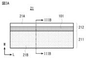
- FIG. 3A is a developed view of the positive electrode 21 and schematically represents the state before winding.
- FIG. 3B shows a cross-sectional configuration of the positive electrode 21. As shown in FIG. Note that FIG. 3B shows a cross section in the arrow direction along line IIIB-IIIB shown in FIG. 3A.
- the positive electrode 21 includes, for example, a positive electrode current collector 21A and a positive electrode active material layer 21B provided on the positive electrode current collector 21A.
- the positive electrode active material layer 21B may be provided only on one side of the positive electrode current collector 21A, or may be provided on both sides of the positive electrode current collector 21A.
- FIG. 3B shows the case where the cathode active material layer 21B is provided on both sides of the cathode current collector 21A.
- the positive electrode 21 includes a positive electrode covered portion 211 in which the positive electrode current collector 21A is covered with the positive electrode active material layer 21B, and a positive electrode exposed portion 212 in which the positive electrode current collector 21A is exposed without being covered with the positive electrode active material layer 21B. and As shown in FIG. 3A, the positive electrode covered portion 211 and the positive electrode exposed portion 212 extend from the innermost peripheral end to the outermost peripheral end of the electrode wound body 20 along the L-axis direction, which is the longitudinal direction. extended. The positive electrode covered portion 211 and the positive electrode exposed portion 212 are adjacent to each other in the W-axis direction, which is the lateral direction. In addition, the positive electrode exposed portion 212 is connected to the positive electrode collector plate 24 as shown in FIG.
- An insulating layer 101 may be provided in the vicinity of the positive electrode covered portion 211 and the positive electrode exposed portion 212 . It is preferable that the insulating layer 101 also extends from the innermost peripheral end of the electrode wound body 20 to the outermost peripheral end, similarly to the positive electrode covering portion 211 and the positive electrode exposing portion 212 . A detailed configuration of the positive electrode 21 will be described later.
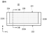
- FIG. 4A is a developed view of the negative electrode 22 and schematically shows the state before winding.
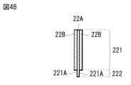
- FIG. 4B shows the cross-sectional configuration of the negative electrode 22 . Note that FIG. 4B represents a cross section in the arrow direction along line IVB-IVB shown in FIG. 4A.
- the negative electrode 22 includes, for example, a negative electrode current collector 22A and a negative electrode active material layer 22B provided on the negative electrode current collector 22A.
- the negative electrode active material layer 22B may be provided only on one side of the negative electrode current collector 22A, or may be provided on both sides of the negative electrode current collector 22A.
- FIG. 4B shows the case where the negative electrode active material layer 22B is provided on both sides of the negative electrode current collector 22A.
- the negative electrode 22 includes a negative electrode covered portion 221 in which the negative electrode current collector 22A is covered with the negative electrode active material layer 22B, and a negative electrode exposed portion 222 in which the negative electrode current collector 22A is exposed without being covered with the negative electrode active material layer 22B. and As shown in FIG. 4A, the negative electrode covered portion 221 and the negative electrode exposed portion 222 each extend along the L-axis direction, which is the longitudinal direction. The negative electrode exposed portion 222 extends from the innermost peripheral end of the electrode winding body 20 to the outermost peripheral end. On the other hand, the negative electrode covering portion 221 is not provided at the innermost peripheral end portion and the outermost peripheral end portion of the electrode wound body 20 . As shown in FIG.
- the negative electrode exposed portion 222 includes a first portion 222A, a second portion 222B, and a third portion 222C.
- the first portion 222A is provided so as to be adjacent to the negative electrode coating portion 221 in the W-axis direction, and extends in the L-axis direction from the innermost peripheral end portion of the electrode wound body 20 to the outermost peripheral end portion.
- the second portion 222B and the third portion 222C are provided so as to sandwich the negative electrode covering portion 221 in the L-axis direction.
- the second portion 222B is located, for example, near the innermost end of the electrode wound body 20, and the third portion 222C is located near the outermost end of the electrode wound body 20.
- the first portion 222 A of the negative electrode exposed portion 222 is connected to the negative electrode current collector plate 25 .
- a detailed configuration of the negative electrode 22 will be described later.
- the laminated structure S20 of the electrode wound body 20 is such that the positive electrode exposed portion 212 and the first portion 222A of the negative electrode exposed portion 222 are oriented in opposite directions along the W-axis direction, which is the width direction.
- a positive electrode 21 and a negative electrode 22 are laminated with a separator 23 interposed therebetween.
- A>B where A is the width of the positive electrode exposed portion 212 and B is the width of the first portion 222A of the negative electrode exposed portion 222.
- A 7 (mm)
- width B 4 (mm).
- the width of the portion of the positive electrode exposed portion 212 that protrudes from the outer edge of the separator 23 in the width direction is C
- the first portion 222A of the negative electrode exposed portion 222 protrudes from the outer edge of the opposite side of the separator 23 in the width direction.
- a plurality of adjacent positive electrode exposed portions 212 in the radial direction (R direction) of the electrode wound body 20 are wound around the central axis CL.
- the first edges 212E are bent toward the central axis CL so as to overlap each other.
- the radial direction (R direction) of the second edge portions 222E adjacent to each other overlaps the central axis CL. Therefore, a plurality of first edge portions 212E of the positive electrode exposed portion 212 are gathered at the upper end surface 41 of the electrode wound body 20, and the lower end surface 42 of the electrode wound body 20 is bent toward CL.
- a plurality of second edge portions 222E of the negative electrode exposed portion 222 In order to improve the contact between the positive current collecting plate 24 for extracting current and the first edge portion 212E, the second edge portion 222E is bent toward the central axis CL. A plurality of first edge portions 212E are formed to have a flat surface. The plurality of second edge portions 222E that are bent toward each other form a flat surface, and the term “flat surface” as used herein means not only a completely flat surface, but also the positive electrode exposed portion 212 and the negative electrode exposed portion 222, respectively. It also includes a surface having some unevenness or surface roughness to the extent that it can be bonded to the current collector plate 24 and the negative electrode current collector plate 25 .
- the positive electrode current collector 21A is made of, for example, aluminum foil as described later.
- the negative electrode current collector 22A is made of copper foil, for example, as described later.
- the positive electrode current collector 21A is softer than the negative electrode current collector 22A. That is, the Young's modulus of the positive electrode exposed portion 212 is lower than that of the negative electrode exposed portion 222 . Therefore, in one embodiment, A>B and C>D are more preferred. In that case, when the positive electrode exposed portion 212 and the negative electrode exposed portion 222 are bent at the same time from both electrode sides with the same pressure, the height of the bent portion measured from the tip of the separator 23 is about the same for the positive electrode 21 and the negative electrode 22. can be.
- the plurality of first edge portions 212E (FIG. 1) of the positive electrode exposed portion 212 are bent and appropriately overlapped. Therefore, the positive electrode exposed portion 212 and the positive electrode collector plate 24 can be easily joined.
- the plurality of second edge portions 222E (FIG. 1) of the negative electrode exposing portion 222 are bent and appropriately overlapped. Therefore, the bonding between the negative electrode exposed portion 222 and the negative electrode current collector plate 25 can be easily performed.
- Joining means joining by laser welding, for example, but the joining method is not limited to laser welding.
- the portion facing the negative electrode 22 with the separator 23 interposed therebetween is covered with the insulating layer 101 .
- the insulating layer 101 has a width of, for example, 3 mm in the W-axis direction.
- the insulating layer 101 covers the entire region of the positive electrode exposed portion 212 of the positive electrode 21 facing the negative electrode covering portion 221 of the negative electrode 22 with the separator 23 interposed therebetween.
- the insulating layer 101 can effectively prevent an internal short circuit of the secondary battery 1 when, for example, a foreign object enters between the negative electrode covered portion 221 and the positive electrode exposed portion 212 .
- Insulating layer 101 also absorbs impact when secondary battery 1 is impacted, effectively preventing bending of positive electrode exposed portion 212 and short-circuiting between positive electrode exposed portion 212 and negative electrode 22 . can be prevented.
- Secondary battery 1 may further have insulating tapes 53 and 54 in the gap between outer can 11 and electrode winding body 20 .
- the positive electrode exposed portion 212 and the negative electrode exposed portion 222 gathered on the end surfaces 41 and 42 are conductors such as bare metal foil. Therefore, when the positive electrode exposed portion 212 and the negative electrode exposed portion 222 are close to the outer can 11 , a short circuit between the positive electrode 21 and the negative electrode 22 may occur through the outer can 11 .
- insulating tapes 53 and 54 may be provided as insulating members.
- the insulating tapes 53 and 54 are, for example, adhesive tapes having a substrate layer made of any one of polypropylene, polyethylene terephthalate, and polyimide, and having an adhesive layer on one surface of the substrate layer.
- the insulating tapes 53 and 54 are arranged so as not to overlap the fixing tape 46 attached to the side surface portion 45 . is set equal to or less than the thickness of the fixing tape 46 .
- a structure in which leads for current extraction are welded to one positive electrode and two negative electrodes, respectively, or one current extraction lead for each of the positive electrode and the negative electrode For example, a structure in which leads are welded is adopted. A lead is also called a tab.
- the internal resistance of the lithium-ion secondary battery is large, and the lithium-ion secondary battery generates heat during charging and discharging, resulting in a high temperature, which is not suitable for high-rate charging and discharging.
- the positive electrode collector plate 24 is arranged on the end face 41 and the negative electrode collector plate 25 is arranged on the end face 42 , and the positive electrode exposed portion 212 and the positive electrode collector existing on the end face 41 are arranged.
- the plate 24 is welded at multiple points, and the negative electrode exposed portion 222 present on the end face 42 and the negative electrode collector plate 25 are also welded at multiple points. By doing so, the internal resistance of the secondary battery 1 is reduced.
- the fact that the end surfaces 41 and 42 are flat as described above also contributes to the low resistance.
- the positive electrode collector plate 24 is electrically connected to the battery cover 14 via a safety valve mechanism 30, for example.
- the negative collector plate 25 is electrically connected to the outer can 11, for example.
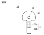
- FIG. 5A is a schematic diagram showing one configuration example of the positive electrode current collector plate 24 .
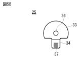
- FIG. 5B is a schematic diagram showing one configuration example of the negative electrode current collector plate 25 .
- the positive electrode collector plate 24 is a metal plate made of, for example, aluminum or an aluminum alloy alone, or a composite material thereof.
- the negative electrode current collector plate 25 is a metal plate made of, for example, nickel, a nickel alloy, copper, a copper alloy, or a composite of two or more of them.
- the positive electrode current collector plate 24 has a shape in which a substantially rectangular strip-shaped portion 32 is connected to a substantially fan-shaped fan-shaped portion 31 .
- a through hole 35 is formed near the center of the fan-shaped portion 31 .
- the positive electrode current collector plate 24 is provided such that the through hole 35 overlaps the through hole 26 in the Z-axis direction.
- the hatched portion in FIG. 5A is the insulating portion 32A of the band-shaped portion 32.
- the insulating portion 32A is a part of the belt-like portion 32 and is a portion to which an insulating tape is attached or an insulating material is applied.
- a portion of the band-shaped portion 32 below the insulating portion 32A is a connecting portion 32B to the sealing plate, which also serves as an external terminal.
- the strip-shaped portion 32 may come into contact with the portion of the negative electrode potential. low. Therefore, the positive current collecting plate 24 does not have to have the insulating portion 32A.
- the charge/discharge capacity can be increased by widening the width between the positive electrode 21 and the negative electrode 22 by an amount corresponding to the thickness of the insulating portion 32A.
- the shape of the negative electrode current collector plate 25 shown in FIG. 5B is almost the same as the shape of the positive electrode current collector plate 24 shown in FIG. 5A.
- the strip-shaped portion 34 of the negative electrode current collector plate 25 is different from the strip-shaped portion 32 of the positive electrode current collector plate 24 .
- the strip portion 34 of the negative electrode current collector plate 25 is shorter than the strip portion 32 of the positive electrode current collector plate 24 and does not have a portion corresponding to the insulating portion 32A of the positive electrode current collector plate 24 .
- the band-shaped portion 34 is provided with a plurality of round protrusions 37 indicated by circles. During resistance welding, current concentrates on the protrusion 37 , melting the protrusion 37 and welding the belt-like portion 34 to the bottom of the outer can 11 .
- the negative collector plate 25 has a through hole 36 near the center of the fan-shaped portion 33 .
- the negative electrode current collector plate 25 is provided such that the through hole 36 overlaps the through hole 26 in the Z-axis direction.
- the fan-shaped portion 31 of the positive electrode current collector plate 24 covers only part of the end surface 41 due to its planar shape.
- the fan-shaped portion 33 of the negative electrode current collector plate 25 covers only a portion of the end surface 42 due to its planar shape.
- the fan-shaped portion 31 and the fan-shaped portion 33 do not cover the entire end surface 41 and the end surface 42, for example. Firstly, it is for allowing the electrolytic solution to smoothly permeate the wound electrode body 20 when the secondary battery 1 is assembled, for example. Second, it facilitates the release of gas generated when the lithium ion secondary battery is in an abnormally high temperature state or an overcharged state.
- the positive electrode current collector 21A contains, for example, a conductive material such as aluminum.
- the positive electrode current collector 21A is, for example, a metal foil made of aluminum or an aluminum alloy.
- the positive electrode active material layer 21B contains, as a positive electrode active material, one or more of positive electrode materials capable of intercalating and deintercalating lithium. However, the positive electrode active material layer 21B may further contain one or more of other materials such as a positive electrode binder and a positive electrode conductor.
- the positive electrode material is preferably a lithium-containing compound, more specifically a lithium-containing composite oxide, a lithium-containing phosphate compound, and the like.
- a lithium-containing composite oxide is an oxide containing lithium and one or more other elements, ie, elements other than lithium, as constituent elements.
- the lithium-containing composite oxide has, for example, a layered rock salt type crystal structure, a spinel type crystal structure, or the like.
- a lithium-containing phosphate compound is a phosphate compound containing lithium and one or more other elements as constituent elements, and has, for example, an olivine-type crystal structure.
- the positive electrode active material layer 21B preferably contains at least one of lithium cobalt oxide, lithium nickel cobalt manganese oxide, and lithium nickel cobalt aluminum oxide as a positive electrode active material.
- the positive electrode binder contains, for example, one or more of synthetic rubbers and polymer compounds. Synthetic rubbers include, for example, styrene-butadiene-based rubber, fluorine-based rubber, and ethylene propylene diene. Polymer compounds include, for example, polyvinylidene fluoride and polyimide.
- the positive electrode conductor contains, for example, one or more of carbon materials. Examples of this carbon material include graphite, carbon black, acetylene black, and ketjen black. However, the positive electrode conductor may be a metal material, a conductive polymer, or the like as long as it is
- the positive electrode active material layer 21B preferably contains a fluorine compound and a nitrogen compound.
- a positive electrode film containing a fluorine compound and a nitrogen compound is formed on the surface layer of the positive electrode active material layer 21B.
- the weight ratio F/N of the fluorine content to the nitrogen content in the positive electrode film of the positive electrode active material layer 21B is preferably 3 or more and 50 or less.
- the weight ratio F/N of the fluorine content to the nitrogen content in the positive electrode film of the positive electrode active material layer 21B is preferably 15 or more and 35 or less.
- the weight ratio F/N of the fluorine content to the nitrogen content in the positive electrode film of the positive electrode active material layer 21B is, for example, the spectrum peak area of the 1s orbital of nitrogen atoms measured by X-ray photoelectron spectroscopy and the fluorine atom is calculated based on the spectral peak area of the 1s orbital of
- the area density of the positive electrode active material layer 21B is preferably 21.5 mg/cm 2 or more and 23.5 mg/cm 2 or less. This is because it is possible to suppress the temperature rise of the secondary battery 1 during high load rate charging. Furthermore, as shown in FIG. 3B, the thickness T2 of the positive electrode covering portion 211 with respect to the thickness T1 of the positive electrode current collector 21A, that is, the total thickness T2 of the positive electrode current collector 21A and the positive electrode active material layer 21B The ratio T2/T1 is preferably 5.0 or more and 6.5 or less.
- the negative electrode current collector 22A contains, for example, a conductive material such as copper.
- the negative electrode current collector 22A is, for example, a metal foil made of nickel, nickel alloy, copper, or copper alloy.
- the negative electrode active material layer 22B contains, as a negative electrode active material, one or more of negative electrode materials capable of intercalating and deintercalating lithium. However, the negative electrode active material layer 22B may further contain one or more of other materials such as a negative electrode binder and a negative electrode conductor.
- the negative electrode material is, for example, a carbon material. This is because a high energy density can be stably obtained because the crystal structure changes very little during lithium absorption and desorption.
- the carbon material also functions as a negative electrode conductor, which improves the conductivity of the negative electrode active material layer 22B. Examples of carbon materials include graphitizable carbon, non-graphitizable carbon and graphite.
- the interplanar spacing of (002) planes in the non-graphitizable carbon is preferably 0.37 nm or more.
- the interplanar spacing between (002) planes in graphite is preferably 0.34 nm or less.
- carbon materials include, for example, pyrolytic carbons, cokes, glassy carbon fibers, organic polymer compound sintered bodies, activated carbon and carbon blacks.
- the cokes include pitch coke, needle coke and petroleum coke.
- the baked organic polymer compound is obtained by baking (carbonizing) a polymer compound such as phenolic resin and furan resin at an appropriate temperature.
- the carbon material may be low-crystalline carbon heat-treated at a temperature of about 1000° C. or less, or amorphous carbon.
- the shape of the carbon material may be fibrous, spherical, granular, or scaly.
- the open circuit voltage at full charge that is, the battery voltage is 4.25 V or higher
- the same positive electrode active material is used as compared with the case where the open circuit voltage at full charge is 4.20 V.
- the amount of released lithium per unit mass increases. Therefore, the amounts of the positive electrode active material and the negative electrode active material are adjusted accordingly. This provides a high energy density.
- the negative electrode active material layer 22B may contain, as a negative electrode active material, a silicon-containing material containing at least one of silicon, silicon oxide, carbon-silicon compound, and silicon alloy.
- a silicon-containing material is a general term for materials containing silicon as a constituent element. However, the silicon-containing material may contain only silicon as a constituent element. The number of types of silicon-containing material may be one, or two or more.
- the silicon-containing material is capable of forming an alloy with lithium, and may be a simple substance of silicon, an alloy of silicon, a compound of silicon, a mixture of two or more of them, or one of them. Alternatively, it may be a material containing two or more phases.
- the silicon-containing material may be crystalline, amorphous, or contain both crystalline and amorphous portions.
- the simple substance described here means a general simple substance, it may contain a trace amount of impurities. That is, the purity of the simple substance is not necessarily limited to 100%.
- the alloy of silicon contains, for example, any one of tin, nickel, copper, iron, cobalt, manganese, zinc, indium, silver, titanium, germanium, bismuth, antimony and chromium as constituent elements other than silicon, or Contains two or more.
- the compound of silicon contains, for example, one or more of carbon and oxygen as constituent elements other than silicon.
- the compound of silicon may contain, for example, one or more of the series of constituent elements described with respect to the alloy of silicon, as constituent elements other than silicon.
- silicon alloys and silicon compounds include, for example, SiB 4 , SiB 6 , Mg 2 Si, Ni 2 Si, TiSi 2 , MoSi 2 , CoSi 2 , NiSi 2 , CaSi 2 , CrSi 2 , Cu 5 Si, FeSi2 , MnSi2 , NbSi2 , TaSi2, VSi2 , WSi2 , ZnSi2 , SiC , Si3N4 , Si2N2O and SiOv (0 ⁇ v ⁇ 2).
- the range of v can be set arbitrarily, and may be, for example, 0.2 ⁇ v ⁇ 1.4.
- the negative electrode active material layer 22B preferably contains a fluorine compound and a nitrogen compound.
- a negative electrode film containing a fluorine compound and a nitrogen compound is formed on the surface layer of the negative electrode active material layer 22B.
- the weight ratio F/N of the fluorine content to the nitrogen content in the negative electrode film of the negative electrode active material layer 22B is preferably 1 or more and 30 or less.
- the weight ratio F/N of the fluorine content to the nitrogen content in the negative electrode film of the negative electrode active material layer 22B is preferably 5 or more and 15 or less.
- the weight ratio F/N of the fluorine content to the nitrogen content in the negative electrode coating of the negative electrode active material layer 22B is, for example, the spectrum peak area of the 1s orbital of nitrogen atoms measured by X-ray photoelectron spectroscopy and the fluorine atom is calculated based on the spectral peak area of the 1s orbital of
- Separator 23 is interposed between positive electrode 21 and negative electrode 22 .
- the separator 23 allows lithium ions to pass through while preventing current short-circuiting caused by contact between the positive electrode 21 and the negative electrode 22 .
- the separator 23 is, for example, one or more of porous films such as synthetic resin and ceramic, and may be a laminated film of two or more porous films.
- Synthetic resins include, for example, polytetrafluoroethylene, polypropylene and polyethylene.
- the separator 23 may include, for example, the porous film as the substrate layer described above and a polymer compound layer provided on one or both sides of the substrate layer.
- the polymer compound layer contains polymer compounds such as polyvinylidene fluoride, for example. This is because it has excellent physical strength and is electrochemically stable. However, the polymer compound may be other than polyvinylidene fluoride.
- this polymer compound layer When forming this polymer compound layer, for example, a solution in which a polymer compound is dissolved in an organic solvent or the like is applied to the substrate layer, and then the substrate layer is dried. The base layer may be dried after the base layer is immersed in the solution.
- This polymer compound layer may contain, for example, one or more of insulating particles such as inorganic particles. Types of inorganic particles include, for example, aluminum oxide and aluminum nitride.
- the electrolyte contains a solvent and an electrolyte salt. However, the electrolytic solution may further contain one or more of other materials such as additives.
- the solvent contains one or more of non-aqueous solvents such as organic solvents.
- An electrolytic solution containing a non-aqueous solvent is a so-called non-aqueous electrolytic solution.
- Non-aqueous solvents include, for example, fluorine compounds and nitrile compounds.
- the fluorine compound includes, for example, at least one of fluorinated ethylene carbonate, trifluorocarbonate, trifluoroethylmethyl carbonate, fluorinated carboxylic acid ester, and fluorine ether.
- the nitrile compound includes, for example, at least one of a mononitrile compound, a dinitrile compound, and a tritrile compound. Succinonitrile (SN), for example, is preferred as the nitrile compound.
- the electrolyte salt includes, for example, one or more of salts such as lithium salt.
- the electrolyte salt may contain, for example, a salt other than the lithium salt.
- This non-lithium salt is, for example, a light metal salt other than lithium.
- Lithium salts include, for example, lithium hexafluorophosphate (LiPF 6 ), lithium tetrafluoroborate (LiBF 4 ), lithium perchlorate (LiClO 4 ), lithium hexafluoroarsenate (LiAsF 6 ), tetraphenyl lithium borate (LiB( C6H5 ) 4 ) , lithium methanesulfonate (LiCH3SO3) , lithium trifluoromethanesulfonate ( LiCF3SO3 ) , lithium tetrachloroaluminate ( LiAlCl4 ), hexafluoride These include dilithium silicate (Li 2 SF 6 ), lithium chloride (LiCl) and lithium bromide (LiBr).
- LiPF 6 lithium hexafluorophosphate
- LiBF 4 lithium perchlorate
- LiAsF 6 lithium hexafluoroarsenate
- lithium hexafluorophosphate lithium tetrafluoroborate, lithium perchlorate and lithium hexafluoroarsenate are preferable, and lithium hexafluorophosphate is more preferable.
- the content of the electrolyte salt is not particularly limited, it is preferably from 0.3 mol/kg to 3 mol/kg of the solvent.
- the concentration of LiPF 6 in the electrolyte is preferably 1.25 mol/kg or more and 1.45 mol/kg or less. This is because cycle deterioration due to consumption (decomposition) of salt during high load rate charging can be prevented, thereby improving high load cycle characteristics.
- the concentration of LiBF 4 in the electrolyte is preferably 0.001 (% by weight) or more and 0.1 (% by weight) or less. This is because it is possible to more effectively prevent cycle deterioration due to salt consumption (decomposition) during high-load-rate charging, thereby further improving high-load cycle characteristics.
- the positive electrode current collector 21A is prepared, and the positive electrode 21 having the positive electrode covering portion 211 and the positive electrode exposed portion 212 is formed by selectively forming the positive electrode active material layer 21B on the surface of the positive electrode current collector 21A.
- the negative electrode current collector 22A is prepared, and the negative electrode 22 having the negative electrode covering portion 221 and the negative electrode exposed portion 222 is formed by selectively forming the negative electrode active material layer 22B on the surface of the negative electrode current collector 22A. .
- cutouts are formed in portions of the positive electrode exposed portion 212 and the negative electrode exposed portion 222 which correspond to the beginning of winding.
- a drying process may be performed on the positive electrode 21 and the negative electrode 22 .
- the positive electrode 21 and the negative electrode 22 are stacked with the separator 23 interposed therebetween so that the positive electrode exposed portion 212 and the first portion 222A of the negative electrode exposed portion 222 are opposite to each other in the W-axis direction, thereby forming the laminate structure S20. make.
- the laminated structure S20 is spirally wound such that the through hole 26 is formed and the notch is arranged near the central axis CL.
- a fixing tape 46 is attached to the outermost periphery of the spirally wound laminated structure S20.
- the electrode winding body 20 is obtained as shown in FIG. 6(A).
- substantially the same pressure is applied substantially simultaneously from above and below the electrode winding body 20 to the end face 41 and the end face 42 in a substantially vertical direction.
- the positive electrode exposed portion 212 and the first portion 222A of the negative electrode exposed portion 222 are each bent so that the end surface 41 and the end surface 42 are flat surfaces.
- the first edge portion 212E of the positive electrode exposed portion 212 and the second edge portion 222E of the negative electrode exposed portion 222 on the end face 41 and the end face 42 are bent while overlapping toward the through hole 26 .
- the fan-shaped portion 31 of the positive electrode collector plate 24 is joined to the end face 41 by laser welding or the like, and the fan-shaped portion 33 of the negative electrode collector plate 25 is joined to the end face 42 by laser welding or the like.
- the insulating tapes 53 and 54 are attached to predetermined positions of the electrode winding body 20 .
- the strip-shaped portion 32 of the positive electrode current collector plate 24 is bent, and the strip-shaped portion 32 is inserted through the hole 12H of the insulating plate 12 .
- the belt-shaped portion 34 of the negative electrode current collector plate 25 is bent, and the belt-shaped portion 34 is inserted through the hole 13 ⁇ /b>H of the insulating plate 13 .
- the electrolyte contains LiPF 6 as a lithium salt, and the concentration of LiPF 6 in the electrolyte is 1.25 mol/kg or more and 1.45 mol/kg or less. is configured to If the electrolyte salt concentration is 1.25 mol/kg or more, a sufficient number of ion carriers can be obtained, so an increase in resistance can be avoided and heat generation can be effectively reduced.
- the concentration of the electrolyte salt is 1.45 mol/kg or less, the viscosity increase of the electrolyte solution due to the presence of the electrolyte salt can be suppressed, the impregnation of the positive electrode 21 and the negative electrode 22 can be maintained well, and heat generation can be effectively performed. can be reduced to Therefore, the secondary battery 1 can moderate the internal temperature rise during charging, and can effectively suppress the decomposition reaction of the electrolytic solution. Therefore, cycle deterioration due to salt consumption (decomposition) during high load rate charging can be prevented, and high load cycle characteristics are improved. Therefore, high reliability can be achieved.
- the secondary battery 1 of the present embodiment can suppress the decomposition reaction of the electrolyte salt in the electrolytic solution, thereby obtaining excellent cycle characteristics. That is, the secondary battery 1 of the present embodiment can suppress temperature rise even during high load rate charging, can exhibit excellent cycle characteristics, and can ensure higher reliability.
- the secondary battery 1 of the present embodiment is particularly suitable for applications in which high load rate charging is frequently used.
- the conventional tab structure can be used. can exhibit life characteristics that are markedly superior to those of secondary batteries.
- the secondary battery 1 further contains LiBF 4 in addition to LiPF 6 as an electrolyte salt, and the concentration of LiBF 4 in the electrolyte is 0.001 (% by weight) or more and 0.1 (% by weight) or less.
- both the positive electrode active material layer 21B and the negative electrode active material layer 22B contain a fluorine compound and a nitrogen compound.
- the weight ratio F/N of the fluorine content to the nitrogen content in the positive electrode active material layer 21B is 3 or more and 50 or less.
- the weight ratio F/N of the fluorine content to the nitrogen content in the negative electrode active material layer 22B is 1 or more and 30 or less. Therefore, a stable film is formed on each of the positive electrode 21 and the negative electrode 22 . Therefore, the decomposition reaction of the electrolytic solution is suppressed, and excellent high load cycle characteristics are obtained. Therefore, even higher reliability can be achieved.
- the weight ratio F/N contained in each of the positive electrode active material layer 21B and the negative electrode active material layer 22B is controlled within an appropriate range to control the absolute amount of the film, thereby increasing the resistance. increase can be suppressed.
- the cycle characteristics in the high output range can be further improved.
- the decomposition of the electrolytic solution Reaction is suppressed more and more excellent high load cycle characteristics are obtained. Therefore, it has higher reliability.
- FIG. 7 is a block diagram showing a circuit configuration example when a battery (hereinafter referred to as a secondary battery) according to an embodiment of the present invention is applied to the battery pack 330.
- the battery pack 300 includes an assembled battery 301 , an exterior, a switch section 304 including a charge control switch 302 a and a discharge control switch 303 a , a current detection resistor 307 , a temperature detection element 308 and a control section 310 .
- the battery pack 300 has a positive terminal 321 and a negative terminal 322.
- the positive terminal 321 and the negative terminal 322 are connected to the positive terminal and the negative terminal of the charger, respectively, and charging is performed.
- the positive terminal 321 and the negative terminal 322 are connected to the positive terminal and the negative terminal of the electronic device, respectively, and discharge is performed.
- the assembled battery 301 is formed by connecting a plurality of secondary batteries 301a in series or in parallel.
- the secondary battery 1 described above can be applied as the secondary battery 301a.
- FIG. 7 shows an example in which six secondary batteries 301a are connected in 2-parallel and 3-series (2P3S). any connection method.
- the switch section 304 includes a charge control switch 302a and a diode 302b, and a discharge control switch 303a and a diode 303b, and is controlled by the control section 310.
- the diode 302 b has a polarity opposite to the charging current flowing from the positive terminal 321 to the assembled battery 301 and forward to the discharging current flowing from the pole terminal 322 to the assembled battery 301 .
- Diode 303b has a forward polarity for charging current and a reverse polarity for discharging current. Note that although the switch unit 304 is provided on the + side in FIG. 7, it may be provided on the - side.
- the charge control switch 302a is turned off when the battery voltage reaches the overcharge detection voltage, and is controlled by the charge/discharge control unit so that the charging current does not flow through the current path of the assembled battery 301. After the charge control switch 302a is turned off, only discharging is possible through the diode 302b. Moreover, it is controlled by the control unit 310 so that it is turned off when a large current flows during charging, and the charging current flowing through the current path of the assembled battery 301 is interrupted.
- the discharge control switch 303a is turned off when the battery voltage reaches the overdischarge detection voltage, and is controlled by the controller 310 so that the discharge current does not flow through the current path of the assembled battery 301.
- the discharge control switch 303a After the discharge control switch 303a is turned off, only charging is possible through the diode 303b. Also, it is controlled by the control unit 310 so that it is turned off when a large current flows during discharge, and the discharge current flowing through the current path of the assembled battery 301 is interrupted.
- the temperature detection element 308 is, for example, a thermistor, is provided near the assembled battery 301 , measures the temperature of the assembled battery 301 and supplies the measured temperature to the control unit 310 .
- the voltage detection unit 311 measures the voltages of the battery pack 301 and the secondary batteries 301a constituting it, A/D-converts the measured voltages, and supplies the voltages to the control unit 310 .
- a current measurement unit 313 measures current using a current detection resistor 307 and supplies the measured current to the control unit 310 .
- the switch control unit 314 The charge control switch 302 a and the discharge control switch 303 a of the switch section 304 are controlled based on the voltage and current input from the voltage detection section 311 and the current measurement section 313 .
- the switch control unit 314 controls the switch unit 304 when the voltage of any one of the secondary batteries 301a falls below the overcharge detection voltage or below the overdischarge detection voltage, or when a large current suddenly flows. Overcharging, overdischarging, and overcurrent charging/discharging are prevented by sending control signals.
- the overcharge detection voltage is set at, for example, 4.20V ⁇ 0.05V
- the overdischarge detection voltage is set at, for example, 2.4V ⁇ 0.1V. .
- the parasitic diodes of the MOSFETs act as diodes 302b and 303b.
- switch control section 314 supplies control signals DO and CO to the gates of charge control switch 302a and discharge control switch 303a, respectively. If the charge control switch 302a and the discharge control switch 303a are of the P-channel type, they are turned on by a gate potential lower than the source potential by a predetermined value or more. That is, in normal charge and discharge operations, the control signals CO and DO are set to low level, and the charge control switch 302a and the discharge control switch 303a are turned on.
- control signals CO and DO are set to high level, and the charge control switch 302a and the discharge control switch 303a are turned off.
- the memory 317 consists of RAM and ROM, for example EPROM (Erasable Programmable Read Only Memory) which is a non-volatile memory.
- EPROM Erasable Programmable Read Only Memory
- the numerical value calculated by the control unit 310, the internal resistance value of each secondary battery 301a in the initial state measured in the manufacturing process, and the like are stored in advance, and can be rewritten as appropriate. . Further, by storing the full charge capacity of the secondary battery 301a, it is possible to calculate, for example, the remaining capacity together with the control unit 310.
- the temperature detection unit 318 measures the temperature using the temperature detection element 308, performs charge/discharge control when abnormal heat is generated, and corrects the calculation of the remaining capacity.
- the secondary battery according to one embodiment of the present disclosure described above can be mounted in devices such as electronic devices, electric vehicles, electric aircraft, and power storage devices, or can be used to supply electric power.
- Examples of electronic devices include notebook computers, smartphones, tablet terminals, PDAs (personal digital assistants), mobile phones, wearable terminals, cordless phone slaves, video movies, digital still cameras, electronic books, electronic dictionaries, music players, radios, Headphones, game consoles, navigation systems, memory cards, pacemakers, hearing aids, power tools, electric shavers, refrigerators, air conditioners, televisions, stereos, water heaters, microwave ovens, dishwashers, washing machines, dryers, lighting equipment, toys, medical equipment equipment, robots, road conditioners, traffic lights, etc.
- Electric vehicles include railway vehicles, golf carts, electric carts, electric vehicles (including hybrid vehicles), and the like, and are used as power sources for driving or auxiliary power sources for these vehicles.
- Power storage devices include electric power storage power sources for buildings such as houses and power generation facilities.
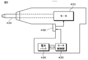
- the electric driver 431 contains a motor 433 such as a DC motor in its main body. The rotation of the motor 433 is transmitted to the shaft 434, and the shaft 434 drives the screw into the object.
- the electric driver 431 is provided with a trigger switch 432 operated by the user.
- a battery pack 430 and a motor control unit 435 are housed in the lower housing of the handle of the electric driver 431 .
- Battery pack 300 can be used as battery pack 430 .
- the motor control section 435 controls the motor 433 .
- Each part of the electric driver 431 other than the motor 433 may be controlled by the motor control part 435 .
- Battery pack 430 and electric driver 431 are engaged by engaging members provided respectively.
- each of battery pack 430 and motor control unit 435 is provided with a microcomputer. Battery power is supplied from the battery pack 430 to the motor controller 435, and information on the battery pack 430 is communicated between the microcomputers of both.
- the battery pack 430 is detachable from the electric driver 431, for example.
- Battery pack 430 may be built into electric driver 431 .
- Battery pack 430 is attached to a charging device during charging. Note that when the battery pack 430 is attached to the electric driver 431, a part of the battery pack 430 may be exposed to the outside of the electric driver 431 so that the exposed part can be visually recognized by the user. For example, an LED may be provided in the exposed portion of the battery pack 430 so that the user can check whether the LED is lit or not.
- the motor control unit 435 controls, for example, the rotation and stop of the motor 433 and the direction of rotation. Furthermore, the power supply to the load is cut off during overdischarge.
- the trigger switch 432 is inserted, for example, between the motor 433 and the motor control unit 435. When the user presses the trigger switch 432, power is supplied to the motor 433 and the motor 433 rotates. When the user releases trigger switch 432, motor 433 stops rotating.
- FIG. 9 is a plan view of an unmanned aerial vehicle.
- the base body of the unmanned aerial vehicle includes a cylindrical or rectangular tube body as a central part and support shafts 442a to 442f fixed to the upper part of the body.
- the body has a hexagonal cylindrical shape, and six support shafts 442a to 442f radially extend from the center of the body at equal angular intervals.
- the body and support shafts 442a-442f are made of lightweight and high-strength material.
- Motors 443a to 443f are attached to the tips of the support shafts 442a to 442f, respectively, as driving sources for the rotor blades.
- Rotary blades 444a to 444f are attached to the rotating shafts of the motors 443a to 443f.
- a circuit unit 445 including a motor control circuit for controlling each motor is attached to the central portion (upper portion of the body portion) where the support shafts 442a to 442f intersect.
- a battery section as a power source is arranged below the body section.
- the battery section has three battery packs to power a pair of motors and rotor blades that are 180 degrees apart.
- Each battery pack has, for example, a lithium ion secondary battery and a battery control circuit that controls charging and discharging.
- Battery pack 300 can be used as the battery pack.
- a motor 443a and a rotor blade 444a and a motor 443d and a rotor blade 444d form a pair.
- the motor 443b and the rotor 444b and the motor 443e and the rotor 444e form a pair
- the motor 443c and the rotor 444c and the motor 443f and the rotor 444f form a pair.
- An equal number of these pairs and battery packs are provided.
- FIG. 10 schematically shows an example configuration of a hybrid vehicle that employs a series hybrid system to which the secondary battery of the present disclosure is applied.
- a series hybrid system is a vehicle that runs with a power driving force conversion device using power generated by a generator driven by an engine or power temporarily stored in a battery.
- the hybrid vehicle 600 includes an engine 601, a generator 602, a power driving force converter 603, drive wheels 604a, 604b, wheels 605a, 605b, a battery 608, a vehicle control device 609, various sensors 610, and a charging port 611. is installed.
- the battery pack 300 of the present disclosure described above can be applied to the battery 608 .
- the hybrid vehicle 600 runs using the power driving force conversion device 603 as a power source.
- An example of the power driving force conversion device 603 is a motor.
- the power of the battery 608 operates the power driving force converter 603, and the rotational force of this power driving force converter 603 is transmitted to the driving wheels 604a and 604b.
- DC-AC direct current-alternating current
- AC-DC conversion inverse conversion
- the power driving force converter 603 can be applied to either an AC motor or a DC motor.
- Various sensors 610 control the engine speed via the vehicle control device 609 and control the opening of a throttle valve (not shown) (throttle opening).
- Various sensors 610 include a speed sensor, an acceleration sensor, an engine speed sensor, and the like.
- the rotational force of the engine 601 is transmitted to the generator 602, and the electric power generated by the generator 602 by the rotational force can be stored in the battery 608.
- hybrid vehicle 600 is decelerated by a braking mechanism (not shown)
- resistance during deceleration is applied to electric power driving force conversion device 603 as a rotational force, and regenerative electric power generated by electric power driving force conversion device 603 by this rotational force is supplied to battery 608.
- battery 608 By being connected to a power source external to hybrid vehicle 600, battery 608 can receive power from the external power source using charging port 611 as an input port, and store the received power.
- an information processing device that performs information processing regarding vehicle control based on information regarding the secondary battery may be provided.
- an information processing apparatus for example, there is an information processing apparatus that displays the remaining battery level based on information regarding the remaining amount of the secondary battery.
- Example 1-1 to 1-4 As described below, after the cylindrical lithium ion secondary battery shown in FIG. 1 and the like was produced, the battery characteristics of the lithium ion secondary battery were evaluated. Here, a lithium ion secondary battery having dimensions of 21 mm in diameter and 70 mm in length was produced.
- an aluminum foil having a thickness of 12 ⁇ m was prepared as the positive electrode current collector 21A.
- a positive electrode material mixture was obtained by mixing with a conductive aid mixed with chain black. The mixing ratio of the positive electrode active material, the positive electrode binder, and the conductive aid was 95:2:3.
- the positive electrode mixture was put into an organic solvent (N-methyl-2-pyrrolidone), the organic solvent was stirred to prepare a pasty positive electrode mixture slurry.
- the positive electrode mixture slurry was applied to predetermined regions on both surfaces of the positive electrode current collector 21A using a coating device, and then the positive electrode mixture slurry was dried to form the positive electrode active material layer 21B.
- Insulating layer 101 having a width of 3 mm was formed by applying a paint containing polyvinylidene fluoride (PVDF) to a portion adjacent to positive electrode covered portion 211 on the surface of positive electrode exposed portion 212 and drying the paint. After that, the positive electrode active material layer 21B was compression-molded using a roll press machine.
- PVDF polyvinylidene fluoride
- the positive electrode 21 having the positive electrode covered portion 211 and the positive electrode exposed portion 212 was obtained.
- the width of the positive electrode covered portion 211 in the W-axis direction was set to 60 mm
- the width of the positive electrode exposed portion 212 in the W-axis direction was set to 7 mm.
- the length of the positive electrode 21 in the L-axis direction was set to 1700 mm.
- the area density of the cathode active material layer 21B was 22.0 mg/cm 2 and the volume density of the cathode active material layer 21B was 3.55 mg/cm 3 .
- the thickness T1 of the positive electrode covering portion 211 was 62.0 ⁇ m. Therefore, the ratio T2/T1 of the thickness T2 of the positive electrode current collector 21A to the thickness T1 of the positive electrode covering portion 211 was 5.17.
- a copper foil with a thickness of 8 ⁇ m was prepared as the negative electrode current collector 22A.
- a negative electrode active material in which a carbon material made of graphite and SiO are mixed, a negative electrode binder made of polyvinylidene fluoride, and a conductive aid in which carbon black, acetylene black, and ketjen black are mixed are mixed.
- a negative electrode mixture was obtained by mixing.
- the mixing ratio of the negative electrode active material, the negative electrode binder, and the conductive aid was 95:3.5:1.5. Further, the mixing ratio of graphite and SiO in the negative electrode active material was set to 95:5.
- the negative electrode mixture was put into an organic solvent (N-methyl-2-pyrrolidone), the organic solvent was stirred to prepare a pasty negative electrode mixture slurry.
- the negative electrode mixture slurry was applied to predetermined regions on both surfaces of the negative electrode current collector 22A using a coating device, and then the negative electrode mixture slurry was dried to form the negative electrode active material layer 22B.
- the negative electrode active material layer 22B was compression molded using a roll press. As described above, the negative electrode 22 having the negative electrode covering portion 221 and the negative electrode exposed portion 222 was obtained.
- the width of the negative electrode covering portion 221 in the W-axis direction was set to 62 mm, and the width of the first portion 222A of the negative electrode exposed portion 222 in the W-axis direction was set to 4 mm. Also, the length of the negative electrode 22 in the L-axis direction was set to 1760 mm.
- the positive electrode 21 and the negative electrode 22 are stacked with the separator 23 interposed therebetween so that the positive electrode exposed portion 212 and the first portion 222A of the negative electrode exposed portion 222 are opposite to each other in the W-axis direction, thereby forming the laminate structure S20. made.
- the laminated structure S20 was produced so that the positive electrode active material layer 21B did not protrude from the negative electrode active material layer 22B in the W-axis direction.
- a polyethylene sheet having a width of 65 mm and a thickness of 14 ⁇ m was used as the separator 23 .
- the laminated structure S20 was spirally wound so that the through hole 26 was formed and the notch was arranged near the central axis CL, and the fixing tape 46 was attached to the outermost circumference of the wound laminated structure S20.
- the electrode winding body 20 was obtained.
- substantially simultaneously and substantially the same pressure is applied to the end surface 41 and the end surface 42 from above and below the electrode wound body 20 in a substantially vertical direction, thereby exposing the positive electrode exposed portion 212 and the negative electrode exposed portion 222 .
- the first portion 222A thereof were bent to form the end faces 41 and 42 into flat faces.
- the first edge portion 212E of the positive electrode exposed portion 212 and the second edge portion 222E of the negative electrode exposed portion 222 on the end face 41 and the end face 42 were bent while overlapping toward the through hole 26 .
- the fan-shaped portion 31 of the positive electrode current collector plate 24 was joined to the end surface 41 by laser welding, and the fan-shaped portion 33 of the negative electrode current collector plate 25 was joined to the end surface 42 by laser welding.
- the strip-shaped portion 32 of the positive electrode current collector plate 24 is bent to insert the strip-shaped portion 32 into the hole 12H of the insulating plate 12,
- the belt-shaped portion 34 of the negative electrode current collector plate 25 was bent and inserted into the hole 13 ⁇ /b>H of the insulating plate 13 .
- the electrolyte contains ethylene carbonate (EC) and dimethyl carbonate (DMC) as the main solvents, fluoroethylene carbonate (FEC) and succinonitrile (SN) added, and LiBF4 and LiPF6 as electrolyte salts. used things.
- EC ethylene carbonate
- DMC dimethyl carbonate
- FEC fluoroethylene carbonate
- SN succinonitrile
- LiBF4 and LiPF6 electrolyte salts. used things.
- the concentration of the electrolyte salt is defined as the ratio (mol/kg) of the total weight of LiBF 4 and LiPF 6 to the total weight of cyclic carbonate and chain carbonate whose weight ratio is 5% or more in the electrolytic solution. Calculated.
- the ratio (mol/kg) of the total weight of LiBF 4 and LiPF 6 to the total weight of EC, DMC and FEC in the electrolytic solution was calculated.
- the content of each component in the electrolyte solution was adjusted so that the electrolyte salt concentration was in the range of 1.25 mol/kg to 1.45 mol/kg.
- the concentration of LiBF 4 in the electrolytic solution was set to 0.1% by weight or less.
- the electrolytic solution was collected by making a cut in the bottom of the outer can 11 and performing centrifugal separation.
- the P element and the Li element were quantified by the ICP analysis method for the sampled electrolytic solution diluted with an aqueous nitric acid solution. Furthermore, the contents of each of EC, DMC, FEC, and SN in the diluted electrolyte were calculated by gas chromatography.
- the absolute amount of the coating of the positive electrode active material layer 21B and the coating of the negative electrode active material layer 22B changes depending on the added amounts of FEC and SN and the conditions of the coating forming process.
- the absolute amount of the film and the weight ratio F /N was fine-tuned.
- the battery voltage was set to 3.4 V to 3.6 V
- the ambient temperature was set to 60° C.
- the holding time was set to 3 hours to 20 hours. have been fine-tuned.
- the weight ratio F/N of the positive electrode active material layer 21B was set to 25, and the weight ratio F/N of the negative electrode active material layer 22B was set to 10.
- the 300 cycle retention rate of 40 A is the 300 cycle retention rate when discharge is performed at a constant current of 40 A
- the 300 cycle retention rate of 10 A is the 300 cycle retention rate when discharge is performed at a constant current of 10 A. rate.
- the above constant current/constant voltage charging was performed at 6 A to 4.2 V, and then the battery was discharged to 2.0 V at 800 mA.
- Quantification of fluorine and nitrogen contained in the films of the positive electrode and the negative electrode was carried out in the following manner.
- a lithium ion secondary battery was discharged to 2.5 V at 0.2 C, then disassembled in a non-air environment, and the positive electrode and the negative electrode were taken out.
- the removed negative electrode was immersed in dimethyl carbonate (DMC) and washed.
- the positive electrode and the negative electrode were introduced into the analyzer while maintaining the non-atmospheric environment.
- a scanning X-ray photoelectron spectrometer (PHI Quantera SXM) manufactured by ULVAC-PHI was used. The measurement conditions were monochromatic Al-k ⁇ rays (1486.6 eV, beam size of about 100 ⁇ m ⁇ ).
- Comparative Examples 1-1 to 1-2 A lithium ion secondary battery was produced as a comparative example for the above example.
- the content of each component of the electrolytic solution was adjusted so that the electrolyte salt concentration was 1.24 mol/kg, and in Comparative Example 1-2, the electrolyte salt concentration was 1.46 mol/kg.
- the content of each component in the electrolytic solution was adjusted so that The battery characteristics of the lithium ion secondary batteries of Comparative Examples 1-1 to 1-2 were evaluated in the same manner as the lithium ion secondary batteries of Examples 1-1 to 1-4. The results are also shown in Table 1.
- Example 2-1 to 2-17 The electrolytic solution was adjusted so that the weight ratio F/N of the positive electrode active material layer 21B and the weight ratio F/N of the negative electrode active material layer 22B were the numerical values shown in Table 2, respectively. Except for this point, lithium ion secondary batteries of Examples 2-1 to 2-17 were produced in the same manner as in Example 1-3, and battery characteristics were evaluated in the same manner as in Example 1-3. bottom. Table 2 shows the results.
- Lithium ion secondary batteries were produced as comparative examples for Examples 2-1 to 2-17.
- the weight ratio F/N in the negative electrode active material layer was set to 0.9
- the weight ratio F/N in the negative electrode active material layer was set to 31.
- the weight ratio F/N in the positive electrode active material layer was set to 2
- the weight ratio F/N in the negative electrode active material layer was set to 51.
- the configurations of the lithium ion secondary batteries of Comparative Examples 2-1 to 2-4 were the same as those of the lithium ion secondary battery of Example 1-3 except for these points.
- the battery characteristics of the lithium ion secondary batteries of Comparative Examples 2-1 to 2-4 were also evaluated in the same manner as the lithium ion secondary battery of Example 1-3. Table 3 shows the results.
- a positive electrode exposed portion 121C in which the positive electrode current collector 121A is exposed without the positive electrode active material layer 121B being formed is provided in an intermediate portion in the L-axis direction, which is the longitudinal direction.
- a positive electrode tab 121T is attached to the positive electrode exposed portion 121C.
- the positive electrode tab 121T is electrically connected to the battery lid 14 via the safety valve mechanism 30 instead of the positive electrode collector plate 24 .
- negative electrode exposed portions 122C in which the negative electrode active material layer 122B is not formed and the negative electrode current collector 122A is exposed are provided at both ends in the L-axis direction. He is trying to attach the negative electrode tab 122T to the part 122C.
- the negative electrode tab 122T is electrically connected to the outer can 11 instead of the negative current collector plate 25 .
- the battery characteristics of the lithium ion secondary batteries of Comparative Examples 2-5 to 2-15 were evaluated in the same manner as the lithium ion secondary battery of Example 1-3. The results are also shown in Table 3.
- Examples 3-1 to 3-8) The positive electrode 21 was formed so that the area density of the positive electrode active material layer 21B and the volume density of the positive electrode active material layer 21B were the numerical values shown in Table 4, respectively. Except for this point, lithium ion secondary batteries of Examples 3-1 to 3-8 were produced in the same manner as in Example 1-3, and battery characteristics were evaluated in the same manner as in Example 1-3. bottom. Here, the area density of the positive electrode active material layer 21B was adjusted by changing the application amount of the slurry applied to the positive electrode current collector 21A. Further, the volume density of the positive electrode active material layer 21B was controlled by changing the pressing force of the roll press. The lithium ion secondary batteries of Examples 3-1 to 3-8 were also evaluated for 500 cycle retention rate and surface temperature.
- a first stage charging operation of charging to a voltage of 4.0 V at a constant current of 3 C, followed by a second stage charging operation of charging to a voltage of 4.2 V at a constant current of 1 C. and a discharge operation of discharging to a voltage of 2.5 V at a constant current of 30 A were defined as one cycle, and this was repeated 500 cycles.
- the ratio of the discharge capacity at the 500th cycle to the discharge capacity at the 1st cycle was calculated, and the value was taken as the cycle retention rate.
- the surface temperature the temperature of the surface of the outer can 11 was measured for the lithium ion secondary battery after 500 cycles.
- the temperature of the surface of the outer can 11 was measured by attaching a thermocouple to the surface of the outer can 11 . Those results are shown in Table 4.
- Example 4-1 to 4-5 were prepared in the same manner as in Example 1-3, except that the thickness of the aluminum foil as the positive electrode current collector 21A was the value shown in Table 5. Lithium ion secondary batteries were produced, respectively, and battery characteristics were evaluated in the same manner as in Examples 3-1 to 3-8. Table 5 shows the results.
- Example 5-1 to 5-3 The thickness of the positive electrode active material layer 21B is adjusted such that the thickness T2 of the positive electrode covering portion 211 is the numerical value shown in Table 6, and the volume density of the positive electrode active material layer 21B is the numerical value shown in Table 6.
- Lithium ion secondary batteries of Examples 5-1 to 5-5 were produced in the same manner as in Example 1-3, except that the thickness was adjusted, and the same as in Examples 3-1 to 3-8. was evaluated for battery characteristics. Table 6 shows the results.
- Example 6-1 to 6-4 Electrolyte solutions were adjusted so that the concentrations of the electrolyte salts were the numerical values shown in Table 7, respectively. Also, the concentration of LiBF 4 in the electrolytic solutions (EC, DMC, and FEC) was set to 0.004% by weight. Except for these points, lithium ion secondary batteries of Examples 6-1 to 6-4 and Comparative Examples 6-1 to 6-4 were produced in the same manner as in Example 1-3, and the battery characteristics were evaluated. An evaluation was carried out. Here, similarly to Examples 3-1 to 3-8, battery capacity, surface temperature, and 500 cycle retention rate were evaluated. Table 7 shows the results.
- Example 7-1 to 7-7-7 The amount of LiBF 4 added was adjusted so that the concentrations of LiBF 4 as electrolyte salts in the electrolytes (EC, DMC, and FEC) were the values shown in Table 8, respectively. Except for that point, lithium ion secondary batteries of Examples 7-1 to 7-7 were produced in the same manner as in Example 1-3, and batteries were prepared in the same manner as in Examples 3-1 to 3-8. Capacity, surface temperature, and 500 cycle retention rate were evaluated. Table 7 shows the results.
- the thickness of the positive electrode covering portion 211 with respect to the thickness T1 of the positive electrode current collector 21A When the thickness T2, that is, the ratio T2/T1 of the total thickness T2 of the positive electrode current collector 21A and the positive electrode active material layer 21B is 5.0 or more and 6.5 or less, the rise in surface temperature is suppressed and It was confirmed that sufficient battery capacity and better cycle characteristics could be obtained.
- Example 6 from a comparison of Example 1-3 and Examples 5-1 to 5-2 with Comparative Examples 5-1, 5-2 and Example 5-3, the volume density was It was confirmed that when the content is 3.55 mg/cm 3 or less, a sufficient battery capacity and better cycle characteristics can be obtained while suppressing an increase in surface temperature. In addition, in Comparative Examples 5-1 and 5-2, the volume density was too high and electrodes could not be produced.
- the concentration of LiBF 4 in the electrolytic solution was 0.001 (% by weight). It has been confirmed that when the content is 0.10 (% by weight) or less, a sufficient battery capacity and better cycle characteristics can be obtained while suppressing an increase in surface temperature.
- the electrode reactant is lithium, but the electrode reactant is not particularly limited.
- the electrode reactants may be other alkali metals such as sodium and potassium, or alkaline earth metals such as beryllium, magnesium and calcium, as described above.
- the electrode reactant may be other light metals such as aluminum.
Landscapes
- Chemical & Material Sciences (AREA)
- Chemical Kinetics & Catalysis (AREA)
- Electrochemistry (AREA)
- General Chemical & Material Sciences (AREA)
- Engineering & Computer Science (AREA)
- Manufacturing & Machinery (AREA)
- Inorganic Chemistry (AREA)
- General Physics & Mathematics (AREA)
- Condensed Matter Physics & Semiconductors (AREA)
- Physics & Mathematics (AREA)
- Materials Engineering (AREA)
- Composite Materials (AREA)
- Aviation & Aerospace Engineering (AREA)
- Microelectronics & Electronic Packaging (AREA)
- Secondary Cells (AREA)
Abstract
Description
0.経緯
1.二次電池
1-1.構成
1-2.動作
1-3.製造方法
1-4.作用および効果
2.応用例
従来、電池素子を構成する正極および負極とそれぞれ電気的に接続された、電流取り出し用の正極端子(正極タブ)および負極端子(負極タブ)を有する二次電池が広く用いられている。ここではタブ構造の二次電池と呼ぶ。しかしながら、一般に、タブ構造の二次電池では正極端子や負極端子が短冊状の細長い形状を有しており、正極端子と正極との接続箇所の面積や負極端子と負極との接続箇所の面積は狭い。そのため、それらの接続箇所における電気抵抗が高くなり、結果として電池の内部抵抗の増加の原因となり得る。近年
、より高い負荷レートでの充放電が求められつつある。ところがタブ構造の二次電池では、高負荷レートでの充電を行うと、内部抵抗が大きいことから電池内部の温度が上昇しやすい。電池内部に電解質塩として含まれるリチウム塩は、高温環境下で分解しやすい特性を有する。したがって、電池温度の上昇に伴い、電解液中のリチウム塩の分解反応が進んでイオンのキャリアが減少すると、二次電池の内部抵抗がさらに上昇する。その結果、二次電池の発熱量が増大するため、二次電池の温度はますます上昇し、リチウム塩の分解反応もさらに進行するという、悪循環を招く可能性が懸念される。
まず、本開示の一実施形態の二次電池に関して説明する。
(リチウムイオン二次電池1)
図1は、本実施の形態のリチウムイオン二次電池1(以下、単に二次電池1という。)の断面構成を表している。図1に示した二次電池1では、円筒状の外装缶11の内部に電
池素子としての電極巻回体20が収納されている。
外装缶11は、例えば、高さ方向であるZ軸方向の下端部が閉鎖されると共に上端部が開放された中空の円筒構造を有している。したがって、外装缶11の上端部は開放端部11Nとなっている。外装缶11の構成材料は、例えば、鉄などの金属材料を含んでいる。ただし、外装缶11の表面には、例えば、ニッケルなどの金属材料が鍍金されていてもよい。絶縁板12と絶縁板13とは、例えば、Z軸方向においてそれらの間に電極巻回体20を挟むように互いに対向して配置されている。なお、本明細書では、Z軸方向において、開放端部11Nおよびその近傍を二次電池1の上部といい、外装缶11が閉塞されている部分およびその近傍を二次電池1の下部という場合がある。
絶縁板12,13のそれぞれは、例えば、電極巻回体20の巻回軸に対して垂直な面、すなわち図1中のZ軸に垂直な面を有する皿状の板である。また、絶縁板12,13は、電極巻回体20を挟むように配置されている。
外装缶11の開放端部11Nには、例えば、電池蓋14および安全弁機構30がガスケット15を介してかしめられた構造、すなわち、かしめ構造11Rが形成されている。電池蓋14により、外装缶11の内部に電極巻回体20などが収納された状態で外装缶11は密閉されている。かしめ構造11Rは、いわゆるクリンプ構造であり、いわゆるクリンプ部としての折り曲げ部11Pを有している。
電池蓋14は、主に、外装缶11の内部に電極巻回体20などが収納された状態において開放端部11Nを閉塞する閉塞部材である。電池蓋14は、例えば、外装缶11の形成材料と同様の材料を含んでいる。電池蓋14のうちの中央領域は、例えば、上方(+Z方向)に突出している。これにより、電池蓋14のうちの中央領域以外の領域である周辺領域は、例えば、安全弁機構30に接触した状態となっている。
ガスケット15は、主に、外装缶11の折り曲げ部11Pと電池蓋14との間に介在する封止部材である。ガスケット15は、折り曲げ部11Pと電池蓋14との間の隙間を封止している。ただし、ガスケット15の表面には、例えば、アスファルトなどが塗布されていてもよい。ガスケット15は、例えば、絶縁性材料のうちのいずれか1種類又は2種類以上を含んでいる。絶縁性材料の種類は、特に限定されないが、例えば、ポリブチレンテレフタレート(PBT)及びポリプ口ピレン(PP)などの高分子材料である。中でも、絶縁性材料は、ポリブチレンテレフタレートであることが好ましい。外装缶11と電池蓋14とを互いに電気的に分離しながら、折り曲げ部11Pと電池蓋14との間の隙間が十分に封止されるからである。
安全弁機構30は、主に、外装缶11の内部の圧力(内圧)が上昇した際に、必要に応じて外装缶11の密閉状態を解除することにより、その内圧を開放するようになっている。外装缶11の内圧が上昇する原因は、例えば、充放電時において電解液の分解反応に起因して発生するガスなどである。また、外部からの加熱により外装缶11の内圧が上昇する可能性もある。
電極巻回体20は、充放電反応を進行させる発電素子であり、外装缶11の内部に収納されている。電極巻回体20は、正極21と、負極22と、セパレータ23と、液状の電解質である電解液とを含んでいる。
二次電池1は、外装缶11と電極巻回体20との隙間に絶縁テープ53,54をさらに有していてもよい。端面41,42に集まっている正極露出部212および負極露出部222は剥き出しの金属箔などの導電体である。このため、正極露出部212および負極露出部222と外装缶11とが近接していると、外装缶11を介して正極21と負極22との短絡が発生する可能性がある。また、端面41にある正極集電板24と外装缶11とが近接したときにショートする可能性もある。そのため、絶縁部材としての絶縁テープ53,54が設けられているとよい。絶縁テープ53,54は、例えば、基材層の材質がポリプロピレン、ポリエチレンテレフタレート、ポリイミドのうちいずれかで構成され、基材層の一面に粘着層を有している粘着テープである。絶縁テープ53,54の設置により電極巻回体20の容積を減らさないために、絶縁テープ53,54は側面部45に貼付された固定テープ46と重ならないように配置され、絶縁テープ53,54の厚さは固定テープ46の厚さ以下に設定されている。
従来のリチウムイオン二次電池では、例えば正極の1か所と負極の2か所とに電流取り出し用のリードがそれぞれ溶接されている構造、あるいは、正極と負極との1か所ずつに電流取出し用のリードが溶接されている構造などが採用されている。なお、リードはタブとも呼ばれる。しかしながら、これではリチウムイオン二次電池の内部抵抗が大きく、充電時および放電時にリチウムイオン二次電池が発熱し高温になるため、ハイレートでの充放電には適さない。そこで、本実施の形態の二次電池1では、端面41に正極集電板24を配置すると共に端面42に負極集電板25を配置し、端面41に存在する正極露出部212と正極集電板24とを多点で溶接すると共に端面42に存在する負極露出部222と負極集電板25とを多点で溶接するようにしている。こうすることで、二次電池1の内部抵抗を低下させるようにしている。端面41,42が上述したように平坦面となっていることも低抵抗化に寄与している。正極集電板24は、例えば、安全弁機構30を介して電池蓋14と電気的に接続されている。負極集電板25は、例えば外装缶11と電気的に接続されている。図5Aは、正極集電板24の一構成例を表す模式図である。図5Bは、負極集電板25の一構成例を表す模式図である。正極集電板24は、例えばアルミニウムもしくはアルミニウム合金の単体、またはそれらの複合材により構成される金属板である。負極集電板25は、例えばニッケル、ニッケル合金、銅、もしくは銅合金の単体、またはそれらのうちの2種以上の複合材により構成される金属板である。
正極集電体21Aは、例えば、アルミニウムなどの導電性材料を含んでいる。正極集電体21Aは、例えば、アルミニウムやアルミニウム合金からなる金属箔である。
正極活物質層21Bは、正極活物質として、リチウムを吸蔵放出可能である正極材料のうちのいずれか1種類または2種類以上を含んでいる。ただし、正極活物質層21Bは、さらに、正極結着剤および正極導電剤などの他の材料のうちのいずれか1種類または2種類以上を含んでいてもよい。正極材料は、リチウム含有化合物であることが好ましく、より具体的にはリチウム含有複合酸化物およびリチウム含有リン酸化合物などであることが好ましい。リチウム含有複合酸化物は、リチウムと、1種類または2種類以上の他元素、すなわちリチウム以外の元素とを構成元素として含む酸化物である。リチウム含有複合酸化物は、例えば、層状岩塩型及びスピネル型などのうちのいずれかの結晶構造を有している。リチウム含有リン酸化合物は、リチウムと1種類または2種類以上の他元素とを構成元素として含むリン酸化合物であり、例えば、オリビン型などの結晶構造を有している。正極活物質層21Bは、特に、正極活物質としてコバルト酸リチウム、リチウムニッケルコバルトマンガン酸化物、およびリチウムニッケルコバルトアルミニウム酸化物のうちの少なくとも1種を含有するとよい。正極結着剤は、例えば、合成ゴム及び高分子化合物などのうちのいずれか1種類または2種類以上を含んでいる。合成ゴムは、例えば、スチレンブタジエン系ゴム、フッ素系ゴムおよびエチレンプロピレンジエンなどである。高分子化合物は、例えば、ポリフッ化ビニリデン及びポリイミドなどである。正極導電剤は、例えば、炭素材料などのうちのいずれか1種類または2種類以上を含んでいる。この炭素材料は、例えば、黒鉛、カーボンブラック、アセチレンブラックおよびケッチェンブラックなどである。ただし、正極導電剤は、導電性を有する材料であれば、金属材料および導電性高分子などでもよい。
負極集電体22Aは、例えば、銅などの導電性材料を含んでいる。負極集電体22Aは、例えばニッケル、ニッケル合金、銅、または銅合金からなる金属箔である。
負極活物質層22Bは、負極活物質として、リチウムを吸蔵及び放出することが可能である負極材料のうちのいずれか1種類または2種類以上を含んでいる。ただし、負極活物質層22Bは、さらに、負極結着剤および負極導電剤などの他の材料のうちのいずれか1種類または2種類以上を含んでいてもよい。負極材料は、例えば、炭素材料である。リチウムの吸蔵放出時における結晶構造の変化が非常に少ないため、高いエネルギー密度が安定して得られるからである。また、炭素材料は負極導電剤としても機能するため、負極活物質層22Bの導電性が向上するからである。炭素材料は、例えば、易黒鉛化性炭素、難黒鉛化性炭素および黒鉛などである。ただし、難黒鉛化性炭素における(002)面の面間隔は、0.37nm以上であることが好ましい。黒鉛における(002)面の面間隔は、0.34nm以下であることが好ましい。より具体的には、炭素材料は、例えば、熱分解炭素類、コークス類、ガラス状炭素繊維、有機高分子化合物焼成体、活性炭およびカーボンブラック類などである。このコークス類には、ピッチコークス、ニードルコークスおよび石油コークスなどが含まれる。有機高分子化合物焼成体は、フェノール樹脂およびフラン樹脂などの高分子化合物が適当な温度で焼成(炭素化)されたものである。この他、炭素材料は、約1000℃以下の温度で熱処理された低結晶性炭素でもよいし、非晶質炭素でもよい。なお、炭素材料の形状は、繊維状、球状、粒状および鱗片状のうちのいずれでもよい。二次電池1では、完全充電時の開回路電圧、すなわち電池電圧が4.25V以上であると、その完全充電時の開回路電圧が4.20Vである場合と比較して、同じ正極活物質を用いても単位質量当たりのリチウムの放出量が多くなる。このため、それに応じて正極活物質と負極活物質との量が調整されている。これにより、高いエネルギー密度が得られる。
セパレータ23は、正極21と負極22との間に介在している。セパレータ23は、正極21と負極22との接触に起因する電流の短絡を防止しながらリチウムイオンを通過させる。セパレータ23は、例えば、合成樹脂およびセラミックなどの多孔質膜のうちのいずれか1種類または2種類以上であり、2種類以上の多孔質膜の積層膜でもよい。合成樹脂は、例えば、ポリテトラフルオロエチレン、ポリプロピレンおよびポリエチレンなどである。特に、セパレータ23は、例えば、上記した基材層としての多孔質膜と、その基材層の片面または両面に設けられた高分子化合物層とを含んでいてもよい。正極21および負極22のそれぞれに対するセパレータ23の密着性が向上するため、電極巻回体20の歪みが抑制されるからである。これにより、電解液の分解反応が抑制されると共に、基材層に含浸された電解液の漏液も抑制されるため、充放電を繰り返しても抵抗が上昇しにくくなると共に、電池膨れが抑制される。高分子化合物層は、例えば、ポリフッ化ビニリデンなどの高分子化合物を含んでいる。物理的強度に優れていると共に、電気化学的に安定だからである。ただし、高分子化合物は、ポリフッ化ビニリデン以外でもよい。この高分子化合物層を形成する場合には、例えば、有機溶剤などに高分子化合物が溶解された溶液を基材層に塗布したのち、その基材層を乾燥させる。なお、溶液中に基材層を浸漬させたのち、その基材層を乾燥させてもよい。この高分子化合物層は、例えば、無機粒子などの絶縁性粒子のうちのいずれか1種類または2種類以上を含んでいてもよい。無機粒子の種類は、例えば、酸化アルミニウムおよび窒化アルミニウムなどである。
電解液は、溶媒および電解質塩を含んでいる。ただし、電解液は、さらに、添加剤などの他の材料のうちのいずれか1種類または2種類以上を含んでいてもよい。溶媒は、有機溶媒などの非水溶媒のうちのいずれか1種類または2種類以上を含んでいる。非水溶媒を含む電解液は、いわゆる非水電解液である。非水溶媒は、例えば、フッ素化合物およびニトリル化合物を含有している。フッ素化合物は、例えばフッ素化エチレンカーボネート、トリフルオロカーボネート、トリフルオロエチルメチルカーボネート、フッ素化カルボン酸エステル、およびフッ素エーテルのうちの少なくとも1種を含むものである。また、ニトリル化合物は、例えばモノニトリル化合物、ジニトリル化合物、および3トリル化合物のうちの少なくとも1種を含むものである。ニトリル化合物として、例えばスクシノニトリル(SN)が好ましい。
本実施の形態の二次電池1では、例えば、充電時において、正極21からリチウムイオンが放出されると共に、そのリチウムイオンが電解液を介して負極22に吸蔵される。また、二次電池1では、例えば、放電時において、負極22からリチウムイオンが放出されると共に、そのリチウムイオンが電解液を介して正極21に吸蔵される。
図1~図5Bに加えて図6を参照して、二次電池1の製造方法について説明する。
このように、本実施の形態の二次電池1は、電解液がリチウム塩としてLiPF6を含有し、電解液におけるLiPF6の濃度が1.25mol/kg以上1.45mol/kg以下であるように構成されている。電解質塩の濃度が1.25mol/kg以上であれば、十分なイオンキャリア数が得られるので抵抗の増加を回避でき、発熱を効果的に低減できる。また、電解質塩の濃度が1.45mol/kg以下であれば、電解質塩の存在による電解液の粘度上昇を抑制でき、正極21および負極22への含浸性を良好に維持でき、発熱を効果的に低減できる。このため、二次電池1は、その充電時における内部の温度上昇を緩和することができ、電解液の分解反応を効果的に抑制することができる。したがって、高負荷レート充電時の塩の消費(分解)によるサイクル劣化を防ぐことができ、高負荷サイクル特性が向上する。よって、高い信頼性を実現することができる。
上記した本開示の一実施の形態としてのリチウムイオン二次電池1の用途は、例えば、以下で説明する通りである。
図7は、本発明の一実施の形態に係る電池(以下、二次電池と適宜称する)を電池パック330に適用した場合の回路構成例を示すブロック図である。電池パック300は、組電池301、外装、充電制御スイッチ302aと、放電制御スイッチ303a、を備えるスイッチ部304、電流検出抵抗307、温度検出素子308、制御部310を備えている。
電圧検出部311および電流測定部313から入力された電圧および電流に基づき、スイッチ部304の充電制御スイッチ302aおよび放電制御スイッチ303aを制御する。
上述した本開示の一実施の形態に係る二次電池は、例えば電子機器や電動車両、電動式航空機、蓄電装置などの機器に搭載され、または電力を供給するために使用することができる。
図8を参照して、本開示の二次電池が適用可能な電動工具としての電動ドライバの一例について概略的に説明する。電動ドライバ431は、本体内にDCモータ等のモータ433が収納されている。モータ433の回転がシャフト434に伝達され、シャフト434によって被対象物にねじが打ち込まれる。電動ドライバ431には、ユーザが操作するトリガースイッチ432が設けられている。
本開示の二次電池を電動式航空機用の電源に適用した例について、図9を参照して説明する。本開示の二次電池は、ドローンなどの無人航空機の電源として適用できる。図9は、無人航空機の平面図である。無人航空機の基体は、中心部としての円筒状または角筒状の胴体部と、胴体部の上部に固定された支持軸442a~442fとを含んで構成される。図9では、胴体部が6角筒状を有し、胴体部の中心から6本の支持軸442a~442fが等角間隔で放射状に延びるように構成されている。胴体部および支持軸442a~442fは、軽量であって強度の高い材料から構成されている。
3個の電池パックを有している。各電池パックは、例えばリチウムイオン二次電池と充放電を制御するバッテリ制御回路とを有する。電池パックとして電池パック300を使用することができる。モータ443aおよび回転翼444aと、モータ443dおよび回転翼444dとが対を構成する。同様に、モータ443bおよび回転翼444bとモータ443eおよび回転翼444eとが対を構成し、モータ443cおよび回転翼444cとモータ443fおよび回転翼444fとが対を構成する。これらの対と電池パックとが等しい数とされている。
本開示の二次電池を電動車両用の蓄電システムに適用した例について、図10を参照して説明する。図10に、本開示の二次電池が適用されるシリーズハイブリッドシステムを採用するハイブリッド車両の構成の一例を概略的に示す。シリーズハイブリッドシステムはエンジンで動かす発電機で発電された電力、あるいはバッテリに一旦貯めておいた電力を用いて、電力駆動力変換装置で走行する車である。
示の二次電池は有効に適用可能である。
以下で説明するように、図1などに示した円筒型のリチウムイオン二次電池を作製したのち、そのリチウムイオン二次電池の電池特性を評価した。ここでは、直径21mm、長さ70mmの寸法を有するリチウムイオン二次電池を作製した。
まず、正極集電体21Aとして、厚さ12μmのアルミニウム箔を用意した。次に、正極活物質としてリチウムニッケルコバルトアルミニウム酸化物(NCA)のNi比率が85%以上の層状リチウム酸化物と、ポリフッ化ビニリデンからなる正極結着材と、カーボンブラック、アセチレンンブラック、およびケッチェンブラックが混合された導電助剤とを混合することにより正極合剤を得た。正極活物質と、正極結着材と、導電助剤との混合比率は95:2:3とした。続いて、有機溶剤(N-メチル-2-ピロリドン)に正極合剤を投入したのち、その有機溶剤を撹拌することにより、ペースト状の正極合剤スラリーを調製した。続いて、コーティング装置を用いて正極集電体21Aの両面の所定の領域に正極合剤スラリーを塗布したのち、その正極合剤スラリーを乾燥させることにより、正極活物質層21Bを形成した。また、正極露出部212の表面であって正極被覆部211に隣接する部位に、ポリフッ化ビニリデン(PVDF)を含んだ塗料を塗布し乾燥させることによって幅3mmの絶縁層101を形成した。そののち、ロールプレス機を用いて正極活物質層21Bを圧縮成型した。以上により、正極被覆部211および正極露出部212を有する正極21を得た。ここで、正極被覆部211のW軸方向の幅を60mmとし、正極露出部212のW軸方向の幅を7mmとした。また、正極21のL軸方向の長さを1700mmとした。なお、得られた正極21では、正極活物質層21Bの面積密度が22.0mg/cm2であり、正極活物質層21Bの体積密度は3.55mg/cm3であった。また、正極被覆部211の厚さT1は62.0μmであった。したがって、正極被覆部211の厚さT1に対する正極集電体21Aの厚さT2の比T2/T1が5.17であった。
リチウムイオン二次電池の電池特性を評価したところ、表1に示した結果が得られた。具体的には、300サイクル維持率および電池容量について評価した。300サイクル維持率については、15Aの定電流で4.2Vの電圧まで充電したのち、40Aまたは10Aの定電流で2.5Vの電圧まで放電する操作を1サイクルとし、これを300サイクル繰り返した。1サイクル目の放電容量に対する300サイクル目の放電容量の比率を算出し、その数値を40Aまたは10Aの300サイクル維持率とした。40Aの300サイクル維持率とは、放電を40Aの定電流で実施した場合の300サイクル維持率であり、10Aの300サイクル維持率とは、放電を10Aの定電流で実施した場合の300サイクル維持率である。電池容量については、上記の定電流・定電圧充電を6Aで4.2Vまで行い、そののち、2.0Vまで800mAで放電させたときの容量とした。
(2)取り出した負極をジメチルカーボネート(DMC)に浸漬して洗浄した。
(3)非大気環境を維持したまま、正極および負極を分析装置に導入した。分析装置として、アルバック・ファイ製の走査型X線光電子分光分析装置(PHI Quantera SXM)を用いた。測定条件は、モノクロ化したAl-kα線(1486.6eV,ビームサイズ約100μmΦ)とした。測定元素は5~10元素とした。
(4)XPS測定により得られたスペクトルのピーク面積から、フッ素の重量および窒素の重量をそれぞれ算出し、重量比F/Nを算出した。このとき、フッ素および窒素ピークトップの結合エネルギー差は280~292eV程度とした。

上記実施例に対する比較例としてのリチウムイオン二次電池を作製した。比較例1-1では、電解質塩の濃度が1.24mol/kgとなるように電解液の各成分の含有率を調整し、比較例1-2では、電解質塩の濃度が1.46mol/kgとなるように電解液の各成分の含有率を調整した。比較例1-1~1-2のリチウムイオン二次電池についても実施例1-1~1-4のリチウムイオン二次電池と同様の電池特性の評価を実施した。その結果を表1に併せて示す。
正極活物質層21Bの重量比F/Nおよび負極活物質層22Bの重量比F/Nがそれぞれ 表2に示した数値となるように電解液を調整した。その点を除き、他は実施例1-3と同様にして実施例2-1~2-17のリチウムイオン二次電池をそれぞれ作製し、実施例1-3と同様の電池特性の評価を実施した。その結果を表2に示す。

上記実施例2-1~2-17に対する比較例としてのリチウムイオン二次電池を作製した。但し、比較例2-1では負極活物質層における重量比F/Nが0.9となるようにし、比較例2-2では負極活物質層における重量比F/Nが31となるようにし、比較例2-3では正極活物質層における重量比F/Nが2となるようにし、比較例2-4では負極活物質層における重量比F/Nが51となるようにした。比較例2-1~2-4のリチウムイオン二次電池の構成は、それらの点を除き、他は実施例1-3のリチウムイオン二次電池と同じ構成とした。比較例2-1~2-4のリチウムイオン二次電池についても実施例1-3のリチウムイオン二次電池と同様の電池特性の評価を実施した。その結果を表3に示す。

上記実施例1-1~1-4,2-1~2-17では、正極タブおよび負極タブを用いずに正極集電板および負極集電板を用いるようにした、いわゆるタブレス構造を有するリチウムイオン二次電池を作製した。これに対し、比較例2-5~2-15のリチウムイオン二次電池では、正極集電板および負極集電板を用いずに正極タブおよび負極タブを用いるようにした、3本タブ構造を採用した。具体的には図11に示した正極121および負極122を採用した。すなわち、図11に示した正極121では、長手方向であるL軸方向の中間部に、正極活物質層121Bが形成されずに正極集電体121Aが露出した状態の正極露出部121Cを設け、正極露出部121Cに正極タブ121Tを取り付けるようにしている。正極タブ121Tは、正極集電板24の代わりに安全弁機構30を介して電池蓋14と電気的に接続されている。また、図11に示した負極122では、L軸方向の両端部に、負極活物質層122Bが形成されずに負極集電体122Aが露出した状態の負極露出部122Cを設け、各々の負極露出部122Cに負極タブ122Tを取り付けるようにしている。負極タブ122Tは、負極集電板25の代わりに外装缶11と電気的に接続されている。比較例2-5~2-15のリチウムイオン二次電池についても実施例1-3のリチウムイオン二次電池と同様の電池特性の評価を実施した。その結果を表3に併せて示す。
正極活物質層21Bの面積密度および正極活物質層21Bの体積密度がそれぞれ表4に示した数値となるように正極21を形成した。その点を除き、他は実施例1-3と同様にして実施例3-1~3-8のリチウムイオン二次電池をそれぞれ作製し、実施例1-3と同様の電池特性の評価を実施した。ここで、正極活物質層21Bの面積密度については、正極集電体21Aに塗布するスラリーの塗布量を変化させることで調整した。また、正極活物質層21Bの体積密度については、ロールプレス機の押圧力を変化させることで制御した。実施例3-1~3-8のリチウムイオン二次電池については、さらに、500サイクル維持率および表面温度についても評価した。500サイクル維持率については、3Cの定電流で4.0Vの電圧まで充電する第1段階の充電操作と、それに続く、1Cの定電流で4.2Vの電圧まで充電する第2段階の充電操作と、30Aの定電流で2.5Vの電圧まで放電する放電操作とを1サイクルとし、これを500サイクル繰り返した。1サイクル目の放電容量に対する500サイクル目の放電容量の比率を算出し、その数値をサイクル維持率とした。また、表面温度については、500サイクル後のリチウムイオン二次電池について、外装缶11の表面の温度を測定した。外装缶11の表面の温度については、熱電対を外装缶11の表面に張り付けることで測定した。それらの結果を表4に示す。
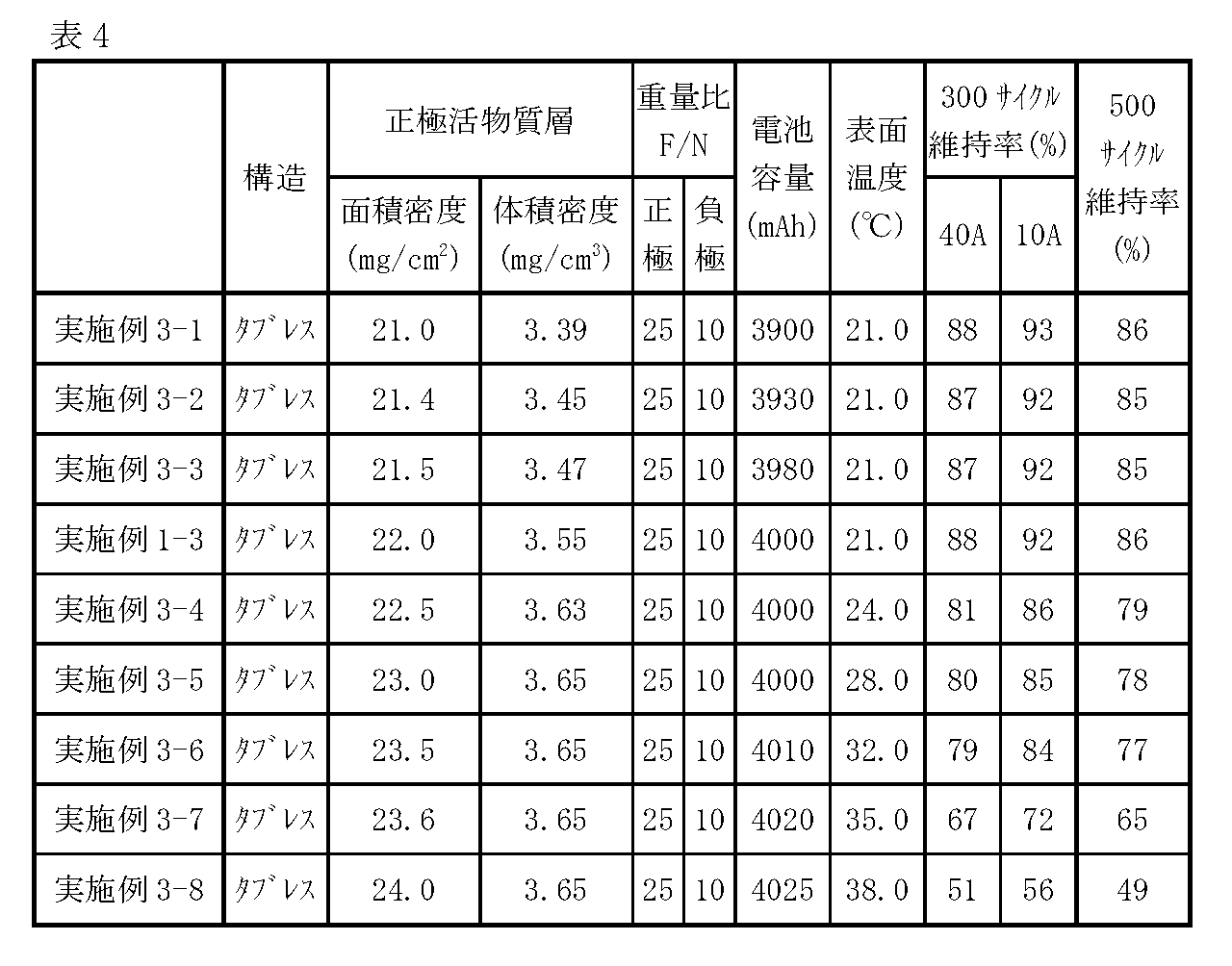
正極集電体21Aとしてのアルミニウム箔の厚さをそれぞれ表5に示した数値のものを用いたことを除き、他は実施例1-3と同様にして実施例4-1~4-5のリチウムイオン二次電池をそれぞれ作製し、実施例3-1~3-8と同様の電池特性の評価を実施した。その結果を表5に示す。
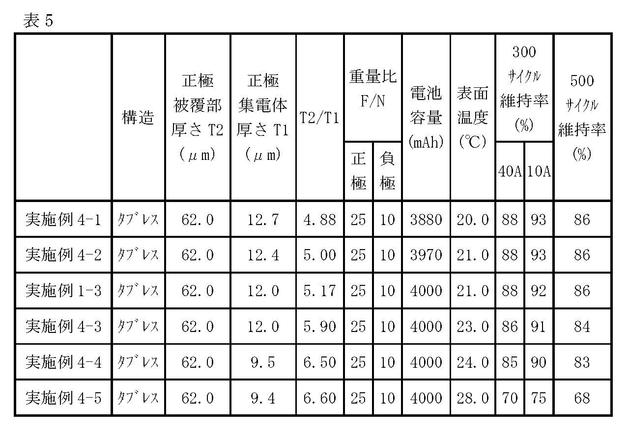
正極被覆部211の厚さT2がそれぞれ表6に示した数値となるように、かつ、正極活物質層21Bの体積密度がそれぞれ表6に示した数値となるように正極活物質層21Bの厚さを調整したことを除き、他は実施例1-3と同様にして実施例5-1~5-5のリチウムイオン二次電池をそれぞれ作製し、実施例3-1~3-8と同様の電池特性の評価を実施した。その結果を表6に示す。
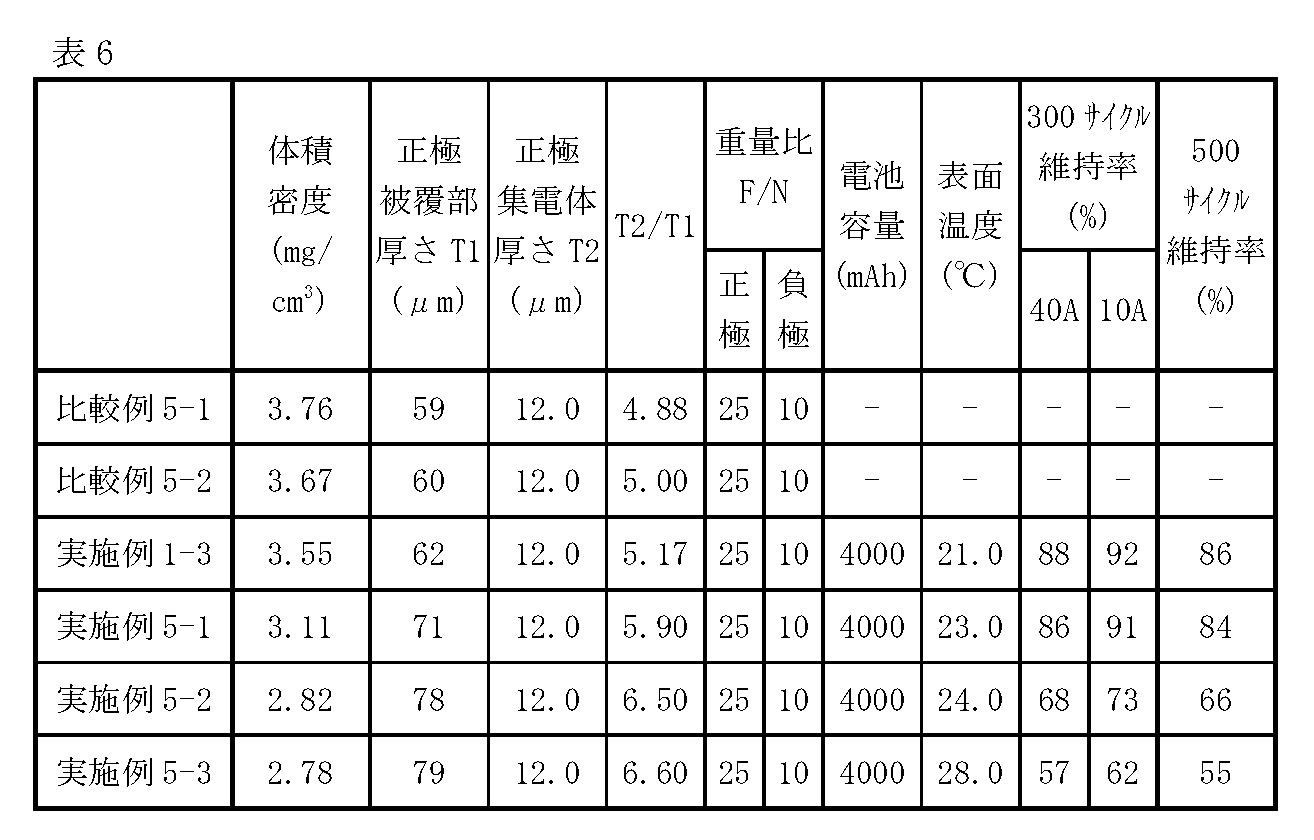
電解質塩の濃度がそれぞれ表7に示した数値となるように電解液を調整した。また、電解液(EC,DMC,およびFEC)中のLiBF4の濃度を0.004重量%とした。それらの点を除き、他は実施例1-3と同様にして実施例6-1~6-4,比較例6-1~6-4のリチウムイオン二次電池をそれぞれ作製し、電池特性の評価を実施した。ここでは、実施例3-1~3-8と同様に、電池容量、表面温度、および500サイクル維持率について評価した。その結果を表7に示す。

電解液(EC,DMC,およびFEC)中の電解質塩としてのLiBF4の濃度がそれぞれ表8に示した数値となるようにLiBF4の添加量を調整した。その点を除き、他は実施例1-3と同様にして実施例7-1~7-7のリチウムイオン二次電池をそれぞれ作製し、実施例3-1~3-8と同様に、電池容量、表面温度、および500サイクル維持率について評価した。その結果を表7に示す。

表1~表3に示したように、実施例1-1~1-4,2-1~2-17では、比較例1-1,1-2,2-1~2-4と比較して、優れたサイクル特性が得られることが確認できた。具体的には、表1に示したように、実施例1-1~1-4と比較例1-1,1-2との比較から、電解液における電解質塩の濃度が1.25mol/kg以上1.45mol/kg以下であると、優れたサイクル特性が得られることが確認できた。この結果は、本開示のリチウムイオン二次電池では、タブレス構造を採用して内部抵抗の低減を図りつつ電解質塩の濃度を適正化することにより、高負荷レート充電時の電池温度上昇を緩和し、電解質塩の分解反応を抑制できたことによるものと考えられる。
Claims (19)
- 正極と負極とがセパレータを介して積層されて第1の方向に延びる中心軸を中心に巻回されてなる電極巻回体と、
前記電極巻回体のうちの、前記第1の方向における第1端面と対向するように配置された正極集電板と、
前記電極巻回体のうちの、前記第1の方向における前記第1端面と反対側の第2端面と対向するように配置された負極集電板と、
電解液と、
前記電極巻回体、前記正極集電板、前記負極集電板、および前記電解液を収容する電池缶と
を備え、
前記正極は、正極集電体に正極活物質層が被覆されている正極被覆部と、前記正極集電体が前記正極活物質層に覆われずに露出し前記正極集電板と接合された正極露出部とを有し、
前記負極は、負極集電体に負極活物質層が被覆されている負極被覆部と、前記負極集電体が前記負極活物質層に覆われずに露出し前記負極集電板と接合された負極露出部とを有し、
前記中心軸を中心に巻回された前記正極露出部のうちの前記電極巻回体の径方向に隣り合う複数の第1縁部および前記中心軸を中心に巻回された前記負極露出部のうちの前記径方向に隣り合う複数の第2縁部、の少なくとも一方が互いに重なり合うように前記中心軸に向かって折れ曲がっており、
前記電解液は、電解質塩としてLiPF6を含有し、
前記電解液における前記電解質塩の濃度が1.25mol/kg以上1.45mol/kg以下である
二次電池。 - 前記電解質塩としてLiPF6に加えてLiBF4をさらに含み、
前記電解液におけるLiBF4の濃度は0.001(重量%)以上0.1(重量%)以下である
請求項1記載の二次電池。 - 前記正極活物質層の面積密度が21.5mg/cm2以上23.5mg/cm2以下である
請求項1または請求項2に記載の二次電池。 - 前記正極集電体の厚さに対する前記正極被覆部の厚さの比が5.0以上6.5以下である
請求項1から請求項3のいずれか1項に記載の二次電池。 - 前記正極活物質層の表層には、フッ素化合物および窒素化合物を含む正極被膜が形成されており、
前記負極活物質層の表層には、フッ素化合物および窒素化合物を含む負極被膜が形成されている
請求項1から請求項4のいずれか1項に記載の二次電池。 - 前記正極被膜における窒素含有量に対するフッ素含有量の重量比が3以上50以下であり、
前記負極被膜における窒素含有量に対するフッ素含有量の重量比が1以上30以下である
請求項5記載の二次電池。 - 前記正極被膜における窒素含有量に対するフッ素含有量の重量比および前記負極被膜における窒素含有量に対するフッ素含有量の重量比は、X線光電子分光分析法により測定される窒素原子の1s軌道のスペクトルピーク面積およびフッ素原子の1s軌道のスペクトルピーク面積に基づいて算出される
請求項6記載の二次電池。 - 前記正極活物質層における窒素含有量に対するフッ素含有量の重量比が15以上35以下であり、
前記負極活物質層における窒素含有量に対するフッ素含有量の重量比が5以上15以下である
請求項6または請求項7記載の二次電池。 - 前記電解液は、フッ素化合物およびニトリル化合物を含有する
請求項1から請求項8のいずれか1項に記載の二次電池。 - 前記フッ素化合物は、フッ素化エチレンカーボネート、トリフルオロカーボネート、トリフルオロエチルメチルカーボネート、フッ素化カルボン酸エステル、およびフッ素エーテルのうちの少なくとも1種を含む
請求項9記載の二次電池。 - 前記ニトリル化合物は、モノニトリル化合物、ジニトリル化合物、および3トリル化合物のうちの少なくとも1種を含む
請求項9または請求項10記載の二次電池。 - 前記ニトリル化合物はスクシノニトリルである
請求項9から請求項11のいずれか1項に記載の二次電池。 - 前記負極活物質層は、珪素、珪素酸化物、炭素珪素化合物、および珪素合金のうちの少なくとも1つを含有する負極活物質を含む
請求項1から請求項12のいずれか1項に記載の二次電池。 - 前記正極活物質層は、コバルト酸リチウム、リチウムニッケルコバルトマンガン酸化物、およびリチウムニッケルコバルトアルミニウム酸化物のうちの少なくとも1種を含有する正極活物質を含む
請求項1から請求項13のいずれか1項に記載の二次電池。 - 請求項1から請求項14のいずれか1項に記載の二次電池と、
前記二次電池を制御する制御部と、
前記二次電池を内包する外装体と
を有する電池パック。 - 請求項1から請求項14のいずれか1項に記載の二次電池と、
前記二次電池から供給された電力を駆動力に変換する変換部と、
前記駆動力に応じて駆動する駆動部と、
前記二次電池の動作を制御する制御部と
を備えた電動車両。 - 請求項15に記載の電池パックと、
複数の回転翼と、
前記回転翼をそれぞれ回転させるモータと、
前記回転翼及びモータをそれぞれ支持する支持軸と、
前記モータの回転を制御するモータ制御部と、
前記モータに電力を供給する電力供給ラインとを備え、
前記電池パックが前記電力供給ラインに接続されている
電動式航空機。 - 請求項1から請求項14のいずれか1項に記載の二次電池と、
前記二次電池から電力を供給される可動部と
を備えた電動工具。 - 請求項1から請求項14のいずれか1項に記載の二次電池を電力供給源として備えた電子機器。
Priority Applications (3)
| Application Number | Priority Date | Filing Date | Title |
|---|---|---|---|
| CN202280076523.7A CN118266117A (zh) | 2021-11-18 | 2022-11-16 | 二次电池、电池包、电子设备、电动工具、电动航空器以及电动车辆 |
| DE112022005496.4T DE112022005496T5 (de) | 2021-11-18 | 2022-11-16 | Sekundärbatterie, batteriepack, elektronisches gerät, elektrisches werkzeug, elektrisches luftfahrzeug und elektrisches fahrzeug |
| US18/647,651 US20240270395A1 (en) | 2021-11-18 | 2024-04-26 | Secondary battery, battery pack, electronic equipment, electric tool, electric aircraft, and electric vehicle |
Applications Claiming Priority (2)
| Application Number | Priority Date | Filing Date | Title |
|---|---|---|---|
| JP2021-187683 | 2021-11-18 | ||
| JP2021187683 | 2021-11-18 |
Related Child Applications (1)
| Application Number | Title | Priority Date | Filing Date |
|---|---|---|---|
| US18/647,651 Continuation US20240270395A1 (en) | 2021-11-18 | 2024-04-26 | Secondary battery, battery pack, electronic equipment, electric tool, electric aircraft, and electric vehicle |
Publications (1)
| Publication Number | Publication Date |
|---|---|
| WO2023090367A1 true WO2023090367A1 (ja) | 2023-05-25 |
Family
ID=86397141
Family Applications (1)
| Application Number | Title | Priority Date | Filing Date |
|---|---|---|---|
| PCT/JP2022/042586 Ceased WO2023090367A1 (ja) | 2021-11-18 | 2022-11-16 | 二次電池、電池パック、電子機器、電動工具、電動式航空機、および電動車両 |
Country Status (4)
| Country | Link |
|---|---|
| US (1) | US20240270395A1 (ja) |
| CN (1) | CN118266117A (ja) |
| DE (1) | DE112022005496T5 (ja) |
| WO (1) | WO2023090367A1 (ja) |
Citations (6)
| Publication number | Priority date | Publication date | Assignee | Title |
|---|---|---|---|---|
| JP2005056841A (ja) * | 2003-07-31 | 2005-03-03 | Samsung Sdi Co Ltd | 非水性電解質及びこれを含むリチウム二次電池 |
| JP2008210767A (ja) * | 2007-02-26 | 2008-09-11 | Samsung Sdi Co Ltd | リチウム二次電池 |
| JP2010015968A (ja) * | 2008-07-07 | 2010-01-21 | Samsung Sdi Co Ltd | リチウム二次電池 |
| WO2021020237A1 (ja) * | 2019-07-30 | 2021-02-04 | 株式会社村田製作所 | 二次電池、電池パック、電子機器、電動工具、電動式航空機及び電動車両 |
| JP2021028957A (ja) * | 2019-08-09 | 2021-02-25 | 株式会社豊田中央研究所 | 蓄電デバイス及び電極 |
| WO2021044968A1 (ja) * | 2019-09-05 | 2021-03-11 | 昭和電工株式会社 | 電極バインダー用共重合体及びリチウムイオン二次電池 |
-
2022
- 2022-11-16 CN CN202280076523.7A patent/CN118266117A/zh active Pending
- 2022-11-16 WO PCT/JP2022/042586 patent/WO2023090367A1/ja not_active Ceased
- 2022-11-16 DE DE112022005496.4T patent/DE112022005496T5/de active Pending
-
2024
- 2024-04-26 US US18/647,651 patent/US20240270395A1/en active Pending
Patent Citations (6)
| Publication number | Priority date | Publication date | Assignee | Title |
|---|---|---|---|---|
| JP2005056841A (ja) * | 2003-07-31 | 2005-03-03 | Samsung Sdi Co Ltd | 非水性電解質及びこれを含むリチウム二次電池 |
| JP2008210767A (ja) * | 2007-02-26 | 2008-09-11 | Samsung Sdi Co Ltd | リチウム二次電池 |
| JP2010015968A (ja) * | 2008-07-07 | 2010-01-21 | Samsung Sdi Co Ltd | リチウム二次電池 |
| WO2021020237A1 (ja) * | 2019-07-30 | 2021-02-04 | 株式会社村田製作所 | 二次電池、電池パック、電子機器、電動工具、電動式航空機及び電動車両 |
| JP2021028957A (ja) * | 2019-08-09 | 2021-02-25 | 株式会社豊田中央研究所 | 蓄電デバイス及び電極 |
| WO2021044968A1 (ja) * | 2019-09-05 | 2021-03-11 | 昭和電工株式会社 | 電極バインダー用共重合体及びリチウムイオン二次電池 |
Also Published As
| Publication number | Publication date |
|---|---|
| CN118266117A (zh) | 2024-06-28 |
| US20240270395A1 (en) | 2024-08-15 |
| DE112022005496T5 (de) | 2024-09-05 |
Similar Documents
| Publication | Publication Date | Title |
|---|---|---|
| JP7287467B2 (ja) | 二次電池、電池パック、電子機器、電動工具、電動式航空機及び電動車両 | |
| JP7355109B2 (ja) | 二次電池、電池パック、電子機器、電動工具、電動式航空機及び電動車両 | |
| JP7298691B2 (ja) | 二次電池、電池パック、電子機器、電動工具、電動式航空機及び電動車両 | |
| JP7315005B2 (ja) | 二次電池、電池パック、電動工具、電動式航空機及び電動車両 | |
| CN110710015B (zh) | 二次电池、电池包、电动车辆、电力储存系统、电动工具及电子设备 | |
| JP7151903B2 (ja) | 二次電池、電池パック、電子機器、電動工具、電動式航空機及び電動車両 | |
| KR20140055996A (ko) | 전지, 전극, 전지 팩, 전자 기기, 전동 차량, 축전 장치, 및 전력 시스템 | |
| CN110720149B (zh) | 二次电池、电池包、电动车辆、电力储存系统、电动工具以及电子设备 | |
| CN114080709A (zh) | 二次电池、电池包、电子设备、电动工具、电动式航空器以及电动车辆 | |
| CN114175390A (zh) | 二次电池、电池包、电子设备、电动工具、电动航空器以及电动车辆 | |
| JP2020053407A (ja) | 二次電池用負極、二次電池、電池パック、電動車両、電力貯蔵システム、電動工具および電子機器 | |
| CN114207906A (zh) | 二次电池、电池组、电子设备、电动工具、电动式航空器以及电动车辆 | |
| US20240282964A1 (en) | Secondary battery, battery pack, electronic equipment, electric tool, electric aircraft, and electric vehicle | |
| US20240405290A1 (en) | Secondary battery, battery pack, electronic equipment, electric tool, electric aircraft, and electric vehicle | |
| CN114041214A (zh) | 二次电池、电池包、电子设备、电动工具、电动航空器及电动车辆 | |
| US20240372128A1 (en) | Secondary battery, battery pack, electronic equipment,electric tool, electric aircraft, and electric vehicle | |
| US20240274889A1 (en) | Secondary battery, battery pack, electronic equipment, electric tool, electric aircraft, and electric vehicle | |
| JP7694803B2 (ja) | 二次電池、電池パック、電子機器、電動工具、電動式航空機、および電動車両 | |
| JPWO2018142682A1 (ja) | 二次電池用負極、二次電池、電池パック、電動車両、電力貯蔵システム、電動工具および電子機器 | |
| US20240270395A1 (en) | Secondary battery, battery pack, electronic equipment, electric tool, electric aircraft, and electric vehicle | |
| WO2023189636A1 (ja) | 二次電池、電池パック、電子機器、電動工具、電動式航空機、および電動車両、ならびに二次電池用電極巻回体の製造方法 |
Legal Events
| Date | Code | Title | Description |
|---|---|---|---|
| 121 | Ep: the epo has been informed by wipo that ep was designated in this application |
Ref document number: 22895648 Country of ref document: EP Kind code of ref document: A1 |
|
| WWE | Wipo information: entry into national phase |
Ref document number: 202280076523.7 Country of ref document: CN |
|
| WWE | Wipo information: entry into national phase |
Ref document number: 112022005496 Country of ref document: DE |
|
| 122 | Ep: pct application non-entry in european phase |
Ref document number: 22895648 Country of ref document: EP Kind code of ref document: A1 |
|
| NENP | Non-entry into the national phase |
Ref country code: JP |