WO2023089800A1 - 香味吸引器および香味吸引システム - Google Patents
香味吸引器および香味吸引システム Download PDFInfo
- Publication number
- WO2023089800A1 WO2023089800A1 PCT/JP2021/042720 JP2021042720W WO2023089800A1 WO 2023089800 A1 WO2023089800 A1 WO 2023089800A1 JP 2021042720 W JP2021042720 W JP 2021042720W WO 2023089800 A1 WO2023089800 A1 WO 2023089800A1
- Authority
- WO
- WIPO (PCT)
- Prior art keywords
- flavor
- consumable material
- heater
- heating
- housing
- Prior art date
- Legal status (The legal status is an assumption and is not a legal conclusion. Google has not performed a legal analysis and makes no representation as to the accuracy of the status listed.)
- Ceased
Links
Images


Classifications
-
- A—HUMAN NECESSITIES
- A24—TOBACCO; CIGARS; CIGARETTES; SIMULATED SMOKING DEVICES; SMOKERS' REQUISITES
- A24F—SMOKERS' REQUISITES; MATCH BOXES; SIMULATED SMOKING DEVICES
- A24F40/00—Electrically operated smoking devices; Component parts thereof; Manufacture thereof; Maintenance or testing thereof; Charging means specially adapted therefor
- A24F40/40—Constructional details, e.g. connection of cartridges and battery parts
- A24F40/46—Shape or structure of electric heating means
-
- A—HUMAN NECESSITIES
- A24—TOBACCO; CIGARS; CIGARETTES; SIMULATED SMOKING DEVICES; SMOKERS' REQUISITES
- A24D—CIGARS; CIGARETTES; TOBACCO SMOKE FILTERS; MOUTHPIECES OF CIGARS OR CIGARETTES; MANUFACTURE OF TOBACCO SMOKE FILTERS OR MOUTHPIECES
- A24D1/00—Cigars; Cigarettes
- A24D1/20—Cigarettes specially adapted for simulated smoking devices
-
- A—HUMAN NECESSITIES
- A24—TOBACCO; CIGARS; CIGARETTES; SIMULATED SMOKING DEVICES; SMOKERS' REQUISITES
- A24F—SMOKERS' REQUISITES; MATCH BOXES; SIMULATED SMOKING DEVICES
- A24F40/00—Electrically operated smoking devices; Component parts thereof; Manufacture thereof; Maintenance or testing thereof; Charging means specially adapted therefor
- A24F40/40—Constructional details, e.g. connection of cartridges and battery parts
-
- A—HUMAN NECESSITIES
- A24—TOBACCO; CIGARS; CIGARETTES; SIMULATED SMOKING DEVICES; SMOKERS' REQUISITES
- A24F—SMOKERS' REQUISITES; MATCH BOXES; SIMULATED SMOKING DEVICES
- A24F40/00—Electrically operated smoking devices; Component parts thereof; Manufacture thereof; Maintenance or testing thereof; Charging means specially adapted therefor
- A24F40/20—Devices using solid inhalable precursors
Definitions
- the present invention relates to a flavor suction device and a flavor suction system.
- flavor inhalers for inhaling flavors without burning materials have been known.
- a flavor inhaler for example, one having projections for sandwiching and compressing an inserted consumable is known (see, for example, Patent Document 1).
- One of the objects of the present invention is to provide a flavor suction device and flavor suction system that can be smoothly inserted while urging the consumable to the heater.
- a first aspect of the present invention provides a flavor inhaler.
- This flavor inhaler comprises a container for containing at least part of the consumable material, a heating unit inserted into the consumable material contained in the container to heat the consumable material from the inside, and a heating unit provided on the inner peripheral surface of the container. an urging part for urging the consumable item inserted into the container toward the heating part.
- the urging section urges the consumable material inserted into the storage section toward the heating section. Therefore, the consumable material can be brought into close contact with the heating section, and the efficiency of heat transfer from the heating section to the consumable material can be improved.
- At least one urging portion is provided at positions facing each other.
- At least one urging portion is provided at positions facing each other, thereby urging the consumables inserted into the storage portion toward the heating portion from directions facing each other. be able to.
- the length between the biasing portions facing each other is smaller than the diameter of the consumable before being inserted into the receiving portion.
- the length between the urging portions opposed to each other is made smaller than the diameter of the consumable material before it is inserted into the storage section, so that the consumable material is brought into close contact with the heating section. It is possible to further improve the efficiency of heat transfer from the heating unit to the consumable.
- the urging portions are alternately arranged in the longitudinal direction of the accommodating portion.
- the fourth aspect of the present invention by arranging the urging portions in a staggered manner in the longitudinal direction of the receiving portion, it is easier to insert the consumable material than when the urging portions are arranged at positions facing each other. , the frictional force on the surface of the consumable material can be moderated.
- the biasing portion protrudes from the inner peripheral surface of the housing portion toward the heating portion, and the projection distance is from the opening side of the housing portion. It is configured to gradually become longer toward the side opposite to the opening.
- the protruding distance of the urging portion gradually increases from the opening side of the housing portion toward the side opposite to the opening, so that the consumable material can be gradually deformed, Smooth deformation can be realized.
- the heating portion has a circumferential length in a cross section orthogonal to the longitudinal direction of the accommodating portion that gradually increases from the opening side of the accommodating portion toward the opposite side of the opening.
- the biasing portion is configured such that the protruding distance is maximized at a position where the peripheral length of the heating portion in a cross section orthogonal to the longitudinal direction of the housing portion is maximized.
- the protruding distance of the urging portion is maximized at the position where the circumferential length of the heating portion in the cross section perpendicular to the longitudinal direction of the accommodating portion is maximized, so that the consumable material is transferred to the heating portion.
- the heat transfer efficiency from the heating unit to the consumable material can be further improved.
- the biasing portion is configured such that the end opposite to the opening of the accommodating portion has a retaining shape.
- the end portion of the urging portion on the side opposite to the opening of the accommodating portion has a retaining shape, so that even when a force acts in the direction of pulling out the consumable item, Also, since resistance is generated by the retaining shape, it is possible to prevent the consumable from falling off.
- the heating section has an elliptical cross section orthogonal to the longitudinal direction of the accommodating section.
- the heating section has an elliptical cross section
- the storage section occupied by the consumable material has a shorter distance in the transverse direction than the heating section having the same cross section and having a circular cross section. Become. Therefore, it is possible to reduce the thickness of the housing portion.
- the heating part is flat.
- the heating section is flat, the contact area between the heating section and the consumable material can be increased. Therefore, the efficiency of heat transfer from the heating unit to the consumable material can be improved.
- the urging portion is provided along the minor axis or thickness direction of the heating portion.
- the urging portion is provided along the minor axis or thickness direction of the heating portion, thereby deforming the consumable material inserted into the storage portion into a flat shape, thereby heating the consumable material. It can be brought into close contact with the part.
- the urging portion is located near the end of the heating portion opposite to the opening of the housing portion in the major axis or width direction of the heating portion. provided along the
- the tip portion of the consumable material can be reliably brought into close contact with the heating portion. It is possible to improve the efficiency of heat transfer from the heating unit to the consumable.
- the heating unit has a heating element that generates heat and at least two substrates sandwiching the heating element.
- the substrates can support the heating element.
- the heating element is a heating element and the substrate is a conductive plate
- the conductive plate can support the heating element and also serve as an electrode.
- the biasing portion is configured so as not to overlap the heating element in the longitudinal direction of the accommodating portion.
- the urging portion does not overlap the heat generating element in the longitudinal direction of the accommodating portion, thereby suppressing heat generated from the heating element from escaping to the accommodating portion via the urging portion. be able to.
- a fourteenth form of the present invention provides a flavor suction system.
- This flavor inhalation system comprises a consumable and a flavor inhaler of any of the first to thirteenth aspects.
- the urging section urges the consumable material inserted into the storage section toward the heating section. Therefore, it is possible to obtain a flavor inhaling system having a flavor inhaler capable of bringing the consumable material into close contact with the heating unit and improving the efficiency of heat transfer from the heating unit to the consumable material.
- the consumable item has an inserted portion into which a heating portion that heats the consumable item from the inside is inserted, and the inserted portion surrounds the inserted heating portion.
- the inserted portion surrounds the inserted heating portion.
- the inserted portion includes an annular sheet disposed so as to surround the inserted heating portion. can be easily deformed along the shape of the heating part.
- the radial length from the inner periphery to the outer periphery of the inserted portion in a cross section orthogonal to the longitudinal direction of the consumable is greater than the shortest distance between the heating portion and the urging portion. is also big.
- the radial length from the inner periphery to the outer periphery of the inserted portion in the cross section orthogonal to the longitudinal direction of the consumable is made larger than the shortest distance between the heating portion and the urging portion.
- the urging portion can reliably urge the consumable material toward the heating portion, and the efficiency of heat transfer from the heating portion to the consumable material can be further improved.
- FIG. 2 is a cross-sectional view showing the main part of the flavor inhaler according to one embodiment of the present invention in the thickness direction of the heater.
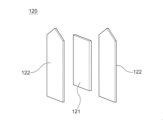
- 2 is an exploded perspective view of the heater shown in FIG. 1;
- FIG. FIG. 2 is a perspective view showing the heater shown in FIG. 1;
- 1 is a schematic cross-sectional side view of a consumable in accordance with one embodiment of the present invention;
- FIG. Fig. 6 is a cross-sectional view showing a cross section of the tobacco portion perpendicular to the longitudinal direction of the consumable product shown in Fig. 5;
- FIG. 4 is a cross-sectional view showing a state in which consumables are accommodated in a flavor inhaler;
- FIG. 4 is a cross-sectional view showing a state in which consumables are accommodated in a flavor inhaler;
- FIG. 4 is a cross-sectional view showing a state in which consumables are accommodated in a flavor inhaler;
- Fig. 10 is another cross-sectional view showing a state in which consumables are accommodated in the flavor inhaler;
- FIG. 5 is a cross-sectional view showing the arrangement of restraining ribs in the width direction of the heater;
- FIG. 5 is a cross-sectional view showing the arrangement of restraining ribs in the width direction of the heater;
- FIG. 4 is a cross-sectional view showing the arrangement of restraining ribs in the thickness direction of the heater;
- tobacco sticks are taken as an example of the consumable material, but the consumable material is not limited to tobacco as long as it generates flavor when heated.
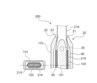
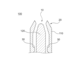
- FIG. 1 is a cross-sectional view showing the main part of the flavor inhaler 100 according to one embodiment of the present invention in the width direction of the heater 120.
- FIG. FIG. 2 is a cross-sectional view showing the main part of the flavor inhaler 100 according to one embodiment of the present invention in the thickness direction of the heater 120. As shown in FIG.
- the flavor inhaler 100 includes a housing (accommodating section) 110 and a heater (heating section) 120 .
- the housing 110 has an opening 10 at one end and accommodates at least a portion of a consumable item 200 (described below) inserted into the opening 10 through the opening 10 .
- the housing 110 is made of, for example, a resin, particularly PC (Polycarbonate), ABS (Acrylonitrile-Butadiene-Styrene) resin, PEEK (PolyEtherEtherKetone), a polymer alloy containing a plurality of types of polymers, or aluminum. It can be made of metal.
- the housing 110 is configured such that the cross-sectional area in the cross section perpendicular to the longitudinal direction of the housing 110 is the smallest in the vicinity of the opening 10 .
- the housing 110 has a shaping guide (guide portion) 20 and a restraining rib (biasing portion) 30 .
- the shaping guide 20 forms the opening 10 and deforms the cross-sectional shape of the consumable 200 inserted into the housing 110 so as to correspond to the shape of the heater 120 .
- the restraining ribs 30 are provided on the inner peripheral surface of the housing 110 and urge the consumable material 200 inserted into the housing 110 toward the heater 120 to deform the shape of the consumable material 200 .
- the detailed configuration of the shaping guides 20 and the restraining ribs 30 and the function of deforming the consumable material 200 will be described later.
- an air intake hole (not shown) is provided on the side opposite to the opening 10 of the housing 110.
- a bottom-flow type flavor inhaler 100 is configured by supplying air to the consumable material 200 inserted into the housing 110 through the air intake hole.
- the intake hole may be provided in a member forming the bottom of the housing 110 and communicate with the consumable product 200 through the inside of the member.
- the heater 120 is a flat PTC (Positive Temperature Coefficient) heater that is inserted into the consumable material 200 housed in the housing 110 and heats the consumable material 200 from the inside. Also, the heater 120 deforms the outer shape of the consumable material 200 inserted into the housing 110 along the shape of the heater 120 . The function of the heater 120 to deform the consumable material 200 will be described later.
- the shaping guide 20, the restraining ribs 30, and the heater 120 deform the shape of the consumable material 200 after being housed in the housing 110 from the shape of the consumable material 200 before being housed in the housing 110. be.
- FIG. 3 is an exploded perspective view of the heater shown in FIG. 4 is a perspective view showing the heater shown in FIG. 1.
- the heater 120 has a PTC element (heating element) 121, at least two metal plates (substrates) 122, and a holding member 123.
- the PTC element 121 is sandwiched from both sides by metal plates 122 and adhered with, for example, a conductive adhesive paste.
- a conductive adhesive paste for example, a so-called anisotropic conductive adhesive in which conductive particles are uniformly dispersed in an epoxy adhesive can be used.
- the metal plate 122 may be made of a nickel (Ni)-containing iron alloy with a low coefficient of thermal expansion, such as Invar (registered trademark). According to this, the metal plate 122 can suppress peeling of the adhesion between the metal plate 122 and the PTC element 121 due to thermal expansion when the PTC element 121 generates heat. By sandwiching the PTC element 121 between at least two metal plates 122, the metal plates 122 can support the PTC element 121 and also serve as electrodes.
- Ni nickel
- Invar registered trademark
- the holding member 123 is coupled to the housing 110 when the heater 120 is attached to the housing 110 .
- the holding portion 123 may be made of engineering plastic.
- Engineering plastics have high heat resistance and high mechanical strength, and can be formed into desired shapes at low cost by injection molding or the like, and are thus suitably used as constituent materials for structural members.
- the holding portion 123 may be made of PEEK, which is a type of engineering plastic.
- PEEK is a thermoplastic resin that has extremely high heat resistance and high dimensional stability. Therefore, when the holding member 123 is made of PEEK, the holding member 123 can further reduce the influence of heat generated by the heater 120 .
- a PTC heater is a heater that uses a resistor that has a property (PTC property) that the electrical resistance rises sharply when reaching a certain temperature (called the Curie temperature), and electricity stops flowing.
- the PTC heater can keep the temperature below a certain temperature without using a control device or the like by utilizing the PTC characteristics.
- the heater 120 may be a PTC heater using barium titanate (BaTiO 3 ) having PTC characteristics as a resistor. In such a case, the heater 120 can set the Curie temperature of barium titanate to 350.degree.
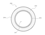
- FIG. 5 is a schematic side sectional view showing a consumable product 200 according to one embodiment of the invention.
- FIG. 6 is a cross-sectional view showing a section of the tobacco portion 210 perpendicular to the longitudinal direction of the consumable product 200 shown in FIG.
- the consumable product 200 has a tobacco portion (inserted portion) 210 and a paper tube 220 .
- the tobacco portion 210 has a through hole 211 in the center into which the heater 120 is inserted.
- the tobacco portion 210 has a two-layer structure of a flavor release layer (annular sheet) 212 and an elastically deformable layer (annular sheet) 213 arranged so as to surround the inserted heater 120 .
- a wrapper 214 is wound around the outer periphery of the elastic deformation layer 213 .
- the flavor-releasing layer 212 is composed of, for example, a tobacco sheet and a non-tobacco sheet carrying glycerin around the tobacco sheet, and is heated by the heater 120 to release flavor-containing volatile compounds. It should be noted that the flavor release layer 212 can include only one of tobacco sheets and non-tobacco sheets.
- the elastic deformation layer 213 is made of, for example, a non-woven fabric sheet, a corrugated sheet, a non-tobacco sheet, or the like, and is elastically deformable in its thickness direction (that is, the radial direction of the cylindrical elastic deformation layer 213). The elastic deformation layer 213 contributes to the deformation of the consumable material 200 along the shape of the heater 120 when the heater 120 is inserted.
- the elastic deformation layer 213 is elastically deformed in the thickness direction with respect to the heater 120 , making it easier to contact or approach the heater 120 . Therefore, the flavor release layer 212 can be brought into contact with or closer to the heater 120, and the consumable material 200 can be efficiently heated.
- the paper tube 220 cools the volatile compounds released from the flavor release layer 212.
- Tobacco portion 210 includes flavor release layer 212 and elastically deformable layer 213 arranged to surround heater 120 to be inserted, so that heater 120 is inserted into consumable material 200 to change the shape of consumable material 200. It can be easily transformed.
- the cross-sectional shape of the consumable material 200 may be circular or elliptical.
- the non-tobacco sheet may contain a flavor generating base material.
- the flavor-generating base material is a material that imparts flavor and taste, and is preferably a tobacco material.
- Flavor-generating substrates may also include perfumes.
- a flavoring agent is a substance that provides an odor or flavor.
- the perfume may be a natural perfume or a synthetic perfume.
- the perfume one kind of perfume may be used, or a mixture of multiple kinds of perfumes may be used.
- the fragrance for example, any fragrance such as essential oil, natural fragrance, synthetic fragrance, etc. can be used as long as it is a fragrance that is usually used.
- it may be liquid or solid, and its properties are not limited.
- the flavor generating substrate may also include cooling agents or flavorants.
- the tobacco sheet may contain, for example, tobacco, polyhydric alcohol, and the like.
- Polyhydric alcohols may be used alone or in combination of two or more in the tobacco sheet.
- the polyhydric alcohol may also be added to the elastic deformation layer 213 described above.
- Tobacco sheets can be formed into sheets by mixing powdered tobacco and polyhydric alcohol with a binder.
- Describe relationships. 7 to 9 are cross-sectional views showing a state in which the consumable material 200 is accommodated in the flavor inhaler 100.
- the consumable material 200 is applied to the flavor inhaler 100 to configure the flavor inhaling system.
- 7 to 9 show the flavor release layer 212 and the elastically deformable layer 213 of the consumable product 200 as one annular sheet 215.
- FIG. 7 shows a state in which the consumable material 200 passes through the shaping guide 20 with respect to a cross section in the width direction of the heater 120 and a cross section perpendicular to the longitudinal direction of the housing 110 at the entrance portion 22 of the shaping guide 20 .
- FIG. 8 shows a state in which the consumable material 200 passes through the restraining rib 30, in cross section in the width direction of the heater 120, and at the intermediate portion and the other end of the restraining rib 30, perpendicular to the longitudinal direction of the housing 110. It shows the cross section to be done.
- FIG. 8 shows a state in which the consumable material 200 passes through the restraining rib 30, in cross section in the width direction of the heater 120, and at the intermediate portion and the other end of the restraining rib 30, perpendicular to the longitudinal direction of the housing 110. It shows the cross section to be done.
- FIG. 9 shows a state in which the consumable material 200 is accommodated in a predetermined accommodation position of the housing 110, in a cross section in the width direction of the heater 120 and in the longitudinal direction of the housing 110 near the other end of the heater 120. An orthogonal cross section is shown.
- the shaping guide 20 has a tapered portion 21, an inlet portion 22, and a contact portion 23.
- the tapered portion 21 is configured to expand toward one end of the housing 110 and guides the insertion of the consumable material 200 into the flavor inhaler 100 . That is, the shaping guide 20 guides the consumable material 200 to the tip position of the heater 120 so that the consumable material 200 can be reliably inserted into the heater 120 .
- the shaping guide 20 has a tapered shape expanded toward the outside of the housing 110 to guide the insertion of the consumable material 200, so that the consumable material 200 can be easily accommodated in the housing 110. can do.
- the entrance part 22 is provided at the end of the housing 110 and has an elliptical cross-section, and has a long axis equal to or larger than the long axis of the consumable material 200 after being housed in the housing 110 and a short axis of being housed in the housing 110 . It is configured to be approximately the same length as the diameter of the consumable 200 prior to insertion.
- the end of the shaping guide 20 has an elliptical cross section, the cross-sectional shape of the consumable product 200 is deformed into an elliptical shape along the shape of the shaping guide 20 as the consumable product 200 is inserted. be able to.
- the short diameter of the inlet portion 22 is substantially the same as the diameter of the consumable product 200 before it is housed in the housing 110, it is possible to suppress wobbling of the consumable product 200 in the direction of the short diameter of the shaping guide 20. .
- the shaping guide 20 can shape the consumable material 200 into a constant shape, and the consumable material 200 can be smoothly attached to the housing 110 .
- the heater 120 and the entrance portion 22 are configured such that the width direction of the heater 120 coincides with the longitudinal direction of the entrance portion 22 . Thereby, the consumable material 200 inserted into the housing 110 can be deformed along the shape of the heater 120 . Therefore, the consumable material 200 can be brought into close contact with the heater 120, and the heat transfer efficiency from the heater 120 to the consumable material 200 can be improved.
- the contact part 23 is provided on the inner peripheral surface of the housing 110 and has an elliptical cross section, and is configured such that the minimum inner peripheral length is equal to or less than the outer peripheral length of the consumable product 200 .
- the cross-sectional shape of the consumable material 200 can be deformed into a desired shape by the shaping guide 20, and the consumable material 200 can be smoothly inserted into the housing 110.
- the consumable material 200 can be prevented from falling off.
- the contact portion 23 is configured to make point contact with the consumable material 200 housed in the housing 110 in a cross section along the longitudinal axis of the housing 110 .
- the point contact of the contact portion 23 with the consumable material 200 suppresses the heat transfer from the consumable material 200 to the housing 110 , so that the heat insulation performance of the flavor inhaler 100 can be improved.
- the heater 120 has a sharp tip shape. Therefore, the heater 120 can be easily inserted into the consumable item 200 .
- the end of the heater 120 on the side of the opening 10 protrudes toward the opening 10 more than the end of the shaping guide 20 on the side opposite to the opening 10 .
- the end of the heater 120 on the side of the opening 10 slightly protrudes toward one end of the housing 110 from the contact portion 23 in the longitudinal direction of the housing 110 .
- the end of the heater 120 on the opening 10 side is inserted into the through hole 211 of the consumable material 200, so that the deformation of the consumable material 200 by the heater 120 is reliably started. can do.
- the maximum width of the heater 120 with respect to the length of the contact portion 23 of the shaping guide 20 is configured to be larger than that of the conventional flavor inhaler having a piercing-type heater.
- the length of the contact portion 23 is 7 mm
- the maximum width of the heater 120 is 6 mm.
- the heater 120 is configured such that the maximum width of the heater 120 is greater than 30%, preferably greater than 40%, of the major axis of the consumable material 200 after being housed in the housing 110 .
- the consumable material 200 inserted into the housing 110 can be deformed into a flat shape, and the consumable material 200 can be brought into close contact with the heater 120 .
- the heater 120 has a sharp shape and is configured so that its width increases toward the other end. Accordingly, as the consumable product 200 is inserted through the shaping guide 20 , the contour of the consumable product 200 is deformed along the shape of the heater 120 . Specifically, the consumable material 200 is spread in the width direction of the heater 120 . As a result, the consumable material 200 can be brought into close contact with the heater 120, and the heat transfer efficiency from the heater 120 to the consumable material 200 can be improved. In addition, since the heater 120 spreads the consumable material 200, it is possible to prevent the consumable material 200 from falling off.
- the heater 120 has a flat plate shape, and deforms the outer shape of the consumable material 200 inserted into the housing 110 into an elliptical cross-sectional shape.
- the major axis of the consumable material 200 after being housed in the housing 110 is longer than the diameter of the consumable material 200 before being housed in the housing 110, and the diameter of the consumable material 200 after being housed in the housing 110.
- the short diameter is shorter than the diameter of the consumable item 200 before being housed in the housing 110 .
- the heater 120 deforms the outer shape of the consumable material 200 to be inserted into the housing 110 into an elliptical cross-sectional shape, thereby shortening the width of the housing 110 occupied by the consumable material 200 .
- the housing 110 can be made thinner. Further, the contact area between the heater 120 and the consumable item 200 can be increased by deforming the outer shape of the consumable item 200 inserted into the housing 110 into an elliptical cross-sectional shape. Therefore, heat transfer efficiency from the heater 120 to the consumable material 200 can be improved.
- the heater 120 is arranged so that the circumference of the cross section perpendicular to the longitudinal direction of the housing 110 gradually increases from the side of the opening 10 toward the side opposite to the side of the opening 10, that is, from one end toward the other end. is configured to As the circumferential length of the heater 120 gradually increases from one end to the other end, the contact length of the consumable material with the heating unit gradually increases from one end to the other end. It is possible to prevent the material from falling off.
- the restraining rib 30 is provided so as to protrude from the inner peripheral surface of the housing 110 toward the heater 120 along the thickness direction of the heater 120, and is composed of a pair of tapered surfaces facing each other (see FIG. 2). . It should be noted that the restraining ribs 30 are not limited to this configuration, and at least one restraining rib 30 may be provided at positions facing each other. In addition, the restraining rib 30 is arranged so as to overlap the region where the width of the heater 120 gradually widens in the longitudinal direction of the housing 110 . In addition, the shape of the restraining rib 30 can be selected from arbitrary projecting shapes.
- the restraining rib 30 is configured so that the projection distance gradually increases toward the other end side of the housing 110, and the position where the width of the heater 120 is maximized, that is, the longitudinal direction of the housing 110 is perpendicular to the position.
- the protruding distance may be maximized at the position where the circumferential length in the cross section is maximized.
- the length between the tapered surfaces of the restraining ribs 30 is configured to be smaller than the diameter of the consumable material 200 before being inserted into the housing 110 .
- the other end of the restraining rib 30 has a retaining shape formed in the shape of a precipitous wall that is substantially orthogonal to the inner peripheral surface of the housing 110 , and the restraining rib 30 extends along the longitudinal direction of the housing 110 . 30 is configured so as not to overlap the PTC element 121 of the heater 120 .
- the pressing rib 30 urges the consumable material 200 pushed and spread in the width direction of the heater 120 in the thickness direction of the heater 120. Deformed into a flat shape.
- the projection distance of the restraining rib 30 increases, and the consumable material 200 is gradually deformed into a flat shape.
- both the width of the heater 120 and the projecting distance of the restraining rib 30 are maximized, and the shape of the consumable material 200 is the final shape in close contact with the heater 120. It has a shape. Therefore, the consumable material 200 inserted into the housing 110 is urged toward the heater 120 by the restraining ribs 30 , so that the consumable material 200 can be brought into close contact with the heater 120 . heat transfer efficiency can be further improved. In addition, since the restraining rib 30 biases the consumable material 200, it is possible to prevent the consumable material 200 from falling off.
- the radial length from the inner circumference to the outer circumference of the tobacco portion 210 in the cross section perpendicular to the longitudinal direction of the consumable article 200 is the distance between the heater 120 and the restraining ribs 30. It may be configured to be greater than the shortest distance. According to this, the consumable material 200 can be reliably urged against the heater 120 by the restraining rib 30, and the heat transfer efficiency from the heater 120 to the consumable material 200 can be further improved.
- the consumable material 200 inserted into the housing 110 can be deformed into a flat shape, and the consumable material 200 can be brought into close contact with the heater 120. . Also, by providing at least one restraining rib 30 at positions facing each other, the consumables 200 inserted into the housing 110 can be urged toward the heater 120 from directions facing each other. Further, by setting the length between the tapered surfaces of the restraining ribs 30 to be smaller than the diameter of the consumable material 200, the consumable material 200 can be brought into close contact with the heater 120, and the heat transfer efficiency from the heater 120 to the consumable material 200 can be improved. can be further improved.
- the consumable material 200 can be gradually deformed, and smooth deformation can be realized. Further, by forming the other end portion of the restraining rib 30 into a retaining shape, even if a force acts in the direction of pulling out the consumable material 200, resistance is generated due to the retaining shape. can be prevented from falling off. Also, in the longitudinal direction of the housing 110 , the restraining ribs 30 do not overlap the PTC element 121 of the heater 120 , thereby preventing the heat generated from the PTC element 121 from escaping to the housing 110 through the restraining ribs 30 . can be suppressed.
- an accommodation space 50 is formed inside the housing 110 to accommodate the consumable material 200 deformed by the heater 120 .
- an air layer 40 is formed over the entire circumference of the consumable material 200 between the housing space 50 and the housing 110 . Since the air layer 40 has a low thermal conductivity, it can insulate between the consumable material 200 (accommodating space 50) and the housing 110, and the energy required for heating the consumable material 200 can be reduced. Further, the inlet portion 22 is in contact with the consumable material 200 over the entire circumference of the consumable material 200 and seals the air layer 40 . This suppresses air convection in the air layer 40 .
- the housing 110 is configured such that the cross-sectional area of the cross section perpendicular to the longitudinal direction of the housing 110 is the smallest in the vicinity of the opening 10 .
- the housing 110 is arranged so that the ratio of the cross-sectional areas of the air layer 40 and the consumable material 200 is from 5:1 to 1:1 at the point where the cross-sectional area in the cross section orthogonal to the longitudinal direction of the housing 110 is the largest. is configured to Thereby, the air layer 40 can exhibit sufficient heat insulation performance.
- the shaping guide 20 deforms the cross-sectional shape of the consumable material 200
- the heater 120 deforms the shape of the consumable material 200 along the shape of the heater 120
- the restraining ribs 30 direct the consumable material 200 toward the heater 120 .
- the shaping guide 20 deforms the cross-sectional shape of the consumable material 200 inserted into the housing 110 so as to correspond to the shape of the heater 120 . Therefore, even if the cross-sectional shape of the consumable material 200 inserted into the housing 110 varies, the shaping guide 20 can deform the cross-sectional shape of the consumable material 200 into a desired shape corresponding to the shape of the heater 120. .
- the outer shape of the consumable material 200 inserted into the housing 110 is deformed along the shape of the heater 120 by the heater 120 . Therefore, the consumable material 200 can be brought into close contact with the heater 120, and the heat transfer efficiency from the heater 120 to the consumable material 200 can be improved.
- the shape of the consumable material 200 after being housed in the housing 110 is changed from the shape of the consumable material 200 before being housed in the housing 110 by the shaping guide 20, the restraining rib 30, and the heater 120, Even if there is, an air layer 40 is formed between the accommodation space 50 in which the deformed consumable product 200 is accommodated and the housing 110 . Therefore, the heat insulation performance of the flavor inhaler 100 can be improved by the air layer 40 having a low thermal conductivity.
- the abutting part 23 forms an air layer 40 between the housing space 50 in which the deformed consumable material 200 is housed and the housing 110.
- air convection in the air layer 40 can be suppressed, and excellent heat insulation performance can be achieved.
- the contact portion 23 is provided near the opening 10, the volume of the sealed air layer 40 can be increased, so that the heat insulation performance of the flavor inhaler 100 can be improved.
- the heater 120 by inserting the heater 120 into the consumable material 200 and heating the consumable material 200 from the inside, the heater 120 as a heat source does not come into contact with the air layer 40, so that the heat insulation performance of the flavor inhaler 100 can be further improved. can.
- the air layer 40 is formed along the entire circumference of the consumable material 200, the heat insulation performance of the flavor inhaler 100 can be further improved.
- the heater 120 is a PTC heater
- the heater may be a flexible polyimide heater configured by sandwiching a heat generating resistor (heat generating element) such as stainless steel between two films (substrates) such as PI (polyimide).
- the heater may be a pin heater having an elliptical cross section perpendicular to the longitudinal direction of the housing 110 .
- the intake hole is provided on the side opposite to the opening 10 of the housing 110, that is, on the bottom of the housing 110.
- the present invention is not limited to this. may be provided in the opening 10 of the housing 110 or in the housing 110 .
- the air intake hole is provided in the housing 110, as shown in FIG. Even in this case, since the air layer 40 is sealed by the contact portion 23, it is possible to suppress the occurrence of convection in the air layer 40 in the vicinity of the contact portion 23, thereby preventing a decrease in heat insulating efficiency. Air can flow in while maintaining the size of the flavor inhaler 100 while preventing this.
- the pressing rib 30 is configured by a pair of tapered surfaces facing each other, but the present invention is not limited to this.
- 11 and 12 are cross-sectional views showing the arrangement of the restraining ribs 30 in the width direction of the heater 120.
- FIG. FIG. 13 is a cross-sectional view showing the arrangement of the restraining ribs 30 in the thickness direction of the heater 120. As shown in FIG.
- the restraining ribs 30 are alternately arranged in the longitudinal direction of the housing 110 .
- the frictional force applied to the surface of the consumable material 200 when the consumable material 200 is inserted is reduced as compared with the case where the restraining ribs 30 are arranged at positions facing each other. be able to.
- the restraining ribs 30 are arranged along the thickness direction of the heater 120 near the other end of the heater 120 so as to face each other.
- the restraining ribs 30 are arranged along the width direction of the heater 120 near the other end of the heater 120 so as to face each other.
Landscapes
- Resistance Heating (AREA)
- Thermotherapy And Cooling Therapy Devices (AREA)
- Packaging Of Annular Or Rod-Shaped Articles, Wearing Apparel, Cassettes, Or The Like (AREA)
Priority Applications (5)
| Application Number | Priority Date | Filing Date | Title |
|---|---|---|---|
| EP21964815.1A EP4437871A4 (en) | 2021-11-22 | 2021-11-22 | AROMA INHALER AND AROMA INHALATION SYSTEM |
| PCT/JP2021/042720 WO2023089800A1 (ja) | 2021-11-22 | 2021-11-22 | 香味吸引器および香味吸引システム |
| KR1020247011878A KR20240064687A (ko) | 2021-11-22 | 2021-11-22 | 향미 흡인기 및 향미 흡인 시스템 |
| JP2023562074A JP7735424B2 (ja) | 2021-11-22 | 2021-11-22 | 香味吸引器および香味吸引システム |
| US18/627,472 US20240245124A1 (en) | 2021-11-22 | 2024-04-05 | Flavor inhaler and flavor inhalation system |
Applications Claiming Priority (1)
| Application Number | Priority Date | Filing Date | Title |
|---|---|---|---|
| PCT/JP2021/042720 WO2023089800A1 (ja) | 2021-11-22 | 2021-11-22 | 香味吸引器および香味吸引システム |
Related Child Applications (1)
| Application Number | Title | Priority Date | Filing Date |
|---|---|---|---|
| US18/627,472 Continuation US20240245124A1 (en) | 2021-11-22 | 2024-04-05 | Flavor inhaler and flavor inhalation system |
Publications (1)
| Publication Number | Publication Date |
|---|---|
| WO2023089800A1 true WO2023089800A1 (ja) | 2023-05-25 |
Family
ID=86396570
Family Applications (1)
| Application Number | Title | Priority Date | Filing Date |
|---|---|---|---|
| PCT/JP2021/042720 Ceased WO2023089800A1 (ja) | 2021-11-22 | 2021-11-22 | 香味吸引器および香味吸引システム |
Country Status (5)
| Country | Link |
|---|---|
| US (1) | US20240245124A1 (https=) |
| EP (1) | EP4437871A4 (https=) |
| JP (1) | JP7735424B2 (https=) |
| KR (1) | KR20240064687A (https=) |
| WO (1) | WO2023089800A1 (https=) |
Citations (6)
| Publication number | Priority date | Publication date | Assignee | Title |
|---|---|---|---|---|
| WO2018235956A1 (ja) * | 2017-06-22 | 2018-12-27 | 日本たばこ産業株式会社 | 香味発生セグメント、ならびにこれを備える香味発生物品および香味吸引システム |
| JP2019165751A (ja) | 2015-08-31 | 2019-10-03 | ブリティッシュ アメリカン タバコ (インヴェストメンツ) リミテッドBritish American Tobacco (Investments) Limited | 喫煙材を加熱するための装置 |
| WO2019224310A1 (en) * | 2018-05-25 | 2019-11-28 | Jt International Sa | Vapour generating device with sensors to measure strain generated by a vapour generating material |
| JP2020517073A (ja) * | 2017-05-30 | 2020-06-11 | ヘレウス ネクセンソス ゲーエムベーハーHeraeus Nexensos GmbH | 共焼結された多層構造を有するヒータ |
| WO2020127107A1 (en) * | 2018-12-17 | 2020-06-25 | Philip Morris Products S.A. | Tubular element, comprising porous medium, for use with an aerosol generating article |
| WO2020213137A1 (ja) * | 2019-04-18 | 2020-10-22 | 日本たばこ産業株式会社 | 加熱式たばこ |
Family Cites Families (6)
| Publication number | Priority date | Publication date | Assignee | Title |
|---|---|---|---|---|
| ES2589260T5 (es) * | 2011-11-21 | 2022-07-15 | Philip Morris Products Sa | Extractor para un dispositivo generador de aerosol |
| CN111713750B (zh) * | 2016-12-16 | 2023-09-05 | 韩国烟草人参公社 | 气溶胶生成系统 |
| CN110494053B (zh) * | 2017-04-11 | 2022-05-31 | 韩国烟草人参公社 | 气溶胶生成装置 |
| CN108451028B (zh) * | 2018-01-22 | 2024-10-15 | 上海新型烟草制品研究院有限公司 | 松脱机构、气雾产生装置、松脱方法及发烟制品 |
| CN209807157U (zh) * | 2019-04-12 | 2019-12-20 | 湖南中烟工业有限责任公司 | Ptc发热体及低温烟具 |
| JP7547370B2 (ja) * | 2019-04-29 | 2024-09-09 | フィリップ・モーリス・プロダクツ・ソシエテ・アノニム | 加熱ゾーン絶縁部を備えたエアロゾル発生装置 |
-
2021
- 2021-11-22 WO PCT/JP2021/042720 patent/WO2023089800A1/ja not_active Ceased
- 2021-11-22 JP JP2023562074A patent/JP7735424B2/ja active Active
- 2021-11-22 EP EP21964815.1A patent/EP4437871A4/en active Pending
- 2021-11-22 KR KR1020247011878A patent/KR20240064687A/ko active Pending
-
2024
- 2024-04-05 US US18/627,472 patent/US20240245124A1/en active Pending
Patent Citations (6)
| Publication number | Priority date | Publication date | Assignee | Title |
|---|---|---|---|---|
| JP2019165751A (ja) | 2015-08-31 | 2019-10-03 | ブリティッシュ アメリカン タバコ (インヴェストメンツ) リミテッドBritish American Tobacco (Investments) Limited | 喫煙材を加熱するための装置 |
| JP2020517073A (ja) * | 2017-05-30 | 2020-06-11 | ヘレウス ネクセンソス ゲーエムベーハーHeraeus Nexensos GmbH | 共焼結された多層構造を有するヒータ |
| WO2018235956A1 (ja) * | 2017-06-22 | 2018-12-27 | 日本たばこ産業株式会社 | 香味発生セグメント、ならびにこれを備える香味発生物品および香味吸引システム |
| WO2019224310A1 (en) * | 2018-05-25 | 2019-11-28 | Jt International Sa | Vapour generating device with sensors to measure strain generated by a vapour generating material |
| WO2020127107A1 (en) * | 2018-12-17 | 2020-06-25 | Philip Morris Products S.A. | Tubular element, comprising porous medium, for use with an aerosol generating article |
| WO2020213137A1 (ja) * | 2019-04-18 | 2020-10-22 | 日本たばこ産業株式会社 | 加熱式たばこ |
Non-Patent Citations (1)
| Title |
|---|
| See also references of EP4437871A4 |
Also Published As
| Publication number | Publication date |
|---|---|
| EP4437871A4 (en) | 2025-09-17 |
| EP4437871A1 (en) | 2024-10-02 |
| JP7735424B2 (ja) | 2025-09-08 |
| KR20240064687A (ko) | 2024-05-13 |
| JPWO2023089800A1 (https=) | 2023-05-25 |
| US20240245124A1 (en) | 2024-07-25 |
Similar Documents
| Publication | Publication Date | Title |
|---|---|---|
| US20230413902A1 (en) | E-vapor device including puncture device and sealed packet of pre-vapor formulation | |
| CN111759010B (zh) | 一种具有气液通道的气雾弹 | |
| KR102827785B1 (ko) | 전자 에어로졸 제공 시스템 | |
| RU2742806C1 (ru) | Системы предоставления пара | |
| KR20200094137A (ko) | 내부 표면 서셉터 재료를 갖는 카트리지 | |
| CN108601398A (zh) | 气溶胶生成系统和用于这类系统的气溶胶生成制品 | |
| CN112512353A (zh) | 电子烟以及用于电子烟的囊体 | |
| TW202038752A (zh) | 具有可壓縮芯吸件之電子煙煙彈 | |
| KR20200123245A (ko) | 증기 제공 시스템들 | |
| US20210282461A1 (en) | Device for generating an aerosol | |
| WO2023089801A1 (ja) | 香味吸引器および香味吸引システム | |
| WO2023089800A1 (ja) | 香味吸引器および香味吸引システム | |
| JP7723113B2 (ja) | 香味吸引器、香味吸引システムおよび消費材の変形方法 | |
| WO2023089798A1 (ja) | 香味吸引器および香味吸引システム | |
| WO2023089802A1 (ja) | 香味吸引器および香味吸引システム | |
| US20240284979A1 (en) | Flavor inhaler and flavor inhalation system | |
| JP7725610B2 (ja) | 香味吸引器および香味吸引システム | |
| WO2023223491A1 (ja) | エアロゾル発生装置および喫煙システム | |
| EP4518705B1 (en) | A heater assembly for an aerosol generating system | |
| RU2824940C1 (ru) | Картридж для системы, генерирующей аэрозоль, система, генерирующая аэрозоль, содержащая картридж, и способ изготовления нагревателя в сборе и картриджа для системы, генерирующей аэрозоль | |
| JP2025514990A (ja) | エアロゾル発生システム用のヒーター組立品 | |
| WO2023223494A1 (ja) | エアロゾル発生システム | |
| WO2025026061A1 (zh) | 一种加热装置以及气溶胶生成装置 | |
| WO2023286193A1 (ja) | 香味吸引器及びヒータの製造方法 |
Legal Events
| Date | Code | Title | Description |
|---|---|---|---|
| 121 | Ep: the epo has been informed by wipo that ep was designated in this application |
Ref document number: 21964815 Country of ref document: EP Kind code of ref document: A1 |
|
| ENP | Entry into the national phase |
Ref document number: 20247011878 Country of ref document: KR Kind code of ref document: A |
|
| ENP | Entry into the national phase |
Ref document number: 2023562074 Country of ref document: JP Kind code of ref document: A |
|
| WWE | Wipo information: entry into national phase |
Ref document number: 2021964815 Country of ref document: EP |
|
| NENP | Non-entry into the national phase |
Ref country code: DE |
|
| ENP | Entry into the national phase |
Ref document number: 2021964815 Country of ref document: EP Effective date: 20240624 |