WO2023085109A1 - 情報処理方法、情報処理プログラム、及び情報処理装置 - Google Patents
情報処理方法、情報処理プログラム、及び情報処理装置 Download PDFInfo
- Publication number
- WO2023085109A1 WO2023085109A1 PCT/JP2022/040116 JP2022040116W WO2023085109A1 WO 2023085109 A1 WO2023085109 A1 WO 2023085109A1 JP 2022040116 W JP2022040116 W JP 2022040116W WO 2023085109 A1 WO2023085109 A1 WO 2023085109A1
- Authority
- WO
- WIPO (PCT)
- Prior art keywords
- blocks
- information
- information processing
- block
- processing method
- Prior art date
- Legal status (The legal status is an assumption and is not a legal conclusion. Google has not performed a legal analysis and makes no representation as to the accuracy of the status listed.)
- Ceased
Links
Images








Classifications
-
- G—PHYSICS
- G05—CONTROLLING; REGULATING
- G05D—SYSTEMS FOR CONTROLLING OR REGULATING NON-ELECTRIC VARIABLES
- G05D1/00—Control of position, course, altitude or attitude of land, water, air or space vehicles, e.g. using automatic pilots
- G05D1/20—Control system inputs
- G05D1/22—Command input arrangements
- G05D1/221—Remote-control arrangements
- G05D1/222—Remote-control arrangements operated by humans
- G05D1/224—Output arrangements on the remote controller, e.g. displays, haptics or speakers
- G05D1/2244—Optic
- G05D1/2245—Optic providing the operator with a purely computer-generated representation of the environment of the vehicle, e.g. virtual reality
-
- G—PHYSICS
- G05—CONTROLLING; REGULATING
- G05D—SYSTEMS FOR CONTROLLING OR REGULATING NON-ELECTRIC VARIABLES
- G05D1/00—Control of position, course, altitude or attitude of land, water, air or space vehicles, e.g. using automatic pilots
- G05D1/20—Control system inputs
- G05D1/22—Command input arrangements
- G05D1/229—Command input data, e.g. waypoints
-
- G—PHYSICS
- G05—CONTROLLING; REGULATING
- G05D—SYSTEMS FOR CONTROLLING OR REGULATING NON-ELECTRIC VARIABLES
- G05D1/00—Control of position, course, altitude or attitude of land, water, air or space vehicles, e.g. using automatic pilots
- G05D1/40—Control within particular dimensions
- G05D1/46—Control of position or course in three dimensions [3D]
-
- G—PHYSICS
- G06—COMPUTING OR CALCULATING; COUNTING
- G06F—ELECTRIC DIGITAL DATA PROCESSING
- G06F3/00—Input arrangements for transferring data to be processed into a form capable of being handled by the computer; Output arrangements for transferring data from processing unit to output unit, e.g. interface arrangements
- G06F3/01—Input arrangements or combined input and output arrangements for interaction between user and computer
- G06F3/048—Interaction techniques based on graphical user interfaces [GUI]
- G06F3/0481—Interaction techniques based on graphical user interfaces [GUI] based on specific properties of the displayed interaction object or a metaphor-based environment, e.g. interaction with desktop elements like windows or icons, or assisted by a cursor's changing behaviour or appearance
- G06F3/04815—Interaction with a metaphor-based environment or interaction object displayed as three-dimensional [3D], e.g. changing the user viewpoint with respect to the environment or object
-
- G—PHYSICS
- G08—SIGNALLING
- G08G—TRAFFIC CONTROL SYSTEMS
- G08G5/00—Traffic control systems for aircraft
- G08G5/20—Arrangements for acquiring, generating, sharing or displaying traffic information
- G08G5/22—Arrangements for acquiring, generating, sharing or displaying traffic information located on the ground
-
- G—PHYSICS
- G08—SIGNALLING
- G08G—TRAFFIC CONTROL SYSTEMS
- G08G5/00—Traffic control systems for aircraft
- G08G5/20—Arrangements for acquiring, generating, sharing or displaying traffic information
- G08G5/24—Details of user input interfaces, e.g. use of speech recognition or specific text formats
-
- G—PHYSICS
- G08—SIGNALLING
- G08G—TRAFFIC CONTROL SYSTEMS
- G08G5/00—Traffic control systems for aircraft
- G08G5/20—Arrangements for acquiring, generating, sharing or displaying traffic information
- G08G5/26—Transmission of traffic-related information between aircraft and ground stations
-
- G—PHYSICS
- G08—SIGNALLING
- G08G—TRAFFIC CONTROL SYSTEMS
- G08G5/00—Traffic control systems for aircraft
- G08G5/20—Arrangements for acquiring, generating, sharing or displaying traffic information
- G08G5/27—Arrangements for acquiring, generating, sharing or displaying traffic information for managing network coverage, e.g. ensuring transmission connections for UAVs
-
- G—PHYSICS
- G08—SIGNALLING
- G08G—TRAFFIC CONTROL SYSTEMS
- G08G5/00—Traffic control systems for aircraft
- G08G5/30—Flight plan management
- G08G5/32—Flight plan management for flight plan preparation
-
- G—PHYSICS
- G08—SIGNALLING
- G08G—TRAFFIC CONTROL SYSTEMS
- G08G5/00—Traffic control systems for aircraft
- G08G5/50—Navigation or guidance aids
- G08G5/57—Navigation or guidance aids for unmanned aircraft
-
- G—PHYSICS
- G08—SIGNALLING
- G08G—TRAFFIC CONTROL SYSTEMS
- G08G5/00—Traffic control systems for aircraft
- G08G5/50—Navigation or guidance aids
- G08G5/59—Navigation or guidance aids in accordance with predefined flight zones, e.g. to avoid prohibited zones
-
- G—PHYSICS
- G05—CONTROLLING; REGULATING
- G05D—SYSTEMS FOR CONTROLLING OR REGULATING NON-ELECTRIC VARIABLES
- G05D2109/00—Types of controlled vehicles
- G05D2109/20—Aircraft, e.g. drones
Definitions
- the present disclosure relates to an information processing method, an information processing program, and an information processing apparatus.
- Drones and other unmanned flying objects are being actively developed.
- technology has been developed that allows a user to preset the flight path of an aircraft in order to allow the aircraft to fly even in a region where the operator cannot visually recognize the aircraft.
- the flight path of an aircraft is a three-dimensional trajectory. It takes a long time for the user to input a three-dimensional flight path using a two-dimensional screen, for example, it is necessary to perform a viewpoint conversion operation. Generating a flight path for an air vehicle is not an easy task.
- the present disclosure proposes an information processing method, an information processing device, and an information processing program that can easily generate a flight path of an aircraft.
- an information processing method is an information processing method executed by one processor or executed cooperatively by a plurality of processors, wherein different trajectories of a flying object an acquisition step of acquiring operation information for one or a plurality of 3D blocks selected from a plurality of preset virtual 3D blocks; and connection processing or combining processing of two or more 3D blocks based on the operation information. and an output step of outputting the flight path information of the aircraft generated by the process.
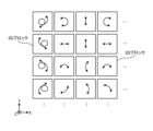
- FIG. 10 is a diagram showing a virtual 3D block preset with a trajectory of an air vehicle
- FIG. 10 is a diagram showing a virtual 3D block preset with a trajectory of an air vehicle
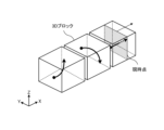
- FIG. 10 is a diagram showing arranged 3D blocks
- FIG. 10 is a diagram showing arranged 3D blocks
- 1 is a diagram illustrating a configuration example of an aircraft control system according to an embodiment of the present disclosure
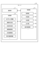
- FIG. 1 is a diagram illustrating a configuration example of a server according to an embodiment of the present disclosure
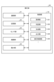
- FIG. 1 is a diagram illustrating a configuration example of a terminal device according to an embodiment of the present disclosure
- FIG. 1 is a diagram showing a configuration example of an aircraft according to an embodiment of the present disclosure
- FIG. 3 is a functional block diagram for explaining functions provided in the information processing apparatus;
- FIG. 10 is a diagram showing a user interface of pattern 1;
- FIG. 10 is a diagram showing a user interface of pattern 2;
- FIG. 10 is a diagram showing a user interface of pattern 3;
- FIG. 4 is a diagram for explaining operations for enlarging and reducing a 3D block; It is a figure for demonstrating operation of rotation of a 3D block.
- FIG. 10 is a diagram for explaining an operation for moving a 3D block;
- FIG. 10 is a diagram for explaining an operation for synthesizing 3D blocks;
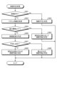
- 4 is a flowchart showing flight path generation processing; 9 is a flowchart showing addition processing; 4 is a flowchart showing insertion processing; 4 is a flowchart showing deletion processing; 6 is a flow chart showing synthesis processing; 4 is a flowchart showing output processing; 9 is a flowchart showing connection determination processing; 9 is a flowchart showing connection trajectory generation processing; 9 is a flowchart showing synthesis determination processing; 9 is a flowchart showing synthetic trajectory generation processing;
- a plurality of components having substantially the same functional configuration may be distinguished by attaching different numerals after the same reference numerals.
- a plurality of configurations having substantially the same functional configurations are distinguished like terminal devices 20 1 and 20 2 as necessary.
- the terminal devices 20 1 and 20 2 are simply referred to as the terminal device 20 when there is no particular need to distinguish between them.
- the flight path of an aircraft is a three-dimensional trajectory. It takes a long time for the user to input a three-dimensional flight path using a two-dimensional screen, for example, it is necessary to perform a viewpoint conversion operation. Generating a flight path for an air vehicle is not an easy task.
- the flying object will be caused to perform the operation desired by the user by storing a preset flight pattern in the flying object and selecting the flight pattern by the user.
- the movement of the flying object becomes monotonous, and the degree of freedom for the user is small.
- multiple flight patterns cannot be executed in succession.
- the information processing device holds in advance a plurality of virtual 3D blocks each preset with the trajectory of the flying object.
- 1A and 1B are diagrams showing virtual 3D blocks in which the trajectory of an air vehicle is preset.
- the X-axis and Y-axis indicate the horizontal direction
- the Z-axis indicates the vertical direction.
- FIG. 1A shows 16 3D blocks viewed from above (Z-axis positive direction).
- FIG. 1B shows three 3D blocks viewed obliquely from above.
- the 3D blocks shown in FIGS. 1A and 1B are both cuboids (or cubes). These 3D blocks are preset with different trajectories, such as turning right, rising, and going straight. Arrows in the 3D blocks indicate the trajectory of the aircraft.
- a 3D block may be preset with a special action such as takeoff, landing, or RTH (Return To Home).
- a predetermined user interface for example, a screen of a dedicated application installed in the information processing device
- the motion is input to the information processing device.
- these 3D blocks may be able to be enlarged, reduced, and rotated as well as moved within the screen.
- the user arranges a plurality of 3D blocks on the screen while enlarging, reducing, rotating or moving the 3D blocks.
- 2A and 2B are diagrams showing arranged 3D blocks.
- FIG. 2A shows how 3D blocks are arranged in a virtual 3D space.
- FIG. 2B also shows how the 3D blocks are arranged in chronological order.
- the information processing device generates the flight path of the aircraft based on the user's input. The aircraft flies according to the generated flight path information.
- the information processing apparatus of this embodiment determines whether or not the two 3D blocks that the user is trying to connect can be connected. Then, the information processing device displays the determination result to the user.
- the information processing apparatus may execute connection determination in advance for all combinations of 3D blocks, and display the combinations of connectable 3D blocks to the user in accordance with the user's operation on the application screen. good. This allows the user to more easily generate the flight path of the air vehicle.
- FIG. 3 is a diagram showing a configuration example of the aircraft control system 1 according to the embodiment of the present disclosure.
- the aircraft control system 1 is an information processing system that performs processing related to the flight of the aircraft 30 .
- the aircraft control system 1 includes a server 10 , a terminal device 20 and an aircraft 30 .
- the devices in the figure may be considered devices in a logical sense. In other words, part of the devices in the figure may be realized by virtual machines (VMs), containers, Dockers, etc., and they may be physically implemented on the same hardware.
- VMs virtual machines
- containers containers
- Dockers etc.
- the server 10 and the terminal device 20 each have a communication function and are connected via a network N.
- the flying object 30 has a wireless communication function and is connected to the terminal device 20 via wireless.
- the aircraft 30 may be configured to be connectable to the network N.
- the server 10, the terminal device 20, and the aircraft 30 can be rephrased as communication devices. Although only one network N is shown in the example of FIG. 3, a plurality of networks N may exist.
- the network N is a communication network such as LAN (Local Area Network), WAN (Wide Area Network), cellular network, fixed telephone network, local IP (Internet Protocol) network, and the Internet.
- the network N may include wired networks or wireless networks.
- Network N may also include a core network.
- the core network is, for example, EPC (Evolved Packet Core) or 5GC (5G Core network).
- the network N may include data networks other than the core network.
- the data network may be a carrier's service network, for example an IMS (IP Multimedia Subsystem) network.
- the data network may also be a private network, such as a corporate network.
- the terminal device 20 and communication devices such as the aircraft 30 use radio access technology (RAT: Radio Access Technology) such as LTE (Long Term Evolution), NR (New Radio), Wi-Fi, Bluetooth (registered trademark), etc. may be configured to connect to a network N or other communication device using the At this time, the communication device may be configured to be able to use different radio access technologies.
- the communication device may be configured with NR and Wi-Fi enabled.
- the communication device may be configured to use different cellular communication technologies (eg, LTE and NR).
- LTE and NR are a type of cellular communication technology, and by arranging a plurality of areas covered by base stations in a cell, mobile communication of communication devices is enabled.
- Communication devices such as the server 10, the terminal device 20, and the aircraft 30 can be connected to the network N or other communication devices using radio access technologies other than LTE, NR, Wi-Fi, and Bluetooth. good.
- a communication device may be connectable to a network N or other communication device using LPWA (Low Power Wide Area) communication.
- the communication device may also be connectable to a network N or other communication device using proprietary wireless communication.
- the communication device may be connectable to the network N or other communication device using other known standards of wireless communication.
- each device that constitutes the aircraft control system 1 will be specifically described below. Note that the configuration of each device shown below is merely an example. The configuration of each device may differ from the configuration shown below.
- the server 10 is an information processing device (computer) that performs processing related to flight control of the aircraft 30 .
- the server 10 is a computer that performs automatic flight processing of the aircraft 30 .
- the server 10 can employ any form of computer.
- server 10 may be a PC server, a midrange server, or a mainframe server.
- FIG. 4 is a diagram showing a configuration example of the server 10 according to the embodiment of the present disclosure.
- the server 10 includes a communication section 11 , a storage section 12 and a control section 13 .
- the configuration shown in FIG. 4 is a functional configuration, and the hardware configuration may differ from this.
- the functions of the server 10 may be distributed and implemented in a plurality of physically separated configurations.
- the server 10 may be composed of a plurality of server devices.
- the communication unit 11 is a communication interface for communicating with other devices.
- the communication unit 11 is a LAN (Local Area Network) interface such as a NIC (Network Interface Card).
- the communication unit 11 may be a wired interface or a wireless interface.
- the communication unit 11 communicates with the terminal device 20, the aircraft 30, etc. under the control of the control unit 13.
- FIG. 1 A block diagram illustrating an exemplary computing environment in accordance with the present invention.
- the storage unit 12 is a data readable/writable storage device such as a DRAM (Dynamic Random Access Memory), an SRAM (Static Random Access Memory), a flash memory, a hard disk, or the like.
- the storage unit 12 functions as storage means of the server 10 .
- the storage unit 12 stores various types of information such as 3D block information, a connection correspondence table, a synthesis correspondence table, a connection result table, a synthesis result table, and flight route information.
- the control unit 13 is a controller that controls each unit of the server 10 .
- the control unit 13 is implemented by a processor such as a CPU (Central Processing Unit), MPU (Micro Processing Unit), GPU (Graphics Processing Unit), or the like.
- the control unit 13 is implemented by the processor executing various programs stored in the storage device inside the server 10 using a RAM (Random Access Memory) or the like as a work area.
- the control unit 13 may be realized by an integrated circuit such as ASIC (Application Specific Integrated Circuit) or FPGA (Field Programmable Gate Array).
- ASIC Application Specific Integrated Circuit
- FPGA Field Programmable Gate Array
- the control unit 13 includes an acquisition unit 131 , a determination unit 132 , a generation unit 133 , an output unit 134 and a display control unit 135 .
- Each block (acquisition unit 131 to display control unit 135) constituting the control unit 13 is a functional block indicating the function of the control unit 13.
- FIG. These functional blocks may be software blocks or hardware blocks.
- each of the functional blocks described above may be one software module realized by software (including microprograms), or may be one circuit block on a semiconductor chip (die). Of course, each functional block may be one processor or one integrated circuit.
- the control unit 13 may be configured in functional units different from the functional blocks described above. The configuration method of the functional blocks is arbitrary.
- control unit 13 may be configured in functional units different from the functional blocks described above. Also, some or all of the blocks (acquisition unit 131 to display control unit 135) constituting the control unit 13 may be performed by another device. For example, one or a plurality of control units selected from the control unit 23 of the terminal device 20 and the control unit 33 of the aircraft 30 perform part or all of the operation of each block that configures the control unit 13. may The operation of each block constituting the control unit 13 will be described later.
- the terminal device 20 is a communication device that communicates with the server 10 and the aircraft 30.
- the terminal device 20 is a terminal possessed by a user who operates the aircraft 30 .
- the terminal device 20 transmits control information for the user to control the flying object 30 to the flying object 30 .
- the terminal device 20 also receives, for example, the current state of the flying object 30 (for example, information on the position and attitude of the flying object 30) from the flying object 30.
- the terminal device 20 is configured to exchange information for controlling the flying object 30 (for example, information for automatic flight control of the flying object 30 and information for estimating the position and attitude of the flying object 30) with the server 10. may
- the terminal device 20 is, for example, a proportional system used by the user to operate the aircraft 30.
- the terminal device 20 is not limited to a proportional system, and may be, for example, a mobile phone, a smart device (smartphone or tablet), a PDA (Personal Digital Assistant), or a personal computer.
- the terminal device 20 is not limited to a smart device or personal computer, and may be a controller with a display or a joystick with a display.
- the terminal device 20 may be an imaging device (for example, a camcorder) equipped with a communication function, or a mobile body (for example, a motorcycle or a mobile relay station) equipped with a communication device such as an FPU (Field Pickup Unit). car).
- the terminal device 20 may be an M2M (Machine to Machine) device or an IoT (Internet of Things) device.
- the terminal device 20 may be a router.
- the terminal device 20 may be an xR device such as an AR (Augmented Reality) device, a VR (Virtual Reality) device, or an MR (Mixed Reality) device.
- the terminal device 20 may be a wearable device such as a smart watch.
- FIG. 5 is a diagram showing a configuration example of the terminal device 20 according to the embodiment of the present disclosure.
- the terminal device 20 includes a communication section 21 , a storage section 22 , a control section 23 , a sensor section 24 , an operation section 25 and a display section 26 .
- the configuration shown in FIG. 5 is a functional configuration, and the hardware configuration may differ from this. Also, the functions of the terminal device 20 may be distributed and implemented in a plurality of physically separated configurations.
- the communication unit 21 is a communication interface for communicating with other devices.
- the communication unit 21 is a LAN interface such as NIC.
- the communication unit 21 may be a wired interface or a wireless interface.
- the communication unit 21 communicates with the server 10, the aircraft 30, etc. under the control of the control unit 23. FIG.
- the storage unit 22 is a data readable/writable storage device such as a DRAM, SRAM, flash memory, or hard disk.
- the storage unit 22 functions as storage means of the terminal device 20 .
- the storage unit 22 stores, for example, feature point maps.
- the control unit 23 is a controller that controls each unit of the terminal device 20 .
- the control unit 23 is implemented by a processor such as a CPU, MPU, or GPU, for example.
- the control unit 23 is implemented by the processor executing various programs stored in the storage device inside the terminal device 20 using the RAM or the like as a work area.
- the control unit 23 may be realized by an integrated circuit such as ASIC or FPGA. CPUs, MPUs, GPUs, ASICs, and FPGAs can all be considered controllers.
- the control unit 23 includes an acquisition unit 231 , a determination unit 232 , a generation unit 233 , an output unit 234 and a display control unit 235 .
- Each block (acquisition unit 231 to display control unit 235) constituting the control unit 23 is a functional block indicating the function of the control unit 23.
- FIG. These functional blocks may be software blocks or hardware blocks.
- each of the functional blocks described above may be one software module realized by software (including microprograms), or may be one circuit block on a semiconductor chip (die). Of course, each functional block may be one processor or one integrated circuit.
- the control unit 23 may be configured in functional units different from the functional blocks described above. The configuration method of the functional blocks is arbitrary.
- control unit 23 may be configured in functional units different from the functional blocks described above. Also, some or all of the blocks (acquisition unit 231 to display control unit 235) constituting the control unit 23 may be performed by another device. For example, one or a plurality of control units selected from the control unit 13 of the server 10 and the control unit 33 of the aircraft 30 perform a part or all of the operations of each block constituting the control unit 23. good too.
- the sensor unit 24 is a sensor that acquires information regarding the position or orientation of the terminal device 20 .
- the sensor unit 24 is a GNSS (Global Navigation Satellite System) sensor.
- the GNSS sensor may be a GPS (Global Positioning System) sensor, a GLONASS sensor, a Galileo sensor, or a QZSS (Quasi-Zenith Satellite System) sensor.
- GPS Global Positioning System
- GLONASS Global Navigation Satellite System
- Galileo Galileo
- QZSS Quadasi-Zenith Satellite System
- a GNSS sensor can be restated as a GNSS receiver module.
- the sensor unit 24 is not limited to the GNSS sensor, and may be, for example, an acceleration sensor.
- the sensor unit 24 may be a combination of a plurality of sensors.
- the operation unit 25 is an operation device for the user to perform various operations.
- the operation unit 25 includes levers, buttons, a keyboard, a mouse, operation keys, and the like.
- the touch panel is also included in the operation unit 25 . In this case, the user performs various operations by touching the screen with a finger or a stylus.
- the display unit 26 is a display device that displays various information.
- the display device is, for example, a liquid crystal display or an organic EL display.
- the display unit 26 may be a touch panel type display device.
- the display section 26 also functions as an input section (for example, the operation section 25).
- the flying object 30 is configured so that the user can manually operate it from a remote location using the terminal device 20 .
- Air vehicle 30 may be configured to fly automatically.
- the air vehicle 30 may be configured to automatically fly along a user-generated flight path.
- the flying object 30 is typically a drone, but does not necessarily have to be a drone.
- the flying object 30 may be a mobile object that moves in the atmosphere other than a drone.
- the air vehicle 30 may be an aircraft such as an airplane, an airship, or a helicopter.
- the concept of aircraft includes not only heavy aircraft such as airplanes and gliders, but also light aircraft such as balloons and airships.
- the concept of aircraft includes not only heavy aircraft and light aircraft, but also rotorcraft such as helicopters and autogyros.
- the flying object 30 may be a manned aircraft or an unmanned aircraft.
- unmanned aircraft includes unmanned aircraft systems (UAS) and tethered unmanned aerial systems (tethered UAS).
- unmanned aerial vehicles includes light unmanned aerial systems (LTA: Lighter than Air UAS) and heavy unmanned aerial systems (HTA: Heavier than Air UAS).
- LTA Lighter than Air UAS
- HTA Heavier than Air UAS
- the concept of unmanned aircraft also includes high altitude unmanned aerial system platforms (HAPs: High Altitude UAS Platforms).
- a drone is a type of unmanned aerial vehicle.
- the flying object 30 may be a moving object that moves outside the atmosphere.
- the flying object 30 may be an artificial celestial body such as an artificial satellite, spacecraft, space station, probe, or the like.
- FIG. 6 is a diagram showing a configuration example of the flying object 30 according to the embodiment of the present disclosure.
- the flying object 30 includes a communication unit 31, a storage unit 32, a control unit 33, a sensor unit 34, an imaging unit 35, and a power unit 36.
- the configuration shown in FIG. 6 is a functional configuration, and the hardware configuration may differ from this. Also, the functions of the vehicle 30 may be distributed and implemented in multiple physically separated configurations.
- the communication unit 31 is a communication interface for communicating with other devices.
- the communication unit 31 is a LAN interface such as NIC.
- the communication unit 31 may be a wired interface or a wireless interface.
- the communication unit 31 communicates with the server 10 , the terminal device 20 , the aircraft 30 and the like under the control of the control unit 33 .
- the storage unit 32 is a data readable/writable storage device such as a DRAM, SRAM, flash memory, or hard disk.
- the storage unit 32 functions as storage means for the aircraft 30 .
- the storage unit 32 stores, for example, a feature point map.
- the control unit 33 is a controller that controls each part of the flying object 30 .
- the control unit 33 is implemented by a processor such as a CPU, MPU, or GPU, for example.
- the control unit 33 is implemented by the processor executing various programs stored in the storage device inside the aircraft 30 using the RAM or the like as a work area.
- the control unit 33 may be realized by an integrated circuit such as ASIC or FPGA. CPUs, MPUs, GPUs, ASICs, and FPGAs can all be considered controllers.
- the control unit 33 includes an acquisition unit 331 , a determination unit 332 , a generation unit 333 , an output unit 334 and a display control unit 335 .
- Each block (acquisition unit 331 to display control unit 335) constituting the control unit 33 is a functional block indicating the function of the control unit 33.
- FIG. These functional blocks may be software blocks or hardware blocks.
- each of the functional blocks described above may be one software module realized by software (including microprograms), or may be one circuit block on a semiconductor chip (die). Of course, each functional block may be one processor or one integrated circuit.
- the control unit 33 may be configured in functional units different from the functional blocks described above. The configuration method of the functional blocks is arbitrary.
- control unit 33 may be configured in functional units different from the functional blocks described above. Also, some or all of the blocks (acquisition unit 331 to display control unit 335) that make up the control unit 33 may be performed by another device. For example, one or a plurality of control units selected from the control unit 13 of the server 10 and the control unit 23 of the terminal device 20 perform part or all of the operations of each block that constitutes the control unit 33. good too.
- the imaging unit 35 is a conversion unit that converts an optical image into an electrical signal.
- the imaging unit 35 includes, for example, an image sensor and a signal processing circuit that processes analog pixel signals output from the image sensor, and converts light entering from the lens into digital data (image data).
- image data digital data
- the image captured by the imaging unit 35 is not limited to a video (moving image), and may be a still image.
- the imaging unit 35 may be a camera. At this time, the imaging unit 35 can be called an FPV (First Person View) camera.
- FPV First Person View
- the sensor unit 34 is a sensor that acquires information regarding the position or attitude of the flying object 30 .
- sensor unit 34 is a GNSS sensor.
- the GNSS sensor may be a GPS sensor, a GLONASS sensor, a Galileo sensor, or a QZSS sensor.
- a GNSS sensor can be restated as a GNSS receiver module.
- the sensor unit 34 is not limited to the GNSS sensor, and may be, for example, an acceleration sensor.
- the sensor section 34 may be an IMU (Inertial Measurement Unit), a barometer, a geomagnetic sensor, or an altimeter.
- the sensor unit 34 may be a combination of a plurality of sensors.
- the sensor unit 34 may be a sensor for generating 3D map information. More specifically, the sensor unit 34 may be a sensor that reads the three-dimensional structure of the surrounding environment.
- the sensor unit 34 may be a depth sensor such as LiDAR (light detection and ranging).
- the sensor unit 24 may be a depth sensor other than the LiDAR.
- the sensor unit 34 may be a distance measurement system using millimeter wave radar.
- the sensor unit 34 may be a ToF (Time of Flight) sensor or a stereo camera.
- the power unit 36 is power that enables the flying object 30 to fly.
- the power unit 36 is a motor that drives various mechanisms included in the aircraft 30 .
- FIG. 7 is a functional block diagram for explaining functions provided in the information processing apparatus.
- the functions provided by the information processing apparatus of this embodiment are divided into the following (1) to (5).
- the generation and output of flight route information is realized by the cooperation of functional blocks shown in (1) to (5) below.
- the acquisition unit may be the acquisition unit 131 of the server 10, the acquisition unit 231 of the terminal device 20, or the acquisition unit 331 of the aircraft 30.
- the determination unit may be the determination unit 132 of the server 10 , the determination unit 232 of the terminal device 20 , or the determination unit 332 of the aircraft 30 .
- the generation unit may be the generation unit 133 of the server 10 , the generation unit 233 of the terminal device 20 , or the generation unit 333 of the aircraft 30 .
- the output unit may be the output unit 134 of the server 10 , the output unit 234 of the terminal device 20 , or the output unit 334 of the aircraft 30 .
- the display control unit may be the display control unit 135 of the server 10 , the display control unit 235 of the terminal device 20 , or the display control unit 335 of the aircraft 30 .
- the information processing device also includes a storage unit that stores various types of information for the control unit to generate information on the flight path of the aircraft 30 .
- the storage unit may be the storage unit 12 of the server 10 , the storage unit 22 of the terminal device 20 , or the storage unit 22 of the aircraft 30 .
- Various types of information such as 3D block information, connection correspondence table, synthesis correspondence table, connection result table, synthesis result table, and flight route information are stored in the storage unit.
- the acquisition unit acquires operation information input by the user by operating the operation unit (for example, the operation unit 25 of the terminal device 20).
- the operation information is information on a user's operation to one or a plurality of 3D blocks selected from among a plurality of virtual 3D blocks each preset with a trajectory of the flying object.
- the operation information is operations such as moving, enlarging, reducing, rotating, and synthesizing 3D blocks.
- the acquisition unit acquires 3D block information of each 3D block used to generate the flight path from the storage unit.
- the 3D block information is trajectory information preset in 3D blocks.
- the trajectory information is, for example, information on reference coordinates, trajectory shape, start position/attitude velocity, and end position/attitude velocity.
- the 3D block information may include information of icons assigned to the 3D blocks.
- the determining unit determines whether or not connection processing of two or more 3D blocks is possible. For example, the determination unit determines whether or not two 3D blocks selected from a plurality of virtual 3D blocks are connectable. The determination unit also determines whether or not the flying object 30 needs to be paused between the two 3D blocks in order to connect the two 3D blocks. In addition, the determination unit determines whether deformation processing of at least one of the two 3D blocks is required to connect the two 3D blocks. Also, the determination unit determines a combination of connectable 3D blocks from among the plurality of virtual 3D blocks.
- the determination unit may realize these determinations by calculation based on the 3D block information, or by referring to information (for example, a connection correspondence table) stored in advance in the storage unit.
- the connection correspondence table is a table showing connection methods between 3D blocks.
- the connection correspondence table shows the following information for all combinations of 3D blocks. ⁇ Can be connected without deformation or stopping ⁇ If deformed, can be connected without stopping ⁇ Can be connected if paused ⁇ Cannot be connected (or meaningless)
- the determination unit makes the above determination by referring to the information in the corresponding portion of the connection correspondence table.
- the determination unit determines whether or not two or more 3D blocks can be synthesized. For example, the determining step determines whether two 3D blocks selected from among a plurality of virtual 3D blocks are combinable. Also, the determination unit determines a combination of 3D blocks that can be synthesized from among the plurality of virtual 3D blocks.
- the determination unit may realize these determinations by calculation based on 3D block information, or based on information (for example, synthesis correspondence table) stored in advance in the storage unit.
- the compositing correspondence table is a table showing a compositing method between 3D blocks.
- the synthesis correspondence table shows the following information for all combinations of 3D blocks. ⁇ Synthesizable ⁇ Synthesizable (or meaningless)
- the determination unit makes the above determination by referring to the information in the relevant portion of the synthesis correspondence table.
- the generating unit executes connection processing of a plurality of 3D blocks based on the operation information acquired by the acquiring unit. For example, the generation unit executes connection processing of two 3D blocks specified based on the operation information. The generation unit may implement this process by calculation based on the 3D block information, or by referring to information (for example, a connection result table) stored in advance in the storage unit.
- the connection result table is a table showing connection results between 3D blocks. For example, the connection correspondence table shows trajectory information indicating the result of connecting two 3D blocks for all combinations of 3D blocks.
- the generator connects the two 3D blocks by referring to the information in the corresponding part of the connection result table.
- the generation unit executes a process of synthesizing a plurality of 3D blocks based on the operation information acquired by the acquisition unit. For example, the generation unit executes a synthesis process of two 3D blocks specified based on the operation information. The generation unit may implement this processing by calculation based on the 3D block information, or by referring to information (for example, synthesis result table) stored in advance in the storage unit.
- the synthesis result table is a table showing the synthesis results of 3D blocks.
- the connection correspondence table shows trajectory information indicating the result of synthesizing two 3D blocks for all combinations of 3D blocks.
- the generation unit synthesizes two 3D blocks by referring to the information in the corresponding part of the connection result table.
- the output unit outputs information on the flight path of the aircraft generated based on the processing result of the generation unit.
- the output unit may output the flight route information to the storage unit or to the display device.
- the output unit may display a plurality of connected or combined 3D blocks in a virtual 3D space corresponding to the real space. Also, the output unit may display a plurality of connected or combined 3D blocks in chronological order.
- the display control unit displays the determination result of the determination unit.
- the display control unit displays a user interface for the user to perform an operation on one or more 3D blocks, and displays the determination result on the user interface.
- the display control unit displays the determination result as to whether or not the two 3D blocks are connectable. For example, the display control unit displays information on combinations of connectable 3D blocks as the determination result. The display control unit displays the determination result as to whether or not the pause operation is required. The display control unit displays, as a determination result, information on a combination of 3D blocks that can be connected without requiring a pause operation. The display control unit displays the determination result as to whether or not transformation processing is required. The display control unit displays, as a determination result, information on combinations of 3D blocks that can be connected without deformation.
- the display control unit displays the determination result as to whether or not the two 3D blocks can be combined. For example, the display control unit displays information on combinations of 3D blocks that can be combined as the determination result.
- UIs user interfaces
- FIG. 8 is a diagram showing the user interface of pattern 1.
- the UI of pattern 1 has a chronological display area and a list display area, as shown in FIG. 8, for example.
- the chronological display area is an area in which a plurality of 3D blocks selected and arranged by the user are displayed along time t.
- the list display area is an area in which a list of a plurality of 3D blocks prepared in advance is displayed. It should be noted that a plurality of 3D blocks may be displayed in a page-divided or hierarchized manner in the list display area.
- the plurality of 3D blocks displayed in the list display area may be displayed so that the methods that can be connected or combined can be identified.
- 3D blocks that can be connected/synthesized may be suggested and displayed so as to make them stand out. The user selects a 3D block from the list display area and arranges it in the chronological display area. The user drags and drops the 3D blocks displayed in the list display area to the chronological display area.
- FIG. 9 is a diagram showing a pattern 2 user interface.
- the UI of pattern 2 a plurality of connected or combined 3D blocks are displayed in a virtual 3D space corresponding to the real space.
- the UI of pattern 2 has a 3D space display area and a list display area, as shown in FIG. 9, for example.
- the 3D space display area is an area where a 3D space such as a 3D map is displayed.
- a 3D block selected by the user from the list display area can be arranged in the 3D space display area.
- the list display area is an area in which a list of a plurality of 3D blocks prepared in advance is displayed.
- the list display area is the same as the list display area of pattern 1 .
- the user drags and drops the 3D blocks displayed in the list display area to the 3D space display area.
- FIG. 10 is a diagram showing the user interface of pattern 3.
- a plurality of connected or synthesized 3D blocks are displayed in chronological order and also displayed in a virtual 3D space.
- the UI of pattern 3 has, for example, a chronological display area, a 3D space display area, and a list display area, as shown in FIG.
- the time-series display area, 3D space display area, and list display area are the same as the time-series display area, 3D space display area, and list display area of Pattern 1 or Pattern 2 .
- the 3D block selected by the user from the list display area is arranged in the 3D space display area or the time-series display area
- the 3D block is arranged in another display area (the time-series display area or the 3D space display area). be.
- the current point in time is displayed in the time-series display area or the 3D space display area.
- the user can perform the following operations (1) to (5) on the 3D block, for example.
- (1) to (5) will be described below.
- FIG. 11 is a diagram for explaining operations for enlarging and reducing 3D blocks.
- the information processing apparatus may limit the operations that the user can perform to enlargement and reduction in three directions (X-axis direction, Y-axis direction, and Z-axis direction). By limiting the degree of freedom of user operations, it becomes easier to perform 3D operations without performing viewpoint operations on a 2D screen, and it is possible to reduce the time taken to create a trajectory.
- FIG. 12 is a diagram for explaining the operation of rotating the 3D block.
- the information processing device may limit the operation that the user can perform to rotation by selecting an axis (X-axis, Y-axis, Z-axis). By limiting the degree of freedom of user operation, the operation becomes easier, and as a result, it becomes possible to reduce the trajectory creation time.
- FIG. 13 is a diagram for explaining an operation for moving a 3D block.
- the information processing apparatus may limit the operations that the user can perform to movement in three directions (X-axis direction, Y-axis direction, and Z-axis direction). By limiting the degree of freedom of user operation, the operation becomes easier, and as a result, it becomes possible to reduce the trajectory creation time.
- FIG. 14 is a diagram for explaining the operation of synthesizing 3D blocks.
- the user combines one of the 3D blocks arranged in the 3D space display area with one of the 3D blocks displayed in the list display area.
- the information processing device may display which 3D block in the list display area can be combined with the 3D block.
- the information processing apparatus may highlight only 3D blocks that can be combined, and gray out 3D blocks that cannot be combined.
- addition of 3D blocks For example, the user can add one or more 3D blocks to the end of multiple 3D blocks displayed in a connected state in the chronological display area or the 3D spatial display area.
- the information processing apparatus may determine the connection between the end block and the additional block, and perform the additional processing when the connection is possible.
- the user can add one or more 3D blocks to the beginning of the plurality of 3D blocks displayed in the connected state in the time series display area or 3D space display area.
- the information processing device may determine the connection between the leading block and the additional block, and perform the additional processing when the connection is possible.
- the user can insert a 3D block in the middle of a plurality of 3D blocks displayed in a connected state in the time series display area or the 3D space display area.
- the information processing apparatus may determine the connection between the 3D blocks before and after the insertion point and the insertion block, and may perform the insertion process when the connection is possible.
- the user can delete one or more 3D blocks from the plurality of 3D blocks displayed in the connected state in the time series display area or the 3D space display area.
- the information processing device may determine the connection between the 3D blocks before and after the block to be deleted, and perform the deletion process when the 3D blocks are connectable.
- the information processing device may display an editing method. For example, if the user's operation is to enlarge or reduce a 3D block, the information processing device displays a line indicating a direction in which enlargement or reduction is possible (a thick line with a black dot at the tip shown in FIG. 11) at a representative position of the 3D block. ) may be displayed. Also, if the user's operation is to rotate the 3D block, a line (bold line shown in FIG. 12) may be displayed around the 3D block to indicate the direction in which rotation is possible. Also, if the user's operation is to move the 3D block, an arrow (thick arrow shown in FIG. 13) indicating the direction in which movement is possible may be displayed at the representative position of the 3D block. Also, if the user's operation is to connect 3D blocks, the information processing apparatus may highlight surfaces to which 3D blocks can be connected.
- the 3D block information is trajectory information preset in the 3D block.
- the 3D block information includes, for example, information (1) to (5) below.
- the information processing device updates the following information (1) to (5) according to the user's operation on the 3D block.
- Graphic Information Graphic information is information of graphics of 3D blocks displayed on the screen.
- Representative Position Information is position information of a representative point of a 3D block.
- the representative position information is, for example, coordinate information (x, y, z) with the upper right corner of the 3D block as the origin.
- the initial value is (0, 0, 0), for example, and can be changed by the user.
- the information processing device executes processing for moving to a 3D block based on this representative position.
- Posture Information is information indicating the current posture of the 3D block.
- the orientation information is, for example, information indicating how much the 3D block has rotated from the reference orientation (an initial orientation in which no rotation operation has been performed).
- the format of the orientation information may be (roll, pitch, yaw) or (x, y, z, w).
- the initial value is, for example, (0,0,0) or (0,0,0,1).
- the information processing device updates the posture information according to the operation.
- Scale information is information indicating the current size of a 3D block.
- the orientation information is, for example, information indicating how much the 3D block has been enlarged or reduced in the axial direction from the reference size (the size in the initial state where no enlargement or reduction operation has been performed).
- the format of scale information is, for example, (x, y, z).
- the initial value is, for example, (1, 1, 1).
- the trajectory composing point sequence information is trajectory composing point sequence information indicating a trajectory preset in a 3D block.
- the trajectory point sequence information is, for example, arrangement information of the following information (position/orientation information and velocity information).
- the information processing device updates the trajectory point sequence information according to the operation.
- Position and orientation information consists of position information and orientation information.
- the position information is, for example, information on the relative positions (x, y, z) of the trajectory composing points with reference to the representative position information of the 3D blocks.
- the attitude information is information on the attitude of the flying object 30 traveling along the trajectory (trajectory composing point sequence) at the corresponding trajectory composing point.
- the attitude information is, for example, the relative attitude ((roll, pitch, yaw) or (x, y, z, w)) information.
- Velocity information is information on the velocity at the corresponding trajectory composing point of the flying object 30 traveling along the trajectory (orbital composing point sequence).
- the velocity information is composed of, for example, translational velocity (x, y, z) and rotational velocity (roll, pitch, yaw) information.
- the processing of the information processing device described below may be executed by any one of the plurality of devices (the server 10, the terminal device 20, and the aircraft 30) constituting the aircraft control system 1, or the aircraft control
- the control units (information processing devices) of a plurality of devices forming the system 1 may cooperate to execute.
- FIG. 15 is a flowchart showing flight path generation processing.
- the flight path generation processing is processing for generating the flight path of the aircraft 30 .
- the information processing device starts flight route generation processing when a user starts an application for flight route generation.
- the flight path generation process will be described below with reference to the flowchart of FIG. 15 .
- the information processing device executes initial processing (step S1). For example, the information processing apparatus displays application screens such as those shown in FIGS. 8 to 10 on the screen (for example, the display unit 26). At this time, the information processing device may display a list of 3D blocks that can be selected by the user on the application screen. The information processing device also initializes the flight route information stored in the storage unit.
- the information processing device determines whether the user has operated the 3D block (step S2). If the operation has not been performed (step S2: No), the information processing device waits until the operation is performed. If an operation has been performed (step S2: Yes), the information processing device acquires operation information indicating the user's operation on the 3D block (step S3).
- the information processing device determines whether the user's operation indicated by the operation information is to add a 3D block (step S4). If the user's operation is to add a 3D block (step S4: Yes), the information processing apparatus executes 3D block addition processing (step S5). Additional processing will be described later.
- step S4 determines whether the user's operation indicated by the operation information is to insert a 3D block (step S6). If the user's operation is to insert a 3D block (step S6: Yes), the information processing device executes 3D block insertion processing (step S7). Insert processing will be described later.
- step S6 determines whether the user's operation indicated by the operation information is to delete a 3D block (step S8). If the user's operation is to delete a 3D block (step S8: Yes), the information processing device executes deletion processing (step S9). The deletion process will be described later.
- step S8 determines whether the user's operation indicated by the operation information is to combine the 3D blocks (step S10). If the user's operation is to synthesize 3D blocks (step S10: Yes), the information processing apparatus executes 3D block synthesis processing (step S11). The synthesizing process will be described later.
- the information processing device determines whether the user's operation indicated by the operation information is to move 3D blocks (step S12). If the user's operation is to move the 3D block (step S12: Yes), the information processing device moves the 3D block displayed in a predetermined area (for example, a time-series display area or a 3D space display area) of the application screen according to the user's operation. Move the block (step S13). For example, the information processing device determines the amount of movement of the selected 3D block based on the operation information, and adds the determined amount of movement to the representative position information of the selected 3D block.
- a predetermined area for example, a time-series display area or a 3D space display area
- the information processing device determines whether the user's operation indicated by the operation information is to rotate the 3D block (step S14). If the user's operation is to rotate the 3D block (step S14: Yes), the information processing device rotates the 3D block displayed in a predetermined area (eg, 3D space display area) of the application screen according to the user's operation (step S15). For example, the information processing device determines the amount of rotation of the selected 3D block based on the operation information, and adds the determined amount of rotation to the posture information of the selected 3D block.
- a predetermined area eg, 3D space display area
- the information processing device determines whether the user's operation indicated by the operation information is deformation (for example, enlargement or reduction) of the 3D block (step S16). ). If the user's operation is to transform the 3D block (step S16: Yes), the information processing device transforms the 3D block displayed in a predetermined area (eg, 3D space display area) of the application screen according to the user's operation (step S17). For example, if the transformation is enlargement or reduction, the information processing device acquires information on the scale (x, y, z) after transformation of the selected 3D block based on the operation information, and Replace the scale information of the 3D block with the determined scale information.
- a predetermined area eg, 3D space display area
- step S18 determines whether the user's operation indicated by the operation information is completion of the flight route creation (step S18). If the user's operation does not indicate completion of flight route creation (step S18: No), the information processing apparatus returns to step S2 and waits for user's operation. If the user's operation is to complete the creation of the flight route (step S18: Yes), the information processing device executes flight route information output processing (step S19). The output processing will be described later.
- the information processing device After the output processing, the information processing device ends the flight route generation processing.
- step S5 Next, the additional processing in step S5 will be described.
- the adding process is a process of adding one or more 3D blocks selected by the user to, for example, a plurality of 3D blocks displayed in a connected state in the time-series display area or the 3D space display area according to the user's operation. be.
- the adding process is assumed to be a process of adding a 3D block to the end of a plurality of 3D blocks.
- the adding process described below can be modified to add a 3D block to the beginning of a plurality of 3D blocks.
- FIG. 16 is a flowchart showing addition processing. The addition process will be described below with reference to the flowchart of FIG. 16 .
- the information processing device acquires information on the 3D block to be added (hereinafter referred to as an additional block) (step S101).
- the information processing device determines whether or not the length of the flight route that has already been created (hereinafter referred to as the created trajectory) is 0 (step S102). For example, it is determined whether or not the number of 3D blocks already displayed in the time series display area or 3D space display area of the application screen is zero.
- the information processing device initializes the created trajectory with additional blocks (step S103).
- step S102 the information processing device acquires information on the trailing 3D block (hereinafter referred to as the trailing block) of the created trajectory (step S104). Then, the information processing device determines the connection between the additional block and the end block (step S105). At this time, the determination result may be any of the following (1) to (4).
- Connectable without deformation and stop means that without deforming the trajectory of the two 3D blocks and without inserting a stop motion of the flying object 30 between the two 3D blocks, Indicates that two 3D blocks can be connected.
- the information processing device outputs the judgment result. For example, the information processing device displays the determination result on a user interface (application screen). Note that if the determination result is (1) to (3) that the connection is possible, a display asking the user whether or not to execute the connection may be made. At this time, if the determination result is (2), it is displayed that the connection requires deformation of the trajectory or temporary stop of the flying object 30 . If the determination result is (3), it is displayed that the aircraft 30 needs to be temporarily stopped to connect the two 3D blocks.
- the information processing device changes the display of the additional block according to the connectable method (step S106). Then, the information processing device connects the additional block to the end block (step S107). The information processing device updates the flight route information to information after connection.
- the information processing device may add connection trajectory information in which the trajectory of the additional block and the trajectory of the last block are smoothly connected to the relevant portion of the flight route information. At this time, the information processing device may modify the trajectory of at least one of the trailing block and the additional block in order to smoothly connect the trailing block trajectory and the additional block trajectory.
- the information processing device After completing the update of the flight route information, the information processing device returns to the flight route generation processing.
- FIG. 17 is a flowchart showing insert processing. The inserting process will be described below with reference to the flowchart of FIG.
- the information processing device acquires information on a 3D block to be inserted (hereinafter referred to as an insertion block) (step S201).
- the information processing device acquires information on the insertion point (step S202). Then, the information processing device acquires information on 3D blocks before and after the insertion point (hereinafter referred to as "before and after blocks") (step S203). Then, the information processing device determines connection between the insertion block and each of the preceding and succeeding blocks (step S204). At this time, the determination result may be any of the following (1) to (4).
- the information processing device outputs the judgment result. For example, the information processing device displays the determination result on a user interface (application screen). Note that if the determination result is (1) to (3) that the connection is possible, a display asking the user whether or not to execute the connection may be made. At this time, if the determination result is (2), it is displayed that the connection requires deformation of the trajectory or temporary stop of the flying object 30 . If the determination result is (3), it is displayed that the aircraft 30 needs to be temporarily stopped to connect the two 3D blocks.
- the information processing device changes the display of the insertion block according to the connectable method (step S205). Then, the information processing device connects the insertion block to the preceding and succeeding blocks (step S206). The information processing device updates the flight route information to information after connection. Note that the information processing device may add connection trajectory information that smoothly connects the preceding and succeeding blocks to the relevant portion of the flight route information. At this time, the information processing device may transform the trajectory of at least one of the preceding and following blocks in order to smoothly connect the trajectories of the preceding and succeeding blocks.
- the information processing device After completing the update of the flight route information, the information processing device returns to the flight route generation processing.
- step S9 Next, the deletion process of step S9 will be described.
- the deletion process is a process of deleting one or a plurality of 3D blocks from a plurality of 3D blocks displayed in a connected state in, for example, the time-series display area or the 3D space display area, according to the user's operation.
- FIG. 18 is a flowchart showing deletion processing. The deletion process will be described below with reference to the flowchart of FIG.
- the information processing device acquires information on a 3D block to be deleted (hereinafter referred to as a deleted block) (step S301).
- the information processing device acquires information on 3D blocks before and after the deleted portion (hereinafter referred to as "before and after blocks") (step S203). Then, the information processing device determines the connection between the preceding and succeeding blocks (step S204). At this time, the determination result may be any of the following (1) to (4).
- the information processing device When connecting the trajectory of the block to be deleted and the block before and after, if the trajectory has been deformed so as to smoothly connect the trajectory of the block to be deleted and the block before and after the block, the information processing device, before judging the connection, These deformations may be removed in advance and the trajectories of the deleted block and the preceding and following blocks may be returned to the preset trajectories.
- step S304: No If the preceding and succeeding blocks cannot be connected (step S304: No), the information processing device advances the process to step S308. If the preceding and succeeding blocks can be connected (step S304: Yes), the information processing device outputs that the preceding and following blocks are connectable. For example, the information processing apparatus displays on the user interface (application screen) that the preceding and succeeding blocks are connectable (step S305).
- the information processing device displays a display asking the user whether or not to connect the preceding and succeeding blocks.
- the determination result is (2) "Connectable if deformed or stopped”, it is displayed that the trajectory deformation or temporary stop of the flying object 30 is required to connect the front and rear blocks.
- the determination result is (3) "connectable if stopped”, it is displayed that the aircraft 30 needs to be temporarily stopped to connect the front and rear blocks.
- the information processing device acquires the user's selection for the question (step S306).
- the information processing device deletes the relevant 3D block and displays to the user that the preceding and subsequent blocks are not connected (step S308). In this case, the information processing device may display the location where the deleted block was located as the insertion location of the 3D block.
- step S307 the information processing device deletes the corresponding 3D block and connects the preceding and succeeding blocks (step S308).
- the information processing device updates the flight route information to information after connection.
- the information processing device may add connection trajectory information that smoothly connects the preceding and succeeding blocks to the relevant portion of the flight route information.
- the information processing device may transform the trajectory of at least one of the preceding and following blocks in order to smoothly connect the trajectories of the preceding and succeeding blocks.
- the information processing device After completing the update of the flight route information, the information processing device returns to the flight route generation processing.
- Synthesis processing is processing for synthesizing a 3D block selected by a user with one of a plurality of 3D blocks displayed in a connected state in, for example, a time-series display area or a 3D space display area according to a user operation.
- FIG. 19 is a flow chart showing composition processing. The synthesizing process will be described below with reference to the flow chart of FIG.
- the information processing device acquires information on a 3D block to be combined (hereinafter referred to as a combined block) (step S401).
- the information processing device also acquires information on the synthesis target block (step S402).
- the information processing device performs composition determination of the composition block and the composition target block (step S403).
- the synthesis determination is a synthesis block, a synthesis target block, and a synthesis availability determination.
- the determination result is, for example, combining impossible or combining possible. It should be noted that there may be a pattern in which synthesis is possible under conditions such as synthesis being possible if deceleration processing is performed.
- the information processing device displays the judgment result to the user. For example, the information processing device displays the determination result on a user interface (application screen). If the determination result indicates that synthesis is possible (or synthesis is possible if deceleration processing is performed), a display asking the user whether or not to execute connection may be displayed. At this time, if the determination result has a condition such as "synthesis is possible if deceleration processing is performed", the information processing device may display the condition.
- the information processing device changes the display of the synthesized block according to the method that can be synthesized (step S404). Then, the information processing device synthesizes the synthesis block with the synthesis target block (step S405). The information processing device updates the flight route information to the synthesized information.
- the information processing device After completing the update of the flight route information, the information processing device returns to the flight route generation processing.
- the output process is a process for outputting the generated flight route information to the storage unit or the display unit.
- the flight trajectory output to the storage section or display section may be referred to as an output trajectory.
- the aircraft 30 flies based on the output trajectory information.
- FIG. 20 is a flowchart showing output processing. The output processing will be described below with reference to the flowchart of FIG.
- the information processing device initializes the information of the output trajectory (step S501). Then, the information processing device selects one 3D block that has not yet been selected from among the plurality of connected 3D blocks (step S502). Then, the information processing device selects one unselected trajectory composing point from a plurality of trajectory composing points included in the selected 3D block (step S503).
- the plurality of trajectory composing points to be selected may include trajectory composing points of connection trajectory information for smoothly connecting 3D blocks to each other.
- the information processing device calculates information on trajectory composing points (hereinafter referred to as output trajectory composing points) that compose the output trajectory based on the information on the selected trajectory composing points (step S504).
- information on the output trajectory composing point position and information on the output composing point orientation are calculated as the information on the output trajectory composing point.
- the output trajectory composing point position Po and the output composing point attitude Ao can be calculated by the following equations (1) and (2).
- Pb is the block representative point position.
- Vc is a vector from the block representative point to the trajectory composing point.
- Sb is the scale factor.
- Mb is a block orientation matrix.
- a c is the trajectory composing point attitude.
- M s is a scale correction matrix.
- the information processing device adds the output trajectory composing points calculated in step S504 to the output trajectory (step S505).
- step S506 determines whether or not the processing of steps S504 and D505 has been executed for all the trajectory composing points in the selected 3D block. If not executed (step S506: No), the information processing apparatus returns the process to step S503.
- step S506 determines whether the processing from step S503 to step S506 has been executed for all blocks (step S507). If not executed (step S507: No), the information processing apparatus returns the process to step S502.
- step S507 If it is being executed (step S507: Yes), the information processing device outputs information on the created output trajectory to the storage unit or display unit (step S508).
- the information processing device After completing the output, the information processing device returns to the flight route generation process.
- connection determination processing Next, connection determination processing will be described.
- the information processing device determines connection of a plurality of 3D blocks in the above-described processes (eg addition process, insertion process, deletion process).
- An example of connection determination processing used in the above-described processing is shown below.
- the information processing device executes connection determination between two 3D blocks.
- the determination results are the following four types (1) to (4).
- the 3D block shall have the following information (1) to (2) as information related to connection determination (hereinafter referred to as connection permission information).
- Forward connection permission information is information indicating whether or not to permit connection of other blocks in front of this 3D block. Forward connections are basically allowed. However, forward connection of 3D blocks to some special 3D blocks, such as take-off blocks, is disallowed.
- the takeoff block is a 3D block in which the takeoff motion of the aircraft 30 is preset.
- Backward connection permission information is information indicating whether or not to permit connection of other blocks ahead of this 3D block. Backward connections are basically allowed. However, backward connection of 3D blocks to some special 3D blocks, such as landing blocks and RTH (Return To Home) blocks, is not permitted.
- the landing block is a 3D block in which the landing motion of the aircraft 30 is preset.
- the RTH block is a 3D block in which an action of returning the aircraft 30 to the home point is preset.
- the information processing device determines the connection of 3D block B to 3D block A.
- the 3D block A is, for example, a 3D block selected by the user as a target to be connected with a new 3D block from among the plurality of 3D blocks displayed in the time-series display area or the 3D space display area.
- the 3D block B is a 3D block selected by the user as a connection target to the 3D block A from the 3D block list displayed in the list display area.
- FIG. 21 is a flowchart showing connection determination processing. The connection determination process will be described below with reference to the flowchart of FIG.
- the information processing device determines whether connection of 3D block B to 3D block A is permitted based on the connection permission information (step S601). For example, in the information processing apparatus, the backward connection permission information of 3D block A permits connection of the 3D block behind 3D block A, and the forward connection permission information of 3D block B is 3D block B. If the connection of the 3D block ahead of is permitted, it is determined that the connection of 3D block B to 3D block A is permitted. Otherwise, the information processing device determines that connection of 3D block B to 3D block A is not permitted.
- step S601 If the connection of 3D block B to 3D block A is not permitted (step S601: No), the information processing device determines that connection is not possible (step S602).
- the information processing device determines the track end (track composition point) of 3D block A and the track start of 3D block B (track composition point ) acquires the vector information set for each (step S603).
- the vector information is, for example, a six-dimensional vector indicating the velocity (translational velocity, rotational velocity) and acceleration set at the corresponding trajectory composing point.
- the information processing device determines whether the difference between the two vectors is equal to or less than a predetermined threshold (step S604). If it is equal to or less than the threshold (step S604: Yes), the information processing device determines that connection is possible without deformation and stoppage (step S605).
- step S604 the information processing device temporarily creates a connection trajectory connecting the trajectory of 3D block A and the trajectory of 3D block B (step S606). At this time, the information processing device deforms the trajectory of at least one of the 3D blocks A and B in order to connect the trajectories of the 3D blocks A and 3D blocks B smoothly.
- the information processing device determines whether or not the trajectory has been successfully created (step S607). If the creation has not succeeded (step S607: No), the information processing device determines that the connection is possible by inserting a pause action of the flying object 30 between the two 3D blocks (step S608). On the other hand, if the creation is successful (step S607: Yes), the information processing device can deform a part of the trajectory of the two 3D blocks, or perform a pause operation of the flying object 30 between the two 3D blocks. is entered, it is determined that the connection is possible (step S609).
- the information processing device ends the connection determination process.
- connection trajectory generation processing Next, the connection trajectory generation process will be described.
- the information processing device connects trajectories of a plurality of 3D blocks in the above-described processing (eg addition processing, insertion processing, deletion processing).
- trajectories of a plurality of 3D blocks eg addition processing, insertion processing, deletion processing.
- An example of connection trajectory generation processing used in the above-described processing is shown below.
- the information processing device generates a connection trajectory that connects the trajectories of two 3D blocks.
- the following two methods (1) and (2) are conceivable as a method of generating a connecting trajectory.
- the information processing device connects 3D block B to 3D block A for ease of understanding.
- the 3D block A is, for example, a 3D block selected by the user as a target to be connected with a new 3D block from among the plurality of 3D blocks displayed in the time-series display area or the 3D space display area.
- the 3D block B is a 3D block selected by the user as a connection target to the 3D block A from the 3D block list displayed in the list display area.
- FIG. 22 is a flowchart showing connection trajectory generation processing. The connection trajectory generation processing will be described below with reference to the flowchart of FIG. 22 .
- the information processing device determines whether the track ends on the connection side of the two 3D blocks are both straight lines. More specifically, it is determined whether the end of the trajectory of 3D block A is a straight line and the start of the trajectory of 3D block B is a straight line (step S701).
- step S701 If the two trajectory ends are both straight lines (step S701: Yes), the information processing device connects the trajectories of 3D block A and 3D block B by performing clothoid spline interpolation on the trajectory on the plane on which the two straight lines lie. (step S702).
- step S703 If at least one of the two track ends is not straight, that is, if at least one of the two track ends is curved (step S701: No), it is determined whether the two track ends are on the same plane (step S703). ). If the two track ends are on the same plane (step S703: Yes), the information processing device performs clothoid spline interpolation on the trajectory on the plane on which the two track ends are placed to obtain 3D block A and 3D block B. connect the orbits of For example, if two trajectory ends are curved lines, the information processing device connects the trajectories of 3D block A and 3D block B by performing clothoid spline interpolation on the trajectory on the plane on which the two curves lie (step S704).
- step S703 determines that the connecting track cannot be generated (step S705).
- the information processing device may connect the two 3D blocks by inserting a pause motion of the aircraft 30 between the two 3D blocks. Even if the pause operation is not inserted, the processing becomes complicated, but it is possible to connect two 3D blocks. Therefore, even if the two track ends do not lie on the same plane, the information processing device may generate a connecting track according to the user's or developer's selection.
- the information processing device ends the connection trajectory generation process.
- the information processing device performs composition determination of a plurality of 3D blocks in the above-described processing (for example, composition processing).
- composition processing for example, composition processing
- An example of the synthesis determination process used in the above process is shown below.
- the information processing device is assumed to execute a synthesis determination of two 3D blocks. There are two types of judgment results, that is, synthesis is possible and synthesis is not possible.
- the 3D block shall have composition permission information as information related to composition determination.
- the compositing permission information is information indicating whether or not this 3D block is permitted to be composited with other blocks. Synthesis is basically allowed. However, synthesizing 3D blocks into some special 3D blocks, such as takeoff blocks, landing blocks, and RTH blocks, is not permitted.
- the information processing apparatus performs combination determination of 3D block B with 3D block A.
- the 3D block A is, for example, a 3D block selected by the user as a target for synthesizing a new 3D block from among a plurality of 3D blocks displayed in the time-series display area or the 3D space display area.
- the 3D block B is a 3D block selected by the user as a connection target to the 3D block A from the 3D block list displayed in the list display area.
- FIG. 23 is a flowchart showing the composition determination process. The composition determination process will be described below with reference to the flowchart of FIG. 23 .
- the information processing device determines whether composition of 3D block B with 3D block A is permitted based on composition permission information (step S801). For example, the information processing device determines that combining of 3D block B with 3D block A is permitted when both of the combining permission information of 3D block A and 3D block B are permitted for combining. Otherwise, the information processing device determines that combining 3D block B with 3D block A is not permitted.
- step S801 When combining 3D block B with 3D block A is not permitted (step S801: No), the information processing apparatus determines that combining is impossible (step S802).
- step S801 When combining 3D block B with 3D block A is permitted (step S801: Yes), the information processing device acquires information on movement element vectors of each of 3D block A and 3D block B (step S803). Then, the information processing device adds up the two moving element vectors (step S804).
- the information processing device determines whether or not all elements of the summed movement element vector are 1 or less (step S805).
- all elements are less than or equal to 1, it means that the two 3D blocks do not have common elements on each of the X, Y, and X axes, so the two 3D blocks can be combined.
- 3D block A is X-axis motion
- 3D block B is YZ-plane motion
- the two 3D blocks can be combined.
- all the elements are not equal to or less than 1
- step S805 determines that synthesis is impossible.
- step S805 If all the elements are 1 or less (step S805: Yes), the information processing device temporarily creates a composite trajectory by combining the trajectory of 3D block A and the trajectory of 3D block B (step S807).
- the information processing device determines whether or not the synthetic trajectory has been successfully created (step S808). At this time, if the speed (translational speed, rotational speed) and acceleration of the created trajectory do not exceed the threshold, the division processing device determines that the synthetic trajectory has been successfully created. may be determined to have failed to create a composite trajectory.
- step S808 If the synthesis trajectory has been successfully created (step S808: Yes), the information processing device determines that the two 3D blocks can be synthesized (step S809).
- step S808 determines whether or not it is in the deceleration permission mode (step S810).
- step S810 No
- step S810 If the deceleration permission mode is not set (step S810: No), it is determined that the two 3D blocks cannot be combined (step S811).
- step S810 it is determined that two 3D blocks can be synthesized by deceleration processing (step S812). For example, the information processing device determines that the two 3D blocks can be combined by decelerating the whole in accordance with the element that most exceeds the threshold.
- the information processing device ends the connection determination process.
- the information processing device synthesizes a plurality of 3D blocks in the above-described processing (for example, synthesis processing).
- An example of synthetic trajectory generation processing used in the above-described processing is shown below.
- the information processing device generates a composite trajectory by combining trajectories of two 3D blocks.
- the information processing device synthesizes 3D block A and 3D block B.
- the 3D block A is, for example, a 3D block selected by the user as a target for synthesizing a new 3D block from among a plurality of 3D blocks displayed in the time-series display area or the 3D space display area.
- the 3D block B is a 3D block selected by the user as an object to be combined with the 3D block A from the 3D block list displayed in the list display area.
- FIG. 24 is a flowchart showing synthetic trajectory generation processing. The synthetic trajectory generation processing will be described below with reference to the flowchart of FIG. 24 .
- the information processing device calculates the flight time after combining two 3D blocks (step S901).
- the information processing apparatus sets the longer of the flight time of the 3D block A and the flight time of the 3D block B as the combined flight time.
- the information processing device determines whether time adjustment is necessary (step S902).
- the information processing device determines that time adjustment is necessary. is not required.
- step S902 If the time adjustment is not necessary (step S902: No), the information processing device advances the process to step S904. If time adjustment is necessary (step S902: Yes), the information processing apparatus executes time adjustment (step S903). Specifically, the information processing device decelerates the speed of the 3D block with the shorter flight time so that the flight time of the 3D block with the shorter flight time matches the post-combining flight time. For example, if the flight time is to be multiplied by R, the information processing device multiplies the speed by 1/R.
- the information processing device synthesizes the trajectories of the two 3D blocks (step S904). For example, the information processing device uses the flight time as an index, and sums up the position and velocity command values for the trajectory composing points with the same index in two 3D blocks.
- the information processing device outputs the generated synthetic trajectory to the storage unit or the display unit (step S905).
- the information processing device ends the connection trajectory generation process.
- the 3D blocks are rectangular parallelepipeds or cubes, but the 3D blocks are not limited to rectangular parallelepipeds or cubes, and may be, for example, spheres or cylinders.
- the application screen displays a 3D space display area in which 3D blocks can be arranged. Any size grid may be displayed, such as a grid.
- the information processing device may snap the 3D block to the grid when the user moves the 3D block.
- the information processing device may display on the screen an output trajectory generated by connecting or synthesizing 3D blocks by the user. At this time, the information processing device may display the output trajectory with color gradation according to the speed so that the user can understand the speed of the flying object 30 . For example, the information processing device may display the output trajectory with a gradation of green for the highest speed and green for the lowest speed.
- the information processing apparatus displays the determination result as to whether or not two 3D blocks are connectable on the application screen. You may display the information of a combination. For example, the information processing device may perform connection determination for all conceivable combinations of the plurality of 3D blocks displayed in the list display area, and display a list of information on pairs of connectable 3D blocks. . Further, when the user selects one 3D block, one or more 3D blocks connectable to that 3D block may be highlighted among the plurality of 3D blocks displayed in the list display area. .
- the information processing device displays the determination result as to whether or not the two 3D blocks can be connected without inserting a pause on the application screen.
- Information on a combination of 3D blocks that can be connected without inserting a pause may be displayed.
- the information processing device performs connection determination for all possible combinations of a plurality of 3D blocks displayed in the list display area, and obtains information on pairs of 3D blocks that can be connected without inserting a pause.
- a list may be displayed.
- the user selects one 3D block one or more 3D blocks that can be connected to that 3D block without inserting a pause from among the plurality of 3D blocks displayed in the list display area are highlighted. It may be displayed in light.
- the information processing apparatus displays the determination result as to whether or not the two 3D blocks can be connected without deformation on the application screen.
- Information on combinations of connectable 3D blocks may be displayed.
- the information processing device performs connection determination for all conceivable combinations of the plurality of 3D blocks displayed in the list display area, and displays a list of information on pairs of 3D blocks that are connectable without deformation. You may Also, when the user selects one 3D block, one or more 3D blocks that can be connected to the selected 3D block without deformation are highlighted from among the plurality of 3D blocks displayed in the list display area. You may
- the information processing apparatus displays the determination result as to whether or not two 3D blocks can be combined on the application screen. You may display the information of a combination. For example, the information processing device may perform synthesis determination for all possible combinations of the plurality of 3D blocks displayed in the list display area, and display a list of information on pairs of 3D blocks that can be synthesized. . Further, when the user selects one 3D block, one or a plurality of 3D blocks that can be combined with that 3D block may be highlighted among the plurality of 3D blocks displayed in the list display area. .
- the server 10, the terminal device 20, or the control device that controls the aircraft 30 of this embodiment may be realized by a dedicated computer system or by a general-purpose computer system.
- a communication program for executing the above operations is distributed by storing it in a computer-readable recording medium such as an optical disk, semiconductor memory, magnetic tape, or flexible disk. Then, for example, the program is installed in a computer, and the control device is configured by executing the above-described processing.
- the control device may be the server 10, the terminal device 20, or a device external to the aircraft 30 (for example, a personal computer). Also, the control device may be the server 10, the terminal device 20, or a device inside the aircraft 30 (for example, the control unit 13, the control unit 23, or the control unit 33).
- the above communication program may be stored in a disk device provided in a server device on a network such as the Internet, so that it can be downloaded to a computer.
- the functions described above may be realized through cooperation between an OS (Operating System) and application software.
- the parts other than the OS may be stored in a medium and distributed, or the parts other than the OS may be stored in a server device so that they can be downloaded to a computer.
- each component of each device illustrated is functionally conceptual and does not necessarily need to be physically configured as illustrated.
- the specific form of distribution and integration of each device is not limited to the illustrated one, and all or part of them can be functionally or physically distributed and integrated in arbitrary units according to various loads and usage conditions. Can be integrated and configured. Note that this distribution/integration configuration may be performed dynamically.
- the present embodiment can be applied to any configuration that constitutes a device or system, such as a processor as a system LSI (Large Scale Integration), a module using a plurality of processors, a unit using a plurality of modules, etc. Furthermore, it can also be implemented as a set or the like (that is, a configuration of a part of the device) to which other functions are added.
- a processor as a system LSI (Large Scale Integration)
- module using a plurality of processors a unit using a plurality of modules, etc.
- it can also be implemented as a set or the like (that is, a configuration of a part of the device) to which other functions are added.
- the system means a set of a plurality of components (devices, modules (parts), etc.), and it does not matter whether all the components are in the same housing. Therefore, a plurality of devices housed in separate housings and connected via a network, and a single device housing a plurality of modules in one housing, are both systems. .
- this embodiment can take a configuration of cloud computing in which one function is shared by a plurality of devices via a network and processed jointly.
- the information processing apparatus selects one or more 3D blocks from among a plurality of virtual 3D blocks in which the trajectory of the flying object 30 is preset. Get the operation information of . Then, the information processing device executes connection or synthesis processing of two or more 3D blocks based on the operation information, and outputs information of the flight path of the flying object generated based on the processing result to the storage unit.
- the aircraft 30 flies according to the generated flight path information. This allows the user to easily generate the flight path of the aircraft. For example, even on a two-dimensional screen, the user can input the flight path of the flying object with a small number of viewpoint changes. As a result, the user can generate the flight path of the aircraft in less generation time.
- the information processing apparatus of the present embodiment determines whether or not connection of a plurality of 3D blocks or combination processing is possible, and displays the determination result on the display unit. This allows the user to more easily generate the flight path of the air vehicle.
- An information processing method executed by one processor or cooperatively executed by a plurality of processors, an acquiring step of acquiring operation information for one or more 3D blocks selected from among a plurality of virtual 3D blocks preset with different trajectories of the flying object; a generation step of performing connection processing or synthesis processing of two or more 3D blocks based on the operation information; an output step of outputting information of the flight path of the aircraft generated by the processing;
- An information processing method comprising: (2) a determination step of determining whether or not the two or more 3D blocks can be connected or synthesized; A display control step of displaying the result of the determination, The information processing method according to (1) above.
- the display control step displays a user interface for a user to perform an operation on the one or more 3D blocks, and displays the result of the determination on the user interface.
- the determining step determines whether or not two 3D blocks selected from among the plurality of virtual 3D blocks are connectable;
- the display control step displays a determination result as to whether or not the two 3D blocks are connectable.
- the determining step determines a combination of connectable 3D blocks from among the plurality of virtual 3D blocks;
- the display control step displays information on combinations of connectable 3D blocks as a result of the determination.
- the determining step determines, from among the plurality of virtual 3D blocks, a combination of 3D blocks that can be connected without the need for a pause operation of the aircraft;
- the display control step displays, as a result of the determination, information on a combination of 3D blocks that can be connected without the need for the pause operation.
- the determining step determines whether connecting two 3D blocks selected from the plurality of virtual 3D blocks requires deformation of a trajectory of at least one of the two 3D blocks;
- the display control step displays a determination result as to whether or not the deformation is necessary.
- the determination step determines a combination of 3D blocks that can be connected without deformation from among the plurality of virtual 3D blocks;
- the display control step displays, as a result of the determination, information about a combination of 3D blocks that can be connected without deformation.
- the determining step determines whether or not two 3D blocks selected from the plurality of virtual 3D blocks can be combined;
- the display control step displays a determination result as to whether or not the two 3D blocks can be synthesized.
- the determining step determines a combination of synthesizeable 3D blocks from among the plurality of virtual 3D blocks,
- the display control step displays, as a result of the determination, information on combinations of 3D blocks that can be synthesized.
- (12) The generating step executes the connecting process of the two or more 3D blocks based on the operation information.
- the information processing method according to any one of (1) to (11) above.
- the connection process includes a process of connecting one or more 3D blocks to the beginning or end of a plurality of connected 3D blocks.
- the connecting process includes inserting one or more 3D blocks into a plurality of connected 3D blocks.
- the connecting process includes, after deleting one or more 3D blocks from a plurality of connected 3D blocks, connecting 3D blocks before and after the deleted 3D blocks.
- the generating step executes the synthesis processing of the two or more 3D blocks based on the operation information.
- the output step displays the connected or combined 3D blocks in a virtual 3D space corresponding to the real space.
- the output step displays a plurality of connected or synthesized 3D blocks in chronological order;
- flying object control system 10 server 20 terminal device 30 flying object 11, 21, 31 communication unit 12, 22, 32 storage unit 13, 23, 33 control unit 24, 34 sensor unit 25 operation unit 26 display unit 35 imaging unit 36 power Units 131, 231, 331 Acquisition Units 132, 232, 332 Determination Units 133, 233, 333 Generation Units 134, 234, 334 Output Units 135, 235, 335 Display Control Unit N Network
Landscapes
- Engineering & Computer Science (AREA)
- Physics & Mathematics (AREA)
- General Physics & Mathematics (AREA)
- Aviation & Aerospace Engineering (AREA)
- Radar, Positioning & Navigation (AREA)
- Remote Sensing (AREA)
- Automation & Control Theory (AREA)
- General Engineering & Computer Science (AREA)
- Theoretical Computer Science (AREA)
- Human Computer Interaction (AREA)
- Traffic Control Systems (AREA)
- Navigation (AREA)
Priority Applications (4)
| Application Number | Priority Date | Filing Date | Title |
|---|---|---|---|
| EP22892608.5A EP4435548A4 (en) | 2021-11-15 | 2022-10-27 | INFORMATION PROCESSING METHOD, INFORMATION PROCESSING PROGRAM, AND INFORMATION PROCESSING DEVICE |
| CN202280074166.0A CN118235187A (zh) | 2021-11-15 | 2022-10-27 | 信息处理方法、信息处理程序和信息处理装置 |
| JP2023559549A JPWO2023085109A1 (https=) | 2021-11-15 | 2022-10-27 | |
| US18/707,613 US20250006060A1 (en) | 2021-11-15 | 2022-10-27 | Information processing method, information processing program, and information processing device |
Applications Claiming Priority (2)
| Application Number | Priority Date | Filing Date | Title |
|---|---|---|---|
| JP2021-185813 | 2021-11-15 | ||
| JP2021185813 | 2021-11-15 |
Publications (1)
| Publication Number | Publication Date |
|---|---|
| WO2023085109A1 true WO2023085109A1 (ja) | 2023-05-19 |
Family
ID=86335779
Family Applications (1)
| Application Number | Title | Priority Date | Filing Date |
|---|---|---|---|
| PCT/JP2022/040116 Ceased WO2023085109A1 (ja) | 2021-11-15 | 2022-10-27 | 情報処理方法、情報処理プログラム、及び情報処理装置 |
Country Status (5)
| Country | Link |
|---|---|
| US (1) | US20250006060A1 (https=) |
| EP (1) | EP4435548A4 (https=) |
| JP (1) | JPWO2023085109A1 (https=) |
| CN (1) | CN118235187A (https=) |
| WO (1) | WO2023085109A1 (https=) |
Citations (5)
| Publication number | Priority date | Publication date | Assignee | Title |
|---|---|---|---|---|
| JP2003130674A (ja) * | 2001-10-25 | 2003-05-08 | Tech Res & Dev Inst Of Japan Def Agency | 飛行管理方法および装置 |
| JP2014016264A (ja) * | 2012-07-10 | 2014-01-30 | Fuji Heavy Ind Ltd | 回避経路導出装置、回避経路導出プログラム、および、回避経路導出方法 |
| JP2017001661A (ja) * | 2015-06-08 | 2017-01-05 | ザ・ボーイング・カンパニーThe Boeing Company | セクタ・ジオメトリに基づいて代替的な飛行経路を決定するためのシステムおよび方法 |
| JP2019066381A (ja) | 2017-10-03 | 2019-04-25 | 株式会社 ミックウェア | 経路生成装置、移動体、及びプログラム |
| JP2020205122A (ja) * | 2020-09-30 | 2020-12-24 | 株式会社ゼンリンデータコム | 運航計画作成装置、運航計画作成方法および運航計画作成プログラム |
Family Cites Families (4)
| Publication number | Priority date | Publication date | Assignee | Title |
|---|---|---|---|---|
| US8712744B1 (en) * | 2010-10-01 | 2014-04-29 | The Boeing Company | Simulation tool for air traffic communications security |
| EP3136195A4 (en) * | 2014-04-25 | 2017-11-29 | Sony Corporation | Information processing device, information processing method, program, and imaging system |
| WO2020014740A1 (en) * | 2018-07-17 | 2020-01-23 | Emesent IP Pty Ltd | Method for exploration and mapping using an aerial vehicle |
| EP4014221A1 (en) * | 2019-09-02 | 2022-06-22 | Skygrid, LLC | Route planning for unmanned aerial vehicles |
-
2022
- 2022-10-27 EP EP22892608.5A patent/EP4435548A4/en active Pending
- 2022-10-27 WO PCT/JP2022/040116 patent/WO2023085109A1/ja not_active Ceased
- 2022-10-27 CN CN202280074166.0A patent/CN118235187A/zh active Pending
- 2022-10-27 US US18/707,613 patent/US20250006060A1/en active Pending
- 2022-10-27 JP JP2023559549A patent/JPWO2023085109A1/ja active Pending
Patent Citations (5)
| Publication number | Priority date | Publication date | Assignee | Title |
|---|---|---|---|---|
| JP2003130674A (ja) * | 2001-10-25 | 2003-05-08 | Tech Res & Dev Inst Of Japan Def Agency | 飛行管理方法および装置 |
| JP2014016264A (ja) * | 2012-07-10 | 2014-01-30 | Fuji Heavy Ind Ltd | 回避経路導出装置、回避経路導出プログラム、および、回避経路導出方法 |
| JP2017001661A (ja) * | 2015-06-08 | 2017-01-05 | ザ・ボーイング・カンパニーThe Boeing Company | セクタ・ジオメトリに基づいて代替的な飛行経路を決定するためのシステムおよび方法 |
| JP2019066381A (ja) | 2017-10-03 | 2019-04-25 | 株式会社 ミックウェア | 経路生成装置、移動体、及びプログラム |
| JP2020205122A (ja) * | 2020-09-30 | 2020-12-24 | 株式会社ゼンリンデータコム | 運航計画作成装置、運航計画作成方法および運航計画作成プログラム |
Non-Patent Citations (1)
| Title |
|---|
| See also references of EP4435548A4 |
Also Published As
| Publication number | Publication date |
|---|---|
| JPWO2023085109A1 (https=) | 2023-05-19 |
| EP4435548A4 (en) | 2025-01-22 |
| EP4435548A1 (en) | 2024-09-25 |
| US20250006060A1 (en) | 2025-01-02 |
| CN118235187A (zh) | 2024-06-21 |
Similar Documents
| Publication | Publication Date | Title |
|---|---|---|
| US11698449B2 (en) | User interface for displaying point clouds generated by a LiDAR device on a UAV | |
| JP6967417B2 (ja) | 経路生成装置、及びプログラム | |
| US10567497B2 (en) | Reticle control and network based operation of an unmanned aerial vehicle | |
| US11556681B2 (en) | Method and system for simulating movable object states | |
| Krückel et al. | Intuitive visual teleoperation for UGVs using free-look augmented reality displays | |
| EP2927771B1 (en) | Flying drone trajectory synchronization | |
| WO2022247498A1 (zh) | 无人机监控 | |
| JP2019115012A (ja) | 情報処理装置、飛行制御指示方法、プログラム、及び記録媒体 | |
| US20210404840A1 (en) | Techniques for mapping using a compact payload in a movable object environment | |
| WO2024087764A1 (zh) | eVTOL导航合成视觉方法及系统 | |
| CN111210516B (zh) | 一种用于航电设备综合显示控制的软件平台 | |
| JP2019101587A (ja) | 情報処理装置、飛行制御指示方法、プログラム、及び記録媒体 | |
| WO2023032292A1 (ja) | 情報処理方法、情報処理プログラム、及び情報処理装置 | |
| WO2023085109A1 (ja) | 情報処理方法、情報処理プログラム、及び情報処理装置 | |
| JP4953719B2 (ja) | 移動プラットフォームによって横断される陸上の物体の地形のリアルタイム等角ビューをレンダリングするための方法およびシステム | |
| EP3845992A1 (en) | Control method for movable platform, movable platform, terminal device and system | |
| WO2021251441A1 (ja) | 方法、システムおよびプログラム | |
| WO2022077829A1 (en) | Large scope point cloud data generation and optimization | |
| JP2021104802A (ja) | 飛行体の飛行経路表示方法及び情報処理装置 | |
| WO2022000245A1 (zh) | 飞行器的定位方法、辅助定位系统的控制方法和装置 | |
| JP7067897B2 (ja) | 情報処理装置、飛行制御指示方法、プログラム、及び記録媒体 | |
| CN113050674B (zh) | 一种倾转旋翼无人机地面指挥控制系统 | |
| Battipede et al. | Ground station and flight simulator for a remotely-piloted non conventional airship | |
| EP3631595B1 (en) | Method and system for operating a movable platform using ray-casting mapping | |
| JPWO2021064982A1 (ja) | 情報処理装置および情報処理方法 |
Legal Events
| Date | Code | Title | Description |
|---|---|---|---|
| 121 | Ep: the epo has been informed by wipo that ep was designated in this application |
Ref document number: 22892608 Country of ref document: EP Kind code of ref document: A1 |
|
| ENP | Entry into the national phase |
Ref document number: 2023559549 Country of ref document: JP Kind code of ref document: A |
|
| WWE | Wipo information: entry into national phase |
Ref document number: 18707613 Country of ref document: US |
|
| WWE | Wipo information: entry into national phase |
Ref document number: 202280074166.0 Country of ref document: CN |
|
| WWE | Wipo information: entry into national phase |
Ref document number: 2022892608 Country of ref document: EP |
|
| ENP | Entry into the national phase |
Ref document number: 2022892608 Country of ref document: EP Effective date: 20240617 |