WO2023084971A1 - 伸縮デバイス - Google Patents
伸縮デバイス Download PDFInfo
- Publication number
- WO2023084971A1 WO2023084971A1 PCT/JP2022/037797 JP2022037797W WO2023084971A1 WO 2023084971 A1 WO2023084971 A1 WO 2023084971A1 JP 2022037797 W JP2022037797 W JP 2022037797W WO 2023084971 A1 WO2023084971 A1 WO 2023084971A1
- Authority
- WO
- WIPO (PCT)
- Prior art keywords
- main surface
- stretchable
- piece
- wiring
- bioelectrode
- Prior art date
- Legal status (The legal status is an assumption and is not a legal conclusion. Google has not performed a legal analysis and makes no representation as to the accuracy of the status listed.)
- Ceased
Links
Images


Classifications
-
- A—HUMAN NECESSITIES
- A61—MEDICAL OR VETERINARY SCIENCE; HYGIENE
- A61B—DIAGNOSIS; SURGERY; IDENTIFICATION
- A61B5/00—Measuring for diagnostic purposes; Identification of persons
- A61B5/24—Detecting, measuring or recording bioelectric or biomagnetic signals of the body or parts thereof
- A61B5/25—Bioelectric electrodes therefor
- A61B5/251—Means for maintaining electrode contact with the body
- A61B5/256—Wearable electrodes, e.g. having straps or bands
-
- A—HUMAN NECESSITIES
- A61—MEDICAL OR VETERINARY SCIENCE; HYGIENE
- A61B—DIAGNOSIS; SURGERY; IDENTIFICATION
- A61B5/00—Measuring for diagnostic purposes; Identification of persons
- A61B5/24—Detecting, measuring or recording bioelectric or biomagnetic signals of the body or parts thereof
- A61B5/25—Bioelectric electrodes therefor
- A61B5/271—Arrangements of electrodes with cords, cables or leads, e.g. single leads or patient cord assemblies
-
- A—HUMAN NECESSITIES
- A61—MEDICAL OR VETERINARY SCIENCE; HYGIENE
- A61B—DIAGNOSIS; SURGERY; IDENTIFICATION
- A61B2562/00—Details of sensors; Constructional details of sensor housings or probes; Accessories for sensors
- A61B2562/16—Details of sensor housings or probes; Details of structural supports for sensors
- A61B2562/164—Details of sensor housings or probes; Details of structural supports for sensors the sensor is mounted in or on a conformable substrate or carrier
-
- A—HUMAN NECESSITIES
- A61—MEDICAL OR VETERINARY SCIENCE; HYGIENE
- A61B—DIAGNOSIS; SURGERY; IDENTIFICATION
- A61B5/00—Measuring for diagnostic purposes; Identification of persons
- A61B5/24—Detecting, measuring or recording bioelectric or biomagnetic signals of the body or parts thereof
- A61B5/25—Bioelectric electrodes therefor
- A61B5/251—Means for maintaining electrode contact with the body
- A61B5/257—Means for maintaining electrode contact with the body using adhesive means, e.g. adhesive pads or tapes
-
- A—HUMAN NECESSITIES
- A61—MEDICAL OR VETERINARY SCIENCE; HYGIENE
- A61B—DIAGNOSIS; SURGERY; IDENTIFICATION
- A61B5/00—Measuring for diagnostic purposes; Identification of persons
- A61B5/24—Detecting, measuring or recording bioelectric or biomagnetic signals of the body or parts thereof
- A61B5/25—Bioelectric electrodes therefor
- A61B5/279—Bioelectric electrodes therefor specially adapted for particular uses
- A61B5/28—Bioelectric electrodes therefor specially adapted for particular uses for electrocardiography [ECG]
- A61B5/282—Holders for multiple electrodes
Definitions
- the present disclosure relates to elastic devices.
- Patent Document 1 Japanese Unexamined Patent Application Publication No. 2019-96826
- the stretchable device includes a stretchable substrate, stretchable wires formed on a first main surface of the stretchable substrate, and electrodes formed on the same first main surface as the stretchable wires and connected to the stretchable wires. Then, the first main surface side of the stretchable base material is attached to the living body, and the biological signal is detected by the electrodes.
- the stretchable wiring comes into contact with the living body.
- the elastic wiring comes into contact with the living body, there is a problem that noise is generated in the detected biological signal.
- the stretchable wiring comes into contact with the skin, the subject feels uncomfortable.
- the present disclosure is to provide a stretchable device that can reduce noise in biological signals and reduce discomfort of a subject.
- a stretchable device includes: a stretchable stretchable base material; a stretchable wiring that is provided on the stretchable base material and that is stretchable; a bioelectrode provided on the stretchable base material and electrically connected to the stretchable wiring for contacting a living body;
- the stretchable base material is a body portion including a first main surface and a second main surface facing the first main surface; a projecting piece connected to the main body and including a third principal surface continuous with the first principal surface and a fourth principal surface continuous with the second principal surface and facing the third principal surface; death, at least part of the expansion wiring is arranged on the first main surface,
- the bioelectrode is arranged on the third main surface,
- the second main surface is a surface to be attached to the living body.
- on the main surface refers not to an absolute direction such as the vertical direction defined by the direction of gravity, but to an outward direction between the outer side and the inner side of the substrate bounded by the main surface. . Therefore, “on the major surface” is a relative direction determined by the orientation of the major surface.
- “above” an element includes not only the position directly above (on) in contact with the element, but also the position above the element, that is, the position above the element via another object. Also includes a spaced above position.
- the expandable wire is arranged on the first principal surface, and the second principal surface is the surface to be attached to the living body. Therefore, when the elastic device is attached to a living body to detect a biological signal, the second main surface side of the main body is attached to the living body, and at least part of the elastic wiring is located on the opposite side of the living body. difficult to come in contact with. Also, the biomedical electrode is arranged on the third main surface of the projecting piece connected to the main body.
- the stretchable device when the stretchable device is attached to the living body and the biosignal is detected, for example, by bending the projecting piece toward the second main surface and positioning the bioelectrode on the second main surface with respect to the main body, a biomedical signal can be detected by bringing the biomedical electrode into contact with the living body. Therefore, it is possible to reduce the noise of the biological signal generated by the contact of the elastic wire with the living body, and reduce the discomfort of the subject caused by the contact of the elastic wire with the skin.
- the main body extends in a first direction
- the projecting piece is connected to an edge located at an end of the main body in a second direction perpendicular to the first direction.
- extending in the first direction means extending along a single path rather than branching into a plurality of paths. including extending in a spiral or helical manner.
- the main body can be wrapped around the living body, and biological signals can be detected over a wider range. As a result, detection accuracy can be improved.
- the protruding piece can be bent toward the second main surface.
- the projecting piece can be bent toward the second main surface. Therefore, when the elastic device is used with the projecting piece bent toward the second main surface, the bioelectrode is bent relative to the main body. is located on the second main surface side. As a result, when the biomedical electrode is brought into contact with a living body to detect a biomedical signal, at least a portion of the expandable wire is less likely to come into contact with the living body.
- the protruding piece is bent toward the second main surface.
- the protruding piece is bent toward the second main surface, so the bioelectrode is located on the second main surface with respect to the main body. Therefore, the bioelectrode is positioned on the second main surface side with respect to the main body.
- said body extends in a first direction
- the center of the bioelectrode is arranged at the center of the main body in a second direction perpendicular to the first direction.
- the central portion of the main body portion refers to the central area when the first main surface is divided into three equal parts in the second direction.
- the center of the bioelectrode is arranged at the center of the main body, so that when the main body is attached to the living body, the bioelectrode can be easily placed at a desired position on the living body.
- one embodiment of the stretchable device further comprises an adhesive layer on the second main surface.
- the projecting piece is fixed to the second main surface via the adhesive layer, for example, by bending the projecting piece toward the second main surface. can do.
- an adhesive layer is provided on the second main surface, The projecting portion is fixed to the second main surface via the adhesive layer.
- the protruding piece is fixed to the second main surface via the adhesive layer, so displacement of the bioelectrode with respect to the living body can be suppressed. As a result, it is possible to prevent displacement of the signal detection position and improve the detection accuracy.
- the stretchable device which is one aspect of the present disclosure, a stretchable stretchable base material; a stretchable wiring that is provided on the stretchable base material and that is stretchable; a bioelectrode provided on the stretchable base material and electrically connected to the stretchable wiring for contacting a living body;
- the stretchable base material is a body portion including a first main surface and a second main surface facing the first main surface; a projecting piece connected to the main body and including a third main surface and a fourth main surface facing the third main surface; at least part of the expansion wiring is arranged on the first main surface,
- the bioelectrode is arranged on the fourth main surface,
- the projecting piece is arranged with respect to the main body such that the third main surface is along the first main surface and the fourth main surface is along the second main surface,
- the second main surface is a surface to be attached to the living body.
- the expandable wire is arranged on the first principal surface, and the second principal surface is the surface to be attached to the living body. Therefore, when the elastic device is attached to a living body to detect a biological signal, the second main surface side of the main body is attached to the living body, and at least part of the elastic wiring is located on the opposite side of the living body. difficult to come in contact with.
- the bioelectrode is arranged on the fourth main surface, and the protruding piece is arranged on the main body such that the third main surface is along the first main surface and the fourth main surface is along the second main surface. placed against. Therefore, the bioelectrode is positioned on the second main surface side with respect to the main body.
- the body extends in a first direction, and a plurality of pieces arranged in the first direction including the first main surface and the second main surface; a connecting portion that includes a fifth main surface and a sixth main surface facing the fifth main surface and connects two of the individual piece portions that are adjacent to each other in the first direction;
- the individual piece portion and the connecting portion are arranged such that the first main surface and the sixth main surface face each other,
- the projecting piece is connected to the connecting portion
- the expandable wiring has an individual piece-side wiring portion arranged on the first main surface and a connection-side wiring portion arranged on the sixth main surface, The individual piece-side wiring portion and the connection-side wiring portion are electrically connected.
- the length of the main body in the first direction can be adjusted by adjusting the number of pieces.
- the main body can be manufactured separately, and the yield is improved.
- the body extends in a first direction, and a plurality of pieces arranged in the first direction including the first main surface and the second main surface; a connecting portion that includes a fifth main surface and a sixth main surface facing the fifth main surface and connects two of the individual piece portions that are adjacent to each other in the first direction;
- the individual piece portion and the connecting portion are arranged such that the first main surface and the sixth main surface face each other,
- the projecting piece portion is connected to the individual piece portion
- the expandable wiring has an individual piece-side wiring portion arranged on the first main surface and a connection-side wiring portion arranged on the sixth main surface, The individual piece-side wiring portion and the connection-side wiring portion are electrically connected.
- the length of the main body in the first direction can be adjusted by adjusting the number of pieces.
- the main body can be manufactured separately, and the yield is improved.
- the body portion has a plurality of piece portions extending in a first direction and arranged in the first direction including the first main surface and the second main surface;
- the projecting piece portion is connected to the individual piece portion,
- the expandable wiring has an individual-side wiring portion arranged on the first main surface, In the two individual piece portions adjacent to each other in the first direction, the end portion of one individual piece portion on the other piece portion side and the end portion of the other individual piece portion on the one piece portion side are bent and connected so that the first principal surface of the end of one piece and the first principal surface of the end of the other piece face each other;
- the piece-side wiring portion arranged on the one piece portion and the piece-side wiring portion arranged on the other piece portion are electrically connected.
- the length of the main body in the first direction can be adjusted by adjusting the number of pieces.
- the main body can be manufactured separately, and the yield is improved.
- the main body extends in a first direction and has a first end and a second end on both sides in the first direction; Further, a connection terminal connected to the first end and connectable to the second end is provided.
- connection terminal makes it easier to fix the stretchable device to the subject and prevents the signal detection position from shifting.
- a plurality of each of the stretchable wiring, the projecting piece and the bioelectrode are present; the main body extends in a first direction and has a first end and a second end on both sides in the first direction; each of the plurality of expandable wires extends along the first direction from either one of the first end and the second end; the plurality of bioelectrodes are electrically connected to the plurality of stretchable wires, respectively; In the plurality of expandable wires, the longer the shortest distance in the first direction from one end to the portion connected to the bioelectrode, the wider the expandable wire.
- the biological signal is weak and easily attenuated while being transmitted from the detection position to the detector.
- signal attenuation is less likely to occur even in long-distance transmission, and signals can be detected with high accuracy regardless of the signal transmission distance.
- the main body extends in a first direction
- the stretchable base material further has a connection portion connected to an edge located at an end portion of the main body portion in a second direction orthogonal to the first direction, in which an end portion of the stretchable wiring is disposed, Further, a connection terminal attached to the connection portion and connected to an end portion of the expandable wire is provided.
- connection terminal since the connection terminal is provided, for example, an external device can be connected to the connection terminal and signal data can be transmitted to the external device.
- a plurality of each of the stretchable wiring, the projecting piece and the bioelectrode are present; each of the plurality of stretchable wires extends from the connection terminal to the plurality of bioelectrodes;
- the width of the elastic wires increases as the shortest distance in the first direction from the portion connected to the connection terminal to the portion connected to the bioelectrode increases.
- the biological signal is weak and easily attenuated while being transmitted from the detection position to the detector.
- signal attenuation is less likely to occur even in long-distance transmission, and signals can be detected with high accuracy regardless of the signal transmission distance.
- the stretchable device that is one aspect of the present disclosure, it is possible to reduce noise in biosignals and reduce discomfort of the subject.
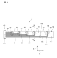
- FIG. 1 is a plan view showing a first embodiment of an elastic device
- FIG. FIG. 2 is a cross-sectional view taken along the line II-II of FIG. 1
- FIG. 4 is a plan view showing a state of preparation for attachment of an elastic device
- FIG. 4 is a sectional view along IV-IV in FIG. 3
- It is explanatory drawing which shows the use condition of an expansion-contraction device.
- Fig. 10 is a plan view showing a second embodiment of an elastic device
- 7 is a cross-sectional view taken along line VII-VII of FIG. 6
- FIG. Fig. 11 is a plan view showing a third embodiment of an elastic device
- FIG. 9 is a cross-sectional view taken along line IX-IX of FIG. 8;
- FIG. 11 is a plan view showing a fourth embodiment of an elastic device; 11 is a cross-sectional view taken along line XI-XI of FIG. 10; FIG. FIG. 11 is a plan view showing a fifth embodiment of an elastic device; 13 is a cross-sectional view taken along line XIII-XIII of FIG. 12; FIG. FIG. 11 is a plan view showing a sixth embodiment of an elastic device; FIG. 11 is a plan view showing a seventh embodiment of an elastic device;
- FIG. 1 is a plan view showing a first embodiment of an elastic device
- FIG. FIG. 2 is a cross-sectional view taken along the line II--II in FIG.
- the stretchable device is attached to a living body and used to measure biological signals.
- the side of the stretchable device that is attached to the living body is also referred to as the back side
- the side opposite to the back side is also referred to as the front side.
- the top view of the elastic device corresponds to the drawing of the front side of the elastic device.
- the stretchable device 1 includes a stretchable base material 10, a stretchable wiring 20 provided on the stretchable base material 10, and a stretchable wiring 20 provided on the stretchable base material 10. and a bio-electrode 30 electrically connected for contact with a living body.
- the stretchable base material 10 has a sheet-like body portion 11 and a plurality of sheet-like projecting piece portions 15 .
- the main body 11 is made of an elastic resin material such as thermoplastic polyurethane (TPU).
- the protruding piece 15 is made of a resin material having elasticity, such as thermoplastic polyurethane (TPU), like the main body 11 .
- the material forming the body portion 11 and the material forming the projecting portion 15 may be the same or different.
- the thickness of the body portion 11 is, for example, 20 ⁇ m to 200 ⁇ m.
- the thickness of the projecting portion 15 is, for example, 1 ⁇ m to 100 ⁇ m.
- the thickness of the body portion 11 and the thickness of the projecting portion 15 may be the same or different.
- the body portion 11 includes a first main surface 111 , a second main surface 112 facing the first main surface 111 , and a peripheral edge 113 between the first main surface 111 and the second main surface 112 .
- the first principal surface 111 is the surface on the front side of the elastic device 1
- the second principal surface 112 is the surface on the rear side of the elastic device 1, which is the side to be attached to the living body.
- the body portion 11 extends in the first direction A and is formed in a strip shape.
- the peripheral edge 113 includes a first edge 114 and a second edge 115 extending along the first direction A and positioned on both sides of a second direction B orthogonal to the first direction A. As shown in FIG.
- the body portion 11 has a first end portion 116 and a second end portion 117 positioned at both ends in the first direction A, respectively.
- the width of the body portion 11 is constant along the first direction A. As shown in FIG. The width refers to the length in the second direction B.
- the projecting piece 15 is connected to the peripheral edge 113 so as to be bendable toward the second main surface 112 side.
- the projecting piece portion 15 includes a third main surface 151 continuous with the first main surface 111 and a fourth main surface 152 continuous with the second main surface 112 and facing the third main surface 151 . That is, the third principal surface 151 is flush with the first principal surface 111 , and the fourth principal surface 152 is flush with the second principal surface 112 .
- the protruding piece 15 is formed integrally with the main body 11 .
- the plurality of protruding pieces 15 are connected to the first edge 114 and arranged side by side along the first direction A. As shown in FIG.
- the projecting piece 15 has a circular head and a neck narrower than the head, and the neck is connected to the main body 11 .
- the protruding piece 15 may be separate from the main body 11, or the protruding piece 15 may be attached to the main body 11 with an adhesive or the like.
- An adhesive layer 16 is provided on the second main surface 112 of the main body portion 11 and on the fourth main surface 152 of the projection portion 15 .
- the adhesive layer 16 is made of, for example, an acrylic material, a urethane material, or a silicone material. By having the adhesive layer 16 in this manner, when the projecting piece 15 is bent toward the second main surface 112 , the projecting piece 15 can easily maintain contact with the second main surface 112 . Also, the elastic device 1 can be attached to the living body by the adhesive layer 16 . Note that the adhesive layer 16 may be provided only on the second main surface 112 . Hereinafter, in the drawings of the second to sixth embodiments, the adhesive layer 16 is omitted.
- the bioelectrode 30 is made of a stretchable conductive material.
- a stretchable conductive material for example, a mixture of metal powder such as silver or copper and elastomeric resin such as silicone is used.
- the bioelectrode 30 is composed of an electrode layer and a gel layer, and the gel layer is preferably made of a conductive gel material containing water, a moisturizing agent, an electrolyte, and the like. As a result, even a weak signal can be easily detected because of its high adhesion to the living body.
- the bioelectrode 30 is arranged on the third main surface 151 .
- the bioelectrode 30 is formed, for example, by printing so as to be in direct contact with the third major surface 151 .
- the bioelectrode 30 may be arranged on the third main surface 151 via another member such as an insulating member.
- a plurality of bioelectrodes 30 are present, and each bioelectrode 30 is arranged on each projecting piece 15 .
- the bioelectrode 30 is formed in a circular shape.
- the diameter of the bioelectrode 30 is preferably 5 mm or more and 40 mm or less, more preferably 10 mm or more and 30 mm or less, and still more preferably 10 mm or more and 20 mm or less. Thereby, the biological signal can be efficiently measured.
- the bioelectrode 30 may have a polygonal shape such as an ellipse or a square.
- the stretchable wiring 20 is made of a stretchable conductive material.
- a stretchable conductive material for example, a mixture of metal powder such as silver or copper and elastomeric resin such as silicone is used.
- the expandable wiring 20 has a body side wiring portion arranged on the first main surface 111 and a projecting piece side wiring portion arranged on the third main surface 151 .
- the expandable wiring 20 is formed, for example, by printing so as to be in direct contact with the first main surface 111 .
- the expandable wiring 20 may be arranged on the first main surface 111 via another member such as an insulating member.
- a plurality of elastic wires 20 exist, and each elastic wire 20 is connected to each bioelectrode 30 .
- the plurality of expandable wires 20 each extend along the first direction A and are arranged side by side in the second direction B. As shown in FIG. Each expandable wire 20 extends along the first direction A from the first end 116 and further extends in the second direction B toward the corresponding bioelectrode 30 .
- the second direction B is also referred to as the width direction of the body portion 11 .
- the length of the expandable wire 20 in the first direction A increases as the position where the expandable wire 20 is arranged moves from the first end edge 114 to the second end edge 115 .
- connection terminal 40 is connected to the first end portion 116 .
- the connection terminal 40 can be connected to the second end portion 117 , and the connection terminal 40 can be attached to and detached from the second end portion 117 .
- the connection terminal 40 is electrically connected to the expandable wiring 20 .
- the connection terminal 40 has, for example, a connector and a control circuit. It is not essential for the present invention that the connection terminal 40 is detachable from the second end portion 117 .
- the plurality of projecting pieces 15 are connected to the first edge 114 , they may be connected to both the first edge 114 and the second edge 115 . Moreover, the plurality of projecting pieces 15 are connected to the first edge 114 , but the projecting piece 15 farthest from the first end 116 is connected to the second end 117 . good too. In other words, the projecting piece 15 is connected to the second end 117 located at the end of the main body 11 in the direction parallel to the first direction A. As shown in FIG. Also, the number of projecting pieces 15 is the same as the number of bioelectrodes 30, but the number of projecting pieces 15 is not particularly limited.
- a plurality of bioelectrodes 30 may be arranged on one projecting piece 15 .
- the shape of the projecting piece 15 is not limited to a circular shape, and may be, for example, a rectangular shape.
- the plurality of flexible wirings 20 includes a first group of flexible wirings connected to the first end portion 116 and extending toward the second end portion 117 , and a group of flexible wirings connected to the second end portion 117 and extending toward the first end portion 116 . and a second group of expandable wires extending toward.
- the length of the expandable wire in the first direction A becomes become longer.
- the length of the expansion and contraction wiring in the first direction A increases as the position where the expansion and contraction wiring is arranged moves from the first end edge 114 to the second end edge 115. Become.
- FIG. 3 is a plan view showing a preparation state for wearing the elastic device.
- FIG. 4 is a sectional view along IV-IV in FIG. As shown in FIGS. 3 and 4, the projecting piece 15 is bent toward the second main surface 112 from the state shown in FIGS. position and the elastic device 1 is ready to be worn.
- the projecting piece 15 contacts the adhesive layer 16 .
- the bent protrusion 15 contacts the adhesive layer 16 , thereby fixing the protrusion 15 to the second main surface 112 of the main body 11 via the adhesive layer 16 .
- the adhesive layer 16 plays a role of adhesion to the living body.
- the center of the bioelectrode 30 is arranged at the central portion in the width direction of the body portion 11 .
- the central portion in the width direction of the body portion 11 refers to the central region when the first main surface 111 of the body portion 11 is divided into three equal parts in the width direction. According to this, when the main body part 11 is attached to the living body, the bioelectrode 30 can be easily installed at a desired position of the living body.
- the second main surface 112 side of the main body 11 is attached to the living body, and the elastic wiring 20 is attached to the living body. It is located on the opposite side of the body, making it difficult to come into contact with the living body.
- the projecting piece 15 is bent toward the second main surface 112 , and the bioelectrode 30 is located on the second main surface 112 side with respect to the main body 11 . That is, the bioelectrode 30 is located on the opposite side of the stretchable wire 20 with respect to the main body 11 .
- the stretchable device 1 when the stretchable device 1 is attached to a living body and a biological signal is detected, the biological signal can be detected by bringing the biomedical electrode 30 into contact with the living body. Therefore, it is possible to reduce the noise of the biosignal generated by the contact of the elastic wire 20 with the living body, and reduce the discomfort of the subject caused by the contact of the elastic wire 20 with the skin.
- FIG. 5 is an explanatory diagram showing how the stretchable device is used.
- the stretchable device 1 in the ready-to-wear state shown in FIG. Specifically, the main body 11 is wrapped around the human body H so that the bioelectrode 30 is in contact with the human body H, and the second end 117 of the main body 11 is connected to the connection terminal 40 . In this manner, the stretchable device 1 is fixed to the human body H, and the biomedical signals of the human body H are measured by the bioelectrodes 30 .
- the elastic device 1 may be wrapped around a part of the human body H other than the chest.
- the bioelectrode 30 is in contact with the human body H, while the elastic wiring 20 is less likely to touch the human body H. Therefore, the noise of the biosignal can be reduced, the human body H does not feel uncomfortable, and pressure points are not formed. suppressed.
- the elastic device 1 can be fixed to the human body H by the connection terminal 40, it is possible to prevent displacement of the signal detection position.
- the main body part 11 extends in the first direction A, the main body part 11 can be wrapped around the human body H, and biosignals can be detected in a wider range. As a result, detection accuracy can be improved.
- Such a stretchable device 1 is used for vital measurements such as electrocardiogram (ECG), electromyography (EMG), electroencephalography (EEG) and electrical impedance tomography (EIT).
- the extensible device 1 is in a state in which the projecting piece portion 15 is not bent as shown in FIG. , the projecting piece portion 15 is bent. Therefore, the elastic device 1 is in the state shown in FIG. 1 when stored before use, and in the state shown in FIG. 3 when used.
- FIG. 6 is a plan view showing a second embodiment of an elastic device
- FIG. 7 is a cross-sectional view taken along line VII-VII of FIG.
- the second embodiment differs from the first embodiment in the configuration of the stretchable base material and the stretchable wiring. This different configuration is described below. The rest of the configuration is the same as that of the first embodiment, and the same reference numerals as those of the first embodiment are given, and the description thereof is omitted.
- the body portion 11A of the stretchable base material 10A extends in the first direction A and has a plurality of pieces arranged in the first direction A. It has a piece portion 12 and a connecting portion 13 that connects two pieces 12 adjacent to each other in the first direction A. As shown in FIG.
- the piece portion 12 includes a first principal surface 121 and a second principal surface 122 facing the first principal surface 121 .
- the connecting portion 13 includes a fifth main surface 131 and a sixth main surface 132 facing the fifth main surface 131 .
- the individual piece portion 12 and the connecting portion 13 are arranged such that the first main surface 121 and the sixth main surface 132 face each other. Two pieces 12 adjacent to each other in the first direction A are separated from each other. That is, part of the connecting portion 13 is exposed from between the two piece portions 12 adjacent to each other in the first direction A. As shown in FIG.
- the first principal surface 111 of the main body portion 11A is composed of the first principal surface 121 of the piece portion 12, and the second principal surface 112 of the body portion 11A is composed of the second principal surface 122 of the piece portion 12. . Further, the body portion 11A includes a fifth principal surface 131 and a sixth principal surface 132 .
- the projecting piece portion 15 is connected to the piece portion 12 .
- the projecting piece portion 15 is integrally formed continuously with the individual piece portion 12 .
- the projecting piece portion 15 is not provided on the connecting portion 13 . That is, the third main surface 151 is the same surface that is continuous with the first main surface 121 , and the fourth main surface 152 is the same surface that is continuous with the second main surface 122 .
- the expandable wiring 20 ⁇ /b>A includes an individual piece-side wiring portion 21 arranged on the first main surface 121 , a connection-side wiring portion 22 arranged on the sixth main surface 132 , and a protrusion arranged on the third main surface 151 . and a one-side wiring portion 23 . That is, part of the individual piece-side wiring portion 21 is arranged on the first main surface 111 and part of the connection-side wiring portion 22 is arranged on the second main surface 112 . In addition, in FIG. 6 , the expansion wiring 20 ⁇ /b>A closest to the first edge 114 does not have the connection-side wiring portion 22 .
- the piece-side wiring portion 21 and the protrusion-side wiring portion 23 are integrally and continuously connected.
- the piece-side wiring portion 21 and the connection-side wiring portion 22 are electrically connected via the conductive member 14 .
- the conductive member 14 is, for example, an anisotropic conductive film (ACF), has conductivity in the thickness direction, and has insulation in the plane direction.
- the conductive member 14 includes a thermosetting epoxy resin and conductive particles contained in the resin. Therefore, the individual piece-side wiring portion 21 is electrically connected only to the connection-side wiring portion 22 directly above the individual piece-side wiring portion 21, and is connected to other individual piece-side wiring portions 21 adjacent in the direction of the first main surface 121 and to other individual piece-side wiring portions 21 that are not directly above the individual piece-side wiring portion 21. It does not conduct to the connection side wiring portion 22 .
- the piece portion 12 and the connecting portion 13 are adhered by the conductive member 14 .
- the individual piece portion 12 and the connecting portion 13 may be adhered by another adhesive member.
- the length of the individual pieces 12 in the first direction A and the length of the connecting portion 13 in the first direction A are preferably the same. Thereby, the individual piece portion 12 and the connecting portion 13 can be formed in the same shape, and the individual piece portion 12 and the connecting portion 13 can be manufactured by the same process.
- the length of the main body 11A in the first direction A can be adjusted.
- the main body portion 11A can be manufactured separately into the piece portion 12 and the connecting portion 13, thereby improving the yield.
- the length of the connecting portion 13 can be adjusted.
- the length of the main body portion 11A in the first direction A can be adjusted.
- the length of the plurality of individual piece portions 12 can be made constant, and the manufacture of the plurality of individual piece portions 12 is facilitated.
- the numbers of the individual pieces 12 and the connecting parts 13 are not particularly limited. Also, the number of projecting piece portions 15 connected to one individual piece portion 12 is not particularly limited.
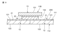
- FIG. 8 is a plan view showing a third embodiment of an elastic device; 9 is a cross-sectional view taken along line IX-IX of FIG. 8.
- FIG. 3rd Embodiment differs in the structure of an elastic base material from 2nd Embodiment. This different configuration is described below. The rest of the configuration is the same as that of the second embodiment, and the same reference numerals as those of the second embodiment are given, and the description thereof is omitted.
- the body portion 11B of the stretchable base material 10B includes a plurality of piece portions 12 arranged in the first direction A, and a connecting portion 13 that connects two adjacent piece portions 12 to each other.
- the two pieces 12 adjacent in the first direction A are separated from each other, but in the third embodiment, the two pieces 12 adjacent in the first direction A are separated from each other. in contact. That is, a part of the connecting portion 13 is not exposed from between the two piece portions 12 adjacent to each other in the first direction A.
- Two pieces 12 adjacent to each other in the first direction A are preferably in full contact along the second direction B, but may be partially separated.
- the length of the connecting portion 13 in the first direction A is preferably shorter than the length of the piece portion 12 in the first direction A. Thereby, the connecting portion 13 can be made smaller, and the manufacturing cost of the connecting portion 13 can be reduced. Since other configurations are the same as those of the second embodiment, description thereof will be omitted.
- the first principal surface 111 of the main body portion 11B is composed of the first principal surface 121 of the piece portion 12, and the second principal surface 112 of the body portion 11B is composed of the second principal surface of the piece portion 12. It consists of a surface 122 . Further, main body portion 11B includes fifth main surface 131 and sixth main surface 132 .
- connection-side wiring portion 22 of the expandable wiring 20 is less likely to be exposed on the second main surface 112 side of the main body portion 11, so that the subject's discomfort is further reduced and the noise of the biosignal is reduced. can be reduced more. Since other effects of the configuration are the same as those of the second embodiment, description thereof will be omitted.
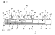
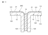
- FIG. 10 is a plan view showing a fourth embodiment of an elastic device. 11 is a cross-sectional view taken along line XI-XI of FIG. 10.
- FIG. The fourth embodiment differs from the second embodiment in the configuration of the stretchable base material and the stretchable wiring. This different configuration is described below. The rest of the configuration is the same as that of the second embodiment, and the same reference numerals as those of the second embodiment are given, and the description thereof is omitted.
- the body portion 11C of the stretchable base material 10C has a plurality of piece portions 12 arranged in the first direction A. That is, in the second embodiment, the main body portion has a connecting portion, but in the fourth embodiment, it does not have a connecting portion.
- the expandable wiring 20C has the individual piece-side wiring portion 21 arranged on the first main surface 121 and the protruding piece-side wiring portion 23 arranged on the third main surface 151 . That is, in the second embodiment, the expandable wiring has the connection-side wiring portion, but in the fourth embodiment, it does not have the connection-side wiring portion.
- the end 123 of one piece 12 on the side of the other piece 12 and the end portion 123 of the piece 12 on the other side is such that the first main surface 121 of the end portion 123 of one of the individual piece portions 12 and the first main surface 121 of the end portion 123 of the other individual piece portion 12 face each other. , is folded and connected.
- the end portion 123 of one individual piece portion 12 and the end portion 123 of the other individual piece portion 12 are bonded by the conductive member 14 .
- the first principal surface 111 of the main body portion 11C is composed of the first principal surface 121 of the piece portion 12, and the second principal surface 112 of the body portion 11C is composed of the second principal surface 122 of the piece portion 12. .
- the individual piece-side wiring portion 21 arranged on one piece portion 12 and the individual piece-side wiring portion 21 arranged on the other piece portion 12 are connected to the end portion 123 of one piece portion 12 and the other piece portion.
- the ends 123 of the 12 face each other and are electrically connected via the conductive member 14 .
- the length of the main body portion 11C in the first direction A can be adjusted by adjusting the number of the piece portions 12 .
- the main body portion 11C can be manufactured by dividing it into individual piece portions 12, which improves the yield.
- the elastic wiring 20C is less likely to be exposed on the second main surface 112 side with respect to the main body portion 11C, the subject's discomfort can be further reduced, and the noise of the biosignal can be further reduced. Since other effects of the configuration are the same as those of the second embodiment, description thereof will be omitted.
- FIG. 12 is a plan view showing a fifth embodiment of an elastic device; 13 is a cross-sectional view taken along line XIII--XIII of FIG. 12.
- FIG. The fifth embodiment differs from the third embodiment in the position of the bioelectrode and the configuration of the stretchable base material. This different configuration is described below. The rest of the configuration is the same as that of the third embodiment, and the same reference numerals as those of the third embodiment are given, and the description thereof is omitted.
- the bioelectrode 30 is arranged on the fourth main surface 152 of the projecting piece 15.
- the protrusion 15 is arranged with respect to the main body 11D such that the third principal surface 151 is along the first principal surface 111 and the fourth principal surface 152 is along the second principal surface 112 . That is, the projecting piece 15 is not bent toward the first main surface 111 side and the second main surface 112 side.
- the protruding piece 15 is arranged such that the third main surface 151 is parallel to the first main surface 111 and the fourth main surface 152 is parallel to the second main surface 112, so that the main body portion 11D is formed. placed against.
- "parallel” means not only being completely parallel, but also being substantially parallel to the extent that the projecting piece 15 is not bent toward the first main surface 111 side and the second main surface 112 side. include.
- the projecting piece portion 15 is connected to the connecting portion 13.
- the projecting piece portion 15 is formed integrally and continuously with the connecting portion 13 .
- the projecting piece portion 15 is not provided on the individual piece portion 12 . That is, the third main surface 151 is the same surface that is continuous with the fifth main surface 131 , and the fourth main surface 152 is the same surface that is continuous with the sixth main surface 132 .
- the protrusion-side wiring portion 23 is arranged on the fourth main surface 152 , and the bioelectrode 30 is connected to the protrusion-side wiring portion 23 .
- the protrusion-side wiring portion 23 is connected to the connection-side wiring portion 22 , and the connection-side wiring portion 22 is electrically connected to the individual piece-side wiring portion 21 via the conductive member 14 .
- the bioelectrode 30 is electrically connected to the individual-side wiring portion 21 .
- the bioelectrode 30 is arranged on the fourth main surface 152, the projecting piece 15 has the third main surface 151 parallel to the first main surface 111, and the fourth main surface 152 is parallel to the first main surface 111. It is arranged with respect to the main body portion 11 ⁇ /b>D so as to be parallel to the second main surface 112 . Therefore, even if the projecting portion 15 is not bent, the bioelectrode 30 is present on the opposite side of the elastic wire 20A with respect to the main body portion 11D, so that the subject's discomfort can be reduced and the noise of the biosignal can be reduced. In addition, since there is no need to bend, the inspection can be performed quickly. In addition, even when the elastic device 1D is repeatedly used for inspection, deterioration due to bending of the projecting piece portion 15 is unlikely to occur. Since other effects of the configuration are the same as those of the third embodiment, description thereof will be omitted.
- FIG. 14 is a plan view showing a sixth embodiment of an elastic device.
- the sixth embodiment differs from the first embodiment in the configuration of the expandable wiring. This different configuration is described below. The rest of the configuration is the same as that of the first embodiment, and the same reference numerals as those of the first embodiment are given, and the description thereof is omitted.
- the stretchable wires 20E1 to 20E5 extend from the first end 116 along the first direction A, and the bioelectrodes 30 extend from the stretchable wires 20E1 to 20E5. It is electrically connected to the wirings 20E1 to 20E5.
- first flexible wiring 20E1, the second flexible wiring 20E2, the third flexible wiring 20E3, the fourth flexible wiring 20E4, and the fifth flexible wiring 20E5 extend from the first edge 114 toward the second edge 115. are arranged in parallel.
- the fifth distance L5 becomes longer in order, and the width of the first stretchable wiring 20E1, the width of the second stretchable wiring 20E2, the width of the third stretchable wiring 20E3, the width of the fourth stretchable wiring 20E4, and the width of the fifth stretchable wiring 20E5 are , and so on.
- the biological signal is weak and easily attenuated while being transmitted from the detection position to the detector.
- the width of the flexible wiring 20E1 to 20E5 according to the transmission distance (including distances L1 to L5), signal attenuation is less likely to occur even in long-distance transmission, enabling highly accurate signal detection regardless of the signal transmission distance. can.
- each expandable wire When each expandable wire extends along the first direction from either one of the first end and the second end, each expandable wire extends from either end to the bioelectrode.
- the width of the expandable wire increases as the shortest distance in the first direction to the connected portion increases.
- the plurality of expandable wires are connected to the first end and extend toward the second end, and a group of expandable wires are connected to the second end and extend toward the first end.
- a second group of expandable wires may be provided.
- the expansion and contraction wires of the first group are compared with each other, and in each expansion and contraction wire, the longer the shortest distance in the first direction from the first end to the portion connected to the bioelectrode, the wider the expansion and contraction wire.
- the second group of expandable wires, in each expandable wire the longer the shortest distance in the first direction from the second end to the portion connected to the bioelectrode, the wider the expandable wire.
- the main body of the stretchable base material has a strip shape, but is not limited to this shape, and may have, for example, a non-long shape such as a polygon, a circle, or an oval. , is connected to the periphery of the main body, the stretchable wiring is provided on the main body, and the bioelectrode is provided on the projecting piece.
- the main body portion of the stretchable base material is strip-shaped and extends linearly, but it may extend curvedly, meandering, or spirally.
- the main body of the stretchable base material is strip-shaped, and the width of the main body is constant along the first direction, but may vary along the first direction. It may have a bead shape in which a plurality of circular portions are connected, or may have a shape in which circular portions and belt-like portions are alternately connected.
- the plurality of projecting pieces are connected to the first edge in the above embodiment, they may be connected to at least one of the first edge and the second edge. Although there are a plurality of protrusions, a single protrusion may be provided.
- the projecting piece is connected to the peripheral edge of the main body, but may be connected to one of the first main surface and the second main surface of the main body, or may be connected to the first main surface together with the peripheral edge. It may be connected to one of the surface and the second main surface.
- the expandable wires are arranged on the first main surface and the third main surface. It may be arranged on the surface. Also, at least part of the expansion/contraction wiring may be arranged on the first main surface and the other part thereof may be arranged on the second main surface.
- the expandable wiring has a projecting piece-side wiring portion.
- the projecting piece side wiring portion may be omitted.
- FIG. 15 is a plan view showing a seventh embodiment of an elastic device;
- the seventh embodiment is different from the first embodiment in the configuration of the expansion/contraction wiring, further including a connecting portion. This different configuration is described below.
- the rest of the configuration is the same as that of the first embodiment, and the same reference numerals as those of the first embodiment are given, and the description thereof is omitted.
- the stretchable base material 10F further has connecting portions 17 .
- the connection portion 17 is connected to a second edge 115 positioned at the end portion in the second direction B of the main body portion 11 .
- the ends of the flexible wirings 20F1 to 20F4 are arranged in the connecting portion 17.
- the connecting portion 17 is located at the center of the second edge 115 in the first direction A. As shown in FIG.
- connection terminal 40 is attached to the connection portion 17 and connected to the ends of the expansion/contraction wirings 20F1 to 20F4. According to this, for example, an external device (not shown) can be connected to the connection terminal 40 to transmit signal data to the external device. Various data can be measured or detected by an external device.
- the multiple stretchable wires 20F1 to 20F4 extend from the connection terminal 40 to the multiple bioelectrodes 30F1 to 30F4, respectively.
- the width of ⁇ 20F4 becomes wider.
- the first bioelectrode 30F1, the second bioelectrode 30F2, the third bioelectrode 30F3, and the fourth bioelectrode 30F4 are arranged in parallel in order from the first end 116 toward the second end 117. be done. That is, the second bioelectrode 30F2 and the third bioelectrode 30F3 are arranged closer to the connecting part 17 than the first bioelectrode 30F1 and the fourth bioelectrode 30F4.
- the first elastic wire 20F1 is connected to the first bioelectrode 30F1.
- the second elastic wire 20F2 is connected to the second bioelectrode 30F2.
- the third stretchable wire 20F3 is connected to the third bioelectrode 30F3.
- the fourth stretchable wire 20F4 is connected to the fourth bioelectrode 30F4.
- the first distance L1 of the first flexible wiring 20F1 and the fourth distance L4 of the fourth flexible wiring 20F4 are greater than the second distance L2 of the second flexible wiring 20F2 and the third distance L3 of the third flexible wiring 20F3. too long.
- the first distance L1 and the fourth distance L4 are the same, and the second distance L2 and the third distance L3 are the same.
- the width of the first elastic wire 20F1 and the width of the fourth elastic wire 20F4 are wider than the width of the second elastic wire 20F2 and the width of the third elastic wire 20F3.
- the width of the first flexible wiring 20F1 and the width of the fourth flexible wiring 20F4 are the same, and the width of the second flexible wiring 20F2 and the width of the third flexible wiring 20F3 are the same.
- the biological signal is weak and easily attenuated while being transmitted from the detection position to the detector.
- the width of the flexible wiring 20F1 to 20F4 according to the transmission distance (including distances L1 to L4), signal attenuation is less likely to occur even in long-distance transmission, enabling highly accurate signal detection regardless of the signal transmission distance.
- the first distance L1 to the fourth distance L4 may be different from each other, and the longer the first distance L1 to the fourth distance L4, the wider the width of the expandable wirings 20F1 to 20F4 corresponding to each distance. Become.
- the elastic device 1F may be attached to the human body as it is, or the first end 116 and the second end 117 may be brought into contact with each other to form the elastic device 1F into a belt shape so as to be in close contact with the human body.
- the position of the connection terminal 40 can be adjusted.
- the stretchable device 1F can measure various parts of the human body.
- the elastic device 1F can be adjusted to an optimum shape according to the measurement location.
- connection terminals 40 are not arranged on the first end portion 116 and the second end portion 117 . That is, since it is possible to omit the elastic wiring from the first end 116 and the second end 117, the first end 116 and the second end 117 can be connected in various ways. Specifically, the first end 116 and the second end 117 may be connected such that they overlap, or the first end 116 and the second end 117 may be integrated. . In this way, various connection methods are made possible, and the elastic device 1F can be changed into an optimum structure according to the measurement location.
- the shape of the connecting portion 17 is not particularly limited, and may be rectangular as shown in FIG. 15 or may be circular. Also, the position of the connection portion 17 in the first direction A is not particularly limited, but is preferably the central portion in the first direction A. This makes it possible to arrange the expandable wires and the bioelectrodes symmetrically with respect to the central portion, which facilitates the printing of the expandable wires and the bioelectrodes. Also, the connecting portion 17 may be connected to the first edge 114 .
- the elastic device 1F may include a plurality of connection terminals 40, each of which may be arranged at one of the first end portion 116, the second end portion 117, and the connection portion 40. By connecting to the connecting terminal 40 closest to each bioelectrode 30, the length of the elastic wiring 20 can be suppressed even when the elastic device 1F is sufficiently long in the first direction.
Landscapes
- Life Sciences & Earth Sciences (AREA)
- Health & Medical Sciences (AREA)
- Medical Informatics (AREA)
- Biophysics (AREA)
- Pathology (AREA)
- Engineering & Computer Science (AREA)
- Biomedical Technology (AREA)
- Heart & Thoracic Surgery (AREA)
- Physics & Mathematics (AREA)
- Molecular Biology (AREA)
- Surgery (AREA)
- Animal Behavior & Ethology (AREA)
- General Health & Medical Sciences (AREA)
- Public Health (AREA)
- Veterinary Medicine (AREA)
- Measurement And Recording Of Electrical Phenomena And Electrical Characteristics Of The Living Body (AREA)
Priority Applications (2)
| Application Number | Priority Date | Filing Date | Title |
|---|---|---|---|
| JP2023559488A JP7544290B2 (ja) | 2021-11-11 | 2022-10-11 | 伸縮デバイス |
| US18/434,958 US20240172983A1 (en) | 2021-11-11 | 2024-02-07 | Stretchable device |
Applications Claiming Priority (2)
| Application Number | Priority Date | Filing Date | Title |
|---|---|---|---|
| JP2021184266 | 2021-11-11 | ||
| JP2021-184266 | 2021-11-11 |
Related Child Applications (1)
| Application Number | Title | Priority Date | Filing Date |
|---|---|---|---|
| US18/434,958 Continuation US20240172983A1 (en) | 2021-11-11 | 2024-02-07 | Stretchable device |
Publications (1)
| Publication Number | Publication Date |
|---|---|
| WO2023084971A1 true WO2023084971A1 (ja) | 2023-05-19 |
Family
ID=86335665
Family Applications (1)
| Application Number | Title | Priority Date | Filing Date |
|---|---|---|---|
| PCT/JP2022/037797 Ceased WO2023084971A1 (ja) | 2021-11-11 | 2022-10-11 | 伸縮デバイス |
Country Status (3)
| Country | Link |
|---|---|
| US (1) | US20240172983A1 (https=) |
| JP (1) | JP7544290B2 (https=) |
| WO (1) | WO2023084971A1 (https=) |
Citations (4)
| Publication number | Priority date | Publication date | Assignee | Title |
|---|---|---|---|---|
| JP2004033468A (ja) * | 2002-07-03 | 2004-02-05 | Fukuda Denshi Co Ltd | 生体電極 |
| WO2009041496A1 (ja) * | 2007-09-25 | 2009-04-02 | Dainippon Sumitomo Pharma Co., Ltd. | 電極シート及び電極シートの製造方法 |
| JP2018042686A (ja) * | 2016-09-13 | 2018-03-22 | 国立大学法人大阪大学 | 電極シート |
| JP2020151104A (ja) * | 2019-03-19 | 2020-09-24 | 日東電工株式会社 | 貼付型生体センサ |
Family Cites Families (7)
| Publication number | Priority date | Publication date | Assignee | Title |
|---|---|---|---|---|
| IL165232A0 (en) * | 2004-11-16 | 2005-12-18 | Tapuz Medical Technologies T M | An ergometry belt |
| EP2158454B1 (en) * | 2007-05-18 | 2018-08-22 | University of Southern California | Biomimetic tactile sensor for control of grip |
| AU2014274726B2 (en) * | 2013-06-06 | 2018-07-19 | Tricord Holdings, L.L.C. | Modular physiologic monitoring systems, kits, and methods |
| JP6974990B2 (ja) * | 2017-09-06 | 2021-12-01 | 日本メクトロン株式会社 | 濡れセンサ及び濡れ検知システム |
| EP3682941B1 (en) * | 2019-01-18 | 2021-11-10 | Ecole Polytechnique Federale De Lausanne (EPFL) EPFL-TTO | Biomedical device comprising a mechanically adaptive member |
| CA3133235A1 (en) * | 2019-03-11 | 2020-09-17 | Benjamin I. Rapoport | Intradural neural electrodes |
| JP7283654B2 (ja) * | 2019-03-12 | 2023-05-30 | 日本メクトロン株式会社 | 粘着シート |
-
2022
- 2022-10-11 WO PCT/JP2022/037797 patent/WO2023084971A1/ja not_active Ceased
- 2022-10-11 JP JP2023559488A patent/JP7544290B2/ja active Active
-
2024
- 2024-02-07 US US18/434,958 patent/US20240172983A1/en active Pending
Patent Citations (4)
| Publication number | Priority date | Publication date | Assignee | Title |
|---|---|---|---|---|
| JP2004033468A (ja) * | 2002-07-03 | 2004-02-05 | Fukuda Denshi Co Ltd | 生体電極 |
| WO2009041496A1 (ja) * | 2007-09-25 | 2009-04-02 | Dainippon Sumitomo Pharma Co., Ltd. | 電極シート及び電極シートの製造方法 |
| JP2018042686A (ja) * | 2016-09-13 | 2018-03-22 | 国立大学法人大阪大学 | 電極シート |
| JP2020151104A (ja) * | 2019-03-19 | 2020-09-24 | 日東電工株式会社 | 貼付型生体センサ |
Also Published As
| Publication number | Publication date |
|---|---|
| JP7544290B2 (ja) | 2024-09-03 |
| JPWO2023084971A1 (https=) | 2023-05-19 |
| US20240172983A1 (en) | 2024-05-30 |
Similar Documents
| Publication | Publication Date | Title |
|---|---|---|
| US9901273B2 (en) | Bioelectrode | |
| US11493889B2 (en) | Wearable device | |
| US20160128597A1 (en) | Thin planar biological sensor | |
| US10980465B2 (en) | Sensor assembly | |
| CN111419218A (zh) | 一种可穿戴电子设备 | |
| JP7305449B2 (ja) | 医療センサ | |
| US12383181B2 (en) | Elastic wearable sensor | |
| WO2023084971A1 (ja) | 伸縮デバイス | |
| US11547363B2 (en) | Physiological sensor device and system, and correction method | |
| US10881305B2 (en) | Wearable thoracic element for detecting, monitoring and reporting the physiological status of an individual | |
| CN215227731U (zh) | 一种易穿戴的心电导联线及心电图机 | |
| US12251225B2 (en) | Non-invasive diagnostic assembly and method of using same | |
| CN212694262U (zh) | 可穿戴设备 | |
| US20230113963A1 (en) | Neuromuscular transmission monitoring system and kinemyography sensor | |
| CN219835620U (zh) | 心电贴片 | |
| EP4061474B1 (en) | Electrode for recording electroencephalographic signals and/or stimulating patients | |
| KR20240043002A (ko) | 반지 내경 조절 장치 및 이를 포함하는 반지 형태의 생체 신호 감지 장치 | |
| CN219630441U (zh) | 电极绑带以及电极绑带组件 | |
| WO2025204598A1 (ja) | ウェアラブルデバイス | |
| HK40057773A (en) | Elastic wearable sensor | |
| WO2021248308A1 (zh) | 一种可穿戴电子设备 | |
| WO2026083549A1 (ja) | ウェアラブルデバイス | |
| HK40057773B (zh) | 弹性可穿戴传感器 | |
| CN117982145A (zh) | 心电传感组件及心电传感装置 | |
| JP2022080763A (ja) | 電極構造 |
Legal Events
| Date | Code | Title | Description |
|---|---|---|---|
| 121 | Ep: the epo has been informed by wipo that ep was designated in this application |
Ref document number: 22892471 Country of ref document: EP Kind code of ref document: A1 |
|
| WWE | Wipo information: entry into national phase |
Ref document number: 2023559488 Country of ref document: JP |
|
| 122 | Ep: pct application non-entry in european phase |
Ref document number: 22892471 Country of ref document: EP Kind code of ref document: A1 |